

Page 1
9/11
Page 2
2
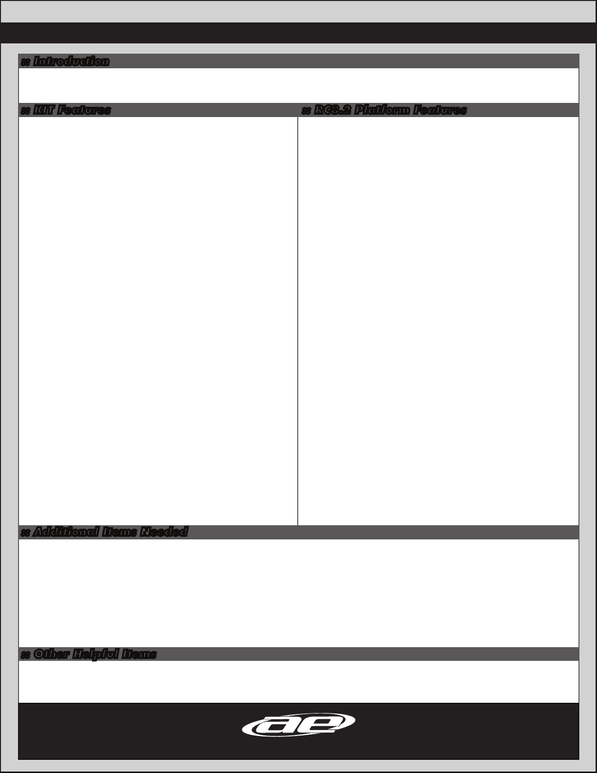
:: Introduction
Thank you for purchasing this Team Associated product. This manual contains instructions and tips for building and maintaining your new
RC8.2e Factory Team, 1/8 scale racing buggy. Please take a moment to read through it an familiarize yourself with these steps as they will help
you to understand each component’s function and show you some tips for getting the most out of your RC8.2e Factory Team build experience.
:: KIT Features :: RC8.2 Platform Features
• New Factory Team blue aluminum sliding motor mount allows for quick and
easy removal of motor and center diff
• Factory Team 3mm lengthened 7075 hard anodized chassis
• Newly designed suspension arms feature centerline shock mounts and
optimized anti-roll bar position
• 4.30:1 ratio gearboxes
• 43T diff ring and 10T pinion for increased punch and durability over
conventional buggy ratio gearboxes
• Caster blocks adjust 14, 16, or 18 degrees with molded inserts
• 3.5mm light CVA drivetrain with protective boots on center and rear joints
• Factory Team 16mm ‘Big Bore’ hard anodized threaded shocks with 4mm
titanium nitride coated shafts
• Factory Team 5mm 7075 aluminum low-CG shock towers with optimized
geometry
• Factory Team 7075 blue aluminum pivot plates
• Factory Team 7075 blue aluminum steering knuckles
• Factory Team 7075 aluminum axles and gearbox input cups
• Factory Team 7075 blue aluminum chassis top plate and lightweight steering
posts
• Factory Team lightweight diff outdrives and ring gears
• JConcepts Punisher Body and Factory Team 83mm wheels
• JConcepts Illuzion wing with NEW Factory Team low-CG wing mount
• 3.5mm light CVA drivetrain with protective boots on center and rear drives
• Factory Team shock and differential fluids included
• Rubber sealed bearings
• Front and rear hubs use large 15mm x 24mm rubber sealed bearings
(used on the inside)
• 14 other 8mm x 16mm bearings throughout the car
• Steel alloy turnbuckles
• Molded suspension pivot bushings for adjustable pivot height
• Blue Aluminum hexes and nylon locking wheel nuts
• Large speed control mounting area raised off of chassis to allow for easy
screw mounting of common speed controllers.
• Speed control mounting area includes convenient switch-mounting boss.
• Utilizes 3 hook-and-loop straps to secure LiPo batteries into battery tray.
• Molded battery tray supports 7.4-14.8V battery packs with room for foam
pads.
• Accepts 2S, 3S, 4S, LiPo battery packs:
#628 Reedy LiPo 5500 mAh 7.4V 60C (2),
#685 Reedy LiPo 5000 mAh 7.4V 40C w/connector (2),
#709 Reedy LiPo 5000 mAh 7.4V 35C w/connector (2).
• Sealed receiver box for electronics placement.
• Receiver, servo, and battery tray remove from vehicle in one piece for easy
maintenance and cleaning.
• Convenient wire routing keeps critical electronic wires out of drivetrain
components and simplifies disassembly.
:: Additional Items Needed
Your RC8.2e FT kits comes with the latest components used by our factory race team to win races.
However the following components are necessary to complete the build:
• 2 channel radio/transmitter set with switch – FM/PCM/2.4GHz recommended
• Transmitter batteries (#302, 303 recommended)
• 1/8 Scale Specific Speed Control, Motor, and pinion (see motor manufacturer’s gearing recommendations for correct pinion size).
• Plug Extension (depending on ESC)
• High Torque Steering Servo (AE Part # 29167)
• 1/8th scale buggy tires • CA (Cyanoacrylic) glue (#1597 recommended)
• Polycarbonate specific spray paint or polycarbonate specific bottled paint and airbrush
• Needle nose pliers • Hobby knife • Reamer/hole punch • Ride Height Gauge (#1449 recommended)
:: Other Helpful Items
• Silicone Shock Fluid / Differential Fluid (Refer to catalog for complete listings)
• Body Scissors (AE Part # 1737) • Wire cutters • Soldering Iron • FT Threadlock (#1596)
• FT Hex Wrenches (AE Part # 1541, 1655) • Multi Tool (AE Part #7494) • FT Turnbuckle Wrench (#89240)
• FT Nut Drivers (AE Part #1561, 1663-1668) • Calipers or a Precision Ruler • Green Slime shock lube (AE Part # 1105)
Associated Electrics, Inc.
26021 Commercentre Dr.
Lake Forest, CA 92630
http://www.TeamAssociated.com · http://www.RC10.com · http://twitter.com/Team_Associated · http://bit.ly/AEonFacebook
Customer Service
Tel: 949.544.7500
Fax: 949.544.7501
Page 3
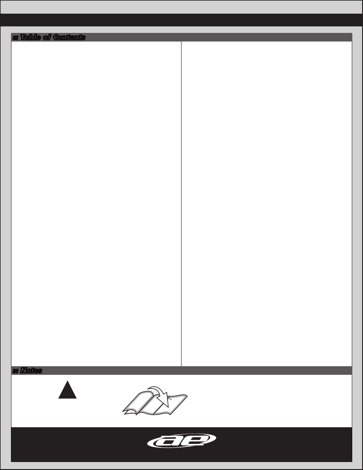
:: Table of Contents
1....................Cover
2....................Introduction
3....................Table of Contents
BAG A & AA
4....................Chassis Assembly
3
Bag L
32................Wheels, Tires, and Body Install
32................Building Tips
33................Chassis Tips
33................Front End Tips
BAG B
4-5...............Steering Assembly
Bag C & CC
6-9...............Front, Rear, and Center
Differential Assembly
Bag D & DD
9-11.............Front Bulkhead Assembly
Bag E & EE
11-14..........Front Suspension Assembly
Bag F & FF
15-16..........Rear Bulkhead Assembly
Bag G & GG
16-19..........Rear Suspension Assembly
Bag H
20-21..........Wing Assembly
34................Rear End Tips
35................Droop Settings
36-45.........Catalog
45................Contact Info
46................Notes
47.................Setup Sheet “Kit Setup”
48................1:1 Hardware “Fold Out
49................Setup Sheet “Blank”
50................Back Cover
Bag I & II
21-23.........Center Bulkhead Assembly
Bag J & JJ
24-26.........Shock Assembly
Bag K
27-31..........Radio Tray Assembly
:: Notes
There is a 1:1 hardware foldout page in the back
of the manual. To check the size of a part, line
!
This symbols indicates a
special note or instruction
in the manual.
Associated Electrics, Inc.
26021 Commercentre Dr.
Lake Forest, CA 92630
http://www.TeamAssociated.com · http://www.RC10.com · http://twitter.com/Team_Associated · http://bit.ly/AEonFacebook
up your hardare with the correct drawing until
you find the exact size. Each part in the foldout
has a number assigned to it for ordering
replacement parts.
Customer Service
Tel: 949.544.7500
Fax: 949.544.7501
Page 4
4
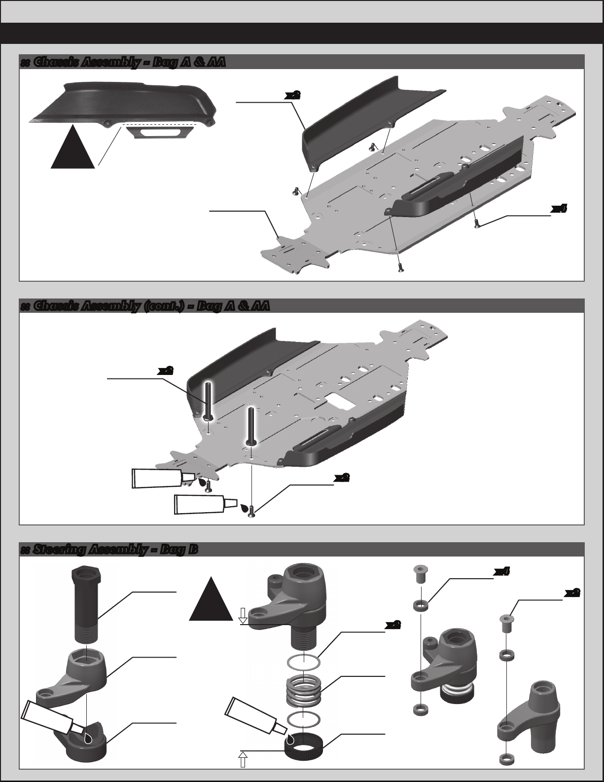
:: Chassis Assembly - Bag A & AA
89552
RC8.2
side
guards
!
Note: cut fuel
tubing brace off of
the left side guard.
89476
FT RC8B
+3mm
chassis
:: Chassis Assembly (cont.) - Bag A & AA
89485
RC8B
aluminum
steering
posts
x2
x2
25201
3x8mm
fhcs
x4
#1596
thread lock
#1596
thread lock
:: Steering Assembly - Bag B
89016
Servo
saver
#6588
black grease
bolt
89015
Servo
saver
arm
89015
Servo
saver
bellcrank
gap setting:
!
7mm
#1596
thread lock
89214
4x12mm
fhcs
x2
89117
Diff
shim
89016
Servo
saver
spring
89016
Servo
saver
retainer
x2
89161
5x8mm
bearing
x4
89014
Steering
rack post
x2
Page 5
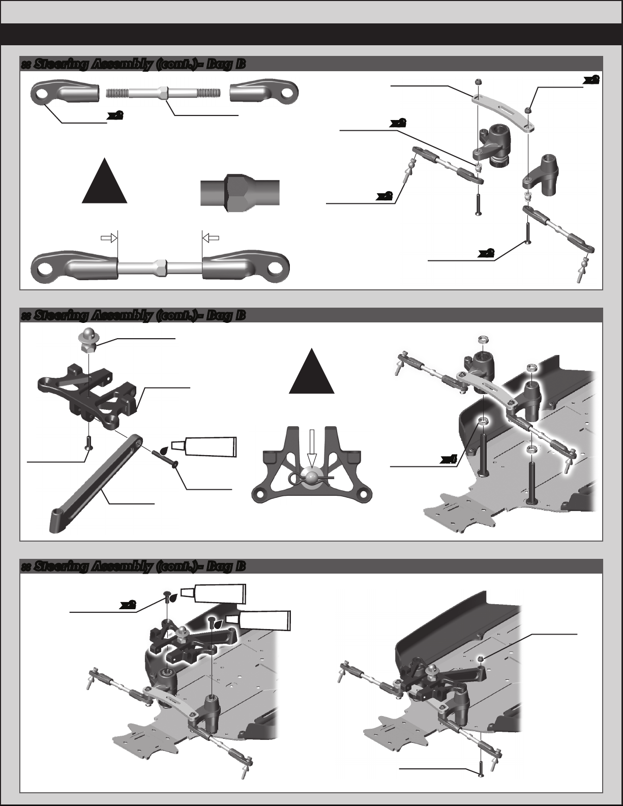
:: Steering Assembly (cont.)- Bag B
89074
Steering
eyelet
x2
89526
50mm steel
turnbuckle
Smooth edge towards
drivers side!
89077
Flanged
pivot ball
89242
Steering
drag link
x2
25215
M3
locknut
5
x2
!
Build Two
29mm
:: Steering Assembly (cont.)- Bag B
89011
Front body
mount
89234
Aluminum
top plate
(blue)
#1596
25202
3x10mm
fhcs
89258
Front chassis
brace
(plastic)
thread lock
89455
3x22mm
fhcs
89075
RC8
steering
ballstuds
!
note the direction
of the body post
during installation.
x2
31404
6x10mm
bearing
89455
3x22mm
fhcs
x4
x2
:: Steering Assembly (cont.)- Bag B
#1596
89214
4x12mm
fhcs
x2
thread lock
#1596
thread lock
25215
M3
locknut
89209
3x18mm
fhcs
Page 6
6
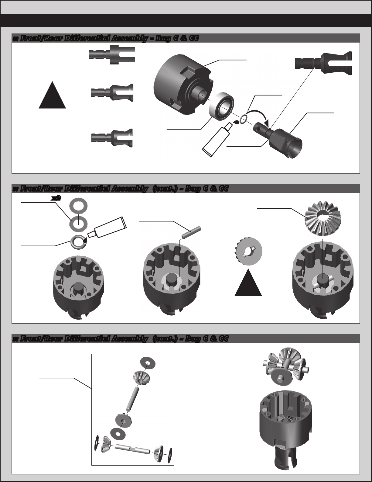
:: Front/Rear Differential Assembly - Bag C & CC
89115
Center Diff
Outdrive
!
Diff outdrive
differences
Front Diff
Outdrive
(long)
25236
8x16mm
bearing
Rear Diff
Outdrive
(short)
:: Front/Rear Differential Assembly (cont.) - Bag C & CC
89120
Diff
washer
89121
Diff
O-Ring
x2
#6588
black grease
89120
Diff
outdrive
pin
housing
#6588
black grease
(front, long)
Diff
89477
Light
outdrives
89121
Diff
O-Ring
89120
Sun gear
89478
Light
outdrives
(rear, short)
groove in sun gear
:: Front/Rear Differential Assembly (cont.) - Bag C & CC
89120
Spider
gear
assembly
!
Align pin with
Page 7
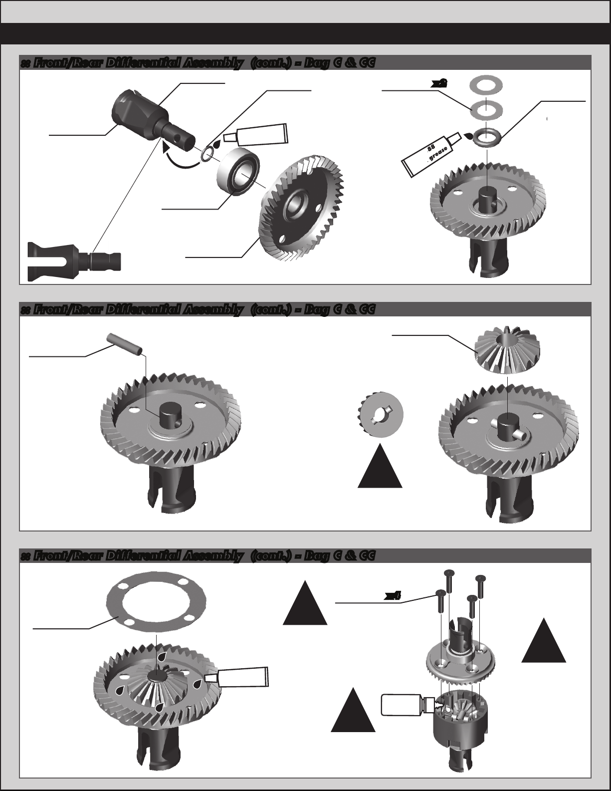
:: Front/Rear Differential Assembly (cont.) - Bag C & CC
O-Ring
89477
Light
outdrives
(front, long)
89478
Light
outdrives
(rear, short)
black grease
25236
8x16mm
bearing
89494
Light diff
ring gear
89121
Diff
O-Ring
#6588
:: Front/Rear Differential Assembly (cont.) - Bag C & CC
89120
Diff
washer
#6588
black grease
7
x2
89121
Diff
O-Ring
89120
Diff
outdrive
pin
Align pin with
groove in sun gear
:: Front/Rear Differential Assembly (cont.) - Bag C & CC
89208
3x14mm
fhcs
89116
Diff
gasket
!
Tighten screws
evenly and firmly.
#6588
black grease
!
Fill with diff fluid to
top of gears.
!
x4
Diff fluid
5,000cst
#5453
89120
Sun gear
!
Build
front and
rear diffs!
Page 8
8
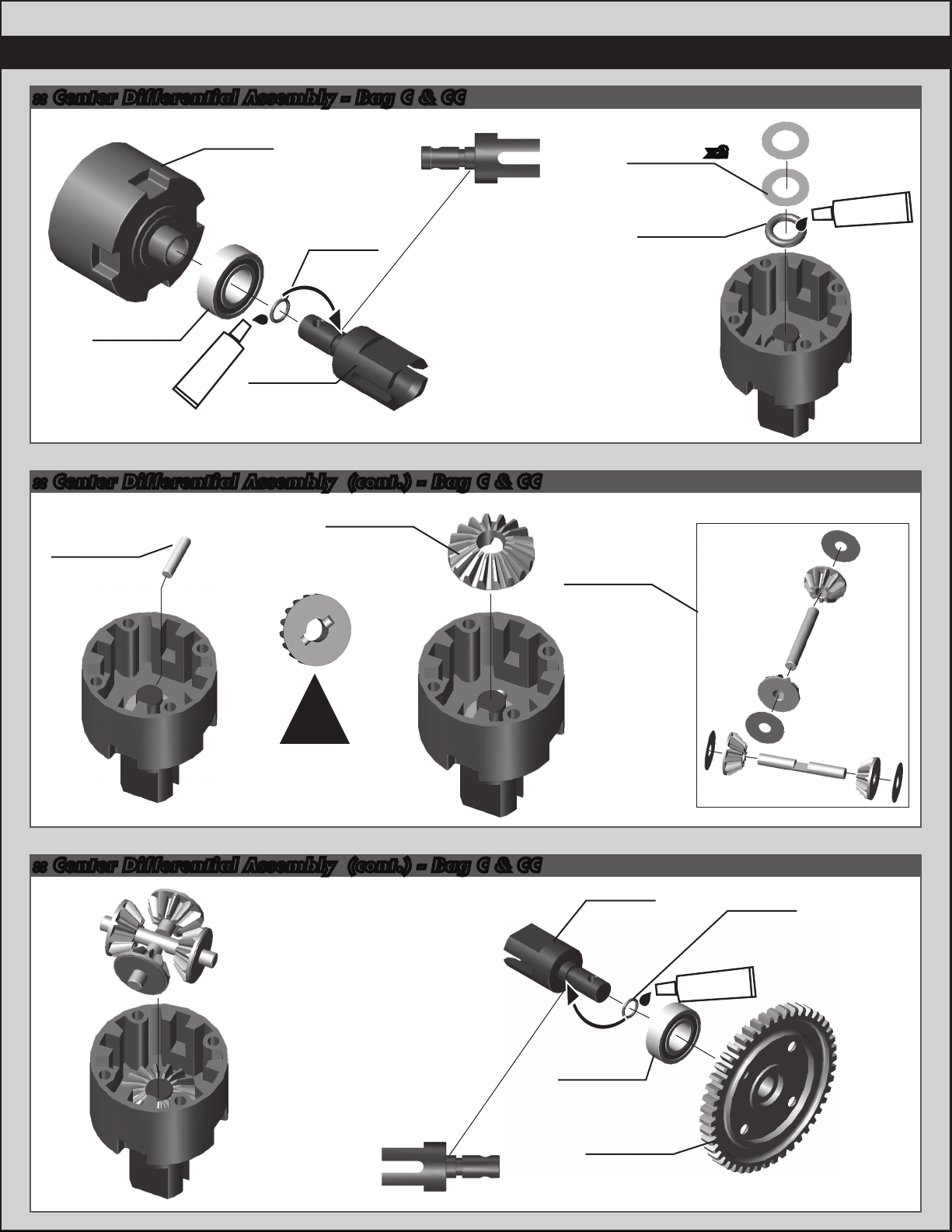
:: Center Differential Assembly - Bag C & CC
89115
Diff
housing
89121
Diff
O-Ring
25236
8x16mm
bearing
#6588
black grease
89119
Diff
outdrives
(center)
:: Center Differential Assembly (cont.) - Bag C & CC
89120
89120
Diff
outdrive
pin
Sun gear
89120
Spider
gear
assembly
89120
Diff
washer
89121
Diff
O-Ring
x2
#6588
black grease
!
Align pin with
groove in sun gear
:: Center Differential Assembly (cont.) - Bag C & CC
89119
Diff
outdrives
(center)
25236
8x16mm
bearing
89519
Plastic
spur gear
(46T)
89121
Diff
O-Ring
#6588
black grease
Page 9
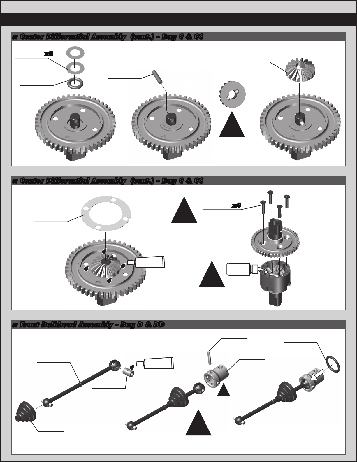
:: Center Differential Assembly (cont.) - Bag C & CC
9
Diff
x2
89120
Diff
outdrive
pin
89120
Diff
washer
89121
O-Ring
:: Center Differential Assembly (cont.) - Bag C & CC
89116
Diff
gasket
Tighten screws
evenly and firmly.
!
89120
Sun gear
!
Align pin with
groove in sun gear
89208
3x14mm
fhcs
x4
#6588
black grease
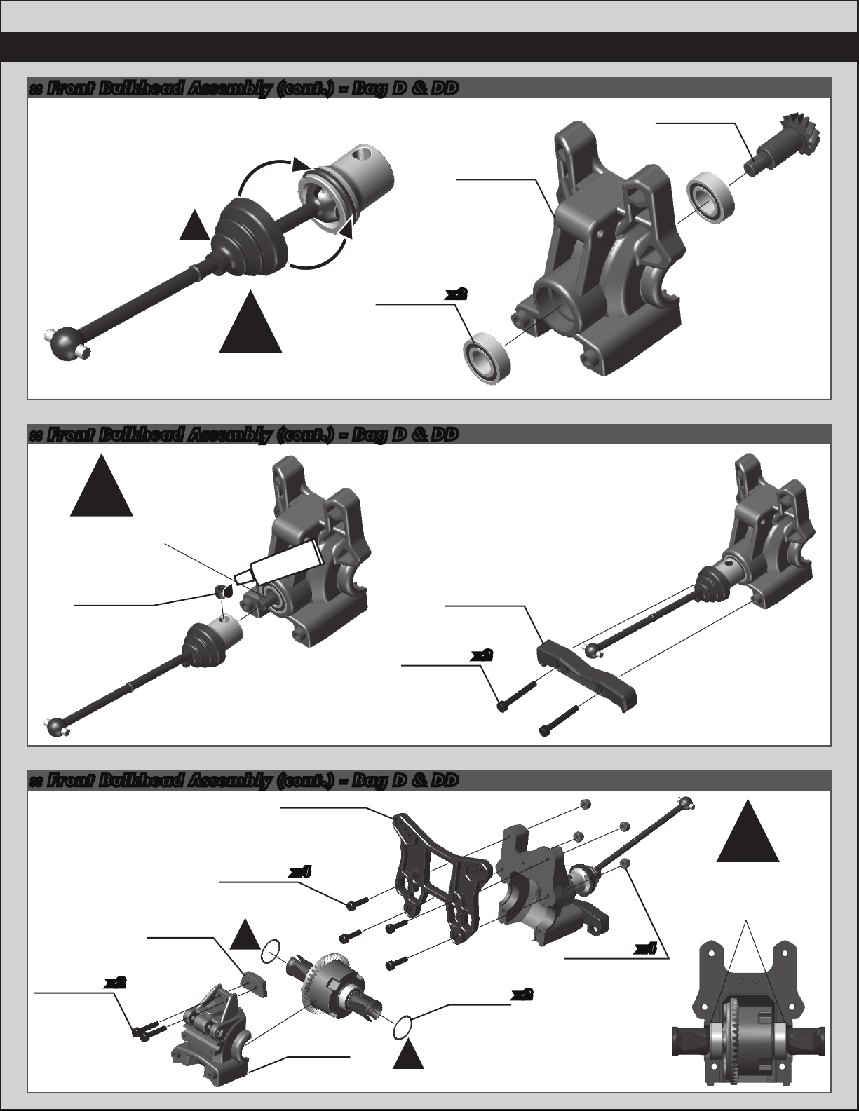
:: Front Bulkhead Assembly - Bag D & DD
89103
Center CVA
bone
(front)
89106
CVA
u-joint
coupler
#6588
black grease
Diff fluid
5,000cst
#5453
!
Fill with diff fluid to
top of gears.
89106
CVA pin
!
89286
Gearbox
input cup
(aluminum)
89557
Pin
retainer
O-ring
89557
Pin
retainer
boot
!
Input cup has additional holes
for crosspin to extend the life of
the input cup.
Page 10
10
:: Front Bulkhead Assembly (cont.) - Bag D & DD
!
89114
Diff pinion
gear
89017
Inner
gearbox
25236
8x16mm
bearing
!
Wrap boot over the O-Ring.
:: Front Bulkhead Assembly (cont.) - Bag D & DD
!
Key setscrew onto
flat side of shaft.
Tighten with no
endplay.
89221
5x4mm
setscrew
#1596
thread lock
89474
3x22mm
shcs
x2
89481
Low
B-Plate
x2
:: Front Bulkhead Assembly (cont.) - Bag D & DD
89538
RC8.2 front
shock tower
(aluminum)
x4
89017
Outer
gearbox
!
89224
3x16mm
shcs
x2
89472
Front
bulkhead
spacer
89454
3x12mm
shcs
!
89117
Diff
shim
x2
25215
M3
locknut
!
Diff shims
installed to diff,
diff installed to
gearbox.
x4
Page 11
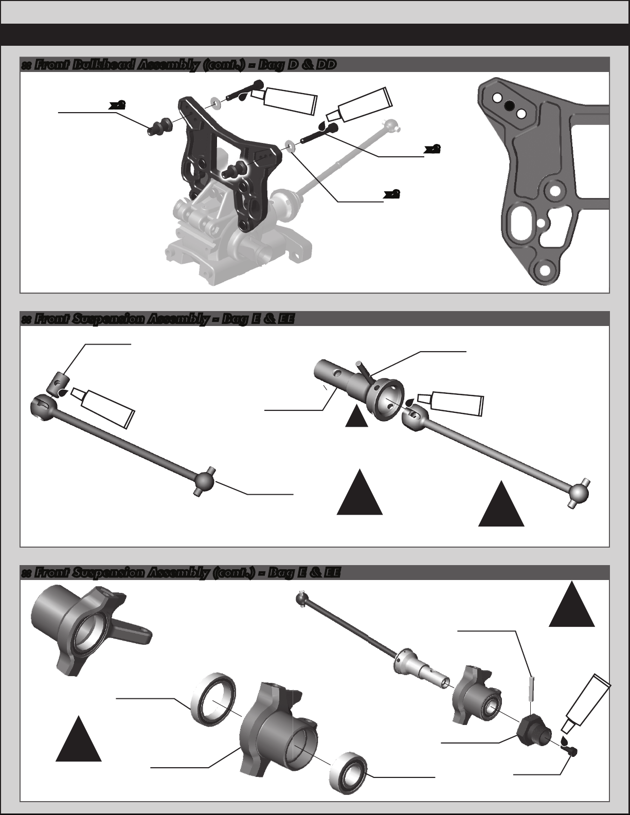
:: Front Bulkhead Assembly (cont.) - Bag D & DD
11
#1596
89473
Steel
shock
standoffs
x2
thread lock
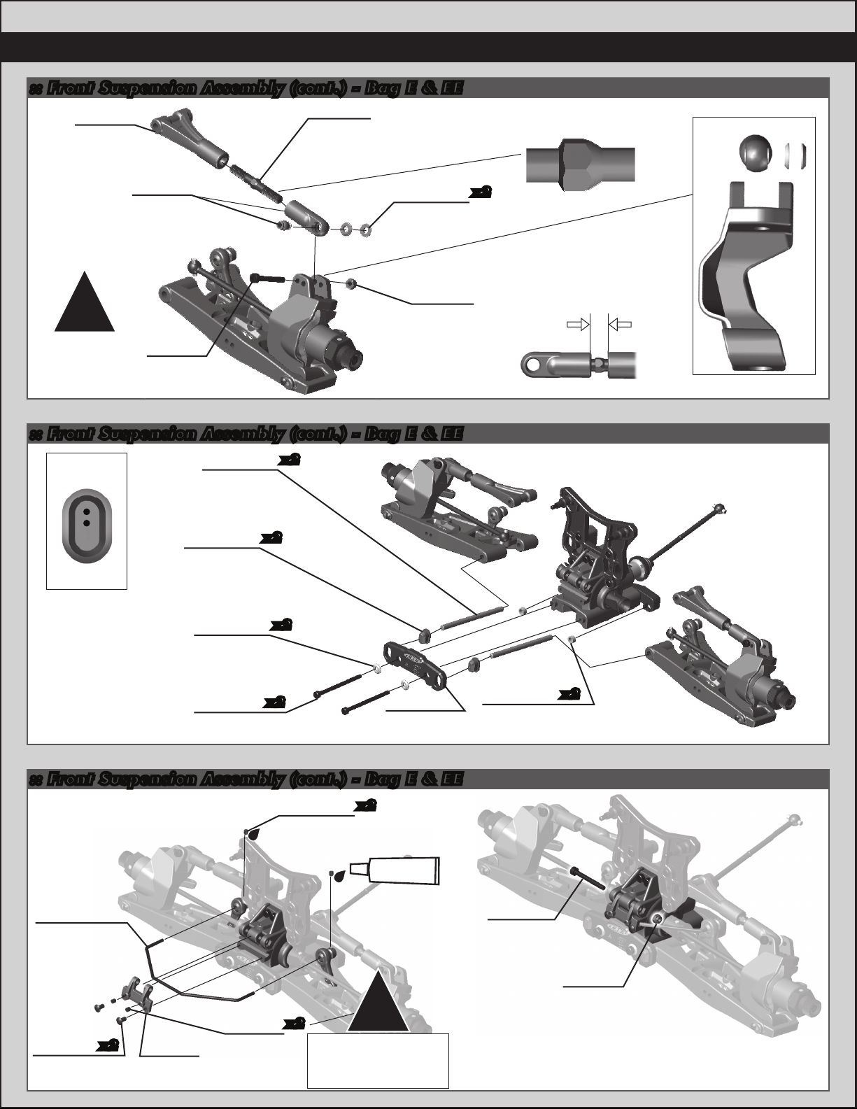
:: Front Suspension Assembly - Bag E & EE
89105
CVA
u-joint
coupler
#1596
thread lock
89230
Silver
cone
washer
89225
3x24mm
shcs
x2
x2
89105
CVA pin
3
2
1
#6588
black grease
89285
Front stub
axle
(aluminum)
89102
CVA
bone
Axle has additional holes
for crosspin to extend
the life of the Axle.
:: Front Suspension Assembly (cont.) - Bag E & EE
Right Side
89162
15x21x4mm
bearing
Left Side
!
!
#6588
black grease
Build Two!
89096
Wheel hex
pins
!
!
Build right
and left
sides!
#1596
thread lock
!
Build right
and left sides!
89380
FT machined
steering blocks
25236
8x16x5mm
bearing
89095
Wheel hex
(aluminum)
89223
3x8mm
shcs
Page 12
12
:: Front Suspension Assembly (cont.) - Bag E & EE
89029
Steering
block
bushing
#1596
thread lock
(short)
!
89206
4x10mm
bhcs
89558
RC8.2
caster
blocks
89029
Steering block
bushing (long)
89207
4x12mm
bhcs
Note:
One drop only.
Spread evenly
inside the threads.
!
Build right
and left
sides!
:: Front Suspension Assembly (cont.) - Bag E & EE
89536
RC8.2
swaybar
pivot ball
89537
RC8.2
swaybar
ball joint
89537
RC8.2
swaybar
drop link
!
Droop
screw
placement!
!
Build Two!
!
89317
Droop
screw
Note:
#1596
thread lock
#1596
thread lock
!
Do not tighten until
bushing is keyed
into steering block.
25192
3x20mm
shcs
Key bushings into
steering block.
!
!
Build right
and left
sides!
89550
RC8.2
!
front
arms
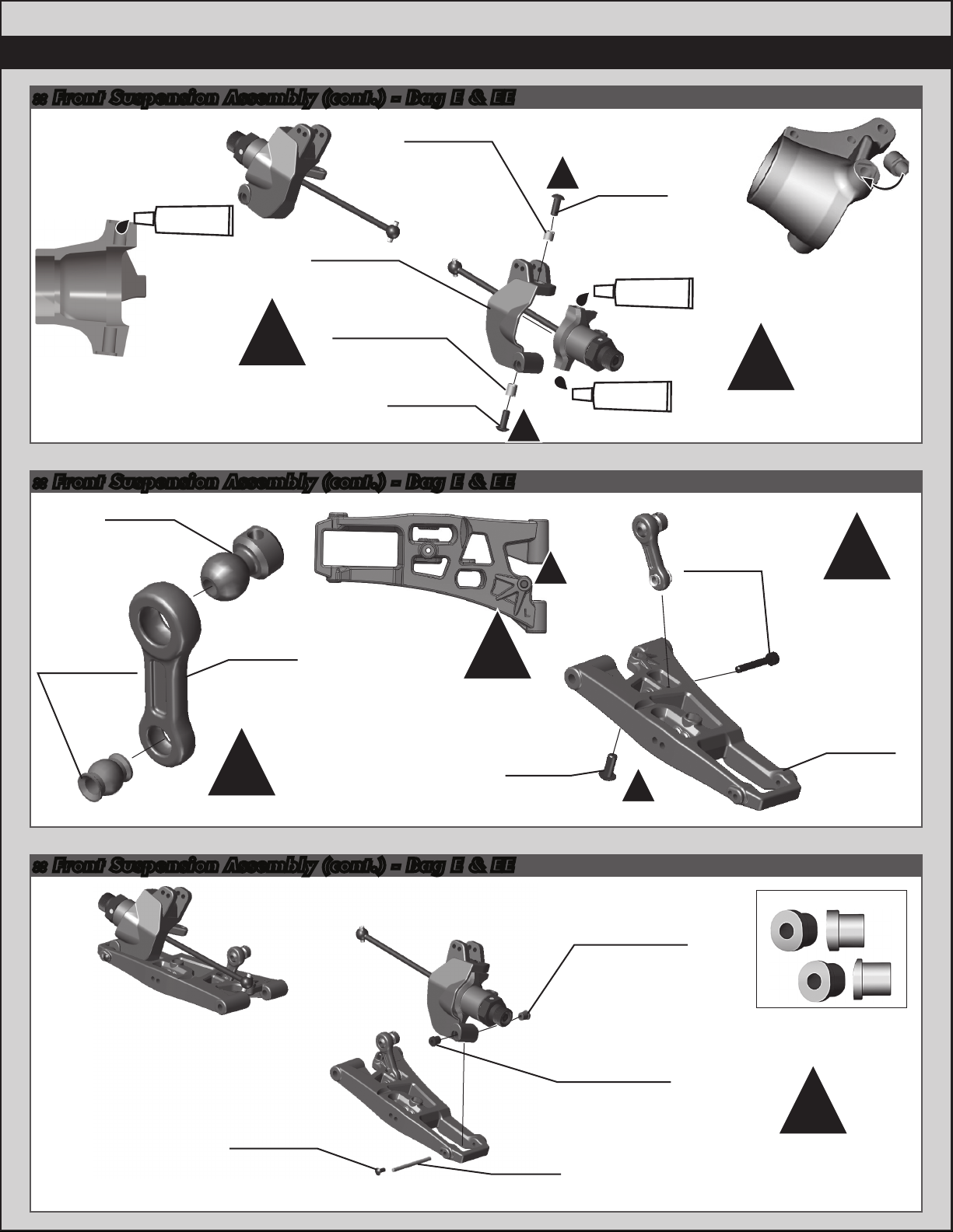
:: Front Suspension Assembly (cont.) - Bag E & EE
31520
2.5x6mm
bhcs
hinge pin
89041
Outer
89032
16 deg. caster
angle bushing
(red)
89032
16 deg. caster
angle bushing
(blue)
Note: direction
16 deg
16 deg
red
!
Build right
and left
sides!
blue
Page 13
:: Front Suspension Assembly (cont.) - Bag E & EE
89549
RC8.2
front upper
arm
89076
Camber
rod ends
89269
38mm
steel
turnbuckle
89230
Silver cone
washer
Smooth edge towards
drivers side!
x2
13
Side view
25215
!
Build right
and left
sides!
89225
3x24mm
shcs
M3
locknut
:: Front Suspension Assembly (cont.) - Bag E & EE
x2
x2
x2
x2
89460
Aluminum
A-plate
hinge pin
bushing
2 dot up
89553
RC8.2 inner
hinge pins
TiN (front)
89039
Hinge pin
bushings
(two dot)
89230
Silver cone
washer
89279
3x45mm
shcs
89482
Low B-plate
insert
x2
8mm
:: Front Suspension Assembly (cont.) - Bag E & EE
x2
#1596
thread lock
!
Tighten screws to
ensure some
movement.
89533
RC8.2 FR
swaybar
2.3 (white)
31531
3x6mm
bhcs
x2
89017
Swaybar
mount
89219
3x5mm
setscrew
25225
3x3mm
setscrew
x2
remove free play but
89227
3x28mm
shcs
25215
M3
locknut
Page 14

14
:: Front Suspension Assembly (cont.) - Bag E & EE
89227
3x28mm
shcs
89018
Gearbox
gasket
black grease
#6588
89022
Front
bumper
89217
4x14mm
89214
4x12mm
:: Front Suspension Assembly (cont.) - Bag E & EE
Shock tower
hinge pin
bushing
1 dot
89040
Upper
inner
hinge pin
x2
89039
Hinge pin
bushing
(three dot)
x2
hinge pin
bushing
3 dot down
x2
fhcs
x2
fhcs
!
Build right
and left
sides!
31531
3x6mm
bhcs
x2
89218
3x8mm
washer
89470
Shock tower
hinge pin
bushings
x2
(one dot)
x2
25215
M3
locknut
89218
3x8mm
washer
Page 15
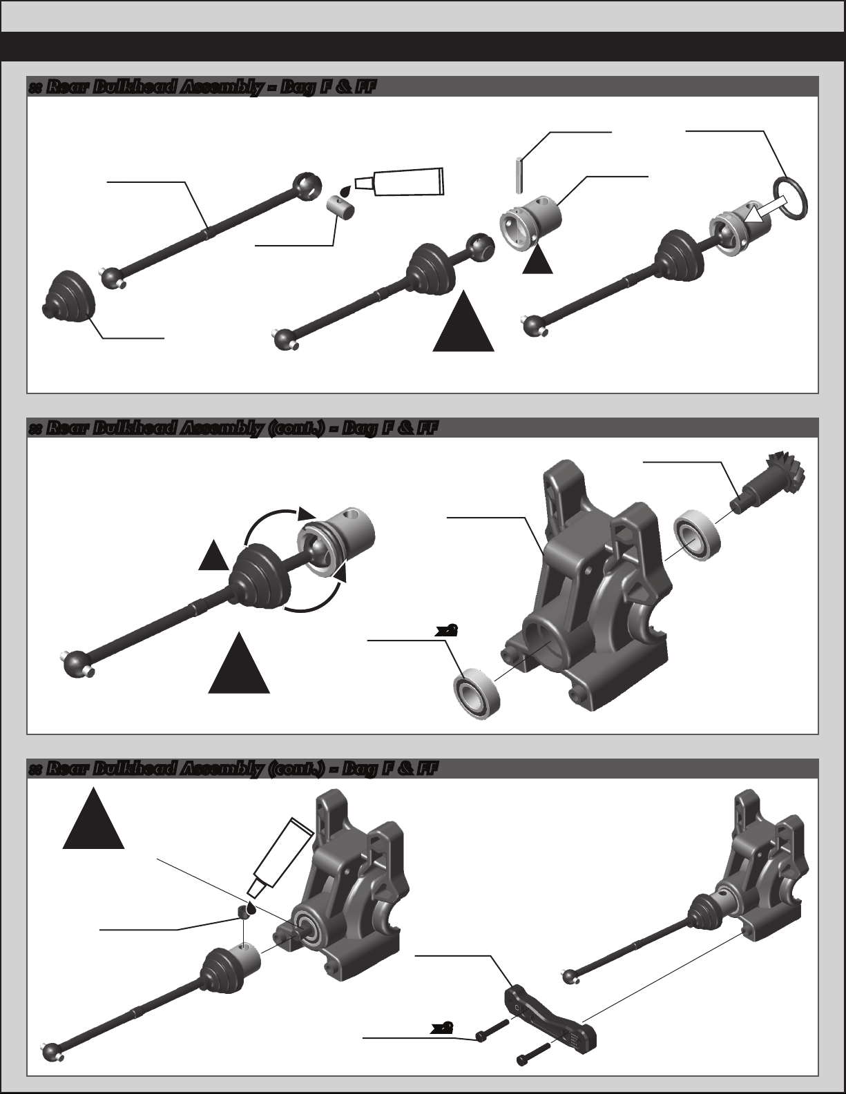
:: Rear Bulkhead Assembly - Bag F & FF
15
89560
Center CVA
bone +3mm
(rear)
89106
CVA
u-joint
coupler
89557
Pin
retainer
boot
#6588
black grease
Input cup has additional holes
for crosspin to extend the life of
the input cup.
:: Rear Bulkhead Assembly (cont.) - Bag F & FF
!
!
89017
Inner
gearbox
CVA pin
!
89106
89286
Gearbox
input cup
(aluminum)
89557
Pin
retainer
O-ring
89114
Diff pinion
gear
25236
8x16mm
bearing
!
Wrap boot over the O-Ring.
:: Rear Bulkhead Assembly (cont.) - Bag F & FF
!
Key setscrew onto
flat side of shaft.
Tighten with no
endplay.
89221
5x4mm
setscrew
#1596
thread lock
Aluminum
C-plate
25191
3x18mm
shcs
x2
89462
x2
Page 16

16
:: Rear Bulkhead Assembly (cont.) - Bag F & FF
89011
Body
mount
(rear)
x2
x2
!
89017
Outer
gearbox
89539
RC8.2 rear
shock tower
(aluminum)
3x10mm
89454
3x12mm
shcs
89224
3x16mm
shcs
25620
shcs
x2
:: Rear Bulkhead Assembly (cont.) - Bag F & FF
89225
3x24mm
shcs
x2
!
tapered side of
cone washer
faces towards
chassis brace
89227
3x28mm
shcs
!
89230
Silver
cone
washer
89117
Diff
shim
x3
25215
M3
locknut
x2
89473
Steel
shock
standoffs
x2
x2
!
Diff shims in-
stalled to diff,
diff installed to
gearbox.
3
2
1
89258
Chassis
brace
(rear)
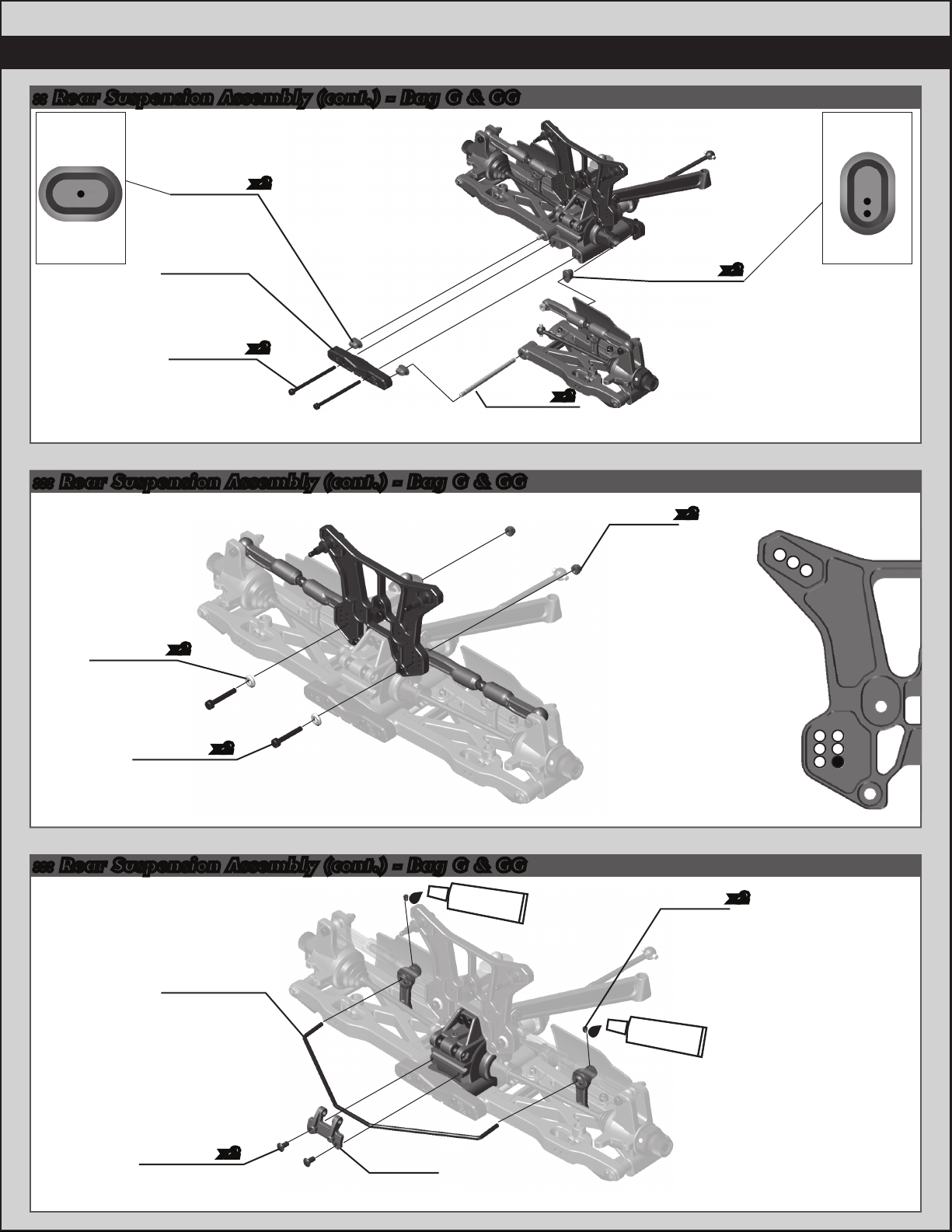
:: Rear Suspension Assembly - Bag G & GG
89105
89102
CVA
bone
u-joint
coupler
CVA
89107
CVA boot
locknut
#6588
black grease
25215
M3
36
25
14
Page 17
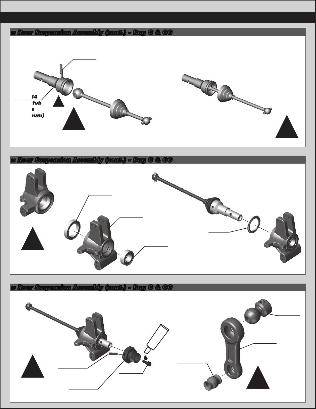
:: Rear Suspension Assembly (cont.) - Bag G & GG
89105
CVA pin
(fr/rr)
89284
Rear stub
axle
(aluminum)
!
!
Axle has additional holes
for crosspin to extend
the life of the Axle.
:: Rear Suspension Assembly (cont.) - Bag G & GG
17
!
Build Two!
89162
15x21mm
bearing
89033
hub
carrier
!
Build right
25236
8x16mm
bearing
and left
sides!
:: Rear Suspension Assembly (cont.) - Bag G & GG
#1596
thread lock
89096
!
Build right
and left
sides!
Wheel hex
pins
89095
Wheel hex
(aluminum)
89223
3x8mm
shcs
89537
RC8.2
swaybar
ball joint
89107
Bearing
shield
89536
RC8.2
swaybar
pivot ball
89537
RC8.2
swaybar
drop link
!
Build Two!
Page 18
18
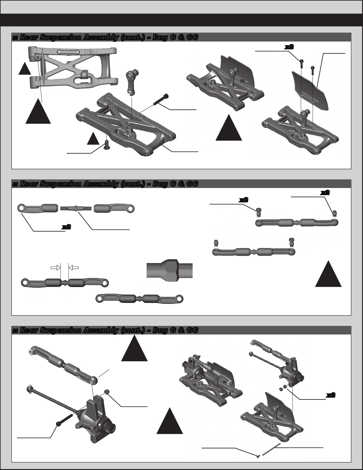
:: Rear Suspension Assembly (cont.) - Bag G & GG
!
25192
3x20mm
!
Droop
screw
placement!
89317
Droop
screw
:: Rear Suspension Assembly (cont.) - Bag G & GG
!
shcs
89551
RC8.2
rear arm
!
Build right
and left
sides!
89076
Camber
ball joints
x2
89454
3x12mm
shcs
x2
89076
Camber
pivot balls
89561
Rear
mud
guard
x2
89076
Camber
rod end
x2
6mm
89269
38mm steel
turnbuckle
Smooth edge towards
drivers side!
Passenger
Side
:: Rear Suspension Assembly (cont.) - Bag G & GG
!
Note the direction
of rod end when
installing.
Right side shown.
25215
M3
locknut
Driver
Side
!
Build right
and left
sides!
89031
Hub
spacers
x2
89474
3x22mm
shcs
!
Build right
and left
sides!
31520
2.5x6mm
bhcs
89041
Outer
hinge pin
Page 19
:: Rear Suspension Assembly (cont.) - Bag G & GG
hinge pin
bushing
19
hinge pin
bushing
89039
x2
Hinge pin
bushings
1 dot
89463
Aluminum
D-plate
89452
x2
3x50mm
shcs
89466
Inner hinge pin
(4mm HMA)
::: Rear Suspension Assembly (cont.) - Bag G & GG
x2
Hinge pin
bushings
(two dot)
25215
M3
locknut
89470
x2
x2
2 dot down
3
2
1
89230
x2
Silver cone
washer
25192
x2
3x20mm
shcs
::: Rear Suspension Assembly (cont.) - Bag G & GG
#1596
thread lock
89487
RC8B rear
swaybar
(2.5 green)
25225
3x3mm
setscrew
#1596
thread lock
36
25
14
x2
31531
3x6mm
bhcs
x2
89017
Swaybar
mount
Page 20

20
:: Wing Assembly - Bag H
89229
Blue
countersunk
washer
x2
25204
3x16mm
fhcs
25215
M3
locknut
mounts
x2
x2
89540
RC8.2
wing
x2
89540
RC8.2
Wing mount
upper brace
89304
JC Illuzion
wing
(black)
25192
3x20mm
shcs
x2
25215
M3
locknut
x2
:: Wing Assembly (cont.) - Bag H
25215
M3
!
Tighten screws to
remove free play but
ensure some
movement.
locknut
89219
3x5mm
setscrew
89228
3x40mm
shcs
x2
Page 21

:: Rear Clip Install - Bag H
21
25215
M3
locknut
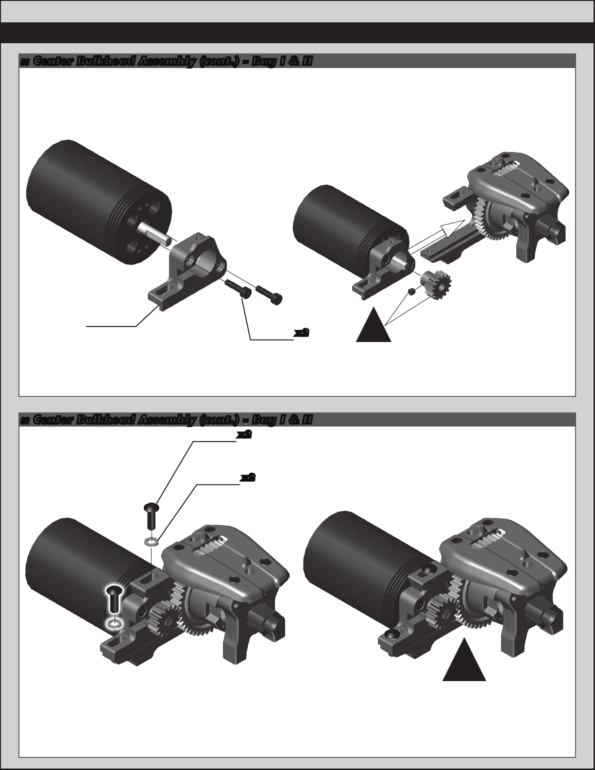
:: Center Bulkhead Assembly - Bag I & II
89019
Center
bulkhead
(top)
x2
89209
3x18mm
fhcs
#1596
threadlock
#6588
black grease
89214
4x12mm
fhcs
89217
4x14mm
fhcs
x2
89018
Gearbox
gasket
x2
3x26mm
89226
shcs
x4
89529
Motor
mount
bulkhead
89254
Center
diff top
plate
89019
Center
bulkhead
(bottom)
Page 22
22
:: Center Bulkhead Assembly (cont.) - Bag I & II
89529
Motor
mount
slide
89454
3x12mm
shcs
x2
:: Center Bulkhead Assembly (cont.) - Bag I & II
89207
4x12mm
bhcs
89503
Motor
mount
washer
x2
x2
!
Note: pinion and set screw
not included.
See motor manufatcurer’s
gearing recommendations.
!
Check your gear mesh!
See page 33 for details
Page 23
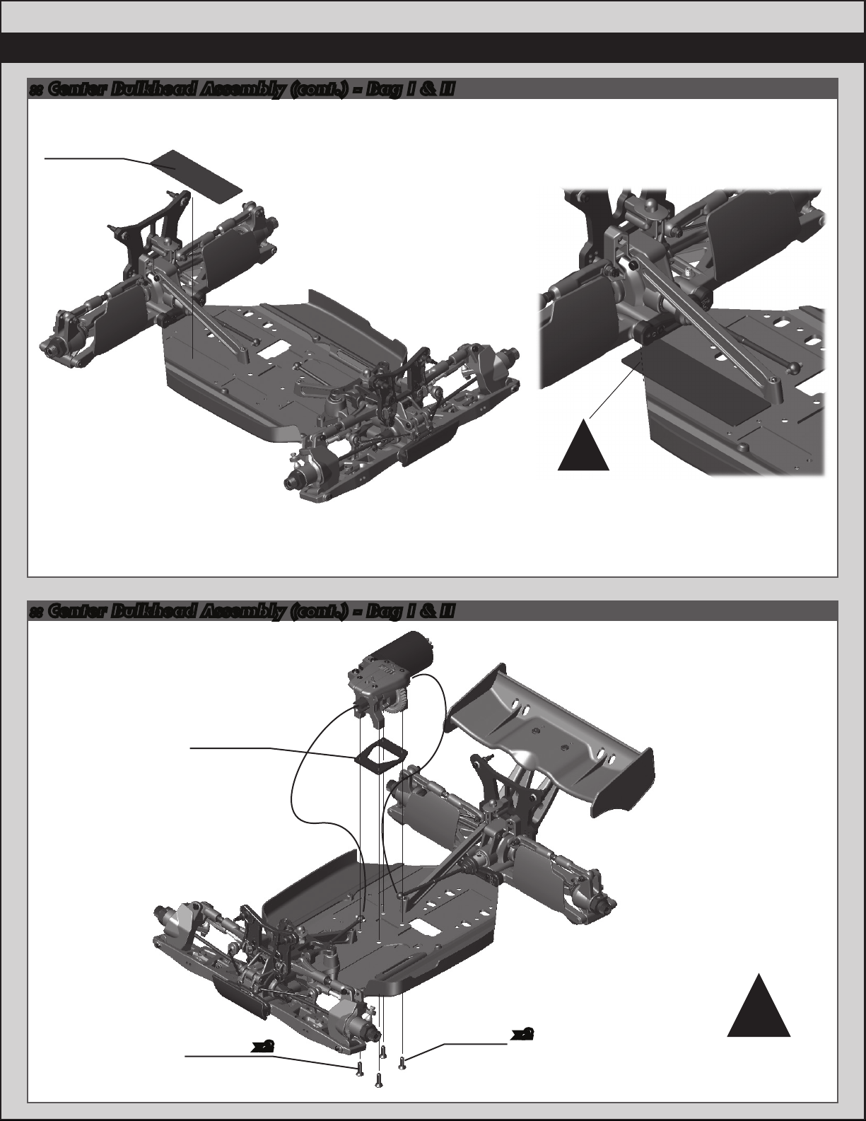
:: Center Bulkhead Assembly (cont.) - Bag I & II
89510
Motor pad
23
!
Note: trim motor
pad to fit chassis.
:: Center Bulkhead Assembly (cont.) - Bag I & II
89502
RC8e
center diff
riser
89217
4x14mm
fhcs
x2
89214
4x12mm
fhcs
x2
!
Install CVA bones
into center diff
outdrives!
Page 24

24
:: Shocks Assembly - Bag J & JJ
89066
Shock
O-rings
89352
Spacer
89358
Lower
shock tool
!
Use the lower shock tool
to load the two o-rings
and spacer for easy
lubing and installation
into the shock body
:: Shocks Assembly (cont.) - Bag J & JJ
!
Install piston tapered
side down.
89554
4x26mm
89352
O-Ring
89352
Bottom
nut
HD shock
shaft, front
89555
4x36mm
HD shock
shaft, rear
x2
89215
Locknut
(piston)
89492
16mm piston
5x1.1 + 5x1.2
89278
2.5mm
piston
washer
x2
89358
Upper
shock
tool
89291
16x29mm
FT shock body
(front)
89344
16x38mm
FT shock body
(rear)
Shock
fluid
!
Shock
fluid
!
One drop of shock
fluid on threads.
:: Shocks Assembly (cont.) - Bag J & JJ
!
Short boots for
front shocks.
Long boots for
rear shocks.
89556
RC8.2
shock boots
(fr/rr)
Shock
Fill to top with
shock fluid:
Front: 30wt
Rear 30 wt
89352
Shock boot
washer
89469
Shock rod
end ball
fluid
RACERS TIP:
Try 35 wt or 40wt
shock fluid in the
front shocks for
less agressive
steering.
89469
HD shock
ends
Page 25
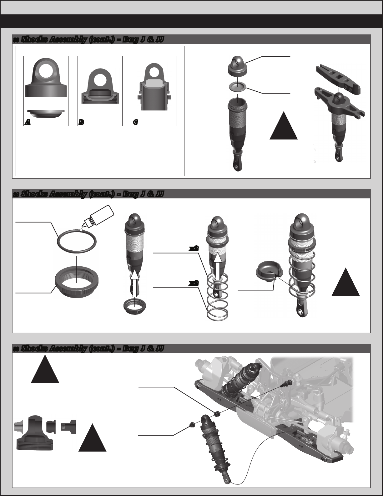
:: Shocks Assembly (cont.) - Bag J & JJ
25
Bladder Installation
A B C
As you install the shock cap with the bladder, it will force
out any extra fluid. If you install the cap with the shaft
fully extended, you are running FULL REBOUND.
To run less rebound, unthread the cap 1-2 turns and
compress the shaft to the desired position and
re-tighten the cap with the shaf t compressed.
Start with no rebound.
:: Shocks Assembly (cont.) - Bag J & JJ
89352
Threaded
shock
collar
O-Ring
Shock
fluid
89543
Front spring,
silver (4.3lbs)
(short spring)
89335
Shock
cap
89351
Shock
bladder
!
Some residual shock
fluid may appear from
your first few runs
around the shock cap
as a result of bleeding.
x2
89355
Threaded
shock
collar
Rear spring,
silver (3.55lbs)
(long spring)
:: Shocks Assembly (cont.) - Bag J & JJ
!
Note the direction
of the shock cap
when installing onto
shock standoffs
!
89083
Shock
bushing
25612
M3 locknut
with flange
Install
two front
shocks.
89547
x2
89354
16mm
shock
spring cup
!
Build two
front and
two rear
shocks!
Page 26

26
:: Shocks Assembly (cont.) - Bag J & JJ
106mm
89454
3x12mm
shcs
!
Install
two front
shocks.
:: Shocks Assembly (cont.) - Bag J & JJ
91069
Shock mount
pin, steel
!
Note the direction
of the shock cap
when installing onto
shock standoffs
!
Install
two rear
shocks.
with flange
!
After installation, adjust droop
screw to get a front shock length of
106mm measured center to center
on the shock cap / eyelet.
89083
Shock
bushing
25612
M3 locknut
:: Shocks Assembly (cont.) - Bag J & JJ
122mm
!
Install
two rear
shocks.
91069
Shock mount
pin, steel
89454
3x12mm
shcs
!
After installation, adjust droop
screw to get a rear shock length of
122mm measured center to center
on the shock cap / eyelet.
Page 27
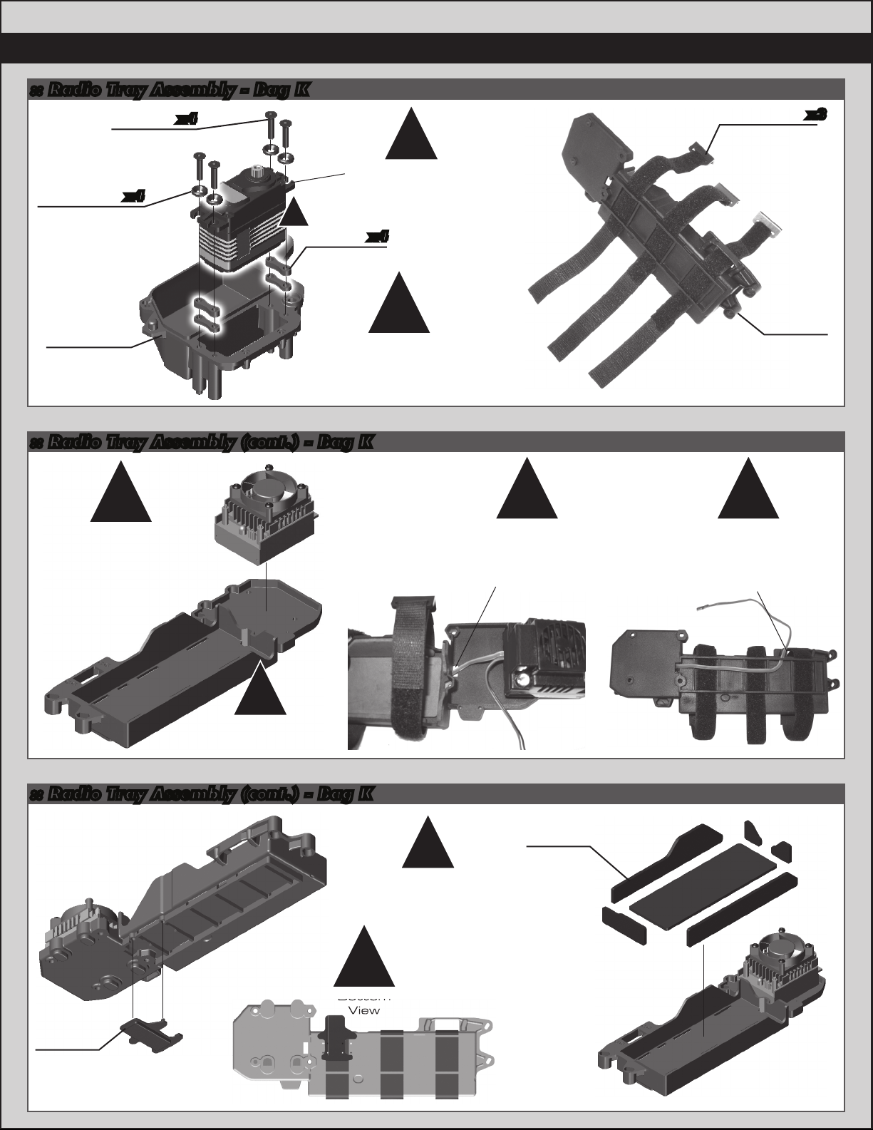
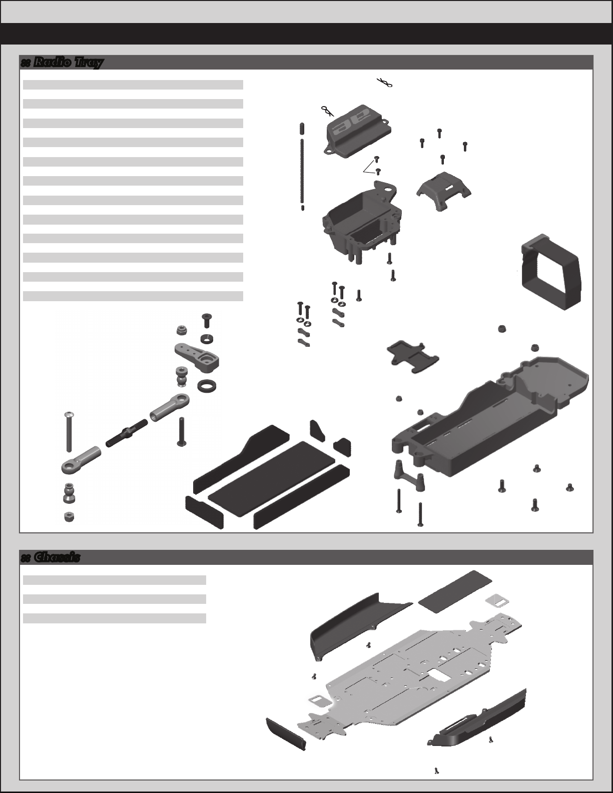
:: Radio Tray Assembly - Bag K
View
89208
3x14mm
89229
Countersunk
washers
(blue)
fhcs
x4
x4
!
89006
Servo
spacers
!
Note: servo
not included.
x4
27
89506
Hook and
loop battery
straps
x3
89504
Radio
tray
(bottom)
Servo mounts vary per
servo manufacturer.
Space your servos low
to the chassis without
touching the bottom.
:: Radio Tray Assembly (cont.) - Bag K
!
Note: speed control
not included.
Attatch with servo
tape #6727.
!
Note: hook and loop
straps are removed
for view clarity.
!
! !
Note: route the
speed control
receiver wire
through this
opening.
89505
RC8e
battery
tray
Note: route the
speed control
receiver wire
through this
opening.
:: Radio Tray Assembly (cont.) - Bag K
89509
Flywheel
opening
cover
!
Note: hook and loop
straps are removed
for view clarity.
!
Bottom
View
89507
Battery
tray pads
Page 28

28
:: Radio Tray Assembly (cont.) - Bag K
25215
M3
locknut
x2
89216
M4
locknut
x2
!
Note: there are two
different positions
for the locknuts
depending on what
vehicle you have.
89509
Battery
tray post
Note: hook and loop
straps are removed
for view clarity.
:: Radio Tray Assembly (cont.) - Bag K
89222
2.5x8mm
shcs
x4
!
!
Note: the cutout
on the battery tray
bridge is facing the
battery tray!
!
Note: hook and loop
straps are removed
for view clarity.
RC8Te
SC8e
RC8Te
SC8e
RC8Te
SC8e
RC8.2e
RC8Te
SC8e
RC8.2e
RC8.2e
RC8.2e
Front
Front
:: Radio Tray Assembly (cont.) - Bag K
!
Note: route the speed
control receiver wire up
and over the bridge
!
Note: route the speed
control receiver wire
through the radio box
hole.
Page 29
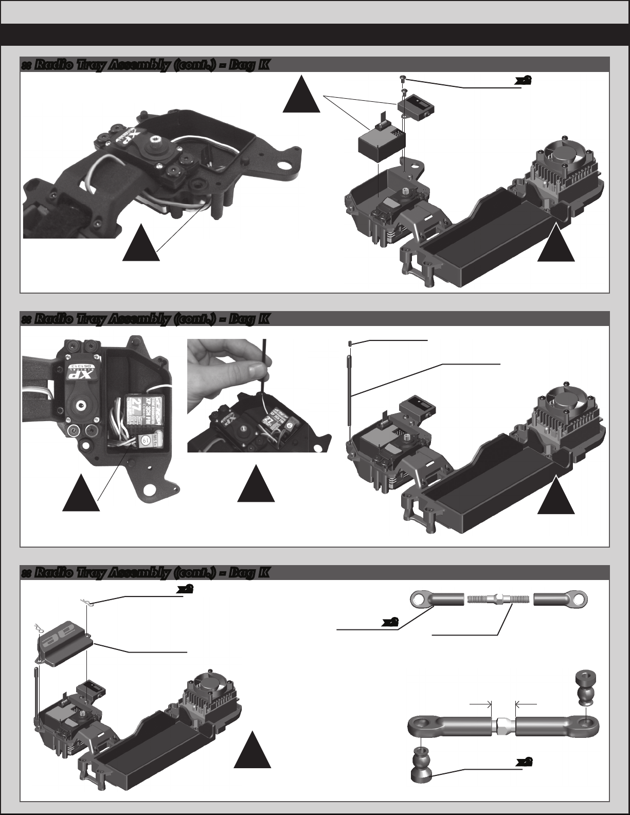
:: Radio Tray Assembly (cont.) - Bag K
Note: receiver and
!
transponder not
included.
31531
3x6mm
bhcs
29
x2
!
Note: route the servo
wire to the receiver
through this opening.
:: Radio Tray Assembly (cont.) - Bag K
!
!
Note: plug in your
speed control and
servo to your receiver.
Note: route your receiver’s
antenna wire through the
slot in the radio tray, and
through your antenna tube.
89219
3x5mm
setscrew
!
Note: hook and loop
straps are removed
for view clarity.
6338
Antenna
tube and
cap
!
Note: hook and loop
straps are removed
for view clarity.
:: Radio Tray Assembly (cont.) - Bag K
21173
Small
body clip
89504
Radio tray
(top)
x2
!
Note: hook and loop
straps are removed
for view clarity.
89078
Straight
eyelet
x2
89267
32mm steel
turnbuckle
8mm
89078
balljoint
x2
Page 30
30
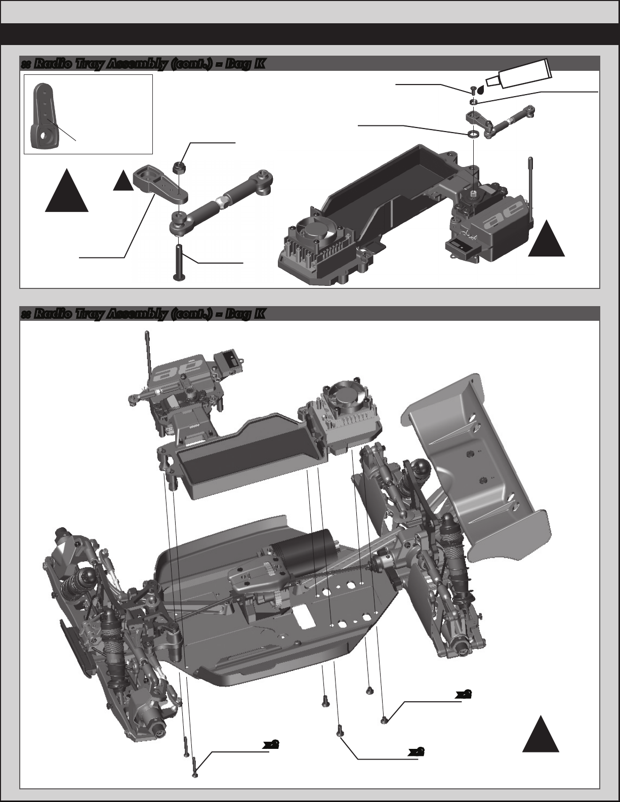
:: Radio Tray Assembly (cont.) - Bag K
A - Airtronics
F - Futaba
H - Hitec
J - JR
Printed here
25215
M3
locknut
!
!
Enlarge holes
in servo horn!
89007
Steering
servo horn
:: Radio Tray Assembly (cont.) - Bag K
2308
3x18mm
bhcs
89007
Servo
horn ring
25201
3x8mm
fhcs
#1596
thread lock
89007
Servo cone
washer
!
Note: hook and loop
straps are removed
for view clarity.
89211
3x26mm
fhcs
x2
89214
4x12mm
fhcs
89213
4x6mm
fhcs
x2
x2
!
Note: hook and loop
straps are removed
for view clarity.
Page 31
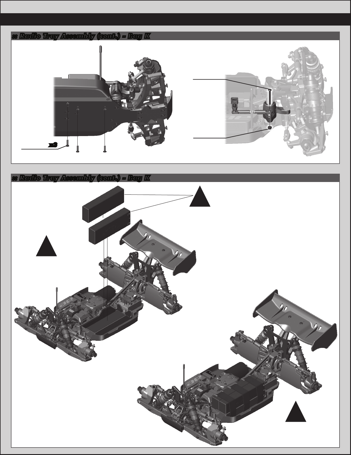
:: Radio Tray Assembly (cont.) - Bag K
25203
3x12mm
fhcs
:: Radio Tray Assembly (cont.) - Bag K
x3
31
89205
3x26mm
bhcs
25215
M3
locknut
!
Batteries are not
included in kit.
!
Note: hook and loop
straps are removed
for view clarity.
!
Note: batteries
not included.
!
Note: strap on
the hook and loop
straps.
Page 32

32
:: Wheels, Tires, and Body Install - Bag L
!
Note: tires and
inserts not included
in kit.
#1597
CA tire glue
:: Wheels, Tires, and Body Install (cont.) - Bag L
Jconcepts
Illuzion RC8.2e
Punisher body
# - 0224
(sold @jconcepts.net)
31531
3x6mm
bhcs
2208
Large
hood
pins
89296
83mm
wheel
(white)
x2
x4
Tires: (not included in kit)
Your tires need to be glued to the
wheels using a fast-curing Tire glue
(CA) (AE Pt#1597). This is available
at your local hobby shop. Make sure
to clean the mounting surface of the
tire with alchohol for best adhesion.
Body :
Your RC8.2e comes with a clear
polycarbonate body. You will need to
prep the body before you can paint
it. Wash the inside thoroughly with
warm water and liquid detergent.
Dry using a clean, soft, lint-free
cloth. Use the supplied window
masks to cover the windows from
the INSIDE. Using high quality tape,
apply to create a design to the
inside of the body. Spray (either can
or airbrush) the paint to the inside
of the body (NOTE: use ONLY paint
that is recommended for use with
(polycarbonate) plastics. If you don’t,
you will destroy the plastic body!!!!).
(RC cars get painted from the inside).
After painting, cut the body along
the trim lines. Make sure to cut
holes for the engine head, body
mounts, antenna, fuel tank lid, top
end adjustment needle and muffler
outlet.
89094
Wheel
hex nuts
x4
Page 33
33
:: Chassis Tips
Gearing:
Follow your motor manufacturer’s recommendations for gearing options.
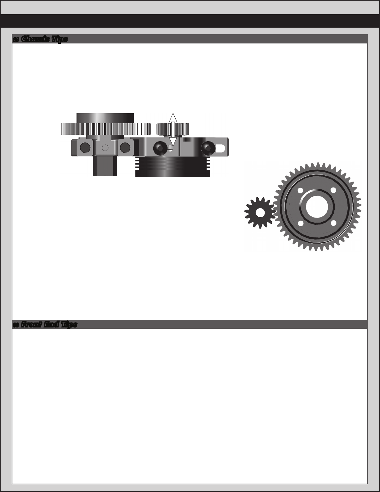
Gear Mesh:
To correctly set your gear mesh, follow the steps below:
1. Loosen the set screw on the motor’s pinion gear. The set screw can be accessed through the slot on the side of the
motor mount slide, opposite the spur gear. Slide the pinion on the motor shaft until the gear face of the pinion is entirely
aligned with the gear face of the spur gear (see diagram). Tighten the set screw while ensuring it is aligned with the flat
face on the motor shaf t.
Spur Gear
2. Loosen the two motor mount slide screws until the slide is able to move
freely. Slide the motor as far as it can go towards the spur gear, ensuring
that the teeth of the pinion and the spur gear are interlocking.
Back the motor mount slide off a tiny bit (approximately 0.5 mm), and tighten
the screws that lock the motor mount in place. Proper gear mesh has been
achieved when the teeth are meshing closely, but the gears still have a small
amount of play between them. If you hold one gear, you should be able to rock
the other gear back and forth a small amount. If there is not “free play”, your
gear mesh is too tight and you should back off the motor a little farther.
Pinion
Pinion
Spur Gear
Differential Fluid:
Team Associated includes a complete bottle of 5,000cst diff oil. You can also provide your own oil and try one of the
optional setups.
Standard differential fluid setup: Front = 5,000cst; Center = 5,000cst; Rear = 5,000cst.
Optional diff setup 1 (high grip track): Front = 5,000cst; Center = 10,000cst; Rear = 5,000cst.
Center Differential:
Use the standard setup for most cases. Some racers will try thicker oil (7,000-10,000cst) when greater acceleration
is needed. This is typically done on very smooth tracks since thicker fluid can reduce handling in bumpy conditions.
:: Front End Tips
Front Differential:
Use the standard setup for most cases. Try 7,000cst to 10,000cst to get less low speed steering and better
acceleration out of turns.
Kickup Bushing:
Generally more kick-up will provide better handling in the bumps and have better straight line acceleration.
Less kick-up will provide more all around steering and have a more aggressive feel.
Caster:
The standard caster block insert setup is for 16 degrees. The standard inboard kick-up is 9 degrees (2-dot up insert
in A-plate). You can reduce the caster using 14 degree inserts (also move both upper cone washers in front of the ball
joint) for smoother steering. Changing to 18 degree inserts (also move both upper cone washers behind the ball joint)
will typically provide more steering on power but reduce handling in bumpy conditions.
Front Upper Pivot Insert:
The standard setup is to use 2-dot up in the tower and 1-dot in the top plate. It is recommended to maintain a 1 dot
gap (1mm per dot) front to rear when using 2-dot up in the A-Plate. Reducing the A-Plate insert to 1-dot allows the use
of same dot number insert in both tower and top plate. Going up to 3-dot up in the tower will give more turn in, but less
steering on power/exit. Going down (1-dot, 2-dot down) will reduce turn in, but give more steering on exit.
Front Camber Link-Outer:
The standard short location will work the best for most tracks. Going to the long front link will give you more steering,
but can make the car less predictable in bumps and exiting turns.
Page 34

34
:: Front End Tips (cont.)
Front Camber Angle:
A good starting camber setting is –2 degrees. Positive camber, where the top of the tire is leaning out, is typically not
recommended.
Front Toe-In:
Zero degree toe-in (tires pointing straight forward) is a good starting setting. You can increase turn in by adding 1-2
degrees of toe-out (front of tires point slightly out). Front toe - in is not a typical tuning adjustment used by the Team.
Front Ride Height:
The front ride height setting you should use most often is with 29mm of gap between the chassis bottom and the
ground. Check the ride height with the FT Ride Height Gauge (#1449) by lifting up the entire vehicle about 8-12 inches
off the bench and drop it. After the suspension “settles” into place, then raise or lower the adjustment collars as
necessary and recheck.
Front Arm Shock Location:
Inside on the arm will give a more responsive front end. Outside on the arm will be less responsive steering, but will be
more predictable through bumps.
:: Rear End Tips
Rear Differential:
Start with the standard setup. For expert drivers, the most popular setting for buggy is 3,000 cst. the thicker
5,000cst kit oil will rotate less in the turns and accelerate straight on power. The thinner oil (2,000 or 3,000cst) will
give more low speed traction.
Anti-squat:
Anti-squat denotes the angel of the rear inner hinge pin relative to the ground. This setting is adjusted by changing the
insert bushing in the C-Plate. The kit setting is 2 degrees (2-dot down) but you change to 1 degree (3-dot down). Typically
less anti-squat lets the suspension work more over the bumps, but it will sacrifice the ability to square up on power.
Rear Camber Link Length & Vertical Adjustment:
You can change the length of the camber link on the hub or tower as well as adjust the vertical location on the tower.
A longer link will give the feeling of the most grip, but it will not be as responsive to square up on throttle, and might get
loose if driven hard. This can easily be corrected by running the shorter link on the hub, but it will sacrifice some forward
grip.
Changing to a higher location on the tower will be a smaller adjustment than changing the length of the upper link.
Going up on the tower location has a similar effect as a longer camber link, but not as drastic. For example, if you change
to the short rear link on the hub and you need to gain more forward grip, try raising the link up on the tower. New
additional lower holes should be used when running the optional hinge pin hole in the rear hub carrier.
Rear Hub Hinge Pin Height:
The upper hole gives more rear grip on turn in, and good forward traction, but it might have difficulty squaring up out of
turns. The lower hinge pin hole in the hub will be more responsive on throttle, and give more side grip in the turns.
Rear Hub Spacing:
You have 3 options for rear hub spacing, FWD, MIDDLE, & BACK. The kit setting provides a good balance of rear
traction and steering, and will be used most often. Moving the hubs FWD will give more rear traction for low grip tracks.
You can use the hubs BACK on high grip tracks for more on-power steering. Also, you can replace the included shims to
get intermediate settings.
Rear Camber:
A good starting camber setting is –2 degrees. Use the included #1719 camber gauge to set your camber. Adding a
small amount of positive camber, where the top of the tire is leaning out, will tend to improve straight-line acceleration on
loose tracks.
Rear Ride Height:
The rear ride height setting you should use most often is 29mm of gap between the chassis bottom and ground.
Check the ride height with the FT Ride Height Gauge (#1449) by lifting up the entire vehicle about 8-12 inches off the
bench and drop it. After the suspension “settles” into place, then raise or lower the adjustment collars as necessary
and recheck.
Rear Arm Shock Location:
Inside on the arm will give less entry steering, accelerates better straightline through bumps, but may lack side bite.
Outside on the arm will be less grip, more steering, but will be more predictable when it breaks traction.
Page 35

:: Droop Settings (Truggy shown but applicable for all vehicles)
35
Step 1:
your working surface so the arms are at full extension, you should be able to easily slide the top of your shock over the
standoff screw, while leaving the shock at full extension. If the mounting hole of the shock cap is above or below the
standoff screw, adjust the droop screw accordingly. Repeat for all corners of your vehicle. Measure from the center of
the standoff screw to the center of the shock riser button to get your FULL DROOP setting.The front shocks should be
109mm, while the rear shocks should be 127.5mm.
Step 2: Finish installing the shock to the standoff.
Set your vehicle to your desired droop setting.
To increase your droop turn the droop screw (from the
top) counter-clockwise (loosen), turn the droop screw
(from the top) clockwise (tighten) to decrease your
droop. Remember, never back the screw out beyond
full droop or you could risk damage to your vehicle.
With only the bottom of the shocks attatched, the droop screws raised all the way, and the chassis above
Step 3: Measure from the center of the shock
standoff screw to the center of the shock riser button
to get your final droop setting. The front shocks should
both be set at the same lenght, as should the rear
shocks. * The normal droop setting is between 0-5mm
from the FULL DROOP measurement.
Front Droop: Increasing front droop (loosen droop screws) will increase off-throttle steering. It also allows the
front end to lift more, giving more rear grip and less front grip on-power. Remember to never loosen the screws beyond
the FULL DROOP setting. Decreasing front droop (tighten droop screws) yields more on-power steering and quicker
response at the expense of some stability in bumpy sections. It will also give less off-throttle steering.
Rear Droop: Increasing rear droop (loosen droop screws) will increase traction in bumpy sections, but will reduce
high-speed stability. Remember to never loosen the screws beyond the FULL DROOP setting. Decreasing rear droop
(tighten droop screws) will increase stability in high speed sections, but will reduce stability in bumpy sections.
Setup Sheets:
Most often the best way to get your car handling right is to go to our website www.rc10.com and click on the
“Setup Sheets” link, then the link to your vehicle, then search for your vehicle. Our team of professional drivers help
develop these setups at National events. Also, most drivers have a “base” setup that they use as a starting point for every event. Try running some of our base setups OR look for track conditions and tires that are similar to your local track
and mimic that setup. Remember, each adjustment has a purpose, so copy everything from the setup sheet and then
make adjustments based on the recommendations in here at http://www.rc10.com/rc/tuning.
Page 36
36
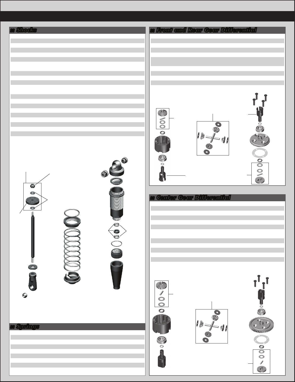
:: Shocks
25612
89066
89067
89083
89215
89278
89290
89291
89335
89344
89346
89351
89352
89353
89354
89355
89469
89492
89554
89555
89556
M3 Locknut With Flange
Shock O-Rings
Shock Limiters, Set
Shock Bushings
Piston Locknut
2.5mm Washer
16x29mm Front Shock Kit requires #89554 shock shafts for RC8.2
16x29mm Front Shock Body
16mm Shock Caps
16x38mm Rear Shock Body
16x38mm Rear Shock Kit requires #89554 shock shafts for RC8.2
16mm Shock Bladders
16mm Shock Rebuild Kit
16mm Shock Pistons
16mm Shock Spring Cups
16mm Shock Collars
HD Shock Ends
16mm Piston 5x1.1 + 5x1.2
HD Shock Shaft, 4x26mm
HD Shock Shaft, 4x36mm
RC8.2 Shock Boots (Front and Rear)
89353
89215
25612
2 ea.
89083
89335
89351
:: Front and Rear Gear Differential
20
10
20
Pr.
Pr.
Pr.
Pr.
25236
89115
8
89116
1
89117
4
89120
89121
1
89208
89477
89478
2
89494
1
8
1
8
4
2
4
4
8x16x5 Bearings
Diff Housing
Diff Gasket
Diff Shims
Diff Sun/Planet Gears, Includes
Washers and Pins, Set
Diff 0-Rings, Big and Small, Set
3x14mm FHCS
RC8B Light Outdrive, Front
RC8B Light Outdrives, Rear
RC8B Light Diff Ring Gear, Includes Diff Gasket
89120
89120
89121
89115
25236
89121
Front
89477
Rear
89478
89208
Front
89477
Rear
89478
89494
89116
89121
89120
2
1
4
8
1
1
10
2
2
1
89208
89121
25236
89492
89469
:: Springs
89541
89542
89543
89544
89545
89546
89547
89548
RC8.2 Front Spring Kit
RC8.2 Front Spring Green (4.0lbs)
RC8.2 Front Spring Silver (4.3lbs) - Kit
RC8.2 Front Spring Blue (4.65lbs)
RC8.2 Rear Spring Kit
RC8.2 Rear Spring Green (3.25 lbs)
RC8.2 Rear Spring Silver (3.55 lbs) - Kit
RC8.2 Rear Spring Blue (3.75 lbs)
89278
Front
89554
Rear
89555
89352
89469
89352
89354
89355
89352
Front
89543
Rear
89547
Front
89291
Rear
89344
89066
89352
89352
89556
:: Center Gear Differential
25236
89109
89110
89115
89116
89119
89120
89121
89208
89519
89520
89521
1
Pr.
Pr.
Pr.
1
Pr.
Pr.
Pr.
8x16x5 Bearings
Spur Gear 44T, Includes Diff Gasket
Spur Gear 46T, Includes Diff Gasket
Diff Housing
Diff Gasket
Center Diff Outdrives
Diff Sun/Planet Gears, Includes
Washers and Pins, Set
Diff 0-Rings, Big and Small, Set
3x14mm FHCS
Plastic Spur Gear 46T, Includes Diff Gasket - Kit
Plastic Spur Gear 48T, Includes Diff Gasket
Plastic Spur Gear 50T, Includes Diff Gasket
89120
89121
89115
25236
89121
89119
2
1
1
1
4
2
1
1
10
1
1
1
1
89208
89208
89119
89120
89121
25236
89519
89116
89121
89120
Page 37

37
:: Shock Fluid
5420
5421
5422
5423
5424
5425
5426
5427
5428
5429
5430
5431
5432
5433
5434
5435
5436
5437
5438
10 Weight Silicone Shock Fluid
20 Weight Silicone Shock Fluid
30 Weight Silicone Shock Fluid
40 Weight Silicone Shock Fluid
22.5 Weight Silicone Shock Fluid
80 Weight Silicone Shock Fluid
27.5 Weight Silicone Shock Fluid
15 Weight Silicone Shock Fluid
25 Weight Silicone Shock Fluid
35 Weight Silicone Shock Fluid
45 Weight Silicone Shock Fluid
55 Weight Silicone Shock Fluid
32.5 Weight Silicone Shock Fluid
37.5 Weight Silicone Shock Fluid
42.5 Weight Silicone Shock Fluid
50 Weight Silicone Shock Fluid
60 Weight Silicone Shock Fluid
70 Weight Silicone Shock Fluid
47.5 Weight Silicone Shock Fluid
2oz.
2oz.
2oz.
2oz.
2oz.
2oz.
2oz.
2oz.
2oz.
2oz.
2oz.
2oz.
2oz.
2oz.
2oz.
2oz.
2oz.
2oz.
2oz.
:: Lubes & Adhesives / Decals / Misc.
1105
1596
1597
5450
5451
5452
5453
5454
5455
5456
5457
5458
5459
6588
6591
6636
6727
716
717
3816
3820
3834
89559
FT Green Slime Shock Lube
FT Locking Adhesive
FT Tire Adhesive, Medium
Silicone Diff Fluid 1000cst
Silicone Diff Fluid 2000cst
Silicone Diff Fluid 3000cst
Silicone Diff Fluid 5000cst
Silicone Diff Fluid 7000cst
Silicone Diff Fluid 10000cst
Silicone Diff Fluid 20000cst
Silicone Diff Fluid 30000cst
Silicone Diff Fluid 60000cst
Silicone Diff Fluid 100000cst
Black Grease - 4cc
S.Diff Lube - 4cc
Silicone Grease - 4cc
Servo Tape
Reedy 2009 Sticker Set
Reedy Powered Logo Decal
American Bumper Sticker
AE Logo Decal Sheet
AE Blue Embossed Logo Sticker
RC8.2 Decal Sheet
1
1
1
1
1
1
1
1
1
1
1
1
1
1
1
1
2
1
1
1
1
2
1
:: Center CVA’s
89103
89106
89221
89286
89557
89560
RC8 Center CVA Bone
RC8 Center CVA Rebuild Set
5x4mm Setscrew
RC8 Gearbox Input Cup, Aluminum
Pin Retainer O-Ring / Boot
RC8 Rear Center Drive Shaft +3mm
Front Rear
89106
89286
89103
89221
89106
89557
89560
89106
89286
89106
2
1
10
2
2 ea.
1
89221
89557
:: Top Plate
25202
89011
89039
89214
89227
89234
89236
89455
3x10mm FHCS
RC8 Body Mounts, Set
Hinge Pin Bushings, 1/2/3 dot, Set
4x12mm FHCS
3x28mm SHCS
Blue Aluminum Top Plate - Kit
Black Aluminum Top Plate (FT)
3x22mm FHCS
89455
89227
89039
:: Steering
25215
31404
89014
89015
89016
89117
89161
89214
89242
89455
89485
89455
M3 Locknut
6x10mm Bearing
Steering Rack Post
Servo Saver, Set
Servo Saver Bolt, Nut, Spring, Set
Diff Shims
Steering Bearing Set
4x12mm FHCS
Steering Drag Link
3x22mm FHCS
Aluminum Steering Posts
25215
89242
89455
89039
25215
89214
89016
89014
89161
89015
89015
89161
89117
89016
89117
89016
20
1
1
10
10
1
1
10
89011
89214
89234
89236
25202
20
2
2
1
1
8
1
10
1
10
2
31404
31404
89014
89161
89015
89161
31404
89485
89214
31404
89485
89557
89557
89214
Page 38
38
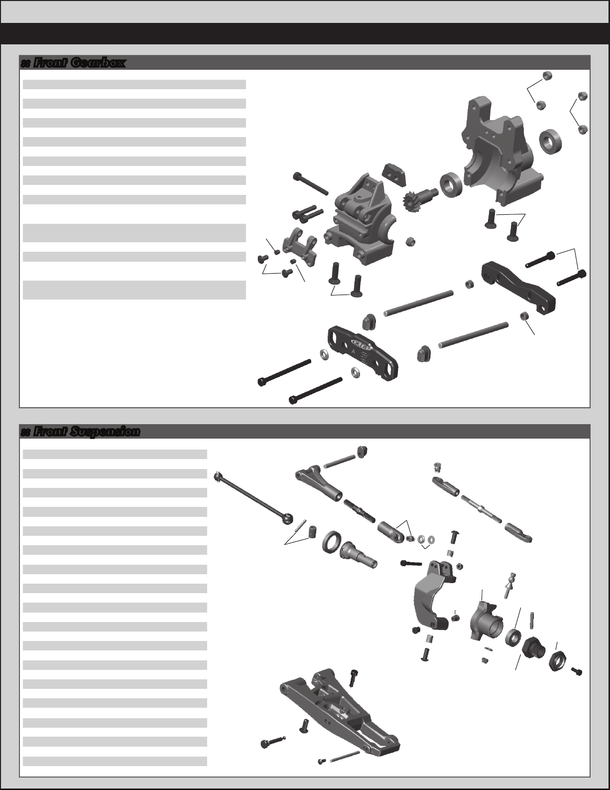
:: Front Gearbox
25215
25236
31531
89017
89039
89114
89214
89217
89219
89224
89227
89230
89279
89460
89461
89466
89472
89474
89481
89482
89553
M3 Locknut
8x16x5 Bearing
3x6mm BHCS
FR/RR Gearbox
Hinge Pin Bushings, Set
Diff Pinion Gear
4x12mm FHCS
4x14mm FHCS
3x5mm Setscrew
3x16mm SHCS
3x28mm SHCS
Silver Cone Washer
3x45mm SHCS
RC8 Aluminum A-Plate
RC8 Aluminum B-Plate w/Pins, Set
works with #89466
RC8B Inner Hinge Pins, 4mm-HMA, Set
works with #89461
RC8B Front Bulkhead Spacer
3x22mm FHCS
RC8B Low B Plate - Kit
works with #89482, 89553
RC8B Low B Plate Inserts - Kit
works with #89481, 89553
RC8.2 FR Hinge Pins, TiN - Kit
works with #89481, 89482
20
2
10
1
1
1
10
10
10
10
10
10
10
1
1
1
1
10
1
2
2
89224
89219
31531
89227
89219
89217
89460
89230
89017
89039
89472
89017
89017
89114
25215
89482
89553
25236
89553
25215
25215
25236
89214
89474
89481
89482
:: Front Suspension
25215
25236
31520
89029
89032
89039
89040
89041
89074
89075
89076
89077
89094
89095
89096
89102
89105
89162
89206
89207
89218
89223
89225
89230
89269
89285
89317
89380
89454
89526
89549
89550
89558
91069
M3 Locknut
8x16x5 Bearing
2.5x6mm BHCS
Steering Block Bushings, Set
Caster Angle Bushings, Set
Hinge Pin Bushings, Set
RC8 Inner Hinge Pins, Set
RC8 Outer Hinge Pins, Set
Steering Rod Ends
RC8 Steering Ballstuds
RC8 Camber Rod Ends, Set
Chassis Brace Rod Ends, Set
Nyloc Wheel Hex Nuts (Blue)
RC8 Wheel Hex (Aluminum)
RC8 Wheel Hex Pins
RC8 Front/Rear CVA Bone
RC8 CVA Rebuild FR/RR, Set
15x21x4 Bearing
4x10mm BHCS
4x12mm BHCS
3x8mm Washer
3x8mm SHCS
3x24mm SHCS
Silver Cone Washer
Steel turnbuckle, 38mm
Front Stub Axle, Aluminum
RC8T Droop Screws
FT Machined Steering Blocks
3x12mm SHCS
50mm Steel Turnbuckle
RC8.2 Front Upper Arms
RC8.2 Front Arms
RC8.2 Caster Blocks
Shock Mount Pin, Steel
20
2
6
1
1
1
1
1
4
4
1
1
4
Pr.
4
2
1
2
10
10
10
10
10
10
2
2
8
Pr.
10
2
Pr.
Pr.
Pr.
4
89279
89102
91069
89279
89549
89105
89317
31520
89230
89040
89162
89285
89041
89039
89269
89558
89032
89207
89454
89550
89076
89230
89225
89029
89039
89077
89032
89218
25215
89074
89206
89029
25215
89380
89526
25236
89095
89074
89075
89096
89094
89223
Page 39
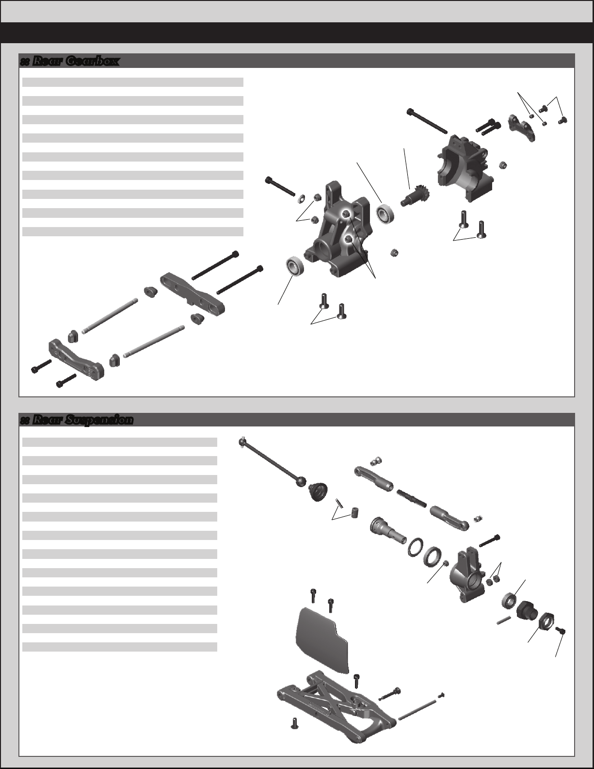
:: Rear Gearbox
25191
25215
25236
31531
89017
89039
89114
89214
89217
89219
89224
89227
89228
89230
89452
89462
89463
89466
3x18mm SHCS
M3 Locknut
8x16x5 Bearing
3x6mm BHCS
RC8 FR/RR Gearbox, Set
RC8 Hinge Pin Bushings, Set
RC8 Diff Pinion Gear
4x12mm FHCS
4x14mm FHCS
3x5mm Setscrew
3x16mm SHCS
3x28mm SHCS
3x40mm SHCS
Silver Cone Washer
3x50mm SHCS
RC8 Aluminum C - Plate
RC8 Aluminum D - Plate w/Pins, Set
RC8B Inner Hinge Pins, 4mm HMA, Set
89039
89466
89463
89452
20
20
2
6
1
1
1
10
10
10
10
10
10
10
10
1
1
1
89452
89227
89230
25215
89017
25236
25236
25215
89228
89114
25215
89224
89217
89219
25215
89017
39
31531
89017
89039
25191
25191
89039
89462
:: Rear Suspension
25215
25236
31520
89031
89033
89041
89076
89094
89095
89096
89102
89105
89107
89162
89219
89223
89269
89284
89317
89454
89474
89551
89561
91069
M3 Locknut
8x16x5 Bearings
2.5x6mm BHCS
RC8 Caster/Hub Spacers, Set
RC8 Hub Carriers
RC8 Outer Hinge Pins, Set
RC8 Camber Rod Ends, Set
Nyloc Wheel Hex Nuts (Blue)
RC8 Wheel Hex (Aluminum)
RC8 Wheel Hex Pins
RC8 Front/Rear CVA Bone
RC8 CVA Rebuild FR/RR, Set
RC8 Rear CVA Shield/Boot, Set
15x21x4 Bearing
3x5mm Setscrew
3x8mm SHCS
38mm Steel Turnbuckle
Rear Stub Axle, Aluminum
RC8T Droop Screws
3x12mm SHCS
3x22mm SHCS
RC8.2 Rear Arms
Rear Mud Guards
Shock Mount Pin, Steel
89466
89039
20
2
6
1
Pr.
1
1
4
Pr.
4
2
1
1
2
10
10
2
2
8
10
10
Pr.
Pr.
4
89102
89561
89551
89214
89107
89105
89454
89284
89454
89076
89076
89107
89162
89454
89269
25215
91069
89076
89033
31520
89076
89474
89031
25236
89095
89096
89094
89223
89317
89041
Page 40

40
Rear
:: Front Shock Tower :: Rear Shock Tower
31531
89218
89225
89230
89454
89470
89473
89538
3x6mm BHCS
3x8mm Washer
3x24mm SHCS
Silver Cone Washer
3x12mm SHCS
RC8B Shock Tower Hinge Pin Bushings, Set
RC8B Steel Shock Stand-offs
RC8.2 Front Tower, Aluminum
89230
89225
89538
10
10
10
10
25192
6
25215
25620
89011
89225
89230
1
89454
4
89473
1
89539
3x20mm SHCS
M3 Locknut
3x10mm SHCS
RC8 Body Mounts, Set
3x24mm SHCS
Silver Cone Washer
3x12mm SHCS
RC8 Steel Shock Standoffs
RC8.2 Rear Tower, Aluminum
20
20
20
1
10
10
10
4
1
89473
89218
89470
89454
31531
89454
89454
89454
:: Center Bulkhead
25223
89019
89207
89214
89217
89226
89254
89454
89502
89503
89512
89513
89514
89515
89516
89517
89529
4x3mm Setscrew (for use with pinions)
RC8 Center Bulkhead, Set
4x12mm BHCS
4x12mm FHCS
4x14mm FHCS
3x26mm SHCS
Center Top Plate
3x12mm SHCS
Center Diff Riser
RC8.2e FT Motor Mount Washers
RC8e 12T Pinion
RC8e 13T Pinion
RC8e 14T Pinion
RC8e 15T Pinion
RC8e 16T Pinion
RC8e 17T Pinion
RC8.2e FT Motor Mount Set
31531
89470
89218
89225
89230
89473
89473
25620
25192
20
1
10
10
10
10
1
10
1
10
1
1
1
1
1
1
1
89454
89454
:: Chassis Braces
25215
89068
89069
89077
89209
89238
89239
89258
89225
89230
25215
89539
89230
89230
25192
M3 Locknut
RC8 Pivot Chassis Brace Set (Front)
RC8 Pivot Chassis Brace Set (Rear)
Chassis Brace Rod Ends, Set
works with #89068, 89069
3x18mm FHCS
FT Aluminum Chassis Brace (Front)
FT Aluminum Chassis Brace (Rear)
RC8 Chassis Braces, Plastic - Kit
(Front, Rear)
89011
89225
89230
25215
89473
20
1
1
1
10
1
1
1
89226
89019
89226
89254
89019
89503
89529
89454
89454
89207
89217
89207
89503
89529
89019
89502
89214
25215
Rear
89209
89258
Front
89258
25215
89209
Page 41
:: Radio Tray
2308
6338
21173
25201
25203
25215
31531
89006
89007
89078
89205
89208
89211
89213
89214
89216
89219
89222
89229
89504
89505
89506
89507
89509
89205
3x18mm BHCS
Antenna Tube and Cap
18T Body Clips
3x8mm FHCS
3x12mm FHCS
M3 Locknut
3x6mm BHCS
RC8 Servo Mount Spacers, Set
Steering Servo Horns, Set
RC8 Servo Link Rod Ends, Set
3x26mm BHCS
3x14mm FHCS
3x26mm FHCS
4x6mm FHCS
4x12mm FHCS
M4 Locknut
3x5mm Setscrew
2.5x8mm SHCS
Blue Countersunk Washers
RC8e Radio Tray
RC8e Battery Tray
Hook and Loop Battery Straps, Set
Battery Tray Pads, Set
Battery Tray Accessories, Set
89267
25215
89078
89078
2308
6
1
12
20
20
20
6
1
1
1
10
10
10
10
10
10
10
10
10
1
1
1
1
1
25201
89007
89007
89007
6338
6338
89219
89208
89229
89006
89006
21173
89208
89229
31531
89006
89006
89504
89222
25203
25215
25215
21173
89222
89504
25203
25203
89222
89509
89505
41
89222
89509
89506
89216
89216
89078
:: Chassis
25201
89018
89022
89476
89510
89552
3x8mm FHCS
Gearbox Gasket
Front Bumper
FT RC8B +3mm Chassis
Motor Pad
RC8.2 Side Guards, Set
89078
25215
20
4
1
1
1
1
89022
89507
25201
89018
89552
89509
89211
25201
89211
89510
89214
89214
89018
25201
89213
89213
89476
89552
25201
Page 42
42
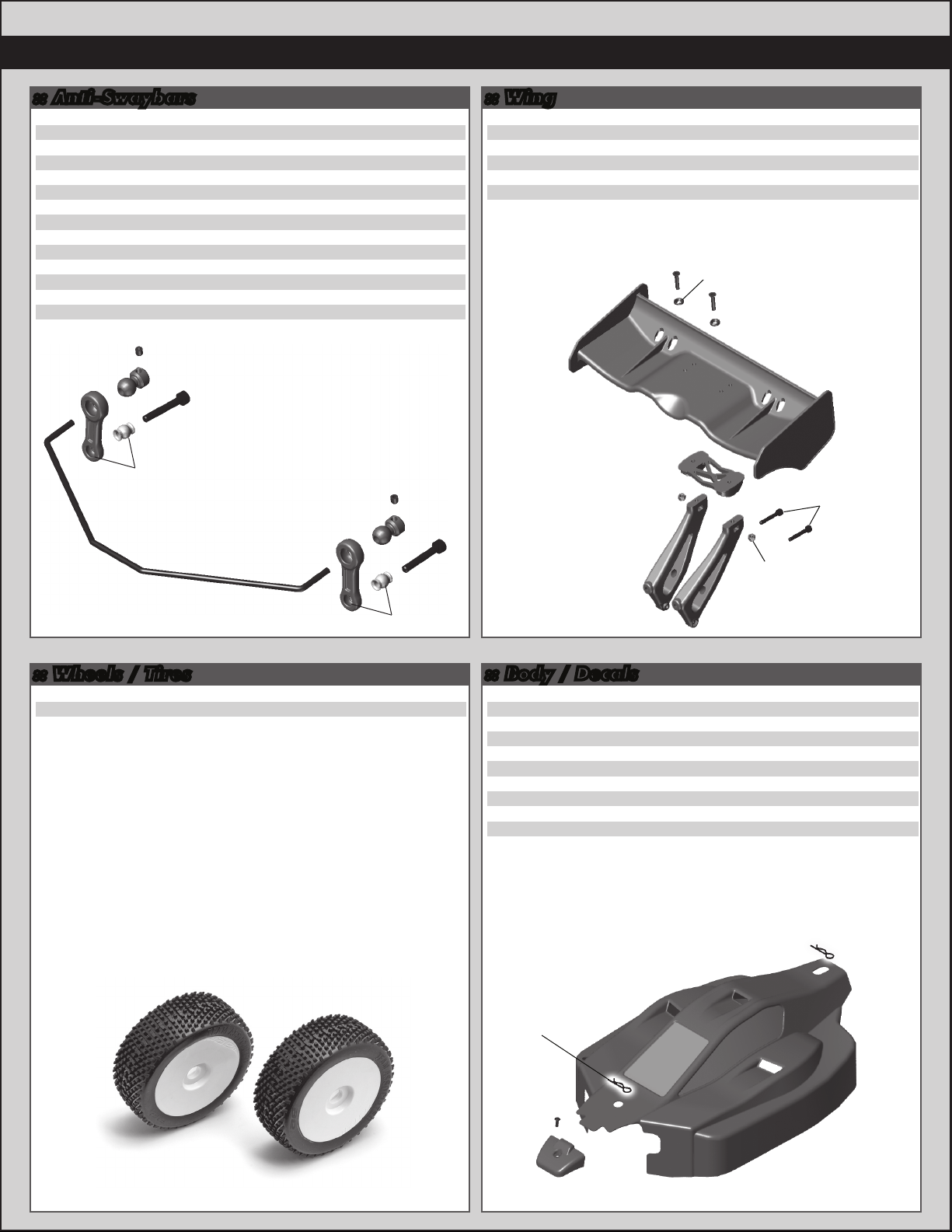
:: Anti-Swaybars
25192
25225
89487
89488
89489
89490
89530
89531
89532
89533
89534
89535
89536
89537
3x20mm SHCS
3x3mm Setscrew
RC8B RR Swaybar, 2.5 (Green) - Kit
RC8B RR Swaybar, 2.6 (White)
RC8B RR Swaybar, 2.7 (Blue)
RC8B RR Swaybar, 2.8 (Yellow)
RC8.2 FR Swaybar Kit
RC8.2 RR Swaybar Kit
RC8.2 FR Swaybar, 2.2 (Green)
RC8.2 FR Swaybar, 2.3 (White) - Kit
RC8.2 FR Swaybar, 2.4 (Blue)
RC8.2 FR Swaybar, 2.5 (Yellow)
RC8.2 Swaybar Pivot Ball
RC8.2 Swaybar Drop Link
25225
89536
25192
89537
89532
89533
89534
89535
Front
Rear
89487
89488
89489
89490
25225
89536
89537
20
20
1
1
1
1
1
1
1
1
1
1
4
4
25192
:: Wing
25192
25204
25215
89229
89304
89540
89304
3x20mm SHCS
3x16mm FHCS
M3 Locknut, (Black)
Blue Countersunk Washer
JC Illuzion Wing (Black)
RC8.2 Wing Mount, Set
25204
89229
89540
25215
89540
20
20
20
10
1
1
25204
89229
25192
25215
89540
:: Wheels / Tires
89255
89296
89297
RTR Pre-Glued Wheel/Tire (White)
RC8 83mm Wheels (White) - Kit
RC8 83mm Wheels (Yellow)
89255
:: Body / Decals
Pr.
1737
2208
4
31531
4
89150
89275
89276
89277
89475
89508
89523
89559
2208
31531
FT Body Scissors
Large Hood Pins
3x6mm BHCS
RC8 Body w/Window Mask (Clear)
RC8 RTR Body (Black)
RC8 RTR Body (White)
RC8 RTR Body Wrap Decals
RC8B Decal Sheet
RC8.2e FT Decal Sheet
RC8e Body w/Window Masks (Clear)
RC8.2 Decal Sheet
89523
1
6
6
1
1
1
1
1
1
1
1
2208
Page 43
43
:: Factory Team and Option Parts
25392
80930
89005
89012
89016
89020
89045
89068
89069
89070
89071
89073
89081
89082
89084
89085
89161
89229
89234
89235
89236
89237
89238
89239
89284
89285
89286
89380
89381
89405
89406
89456
89460
89461
89462
89463
89464
89465
89466
89470
89473
89476
89477
89478
89481
89482
89483
89484
89485
3mm Blue Locknut, Flanged
1/8 Scale Electric Conversion Kit
Aluminum Antenna Mount
RC8 Steering Rack, Carbon Fiber
Servo Saver Bolt, Nut, Spring
Center Bulkhead Plate CF
RC8 FT 0.5 Degree Toe Bushing
RC8 Pivot Chassis Brace Set (Front)
RC8 Pivot Chassis Brace Set (Rear)
RC8 Ti Turnbuckle Set
Camber Turnbuckles 5mm
Servo Turnbuckle 4mm
RC8 Rear Shock Tower, Carbon Fiber
RC8 Shock Standoffs, Aluminum
RC8 Front Shock Tower, Billet
RC8 Rear Shock Tower, Billet
Steering Bearing Set
Blue Countersunk Washer
Blue Aluminum Top Plate (FT)
RC8 CNC Aluminum Steering Rack
Black Aluminum Top Plate (FT)
RC8 Skid Plate
FT Aluminum Chassis Brace (Front)
FT Aluminum Chassis Brace (Rear)
RC8 Rear Stub Axle (Aluminum)
RC8 Front Stub Axle (Aluminum)
RC8 Gearbox Input Cup (Aluminum)
RC8 FT Machined Steering Blocks
RC8 FT Machined Rear Hubs
Nyloc Wheel Nuts (Silver)
Nyloc Wheel Nuts (Black)
16mm Piston 10x1.1
RC8 Aluminum A-Plate
RC8 Aluminum B-Plate w/Pins, Set
RC8 Aluminum C-Plate
RC8 Aluminum D-Plate w/Pins, Set
RC8B Aluminum Front Shock Tower
RC8B Aluminum Rear Shock Tower
RC8B Inner Hinge Pins, 4mm HMA, Set
RC8B Shock Tower Hinge Pin Bushings, Set
Steel Shock Standoff
FT RC8B +3mm Chassis
FT RC8B Light Outdrive, Front
FT RC8B Light Outdrive, Rear
FT RC8B Low B-Plate
FT RC8B Low B-Plate Inserts
FT RC8B Front Shock Tower
FT RC8B Rear Shock Tower
FT RC8B Aluminum Steering Posts
:: XP Electronics
29102
1
29107
1
29108
1
29109
1
29110
1
29111
1
29112
1
29113
1
29115
1
29122
1
29123
2
29124
1
29125
1
29126
4
29130
1
29131
1
29132
1
29150
10
1
29156
1
29158
1
29160
1
29161
1
29162
1
29164
2
29165
2
29166
2
29167
Pr.
29170
Pr.
29171
4
29172
4
29173
4
29174
1
29175
1
29176
1
29178
1
29187
1
29189
1
29200
1
29202
1
29206
2
29209
1
29210
2
29211
2
29212
1
29221
2
29222
1
1
2
Antenna (silver) xp2/xp3/xp3d
Metal gear set, S1903/S1903MG
AM TX + RX crystal set, 26.995 Ch 1
AM TX + RX crystal set, 27.045 Ch 2
AM TX + RX crystal set, 27.095 Ch 3
AM TX + RX crystal set, 27.145 Ch 4
AM TX + RX crystal set, 27.195 Ch 5
AM TX + RX crystal set, 27.255 Ch 6
BEC switch with harness, TR-404A
Receiver, AM 27MHZ 2ch, TR202A
Receiver, AM 27MHZ 4ch, TR402A
S1903 standard servo
S1903MG standard servo, metal gear
S2008MG high torque servo, metal gear
Micro receiver, AM 27MHZ 2ch, TR204A
SHV1504 servo
SHV1504MG servo
Charger for xp2/xp3/xp3d & receiver
packs (not for LiPo)
XP3D FM Radio System 75mHz
XP3D 3ch Digital Transmitter Only
Transmitter RF module, AM 27MHZ
Transmitter RF module, FM 27MHZ
Transmitter RF module, FM 75MHZ
Receiver, FM 27MHZ 3ch, TR301F
Receiver, FM 75MHZ 3ch, TR301F
DS1313 performance digital servo
DS1015 hi-torque/hi-speed digital servo
FM TX + RX crystal set, 26.995 Ch 1
FM TX + RX crystal set, 27.045 Ch 2
FM TX + RX crystal set, 27.095 Ch 3
FM TX + RX crystal set, 27.145 Ch 4
FM TX + RX crystal set, 27.195 Ch 5
FM TX + RX crystal set, 27.255 Ch 6
FM TX + RX crystal set, 75.410 Ch 61
FM TX + RX crystal set, 75.450 Ch 63
FM TX + RX crystal set, 75.630 Ch 72
FM TX + RX crystal set, 75.670 Ch 74
FM TX + RX crystal set, 75.890 Ch 85
FM TX + RX crystal set, 75.930 Ch 87
Receiver, AM 27MHZ 4ch, TR405A
Gear set, DS1313 digital servo
Gear set, DS1015 digital servo
Servo case, DS1313/DS1015
Accessory pack
XP3SS 2.4GHz Radio System
TRS401SS 2.4GHz 4Ch Receiver
1
1
1
1
1
1
1
1
1
1
1
1
1
1
1
1
1
1
1
1
1
1
1
1
1
1
1
1
1
1
1
1
1
1
1
1
1
1
1
1
1
1
1
1
1
1
:: LRP Chargers, Soldering Irons
LRP41281
LRP41555
LRP42305
LRP43150
LRP45200
LRP65800
LRP65802
LRP65803
LRP65804
Quadra Pro 2 Charger
Pulsar Touch Competition Charger
Pulsar Touch Temperature Sensor
Power Supply Competition
LiPo Parallel Balancer
High Power Solder Station
Soldering Tip 5mm
Soldering Tip 1.2mm
Soldering Handle
:: LRP 1/8 Brushless Systems
LRP53230
LRP53240
LRP53270
LRP80785
LRP80786
LRP80787
LRP80880
Dynamic 8 Brushless Motor 1800KV
Dynamic 8 Brushless Motor 2200KV
Dynamic 8 Brushless Motor 2600KV
IX8/Dynamic 8 2600KV
IX8/Dynamic 8 2200KV
IX8/Dynamic 8 1800KV
IX8 Brushless ESC
1
1
1
1
1
1
1
1
1
1
1
1
1
1
1
1
Page 44

44
:: Reedy Accessories
604
606
607
654
655
656
657
658
659
715
716
SP35M
SP35L
SP35XL
SP35XXL
SP35XXXL
SP36M
SP36L
SP36XL
SP36XXL
SP36XXXL
526-S AC/DC 2S-6S LiPo/LiFe Charger
Charge Harness 2S Saddle Pack 4mm
Charge Harness 2S Standard Pack 4mm
4.0mm plugs (2M, 2F)
4.0mm plugs (2M, 10F)
4.0mm plugs (10F)
4.0mm plugs (100F)
4.0mm plugs (10M)
4.0mm plugs (30M)
Reedy 2009 Banner
Reedy 09 Decal Set
Reedy Logo T-Shirt - White M
Reedy Logo T-Shirt - White L
Reedy Logo T-Shirt - White XL
Reedy Logo T-Shirt - White XXL
Reedy Logo T-Shirt - White XXXL
Reedy Logo T-Shirt - Black M
Reedy Logo T-Shirt - Black L
Reedy Logo T-Shirt - Black XL
Reedy Logo T-Shirt - Black XXL
Reedy Logo T-Shirt - Black XXXL
:: Reedy Batteries
302
303
626
628
632
633
634
637
709
720
721
722
723
732
733
734
735
AA Alkaline 1.5V (4)
AA 2700mAh NiMH 1.2V Rechargeable
LiPo 60C 5500mAh 14.8V
LiPo 60C 5500mAh 7.4V
TX Lightweight Battery 1350mAh 11.1V
TX Battery - 3PK, M11 3000mAh 11.1V
TX Battery - Helios, Z1 2400mAh 11.1V
TX Battery - M11X 2500mAh 7.4V
LiPo 5000mAh 7.4V 35C ROAR Spec
LiPo 5000mAh 14.8V 40C
LiPo 3100mAh 22.2V 40C
LiPo 3800mAh 18.5V 40C
LiFe 4000mAh 6.6V 30C
Wolfpack LiPo 3400mAh 7.4V 35C w/DEANS®
Wolfpack LiPo 3700mAh 14.8V 35C w/DEANS®
Wolfpack LiPo 6500mAh 7.4V 25C w/DEANS®
Wolfpack LiPo 3900mAh 11.1V 35C w/DEANS®
:: Apparel
SP35**
SP36**
SP62**
SP63**
SP64**
SP65**
SP66**
SP67**
SP69**
SP101
SP102
SP103
SP411S
SP411L
SP416
SP417
SP420**
715
110684
Reedy 09’ White T-Shirt (M, L, XL, 2XL, 3XL)
Reedy 09’ Black T-Shirt (M, L, XL, 2XL, 3XL)
AE Vertigo Long Sleeve T-Shirt (S, M, L, XL, 2XL)
AE Vertigo White T-Shirt (S, M, L, XL, 2XL, 3XL, 4XL)
AE Vertigo Blue T-Shirt (S, M, L, XL, 2XL, 3XL, 4XL)
AE Vertigo Black T-Shirt (S, M, L, XL, 2XL, 3XL, 4XL)
AE Stencil Blue T-Shirt (S, M, L, XL, 2XL, 3XL)
AE Stencil Gray Sweatshirt (S, M, L, XL, 2XL, 3XL)
26-Time World Championship T-shirt, black
(S, M, L, XL, 2XL, 3XL)
1/8 Inner Boxes Only, Set
1/10 Inner and Outer Boxes Only, Set
1/10 Inner Boxes Only, Set
AE Hat 11’ Flatbill Black S/M
AE Hat 11’ Flatbill Black L/XL
1/10 Car Carrier Bag Only
1/10 FT Motor Bag
AE Pit Gloves (M, L, XL)
Reedy 2009 Track Banner
Team Associated Track Banner
:: 1/18 Kits and RTR’s
1
20100
1
20101
1
20103
1
20105
1
20106
1
20110
1
20115
1
20118
1
20120
1
20121
1
20130
1
1
1
1
1
:: 1/12, 1/10 Kits and RTR’s
1
2033
1
2042
1
4019
1
7023
1
7027
7029
7030
7032
1
7034
1
7036
1
7037
1
7046
1
7047
1
7048
1
7049
1
7080
1
7092
1
8020
1
8021
1
9036
1
9039
1
9061
1
20515
1
30105
1
30106
30111
90004
90005
90006
1
90007
1
1
1
1
1
:: 1/8 Kits and RTR’s
1
1
20503
1
20504
1
1
80902
1
80904
1
80905
1
80906
1
80912
1
80922
Pr.
1
80923
1
80924
80925
80932
RC18T RTR (ready-to-run)
RC18T2 2.4ghz RTR (ready-to-run)
RC18B2 - RC18T2 Team Kit
RC18B RTR (ready-to-run)
RC18B2 2.4ghz RTR (ready-to-run)
RC18MT RTR (ready-to-run)
RC18R Kamino RTR (ready-to-run)
RC18R Niteline RTR (ready-to-run)
SC18 RTR (ready-to-run)
SC18 Brushless RTR (ready-to-run)
RC18LM RTR (ready-to-run)
FT Nitro TC3 Kit
Nitro TC3 RTR Plus (ready-to-run)
FT 12R5.1 Kit
RC10T4.1 FT Kit
SC10 2WD Short Course Race Truck Kit
SC10 Associated/RC10.com Truck RTR (ready-to-run)
SC10 KMC Wheels Race Truck RTR (ready-to-run)
SC10 Ready Lift RTR (ready-to-run)
SC10 FT Kit
RC10T4.1 RTR 2.4GHz Brushed (ready-to-run)
RC10T4.1 RTR 2.4GHz Brushless (ready-to-run)
SC10RS RTR, 2.4ghz Brushless Lucas Oil Body
SC10RS RTR, 2.4ghz Brushless Monster Energy Body
SC10RS RTR, 2.4ghz Brushless Pro Comp Body
SC10RS RTR, 2.4ghz Brushless Rockstar/Makita Body
FT GT2 Nitro Truck Kit
GT2 RS Truck Nitro RTR (ready-to-run)
FT RC10R5 Kit
FT RC10R5-OVAL Kit
RC10B4.1 FT Kit
RC10B4.1 RTR 2.4GHz Brushless (ready-to-run)
FT B44.1 4WD Buggy Kit
MGT 3.0 Nitro Monster Truck RTR (ready-to-run)
FT TC5R Rubber Tire Edition 4WD Touring Car Kit
FT TC6 4WD Touring Car Kit
TC4 4WD Touring Car RTR (ready-to-run)
SC10 4X4 Kit
SC10 4X4 RTR, 2.4ghz Brushless Lucas Oil Body
SC10 4X4 RTR, 2.4ghz Brushless Pro Comp Body
SC10 4X4 RTR, 2.4ghz Brushless Rockstar/Makita Body
Limited Edition MGT 4.60 Nitro RTR, w/flag body
(ready-to-run)
Limited Edition MGT 8.0 Nitro RTR, w/flag body
(ready-to-run)
FT RC8B Nitro Buggy Kit
FT RC8Be Electric Buggy Kit
RC8RS “Race Spec” Nitro Buggy RTR (ready-to-run)
FT RC8.2 Nitro Buggy Kit
RC8T Championship Edition
SC8 Short Course Race Truck, KMC Wheels Nitro RTR
(ready-to-run)
SC8 Short Course Race Truck, Bully Dog Nitro RTR
(ready-to-run)
SC8 Short Course Race Truck, AE Team Nitro RTR
(ready-to-run)
SC8 Short Course Race Truck, Pro Comp Nitro RTR
(ready-to-run)
SC8e Short Course Race Truck Rockstar/Makita RTR
(ready-to-run)
1
1
1
1
1
1
1
1
1
1
1
1
1
1
1
1
1
1
1
1
1
1
1
1
1
1
1
1
1
1
1
1
1
1
1
1
1
1
1
1
1
1
1
1
1
1
1
1
1
1
1
1
1
** Use part number plus the desired size when ordering!
Page 45

:: Tools :: Contact Information
1111
1112
1449
1450
1541
1542
1543
1544
1545
1546
1547
1548
1551
1553
1554
1561
1562
1563
1564
1565
1566
1567
1589
1590
1592
1655
1656
1657
1658
1659
1660
1661
1662
1663
1664
1665
1666
1667
1668
1669
1670
1671
1672
1673
1674
1719
1737
3718
3719
3720
3987
6429
6956
7494
7709
91107
FT Turnbuckle Wrench
FT 4mm Turnbuckle Wrench (4x4 only)
Offroad Ride Height Gauge
FT Ride Height Gauge
FT Hex Driver Set, (7 pcs)
FT .050” Silver Hex Driver
FT 1/16” Black Hex Driver
FT 1.5mm Purple Hex Driver
FT 5/64” Blue Hex Driver
FT 3/32” Gold Hex Driver
FT 2.5mm Green Hex Driver
FT 3mm Red Hex Driver
FT Screwdriver Set
FT Phillips Silver Screwdriver
FT Silver Spring Hook Tool
FT Nut Driver Set, (6 pcs)
FT 3/16” Black Nut Driver
FT 1/4” Red Nut Driver
FT 5.5mm Red Nut Driver
FT 11/32” Green Nut Driver
FT 7.0mm Silver Nut Driver
FT 8mm Gold Nut Driver
FT 5/64” Blue Ball Hex Driver
FT 3/32” Gold Ball Hex Driver
FT Ball Hex Driver Set, (3 pcs)
FT 8-Piece 1/4” Hex Drive Set
FT 1/4” Hex Drive Handle, without tips
FT 1/4” Hex Drive .050” Tip
FT 1/4” Hex Drive 1/16” Tip
FT 1/4” Hex Drive 5/64” - 2.0mm Tip
FT 1/4” Hex Drive 3/32” Tip
FT 1/4” Hex Drive 1.5mm Tip
FT 1/4” Hex Drive 2.5mm Tip
FT 1/4” Hex Drive 3/16” Nut Driver Tip
FT 1/4” Hex Drive 1/4” Nut Driver Tip
FT 1/4” Hex Drive 11/32” Nut Driver Tip
FT 1/4” Hex Drive 5.5mm Nut Driver Tip
FT 1/4” Hex Drive 7.0mm Nut Driver Tip
FT 1/4” Hex Drive 8.0mm Nut Driver Tip
FT 1/4” Hex Drive 5/64” - 2.0mm Ball End Tip
FT 1/4” Hex Drive 3/32” Ball End Tip
FT 1/4” Hex Drive Standard Screwdriver Tip
FT 1/4” Hex Drive Phillips Screwdriver Tip
FT 1/4” Hex Drive 2.5mm Ball End Tip
FT 1/4” 5 Piece Power Tool Tips Set (5/64-2.0mm,
1.5mm, 2.5mm, 5/64”- 2.0mm ball, 2.5mm ball)
FT Camber + Track Width Tool
FT Body Scissors
12 Inch Nylon Wire Ties
6 Inch Nylon Wire Ties
8 Inch Nylon Wire Ties
FT Droop Gauge
Shock Building Tool
Molded Tools, Set
V2 Stamped Multi Tool
4 Inch Nylon Wire Ties
13mm Shock Tools
1
1
1
1
1
1
1
1
1
1
1
1
1
1
1
1
1
1
1
1
1
1
1
1
1
1
1
1
1
1
1
1
1
1
1
1
1
1
1
1
1
1
1
1
1
1
1
12
12
12
1
1
1
1
12
1
Associated Electrics, Inc.
26021 Commercentre Drive
Lake Forest, CA 92630-8853 USA
http://www.TeamAssociated.com
http://www.RC10.com
http://twitter/Team Associated
http://bit.ly/AEonFacebook
call: (949) 544-7500
fax: (949) 544-7501
Check out the following web sites for all of our
electric kits, current products, new releases,
setup help, tips, and racing info!
www.TeamAssociated.com. - www.RC10.com
45
Page 46

46
:: Notes
Page 47
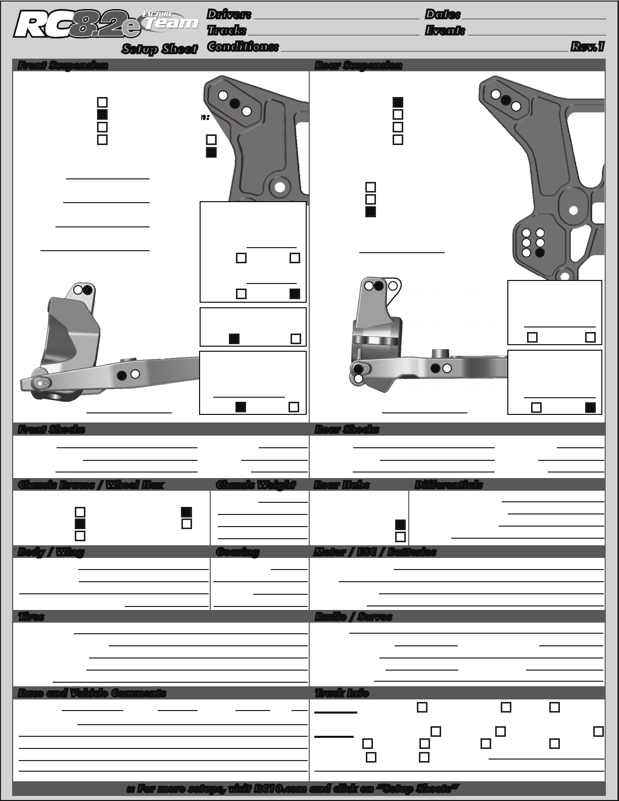
Driver: Date:
RC8.2e FT Standard Setup
Track: Event:
Setup Sheet
Front Suspension
Anti Roll Bar:
2.2mm Green
2.3mm White
Steering System:
2.4mm Blue
2.5mm Yellow
Swing Rack
Bellcrank Rack
Bumpsteer
Washers:
Camber:
Caster:
Toe:
0
-1
16
0
B A
O I
Ride Height: Ride Height:
Conditions: Rev.1
Rear Suspension
Anti Roll Bar:
3
2
2
1
Upper Hinge
Pin Bushing
Front #
1 dot
Up Down
Rear #
3 dot
Up Down
B-Plate Type
Low Original
Kickup Bushing
A-Plate
2 dot
#
Up Down
2.5mm Green
2.6mm White
2.7mm Blue
2.8mm Yellow
Wheelbase:
Long
Medium
Short
Camber:
B A C
Hub:
Upper
Lower
-1
3
2
2
1
36
25
14
1
Toe Bushing
D-Plate
#
1 dot
In Out
Squat Bushing
C-Plate
O
I
29mm28mm
2 dot
#
Up Down
Front Shocks Rear Shocks
Spring: Shock Cap:
Shock Fluid: Length:
Piston: Rebound:
Chassis Braces / Wheel Hex
Chassis Braces: Wheel Hex:
Silver 4.3
30 weight
1.2 1.2
Chassis Weight Rear Hubs
Weight:
Alum.
106mm 122mm
None None
Spring: Shock Cap:
Shock Fluid: Length:
Piston: Rebound:
Rear Hubs:
Pivot Standard
Molded Narrow
Aluminum
Body / Wing
Body Type:
Wing Type:
JConcepts
JConcepts
Gearing
Spur Gear:
46T - Plastic
Pinion:
Gap to Tower (MM):
24mm
Tires
Tire (F/R): /
Compound (F/R): /
Inserts (F/R): /
Wheel (F/R): /
83mm 83mm
Notes:
Race and Vehicle Comments
Qualify: Main: Finish: TQ:
Standard
CNC FT Alum.
Motor / ESC / Batteries
Motor & Wind:
ESC:
ESC Setting:
Batteries:
Radio / Servos
Radio:
Steering Servo: Steering Expo:
Brake Expo:
Initial Brake: Drag Brake:
Dual Rate:
Track Info
Traction: High Medium Low
Comments:
Surface: Smooth Bumpy Blue Groove
Soft Dirt Grass Clay Wet
Astroturf Dusty Other:
30 weight
Differentials
Front Diff Fluid:
Center Diff Fluid:
Rear Diff Fluid:
Notes:
Alum.Silver 3.55
5,000
5,000
5,000
:: For more setups, visit RC10.com and click on “Setup Sheets”
Page 48
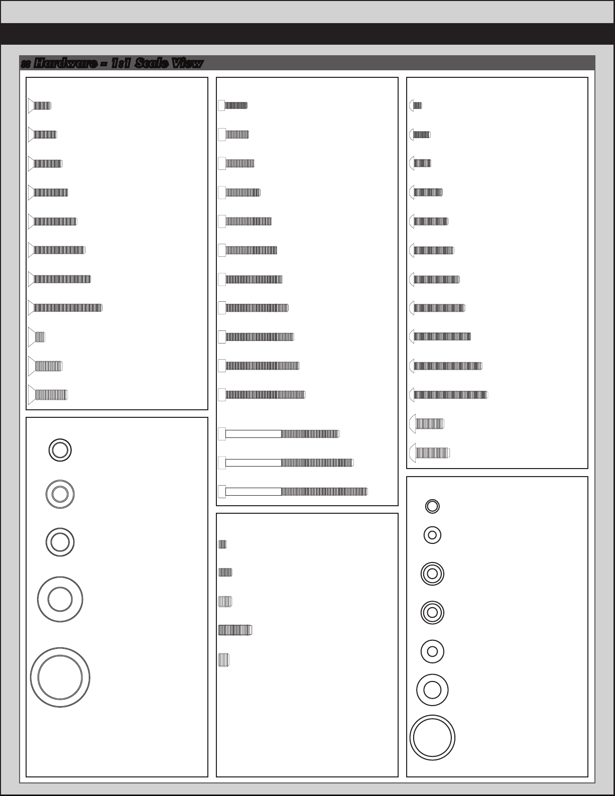
:: Hardware - 1:1 Scale View
48
3x8mm (25201)
3x10mm (25202)
3x12mm (25203)
3x14mm (89208)
3x18mm (89209)
3x20mm (89210)
3x22mm (89455)
3x26mm (89211)
4x6mm (89213)
4x12mm (89214)
Cap Head (shcs)Flat Head (fhcs)
2.5x8mm (89222)
3x8mm (89223)
3x10mm (25620)
3x12mm (89454)
3x16mm (89224)
3x18mm (25191)
3x20mm (25192)
3x22mm (89474)
3x24mm (89225)
3x26mm (89226)
Button Head (bhcs)
2.5x3mm (89201)
2.5x6mm (31520)
3x6mm (31531)
3x10mm (25211)
3x12mm (89202)
3x14mm (25187)
3x16mm (89203)
3x18mm (2308)
3x20mm (25188)
3x24mm (89204)
Ball Bearings
4x14mm (89217)
steering bearing
(89161)
5x10mm (25237)
6x10mm (31404)
8x16mm (25236)
15x21mm (89162)
Set Screws
3x28mm (89227)
3x40mm (89228)
3x45mm (89279)
3x50mm (89452)
3x3mm (25225)
3x5mm (89219)
4x5mm (25226)
4x12mm (89220)
5x4mm (89221)
3x26mm (89205)
4x10mm (89206)
4x12mm (89207)
Shims and Washers
3mm lock washer (89231)
2.5mm washer (89278)
blue countersunk washer
(89229)
silver cone washer (89230)
3x8mm thin washer
(89218)
diff washer (89120)
diff shim (89117)
Page 49

Driver: Date:
Track: Event:
Setup Sheet
Front Suspension
Anti Roll Bar:
2.2mm Green
2.3mm White
Steering System:
2.4mm Blue
2.5mm Yellow
Swing Rack
Bellcrank Rack
Bumpsteer
Washers:
Camber:
Caster:
Toe:
B A
O I
Ride Height: Ride Height:
Conditions: Rev.1
Rear Suspension
Anti Roll Bar:
3
2
1
Upper Hinge
Pin Bushing
Front #
Up Down
Rear #
Up Down
B-Plate Type
Low Original
Kickup Bushing
A-Plate
#
Up Down
2.5mm Green
2.6mm White
2.7mm Blue
2.8mm Yellow
Wheelbase:
Long
Medium
Short
Camber:
B A C
Hub:
Upper
Lower
O
3
2
1
36
25
14
Toe Bushing
D-Plate
#
In Out
Squat Bushing
C-Plate
I
#
Up Down
Front Shocks Rear Shocks
Spring: Shock Cap:
Shock Fluid: Length:
Piston: Rebound:
Chassis Braces / Wheel Hex
Chassis Braces: Wheel Hex:
Chassis Weight Rear Hubs
Weight:
Spring: Shock Cap:
Shock Fluid: Length:
Piston: Rebound:
Rear Hubs:
Pivot Standard
Molded Narrow
Aluminum
Body / Wing
Body Type:
Gearing
Spur Gear:
Wing Type:
Pinion:
Gap to Tower (MM):
Tires
Tire (F/R): /
Compound (F/R): /
Inserts (F/R): /
Wheel (F/R): /
Notes:
Race and Vehicle Comments
Qualify: Main: Finish: TQ:
Standard
CNC FT Alum.
Motor / ESC / Batteries
Motor & Wind:
ESC:
ESC Setting:
Batteries:
Radio / Servos
Radio:
Steering Servo: Steering Expo:
Brake Expo:
Initial Brake: Drag Brake:
Dual Rate:
Track Info
Traction: High Medium Low
Comments:
Surface: Smooth Bumpy Blue Groove
Soft Dirt Grass Clay Wet
Astroturf Dusty Other:
Differentials
Front Diff Fluid:
Center Diff Fluid:
Rear Diff Fluid:
Notes:
:: For more setups, visit RC10.com and click on “Setup Sheets”
Page 50

current products, new releases, setup help, tips, and racing info!
Check out the following web sites for all of our kits,
www.TeamAssociated.com. - www.RC10.com
call: (949) 544-7500 - fax: (949) 544-7501
http://twitter/Team_Associated
http://bit.ly/AEonFacebook
http://www.TeamAssociated.com
Lake Forest, CA 92630 USA
26021 Commercentre Dr.
http://www.RC10.com
Associated Electrics, Inc.
 Loading...