

Page 1
3/13
Page 2
2
:: Introduction
Thank you for purchasing this Team Associated product. This assembly manual contains instructions and tips for building and
maintaining your new RC10 T4.2. Please take a moment to read through this manual to help familiarize yourself with these steps.
We are continually changing and improving our designs; therefore, actual parts may appear slightly different than in the
illustrations. New parts will be noted on supplementary sheets located in the appropriate parts bags. Check each bag for these
sheets before you start to build.
:: KIT Features
Features in the T4.2 Factory Team:
• Factory Team 12mm “Big Bore” hard anodized, threaded aluminum shocks with TiN “Gold” 3mm shock shafts
• VTS slipper (variable torque, multi-plate slipper with 3 drive surfaces) and high-resolution spring
• Factory Team blue aluminum steering bellcrank set
• Factory Team 12mm blue aluminum front and rear clamping hexes with hex drive wheels
• “Gull-wing” front suspension arms and updated front and rear shock towers optimized for12mm big bore shocks
• Factory Team 7075-T6 blue aluminum 0° rear hubs with oversized outer bearing
• Pro-Line Bulldog body
• CVA joints with pin retainer clips
• Ball differential with light-weight outdrives
• Factory Team carbon fiber battery strap and blue aluminum thumb screws
• Complete set of precision ball bearings
• Factory Team blue titanium turnbuckles, blue aluminum hinge pin brace, milled motor plate, servo mounts, rear ballast weight
and much more!
:: Additional
Your new T4.2 FT kit comes unassembled
and requires the following items for completion
(refer to catalog section for suggestions):
• R/C two channel surface frequency radio system
• AA-size batteries for transmitter
(#302 alkaline, #303 rechargealble)
• Electronic Speed Control, ESC (#29140, #29143)
• Steering servo (#29166, #29167) • R/C electric motor
• Pinion gear, size determined by type/wind of motor
• Battery charger (a peak detection charger, or LiPo compatible charger)
• 6 cell NiMH battery pack (#700) or a 2 cell LiPo battery pack (#714)
• Calipers or a precision ruler • Needle nose pliers
• Lexan specific spray paint
• Reamer / hole punch
• Cyanacrylate glue (#1597)
• Thread locking compound (#1596)
• Tires and Inserts, Fronts and Rears
Tools included:
• Allen wrenches #6950 (.050”, 1/16”, 3/32”, 5/64”)
• Molded tools #6956
• Camber gauge #1719
:: Other Helpful Items
• Silicone Shock Fluid (Refer to catalog for complete listings)
• Body Scissors (AE Part # 1737) • Reamer / Hole Punch • Wire Cutters • Hobby Knife
• FT Hex Wrenches (AE Part # 1655) • Needle Nose Pliers • Multi Tool (AE Part #7494)
• Soldering Iron • Calipers or a Precision Ruler • Green Slime shock lube (AE Part # 1105)
Associated Electrics, Inc.
26021 Commercentre Dr.
Lake Forest, CA 92630
http://www.TeamAssociated.com · http://www.RC10.com · http://twitter.com/Team_Associated · http://bit.ly/AEonFacebook
Customer Service
Tel: 949.544.7500
Fax: 949.544.7501
Page 3
:: Table of Contents
1................... Cover
2................... Introduction
3................... Table of Contents
3
14 - 16........ Electronics Build
(Bag H-HH)
16 - 17........ Wheels, Tires and Body Install
(Bag I)
4................... Steering Build
(Bag A-AA)
4 - 5............. Front End, Outer Build
(Bag B-BB)
5 - 6............. Front End, Inner Build
(Bag C)
6 - 9............. Transmission Build
(Bag D-DD)
9 - 11........... Rear End Build
(Bag E-EE)
11 - 12........ CVA and Turnbuckle Build
(Bag F-FF)
12 - 14........ Shocks Build
(Bag G-GG)
17................. Servo Chart
18 - 19....... Tuning Tips
20 - 29....... Catalog
30................ Notes
31................ Setup Sheet “Kit Setup”
32................ 1:1 Hardware “Fold Out”
33................ Setup Sheet “Blank”
34................ Back Cover
:: Notes
There is a 1:1 hardware foldout page in the back
of the manual. To check the size of a part, line
!
This symbols indicates a
special note or instruction
in the manual.
Associated Electrics, Inc.
26021 Commercentre Dr.
Lake Forest, CA 92630
http://www.TeamAssociated.com · http://www.RC10.com · http://twitter.com/Team_Associated · http://bit.ly/AEonFacebook
up your hardare with the correct drawing until
you find the exact size. Each part in the foldout
has a number assigned to it for ordering
replacement parts.
Customer Service
Tel: 949.544.7500
Fax: 949.544.7501
Page 4
4
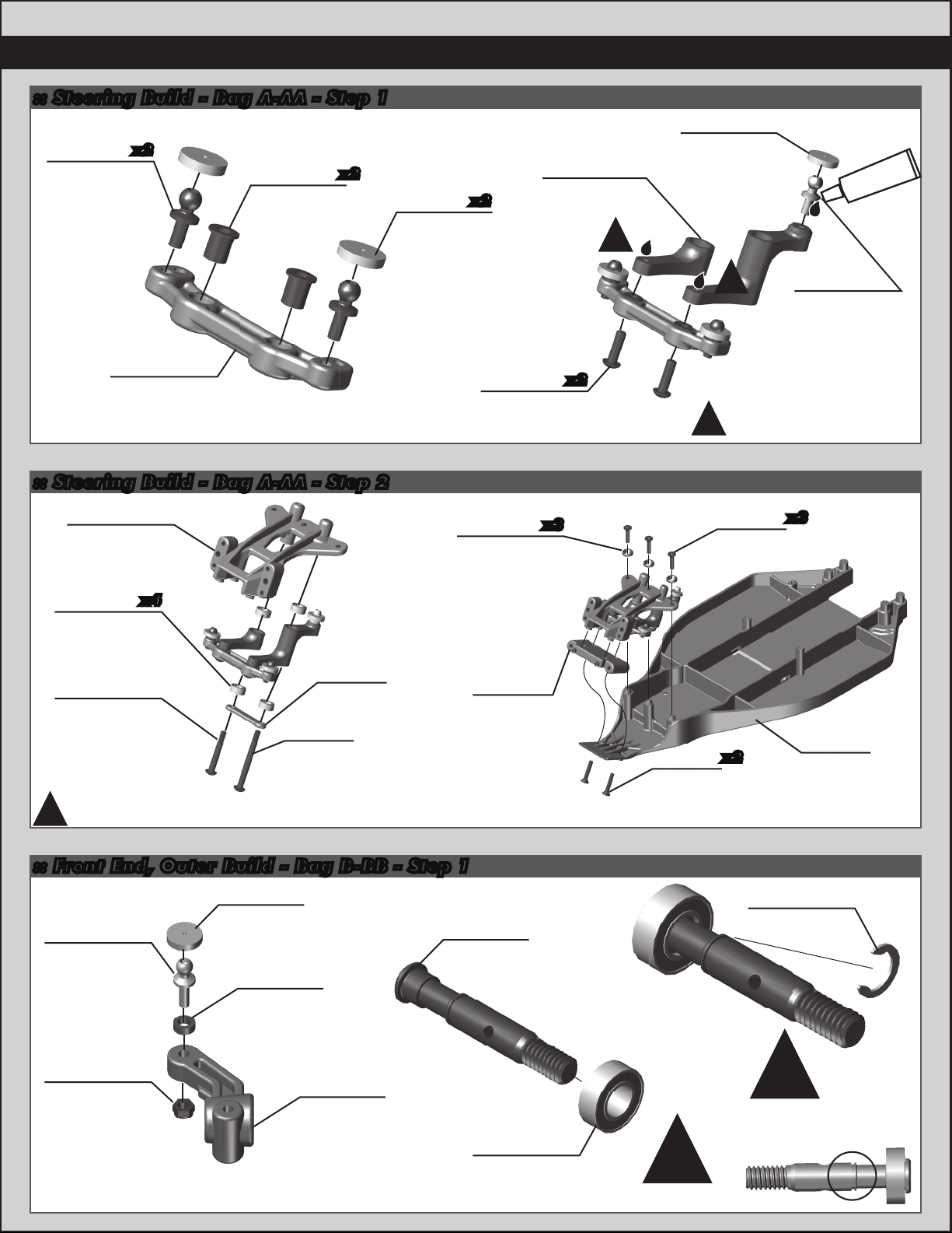
:: Steering Build - Bag A-AA - Step 1
3981
Ballstud, .20
black, short
x2
9647
Block carrier
bushing
x2
6272
Dust cover
foam
x2
9679
FT Aluminum
Bellcrank Set
!
6272
Dust cover
foam
#1596
thread lock
9659
Steering
rack
:: Steering Build - Bag A-AA - Step 2
9566
Top plate
3971
Steering rack
bearing
9640
Steering
bolt
(right)
Do not overtighten steering bolts. Make sure
!
there is free movement in the steering rack.
x4
9659
Steering
brace
9640
Steering
bolt
(left)
6917
4-40x3/8
bhcs
89229
Blue
countersunk
washer
9563
Front
bulkhead
x3
x2
!
4-40x1/2
6915
4-40x5/8
fhcs
!
Be careful to not get
thread lock on steering
rack bushings!
6922
fhcs
x2
6276
Ballstud, .20
silver, short
x3
7440
T4 chassis
:: Front End, Outer Build - Bag B-BB - Step 1
6272
Dust cover
6277
Ballstud, .30
silver, long
4449
4-40x3/16
aluminum
locknut
foam
31286
FT ballstud
washer,
aluminum
(2mm)
9880
Steering
block, hex
7854
T4 front
axle, hex
3977
3/16x3/8
bearing
!
Build 2 (1 left, 1 right) Build 2!
9882
C-clip, 3/16
!
Install the C Clip
into the groove
shown below.
Page 5
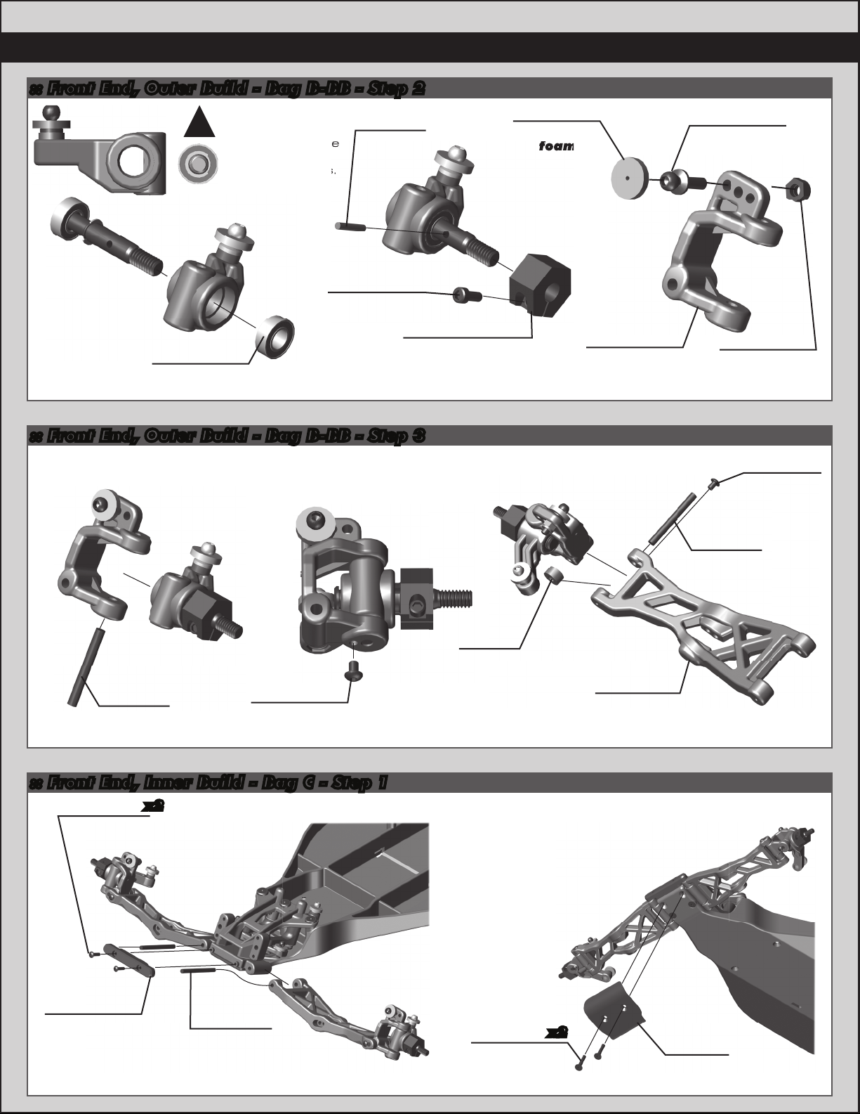
:: Front End, Outer Build - Bag B-BB - Step 2
foam
!
3977
3/16x3/8
bearing
Align the C-clip on
the front axles
with the D-shape
inside the
steering blocks.
7369
1/16
universal
roll pin
9898
2-56x3/16
shcs
12mm aluminum
clamping wheel
:: Front End, Outer Build - Bag B-BB - Step 3
9892
hex, rear
6272
Dust cover
foam
(1 left, 1 right)
7922
Caster block,
30°
5
3983
Ballstud, .30
black, short
4449
4-40x3/16
aluminum
locknut
9622
Hinge pin,
front outer
9645
2-56x1/8
bhcs
:: Front End, Inner Build - Bag C - Step 1
4334
2-56x5/16
bhcs
x2
9645
2-56x1/8
bhcs
9622
Hinge pin,
front outer
7922
Spacer
91201
SC10B
a-arms,
front
9665
FT front
hinge pin
brace
9621
Hinge pin,
front inner
6915
4-40x5/8
fhcs
x2
9562
Front
bumper
Page 6
6
Ball diff
rings
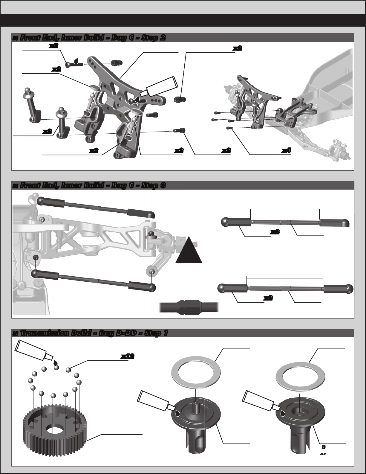
:: Front End, Inner Build - Bag C - Step 2
7413
4-40x3/4
bhcs
6272
Dust cover
foam
x2
x2
91202
SC10B
front shock
tower
#1596
thread lock
1780
FT aluminum
shock bushings,
standard
x2
7439
x2
Front body
mount
31286
FT ballstud washer,
aluminum (2mm)
x2
6277
Ballstud .30
silver, long
:: Front End, Inner Build - Bag C - Step 3
x2
6925
4-40x1/2
shcs
!
Orient the notch
to the left
throughout the
car. It indicates
which end has the
left hand threads!
x2
6924
x4
4-40x3/8
shcs
Front Camber Turnbuckle
1.92” (48.75mm)
7230
ball cup
(large)
x2
turnbuckle
Steering Turnbuckle
2.07” (52.75mm)
7230
ball cup
(large)
x2
turnbuckle
1408
2.65”
1417
2.80”
:: Transmission Build - Bag D-DD - Step 1
#6591
diff lube
x12
7664
Diff gear
52T
6581
3/32 carbide
diff balls
#6591
diff lube
7666
Drive
rings
9852
Ball diff
outdrives
#6591
diff lube
7666
Drive
rings
9852
Ball diff
outdrives
Page 7
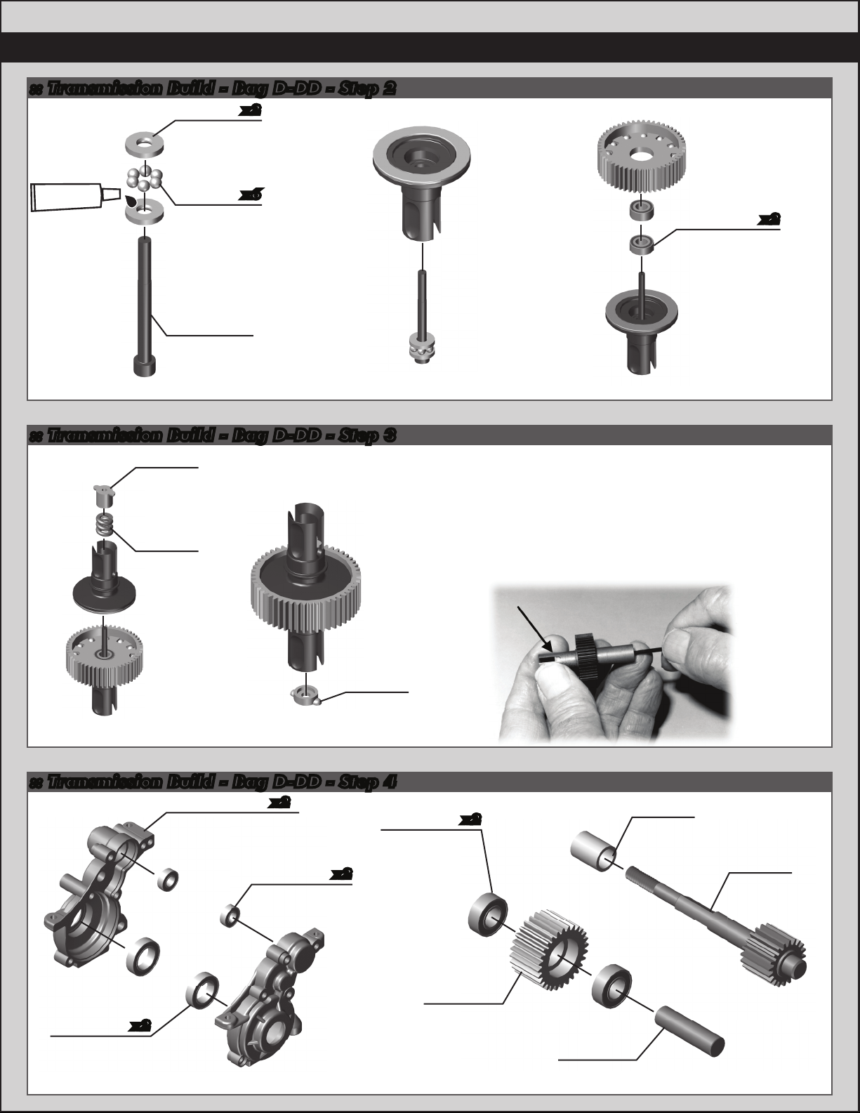
:: Transmission Build - Bag D-DD - Step 2
6573
Diff thrust
washer
x2
7
#6588
black grease
6574
x6
5/64 diff
thrust
balls
6573
Diff thrust
bolt
:: Transmission Build - Bag D-DD - Step 3
6575
Locking
t-nut
6582
Diff
thrust
spring
6589
x2
5/32 x 5/16,
unflanged
bearing
As you tighten the diff bolt, you will notice the T-nut ears moving
closer to the bottom of the outdrive slot. This compresses the
spring behind the T-nut. The spring should be completely com-
pressed at the same time the T-nut reaches the end of the slot.
Caution! Pay close attention to the feeling when the spring is
completely compressed. Do not overtighten the bolt. When you
feel the spring completely compressed, loosen the diff bolt 1/8”
of a turn. Your diff should now operate smoothly with resistance
as the outdrives move in opposite directions. After you have
driven the car once, re-check the diff setting.
6575
Diff
cover
:: Transmission Build - Bag D-DD - Step 4
x2
3977
x2
Ball bearing
3/16x3/8
Ball bearing
9832
x2
Ball bearing
10x16mm
9826
Transmission case
(1 left, 1 right)
3977
3/16x3/8
9360
Idler gear
x2
9602
Top shaft
spacer
9601
Top shaft
9361
Idler gear
shaft
Page 8
8
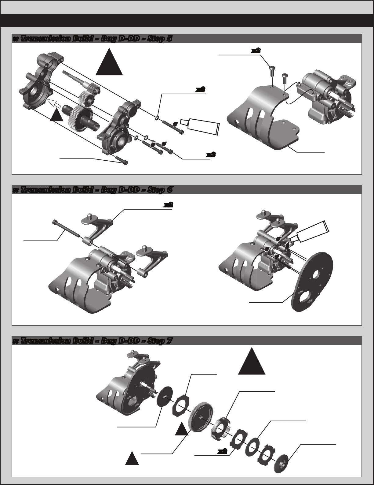
:: Transmission Build - Bag D-DD - Step 5
Install the Diff with
the head of the
Diff Thrust Bolt
(#6573) facing the
!
right side of the
transmission case!
6919
4-40x5/16
bhcs
x2
.030 ballstud
!
6925
4-40x1/2
shcs
:: Transmission Build - Bag D-DD - Step 6
9587
Wing mounts
(1 left, 1 right)
6913
4-40x1 1/4
shcs
x2
9630
washer
6928
4-40x1
shcs
x3
#1596
thread lock
x3
9819
Motor
guard
#1596
thread lock
:: Transmission Build - Bag D-DD - Step 7
7485
FT V2
slipper hub
9653
84T 48P
!
spur gear
!
9603
Slipper
pad
91177
VTS
slipper
pads
x2
1770
FT milled
motor plate
(blue)
There’s also a 75T
!
91176
VTS slipper
housing
included for stock
VTS slipper
48P Spur Gear
(#9650)
motors use!
91178
plate
91179
VTS slipper
hub, outer
Page 9
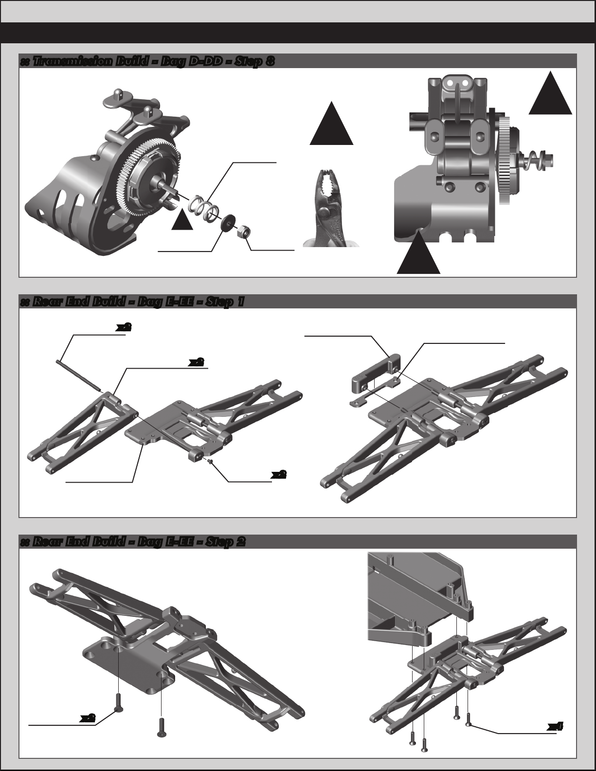
:: Transmission Build - Bag D-DD - Step 8
9739
Slipper
spring
!
!
Compress
spring first.
9
!
Set nut
flush with
top shaft.
7486
V2 slipper
washer
:: Rear End Build - Bag E-EE - Step 1
9621
Hinge pin,
rear inner
9818
Rear chassis
plate
x2
7448
Rear T4 a-arms
(1 left, 1 right)
x2
2-56x1/8
locknut
9645
bhcs
6629
5-40
x2
7487
Rear arm
mount
(3.0 degree)
See page 18 for gear
!
mesh, and slipper clutch
setting instructions!
7487
Anti-squat shim
(2 degrees)
:: Rear End Build - Bag E-EE - Step 2
9269
5-40x1/2
fhcs
x2
9269
5-40x1/2
fhcs
x4
Page 10
10
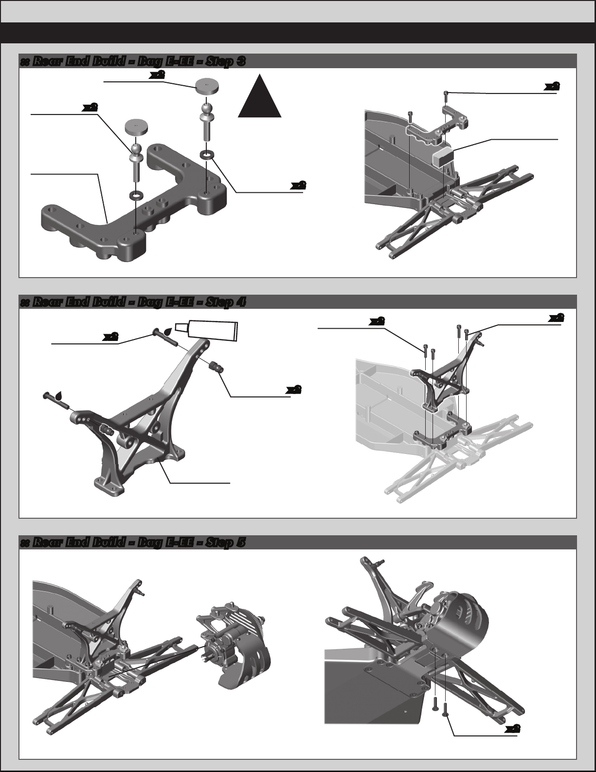
:: Rear End Build - Bag E-EE - Step 3
6272
Dust cover
6277
Ballstud .30
silver, long
9564
Rear chassis
brace
x2
foam
:: Rear End Build - Bag E-EE - Step 4
7413
4-40x3/4
bhcs
x2
x2
Use inside hole in
chassis brace!
FT ballstud
#1596
thread lock
!
31286
washer,
aluminum
(1mm)
x2
9644
5-40x9/16
shcs
x2
9643
5-40x7/16
shcs
7488
Rear ballast
weight
9643
5-40x7/16
shcs
x2
x2
FT aluminum
shock bushing,
9824
T4 rear shock
tower
:: Rear End Build - Bag E-EE - Step 5
1781
short
x2
6922
4-40x1/2
fhcs
x2
Page 11
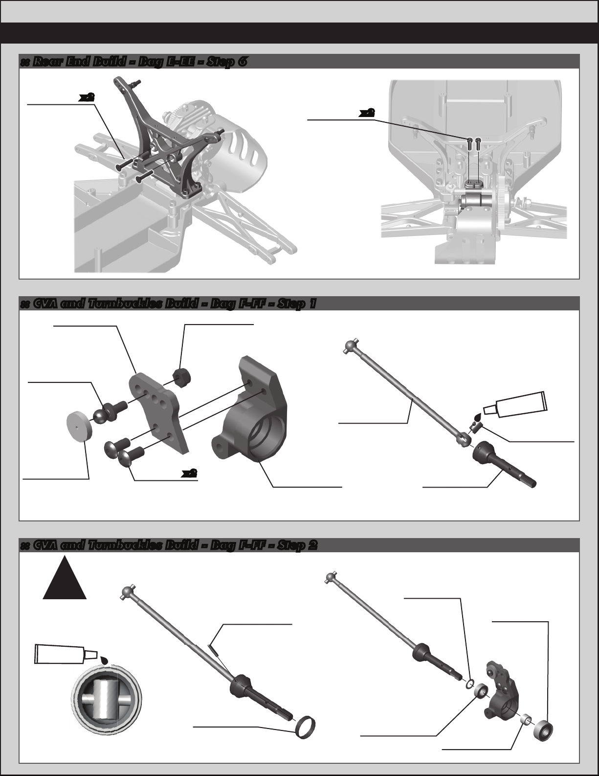
:: Rear End Build - Bag E-EE - Step 6
11
6915
4-40x5/8
fhcs
x2
:: CVA and Turnbuckles Build - Bag F-FF - Step 1
9917
Aluminum
hub A,
carbon
3981
Ballstud, .20
black, short
4449
4-40x3/16
aluminum
locknut
Left Side
6924
4-40x3/8
shcs
FT CVA bone
x2
9596
(T4)
#6588
black grease
7381
CVA coupler
6272
Dust cover
foam
Build x2 (right and left side)
6288
4-40x1/4
bhcs
x2
9864
FT aluminum
hub ( 0˚)
:: CVA and Turnbuckles Build - Bag F-FF - Step 2
!
Align the gap in
the pin retainer
to be opposite of
the CVA pin.
#1597
ca glue
1 drop!
CA glue not
included
Build x2
7996
CVA pin
retainer
7381
CVA cross
pin
3/16 axle
3977
3/16x3/8
bearing
CVA axle
7368
shim
9755
rear
7935
.187x.196
bearing
7933
Crush tube
Page 12

12
Build x2
(right and left side)
Orient the notch
which end has the
left hand threads!
:: CVA and Turnbuckles Build - Bag F-FF - Step 3
7369
1/16
roll pins
9892
12mm aluminum
clamping wheel
hex, rear
9898
2-56x3/16
shcs
Build x2 (right and left side)
:: CVA and Turnbuckles Build - Bag F-FF - Step 4
9645
2-56x1/8
bhcs
(right and left side)
9622
Hinge pin,
rear outer
Build x2
31286
FT ballstud
washer,
aluminum
(1mm)
9630
.030 ballstud
washer
:: Shocks Build - Bag G-GG - Step 1
91308
12mm shock
piston
(1.6 front)
(1.7 rear)
91306
27.5x3 TiN
shock shaft
(front)
91307
35x3 TiN
shock shaft
(rear)
numbers on the pistons to
make them easily visible!
6299
1/8 E-clip
Racers Tip:
Use a marker over the
Orient the notch
to the left
throughout the
car. It indicates
which end has the
left hand threads!
!
!
Steering Turnbuckle
2.10” (53.5mm)
7230
ball cup
(large)
6299
1/8 E-clip
x2
Build x2 (right and left side)
1417
2.80”
turnbuckle
4187
Nylon spacer,
(.030)
Front:
4 spacers
Rear:
2 spacers
Page 13

:: Shocks Build - Bag G-GG - Step 2
91309
Shock
spacer
91300
12x27.5mm
shock bodies
(front)
91302
12x36mm
shock bodies
(rear)
5407
x2
O-ring
91309
x2
Shock hat
bushing
91309
12mm shock
cap o-ring
Lightly rub shock oil on the
o-ring before installation!
31327
VCS3 shock
bottom cap
o-ring
#1105
green slime
31327
VCS3 shock
bottom cap
:: Shocks Build - Bag G-GG - Step 3
!
Racers Tip:
!
Racers Tip:
Coating the o-rings
!
with green slime
(#1105) helps seal
& reduce o-ring
swell! Green slime
not included in kit!
!
#1105
green slime
13
1777
Shock
eyelet
1777
FT shock
pivot ball
Step 2-3
Shock oil
#5429
Front Shock: 35 wt
Rear Shock: 35 wt
Shock oil
#5429
91303
12mm
shock cap
:: Shocks Build - Bag G-GG - Step 4
91304
12mm
threaded
collar
o-ring
x4
Racers Tip:
Use your finger to rub
shock oil on the o-ring for
smoother adjustment!
x4
!
Shock Bleeding Steps:
1. Before assembly, get each bleed
screw and thread it 1-2 turns into the
shock cap. This will make installation
easier when you are bleeding your
shocks.
2. Pull shock shaft down.
3. Fill shock body 3/4 full with silicone
shock fluid.
4. Slowly move the shock shaft up and
down to remove air from under the
piston.
5. Wait for bubbles to come to surface.
6. Fill shock body to top with silicone
shock fluid.
7. Place a drop of oil in the cap and on
cap threads.
8. Install cap (without bleed screw) and
tighten completely.
9. Slowly compress shaft all the way to
bleed excess silicone shock fluid out
the hole in the cap (use rag aroundshock to catch excess fluid).
10. Install M2x4mm button head screw
until snug while shaft is fully compressed.
Front:
8mm
Rear:
8.5mm
91309
Shock cap
o-ring
31510
M2x4mm
bhcs
Step 9-10Step 8Step 6-7Step 4-5
x4
x4
91304
12mm
threaded
collar
x4
91329
12mm front
spring, Gray
(3.45lb)
91336
12mm rear
spring, Green
(2.00lb)
91310
12mm shock
spring cup
(9mm offset)
Build x2 front and x2 rear shocks
Page 14

14
(approximately one notch)
:: Shocks Build - Bag G-GG - Step 5
x2
!
Use outside
hole in
front arm!
6927
4-40x3/4
shcs
6472
Shock
mount nut
x2
!
Use inside
hole in
rear arm!
6472
Shock
mount nut
x2
:: Electronics Build - Bag H-HH - Step 1
ring
Servo not
included!
!
3981
Ballstud, .20
black, short
Servo screw
not included!
9180
Servo
horn
6272
Dust cover
foam
89007
Servo horn
Offset the servo horn by
5-10 degrees
!
6917
4-40x3/8
bhcs
See page 17 for correct
servo spacing on the
(approximately one notch)
x2
servo chart!
7337
Gold
washer
4-40x1/2
1779
FT Servo
mount
7336
Servo
spacers
x4
6925
shcs
x2
x2
x2
:: Electronics Build - Bag H-HH - Step 2
Servo link
!
Leave a
2mm gap!
9170
6292
4-40x3/8
x2
fhcs
Page 15

:: Electronics Build - Bag H-HH - Step 3
15
Motor not included!
:: Electronics Build - Bag H-HH - Step 4
Pinion / Setscrew
not included!
6936
Washer #4
aluminum
!
x2
See page 18 for
gear mesh setting
instructions!
31532
M3x8mm
bhcs
x2
:: Electronics Build - Bag H-HH - Step 5
7461
Gear cover
(clear)
3862
5-40x1/8
set screw
6338
Antenna
tube & cap
7461
Gear cover
button
6285
4-40x1/4
shcs
Receiver / Servo tape
not included!
x2
ESC/ Servo tape
not included!
Page 16

16
:: Electronics Build - Bag H-HH - Step 6
1787
4-40x1/2
set screw
x2x2
9238
Foam
battery
spacer
1787
FT battery
strap thumb
screws
x4
x2
7452
Battery strap,
carbon
:: Wheels / Tires and Body - Bag I - Step 1
7852
Truck wheel
hex, white
Tires / Inserts
not included!
x4
Carefully apply ca
glue to the tire bead.
Do one side at a
time, allow it to dry
before gluing the
other side!
!
#1597
ca glue
Battery
not included!
6953
8-32
LP steel
locknut
x2
Page 17

:: Wheels / Tires and Body - Bag I - Step 2
Front
17
6952
x2
8-32
locknut,
steel
:: Wheels / Tires and Body - Bag I - Step 3
9587
x2
Wing
shims
Front
Painting Tips:
Body :
Your vehicle comes with a clear polycarbonate body.
You will need to prep the body before you can paint
it. Wash the inside thoroughly with warm water and
liquid detergent. Dry the body using a clean, soft,
lint-free cloth. Use the supplied window masks to
cover the windows from the INSIDE of the body
(RC cars get painted from the inside).
Using high quality masking tape, apply tape to the
inside of the body to create a design. Spray (either
rattle can or airbrush) the paint to the inside of the
body (prefferably dark colors first, lighter colors last).
6332
Body
clips
:: Servo Chart
x4
NOTE: use ONLY paint that is recommended for use
with (polycarbonate) plastics. If you don’t, you can
destroy the plastic body!!!!).
After painting, cut the body along the trim lines. Make
sure to drill or use a body reamer to make the holes
for the body mounts and antenna!
Steering Servo Chart
Associated
Airtronics
Airtronics
Hitec
Hitec
Futaba
Futaba
KO
* Not all servo’s are listed
* Make sure servo linkage clears the servo through full travel in both directions.
Use #7336 servo spacers to adjust the servos position
(to make the steering link as straight as possible)
XP-1015, XP-1313
94102
94257, 94258, 94357,
94358, 94452, 94453, 94755
HS-5625MG, HS-5645MG, HS645MG
HS-965, HS-985MG,
HS-5965, HS-5985MG
Z4750, Z2750
JR
Z250, Z550
JR
S9204, S9250, S9450
S9404
PS-401, PS-2001, PS-2004, PS -2015, PS-2173,
PS-2174, PS-2123, PS-2143, PS -2144
# 9180
servo arm
F
A
A
H
H
J
J
F
F
J
Page 18

18
:: Tuning Tips
Tips for Beginners:
Before making any changes to the standard setup, make sure you can get around the track without crashing. Changes
to your vehicle will not be beneficial if you can’t stay on the track. Your goal is consistent laps.
Once you can get around the track consistently, start tuning your vehicle. Make only ONE adjustment at a time, testing
it before making another change. If the result of your adjustment is a faster lap, mark the change on the included setup
sheet (make adddtional copies of the sheet before writing on it). If your adjustment results in a slower lap, revert back to
the previous setup and try another change.
When you are satisfied with your vehicle, fill in the setup sheet thoroughly and file it away. Use this as a guide for future
track days or conditions.
Peridicaly check all moving suspension parts. Suspension components must be kept clean and move freely without
binding to prevent poor and/or inconsistent handling.
Motor Gearing:
Proper motor gearing will result in maximum performance and run time while reducing the chance of overheating and
premature motor failure. The gear ratio chart lists recommended starting gear ratios for the most widely used motor
types. Gear ratios will vary depending upon motor brand, wind, and electronic speed control. Consult your motor and
electronic speed control manufacturers for more information. Team Associated is not responsible for motor damage
due to improper gearing. * These gearings are for use with advanced timing speed control settings!
T4.2 Gear Ratio Chart (Internal Gear Ratio 2.60:1)
Motor Pinion Spur FDR
27T Reedy Stock
19T Reedy Super Stock
17.5 Reedy Sonic Brushless *
17.5 Reedy Sonic Brushless
13.5 Reedy Sonic Brushless *
13.5 Reedy Sonic Brushless
10.5 Reedy Sonic Brushless
9.5 Reedy Sonic Brushless
8.5 Reedy Sonic Brushless
7.5 Reedy Sonic Brushless
6.5 Reedy Sonic Brushless
3300kV Brushless
3900kV Brushless
4900kV Brushless
6100kV Brushless
20
19
21
28
19
25
21
20
20
19
19
19
19
18
17
84
84
84
75
84
78
84
84
84
84
84
84
84
84
84
10.92:1
11.49:1
10.40:1
7.501
11.49:1
8 .111
10.40:1
10.921
10.921
11.49:1
11.49:1
11.49:1
11.49:1
12.13:1
12.85:1
Set The Gear Mesh:
You should be able to rock the spur gear back and forth in the teeth of the pinion gear without making the pinion gear
move. If the spur gear mesh is tight, then loosen the #31532 screws and move the motor away, then try again.
A gear mesh that is too tight or too loose will reduce power and damage the gear teeth.
Motor Maintenance:
Brushed motors require frequent maintenance to keep performance levels at their maximum. Between runs and after
letting the motor cool completely, inspect the brushes to ensure that they are moving freely in their holders.
Remove the springs and slide the brushes in and out of their holders checking for any resistance or rough spots.
If found, remove the brush and carefully wipe it clean. Removing buildup will allow the brush to slide freely and create
maximum contact with the commutator resulting in maximum power output.
After every 3-5 runs, remove the brushes from their holders and inspect the tips for wear or burning. If there is
noticeable wear (less than 75% of the brush remaining), it is best to cut the commutator and replace the brushes with
a new pair. If the tips become a burned blue color, the lubricant in the brush has been burned away and new brushes
should be installed.
Occasionally, the motor should be cleaned with a soft brush to prevent dirt build up around the brush hood area and ball
bearings. At this time, it is a good idea to add one drop of bushing / bearing oil to each bushing or ball bearing.
If using a brushless motor, please refer to the motor manufacturer’s guidelines for proper maintenance.
Slipper Clutch:
The assembly instructions give you a base setting for your clutch. Turn the nut on the shaft so that the end of the top
shaft is even with the outside of the nut. At the track, tighten or loosen the nut in 1/8 turn increments until you hear
a faint slipping sound for 1-2 feet on takeoffs. Another popular way to set the clutch is to hold both rear tires firmly in
place and apply short bursts of throttle. If the clutch is properly set, the front tires should lift slightly up of f the surface.
Page 19

:: Tuning Tips (cont.)
Front Camber Links:
Changing the length of the camber link is considered a bigger step than
adjusting the ball end height on the tower. Shortening the camber link
(or lowering the ball end) will give the front end less roll and quicken steering
response. Lengthening the camber link (or raising the ball end) will give the
front more roll and slower steering response. Longer camber links are
typically used on high grip tracks and shorter links tend to work better on
medium-grip loose tracks.
*Raise or lower the
ball end by adding
!
or subtracting
washers here
Front Camber:
Camber describes the angle at which the tire and wheel rides when
looked at from the front. Negative camber means that the tire leans
inward at the top. A good starting camber setting is -1°. Use the
included #1719 camber gauge to set your camber. Positive camber,
where the top of the tire is leaning out, is not recommended.
*Testing camber
with camber gauge
!
Caster:
Caster describes the angle of the kingpin as it leans toward the rear of the vehicle. Positive caster means the kingpin
leans rearward at the top. The supplied 30° caster blocks (#7922) are recommended in most cases.
For less corner entry steering and more exit steering, try the optional 25° blocks (#7919).
Rear Camber Link:
19
Changing the length of the camber link is considered a bigger step than adjusting
the ball end height on the rear chassis brace. Shortening the camber link
(or lowering the ball end) will give the rear end less roll and the car will tend to
accelerate or “square up” better. Lengthening the camber link (or raising the ball
end) will give the rear more roll and more cornering grip. Longer camber links are
typically used on high grip tracks, while shorter links tend to work better on
medium grip loose tracks. The kit setting is the best compromise of cornering grip
and acceleration.
*Raise or lower
!
the ball end by
adding or
subtracting
washers here
Rear Camber:
Camber describes the angle at which the tire and wheel rides when looked at from the back. Negative camber means
that the tire leans inward at the top. A good starting camber setting is -1°. Use the included #1719 camber gauge to
set your camber. Adding a small amount of positive camber, where the top of the tire is leaning out, will tend to improve
straight-line acceleration on loose tracks.
Ride Height:
!
Ride height is the distance from the ground to the bottom of the
chassis. The standard front ride height setting is with the inner
and outer hinge pins of the front arms level on the same imaginary
horizontal line, or 30mm as measured from the bottom of the
chassis directly behind the front bumper.
The rear ride height setting you should use most often is with the
outdrive, driveshaft, and axles all on the same imaginary horizontal
line (reffered to as “bones level”) or 28mm.
Check the ride height by lifting up the entire car about 8-12 inches
off the bench and drop it. After the suspension “settles” into place,
measure ride height (Ride Height Gauge #1449). Raise or lower
the shock collars as necessary.
*Front arms
inner and outer
hinge pins should
be in a imaginary
horizontal line
when ride height
is set
!
*CVA bones should
be in a straight line
when ride height is
set at “CVA bones
level”
Wheelbase Adjustment:
You have three options for rear hub spacing, Forward, Middle, & Back.
The kit setting provides the most rear traction, and will be used most often.
For improved handling in bumps or rhythm sections, try moving the hubs to the
Middle or Back position. This can also make the car handle better in 180° turns.
*Spacers to the rear
will place hubs for-
ward, shortening
the wheelbase
!
Anti-Roll Bars:
The optional #9635 rear anti-roll bar kit (also called the “swaybar”) allows you to add roll resistance to the rear end with
minimal effect on handling over bumps and jumps. It is an especially helpful tuning item on high-grip tracks
(try the gold bar). The silver and black anti-roll bars are typically used on medium-grip loose tracks.
Page 20

20
:: Shocks
1777
FT Blue Aluminum Shock Pivot Ball with Eyelet
4187
.030 Nylon Washer
5407
Red O-Rings
6299
31327
31510
91300
91302
91303
91304
91306
91307
91308
91309
91310
91315
91317
E-Clip
VCS3 Shock Bottom Cap and O-Ring
M2 x 4mm BHCS
12X27.5mm FT Shock Bodies (front)
12X36mm FT Shock Bodies (rear)
12MM Shock Cap
12MM Threaded Collar and O-Ring
27.5X3mm TiN Shock Shaft (front)
35X3mm TiN Shock Shaft (rear)
12MM Shock Pistons, (1.5, 1.6, 1.7)
12MM Shock Rebuild Kit
12MM Shock Spring Cups (+0mm, +5mm, +9mm)
12MM Shock (T4/SC10 Front)
12MM Shock (T4/SC10 Rear)
31510
91309
91309
91303
91309
91300
91302
31327
31327
5407
5407
6299
91308
6299
91306
91307
4187
91304
91304
91310
1777
1777
4 ea.
12
8
12
2 ea.
6
2
2
2
2
1
1
4 ea.
1
4 ea.
2
2
:: Ball Differential
6573
6574
6575
6581
6582
6589
7664
7666
7677
9852
9853
Diff Thrust Washer & Bolt
Precision Diff Thrust Balls, 5/64”
Locking T-Nut, Diff Thrust Bolt, & Cover
3/32” Carbide Diff Balls
Diff Thrust Spring
Ball Bearing, 5/32 x 5/16” unflanged
Diff Gear 52T
Diff Drive Rings, 2.60:1
B4 / T4 / GT Diff Rebuild Kit
SC10 Ball Diff Outdrives
SC10 Complete Ball Differential
6575
6582
9852
7666
6589
6581
7664
2
6
1
12
1
2
1
2
1
1
1
9853
6589
7666
9852
6573
6574
6573
6575
6575
:: Shock Springs
91325
91326
91327
91328
91329
91330
91331
91332
91333
91334
91335
91336
91337
91338
91339
91340
91341
91342
91343
91344
91345
12MM Front SPRING BRN 2.85
12MM Front SPRING BLK 3.00
12MM Front SPRING GRN 3.15
12MM Front SPRING WHT 3.30
12MM Front SPRING GRY 3.45 - Kit
12MM Front SPRING BLU 3.60
12MM Front SPRING YLW 3.75
12MM Front SPRING RED 3.90
12MM Front SPRING ORN 4.05
12MM Front SPRING PRL 4.20
12MM Rear SPRING BLK 1.90
12MM Rear SPRING GRN 2.00 - Kit
12MM Rear SPRING WHT 2.10
12MM Rear SPRING GRY 2.20
12MM Rear SPRING BLU 2.30
12MM Rear SPRING YLW 2.40
12mm Big Bore Front Soft Spring Kit
12mm Big Bore Front Medium Spring Kit
12mm Big Bore Front Hard Spring Kit
12mm Big Bore Rear Soft Spring Kit
12mm Big Bore Rear Medium Spring Kit
Pr.
Pr.
Pr.
Pr.
Pr.
Pr.
Pr.
Pr.
Pr.
Pr.
Pr.
Pr.
Pr.
Pr.
Pr.
Pr.
1
1
1
1
1
:: Shock Oil
5420
5421
5422
5423
5424
5425
5426
5427
5428
5429
5430
5431
5432
5433
5434
5435
5436
5437
5438
10 Weight Silicone Shock Oil
20 Weight Silicone Shock Oil
30 Weight Silicone Shock Oil
40 Weight Silicone Shock Oil
22.5 Weight Silicone Shock Oil
80 Weight Silicone Shock Oil
27.5 Weight Silicone Shock Oil
15 Weight Silicone Shock Oil
25 Weight Silicone Shock Oil
35 Weight Silicone Shock Oil
45 Weight Silicone Shock Oil
55 Weight Silicone Shock Oil
32.5 Weight Silicone Shock Oil
37.5 Weight Silicone Shock Oil
42.5 Weight Silicone Shock Oil
50 Weight Silicone Shock Oil
60 Weight Silicone Shock Oil
70 Weight Silicone Shock Oil
47.5 Weight Silicone Shock Oil
2oz.
2oz.
2oz.
2oz.
2oz.
2oz.
2oz.
2oz.
2oz.
2oz.
2oz.
2oz.
2oz.
2oz.
2oz.
2oz.
2oz.
2oz.
2oz.
Page 21

:: Slipper Clutch
6285
6629
7461
7485
7486
9603
9649
9650
9651
9652
9653
9739
91175
91176
91177
91178
91179
4-40 x 1/4” SHCS
5-40 Diff Locking Nut
Molded Gear Cover, Clear
FT V2 Slipper Hubs
FT V2 Slipper Spring and Washer
Slipper Pad
72T 48P Spur Gear
75T 48P Spur Gear
81T 48P Spur Gear
78T 48P Spur Gear
84T 48P Spur Gear (Kit)
Slipper Spring
FT VTS Slipper Conversion
VTS Slipper Housing
VTS Slipper Pads
VTS Slipper Plate
FT VTS Slipper Hub, outer
:: Optional Gear Differential
9827
9828
9829
9830
9831
9888
Complete Gear Diff
Diff Gear and Cover Set
Gear Diff Rebuild Kit
Gear Diff Outdrives
Gear Diff O-Ring Set
0.5mm Gear Diff Shim
1
1
1
Pr.
1
2
12
21
6
1
2
1
2
1
7485
1
1
1
1
1
1
1
2
1
1
9830
9653
9830
9831
9828
9603
91177
9828
91177
9831
91176
9739
9888
91178
6629
9829
91179
7486
6285
7461
7461
6285
:: Differential Fluids
5450
5451
5452
5453
5454
5455
5456
5457
5458
5459
Silicone Diff Fluid 1,000CST
Silicone Diff Fluid 2,000CST
Silicone Diff Fluid 3,000CST
Silicone Diff Fluid 5,000CST
Silicone Diff Fluid 7,000CST
Silicone Diff Fluid 10,000CST
Silicone Diff Fluid 20,000CST
Silicone Diff Fluid 30,000CST
Silicone Diff Fluid 60,000CST
Silicone Diff Fluid 100,000CST
1
1
1
1
1
1
1
1
1
1
:: Turnbuckles and Servo Mounts
1408
1417
1779
3981
6272
6292
6917
7230
7336
7337
9170
9180
89007
FT Blue Titanium Turnbuckles, 2.65”
FT Blue Titanium Turnbuckles, 2.80”
FT Servo Mount, blue
Ballstud .20” Black, short
Foam Ballend Dust Covers
4-40 x 3/8” FHCS
4-40 x 3/8” BHCS
Ballups, Large
Steering Servo Mount Kit
.250 x .125 x .015” Washer
Steering Servo Link
Servo Horns, Molded
Steering Servo Ring, blue
1408
7230 7230
2
2
2
6
28
6
6
12
1
4
1
1
1
9828
9831
9829
9829
6917
7337
9829
7336
6917
9829
9180
3981
1779
6292
9888
9828
9829
9831
9831
9830
9830
6272
9170
9170
89007
9170
7336
1779
7230 7230
1417
6917
6292
6917
7337
Page 22

22
:: Front Bulkhead / Steering
3971
3981
6272
6276
6917
6922
9566
9640
9647
9659
9679
89229
.125 x .250 x .109“ Bearings
Ballstud .20 Black, short
Foam Ball end Dust Covers
Ballstud .20” Silver (short)
4-40 X 3/8” BHCS
4-40 x 1/2” FHCS
B4 / T4 Top Plate
B4 / T4 Steering Bolt, left & right
Steering Block Bushing
B4 / T4 Steering Set. Includes Rack,
Bellcrank, Servo Saver, Steering Brace
B4/T4 Aluminum Bellcrank Set
Blue Countersunk Washers
4
6
28
6
6
6
1
1
4
1
1
10
89229
6922
89229
6922
6922
89229
3981
9659
6272
9647
9679
6272
3981
3971
3971
6272
6276
3971
9679
3971
9659
:: Front Shock Tower
1780
6272
6277
6332
6472
6924
6925
7413
7439
31286
91202
FT Shock Bushing, standard (blue)
Foam Ballend Dust Covers
Ballstud .30 Silver (short)
Body Clips
4-40/5-40 Plastic Nut
4-40 x 3/8” SHCS
4-40 x 1/2” SHCS
4-40 x 3/4” BHCS
Front Body Posts
FT Ballstud Washer, aluminum
(1mm, 2mm)
SC10B Front Shock Tower
4
28
4
6
4
6
6
6
2
4ea
1
6332
7439
9566
6332
7439
31286
6924
6924
6917
6277
7413
6272
6924
6924
6917
1780
9640
6472
91202
6925
9640
1780
7413
31286
6472
6925
6272
6277
:: Rear Shock Tower
1781
6332
6472
6915
7413
9587
9643
9644
9824
FT Shock Bushings, short, (blue)
Body Clips
4-40/5-40 Plastic Nut
4-40 x 5/8” FHCS
4-40 x 3/4” BHCS
B4 / T4 Wing Mount / Shim Set
5-40 x 7/16” SHCS
5-40 x 9/16” SHCS
T4 Rear Shock Tower
4
6
4
6
6
1
6
6
1
7413
9643
9644
6915
6915
1781
6472
9824
9644
1781
7413
9643
6472
9587
9587
6332
6332
9587
9587
Page 23

Steering Block, Hex
:: Front Arm
3977
3983
4449
6272
6277
6927
6953
7369
7854
7922
9621
9622
9645
9880
9882
9892
9898
31286
91201
Ball Bearing 3/16” x 3/8”
Ballstud .30” Black (short)
4-40 x 3/16 Aluminum Locknut
Foam Ballend Dust Covers
Ballstud .30 Silver (short)
4-40 X 3/4” SHCS
8-32 Low Profile Locknut, steel
1/16” Universal Roll Pins
T4 Front Axle w/c-clip, hex
Caster Block, (left & right) 30 deg
Inner Hinge Pin Set
Outer Hinge Pin Set
2-56 x 1/8” BHCS
Steering Block, Hex
C-Clip, 3/16”
12mm Aluminum Clamping Wheel
Hex, SC10 Rear
2-56 x 3/16 SHCS
FT Ballstud Washer, aluminum
(1mm, 2mm)
SC10B Front Arms, (left & right)
2
6
5
28
4
6
6
4
2
1
1
1
8
Pr.
6
2
6
4ea
1ea
6272
7922
3983
9645
9622
4449
7922
7854
9882
3977
9880
4449
23
6272
6277
31286
3977
7369
:: Rear Arm
3977
3981
4449
6272
6288
6925
6952
7368
7369
7381
7448
7933
7935
9596
9622
9630
9645
9677
9755
9864
9892
9898
9917
31237
31286
Ball Bearing 3/16 x 3/8”
Ballstud .20” Black (short)
4-40 x 3/16 Aluminum Locknut
Foam Ballend Dust Cover
4-40 X 1/4” BHCS
4-40 x 1/2” SHCS
8-32 Locking Nut, Steel
3/16” Axle Shims
1/16” Axle Roll Pins
CVD Rebuild Kit
Rear Suspension Arm (left & right)
Axle Spacer Crush Tubes
Bearing, .187 x .50 x .196
FT SC10/T4 CVA Bone
B4 Outer Hinge Pin Set
Ballstud Washer
2-56 x 1/8” BHCS
FT CVA Set, B4
CVA Axle, Rear
FT Aluminum Hub, 0.0 deg
12mm Aluminum Clamping Wheel
Hex, SC10 Rear
2-56 x 3/16 SHCS
FT Aluminum Hub A, carbon
CVA Pin Retaining Clip
Aluminum Ballstud Washer
(1mm & 2mm)
2
6
5
28
6
6
6
14
4
1
Pr
2
2
2
1
10
8
1
2
2
2
6
2
2
4ea
9621
6927
9596
7381
3981
6272
9645
4449
6288
7381
9755
91201
9622
9917
31237
3977
9630
7368
7933
9864
9898
9898
9892
31286
7935
6953
7369
9892
6952
6925
9645
7448
9622
Page 24

24
:: Battery Strap
1787
7452
9238
FT Battery Strap Thumbscrews Set
Battery Strap T4, Carbon Fiber
Foam Battery Spacers, Set
1
1
1
1787
1787
7452
1787
1787
9238
9238
:: Transmission
1770
3977
6913
6919
6922
6924
6925
6928
6936
9360
9361
9575
9601
9602
9630
9826
9832
31532
FT Milled Motor Plate, blue
Ball Bearing, 3/16” x 3/8“
4-40 x 1 1/4” SHCS
4-40 X 5/16” BHCS
4-40 X 1/2” FHCS
4-40 X 3/8” SHCS
4-40 x 1/2” SHCS
4-40 x 1” SHCS
#4 Washer, aluminum
Idler Gear, molded
Idler Gear Shaft
Rear Motor Guard
B4/T4 Top Shaft
B4/T4 Top Shaft Spacer
Ballstud Washer
Transmission Case for Gear Diff (left & right)
Ball Bearing, 10 x 16mm
M3 x 8mm BHCS
31532
6936
1
2
6
6
6
6
6
6
10
1
1
1
1
1
10
1
2
6
9238
9238
:: Pinion Gears
8253
8254
8255
8256
8257
8258
8259
8260
8261
8263
8264
8265
8266
8267
8268
8269
8270
8271
8272
16T 48P Pinion Gear
17T 48P Pinion Gear
18T 48P Pinion Gear
19T 48P Pinion Gear
20T 48P Pinion Gear
21T 48P Pinion Gear
22T 48P Pinion Gear
23T 48P Pinion Gear
24T 48P Pinion Gear
26T 48P Pinion Gear
27T 48P Pinion Gear
28T 48P Pinion Gear
29T 48P Pinion Gear
30T 48P Pinion Gear
31T 48P Pinion Gear
32T 48P Pinion Gear
33T 48P Pinion Gear
34T 48P Pinion Gear
35T 48P Pinion Gear
6919
6919
1
1
1
1
1
1
1
1
1
1
1
1
1
1
1
1
1
1
1
31532
6936
1770
6924
9826
9832
3977
9360
9602
9361
9601
9832
6924
9826
6922
6925
9575
6922
3977
9630
6928
6913
9630
9630
6928
Page 25

:: Chassis
3862
4334
6272
6277
6338
6915
7440
7487
7488
9269
9562
9563
9564
9621
9643
9645
9665
9818
31286
5-40 x 1/8” Set Screw
2-56 x 5/16” BHCS
Foam Ballend Dust Cover
Ballstud .30” Silver (long)
Antenna Tube & Cap (black)
4-40 X 5/8” FHCS
T4 Chassis
Arm Mounts 2.5, 3, 3.5, 4 deg Set
Ballast Weight
5-40 x 1/2” FHCS
Front Bumper
B4 / T4 / GT2 Front Bulkhead
RR / FR Hinge Brace
Inner Hinge Pin Set
5-40 x 7/16” SHCS
2-56 x 1/8” BHCS
FT Hinge Pin Brace, blue
B4/T4/SC10 Arm Mount / Chassis Plate
Aluminum Ballstud Washer
(1mm & 2mm)
9563
6
8
28
4
1
6
1
1
1
6
1
1
1
4
6
8
1
1
4ea
6338
6338
3862
6277
31286
9643
9643
25
6272
6272
6277
31286
9564
:: Wheels
7852
7853
Truck Wheel, hex, white - Kit
Truck Wheel, hex, yellow
4334
6915
6915
9665
6915
6915
9562
7488
7487
9645
9621
7487
9621
7440
9269
2
2
9818
9269
7852
7853
Not included
in Kit!
Page 26

26
:: Factory Team and Option Parts
1283
1408
1409
1654
1734
1735
1736
1770
1777
1778
1779
1780
1781
1787
3971
6906
6937
6943
7381
7441
7445
7449
7453
7455
7485
7486
7487
7922
7990
9565
9567
9592
9593
9598
9600B
9635
9665
9679
9739
9755
9789
9795
9796
9797
9798
9799
9864
9865
9866
9867
9872
9917
31237
31286
91175
91176
91177
91178
91179
FT Ti Turnbuckle Set, T4
FT Ti Turnbuckle, 2.65” (blue)
FT Ti Turnbuckle, 1” (sway bar) (blue)
FT Solid Axle Pins
FT Blue Body Clip, 4 long, 6 short
FT Blue Body Clip, long
FT Blue Body Clip, short
FT Milled Aluminum Motor Plate, (blue)
Blue Aluminum Shock Ball Ends with Eyelets
FT Milled Aluminum Motor Plate, (black)
FT Servo Mounts, blue aluminum
FT Blue Alum. Threaded Shock Bushings (standard)
FT Blue Alum. Threaded Shock Bushings (short)
FT Battery Strap Thumb Screws
Steering Rack Bearings
Ball Bearing, PTFE Sealed 3/16 x 3/8”
FT 4-40 Aluminum Locknuts (blue)
FT 8-32 Aluminum Locknuts (blue)
CVD Rebuild Kit
T4 Chassis, Carbon
FT Rear Shock Tower, Carbon
FT Rear Suspension Arms, Carbon
CVD Axle Bone, T4
CVD Set, T4
FT V2 Slipper Hubs
FT V2 Slipper Spring and Washer
Arm Mount Set (2.5, 3, 3.5, 4 deg)
Caster Block 30 deg, (left & right)
Aluminum Front Bulkhead
Chassis Brace, Hinge Pin Brace, Carbon
Top Plate, Carbon
Caster Block 20 deg, (left & right)
FT Caster Block, 30 deg, (left & right)
CVD Axles, B4 / T4
FT Aluminum Motor Plate (blue)
B4 / T4 Sway Bar Kit. Includes color coded bars,
soft (black), med (silver), hard (gold)
FT B4 / T4 Aluminum Hinge Pin Brace
B4/T4 Aluminum Bellcrank Set
Slipper Spring
CVA Axle, Rear (B44, B4, T4, SC10)
FT Titanium Front Axles, SC10 / B4
Ti Nitride Ballstuds 4-40 x 0.20” Long
Ti Nitride Ballstuds 4-40 x 0.30” Long
Ti Nitride Ballstuds 4-40 x 0.40” Long
Ti Nitride Ballstuds 4-40 x 0.20” Short
Ti Nitride Ballstuds 4-40 x 0.30” Short
FT Aluminum Hub, 0 deg
FT Aluminum Hub, 0.5 deg
FT Aluminum Hub, 1 deg
FT Aluminum Hub, 1.5 deg
FT Aluminum Hub Tower Set
Aluminum Hub A, Carbon
CVA Pin Retaining Clip
FT Ballstud Washer, aluminum (1mm, 2mm)
FT VTS Slipper Conversion
VTS Slipper Housing
VTS Slipper Pads
VTS Slipper Plate
FT VTS Slipper Hub, outer
1
Pr.
Pr.
4
10
4
6
1
4
1
Pr.
4
4
Pr.
4
2
6
6
1
1
1
Pr.
2
1
Pr.
1
1
Pr.
1
1
1
Pr.
Pr.
Pr.
1
1
1
1
1
Pr.
Pr.
Pr.
Pr.
Pr.
Pr.
Pr.
Pr.
Pr.
Pr.
Pr.
1
Pr.
Pr.
4ea.
1
1
2
1
1
:: Body and Decals
7469
7470
7471
7472
7855
T4 Painted Body, flames, with blue background
T4 Painted Body, flames, with red background
T4.1 RTR body, blue
T4.1 RTR body, green
T4.2 Decal Sheet
:: XP Electronics
29107
29125
29126
29141
29142
29143
29166
29167
29209
29210
29211
29212
29214
29215
29216
29217
29218
29221
S1903 Metal Gear Set
S1903MG Servo
S2008MG Servo
XP SC450-BL Brushless ESC
XP ESC Fan Option
XP SC700-BL Brushless ESC
XP DS1313 Digital Servo
XP DS1015 Digital Servo
Gear Set, DS1313
Gear Set, DS1015
Servo Case , DS1313 / DS1015
Accessory Pack, DS1313 / DS1015
TRS 403-SSi Receiver
XP2G 2.4GHz Radio System
XP3G 2.4GHz Radio System
XP TRS402-SSI Receiver
XP2-SSi 2.4GHz Radio System
XP3SS 2.4GHz Radio System
:: Reedy Accessories
604
605
606
607
654
655
656
658
659
660
661
663
664
716
959
960
961
962
972
973
974
975
978
979
980
981
982
992
526-S AC/DC 2S-6S LiPo/LiFe Charger
Motor Cooling Fans (2)
Charge Harness 2S Saddle Pack 4mm
Charge Harness 2S Standard Pack 4mm
4.0mm plugs (2M, 2F)
4.0mm plugs (2M, 10F)
4.0mm plugs (10F)
4.0mm plugs (10M)
4.0mm plugs (30M)
3.5mm plugs (3M, 3F)
3.5mm plugs (10F)
3.5mm plugs (10M)
3.5mm plugs (30M)
Reedy 09 Decal Set
Sonic 540/550 Sensor w/Bearing
Sonic 540/550 Insulator Set (2 pcs.)
Sonic 540/550 Timing Cap w/Screws
Sonic 540 Case Screws (3 pcs.)
Sonic 540 Steel Bearing Set
Sonic 540 Ceramic Bearing Set
540-SL/550-SL Steel Bearing Set
540-SL/550-SL Ceramic Bearing Set
Flat Sensor Wire 70mm
Flat Sensor Wire 110mm
Flat Sensor Wire 150mm
Flat Sensor Wire 200mm
Flat Sensor Wire 270mm
Sonic 540 Rotor Spacers
1
1
1
1
1
1
1
1
1
1
1
1
1
1
1
1
1
1
1
1
1
1
1
1
1
1
1
1
1
1
1
1
1
1
1
1
1
1
1
1
1
1
1
1
1
1
1
1
1
1
1
Page 27

27
:: Reedy Batteries
302
303
309
601
602
628
632
633
634
637
736
738
AA Alkaline 1.5V (4)
AA 2700mAh NiMH 1.2V Rechargeable
7000mAh 65C 7.4v LiPo
6500mAh 65C Competition 7.4V LiPo
4100mAh 65C Competition 7.4V Shorty LiPo
5500mAh 7.4V 60C LiPo
TX Lightweight Battery 1350mAh 11.1V
TX Battery - 3PK, M11 3000mAh 11.1V
TX Battery - Helios, Z1 2400mAh 11.1V
TX Battery - M11X 2500mAh 7.4V
WolfPack 5000mAh 25C 7.4V LiPo
WolfPack 3800mAh Shorty 7.4V 25C
:: Reedy Motors and ESC’s
908
920
921
922
923
940
941
941S
942
943
944
945
946
947
948
949
950
951
952
954
955
956
957
958
987
Replacement Rotor 540-SL
540-SL Brushless Motor 3300kV
540-SL Brushless Motor 3900kV
540-SL Brushless Motor 4900kV
540-SL Brushless Motor 6100kV
Sonic 540 21.5 Competition Brushless Motor
Sonic 540 17.5 Competition Brushless Motor
Sonic 540 17.5 Replacement Stator
Sonic 540 13.5 Competition Brushless Motor
Sonic 540 10.5 Competition Brushless Motor
Sonic 540 9.5 Competition Brushless Motor
Sonic 540 8.5 Competition Brushless Motor
Sonic 540 7.5 Competition Brushless Motor
Sonic 540 6.5 Competition Brushless Motor
Sonic 540 5.5 Competition Brushless Motor
Sonic 540 5.0 Competition Brushless Motor
Sonic 540 4.5 Competition Brushless Motor
Sonic 540 4.0 Competition Brushless Motor
Sonic 540 3.5 Competition Brushless Motor
Sonic 540 Stock Rotor 12.3 x 24.2 (7.25)
Sonic 540 Stock Rotor 12.3 x 25.0 (7.25)
Sonic 540 Stock Rotor 12.5 x 25.0 (7.25)
Sonic 540 Modified Rotor 12.2 x 25.0 (5.0)
Sonic 540 Modified Rotor 12.5 x 25.0 (5.0)
Sonic 540 Modified Rotor 13.0 x 25.3 (5.0)
:: LRP Brushless Motors / Combos
LRP50430
1
LRP50440
1
LRP50450
1
LRP50460
1
LRP50480
1
LRP50643
1
LRP50644
1
LRP50654
1
LRP50664
1
LRP50674
1
LRP50684
1
LRP50689
1
LRP50694
LRP50704
LRP80741
LRP80742
LRP80743
LRP50834
LRP50844
1
LRP50854
1
LRP50864
1
1
1
1
1
1
1
1
:: LRP Chargers, Power Supply, Balancer
1
LRP41281
1
LRP41555
1
LRP42103
1
LRP42104
1
LRP42105
1
LRP42305
1
LRP42306
1
LRP43200
1
LRP45050
1
LRP45200
1
LRP65800
1
LRP65802
1
LRP65803
1
LRP65804
1
LRP81801
Vector K4 6.5 Turn
Vector K4 8.5 Turn
Vector K4 10.5 Turn
Vector K4 13.5 Turn
Vector K4 17.5 Turn
Vector X-20 10.5 Turn
Vector X-20 9.5 Turn
Vector X-20 8.5 Turn
Vector X-20 7.5 Turn
Vector X-20 6.5 Turn
Vector X-20 5.5 Turn
Vector X-20 5.0 Turn
Vector X-20 4.5 Turn
Vector X-20 4.0 Turn
Spin Super / K4 17.5 Turn
Spin Super / K4 13.5 Turn
Spin Super / K4 10.5 Turn
Vector X-20 Stock Spec 10.5T
Vector X-20 Stock Spec 13.5T
Vector X-20 Stock Spec 17.5T
Vector X-20 Stock Spec 21.5T
Quadra Pro 2 Charger
Pulsar Touch Competition Charger
LiPo Balance Board XH
LiPo Balance Board FP/TP
LiPo Balance Board PQ
Pulsar Touch Temperature Sensor
Pulsar Touch Sensor Wire Splitter
LRP Competition 20A Power Supply
LRP 2in1 LiPo Guard + BEC
LiPo Parallel Balancer
High Power Solder Station
Soldering Tip 5mm
Soldering Tip 1.2mm
Soldering Handle
LRP Speedo Updater Spec 2
1
1
1
1
1
1
1
1
1
1
1
1
1
1
1
1
1
1
1
1
1
1
1
1
1
1
1
1
1
1
1
1
1
1
1
1
:: Lubes & Adhesives / Decals / Misc.
1105
1596
1597
6588
6591
6636
6727
716
717
3816
3820
3834
FT Green Slime Shock Lube
FT Locking Adhesive
FT Tire Adhesive, medium
Black Grease - 4cc
S.Diff Lube - 4cc
Silicone Grease - 4cc
Servo Tape
Reedy 2009 Sticker Set
Reedy Powered Logo Decal
American Bumper Sticker
AE Logo Decal Sheet
AE Blue Embossed Logo Sticker
1
1
1
1
1
1
2
1
1
1
1
2
:: LRP Speed Controls
LRP80230
LRP80250
LRP80970
Spin Super Brushless
Spin Pro Brushless
Flow Works Team
:: LRP Misc.
LRP50621
LRP50622
LRP50623
LRP50626
LRP50632
LRP50634
LRP50635
LRP50636
LRP50637
LRP50638
LRP50639
LRP62415
LRP80135
LRP82512
LRP82515
LRP82520
LRP82530
LRP82531
LRP819307
LRP819310
LRP819315
1
LRP819320
1
1
X-12 Optional Ceramic Ball Bearings
X-12 Small Parts Set
X-12 PreciSensor Unit
X-12 Alum Rear Cover
X-12 12.0mm Sintered Rotor
X-12 13.0mm Sintered Rotor
X-12 Stock Spec Rotor 12.45mm
Works Team X-12 12.0mm Rotor
Works Team X-12 12.5mm Rotor
Works Team X-12 13.0mm Rotor
X-12 Stock Spec 1S LiPo Rotor
LRP Logo Sticker Sheet
BEC Stabilizing Capacitor
SXX Low Profile Fan
30mm Motor Fan/Clamp, Gunmetal
Radical Cooling Set, Blue
SXX Power Cap 3.7-4.8V
SXX Power Cap 6.0-7.4V
70mm High Flex Sensor Wire
100mm High Flex Sensor Wire
150mm High Flex Sensor Wire
200mm High Flex Sensor Wire
1
1
1
1
1
1
1
1
1
1
1
1
1
1
1
1
1
1
1
1
1
1
Page 28

28
:: 1/18 Kits and RTR’s
20103
20110
20115
20118
20121
RC18B2 - RC18T2 Team Kit
RC18MT RTR (ready-to-run)
RC18R Kamino RTR (ready-to-run)
RC18R Niteline RTR (ready-to-run)
SC18 RTR Brushless (ready-to-run)
:: 1/12, 1/10 Kits and RTR’s
2042
Nitro TC3 RTR Plus (ready-to-run)
4020
FT 12R5.2 Kit
7025
RC10T4.2 FT Kit
7029
SC10 Associated/RC10.com Truck RTR (ready-to-run)
7030
SC10 KMC Wheels Race Truck RTR (ready-to-run)
7034
SC10 FT Kit
7037
RC10T4.1 RTR 2.4GHz Brushless (ready-to-run)
7046
SC10 RS RTR, Lucas Oil (ready-to-run)
7047
SC10 RS RTR, Monster Energy (ready-to-run)
7048
SC10 RS RTR, Pro Comp (ready-to-run)
7049
SC10 RS RTR, Rockstar/Makita (ready-to-run)
7050
SC10 RS RTR, Hart and Huntington (ready-to-run)
7052
Quaifier Series - Pro Lite 4x4 RTR (ready-to-run)
7092
GT2 RS Truck Nitro RTR (ready-to-run)
7093
SC10GT RTR (ready-to-run)
8020
FT RC10R5 Kit
8022
FT RC10R5.1 Kit
9039
RC10B4.1 RTR 2.4GHz Brushless (ready-to-run)
9040
FT RC10B4.1 Worlds Kit
9041
FT RC10B4.2 Kit
9050
SC10B RS RTR (ready-to-run)
9062
30101
30108
90004
90005
90006
90007
90010
FT B44.2 4WD Buggy Kit
TC4 Club Racer 4WD Touring Car Race Roller
FT TC6.1 WC 4WD Touring Car Kit
SC10 4x4 Kit
SC10 4x4 Lucas Oil RTR (ready-to-run)
SC10 4x4 Pro Comp RTR (ready-to-run)
SC10 4x4 Rockstar/Makita RTR (ready-to-run)
SC10 4x4 FT Kit
:: 1/8 Kits and RTR’s
20501
20502
20503
20504
80905
80906
80907
80908
80912
80933
80934
MGT 4.60 SE RTR (ready-to-run)
MGT 8.0 Nitro RTR (ready-to-run)
Limited Edition MGT 4.60 Nitro RTR, w/flag body
(ready-to-run)
Limited Edition MGT 8.0 Nitro RTR, w/flag body
(ready-to-run)
RC8RS “Race Spec” Nitro Buggy RTR (ready-to-run)
RC8.2 Nitro Buggy FT Kit
RC8.2e Electric Buggy FT Kit
RC8.2e Electric Buggy RTR (ready-to-run)
RC8T Championship Edition
RC8T-RS “Race Spec” Nitro Truggy RTR (ready-to-run)
SC8.2e Short Course Race Truck, Rockstar/Makita
Electric RTR (ready-to-run)
SC8.2e Short Course Race Truck, Slick Mist Electric
RTR (ready-to-run)
1
1
1
1
1
1
1
1
1
1
1
1
1
1
1
1
1
1
1
1
1
1
1
1
1
1
1
1
1
1
1
1
1
1
1
1
1
1
1
1
1
1
1
1
1
:: Tools
1111
1113
1449
1541
1542
1543
1544
1545
1546
1547
1548
1551
1553
1554
1561
1562
1563
1564
1565
1567
1589
1590
1592
1655
1656
1657
1658
1659
1660
1661
1662
1663
1664
1665
1666
1667
1668
1669
1670
1671
1672
1673
1674
1719
1737
3718
3719
3720
3987
6429
6956
7494
7709
FT Turnbuckle Wrench
12mm Big Bore Shock Tool
FT Off Road Ride Height Gauge
FT Hex Driver Set, (7 pcs)
FT .050” Silver Hex Driver
FT 1/16” Black Hex Driver
FT 1.5mm Purple Hex Driver
FT 5/64” Blue Hex Driver
FT 3/32” Gold Hex Driver
FT 2.5mm Green Hex Driver
FT 3mm Red Hex Driver
FT Screwdriver Set
FT Phillips Silver Screwdriver
FT Silver Spring Hook Tool
FT Nut Driver Set, (6 pcs)
FT 3/16” Black Nut Driver
FT 1/4” Red Nut Driver
FT 5.5mm Red Nut Driver
FT 11/32” Green Nut Driver
FT 8mm Gold Nut Driver
FT 5/64” Blue Ball Hex Driver
FT 3/32” Gold Ball Hex Driver
FT Ball Hex Driver Set, (3 pcs)
FT 8-Piece 1/4” Hex Drive Set
FT 1/4” Hex Drive Handle, without tips
FT 1/4” Hex Drive .050” Tip
FT 1/4” Hex Drive 1/16” Tip
FT 1/4” Hex Drive 5/64” - 2.0mm Tip
FT 1/4” Hex Drive 3/32” Tip
FT 1/4” Hex Drive 1.5mm Tip
FT 1/4” Hex Drive 2.5mm Tip
FT 1/4” Hex Drive 3/16” Nut Driver Tip
FT 1/4” Hex Drive 1/4” Nut Driver Tip
FT 1/4” Hex Drive 11/32” Nut Driver Tip
FT 1/4” Hex Drive 5.5mm Nut Driver Tip
FT 1/4” Hex Drive 7.0mm Nut Driver Tip
FT 1/4” Hex Drive 8.0mm Nut Driver Tip
FT 1/4” Hex Drive 5/64” - 2.0mm Ball End Tip
FT 1/4” Hex Drive 3/32” Ball End Tip
FT 1/4” Hex Drive Standard Screwdriver Tip
FT 1/4” Hex Drive Phillips Screwdriver Tip
FT 1/4” Hex Drive 2.5mm Ball End Tip
FT 1/4” 5 Piece Power Tool Tips Set (5/64-2.0mm,
1.5mm, 2.5mm, 5/64”- 2.0mm ball, 2.5mm ball)
FT Camber + Track Width Tool
FT Body Scissors
12 Inch Nylon Wire Ties
6 Inch Nylon Wire Ties
8 Inch Nylon Wire Ties
FT Droop Gauge
Shock Building Tool
Molded Tools, Set
V2 Stamped Multi-tool
4 Inch Nylon Wire Ties
1
1
1
1
1
1
1
1
1
1
1
1
1
1
1
1
1
1
1
1
1
1
1
1
1
1
1
1
1
1
1
1
1
1
1
1
1
1
1
1
1
1
1
1
1
12
12
12
1
1
1
1
12
Page 29

29
:: Apparel
SP35**
SP36**
SP37**
SP38
SP39
SP66**
SP67**
SP68**
SP69**
SP70**
SP71**
SP73**
SP74**
SP75**
SP76**
SP77**
SP78**
SP79**
SP411S
SP411L
SP413S
SP413L
SP417
SP418
:: Notes
SP420**
SP421S
SP421L
SP422S
SP422L
SP423S
SP423L
SP424S
SP424L
715
110684
Reedy 09’ White T-Shirt (L, XL, 2XL)
Reedy 09’ Black T-Shirt (M, L, XL, 2XL, 3XL)
Reedy 2012 T-shirt - Black (S, M, L, XL, 2XL, 3XL)
Reedy Trucker Hat
Reedy Patch
Stencil Blue T-Shirt (S, M, L, XL, 2-6XL)
AE Stencil Gray Sweatshirt (S, M, L, XL, 2XL, 3XL)
AE Stencil Blue T-Shirt (M, L, XL, 2XL)
AE 26 Time World Championship T-Shirt, Black
(S, M, L, XL, 2XL, 3XL)
Associated Windbreaker (S, M, L, XL, 3XL)
Associated Winter Jacket (S, M, L, XL, 2XL)
AE Long Sleeve T-Shirt (S, M, L, XL, 2XL)
AE White T-Shirt (S, M, L, XL, 2XL, 3XL, 4XL)
AE Blue T-Shirt (S, M, L, XL, 2-6XL)
AE Black T-Shirt (S, M, L, XL, 2XL, 3XL, 4XL)
AE 2012 T-Shirt, Blue (S, M, L, XL, 2XL, 3XL)
AE 2012 T-Shirt, White (S, M, L, XL, 2XL, 3XL)
AE 2012 T-Shirt, Black (S, M, L, XL, 2XL, 3XL)
AE Hat 11’ Flat Bill Black S/M
AE Hat 11’ Flat Bill Black L/XL
26 Time World Championship Hat S/M
26 Time World Championship Hat L/XL
1/10 FT Motor Bag
Factory Team 1/10 Car Carrier Bag
AE Pit Gloves (M, L, XL)
AE 2012 Hat, Black, Flat Bill, S/M
AE 2012 Hat, Black, Flat Bill, L/XL
AE 2012 Hat, Black, Curved Bill, S/M
AE 2012 Hat, Black, Curved Bill, L/XL
AE 2012 Hat, White, Flat Bill, S/M
AE 2012 Hat, White, Flat Bill, L/XL
AE 2012 Hat, White, Curved Bill, S/M
AE 2012 Hat, White, Curved Bill, L/XL
Reedy 2009 Track Banner
Team Associated Track Banner
:: Contact Information
1
1
1
1
Pr.
1
1
1
1
1
1
1
1
1
1
1
1
1
1
1
1
1
1
1
1
1
1
1
1
1
1
1
1
1
1
Check out the following web sites for all
of our electric kits, current products, new
releases, setup help, tips, and racing info!
www.TeamAssociated.com. - www.RC10.com
Associated Electrics, Inc.
26021 Commercentre Drive
Lake Forest, CA 92630-8853 USA
http://www.TeamAssociated.com
http://www.RC10.com
http://twitter/Team Associated
http://bit.ly/AEonFacebook
call: (949) 544-7500
fax: (949) 544-7501
** Use part number plus the desired size when ordering!
Page 30

30
:: Notes
Page 31

Setup Sheet
22
Ride Height:
Front Suspension
1
2
3
Driver: Date:
Track: Event:
Conditions: Indoor Outdoor Temp. Rev.1
Camber:
Toe:
-1 °
0 °
T4.2 FT Stock Setup
Rear Suspension
Camber:
3
2
1
Inner Toe:
-1 °
3 °
Washers:
2mm
1 2
Ride Height:
30mm
I O
Steering Rack:
Front
Back
Washers:
2mm
Front Shocks
Spring: Piston:
Shock Oil: Limiter:
Electronics / Weight
Motor & Wind:
Pinion: Spur Gear:
Batteries:
Battery Placement:
Ballast Weight:
Chassis Weight:
Front Tires
Tire:
Compound:
Insert: Wheel:
Slipper:
2 Pads 3 Pads 4 Pads
Notes:
Race and Vehicle Comments
Qualify: Main: Finish: TQ:
Comments:
Gray
35wt 35wt4 2
VTS
:: For more setups, visit RC10.com and click on “Setup Sheets”
Caster Block
Spacing:
Forward
Back
Caster:
20°
25°
30°
DifferentialsDrivetrain
Ball:
Gear:
Notes:
Anti-Squat:
Washers:
1mm
A CB
Chassis Brace
Ground Flat:
Wheelbase:
Long
Medium
Short
Rear Hub
Carriers:
0°
0.5°
1°
1.5°
Rear Shocks
1.6 1.7
Spring: Piston:
Shock Oil: Limiter:
Radio:
Throttle / Brake e.p.a:
Throttle / Brake expo:
Servo: Steering Expo:
ESC:
ESC Settings:
Rear Tires
Tire:
Compound:
Insert: Wheel:
Other
Body Type:
Wing Type: Wing Angle:
Track Info
Surface:
Dirt
Carpet
Astro
Multi
Green
Traction:
Low
Med
High
1 2
Ride Height:
Aluminum
Hub Tower:
A
B
C
Conditions:
Grooved
Dusty
Smooth
Bumpy
Hard Pack
Loamy
A CB D
I
O
28mm
Anti Roll Bar:
None
Black (soft)
Silver (med)
Gold (hard)
Moisture:
Wet
Damp
Dry
2 °
Page 32

:: Hardware - 1:1 Scale View
32
Cap Head (shcs)
2-56x 3/16 (9898)
4-40x1/4 (6285)
4-40x5/16” (6932)
(4145, aluminum)
4-40x3/8 (6924)
w/hole (6929)
4-40x1/2 (6925)
4-40x5/8 (6926)
4-40x3/4 (6927)
4-40x7/8 (7738)
4-40x1 (6928)
4-40x1 1/4 (6913)
4-40x1 3/4 (9833)
5-40x7/16 (9643)
5-40x9/16 (9644)
Flat Head (fhcs)
Shims and Washers
.030 Ballstud Washer (9630)
.030 Nylon Spacer (4187)
Servo Mount Washer (7337)
3/16 Axle Shim - Silver (7368)
FT Ballstud Washer, Aluminum
(1mm and 2mm, 4 each) (31286)
4-40x3/8 (6292)
4-40x1/2 (6922)
4-40x5/8 (6915)
5-40x1/2 (9269)
#4 Washer (6936)
Button Head (bhcs)
2-56x1/8 (9645)
2-56x5/16 (4334)
4-40x1/4 (6288)
4-40x5/16 (6919)
4-40x3/8 (6917)
4-40x7/16 (2221)
4-40x3/4 (7413)
4-40x7/8 (91311)
3x8mm (31532)
Nuts (lock/plain)
4-40 Aluminum Locknut (4449)
4-40 Plastic Nut (6472)
Ballstuds
Notes:
5-40x7/3/4 (9835)
Black .20 Short (3981)
Black .30 Short (3983)
Silver .20 Short (6276)
Silver .30 Long (6277)
Silver .40 (6278)
Ball Bearings
Steering Rack Bearing
(3971)
3/16x3/8 (3977)
3/16x1/2 RS (7935)
10 x 16mm (9832)
5-40 Diff Locknut (6629)
8-32 LP Steel Locknut (6953)
8-32 Steel Locknut (6952)
Clips
E-clip 1/8 (6299)
Diff Balls
5/64 Diff Thrust Balls (6574)
3/32 Carbide Diff Balls (6581)
Page 33

Setup Sheet
22
Ride Height:
Front Suspension
Driver: Date:
Track: Event:
Conditions: Indoor Outdoor Temp. Rev.1
Rear Suspension
1 2
Steering Rack:
3
2
1
Washers:
Ride Height:
Front
Back
I O
Camber:
Toe:
A CB
Caster Block
Spacing:
Forward
Back
Wheelbase:
Long
Medium
Short
3
2
1
Washers:
Chassis Brace
Ground Flat:
Ride Height:
1 2
Camber:
Inner Toe:
Anti-Squat:
I
A CB D
O
Washers:
Front Shocks
Spring: Piston:
Shock Oil: Limiter:
Electronics / Weight
Motor & Wind:
Pinion: Spur Gear:
Batteries:
Battery Placement:
Ballast Weight:
Chassis Weight:
Front Tires
Tire:
Compound:
Insert: Wheel:
Slipper:
2 Pads 3 Pads 4 Pads
Notes:
Race and Vehicle Comments
Qualify: Main: Finish: TQ:
Comments:
:: For more setups, visit RC10.com and click on “Setup Sheets”
Caster:
20°
25°
30°
DifferentialsDrivetrain
Ball:
Gear:
Notes:
Rear Hub
Carriers:
0°
0.5°
1°
1.5°
Rear Shocks
Spring: Piston:
Shock Oil: Limiter:
Radio:
Throttle / Brake e.p.a:
Throttle / Brake expo:
Servo: Steering Expo:
ESC:
ESC Settings:
Rear Tires
Tire:
Compound:
Insert: Wheel:
Other
Body Type:
Wing Type: Wing Angle:
Track Info
Surface:
Dirt
Carpet
Astro
Multi
Aluminum
Hub Tower:
A
B
C
Traction:
Low
Med
High
Conditions:
Grooved
Dusty
Smooth
Bumpy
Hard Pack
Loamy
Anti Roll Bar:
None
Black (soft)
Silver (med)
Gold (hard)
Moisture:
Wet
Damp
Dry
Page 34

current products, new releases, setup help, tips, and racing info!
Check out the following web sites for all of our kits,
www.TeamAssociated.com. - www.RC10.com
call: (949) 544-7500 - fax: (949) 544-7501
http://twitter/Team_Associated
http://bit.ly/AEonFacebook
http://www.TeamAssociated.com
http://www.RC10.com
Lake Forest, CA 92630 USA
26021 Commercentre Dr.
Associated Electrics, Inc.
 Loading...