

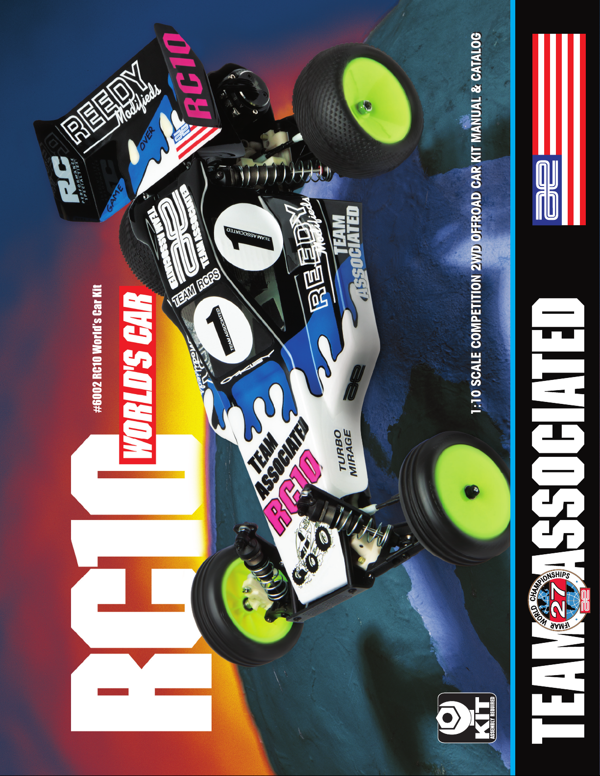
Page 1
Page 2
2
:: Introduction
Thank you for purchasing this Team Associated product. This assembly manual contains instructions and tips for building and
maintaining your new RC10 Worlds Car Kit. Please take a moment to read through this manual to help familiarize yourself with
these steps.
We are continually changing and improving our designs; therefore, actual parts may appear slightly different than in the
illustrations. New parts will be noted on supplementary sheets located in the appropriate parts bags.
Check each bag for these sheets before you start to build.
:: KIT Features
Features in the RC10 Worlds Car Kit:
• Black hard anodized 6061-T6 machined aluminum monocoque chassis
• Stealth 3-gear transmission with ball differential
• V2 slipper assembly with molded gear cover
• 16 precision ball bearings included
• Turbo Mirage body, 5.5” wing, and replica vintage decals
• V2 threaded hard anodized 6061-T6 aluminum coilover shocks with molded bleeder caps
• Independent suspension with durable long front arms and refined geometry
• In-line aluminum front axles and 30 degree caster blocks
• Fiber composite shock towers and battery strap
• Graphite transmission brace
• Updated CVA axle drivetrain
• World’s Car bellcrank steering
• 2.2” one-piece wheels
• Steel turnbuckles
:: Additional
Your new RC10 Worlds Kit comes as a kit. There are some items you
will need to complete your kit (refer to catalog for suggestions):
• R/C two channel surface frequency radio system
• Electronic Speed Control (ESC) • R/C Electric Motor
• Steering Servo • Tires with inserts
• 2S, 7.4V Lipo stick battery or 7.2V NiMH battery
• Peak detection battery charger • Thread Lock (AE # 1596)
• #2 Bit Type Phillips Screw Driver • Polycarbonate specific paint
• Pinion gear, size to be determined by type and wind of motor you use
Tools included:
• Allen wrenches (AE # 6950)
(.050”, 1/16”, 3/32”, 5/64”)
• Molded tools (AE # 6956)
• Camber gauge (AE # 1719)
:: Other Helpful Items
• Silicone Shock Fluid (Refer to catalog for complete listings) • Tire Adhesive (AE # 1597)
• Body Scissors (AE # 1737) • Reamer / Hole Punch • Wire Cutters • Hobby Knife
• FT Hex Wrenches (AE # 1655) • Needle Nose Pliers • Multi Tool (AE # 7494)
• Soldering Iron • Calipers or a Precision Ruler • Green Slime shock lube (AE # 1105)
Associated Electrics, Inc.
26021 Commercentre Dr.
Lake Forest, CA 92630
http://www.TeamAssociated.com · http://www.RC10.com · http://twitter.com/Team_Associated · http://bit.ly/AEonFacebook
Customer Service
Tel: 949.544.7500
Fax: 949.544.7501
Page 3
3
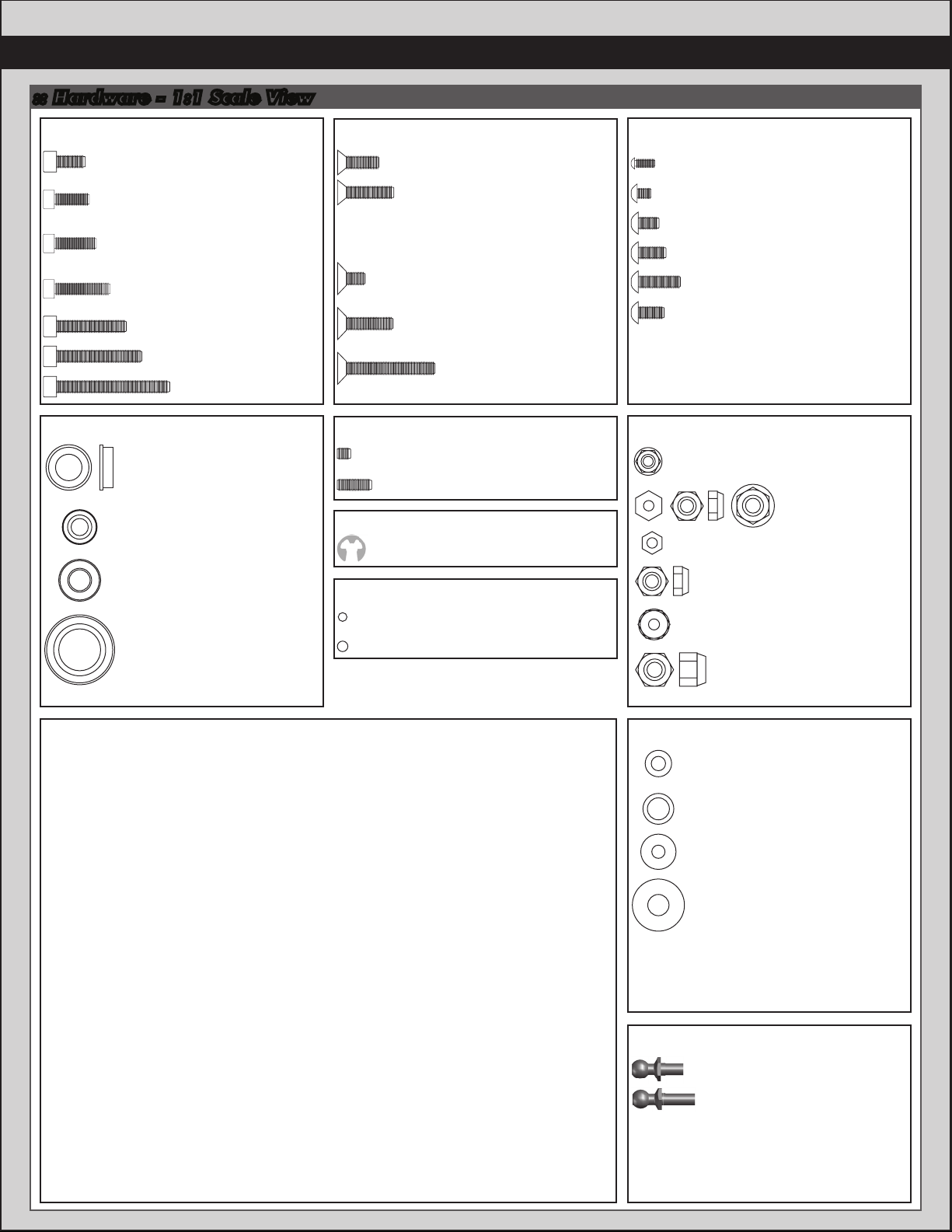
:: Hardware - 1:1 Scale View
Cap Head (shcs)
4-40x5/16” (6932)
Bushings / Bearings
Oilite Bushing Set (6630)
1/4 x 3/8 x 1/8 Flanged
5/32” x 5/16” x .125”
ball bearing (6589)
ball bearing (3977)
(PTFE bearing, 6906)
ball bearing (3976)
(PTFE bearing, 6903)
4-40x1/4 (6285)
(4145, aluminum)
4-40x3/8 (6924)
w/hole (6929)
4-40x1/2 (6925)
w/hole (6916)
4-40x5/8 (6926)
4-40x3/4 (6927)
4-40x1 (6928)
3/16” x 3/8”
3/8” x 5/8”
Flat Head (fhcs)
Flat Head (fhps)
Set Screws
Clips
Diff Balls
5/64 Diff Thrust Balls (6574)
3/32 Carbide Diff Balls (6581)
4-40x3/8 (6292)
4-40x1/2 (6922)
8-32x1/4 (6931)
8-32x1/2 (6280)
8-32x7/8 (6281)
4-40x1/8 (6951)
4-40x5/16 (4436)
E-clip 1/8 (6299)
Button Head (bhcs)
0-80x3/16 (6613)
2-56x1/8 (9645)
4-40x3/16 (6920)
4-40x1/4 (6288)
4-40x3/8 (6917)
3x6mm (31531)
Nuts (lock/plain)
4-40 Plastic Nut (6472)
4-40 Nuts (6295)
4-40 Small Pattern
Plain Nut (7260)
5-40 Diff Locknut (6629)
4-40”/5-40” nylon locknut (6222)
8-32 Steel Locknut (6952)
Notes:
Shims and Washers
.030 Nylon Spacer (4187)
3/16 Axle Shim - Silver (7368)
#4 Washer (6936)
#8 Aluminum Thick
Washer (3323)
Ballstuds
Silver .20 Short (6271)
Silver .30 Long (6273)
Page 4
4
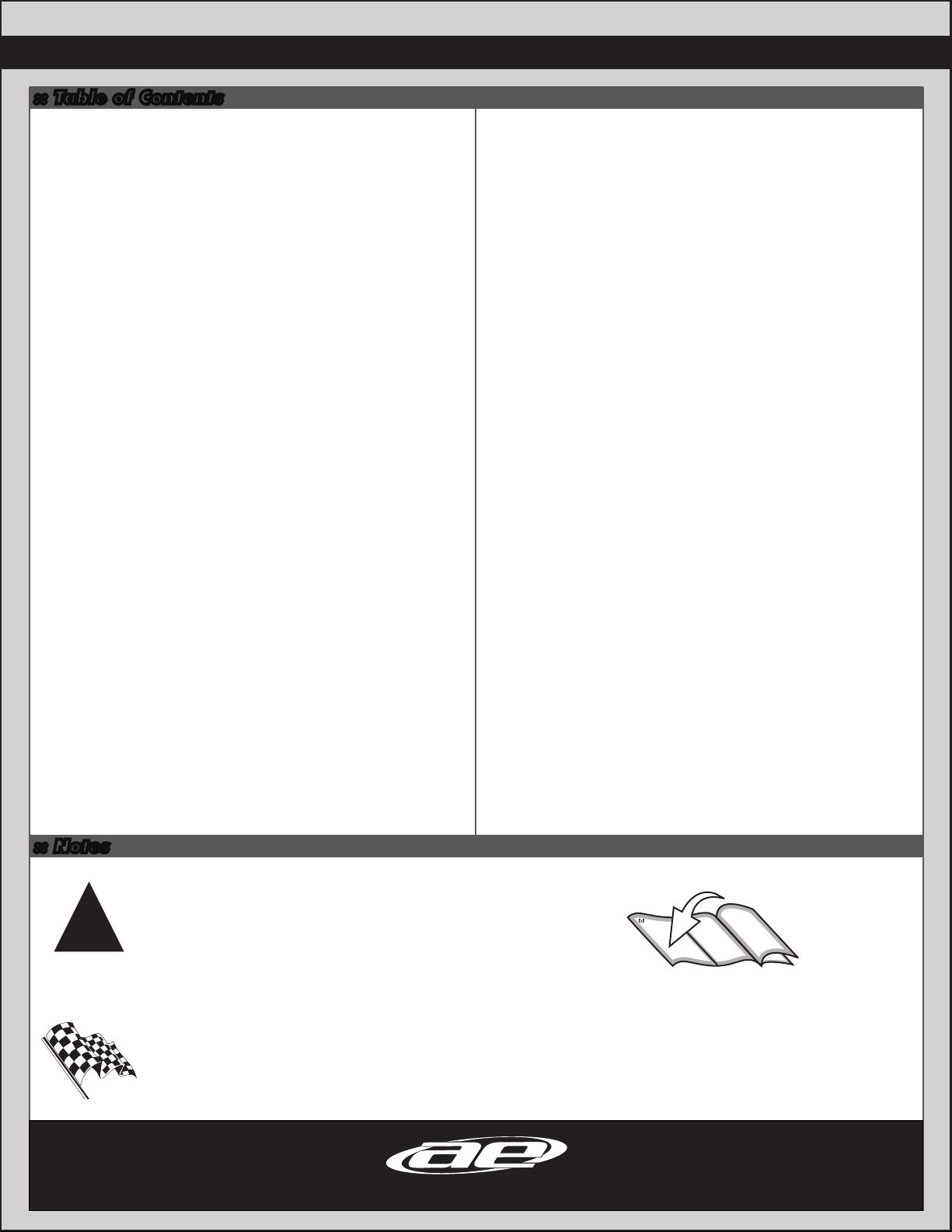
:: Table of Contents
1................... Cover
2................... Introduction
3................... 1:1 Hardware “Fold Out”
4................... Table of Contents
11 - 12........ Turnbuckles Build
(Bag F)
12 - 14........ Shocks Build
(Bag G-GG)
14 - 15 .......Chassis Build
(Bag H-HH)
5....................Nose Plate / Steering Build
(Bag A-AA)
6................... Front Suspension Build
(Bag B)
7 - 8.............Transmission Build
(Bag C-CC)
9....................Rear Bulkhead Build
(Bag D-DD)
10 - 11.........Rear Suspension Build
(Bag E)
15 - 16........ Servo Build
(Bag I)
16 - 17........ Wheels, Tires and Body Install
(Bag J)
18 - 19........ Tuning Tips
20 - 28....... Catalog
29................ Setup Sheet “Blank”
30................ Back Cover
:: Notes
This symbol indicates a special
note or instruction in the manual.
!
There is a 1:1 hardware foldout page in the
front of the manual. To check the size of a part,
This symbol indicates a Racers Tip.
Associated Electrics, Inc.
26021 Commercentre Dr.
Lake Forest, CA 92630
http://www.TeamAssociated.com · http://www.RC10.com · http://twitter.com/Team_Associated · http://bit.ly/AEonFacebook
line up your hardare with the correct drawing
until you find the exact size. Each part in the
foldout has a number assigned to it for ordering
replacement parts.
Customer Service
Tel: 949.544.7500
Fax: 949.544.7501
Page 5
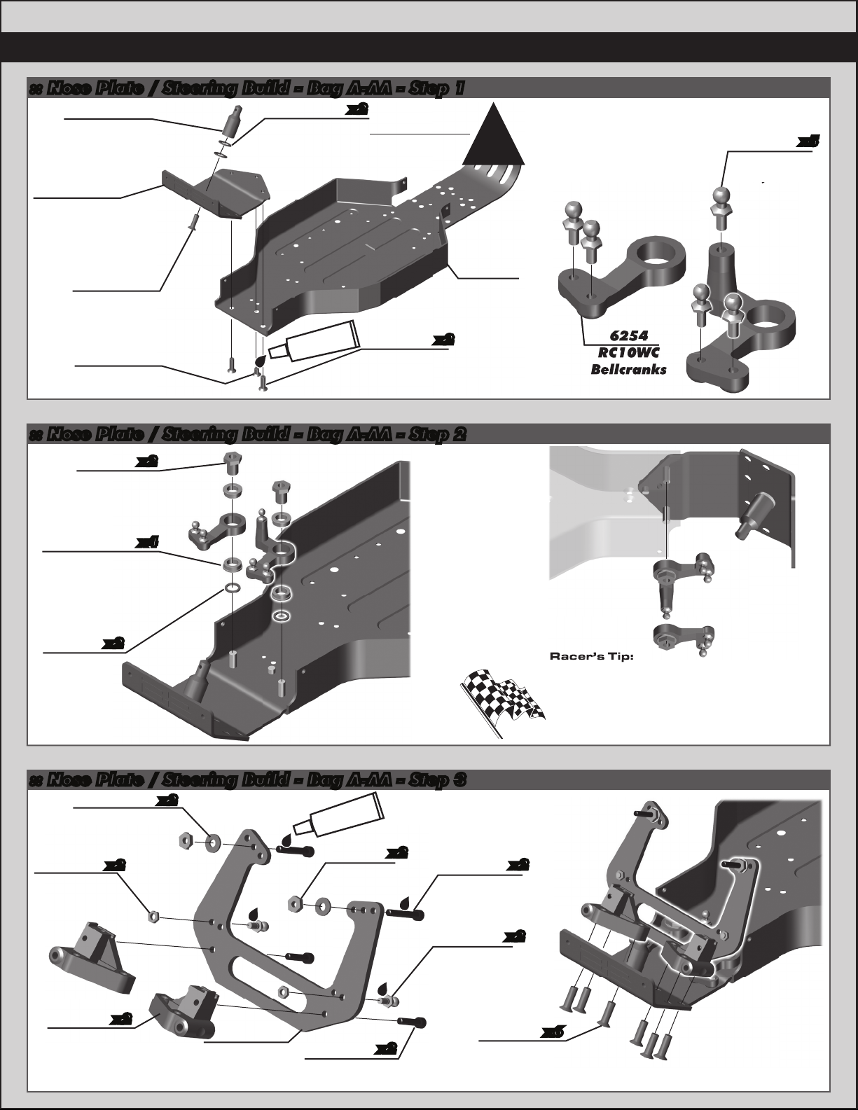
6254
RC10WC
Bellcranks
.20 (silver)
2/14
:: Nose Plate / Steering Build - Bag A-AA - Step 1
6331
RC10 Body
Mounts
(white)
6309
RC10WC
Front Nose
Plate,
(black)
6280
8-32 x 1/2
Aluminum
FHPS
6931
8-32 x 1/4
FHPS
3323
#8 Aluminum
Washer (thick)
#1596
thread lock
x2
6280
8-32 x 1/2
Aluminum
FHPS
x2
:: Nose Plate / Steering Build - Bag A-AA - Step 2
!
6302
RC10WC
Chassis,
(black)
You can use 2 or 3
#3323 #8 washers
based on body height
preference.
6254
RC10WC
Bellcranks
5
6271
Ballstud
.20 (silver)
x5
6254
x2
Bellcrank
Bushing
Nut
6630
x4
Flanged Oilite
Bushing,
(.25 x .375 x .125)
6254
x2
Bellcrank
Shim
:: Nose Plate / Steering Build - Bag A-AA - Step 3
6936
#4 aluminum
washer
7260
x2
4-40 Plain
Nut
x2
#1596
thread lock
6295
4-40 Nut
x2
4-40 x 3/4
6927
SHCS
Racer’s Tip:
Hold the chassis and bulkhead
assemblies upside down during
install to ensure the #6254
bellcrank shims are correctly seated.
Tighten down the bushing and then
loosen until bellcrank turns freely.
x2
6208
RC10 Front
Arm Mounts
(Left & Right)
x2
6232
RC10WC
Front Shock
Tower
6925
x2
4-40 x 1/2
SHCS
6271
Ballstud
.20 (silver)
6280
8-32 x 1/2
Aluminum
FHPS
x2
x6
Page 6
6
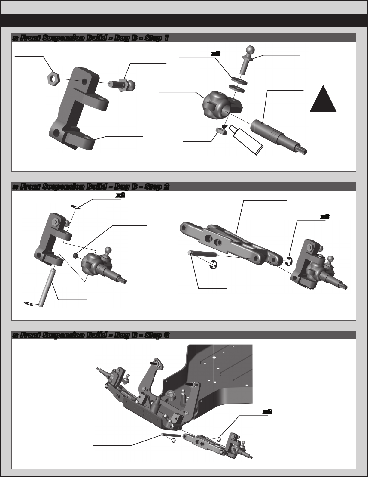
:: Front Suspension Build - Bag B - Step 1
7260
4-40
Plain
Nut
Build left and
LEFT LEFT
6210
RC10 front
caster blocks,
30 degrees
(Left & Right)
6273
Ballstud
.30 (silver)
right sides!
:: Front Suspension Build - Bag B - Step 2
6299
E-clip
(small)
x2
6951
4-40 x 1/8
Set Screw
#4 Washer,
Aluminum
6225
RC10WC
Inline
Steering
Blocks
6936
7260
4-40
Plain
Nut
x2
.30 (silver)
#1596
thread lock
6206
RC10WC
Front Arms,
(black)
(Left & Right)
6273
Ballstud
7222
Wide Front
Axle
Press stub axles
into steering blocks.
Use a hard surface
to push down on!
Build left and
(small)
!
right sides!
6299
E-clip
x2
6223
RC10
King Pins
:: Front Suspension Build - Bag B - Step 3
6226
RC10 Front
Inner Hinge
Pins
6227
RC10 Front
Outer
Hinge Pins
6299
E-clip
(small)
Build left and
right sides!
x2
Build left and
right sides!
Page 7
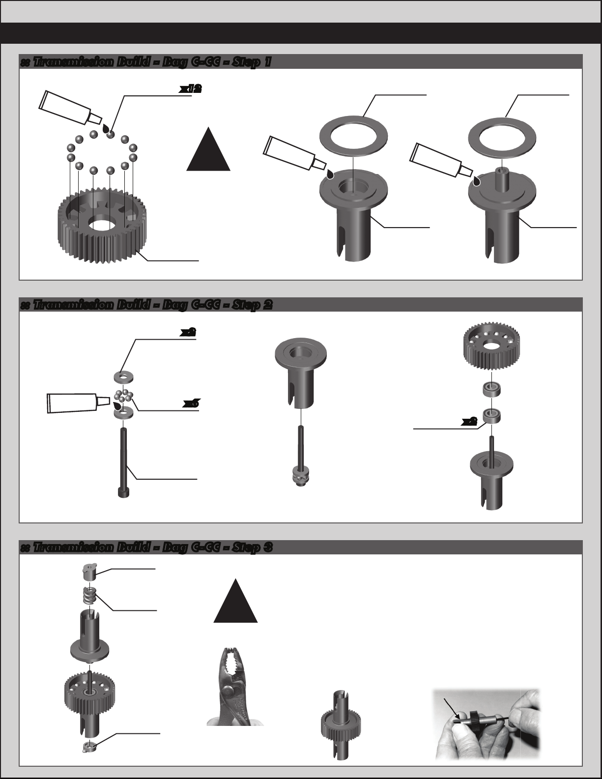
:: Transmission Build - Bag C-CC - Step 1
7
x12
#6591
diff lube
6581
3/32 carbide
diff balls
!
The diff gear has four
molded dimples on
one side. The diff balls
should be installed on
the opposite side of
the dimples.
6580
Diff Gear
:: Transmission Build - Bag C-CC - Step 2
6573
Diff thrust
washer
x2
#6591
diff lube
6579
Diff Drive
Ring
6577
Diff
Outdrive
(Right)
#6591
diff lube
6579
Diff Drive
Ring
6578
Diff
Outdrive
(Left)
#6588
black grease
6574
x6
5/64 diff
thrust
balls
6573
Diff thrust
bolt
:: Transmission Build - Bag C-CC - Step 3
6575
Locking
t-nut
6582
Diff
thrust
spring
!
Compress
spring first.
6589
x2
Bearing,
5/32 x 5/16
As you tighten the diff bolt, you will notice the
T-nut ears moving closer to the bottom of the
outdrive slot. This compresses the spring
behind the T-nut. The spring should be
completely compressed at the same time the
T-nut reaches the end of the slot.
Caution! Pay close attention to the feeling
when the spring is completely compressed.
Do not overtighten the bolt. When you feel the
spring completely compressed, loosen the diff
bolt 1/4” of a turn. Your diff should now operate
smoothly with resistance as the outdrives move
in opposite directions. After you have driven the
car once, re-check the diff setting.
6575
Diff
cover
Page 8
8
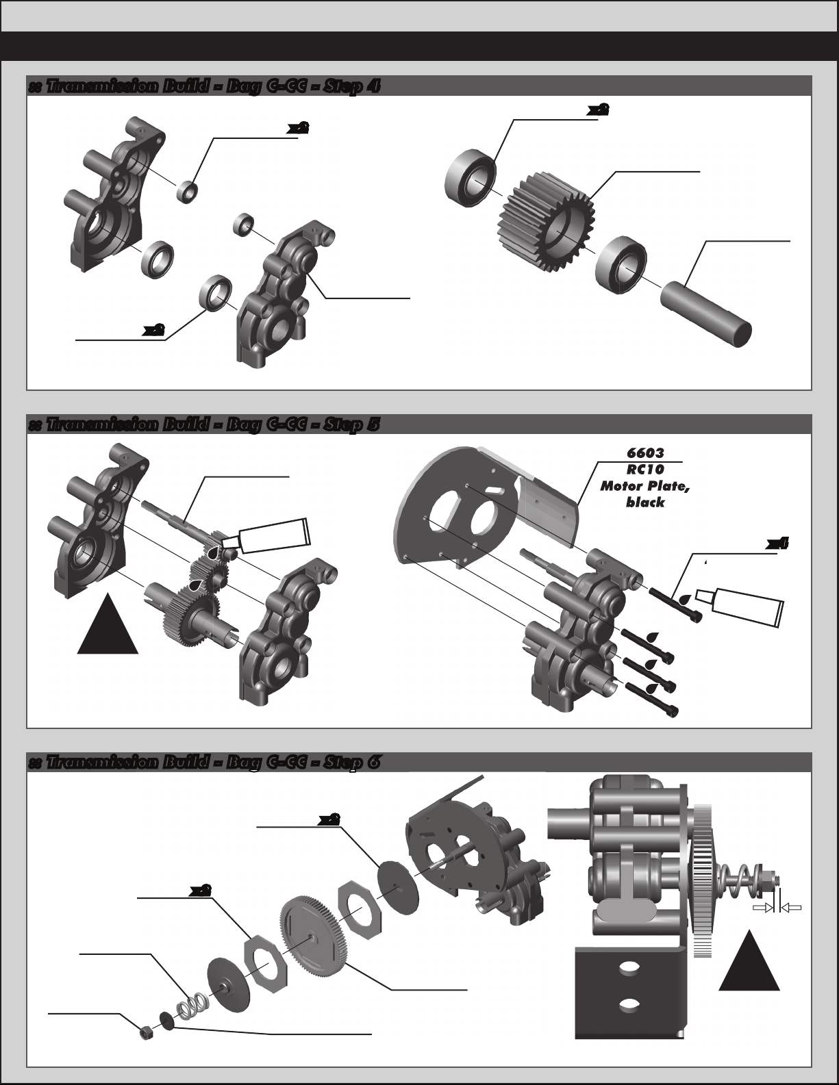
- Bag C-CC
- Step 6
4-40 x 1”
RC10
Motor Plate,
black
:: Transmission Build - Bag C-CC - Step 4
3977
Bearing,
3/16 x 3/8”
3976
Bearing,
3/8 x 5/8”
x2
:: Transmission Build - Bag C-CC - Step 5
x2
6564
RC10WC
Transmission
Case
(L & R sides)
3977
Bearing,
3/16 x 3/8”
x2
6569
RC10WC
Idler Gear
9361
Idler Gear
Shaft
9601
Top Shaft
#6591
diff lube
!
Note: The head
of the diff bolt
should be on the
same side as
the spur gear!
:: Transmission Build - Bag C-CC - Step 6
7485
V2 Slipper
Hubs
x2
6603
RC10
Motor Plate,
black
6928
4-40 x 1”
SHCS
#1596
thread lock
x4
6629
5-40 Diff
Locknut
9739
Slipper
Spring
9603
Slipper
Pads
x2
7486
Slipper Spring
Washer
9651
81T 48P
Spur Gear
1mm
!
There should be
1mm of thread
exposed for
stock slipper
setup.
Page 9
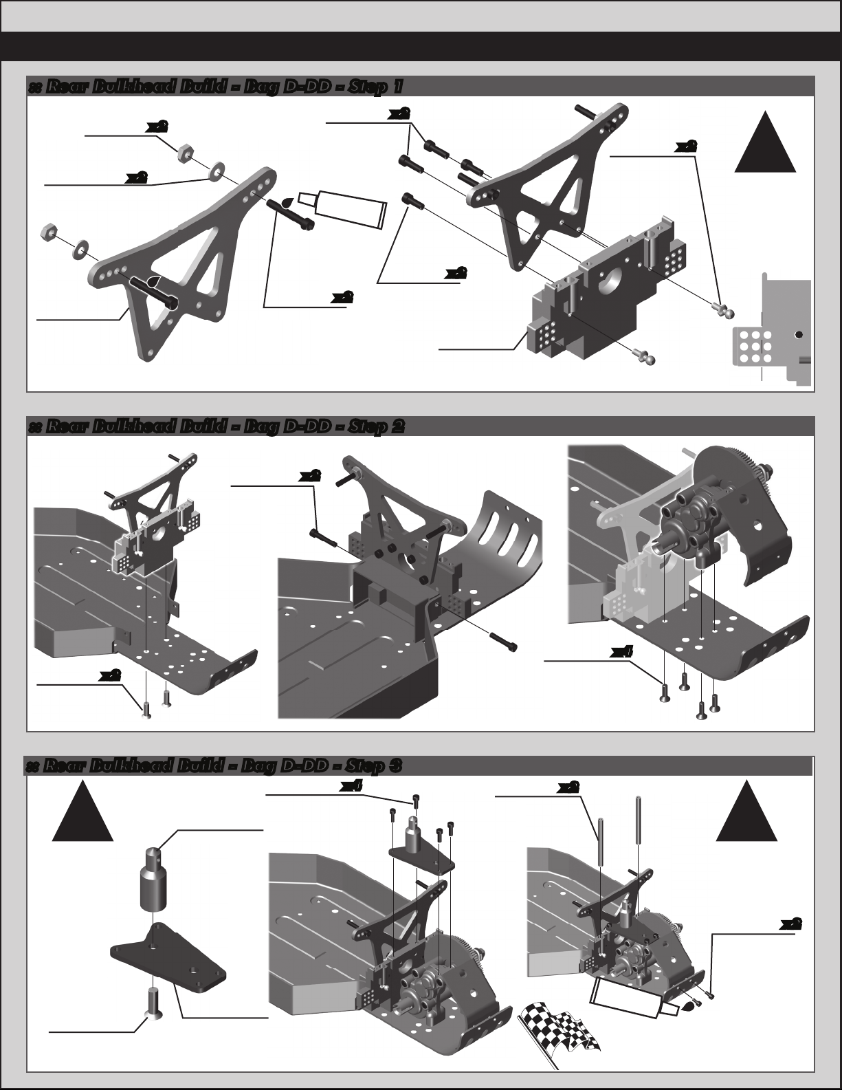
:: Rear Bulkhead Build - Bag D-DD - Step 1
9
6295
4-40 Nuts
6936
x2
#4 Aluminum
Washer
6377
RC10WC
x2
4-40 x 3/8
thread lock
6927
4-40 x 3/4
SHCS
6924
SHCS
#1596
x2
x2
4-40 x 5/16
Rear Shock
Tower
:: Rear Bulkhead Build - Bag D-DD - Step 2
6926
4-40 x 5/8
SHCS
x2
6932
SHCS
RC10 Rear
Bulkhead
x2
6323
6271
x2
Ballstud
.20 (silver)
!
Cut the
bulkhead for
a more
authentic look
to the original
Worlds car.
6280
x2
8-32 x 1/2
FHPS
:: Rear Bulkhead Build - Bag D-DD - Step 3
x4
Note: The
transmission
brace does
not have a
counter sink
for the
#6280 screw.
6280
8-32 x 1/2
FHPS
6331
RC10 Body
Mounts
(white)
6593
RC10WC
Transmission
Brace
6932
4-40 x 5/16”
SHCS
6292
x4
4-40 x 3/8”
FHCS
* These screws are
from Bag C
6327
x2
RC10
Wing
Tubes
#1596
thread lock
Racer’s Tip:
Use a small amount of CA
glue on wing tube ends before
inserting into bulkhead.
!!
Press wing
tubes into
bulkhead!
6285
4-40 x 1/4
SHCS
x2
Page 10

10
holes
Build left and
:: Rear Suspension Build - Bag E - Step 1
6360
RC10 Rear
Arm Mounts
6380
RC10 Rear
Inner
Hinge Pins
6355B
RC10WC
Rear Arms,
(black)
x2
Build left and
6299
E-clip
(small)
right sides!
:: Rear Suspension Build - Bag E - Step 2
9760
CVA
Bone
Remove pin retainer to
prevent binding if using
9755
CVA
Axle
#6588
black grease
4-40 set screw in CVA.
!
Note:
!
7381
CVD
Pin
#1597
ca glue
1 drop!
x2
6280
8-32 x 1/2
FHPS
CA glue not
included
Forward
holes
!
Build left and
right sides!
!
Align the gap in
the pin retainer
to be opposite of
the CVA pin.
7381
CVD
Coupler
Retainer
Build x2
:: Rear Suspension Build - Bag E - Step 3
7364
9608
Rear Axle
Wheel Spacer,
blue
aluminum
RC10WC 0°
Rear Hub
7377
Rear Axle Bearing
Spacer, aluminum
7996
CVA Pin
7368
Rear Axle
(Universal)
Shims,
3/16 X .010”
3/16” X 3/8”
x3
3977
Bearing,
x2
Drive Shaft
7665
Roll Pin
Racer’s Tip:
Use a small amount of CA
glue on CVA Pin Retainer ends
to hold retainer in place.
6273
Ballstud
.30 (silver)
7260
4-40
Plain Nut
Build left and
right sides!
Page 11

:: Rear Suspension Build - Bag E - Step 4
6381
RC10 Rear
Outer
Hinge
Pins
:: Turnbuckles Build - Bag F - Step 1
Note:
The servo turnbuckle will be set aside and built
when the servo is built and installed into the
chassis on page 15.
6279
White Ball
Cups
x2
6260
Turnbuckle,
1.00”
!
Orient the notch
to the left
throughout the
car. It indicates
which end has the
left hand threads!
6299
E-clip
(small)
11
x2
Build left and
right sides!
Steering Rack Turnbuckle
0.45” (11.5mm)
:: Turnbuckles Build - Bag F - Step 2
6264
Turnbuckle,
1.375”
Rear Camber Turnbuckle
0.98” (25mm)
Build left and
right sides!
6279
Ball cups
(white)
x2
!
Orient the notch
to the left
throughout the
car. It indicates
which end has the
left hand threads!
Page 12

12
:: Turnbuckles Build - Bag F - Step 2
6262
Turnbuckle,
1.65”
Front Camber Turnbuckle
0.86” (22mm)
Build left and
right sides!
:: Turnbuckles Build - Bag F - Step 3
6263
Turnbuckle,
2.06”
6279
Ball cups
(white)
Orient the notch
throughout the
car. It indicates
which end has the
left hand threads!
6279
Ball cups
(white)
x2
!
to the left
x2
Steering Turnbuckle
1.45” (37mm)
Build left and
right sides!
:: Shocks Build - Bag G-GG - Step 1
Remove
spurs
6465
Shock
pistons
(1, 2, 3)
Piston
1
Piston number here
Use #1 = front shocks
Use #1 = rear shocks
6460
Shock shaft,
front (0.71)
6459
Shock shaft,
rear (1.02)
!
Orient the notch
to the left
throughout the
car. It indicates
which end has the
left hand threads!
6299
E-clip
(small)
6299
E-clip
(small)
Racer’s Tip:
Use a marker to mark
the piston numbers for
easy identification!
Page 13

:: Shocks Build - Bag G-GG - Step 2
13
6469
Shock cap
o-ring
5407
x2
Red
O-ring
4187
Nylon
Spacers
Front: 0
Rear: 3
7484
Shock
Bottom
Cap
:: Shocks Build - Bag G-GG - Step 3
Shock fluid
35wt #5429
Shock fluid
35wt #5429
6428
Shock
cap
(molded)
Step 2-3
7438
V2 .71
Threaded
Body (front)
7481
V2 1.32
Threaded
Body (rear)
7484
Shock
Internal
Spacer
* Shock Bleeding Steps:
1. Before assembly, get each bleed
screw and thread it 1-2 turns into
the shock cap. This will make
installation easier when you are
bleeding your shocks.
2. Pull shock shaft down.
3. Fill shock body 3/4 full with silicone fluid.
4. Slowly move the shock shaf t up and
down to remove air from under piston.
5. Wait for bubbles to come to surface
6. Fill shock body to top with silicone fluid
7. Place a drop of oil in the cap and on cap
thread
8. Install cap (without bleed screw) and
tighten completely
9. Slowly compress shaf t all the way to
bleed excess silicone fluid out the hole
in the cap (use rag around shock to
catch excess fluid)
10. Install 2-56 button head screw until
snug while shaft is fully compressed
Step 8 Step 9-10Step 6-7Step 4-5
(recommend using a high quality .050”
wrench such as Factory Team #1542)
5407
Red O-ring
(use for
rear shocks
only)
6468
Shock
6471
Pivot Ball
Shock
Rod End
Build x2 front and x2 rear shocks
9645
2-56 x 1/8”
BHCS
Slow
:: Shocks Build - Bag G-GG - Step 4
Racer’s Tip:
Use your finger to rub shock
oil on the o-ring for smoother
adjustment!
3959
Shock Collar
O-Ring
7416
Threaded
Shock Collar
6496
Front shock
spring, silver
(3.85lb)
6478
Rear shock
spring, silver
(2.10lb)
9724
Offset
Shock Cups
(front)
Front:
5mm
Rear:
1mm
6475
Shock Cups
(rear)
Build x2 front and x2 rear shocks
Page 14

14
:: Shocks Build - Bag G-GG - Step 5
6472
Plastic Nut
6927
4-40 X 3/4”
SHCS
:: Shocks Build - Bag G-GG - Step 6
6473
Shock
Bushing
Install two
front shocks!
6473
Shock
Bushing
6472
Plastic Nut
6927
4-40 X 3/4”
SHCS
:: Chassis Build - Bag H-HH - Step 1
1
6288
4-40 x 1/4
BHCS
#1596
thread lock
6936
#4 Washer,
aluminum
x2
!
Note: Use the two washers
(#6936) when running the
long wheelbase.
Remove both washers when
running the short wheelbase.
6337
RC10
Antenna
Mount
Antenna tube
Install two
rear shocks!
6338
and cap,
(black)
6321
RC10WC Nose
Brace Tubes,
(black)
2
6917
4-40 x 3/8
BHCS
Build left and
right sides!
4187
Nylon
Spacer
6922
4-40 x 1/2”
FHCS
Page 15

:: Chassis Build - Bag H-HH - Step 2
15
6333
RC10
Battery
Cup
6292
4-40 x 3/8”
FHCS
:: Chassis Build - Bag H-HH - Step 3
x2
6925
4-40 x 1/2”
SHCS
Battery not
included!
x2
6339
RC10WC
Battery
Strap
!
Note: You can sand the end
of the battery strap to better
fit between the battery pack
and the rear bulkhead.
Rear of Battery Strap
:: Servo Build - Bag I - Step 1
6337
RC10
Servo
Mounts
Servo not
included!
x2
6924
4-40 x 3/8”
SHCS
6936
#4 Aluminum
Washer
x4
x4
89007
Servo Horn
Ring
6271
Ballstud
.20 (silver)
9180
Servo Horn,
molded
screw not
included!
Note:
The servo turnbuckle and ball cups are left over
from bag F.
6279
Ball cups
(white)
x2
6262
Turnbuckle,
1.65”
Servo Turnbuckle
Servo
horn
0.94” (24mm)
Page 16

16
:: Servo Build - Bag I - Step 2
Receiver
not
included!
ESC not
included!
6922
4-40 x 1/2”
FHCS
x2
:: Wheels / Tires and Body - Bag J - Step 1
Motor not
included!
!
See page 18
to set gear
mesh properly!
Pinion not
included!
31531
3 x 6mm
BHCS
x2
6285
4-40 x 1/4”
SHCS
x2
6727
Servo tape
x2
RC10WC
Gear Cover
and Plug
6566
:: Wheels / Tires and Body - Bag J - Step 2
#1597
ca glue
Tires and
Inserts not
included!
!
Once the tire is mounted
to the wheel, carefully
apply ca glue to the tire
bead. Do one side at a
9688
Front Wheel
Build 2 Build 2
2.2”, yellow
time. Allow it to dry
before gluing the
other side!
#1597
ca glue
6805Y
Rear Wheel
3/16”, yellow
Tires and
Inserts not
included!
Page 17

:: Wheels / Tires and Body - Bag J - Step 3
17
3977
Bearing,
3/16” X 3/8”
x2
Build left and
right sides!
:: Wheels / Tires and Body - Bag J - Step 4
Painting Tips:
Body and Wing:
Your RC10 Worlds Kit comes with a clear polycarbonate
body and wing. You will need to prep the body and wing
before you can paint them. Wash the inside thoroughly
with warm water and liquid detergent. Dry the body and
wing using a clean, soft, lint-free cloth. Install the window
masks on the inside of the body. (RC cars get painted
from the inside). Using high quality masking tape, apply
tape to the inside of the body to create a design. Spray
(either rattle can or airbrush R/C specific paint) the paint
to the inside of the body (prefferably dark colors first,
lighter colors last).
NOTE: use ONLY paint that is recommended for use with
(polycarbonate) plastics. If you do not, you can
destroy the plastic body and wing!!!!).
6222
4-40/5-40
Nylon Locknut,
black
6952
8-32 Steel
Locknut
Build left and
right sides!
6332
Body
x2
clip
After painting, cut the body and wing along the trim lines.
Make sure to drill or use a body reamer to make the
holes for the body mounts, wing mounts, and antenna!
:: Wheels / Tires and Body - Bag J - Step 5
6182
Wing,
clear
6189
Wing
mounts
x2 x2
!
4436
4-40 x 5/16”
Set Screw
TIP: Bending the
wire as shown can
help ensure the wing
buttons are parallel.
6189
Wing mount
wire
create tight fit inside
!
TIP: Bend wire to
wing tubes.
Page 18

18
:: Tuning Tips
Tips for Beginners:
Before making any changes to the standard setup, make sure you can get around the track without crashing.
Changes to your vehicle will not be beneficial if you can’t stay on the track. Your goal is consistent laps. Once you can get
around the track consistently, start tuning your vehicle. Make only ONE adjustment at a time, testing it before making another change. If the result of your adjustment is a faster lap, mark the change on the included setup sheet (make
adddtional copies of the sheet before writing on it). If your adjustment results in a slower lap, revert back to the previous
setup and try another change. When you are satisfied with your vehicle, fill in the setup sheet thoroughly and file it away.
Use this as a guide for future track days or conditions.
Peridicaly check all moving suspension parts. Suspension components must be kept clean and move freely without
binding to prevent poor and/or inconsistent handling.
Motor Gearing:
Proper motor gearing will result in maximum performance and run time while reducing the chance of overheating and
premature motor failure. The gear ratio chart lists recommended starting gear ratios for the most widely used motor
types. Gear ratios will vary depending upon motor brand, wind, and electronic speed control. Consult your motor and
electronic speed control manufacturers for more information. Team Associated is not responsible for motor damage
due to improper gearing. * These gearings are for use with advanced timing speed control settings!
RC10WC Gear Ratio Chart (Internal Gear Ratio 2.25:1)
FDRSpurPinionMotor
27T Stock Brushed
19T Super Stock Brushed
17.5 Reedy Sonic Brushless *
17.5 Reedy Sonic Brushless
13.5 Reedy Sonic Brushless *
13.5 Reedy Sonic Brushless
10.5 Reedy Sonic Brushless
9.5 Reedy Sonic Brushless
8.5 Reedy Sonic Brushless
Due to the original design of the RC10, motors exceeding the power of a 8.5T
motor are NOT recommended, to prevent damage to the drivetrain!
20
19
21
30
19
28
21
20
19
81
81
81
81
81
81
81
81
81
9.11:1
9.59:1
8.68:1
6.08:1
9.59:1
6.51:1
8.68:1
9.11:1
9.59:1
Set The Gear Mesh:
You should be able to rock the spur gear back and forth in the teeth of the pinion gear without making the pinion gear
move. If the spur gear mesh is tight, then loosen the #31531 screws and move the motor away, then try again.
A gear mesh that is too tight or too loose will reduce power and damage the gear teeth.
Slipper Clutch:
The assembly instructions give you a base setting for your clutch.
Turn the nut on the shaft so that the end of the top shaft is even with the
outside of the nut. Tighten the nut until the shaft extends thru the nut by
0.5mm. At the track, tighten or loosen the nut in 1/8 turn increments, until
you hear a faint slipping sound for 1-2 feet on takeoffs.
Another popular way to set the clutch is to hold both rear tires firmly in place
and apply short bursts of throttle. If the clutch is properly set, the front tires
should lift slightly up off the surface.
Wheelbase Adjustment:
The wheel base on the RC10WC can be adjusted by moving the rear arm mounts forward or backwards.
The kit setting has the arm mount back which provides the most stability over bumps and rhythm sections.
Going to the shorter wheelbase option will improve rear traction.
Page 19

19
:: Tuning Tips (cont.)
Front Camber Links:
Changing the length of the camber link is considered a bigger step than adjusting the ball end height on the tower.
Shortening the camber link will give the front end less roll and quicken steering response. Lengthening the camber link
(or raising the ball end) will give the front more roll and slower steering response.
Front Camber:
Camber describes the angle at which the tire and wheel rides when
looked at from the front. Negative camber means that the tire leans
inward at the top. A good starting camber setting is -1°. Use the
included #1719 camber gauge to set your camber. Positive camber,
where the top of the tire is leaning out, is not recommended.
*Checking camber
with camber gauge
Caster:
Caster describes the angle of the kingpin as it leans toward the rear of the vehicle. Positive caster means the kingpin
leans rearward at the top. The supplied 30° caster blocks (#6210) are recommended in most cases. For less corner
entry steering and more exit steering, try the optional 15° caster blocks (#6213).
Rear Camber Link:
Changing the length of the camber link is considered a bigger step than adjusting the ball end height on
the rear chassis brace. Shortening the camber link (or lowering the ball end) will give the rear end less
roll and the car will tend to accelerate or “square up” better. Lengthening the camber link (or raising
the ball end) will give the rear more roll and more cornering grip. In order to run some of the very short
link locations, a shorter turnbuckle will be required.
!
!
*Raise or lower
the ball end by
adjusting the
ballstud location
on the bulkhead
Rear Camber:
Camber describes the angle at which the tire and wheel rides when looked at from the back. Negative camber means
that the tire leans inward at the top. A good starting camber setting is -1°. Use the included #1719 camber gauge to
set your camber. Adding a small amount of positive camber, where the top of the tire is leaning out, will tend to improve
straight-line acceleration on loose tracks.
Ride Height:
Ride height is the distance from the ground to the bottom of the
chassis. The standard front ride height setting is with the front arms
just below level or 24mm (Ride Height Gauge #1449). Check the
ride height by lifting up the entire car about 8-12 inches off the bench
and drop it. After the suspension “settles” into place, measure ride
height (Ride Height Gauge #1449). Raise or lower the shock collars
as necessary so that the left & right arms appear to be level.
The rear ride height setting you should use most often is with the
outdrive, driveshaft, and axles all on the same imaginary horizontal
line (reffered to as “bones level”) or 24mm (Ride Height Gauge
#1449). Check the ride height by lifting up the entire car about 8-12
inches off the bench and drop it. After the suspension “settles” into
place, measure ride height (Ride Height Gauge #1449). Raise or
lower the shock collars as necessary so that the left & right
driveshafts appear to be level.
*Front arms should
be just below level
*Dog bones should
be in a straight line
when ride height is
set at “Bones level”
*TIP: Set the rear dog bones level and then
adjusting the front to make the chassis
!
parallel to the ground.
!
ride height
!
Motor Maintenance:
Brushed motors require frequent maintenance to keep performance levels at their maximum. Between runs and after
letting the motor cool completely, inspect the brushes to ensure that they are moving freely in their holders. Remove
the springs and slide the brushes in and out of their holders checking for any resistance or rough spots. If found,
remove the brush and carefully wipe it clean. Removing buildup will allow the brush to slide freely and create maximum
contact with the commutator resulting in maximum power output. After every 3-5 runs, remove the brushes from
their holders and inspect the tips for wear or burning. If there is noticeable wear (less than 75% of the brush
remaining), it is best to cut the commutator and replace the brushes with a new pair. If the tips become a burned blue
color, the lubricant in the brush has been burned away and new brushes should be installed. Occasionally, the motor
should be cleaned with a soft brush to prevent dirt build up around the brush hood area and ball bearings.
At this time, it is a good idea to add one drop of bushing / bearing oil to each bushing or ball bearing.
If using a brushless motor, please refer to the motor manufacturer’s guidelines for proper maintenance.
Page 20

20
:: Shocks
3959
4187
5407
6299
6428
6459
6460
6465
6468
6469
6471
6475
7416
7438
7481
7484
9645
9724
Threaded Shock Collar O-Ring
Nylon Spacer, 1/32” (.030)
Red O-Rings
1/8” E-Clips
Shock End Cap, molded composite
Shock Shaft, 1.02” stroke
Shock Shaft, .71” stroke
Shock Piston, (1, 2, 3)
RC10 Shock Rod Ends / Pivots
Black O-Ring
Rod End, .230 ball, for 2 shocks
Shock Cups (4)
FT Off Road Threaded Shock Collar
with O-Rings, black
FT V2 .71 Threaded Bodies
FT V2 1.32 Threaded Bodies
FT V2 1:10 Shock Rebuild
2-56 x 1/8” BHCS
Offset Spring Cup
4
12
8
12
1
1
1
4ea.
2
4
2
1
2
2
2
4
6
2
6428
9645
6469
Front: 7438
Rear: 7481
6299
6465
6299
Front: 6460
Rear: 6459
3959
7416
Front: 9724
Rear: 6475
:: Springs
1581
1582
6493
6494
6496
6497
8232
6478
6480
6481
6482
7434
7435
7436
Factory Team Buggy Front Spring Kit. I pr
of green, silver, blue, black springs
Factory Team Truck/Buggy Rear Spring Kit.
I pr of green, silver, blue, gold, red springs
Front Buggy Spring Brown 2.80 lb
Front Buggy Spring Green 3.50 lb
Front Buggy Spring Silver 3.85 lb (Kit)
Front Buggy Spring Blue 4.20 lb
Front Buggy Spring Black 3.20 lb
Rear Spring Silver 2.10 lb (Kit)
Rear Spring Green 1.90 lb
Rear Spring Black 1.74 lb
Rear Spring Gray 2.33 lb
Rear Spring Blue 2.55 lb
Rear Spring Gold 2.75 lb
Rear Spring Red 2.95 lb
:: Slipper / Gear Cover
6285
6566
6629
7485
7486
9603
9648
9649
9650
9651
9652
9653
9739
31531
4-40 x 1/4 SHCS
RC10WC Gear Cover
5-40 Diff Locknut
FT V2 Slipper Hubs
FT V2 Slipper Spring and Washer
Slipper Pad
69T 48P Spur Gear
72T 48P Spur Gea
75T 48P Spur Gear
81T 48P Spur Gear (Kit)
78T 48P Spur Gear
84T 48P Spur Gear
Slipper Spring
M3 x 6 BHCS
12
1
6
2
1
2
1
1
1
1
1
1
1
6
5407
7484
5407
7484
1
1
Pr.
Pr.
Pr.
Pr.
Pr.
Pr.
Pr.
Pr.
Pr.
Pr.
Pr.
Pr.
7485
9603
4187
5407
:: Shock Fluid
5420
5421
5422
5423
5424
5425
5426
5427
5428
5429
5430
5431
5432
5433
5434
5435
5436
5437
5438
10 Weight Silicone Shock Fluid
20 Weight Silicone Shock Fluid
30 Weight Silicone Shock Fluid
40 Weight Silicone Shock Fluid
22.5 Weight Silicone Shock Fluid
80 Weight Silicone Shock Fluid
27.5 Weight Silicone Shock Fluid
15 Weight Silicone Shock Fluid
25 Weight Silicone Shock Fluid
35 Weight Silicone Shock Fluid
45 Weight Silicone Shock Fluid
55 Weight Silicone Shock Fluid
32.5 Weight Silicone Shock Fluid
37.5 Weight Silicone Shock Fluid
42.5 Weight Silicone Shock Fluid
50 Weight Silicone Shock Fluid
60 Weight Silicone Shock Fluid
70 Weight Silicone Shock Fluid
47.5 Weight Silicone Shock Fluid
9603
9739
9651
7485
6471
7486
6468
2oz.
2oz.
2oz.
2oz.
2oz.
2oz.
2oz.
2oz.
2oz.
2oz.
2oz.
2oz.
2oz.
2oz.
2oz.
2oz.
2oz.
2oz.
2oz.
6629
6566
31531
*Motor
screws
6566
6285
Page 21

:: Turnbuckles / Servo
6260
6262
6263
6264
6271
6279
6337
6922
6924
6936
9180
89007
Turnbuckle, 1.00”
Turnbuckle, 1.65”
Turnbuckle, 2.06”
Turnbuckle, 1.375”
Short Ballstud, stainless steel, short
White Ball Cups
RC10 Servo/Antenna Mount
4-40 x 1/2” FHCS
4-40 x 3/8” SHCS
#4 Washer, Aluminum
Servo Horns, Molded
Steering Servo Horn Ring
12
14
10
21
2
2
2
2
1
6
6
1
1
6337
6922
6337
6922
6924
6936
6924
6271
:: Steering
6254
6271
6280
6630
RC10WC Bellcrank Set
Short Ballstud, stainless steel, short
8-32 x 1/2” Aluminum FHPS
RC10 Oilite Bushing Set
6260
6262
6263
6264
6936
89007
62796279
9180
*Not included
1
12
16
1
6271
6254
6254
6630
6630
6271
6271
6254
6630
6254
6254
6630
6280
6254
6280
:: Antenna Mount / Battery Strap
4187
6292
6333
6337
6338
6339
6925
Nylon Spacer, 1/32” (.030)
4-40 x 3/8” FHCS
RC10 Battery Cup
RC10 Servo/Antenna Mounts
Antenna Tube with Cap, black
RC10WC Battery Strap
4-40 X 1/2” SHCS
12
6
1
1
1
1
6
6338
6338
6337
4187
6292
6925
6292
6925
6339
6333
6292
Page 22

22
:: Front Arm
3977
6206
6208
6210
6222
6223
6225
6226
6227
6273
6280
6299
6927
6936
6951
7222
7260
Bearing, 3/16” X 3/8”
Front Suspension Arm, wide, black
RC10 Front Arm Mounts
RC10 Front Caster Blocks, 30 deg
4-40/5-40 Nylon Locknut, black
RC10 King Pin w/Clips
RC10WC Inline Steering Block
RC10 Front Inner Hinge Pin
Hinge Pin, outer, 1.020”, w/ clips
Long Ballstud, .17 Ball Stud
8-32 x 1/2” Aluminum FHPS
E-Clip, 1/8”
4-40 X 3/4” SHCS
#4 Washer, aluminum
4-40 X 1/8” Socket Set Screws
Wide Front Axle
4-40 Small Pattern Plain Nut
2
1ea.
1ea.
1ea.
8
2
1ea.
2
1
2
16
12
6
10
6
2
12
7260
6208
6210
6299
6223
7260
6299
6273
6225
7222
6936
6951
:: Rear Arm
3977
6273
6280
6299
6355B
6360
6371
6380
6381
6927
6936
6952
7260
7364
7368
7377
7381
7665
7996
9608
9755
9760
Bearing, 3/16” X 3/8”
Long Ballstud, .30 Ball Stud
8-32 x 1/2” Aluminum FHPS
E-Clip, 1/8”
RC10WC Rear Arms, black
RC10 Rear Arm Mounts
RC10 CVA Set, 3/16” axle
RC10 Rear Inner Hinge Pins
Hinge Pin, Rear, Outer
4-40 x 3/4” SHCS
#4 Washer, aluminum
8-32 Locknut, Steel
4-40 Small Pattern Plain Nut
RC10WC 0 degree Rear Hubs
Rear Axle Shims, 3/16 X .010”
Rear Axle Bearing Spacer, aluminum
MIP CVD/Uni-Drive Rebuild Kit
Drive Shaft Roll Pin
FT Pin Retainer
Rear Wheel Spacer, blue aluminum
CVA Axle, rear
Center Bone, rear
6280
2
2
16
12
1ea.
1ea.
2
2
2
6
10
6
12
1ea.
14
2
1
6
2
2
2
1
6299
9760
7381
6280
6360
6226
6927
6227
7381
7996
6280
9755
6299
7368
6273
6299
6206
6371
3977
7377
6299
3977
6299
7260
7364
9608
6222
3977
7665
6952
6299
6380
6927
6936
6299
6355B
6381
6299
Page 23

:: Front Shock Tower
6232
6271
6295
6472
6473
6925
6927
6936
7260
RC10WC Front Shock Tower
Short Ballstud, Stainless Steel, .20
4-40 Nuts
Plastic Nut
Shock Bushing
4-40 x 1/2” SHCS
4-40 x 3/4” SHCS
#4 Washer, Aluminum
4-40 Small Pattern Plain Nut
1
12
6ea.
4
4
6
6
10
12
6472
6473
6295
6936
6472
6473
23
6927
6295
6936
6927
:: Rear Shock Tower
6295
6377
6472
6473
6924
6927
6932
6936
4-40 Nuts
RC10WC Rear Shock Tower
Plastic Nut
Shock Bushing
4-40 x 3/8” SHCS
4-40 x 3/4” SHCS
4-40 x 5/16” SHCS
#4 Washer, Aluminum
6ea.
1
4
4
6
6
6
10
7260
6473
6472
6936
6295
6232
6271
7260
6925
6271
6925
6927
6377
6927
6936
:: Wheels / Tires
6805W
6805Y
9588
9688
RC10 2.2” Rear Wheel, White
RC10 2.2” Rear Wheel, Yellow
Front Wheel, 2.2”, White
Front Wheel, 2.2”, Yellow
2
2
2
2
*Not included
6932
6924
6932
6295
6473
6472
*Not included
6805W
9588
Page 24

24
:: Rear Bulkhead
4436
6189
6271
6280
6323
6327
6331
6332
6593
6932
Set Screw, 4-40 x 5/16”
RC10WC Wing Mounts (White) and wire
Short Ballstud, Stainless Steel, .20
8-32 x 1/2” Aluminum FHPS
RC10 Rear Bulkhead
RC10 Wing Tubes
RC10 Body Mounts (White)
Body Clips
RC10WC Transmission Brace
4-40 x 5 16” SHCS
4
2
12
16
1
2
2
6
1
6
4436
6189
6189
4436
6331
6332
6932
:: Transmission / Ball Diff
3976
3977
6285
6292
6564
6569
6573
6574
6575
6577
6578
6579
6580
6581
6582
6589
6603
6928
9361
9601
6575
Bearing, 3/8” X 5/8”
Bearing, 3/16” X 3/8”
4-40 x 1/4 SHCS
4-40 X 3/8” FHCS
RC10WC Transmission Case, L & R
RC10WC Idler Gear
Diff Thrust Screw and Washers (2)
Precision Diff Thrust Ball, 5/64”
Diff Thrust Bolt Parts
Diff Outdrive Hub (R)
Diff Outdrive Hub (L)
Associated Diff Drive Ring
Diff Gear (45 tooth) for 2.25 trans.
Carbide Diff Ball, large, 3/32”
Diff Thrust Spring
Bearing, 5/32 x 5/16, unflanged
RC10 Motor Plate, (Black)
4-40 x 1” SHCS
Idler Gear Shaft
Top Shaft
6573
6573
2
2
12
6
1
1
1
6
1
1
1
2
1
14
1
2
1
6
1
1
6327
6189
6327
6603
6564
6292
6280
6292
6285
3977
6569
6271
6280
9601
3977
6932
6593
6271
6280
6323
9361
3977
6564
6928
6928
6928
6574
6577
6579
6589
6581
6580
6579
3976
6578
3976
6582
6575
6928
6292
6292
Page 25

:: Chassis
3323
6280
6288
6302
6309
6321
6331
6332
6917
6926
6931
#8 Aluminum Thick Washer
8-32 x 1/2” Aluminum FHPS
4-40 X 1/4” BHCS
RC10WC Chassis, Black
RC10WC Front Nose Plate, Black
RC10WC Nose Brace Tubes, Black
RC10 Body Mounts (White)
Body Clips
4-40 X 3/8” BHCS
4-40 X 5/8” SHCS
8-32 x 1/4” Aluminum FHPS
12
12
6
1
1
2
2
6
6
6
6
25
6926
6331
6288
6332
3323
6321
6917
6917
6309
6280
:: Lubes & Adhesives / Decals / Misc.
1105
1596
1597
6588
6591
6636
6727
716
3816
3820
3834
9787
FT Green Slime Shock Lube
FT Locking Adhesive
FT Tire Adhesive, medium
Black Grease - 4cc
S.Diff Lube - 4cc
Silicone Grease - 4cc
Servo Tape
Reedy 2009 Sticker Set
American Bumper Sticker
AE Logo Decal Sheet
AE Blue Embossed Logo Sticker
FT Chassis Protective Sheet
1
1
1
1
1
1
2
1
1
1
2
1
:: Body, Wing, and Decals
6121
6160
6162
6180
6181
6182
6183
6186
6187
6189
6190
6191
6192
6193
6193B
6866
6867
Viper Buggy Body, clear
Protech Buggy Body, clear
Turbo Mirage Buggy Body, clear - Kit
RC10 Driver Figure, clear
High Downforce Wing Kit, w/wire and buttons
High Downforce Wing, 5 1/2”
High Downforce Wing, 7”
Large Wing
RC10 Wing Kit
RC10WC Wing Mount Kit, (tear drop mounts, black)
Wing Mounts, (tear drop mounts, black)
Wing Mount Kit, (diamond mounts, white)
RC10 Accessories (Wheel Knock Offs, Headlights)
Wing Mounts, Aluminum
FT Wing Mounts, Aluminum (blue)
RC10 Classic Decal Sheet
RC10 Worlds Car Decal Sheet
6321
6931
1
1
1
1
1
1
1
1
1
1
2
1
1
2
2
1
1
6288
:: XP Electronics
29107
29133
29134
29138
29139
29140
29141
29142
29143
29144
29145
29146
29166
29167
29168
29209
29210
29211
29212
29214
29215
29216
29250
29251
29252
29253
29254
XP DS1903/S1903 Metal Gear Set
XP DS1903 Digital Servo
XP DS1903MG Digital Servo
XP SC500-BL Brushless ESC
XP SC900-BL Brushless ESC
XP SC200 Brushed ESC
XP SC450 Brushless ESC
XP ESC Fan Option
XP SC700-BL Brushless ESC
XP SC1200-BL Brushless ESC
XP SC1300-BL Brushless ESC
XP SC1300DB Brushless ESC
XP DS1313 Digital Servo
XP DS1015 Digital Servo
XP DS1510MG Digital Servo
Gear Set, DS1313
Gear Set, DS1015
Servo Case , DS1313/DS1015
Accessory Pack, DS1313/DS1015
TRS403-SSi 2.4GHz 4Ch Receiver
XP2G 2.4GHz Radio System
XP3G 2.4GHz Radio System
XP DS1505 Digital Servo
XP DS1505MG Digital Servo
XP DS1505 Metal Gear Set
XP DS1510 Metal Gear Set
XPSSi Receiver Antenna
6926
6302
1
1
1
1
1
1
1
1
1
1
1
1
1
1
1
1
1
1
1
1
1
1
1
1
1
1
1
Page 26

26
:: Factory Team and Option Parts
897
1401
1402
1403
1405
1409
1736
1779
4449
6210
6220
6221
6222
6241
6242
6259
6260
6261
6262
6263
6264
6270
6271
6272
6273
6274
6325
6366
6390
6416
6418
6431
6435
6443
6463
6465
6473
6565
6619
6910
6937
6943
8253
8254
8255
8256
8257
8258
8259
8260
8261
8263
8264
8265
8266
8267
8268
8269
8270
8271
8272
9310
Bearing, 1/4 X 3/8, flanged
FT Titanium Turnbuckle, 1.30”, blue
FT Blue Titanium Turnbuckle, 1.375”
FT Titanium Turnbuckle, 1.65”, blue
FT Titanium Turnbuckle, 1.875”, blue
FT Titanium Turnbuckles, 1.00”, blue
FT Body Clips, Metallic Blue, Short
FT Servo Mount, Blue Aluminum
4-40 Aluminum Locknut, small pattern
Front Block Carrier, 30° Caster
Aluminum Front Inline Axle
Inline Steering Block
4-40/5-40 Nylon Locknut, black
RC10 Front End Screw Set
4-40 Steel Locknut
Turnbuckle Tie Rod Set, black
Turnbuckle, 1.00”, black
Turnbuckle, 1.25”, black
Turnbuckle, 1.65”, black
Turnbuckle, 2.06”, black
Turnbuckle, 1.375”, black
Short Ballstud, .20, Stainless Steel, short
Short Ballstud Set, Stainless Steel, short
Ballstud Dust Cover, foam
Long Ballstud, .30, silver
Ball Cup, molded
Transmission Brace, black
Rear Hub Carrier, 1.5° toe-in (per side), black
Rear Wheel Knockoffs, (2 prong) white
FT Gold Shock Shaft, 1.32” stroke
FT Gold shock shaft, .71” Stroke
Shock Kit, hard anodized, 1.32”
Rear Shock Body, hard anodized, 1.32”
Bleeder Shock Cap, 1:10.
1:10 Blank Shock Pistons
Shock Piston, PTFE (1, 2, 3)
Shock Bushing
RC10 Stealth Transmission Case, L & R
FT 1/8” Carbide Diff Balls
FT Blue Aluminum Screw Kit, RC10
FT 4-40 Aluminum Locknut, Blue Anodized
FT 8-32 Blue Aluminum Locknut
16T 48P Pinion Gear
17T 48P Pinion Gear
18T 48P Pinion Gear
19T 48P Pinion Gear
20T 48P Pinion Gear
21T 48P Pinion Gear
22T 48P Pinion Gear
23T 48P Pinion Gear
24T 48P Pinion Gear
26T 48P Pinion Gear
27T 48P Pinion Gear
28T 48P Pinion Gear
29T 48P Pinion Gear
30T 48P Pinion Gear
31T 48P Pinion Gear
32T 48P Pinion Gear
33T 48P Pinion Gear
34T 48P Pinion Gear
35T 48P Pinion Gear
Front Shock Body, .89” stroke
2
2
2
2
2
2
6
2
5
2
2
2
8
1
6
1
2
2
2
2
2
2
12
28
2
14
1
2
4
1
1
2
1
4
8
4ea
4
1
8
1
6
6
1
1
1
1
1
1
1
1
1
1
1
1
1
1
1
1
1
1
1
1
:: Reedy Motors and ESC’s
228
231
232
233
233S
234
235
236
237
238
239
240
241
242
243
244
245
246
247
248
249
250
941S
954
955
956
957
958
962
965
966
967
978
979
980
981
982
983
984
985
986
987
Sonic 540 Mach 2 25.5 Competition Brushless Motor
Sonic 540 Mach 2 21.5 Competition Brushless Motor
Sonic 540 Mach 2 17.5 Competition Brushless Motor
Sonic 540 Mach 2 13.5 Competition Brushless Motor
Sonic 540/540 Mach 2 Stator 13.5
Sonic 540 Mach 2 10.5 Competition Brushless Motor
Sonic 540 Mach 2 9.5 Competition Brushless Motor
Sonic 540 Mach 2 8.5 Competition Brushless Motor
Sonic 540 Mach 2 8.0 Competition Brushless Motor
Sonic 540 Mach 2 7.5 Competition Brushless Motor
Sonic 540 Mach 2 7.0 Competition Brushless Motor
Sonic 540 Mach 2 6.5 Competition Brushless Motor
Sonic 540 Mach 2 6.0 Competition Brushless Motor
Sonic 540 Mach 2 5.5 Competition Brushless Motor
Sonic 540 Mach 2 5.0 Competition Brushless Motor
Sonic 540 Mach 2 4.5 Competition Brushless Motor
Sonic 540 Mach 2 4.0 Competition Brushless Motor
Sonic 540 Mach 2 3.5 Competition Brushless Motor
Sonic 540 Mach 2 Sensor w/bearing
Sonic 540 Mach 2 Steel Bearing Set
Sonic 540 Mach 2 Ceramic Bearing Set
Sonic 540 Mach 2 Insulator Set
Sonic 540/540 Mach 2 Stator 17.5
Sonic 540 Stock Rotor 12.3 x 24.2 (7.25)
Sonic 540 Stock Rotor 12.3 x 25.0 (7.25)
Sonic 540 Stock Rotor 12.5 x 25.0 (7.25)
Sonic 540 Modified Rotor 12.2 x 25.0 (5.0)
Sonic 540 Modified Rotor 12.5 x 25.0 (5.0)
Sonic 540/540 Mach 2 Case Screws (3 pcs.)
Reedy 540-SL 3300kV/XP SC700-BL ESC Combo
Reedy 540-SL 3900kV/XP SC700-BL ESC Combo
Reedy 540-SL 4900kV/XP SC700-BL ESC Combo
Flat Sensor Wire 70mm
Flat Sensor Wire 110mm
Flat Sensor Wire 150mm
Flat Sensor Wire 200mm
Flat Sensor Wire 270mm
Reedy 540-SL 3300kV/XP SC1200-BL ESC Combo
Reedy 540-SL 3900kV/XP SC1200-BL ESC Combo
Reedy 540-SL 4900kV/XP SC1200-BL ESC Combo
Reedy 540-SL 6100kV/XP SC1200-BL ESC Combo
Sonic 540 Modified Rotor 13.0 x 25.0 (5.0)
1
1
1
1
1
1
1
1
1
1
1
1
1
1
1
1
1
1
1
1
1
1
1
1
1
1
1
1
1
1
1
1
1
1
1
1
1
1
1
1
1
1
Page 27

27
:: Reedy Batteries
302
309
313
602
637
681
682
683
684
693
694
695
700
730
731
732
734
736
738
739
AA Alkaline 1.5V (4)
LiPo 65C 7000mAh 7.4V
LiPo 65C 7000mAh 7.4V 5mm
LiPo 65C 4100mAh 7.4V Shorty
LiPo TX Battery - M11X 2500mAh 7.4V
Wolfpack 2400mAh 7.2V w/DEANS® connector
Wolfpack 3000mAh 7.2V w/DEANS® connector
Wolfpack 3600mAh 7.2V w/DEANS® connector
Wolfpack 4200mAh 7.2V w/DEANS® connector
Wolfpack 2400mAh 7.2V w/TAM connector
Wolfpack 3000mAh 7.2V w/TAM connector
Wolfpack 3600mAh 7.2V w/TAM connector
Wolfpack 4200mAh 7.2V w/TAM connector
Wolfpack LiPo 3000mAh 7.4V 25C w/DEANS®
Wolfpack LiPo 3300mAh 7.4V 35C w/DEANS®
Wolfpack LiPo 3400mAh 7.4V 35C w/DEANS®
Wolfpack LiPo 6500mAh 7.4V 25C w/DEANS®
Wolfpack LiPo 5000mAh 7.4V 25C
Wolfpack LiPo 3800mAh 7.4V 25C Shorty
Wolfpack LiPo 5500mAh 7.4V 60C
:: Reedy Accessories
247
248
249
250
604
606
607
609
610
643
644
645
646
647
648
649
650
654
655
656
657
658
659
660
661
663
664
669
716
961
962
974
975
978
979
980
981
982
992
Sonic 540 Mach 2 Sensor w/bearing
Sonic 540 Mach 2 Steel Bearing Set
Sonic 540 Mach 2 Ceramic Bearing Set
Sonic 540 Mach 2 Insulator Set
526-S AC/DC 2S-6S LiPo/LiFe Charger
Charge Harness 2S Saddle Pack 4mm
Charge Harness 2S Standard Pack 4mm
TAM to DEANS® charge adapter
447-S AC/DC NiMH Peak Charger
Low-Profile Bullet Connector, 4mm x 14mm (2)
Low-Profile Bullet Connector, 4mm x 14mm (10)
Low-Profile Bullet Connector, 5mm x 14mm (2)
Low-Profile Bullet Connector, 5mm x 14mm (10)
Pro Silicone Wire, 12AWG Black
Pro Silicone Wire, 14AWG Black
Silicone Wire 16AWG-Black (1m)
Shrink Tubing (Yellow, Orange, Red, Blue, Black)
4.0mm Bullet Plugs (2M, 2F)
4.0mm Bullet Plugs (2M, 10F)
4.0mm Bullet Plugs (10F)
4.0mm Bullet Plugs (100F)
4.0mm Bullet Plugs (10M)
4.0mm Bullet Plugs (30M)
3.5mm Bullet Plugs (3M, 3F)
3.5mm Bullet Plugs (10F)
3.5mm Bullet Plugs (10M)
3.5mm Bullet Plugs (30M)
5mm Bullet Connector
Reedy 09 Decal Set
Sonic 540/550 Timing Cap with Screws
Sonic 540 Case Screws
540-SL/550-SL Steel Bearing Set
540-SL/550-SL Ceramic Bearing Set
Flat Sensor Wire 70mm
Flat Sensor Wire 110mm
Flat Sensor Wire 150mm
Flat Sensor Wire 200mm
Flat Sensor Wire 270mm
Sonic 540 Rotor Spacers
1
1
1
1
1
1
1
1
1
1
1
1
1
1
1
1
1
1
1
1
1
1
1
1
1
1
1
1
1
1
1
1
1
1
1
1
3ea.
1
1
1
1
1
1
1
1
1
1
2
1
1
3
1
1
1
1
1
1
1
1
:: Qualifier Series Vehicles
7052
20111
20119
20510
30112
Pro Lite 4x4 RTR, 1/10 Scale (ready-to-run)
Rival Mini Monster Truck 1/18 Scale (ready-to-run)
APEX Mini Touring RTR
RIVAL Electric Monster Truck RTR, 1/8 Scale
(ready-to-run)
APEX Touring V-Type, 1/10 Scale (ready-to-run)
:: 1/18 Kits and RTR’s
20103
20121
RC18B2 - RC18T2 Team Kit
SC18 RTR Brushless (ready-to-run)
:: 1/12, 1/10 Kits and RTR’s
4020
RC12R5.2 Factory Team Kit
6002
RC10 Worlds Car Kit
7025
7028C
7030C
30101
30109
90001
90003
90008
90010
RC10T4.2 Factory Team Kit
SC10 Pro Comp RTR (ready-to-run) Combo
7030
SC10 KMC Wheels Race Truck RTR (ready-to-run)
SC10 KMC Wheels RTR (ready-to-run) Combo
7038
SC10.2 Factory Team Kit
7039
RC10T4.2 RS RTR 2.4GHz Brushless (ready-to-run)
7046
SC10 RS RTR, Lucas Oil (ready-to-run)
7049
SC10 RS RTR, Rockstar/Makita (ready-to-run)
7050
SC10 RS RTR, Hart and Huntington (ready-to-run)
7051
SC10 RS RTR, Lucas Slick Mist® Body
7054
SC10 RS RTR, Toyota Racing/TRD
7055
SC10 RS RTR, Monster Energy Toyota
7093
SC10GT RTR (ready-to-run)
8020
RC10R5 Factory Team Kit
9041
RC10B4.2 Factory Team Kit
9042
RC10B4.2 RS RTR 2.4GHz Brushless (ready-to-run)
9050
SC10B RS RTR (ready-to-run)
9062
RC10B44.2 Factory Team 4WD Buggy Kit
TC4 Club Racer 4WD Touring Car Race Roller
RC10TC6.2 Factory Team 4WD Touring Car Kit
RC10B5 Team Kit
RC10B5M Team Kit
Limited Edition SC10 4x4 RTR Monster Energy
SC10 4x4 Factory Team Kit
1
1
1
1
1
1
1
1
1
1
1
1
1
1
1
1
1
1
1
1
1
1
1
1
1
1
1
1
1
1
1
1
1
Page 28

28
:: 1/8 Kits and RTR’s
20501
20502
20503
20504
80906
80907
80908
80909
80912
80933
80934
MGT 4.60 SE RTR (ready-to-run)
MGT 8.0 Nitro RTR (ready-to-run)
Limited Edition MGT 4.60 Nitro RTR, w/flag body
(ready-to-run)
Limited Edition MGT 8.0 Nitro RTR, w/flag body
(ready-to-run)
RC8.2 Nitro Buggy Factory Team Kit
RC8.2e Electric Buggy Factory Team Kit
RC8.2e Electric Buggy RTR (ready-to-run)
RC8.2RS Nitro Buggy RTR (ready-to-run)
RC8T Championship Edition
SC8.2e Short Course Race Truck, Rockstar/Makita
Electric RTR (ready-to-run)
SC8.2e Short Course Race Truck, Slick Mist Electric
RTR (ready-to-run)
:: Tools
1111
1113
1449
1541
1542
1543
1544
1545
1546
1547
1548
1553
1554
1561
1562
1563
1564
1565
1567
1589
1590
1592
1655
1656
1657
1658
1659
1660
1661
1662
1663
1664
1665
1666
1667
1668
1669
1670
1671
1672
1673
1674
1719
1737
3718
3719
3720
6956
7494
7709
FT Turnbuckle Wrench
12mm Big Bore Shock Tool
FT Off Road Ride Height Gauge
FT Hex Driver Set, (7 pcs)
FT .050” Silver Hex Driver
FT 1/16” Black Hex Driver
FT 1.5mm Purple Hex Driver
FT 5/64” Blue Hex Driver
FT 3/32” Gold Hex Driver
FT 2.5mm Green Hex Driver
FT 3mm Red Hex Driver
FT Phillips Silver Screwdriver
FT Silver Spring Hook Tool
FT Nut Driver Set, (6 pcs)
FT 3/16” Black Nut Driver
FT 1/4” Red Nut Driver
FT 5.5mm Red Nut Driver
FT 11/32” Green Nut Driver
FT 8mm Gold Nut Driver
FT 5/64” Blue Ball Hex Driver
FT 3/32” Gold Ball Hex Driver
FT Ball Hex Driver Set, (3 pcs)
FT 8-Piece 1/4” Hex Drive Set
FT 1/4” Hex Drive Handle, without tips
FT 1/4” Hex Drive .050” Tip
FT 1/4” Hex Drive 1/16” Tip
FT 1/4” Hex Drive 5/64” - 2.0mm Tip
FT 1/4” Hex Drive 3/32” Tip
FT 1/4” Hex Drive 1.5mm Tip
FT 1/4” Hex Drive 2.5mm Tip
FT 1/4” Hex Drive 3/16” Nut Driver Tip
FT 1/4” Hex Drive 1/4” Nut Driver Tip
FT 1/4” Hex Drive 11/32” Nut Driver Tip
FT 1/4” Hex Drive 5.5mm Nut Driver Tip
FT 1/4” Hex Drive 7.0mm Nut Driver Tip
FT 1/4” Hex Drive 8.0mm Nut Driver Tip
FT 1/4” Hex Drive 5/64” - 2.0mm Ball End Tip
FT 1/4” Hex Drive 3/32” Ball End Tip
FT 1/4” Hex Drive Standard Screwdriver Tip
FT 1/4” Hex Drive Phillips Screwdriver Tip
FT 1/4” Hex Drive 2.5mm Ball End Tip
FT 1/4” 5 Piece Power Tool Tips Set (5/64-2.0mm,
1.5mm, 2.5mm, 5/64”- 2.0mm ball, 2.5mm ball)
FT Camber + Track Width Tool
FT Body Scissors
12 Inch Nylon Wire Ties
6 Inch Nylon Wire Ties
8 Inch Nylon Wire Ties
Molded Tools, Set
V2 Stamped Multi-tool
4 Inch Nylon Wire Ties
:: RePlay Cameras
1
RP001
1
RP002
1
RP021
RP022
1
RP023
RP024
1
RP029
1
RP030
1
RP032
1
RP033
1
RP034
1
RP036
RP038
1
RP041
RP042
RP043
RP044
RP045
RP046
1
RP047
1
RP048
1
RP049
1
RP054
1
1
1
1
1
1
1
1
:: Apparel
1
1
1
1
1
1
1
1
1
1
1
1
1
1
1
1
1
1
1
1
1
1
1
SP420**
:: Notes
1
SP421S
1
SP421L
1
SP422S
1
SP422L
1
SP423S
1
SP423L
1
SP424S
SP424L
1
1
110684
12
12
12
1
1
12
SP31**
SP32**
SP37**
SP38
SP39
SP71**
SP77**
SP78**
SP79**
SP84**
SP86**
SP90**
SP91**
SP92**
SP93**
SP94**
SP95**
SP96**
SP97**
SP98**
SP416
SP417
Replay XD1080 Complete Camera System
Replay XD720 Complete Camera System
Replay XD1080 Lens Bezel Kit
Replay XD1080 Clear Lens Cover
Replay XD1080 Lens Bezel & Rear Cap O-Ring
Replay XD Lens Bezel
Replay XD1080 HDMI to Mini-HDMI
Replay XD1080 Mini 8-pin USB Charge Data Cable
USB DC Car Charger 1A Stubby
USB DC Car Charger 500mAh
Micro SDHC USB Reader
3M VHB 4991 Mount Adhesive for SnapTray
3M VHB 5962 Mount Adhesive for SnapTray
Replay XD Suction Cup Arm Mini Clamp
Replay XD Suction Cup Short Arm Base
Replay XD Skateboard Mount
Replay XD VHB SnapTray, Convex
Replay XD VHB SnapTray, Flat
Au Plug for Universal DC Wall Charger
Eu Plug for Universal DC Wall Charger
Uk Plug for Universal DC Wall Charger
Universal USB DC Wall Charger 1A
Replay ReView Field Monitor
27 Time WC T-Shirt, Black (S, M, L, XL, 2XL, 3XL)
Kids AE 2012 T-Shirt, Blue (S, M, L)
Reedy 2012 T-shirt - Black (S, M, L, XL, 2XL, 3XL)
Reedy Trucker Hat
Reedy Patch
Associated Winter Jacket (M, L, XL)
AE 2012 T-Shirt, Blue (S, M, L, XL, 2XL, 3XL)
AE 2012 T-Shirt, White (S, M, L, XL, 2XL, 3XL)
AE 2012 T-Shirt, Black (S, M, L, XL, 2XL, 3XL)
Reedy 3D T-Shirt, Black (S, M, L, XL, 2XL, 3XL)
Reedy Womens 3D T-Shirt, Black (S, M)
AE Retro T-Shirt, Blue (S, M, L, XL, 2-5XL)
AE Retro T-Shirt, Black (S, M, L, XL, 2-5XL)
AE Retro T-Shirt, White (S, M, L, XL, 2-5XL)
2013 Worlds T-Shirt, Blue (S, M, L, XL, 2-5XL)
2013 Worlds T-Shirt, Black (S, M, L, XL, 2-5XL)
2013 Worlds Hoodie, Black (S, M, L, XL, 2-3XL)
AE Retro Womens T-Shirt, Pink (S, M, L, XL)
AE Retro Womens T-Shirt, Black (S, M, L, XL)
AE Womens T-Shirt, Black (S, M, L, XL)
Associated Car Carrier Bag, Medium
1/10 FT Motor Bag
AE Pit Gloves (L, XL)
AE 2012 Hat, Black, Flat Bill, S/M
AE 2012 Hat, Black, Flat Bill, L/XL
AE 2012 Hat, Black, Curved Bill, S/M
AE 2012 Hat, Black, Curved Bill, L/XL
AE 2012 Hat, White, Flat Bill, S/M
AE 2012 Hat, White, Flat Bill, L/XL
AE 2012 Hat, White, Curved Bill, S/M
715
AE 2012 Hat, White, Curved Bill, L/XL
Reedy 2009 Track Banner
Team Associated Track Banner
1
1
1
1
1
1
1
1
1
1
1
1
1
1
1
1
1
1
1
1
1
1
1
1
1
1
1
1
1
1
1
1
1
1
1
1
1
1
1
1
1
1
1
1
1
Pr.
1
1
1
1
1
1
1
1
1
1
** Use part number plus the desired size when ordering!
Page 29

Driver: Date:
Track: Event:
Conditions: Indoor Outdoor Temp. Rev.1
Ride Height / Wheelbase Rear Suspension
Front
Ride
Height:
Front Suspension
3
2
1
1
2
Wheelbase:
Short
Long
Camber:
Toe:
Steering Block:
Inline
Trailing
OI
Rear
Ride
Height:
Caster:
15°
30°
Camber:
4
3
2
1
Rear Hub
Carriers:
0°
1.5°
A C DB
Rear Drive Shafts:
CVA
Dogbone
0
3 6 9
2 5 8
1 4 7
Front Shocks Rear Shocks
Spring: Piston:
Shock Oil: Limiter:
Electronics Radio / ESC Settings
Motor & Wind:
Pinion: Spur Gear:
Batteries:
Drivetrain
Slipper:
2 Pads 3 Pads 4 Pads
Notes:
Weight
Battery Placement:
Ballast Weight:
Notes:
Front Tires
Tire:
Compound:
Insert: Wheel:
Race and Vehicle Comments
Qualify: Main: Finish: TQ:
Comments:
Spring: Piston:
Shock Oil: Limiter:
Radio:
Throttle / Brake e.p.a:
Throttle / Brake expo:
Servo: Steering Expo:
ESC:
ESC Settings:
Other
Body Type:
Wing Type:
Rear Tires
Tire:
Compound:
Insert: Wheel:
Track Info
Surface:
Dirt
Carpet
Astro
Multi
Traction:
Low
Med
High
Conditions:
Grooved
Dusty
Smooth
Bumpy
Hard Pack
Loamy
Moisture:
Wet
Damp
Dry
:: For more setups, visit RC10.com and click on “Setup Sheets”
Page 30

current products, new releases, setup help, tips, and racing info!
Check out the following web sites for all of our kits,
www.TeamAssociated.com. - www.RC10.com
call: (949) 544-7500 - fax: (949) 544-7501
http://twitter/Team_Associated
http://bit.ly/AEonFacebook
http://www.TeamAssociated.com
Lake Forest, CA 92630 USA
26021 Commercentre Dr.
http://www.RC10.com
Associated Electrics, Inc.
 Loading...