

Page 1
Page 2
2
:: Introduction
Thank you for purchasing this Team Associated Qualifier Series product. This manual contains
instructions and tips for maintaining your new Pro Rally RTR. Please take a moment to read through
it and familiarize yourself with these steps as they will help you to understand each
component’s function and show you some tips for getting the most out of your Pro Rally RTR.
We are continually changing and improving our designs; therefore, actual parts may appear
slightly different than the illustrations.
For more information, scan the QR code to the right for videos and
tutorials on the Pro Rally RTR!
http://www.teamassociated.com/cars_and_trucks/Pro_Rally_4WD/RTR
:: Pro Rally Platform Features
• Fully assembled Ready-To-Run shaft drive 4WD rally car with factory finished body
• Reedy 550-SL 3500KV brushless motor
• Reedy WolfPack 7-cell NiMH battery with high current T-plug connector
• XP 2.4Ghz Radio system with XP metal gear steering servo
• XP SC900-BL water-resistant 90A ESC with high current T-plug connector
• Realistic rally inspired hex drive wheels with high grip all terrain tires
• Durable front bumper and rear diffuser
• Heavy duty front and rear gear differentials with adjustable slipper clutch
• Front CVAs and rear dog bones
• Fluid filled adjustable shock absorbers
• Adjustable steel turnbuckles
• Composite modular chassis with enclosed water-resistant receiver box
• All metric hardware and ball bearings throughout
:: Additional Items Needed
Your Pro Rally RTR requires the following items to complete your kit:
• Transmitter batteries (x6) (#302 recommended)
• Battery charger (peak detection charger recommended) (AE #610) -OR- Wall charger (#29154)
• Needle nose pliers • Hobby knife • Reamer/hole punch
• Ride Height Gauge (#1449 recommended)
:: Other Helpful Items
• Silicone Shock Fluid / Differential Fluid (Refer to catalog for complete listings)
• Body Scissors (AE Part # 1737) • FT Threadlock (AE Part # 1596)
• FT Hex Wrenches (AE Part # 1541, 1655) • Multi Tool (AE Part # 7494)
• FT Nut Drivers (AE Part # 1561, 1663-1668) • Calipers or a Precision Ruler
• FT Turnbuckle Wrench (AE Part #1112) • Soldering Iron
• Green Slime shock lube (AE Part # 1105) • Wire cutters
Associated Electrics, Inc.
26021 Commercentre Dr.
Lake Forest, CA 92630
http://www.TeamAssociated.com · http://www.RC10.com · http://twitter.com/Team_Associated · http://bit.ly/AEonFacebook
Customer Service
Tel: 949.544.7500
Fax: 949.544.7501
Page 3
:: Table of Contents
4/14
3
1....................Cover
2....................Introduction
3....................Table of Contents
4....................Blueprint of a Pro Rally 4x4
5-7................Quick Start Guide
8....................Radio, Speed Control Wiring
9...................Gear Mesh & Ride Height
10.................Camber & Toe Settings /
Slipper Adjustment
11-13..........Spur Gear / Rear Diff Access
13-14..........Front Diff Access
14.................Diff Maintenance
14-15..........Shock Maintenance
16.................Motor Manual
17................. ESC Manual
18-27..........Catalog
28................1:1 Hardware “Fold Out”
11.................Bumper Adjustments /
Body Post Adjustments
:: Notes
!
This symbols indicates a
special note or instruction
in the manual.
29................Optional Tools / Contact Info
30................Trouble Shooting
There is a 1:1 hardware foldout page in the back
of the manual. To check the size of a part, line
up your hardare with the correct drawing until
you find the exact size. Each part in the foldout
has a number assigned to it for ordering
replacement parts.
Associated Electrics, Inc.
26021 Commercentre Dr.
Lake Forest, CA 92630
http://www.TeamAssociated.com · http://www.RC10.com · http://twitter.com/Team_Associated · http://bit.ly/AEonFacebook
Customer Service
Tel: 949.544.7500
Fax: 949.544.7501
Page 4
4
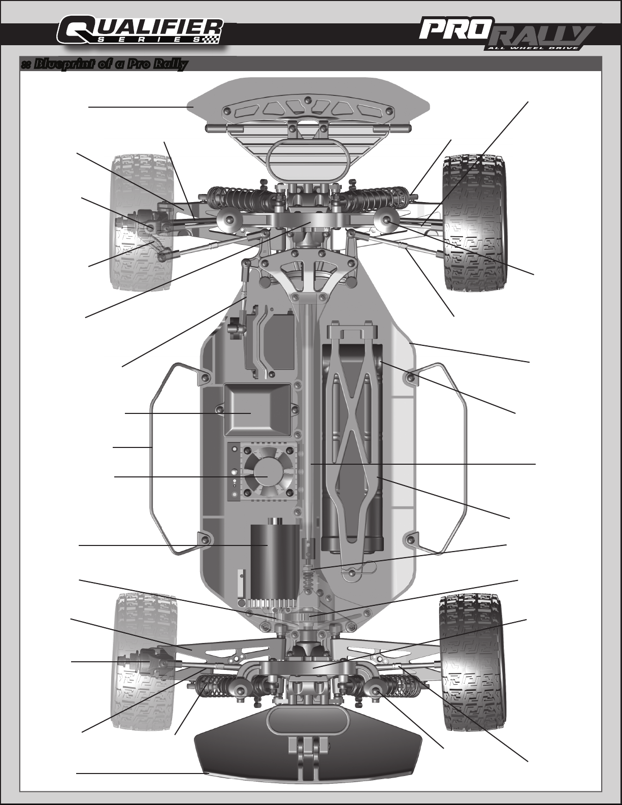
:: Blueprint of a Pro Rally
Front
Bumper
Front
Arm
Caster
Block
Steering
Block
Front
CVA
Turnbuckle
(Front Camber Link)
Front
Shock
Front
Body Mount
Front
Shock Tower
Turnbuckle
(Front Servo Link)
Receiver Box
Nerf Bar
Electronic Speed
Control
Motor
Pinion
Turnbuckle
(Front Steering Link)
Chassis
Battery
w/ Deans®
Plug
Drive
Shaft
Battery Strap
Slipper Clutch
Spur Gear
Rear
Arm
Rear
Hub
Rear
Dogbone
Rear
Diffuser
Rear
Shock
Rear
Shock Tower
Rear
Body Mount
Turnbuckle
(Rear Camber Link)
Page 5
:: Quick Start Guide
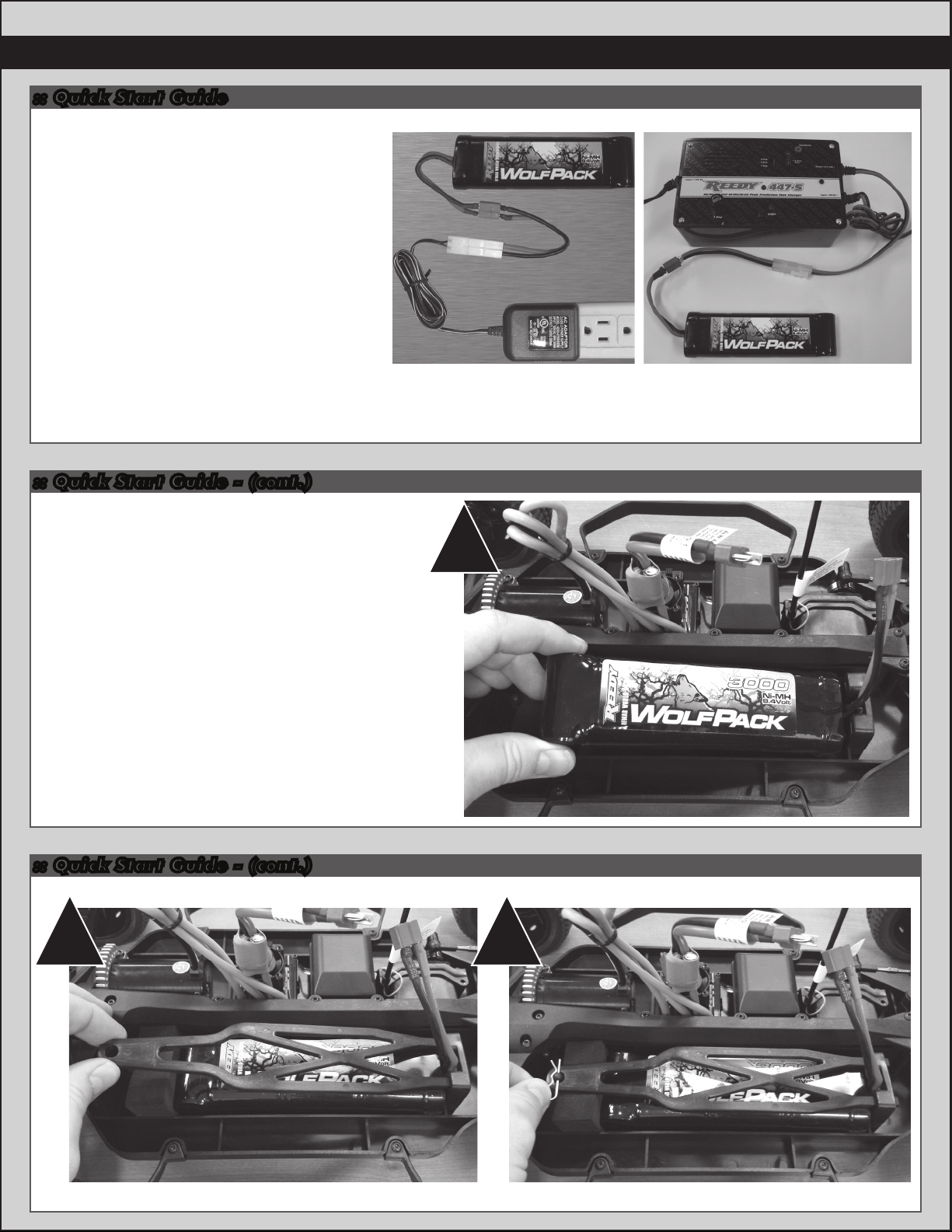
Battery Charging Steps and Safety:
NiMH Wall Charger: (Part #29154 Wall Charger AC 120V 350MaH)
NiMH Quick Charger: (Part #610 Reedy 447-S AC/DC 4-7 Cell Peak Prediction
NiMH/NiCd Charger)
Remove the battery from the vehicle before
charging. Be sure to select the correct
charging mode for the type of battery you
are charging.
NEVER leave the battery unattended while
charging!
5
NiMH: NiMH batteries (nickel-metal hydride)
are high current rechargeable batteries.
If you use a peak detection charger, make sure
it is designed for NiMH batteries!
:: Quick Start Guide - (cont.)
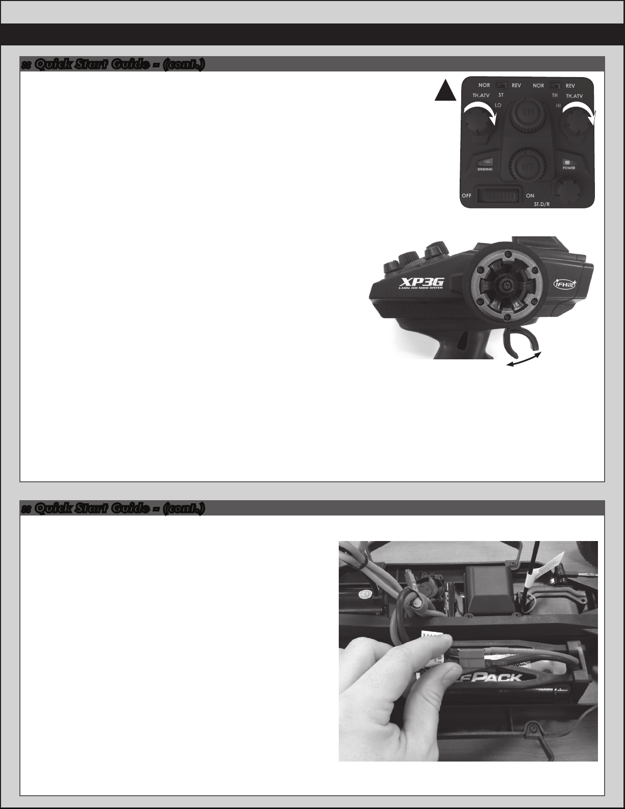
Battery Installation:
1. Install the battery with the battery wires
directed towards the rear of the vehicle.
2. Insert the tabs of the battery strap into
the battery wall.
3. Slide the opposite side of the battery
strap onto the battery post and secure
with a body clip.
You may move the foam pad to either the
front or the rear of the battery compartment
to adjust the weight balance of the vehicle.
Wall Charger Peak Detection
Quick Charger
1
:: Quick Start Guide - (cont.)
2 3
Page 6
6
:: Quick Start Guide - (cont.)
Change the speed control to NiMH or LiPo battery modes.
*NOTE: The Transmitter & ESC come Pre-Programmed!
1) Make sure both TH. ATV (LO & HI) is set on your transmitter
all the way to the right or at 100% before you start.
2) Turn on the transmitter.
3) Pull trigger to full throttle and hold it.
4) Turn on the speed control. You will hear six beeps (bibibibibibi)
and see six flashing green lights.
5) Release trigger back to neutral. You will hear two sets of two
beeps (bibi-bibi) and see four flashing green lights.
6) Push trigger to full brakes/reverse. You will hear two sets of
two beeps (bibi-bibi) and see four flashing green lights.
7) Release trigger back to the neutral position.
You will see a red static light.
Wait a few seconds and you will hear audio tones.
8) For NiMH Battery you will hear 1 tone, a pause, then 1 tone
pull and release trigger to select this mode. You will hear two
sets of two beeps (bibi-bibi) and see four flashing green lights.
Now the speed control is in NiMH (nickel metal mode).
If this is your desired setting, turn of f your speed control and radio!
If not, do not select this mode and continue to step #9.
9) For Lipo Battery you will hear 1 tone, a pause, then 2 tones
pull and release trigger. You will hear two sets of two beeps
(bibi-bibi) and see four flashing green lights.
Now the speed control is in LiPo mode (lithium polymer mode)
Throttle set to Neutral when turning on the radio !
1
Pull for Throttle
Push for
Brake
Neutral
10) If this is your desired setting, turn off your speed
control and radio! If you would like to change the
Drag Brake, Throttle Profile, and Run Mode, see page 17
for the rest of the Speed Control setup sequence.
:: Quick Start Guide - (cont.)
Battery Notes and Tip:
Plug the battery in as shown. Unplug battery when not in use!
There are two types of batteries you can use with this vehicle.
NiMH (nickel-metal hydride) and LiPo (lithium polymer).
LiPo: LiPo batteries (lithium polymer) are high current
rechargeable batteries. LiPo batteries offer extended run time
and peak performance over NiMH batteries. They require a
peak detection charger designed specifically for LiPo batteries.
LiPo/LiFe Charger: (Part # 604 - Reedy 526-S AC/DC 2S-6S
Cell LiPo/LiFe Balance Charger)
These batteries require specal care and handling.
LiPo batteries are recommended for advanced users only!
ALWAY S charge a LiPo battery in LiPo mode.
CAUTION! If using a LiPo battery, you need to change the speed
control settings to LiPo mode (see page 17 for instructions).
If using a 3S LiPo battery, you must use a smaller pinion gear
(use part #91164 13T Pinion). This will give you the correct gear
ratio for the extra power the 3S LiPo
battery will deliver.
Page 7
:: Quick Start Guide - (cont.)
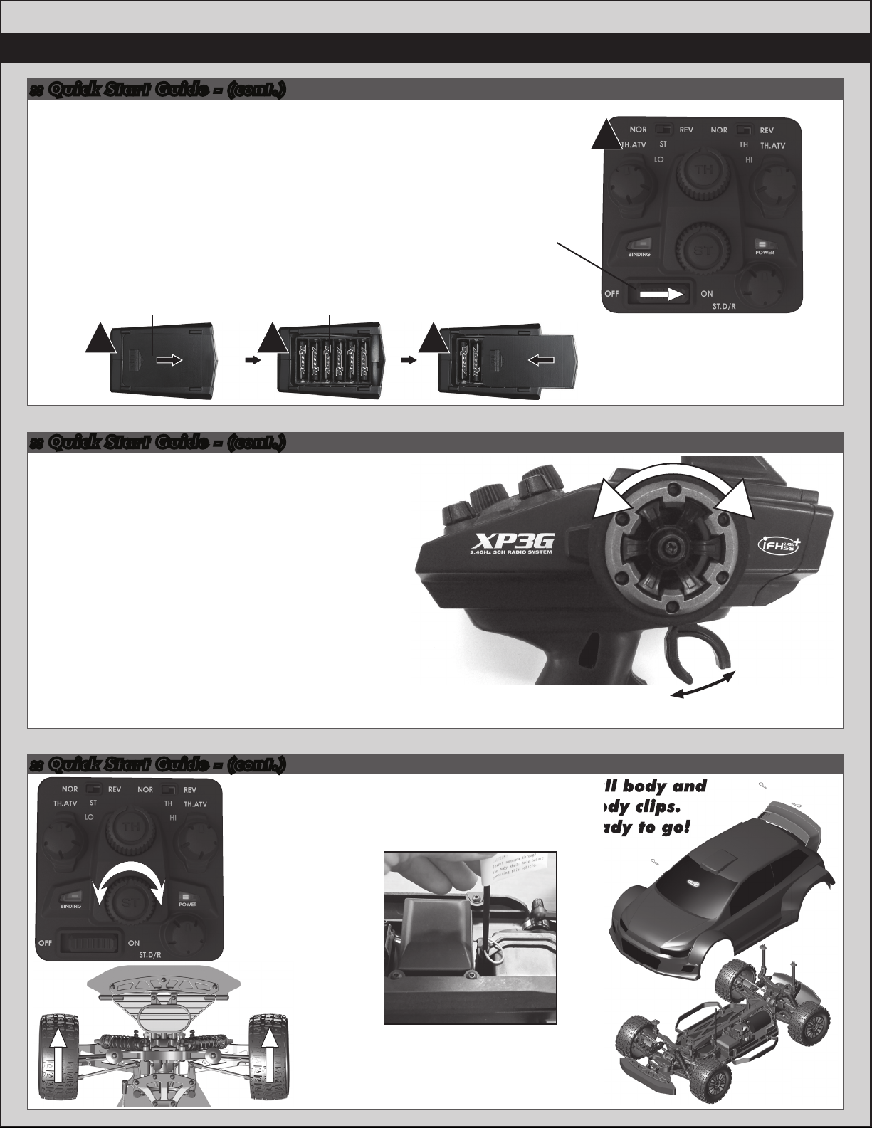
Radio System Tuning and Controls:
7
RULE: Transmitter on First/Vehicle on Second, Vehicle
off First/ Transmitter off Last!
1) Slide the battery cover in the direction shown to
remove cover.
2) Install six (6) alkaline or rechargeable AA size
batteries into the battery holder.
3) Slide the battery cover back into place making
sure it is completely closed and secore.
4) Turn the power ON. If the power indicator LED
fails to light, check the batteries for insufficient
contact or incorrect polarity.
While pressing this part Battery cell (x6)
1 2 3
Battery cover
:: Quick Start Guide - (cont.)
Radio System Tuning and Controls:
DO NOT hold the trigger when turning on the radio.
If using optional battery for transmitter, be sure to plug
it in correctly. Plugging in a battery backwards can
cause damage.
4
On/Off Switch
RightLeft
Refer to Radio owners manual for more in-depth
instructions on radio operation and functions.
:: Quick Start Guide - (cont.)
Adjust steering
trim so front
wheels point
straight.
Push for
Brake
Pull for Throttle
Neutral
Throttle set to Neutral when turning on the radio !
Install body and
body clips.
Ready to go!
Install antenna wire
through antenna tube,
then install antenna
tube as shown.
Page 8
8
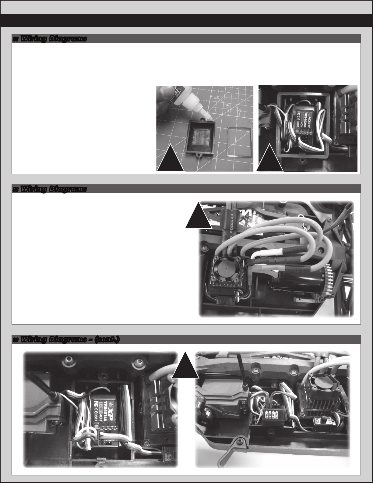
:: Wiring Diagrams
Receiver Box Gasket Maintenance:
1. Apply a small amount of “hobby grade” glue (not included) to the top edge of
the receiver box in order to hold the receiver box gasket in place.
Do the same for the receiver box lid. Make sure not to get glue on the side
of the gaskets that will make contact with each other!
Wait untill the glue has completely dried
before moving on to the next step!
2. Once the receiver box gasket is installed,
you can then plug your servo and speed
control into your receiver. You can also
run your receiver’s antenna wire into the
antenna tube. Once this is done, you can
now install the radio box lid. The gasket
attached to the receiver box and the
gasket attached to the receiver box lid
will squeeze against the servo, speed
control, and antenna wires.
1 2
:: Wiring Diagrams
Motor and Receiver Wiring:
1. If motor runs in reverse when you apply throttle,
unplug any two of the motor wires and switch them.
2. Your Receiver has multiple channel ports for plugs.
Channel 1 - you should always plug your steering
servo into this channel port.
Channel 2 - you should always plug your speed
control (ESC) into this channel port.
Channel 3 - Used for optional equipment such as
fans, lights, ect...
Batt - Used for optional receiver battery pack.
Not used in this model.
Negative black wires on steering servo and speed control
plugs should face the outside edge of receiver where
channel markers are located.
:: Wiring Diagrams - (cont.)
1
2
Page 9
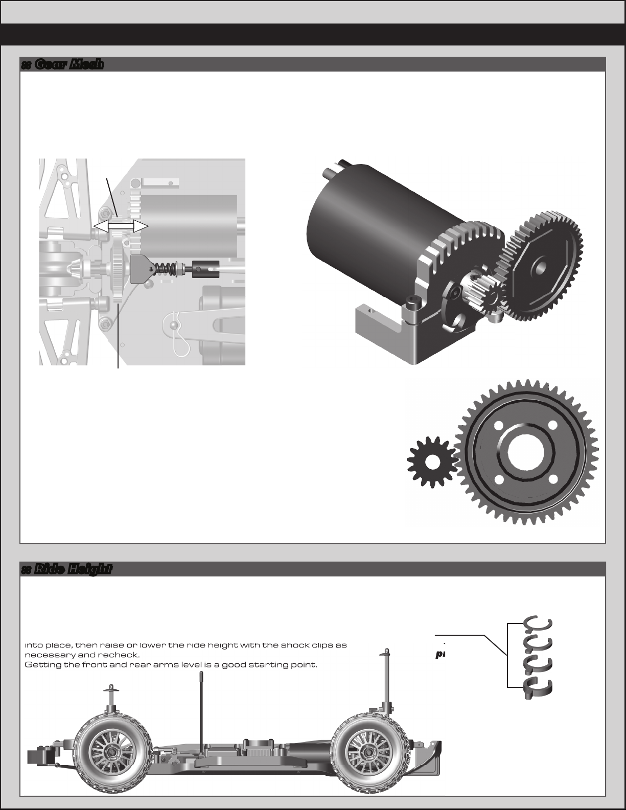
:: Gear Mesh
Shock
pre-load
into place, then raise or lower the ride height with the shock clips as
necessary and recheck.
Getting the front and rear arms level is a good starting point.
Gear Mesh:
To correctly set your gear mesh, follow the steps below:
1. Remove the Chassis Brace. Loosen the set screw on the motor’s pinion gear. Slide the pinion on the motor shaft
until the gear face of the pinion is entirely aligned with the gear face of the spur gear (see diagram). Tighten the set
screw while ensuring it is aligned with the flat face on the motor shaft.
Pinion
9
Spur Gear
2. Loosen the motor clamp screw until the motor is able to move freely.
Rotate the motor as far as it can go towards the spur gear, ensuring that the
teeth of the pinion and the spur gear are interlocking. Slide the motor back
(approximately 0.5 mm), and tighten the motor clamp screw. Proper gear
mesh has been achieved when the teeth are meshing closely, but the gears
still have a small amount of clearance between them. If you hold one gear, you
should be able to rock the other gear back and forth a small amount. If there
is no clearance, your gear mesh is too tight and you should readjust the motor
again.
:: Ride Height
Adjusting Ride Height:
Ride height is adjusted by adding and /or removing shock pre-load clips to the front
and rear shocks. Stock setting is approximately 35mm front and rear. Check the
ride height with the FT Ride Height Gauge (#1449) by lifting up the entire vehicle
about 8-12 inches off the bench and drop it. Af ter the suspension “settles”
into place, then raise or lower the ride height with the shock clips as
necessary and recheck.
Getting the front and rear arms level is a good starting point.
Pinion
pre-load
Spur Gear
Front shock: 4mm
Rear shock: 4mm
7149
Shock
clips
1mm
2mm
4mm
6mm
Page 10

10
:: Camber / Toe
Front Camber Angle:
A good starting camber setting is –2 degrees (where the top of the tires lean inwards). Positive camber, where the top
of the tire is leaning out, is typically not recommended.
Front Toe-In:
Zero degree toe-in (tires pointing straight forward) is a good starting setting. You can increase steering into corners
by adding 1-2 degrees of toe-out (front of tires point slightly outward). Front toe - in is not a typical tuning adjustment
used.
Rear Camber:
A good starting camber setting is –2 degrees. Use #1719 camber gauge (not included) to set your camber. Adding a
small amount of positive camber, where the top of the tire is leaning out, will tend to improve straight-line acceleration on
loose tracks.
:: Slipper Adjustments
Adjusting the Slipper:
To adjust the slipper, use a 7mm open end
wrench or some pliers to grip the slipper
nut. Roll the vehicle forward to tighten
the slipper, roll the vehicle
backwards to loosen the slipper.
TIP: for easier slipper adjustment,
remove the chassis brace, battery brace,
and battery as shown!
3.5mm-4.0mm of
thread showing
Page 11

:: Bumper Adjustments
Bumper Adjustments:
To run your vehicle in off-road conditions (big jumps), it is recommended that you switch
your front and rear bumpers to their off-road positions. This allows for greater ground
clearance. The body should be trimmed level with the bottom edge of the bumper.
On-Road
Front Bumper Adjustments:
Off-Road
:: Bumper Adjustments - (cont.) :: Body Post Adjustments
Rear Bumper Adjustment: Body Post Trimming:
11
On-Road
Remove and flip
brace over.
:: Spur Gear Access
!
Note screw
orientation
Off-Road
!
Note screw
orientation
When adjusting body post height, you may
need to trim the body posts to clear the
rear shocks. Check for clearance by
compressing the suspension arm and look
for interferencs.
Trim
Page 12

12
Rear Shock Tower Removal:
the shocks and camber turnbuckles
The dogbones will come out when the
you replace them when re-installing
the rear shock tower!
:: Spur Gear Access - (cont.)
Rear Shock Tower Removal:
Loosen the ball studs highlighted in
order to remove the shock tower with
the shocks and camber turnbuckles
attached as one completepiece.
The dogbones will come out when the
shock tower is removed. Make sure
you replace them when re-installing
the rear shock tower!
:: Spur Gear Access - (cont.)
:: Spur Gear Access - (cont.)
Slide center bulkhead
cap forward to remove
slipper assembly!
Page 13

:: Spur Gear Access - (cont.)
Slipper Pads
Spur Gear Maintenance:
When accessing your spur gear, check for wear on the
teeth of the gear. The teeth should be nice and sharp.
Also, check the slipper pads for wear.
Replace if necessary.
A good starting point for slipper setup is to have 3.5 to
4.0mm of thread showing on the shaft.
3.5mm-4.0mm of
thread showing
:: Front Diff Access - (cont.)
13
Slipper Pads
:: Front Diff Access - (cont.)
Front Shock Tower Removal:
Loosen the ball studs highlighted in
order to remove the shock tower
with the shocks and camber
turnbuckles attached as one
complete piece.
Make sure you re-install the CVA
bones into the diff outdrives when
re-installing the front shock tower!
Page 14

14
:: Front Diff Access - (cont.)
:: Diff Maintenance
Differential Maintenance:
:: Shock Maintenance
Stock Diff
Fluid Setting:
Front:
black grease
Rear:
black grease
Diff
fluid
Once you have removed the Dif f gear, you can now drain
the existing diff fluid from the differential.
Check the diff gasket for wear or damage.
Replace if necessary
Fill the diff to the top of the cross pin with your choice of
black grease #6588 or diff fluids.
Front Diff:
Thicker oil will get less low speed steering and better acceleration out of turns.
Rear Diff:
Thicker oil will rotate less in the turns and accelerate
straight on power. Thinner oil will give more low speed
traction (optional diff fluids listed on page 19).
Page 15

:: Shock Maintenance - (cont.)
:: Shock Maintenance - (cont.)
35wt
Shock fluid
Stock Shock
Fluid Setting:
Front: 35wt
Rear: 35wt
15
Bladder Installation
A B C
As you install the shock cap with the bladder, it will force
out any extra fluid. If you install the cap with the shaft
fully extended, you are running FULL REBOUND.This
means the shaft will fully rebound when compressed.
To run less rebound, unthread the cap 1-2 turns and
compress the shaft to the desired position and
re-tighten the cap with the shaf t compressed.
Start with no rebound.
Stock Shock
Limiter Setting:
Front: 4 limiters
Rear: 8 limiters
External
Shock Limiter:
8mm
:: Shock Maintenance - (cont.)
Step 5Step 3-4Step 1-2
Step 6-8
Shock Maintenance:
If you need to only refill your shocks with oil, follow the steps
above only then move to the shock bleeding steps.
If your shocks leak from the bottom shock cap, follow all
shock maintenance sections.
Replace the inner O-Ring in the bottom cap, then begin the
shock oil filling and bleeding process.
Shock Bleeding Steps:
1. Pull shock shaft down.
2. Fill shock body 3/4 full with silicone
shock fluid.
3. Slowly move the shock shaf t up and
down to remove air from under the
piston.
4. Wait for bubbles to come to surface.
5. Fill shock body to top with silicone
shock fluid.
6. Place a drop of oil in the cap and on
cap threads.
7. Install cap and tighten completely.
8. Unscrew the cap 3/4 turns and tilt
the shock at a slight angle.
9. Slowly compress shaf t all the way to
bleed excess silicone shock fluid and
air. You should see bubbles coming
out from under the cap. (use rag
around shock to catch excess fluid).
10. With the shaft compressed, tighten
the cap and re-check for pressure at
the top of the stroke. If there is still
pressure, repeat steps 3-9.
Check for
pressure
Slow
Some residual
shock fluid may
appear from your
first few runs
around the shock
cap as a result of
bleeding.
Slow
Step 9-10
!
Page 16

16
:: Motor Manual
BRUSHLESS
550-SL
MOTOR
Introduction
Congratulations on your purchase of the Reedy 550-SL
Brushless Motor. The latest brushless motor technology
along with the design and engineering experience that is
responsible for 29 World Championship titles has been
incorporated into its design.
Due to its sensorless design, the Reedy 550-SL Brushless
Motor operates powerfully and efficiently without
complicated sensor harnesses. This motor is perfectly
suited for use with ESCs that are designed to operate
sensorless brushless motors.
Features
• Oversized Precision Ball Bearings
• High-Torque 4-Pole Rotor
• Hardened 5mm Steel Shaft
• Triple-Insulated Windings
• Sensorless Operation
• 3.5mm Connectors
• Completely Rebuildable
Because no single motor works best in all vehicles and in all
conditions, two models are available to suit any application.
Be sure to visit www.reedypower.com for the latest
application and gearing charts for each model and to view
a complete list of spare and option parts.
Please read the following before installing and using
your new motor.
Precautions and Warnings
• Please read the instructions before installing and
operating your motor.
• Avoid over gearing by monitoring motor temperature.
Operating temperatures should not exceed 80C (175F)
• Be sure to use the proper size motor mounting screws.
• Do not over-tighten the motor mounting screws.
• Do not use a Schottky diode with this motor.
Installation and Maintenance
• Your motor should be installed using 3mm screws with a
length (generally 6mm or less) that does not allow the
screw to extend into the motor more than 5mm.
Otherwise, the screw can damage the motor’s internal
components.
• Do not over-tighten the motor mounting screws.
Doing so may strip the mounting hole threads.
• Connect the three leads exiting the motor to the three
motor leads from your Electronic Speed Control (ESC).
If the motor runs backwards when giving it forward
throttle, reverse any two motor leads. The motor will
now turn in the desired direction.
• To clean your motor, lightly brush dirt away on a regular
basis paying particularly close attention to the areas
around the ball bearings. DO NOT spray cleaners or
solvents into the motor.
Caution
When switching to a higher voltage battery from a lower
one (11.1V to 7.4V, for example), a change in gear
ratio or a lower kV motor might be necessary. Otherwise,
the motor or ESC may overheat and sustain permanent
damage. Please visit www.reedypower.com for the latest
gear ratio suggestions for your particular motor and
vehicle.
Safety Precautions
This product is a sophisticated hobby product and not a
toy. It must be operated with caution and common sense
and requires some basic mechanical ability. Failure to
operate this product in a safe and responsible manner
could result in injury or damage to the product or property.
This product is not intended to be used by children without
direct adult supervision. It is essential to read and follow
all instructions and warning found in this manual prior to
installation, set up, and use in order for the product to
operate properly and to avoid damage or injury.
Specifications
Model
Item No.
Cells
RPM/Volt
Diameter
Length
Weight
Shaft Diameter
Max. Efficiency Current
Max. Surge Current
Internal Resistance
Warranty
Your motor is warranted to the original purchaser for 30
days from the date of purchase against defects in material and workmanship. Motors that have been mishandled,
abused, used incorrectly, used for an application other
than intended or damaged by the user are not covered
under warranty.
Associated Electrics Inc. is not liable for any loss or
damage, whether direct or indirect, incidental or
consequential, or from any special situation, arising from
the use, misuse, or abuse of this product.
550-SL 3500kV
924
2-3 LiPo, 4-8 NiMH
3500
36mm
55mm
210g/7.4oz
5.0mm
10~45A
55A/60s
550-SL 4000kV
925
2-3 LiPo, 4-8 NiMH
4000
36mm
55mm
200g/7.1oz
5.0mm
10~50A
60A/60s
Page 17

:: ESC Manual
17
Page 18

18
5407
25231
25231
:: Shocks
4187
5407
7143
7144
7145
7146
7147
7148
7149
7150
7151
7152
7725
25231
Nylon Spacer .030
Red Silicone O-Ring
Rear Shock Kit
Front Shock Kit
Shock Bodies, FR/RR
w/ Top & Bottom Caps, & Hat Bushings
Shock Bladders
Shock Shafts, FR/RR w/Rod Ends (4)
Pistons, 1.2, 1.3, 1.4 w/E-Clips
Shock Clips w/Spring Retainer (4), Spring
Cup (4), & Rod Ends (4)
Shock Springs, Soft FR/RR
Shock Springs, Medium FR/RR - Kit
Shock Springs, Hard FR/RR
Fuel Tubing 3 feet
E-Clip, 2.5mm
7145
7146
25231
7148
25231
7147
12
8
2
2
2ea
4
2ea
4ea
4ea
2ea
2ea
2ea
1
20
7149
7149
:: Servo Saver/Mount
6338
7137
7138
7163
7167
25202
Antenna Tube w/Cap
Servo Mount
Servo Saver
Ball Stud, (3 short/7 long) Set
Tap Screw BHPS
M3 x 10mm FHCS
6338
6338
7137
7167
1
1
1
1
10
20
7138
7163
7138
7145
5407
7145
7145
:: Shock Fluid
5420
5421
5422
5423
5424
5425
5426
5427
5428
5429
5430
5431
5432
5433
5434
5435
5436
5437
5438
10 Weight Silicone Shock Fluid
20 Weight Silicone Shock Fluid
30 Weight Silicone Shock Fluid
40 Weight Silicone Shock Fluid
22.5 Weight Silicone Shock Fluid
80 Weight Silicone Shock Fluid
27.5 Weight Silicone Shock Fluid
15 Weight Silicone Shock Fluid
25 Weight Silicone Shock Fluid
35 Weight Silicone Shock Fluid
45 Weight Silicone Shock Fluid
55 Weight Silicone Shock Fluid
32.5 Weight Silicone Shock Fluid
37.5 Weight Silicone Shock Fluid
42.5 Weight Silicone Shock Fluid
50 Weight Silicone Shock Fluid
60 Weight Silicone Shock Fluid
70 Weight Silicone Shock Fluid
47.5 Weight Silicone Shock Fluid
7725
4187
7147
-OR-
7149
2oz.
2oz.
2oz.
2oz.
2oz.
2oz.
2oz.
2oz.
2oz.
2oz.
2oz.
2oz.
2oz.
2oz.
2oz.
2oz.
2oz.
2oz.
2oz.
7151
7149
7167
25202
:: Steering
7139
7163
31400
7163
Bellcrank Assembly, Set
Ball Stud, (3 short/7 long) Set
Bearing, 5 x 8mm
31400
7139
31400
7139
25202
1
1
2
7139
7139
31400
7163
7163
7139
7139
31400
7139
Page 19

:: Front and Rear Gear Differential
7133
7134
7189
7732
25607
31350
Diff - Complete
Diff Outdrive w/Set Screw
Diff Rebuild Kit
M4 x 4mm Set Screw
Bearing, 8 x 14 x 4
M2.5 x 10mm FHCS
7189
31350
19
1
2
1
6
4
6
25607
7134
7134
-OR-
7732
25607
7134
7134
-OR-
7732
:: Lubes & Adhesives / Decals / Misc.
1105
1596
1597
5450
5451
5452
5453
5454
5455
5456
5457
5458
5459
6588
6591
6636
6727
FT Green Slime Shock Lube
FT Locking Adhesive
FT Tire Adhesive, Medium
Silicone Diff Fluid 1000cst
Silicone Diff Fluid 2000cst
Silicone Diff Fluid 3000cst
Silicone Diff Fluid 5000cst
Silicone Diff Fluid 7000cst
Silicone Diff Fluid 10000cst
Silicone Diff Fluid 20000cst
Silicone Diff Fluid 30000cst
Silicone Diff Fluid 60000cst
Silicone Diff Fluid 100000cst
Black Grease - 4cc
S.Diff Lube - 4cc
Silicone Grease - 4cc
Servo Tape
1
1
1
1
1
1
1
1
1
1
1
1
1
1
1
1
2
7189
:: Battery Strap
6332
7115
89209
89455
Body Clips
Battery Strap w/Wall & Post, Set
M3 x 18mm FHCS
M3 x 22mm FHCS
6
1
10
10
6332
7115
7115
716
717
3816
3820
3834
9787
Reedy 2009 Sticker Set
Reedy Powered Logo Decal
American Bumper Sticker
AE Logo Decal Sheet
AE Blue Embossed Logo Sticker
FT Chassis Protective Sheet
1
1
1
1
2
1
1596
89455
7115
89209
Page 20

20
:: Front Gearbox
2308
5407
7116
7117
7124
7134
7135
7155
7158
7163
7166
7732
25202
25211
25215
25231
25710
89202
M3x18mm BHCS
Red Silicone O-Ring
ProLite Chassis Braces
Gearboxes FR/RR, Top & Bottom
Front Input Shaft, Set
Diff Outdrive, w/ set screw
Drive Pinion
Arm Mounts, A & D Plates
Hinge Pins (inner & outer), Bushings
(0, 1, 2, & arm washers) Set
Ball Stud, (3 short/7 long) Set
4mm E-Clip
M4x4mm Set Screw
M3x10mm FHCS
M3x10mm BHCS
M3 Locknut, black
E-Clip, 2.5mm
Bearing, 5 x 11 x 4
M3x12mm BHCS
6
8
1
1ea
1
2
1
1ea
1
1
10
6
20
20
20
20
2
10
7158
7158
7158
89202
7163
7117
25211
2308
25211
7116
89202
7163
7134
5407
7158
7155
25202
:: Front Suspension
7128
7129
7130
7140
7141
7157
7158
7163
7165
7168
25211
25616
91027
91148
CVA Axle, Front
CVA Bone, Front
CVA Coupler w/Pin
Steering & Caster Blocks
Steering Block Bushing
Front Arms w/arm washers (4) &
M2 x 4mm BHPS screws (2), Set
Hinge Pins (inner & outer), Bushings
(0, 1, 2, & arm washers) Set
Ball Stud, (3 short/7 long) Set
Washer, 6 x 12mm
M2 x 4mm BHPS, Flanged
M3 x 10mm BHCS
Bearing, 10 x 15 x 4
4x4 Wheel Hex w/Hardware
M4 Locknut, w/Flange & Knurl
7158
7158
2
2
2
2ea
4
1
1
1
10
10
20
2
4
8
7158
7158
7163
25211
7158
25211
7140
7141
7158
7129
7130
25710
7135
25231
7117
7130
7128
7124
7163
7166
25215
7134
-OR-
7732
7157
7163
7168
7158
7140
7165
25616
91027
91148
Page 21

:: Rear Gearbox
7117
7155
7158
7163
25202
25215
89202
Gearboxes FR/RR, Top & Bottom
Arm Mounts, A & D Plates
Hinge Pins (inner & outer), Bushings
(0, 1, 2, & arm washers) Set
Ball Stud, (3 short/7 long) Set
M3 x 10mm FHCS
M3 Locknut, Black
M3 x 12mm BHCS
21
1ea
1ea
1
89202
1
20
20
10
25202
:: Rear Suspension
7131
7132
7142
7156
7163
7158
7165
7168
25616
91027
91148
Dogbone (RR)
Axle/Dogbone
Hub Carrier
Rear Arms w/arm washers (4) &
M2 x 4mm BHPS screws (2), Set
Ball Stud, (3 short/7 long) Set
Hinge Pins (inner & outer), Bushings
(0, 1, 2, & arm washers) Set
Washer, 6 x 12mm
M2 x 4mm BHPS, Flanged
Bearing, 10 x 15 x 4
4x4 Wheel Hex w/Hardware
M4 Locknut, w/Flange & Knurl
7155
7158
7158
2
2ea
2
1
1
1
10
10
2
4
8
7158
7158
7158
7158
7131
7158
7158
7158
7158
7163
7117
7117
89202
7163
25215
7163
7156
7132
25616
7163
7168
7158
7142
91027
25616
7165
91148
Page 22

22
:: Front Bumper
2308
7171
7188
25201
89202
89204
M3 x 18mm BHCS
Pro Rally Foam Bumper
Pro Rally Bumper Set
M3 x 8mm FHCS
M3 x 12mm BHCS
M3 x 24mm BHCS
6
1
1
20
10
10
2308
7188
89202
2308
89202
:: Rear Bumper
2308
7172
25201
91478
M3 x 18mm BHCS
Pro Rally Diffuser Set
M3 x 8mm FHCS
M3 x 30mm BHCS
6
1
20
6
89204
7171
-OR-
7188
7188
89202
7188
7188
25201
89204
91478
7172
7172
2308
25201
Page 23

:: Front Shock Tower :: Rear Shock Tower
7153
7154
7173
7184
25187
25215
89205
89218
Shock Bushings
Shock Tower, Front & Rear
Pro Rally Body Mount Set
M2 x 16mm SHCS
M3 x 14mm BHCS
M3 Locknut, Black
M3 x 26mm BHCS
Washer, 3 x 8mm
1ea
10
20
20
10
10
7153
4
7154
7173
1
7184
25187
25215
89205
89218
Shock Bushings
Shock Tower, Front & Rear
Pro Rally Body Mount Set
M2 x 16mm SHCS
M3 x 14mm BHCS
M3 Locknut, Black
M3 x 26mm BHCS
Washer, 3 x 8mm
23
4
1ea
1
10
20
20
10
10
89218
25215
7184
25187
7173
7153
89218
7173
89218
7184
25187
89205
7154
7173
89205
89218
89205
89218
7173
89205
7154
25187
7173
7184
89218
25187
7173
7184
89218
7153
89218
25215
25215
:: Motor Mount :: Turnbuckles
4675
7136
7164
25202
25620
91158
7136
25202
M2.5 x 6mm FHCS
Motor Mount Set
Washer, 3 x 6 x 0.5mm
M3 x 10mm FHCS
M3 x 10mm SHCS
M3 x 4mm BHCS
25620
6
1
10
20
20
10
4675
7136
7136
91158
7164
7159
7160
ProLite Turnbuckle Set w/ Ball Cups
ProLite Ball Cups
7160
7160
7160
Servo
Link
7159
Front
Camber
7159
Steering
Link
7159
Rear
Camber
1
14
7160
7160
7160
7160
7159
7160
Page 24

24
:: Chassis
2308
7112
7113
7114
7116
25187
25202
25211
25215
31532
89202
89203
M3x18mm BHCS
ProLite Chassis
Nerf Bars
Receiver Box w/Gaskets
ProLite Chassis Braces
M3x14mm BHCS
M3x10mm FHCS
M3x10mm BHCS
M3 Locknut, black
M3x8mm BHCS
M3x12mm BHCS
M3x16mm BHCS
6
1
2
1
1
20
20
20
20
6
10
10
25187
7113
7116
89202
25215
89203
89202
25211
25187
31532
7116
7116
2308
25211
31532
31532
7114
7114
7114
25215
7112
25202
25202
89202
25215
89202
7113
25215
Page 25

:: Slipper, Spur Gear, Pinion, and Drive Shaft
2
5407
7122
7123
7124
7125
7126
7127
7135
7732
25225
25231
25710
91162
91163
91164
91165
91166
Red Silicone O-Ring
Spur Gear 32P, 47T
Slipper Hardware, Kit
Slipper Shaft
Slipper Pads
Slipper Hubs
Drive Shaft w/ O-Rings
Drive Pinion
M4x4mm Set Screw
M3x3mm Set Screw
E-Clip, 2.5mm
Bearing, 5x11x4
Pinion Gear, 11T 32P (5mm shaft)
Pinion Gear, 12T 32P (5mm shaft)
Pinion Gear, 13T 32P (5mm shaft)
Pinion Gear, 14T 32P (5mm shaft) Kit
Pinion Gear, 15T 32P (5mm shaft)
25710
7123
7126
7123
8
1
1
1
2
2
1
1
6
20
20
2
1
1
1
1
1
7125
7122
7126
7125
25710
7124
25
25231
7135
7732
91165
25225
5407
:: Wheels / Tires
7174
7175
7176
7177
7178
89413
91101
91102
91103
Pro Rally Wheel, Black
Pro Rally Wheel, White
Pro Rally Tire
Pro Rally Wheel and Tire, Black - Kit
Pro Rally Wheel and Tire, White
Molded Tire Insert
KMC Hex Wheels, Black (Kit)
KMC Hex Wheels, Silver
KMC Hex Wheels, Chrome
7127
7123
2
2
2
2
2
2
2
2
2
7174
89413
7176
Page 26

26
:: Body / Wing / Decals
6332
7179
7180
7181
7182
7187
89202
Body Clips
Pro Rally Wing Set
Pro Rally Body, Clear (wing not included)
Pro Rally Rockstar Body, Black
Pro Rally Rockstar Body, White
Pro Rally Decal Sheet
M3x12mm BHCS
7179
89202
7179
89202 89202
7179
7179
89202
:: Factory Team and Option Parts
6
1
1
1
1
1
10
1734
1735
1736
1737
7183
9787
31286
31550
91160
91171
FT Body Clips, Metallic Blue, 4 Long, 6 Short
FT Body Clips, Metallic Blue, Long
FT Body Clips, Metallic Blue, Short
FT Body Scissors
Sway Bar Set - Pro lite / Pro Rally
FT Chassis Protective Sheet
FT Ballstud Washer, Aluminum (2mm and 1mm)
FT M3 Locknut, Blue Aluminum
Body Clip, 1.3mm Thick
4x4 Aluminum Wheel Hexes
:: XP Electronics
29107
29134
29139
29142
29144
29166
29167
29168
29209
29210
29211
29212
29214
29215
29216
29253
XP DS1903/S1903 Metal Gear Set
XP DS1903MG Digital Servo
XP SC900-BL Brushless ESC
XP ESC Fan Option
XP SC1200-BL Brushless ESC
XP DS1313 Digital Servo
XP DS1015 Digital Servo
XP DS1510MG Digital Servo
Gear Set, DS1313
Gear Set, DS1015
Servo Case , DS1313/DS1015
Accessory Pack, DS1313/DS1015
TRS403-SSi 2.4GHz 4Ch Receiver
XP2G 2.4GHz Radio System
XP3G 2.4GHz Radio System
XP DS1510 Metal Gear Set
1
4
6
1
1
1
4ea
6
10
4
1
1
1
1
1
1
1
1
1
1
1
1
1
1
1
1
6332
7180
6332
8920289202
:: Reedy Motors and ESC’s
6332
909
924
925
927
928
Replacement Rotor 550-SL
550-SL Brushless Motor 3500kV
550-SL Brushless Motor 4000kV
Reedy 550-SL 3500kV/XP SC1200-BL ESC Combo
Reedy 550-SL 4000kV/XP SC1200-BL ESC Combo
1
1
1
1
1
Page 27

27
:: Reedy Batteries
302
724
725
730
731
732
734
735
AA Alkaline 1.5V (4)
Wolfpack 3000mAh 8.4V w/T-Plug connector
Wolfpack 3600mAh 8.4V w/T-Plug connector
Wolfpack LiPo 3000mAh 7.4V 25C w/T-Plug
Wolfpack LiPo 3300mAh 7.4V 35C w/T-Plug
Wolfpack LiPo 3400mAh 7.4V 35C w/T-Plug
Wolfpack LiPo 6500mAh 7.4V 25C w/T-Plug
Wolfpack LiPo 3900mAh 11.1V 35C w/T-Plug
:: Reedy Accessories
604
609
610
660
661
663
664
974
975
526-S AC/DC 2S-6S LiPo/LiFe Charger
TAM to DEANS® charge adapter
447-S AC/DC NiMH Peak Charger
3.5mm plugs (3M, 3F)
3.5mm plugs (10F)
3.5mm plugs (10M)
3.5mm plugs (30M)
540-SL/550-SL Steel Bearing Set
540-SL/550-SL Ceramic Bearing Set
:: 1/18 Kits and RTR’s
1
20103
1
20121
1
1
1
1
1
1
RC18B2 - RC18T2 Team Kit
SC18 RTR Brushless (ready-to-run)
:: 1/12, 1/10 Kits and RTR’s
4020
RC12R5.2 Factory Team Kit
6002
RC10 Worlds Car Kit
7025
7028C
7030C
1
1
1
1
1
1
30101
1
30109
1
90001
1
90003
90010
RC10T4.2 Factory Team Kit
SC10 Pro Comp RTR (ready-to-run) Combo
7030
SC10 KMC Wheels Race Truck RTR (ready-to-run)
SC10 KMC Wheels RTR (ready-to-run) Combo
7038
SC10.2 Factory Team Kit
7039
RC10T4.2 RS RTR 2.4GHz Brushless (ready-to-run)
7046
SC10 RS RTR, Lucas Oil (ready-to-run)
7049
SC10 RS RTR, Rockstar/Makita (ready-to-run)
7050
SC10 RS RTR, Hart and Huntington (ready-to-run)
7051
SC10 RS RTR, Lucas Slick Mist® Body
7054
SC10 RS RTR, Toyota Racing/TRD
7055
SC10 RS RTR, Monster Energy Toyota
7093
SC10GT RTR (ready-to-run)
9042
RC10B4.2 RS RTR 2.4GHz Brushless (ready-to-run)
9050
SC10B RS RTR (ready-to-run)
9062
RC10B44.2 Factory Team 4WD Buggy Kit
TC4 Club Racer 4WD Touring Car Race Roller
RC10TC6.2 Factory Team 4WD Touring Car Kit
RC10B5 Team Kit
RC10B5M Team Kit
SC10 4x4 Factory Team Kit
1
1
1
1
1
1
1
1
1
1
1
1
1
1
1
1
1
1
1
1
1
1
1
1
1
:: Qualifier Series Vehicles
7052
7070
20111
20119
20510
30112
Pro Lite 4x4 RTR, 1/10 Scale (ready-to-run)
Pro Rally RTR, 1/10 Scale (ready-to-run)
Rival Mini Monster Truck 1/18 Scale (ready-to-run)
APEX Mini Touring Car 1/18 Scale (ready-to-run)
RIVAL Electric Monster Truck RTR, 1/8 Scale
(ready-to-run)
APEX Touring V-Type, 1/10 Scale (ready-to-run)
:: 1/8 Kits and RTR’s
1
20501
1
20502
1
20503
1
1
20504
1
80906
80907
80908
80909
80912
80933
80934
MGT 4.60 SE RTR (ready-to-run)
MGT 8.0 Nitro RTR (ready-to-run)
Limited Edition MGT 4.60 Nitro RTR, w/flag body
(ready-to-run)
Limited Edition MGT 8.0 Nitro RTR, w/flag body
(ready-to-run)
RC8.2 Nitro Buggy FT Kit
RC8.2e Electric Buggy FT Kit
RC8.2e Electric Buggy RTR (ready-to-run)
RC8.2RS Nitro Buggy RTR (ready-to-run)
RC8T Championship Edition
SC8.2e Short Course Race Truck, Rockstar/Makita
Electric RTR (ready-to-run)
SC8.2e Short Course Race Truck, Slick Mist Electric
RTR (ready-to-run)
1
1
1
1
1
1
1
1
1
1
1
Page 28

:: Hardware - 1:1 Scale View
28
Socket Head (shcs)
2 x 6mm (7186)
2 x 16mm (7184)
3x10mm (25620)
Setscrew
3x3mm (25225)
4x3mm (25223)
4x4mm (7732)
Nuts (lock/plain)
M3 Locknut (25215)
M3 Alum. Locknut, Blue (31550)
M4 Locknut w/Flange & Knurl (91148)
FT M4 Locknuts w/Flange,
Blue (31551)
Flat Head (fhcs)
Ball Bearings
2.5x6mm (4675)
2.5x10mm (31350)
3x8mm (25201)
3x10mm (25202)
3x16mm (89224)
3x18mm (89209)
3x22mm (89455)
5x8mm (31400)
Button Head (bhcs)
2.5x6mm (31520)
3x4mm(91158)
3x8mm (31532)
3x10mm (25211)
3x12mm (89202)
3x14mm (25187)
3x16mm (89203)
3x18mm (2308)
3x26mm (89205)
Button Head (bhps)
Shims and Washers
Nylon Spacer .030 (4187)
3x6mm Washer (7164)
3x8mm Thin Washer
6x12mm Washer (7165)
Pro Lite Diff Shim (7133)
Arm Shim (7158)
(89218)
5x11x4mm, qty 2 (25710)
qty 4 (25618)
10x15x4mm (25616)
2x4mm, flanged (7168)
Tap Screw (7167)
Ballstuds
Ballstud, short (7163)
Ballstud, long (7163)
Page 29

29
:: Apparel
SP31**
SP32**
SP37**
SP38
SP39
SP71**
SP77**
SP78**
SP79**
SP84**
SP86**
SP90**
SP91**
SP92**
SP93**
SP94**
SP95**
SP96**
SP97**
SP98**
SP416
SP417
SP420**
:: Notes
SP421S
SP421L
SP422S
SP422L
SP423S
SP423L
SP424S
SP424L
715
716
110684
27 Time WC T-Shirt, Black (S, M, L, XL, 2XL, 3XL)
Kids AE 2012 T-Shirt, Blue (S, M, L)
Reedy 2012 T-shirt - Black (S, M, L, XL, 2XL, 3XL)
Reedy Trucker Hat
Reedy Patch
Associated Winter Jacket (M, L, XL)
AE 2012 T-Shirt, Blue (S, M, L, XL, 2XL, 3XL)
AE 2012 T-Shirt, White (S, M, L, XL, 2XL, 3XL)
AE 2012 T-Shirt, Black (S, M, L, XL, 2XL, 3XL)
Reedy 3D T-Shirt, Black (S, M, L, XL, 2XL, 3XL)
Reedy Womens 3D T-Shirt, Black (S, M, L, XL)
AE Retro T-Shirt, Blue (S, M, L, XL, 2-5XL)
AE Retro T-Shirt, Black (S, M, L, XL, 2-5XL)
AE Retro T-Shirt, White (S, M, L, XL, 2-5XL)
2013 Worlds T-Shirt, Blue (S, M, L, XL, 2-5XL)
2013 Worlds T-Shirt, Black (S, M, L, XL, 2-5XL)
2013 Worlds Hoodie, Black (S, M, L, XL, 2-3XL)
AE Retro Womens T-Shirt, Pink (S, M, L, XL)
AE Retro Womens T-Shirt, Black (S, M, L, XL)
AE Womens T-Shirt, Black (S, M, L, XL)
Associated Car Carrier Bag, Medium
1/10 FT Motor Bag
AE Pit Gloves (L, XL)
AE 2012 Hat, Black, Flat Bill, S/M
AE 2012 Hat, Black, Flat Bill, L/XL
AE 2012 Hat, Black, Curved Bill, S/M
AE 2012 Hat, Black, Curved Bill, L/XL
AE 2012 Hat, White, Flat Bill, S/M
AE 2012 Hat, White, Flat Bill, L/XL
AE 2012 Hat, White, Curved Bill, S/M
AE 2012 Hat, White, Curved Bill, L/XL
Reedy 2009 Track Banner
Reedy 09’ Decal Set
Team Associated Track Banner
** Use part number plus the desired size when ordering!
:: RePlay Cameras
RP002
RP004
RP021
RP022
RP023
RP024
RP029
RP030
RP032
RP033
RP034
RP036
RP038
RP041
RP042
RP043
RP044
RP045
RP046
RP047
RP048
RP049
RP054
Replay XD720 Complete Camera System
Replay XD1080 Mini Camera System
Replay XD1080 Lens Bezel Kit
Replay XD1080 Clear Lens Cover
Replay XD1080 Lens Bezel & Rear Cap O-Ring
Replay XD Lens Bezel
Replay XD1080 HDMI to Mini-HDMI
Replay XD1080 Mini 8-pin USB Charge Data Cable
USB DC Car Charger 1A Stubby
USB DC Car Charger 500mAh
Micro SDHC USB Reader
3M VHB 4991 Mount Adhesive for SnapTray
3M VHB 5962 Mount Adhesive for SnapTray
Replay XD Suction Cup Arm Mini Clamp
Replay XD Suction Cup Short Arm Base
Replay XD Skateboard Mount
Replay XD VHB SnapTray, Convex
Replay XD VHB SnapTray, Flat
Au Plug for Universal DC Wall Charger
Eu Plug for Universal DC Wall Charger
Uk Plug for Universal DC Wall Charger
Universal USB DC Wall Charger 1A
Replay ReView Field Monitor
1
1
1
1
1
1
1
1
1
1
1
1
1
1
1
1
1
1
1
1
1
1
Pr.
1
1
1
1
1
1
1
1
1
1
1
1
1
1
1
1
1
1
1
1
1
1
1
1
1
1
1
1
1
1
1
1
1
1
:: Tools
1112
1449
1541
1542
1543
1544
1545
1546
1547
1548
1553
1554
1561
1562
1563
1564
1565
1567
1589
1590
1592
1655
1656
1657
1658
1659
1660
1661
1662
1663
1664
1665
1666
1667
1668
1669
1670
1671
1672
1673
1674
1719
1737
3718
3719
3720
3987
6429
6956
7494
7709
Check out the following web sites for all of
releases, setup help, tips, and racing info!
FT 4mm Turnbuckle Wrench
FT Off Road Ride Height Gauge
FT Hex Driver Set, (7 pcs)
FT .050” Silver Hex Driver
FT 1/16” Black Hex Driver
FT 1.5mm Purple Hex Driver
FT 5/64” Blue Hex Driver
FT 3/32” Gold Hex Driver
FT 2.5mm Green Hex Driver
FT 3mm Red Hex Driver
FT Phillips Silver Screwdriver
FT Silver Spring Hook Tool
FT Nut Driver Set, (6 pcs)
FT 3/16” Black Nut Driver
FT 1/4” Red Nut Driver
FT 5.5mm Red Nut Driver
FT 11/32” Green Nut Driver
FT 8mm Gold Nut Driver
FT 5/64” Blue Ball Hex Driver
FT 3/32” Gold Ball Hex Driver
FT Ball Hex Driver Set, (3 pcs)
FT 8-Piece 1/4” Hex Drive Set
FT 1/4” Hex Drive Handle, without tips
FT 1/4” Hex Drive .050” Tip
FT 1/4” Hex Drive 1/16” Tip
FT 1/4” Hex Drive 5/64” - 2.0mm Tip
FT 1/4” Hex Drive 3/32” Tip
FT 1/4” Hex Drive 1.5mm Tip
FT 1/4” Hex Drive 2.5mm Tip
FT 1/4” Hex Drive 3/16” Nut Driver Tip
FT 1/4” Hex Drive 1/4” Nut Driver Tip
FT 1/4” Hex Drive 11/32” Nut Driver Tip
FT 1/4” Hex Drive 5.5mm Nut Driver Tip
FT 1/4” Hex Drive 7.0mm Nut Driver Tip
FT 1/4” Hex Drive 8.0mm Nut Driver Tip
FT 1/4” Hex Drive 5/64” - 2.0mm Ball End Tip
FT 1/4” Hex Drive 3/32” Ball End Tip
FT 1/4” Hex Drive Standard Screwdriver Tip
FT 1/4” Hex Drive Phillips Screwdriver Tip
FT 1/4” Hex Drive 2.5mm Ball End Tip
FT 1/4” 5 Piece Power Tool Tips Set (5/64-2.0mm,
1.5mm, 2.5mm, 5/64”- 2.0mm ball, 2.5mm ball)
FT Camber + Track Width Tool
FT Body Scissors
12 Inch Nylon Wire Ties
6 Inch Nylon Wire Ties
8 Inch Nylon Wire Ties
FT Droop Gauge
Shock Building Tool
Molded Tools, Set
V2 Stamped Multi-Tool
4 Inch Nylon Wire Ties
Associated Electrics, Inc.
26021 Commercentre Drive
Lake Forest, CA 92630-8853 USA
http://www.TeamAssociated.com
http://www.RC10.com
http://twitter/Team Associated
http://bit.ly/AEonFacebook
call: (949) 544-7500
fax: (949) 544-7501
our electric kits, current products, new
1
1
1
1
1
1
1
1
1
1
1
1
1
1
1
1
1
1
1
1
1
1
1
1
1
1
1
1
1
1
1
1
1
1
1
1
1
1
1
1
1
1
1
12
12
12
1
1
1
1
12
www.TeamAssociated.com. - www.RC10.com
Page 30

:: Trouble Shooting
Description
Problem
30
Solution
No Power
No Throttle
No Steering
Throttle
Steering
Battery is discharged...........
Battery not plugged in.........
No light on speed control....
Receiver LED remains red.
Motor not plugged in............
Speed control out of ............
adjustment.
Motor failure............................
Servo not plugged in.............
Locked up steering linkage.
Servo failure.............................
Goes backwards when you
pull the trigger, or forward
when pushing brakes /
reverse.
Goes right when turning......
the wheel left (or left when
turned right.)
Charge battery.
Plug in battery.
Reset speed control using
your instruction manual.
Re-bind transmitter to the receiver.
Plug in motor.
Reset speed control using your
instruction manual.
Replace motor.
Plug servo in.
Free up steering linkage.
Replace servo.
Switch any two motor wires.
Check throttle reversing switches
on transmitter. Reset speed
control.
Check steering reversing switches
on transmitter.
Vehicle is
glitching
Reverse
Vehicle dies
or slows
Vehicle has a problem on.....
power.
No reverse or brakes...........
Speed control overheats....
Motor overheats...................
Gear mesh set too tight......
LiPo mode engages...............
Check for loose wires or check for
or dead radio batteries.
Radio interference.
Check that reverse mode has not
been turned off. Refer to speed
control instructions. Reset speed
control, or send in for repair.
Let speed control cool off. Check
gear, gear mesh, or bind in driveline.
Let motor cool and check
recommended gearing for motor
type.
Reset gear mesh (see instruction
manual).
LiPo mode on the ESC has
engaged, recharge your batteries.
(If running NiMH battery, turn off
LiPo mode)
 Loading...