

Page 1
Page 2
2
:: Introduction
Thank you for purchasing this Team Associated product. This assembly manual contains instructions and tips for building and
maintaining your new RC10 B44.3. Please take a moment to read through this manual to help familiarize yourself with these
steps.
We are continually changing and improving our designs; therefore, actual parts may appear slightly different than in the
illustrations. New parts will be noted on supplementary sheets located in the appropriate parts bags. Check each bag for these
sheets before you start to build.
:: KIT Features
The RC10B44 has created a winning legacy with three I.F.M.A.R. World Championships, four R.O.A.R. National titles, and
countless regional wins to its credit! Since winning the 2013 I.F.M.A.R. World Championships, the designers behind the doors of
Area 51 set out to further improve the B44 and take it to an even higher level of performance.
Enter the RC10B44.3 Factory Team Kit, the latest evolution of Team Associated’s 1:10 4WD electric off road competition buggy.
The most significant changes are found on the new hard-anodized aluminum chassis, which helps lower the center of gravity to
improve handling and durability. The chassis has been designed to have symmetrical torsional flex to improve handling
consistency — the new floating motor mount, floating servo mount, and chassis machining help to provide the desired flex
symmetry.
Power and traction have continued to improve, so the B44.3’s drivetrain has been built up and refined to keep up with the
demand of today’s high-traction off-road tracks. A set of four precision CVA’s transfer the power from the gear differentials via
ball bearings throughout the car.
Now the B44.3 is even more adaptable to multiple racing conditions with the adjustable weight bias feature. Weight bias can be
significantly altered by using either the front motor configuration with a saddle pack or the rear motor configuration with a shorty
pack. The B44.3 is also backwards compatible with the previous generation VTS slipper clutch (not included) and ball differentials
(not included), making the B44.3 extremely versatile and adaptable to any track condition.
2
1
1
2
Factory Team V2 12mm big bore shocks have improved smoothness, improving suspension travel and increasing overall traction.
Lastly, the B44.3 comes with the latest JConcepts Finnisher X-Flow body and AE 6.5” high downforce wing.
The RC10B44.3 has been given all of the design advantages that only a winning pedigree like Team Associated can provide.
If you are ready to take your 1:10 4WD off-road program up to the next level, the B44.3 is ready to take you there!
Features in the B44.3 Factory Team:
• Hard anodized aluminum chassis and 7075-T6 floating motor mount allows for front or rear motor configurations
• New molded battery trays accommodate 2S saddle or shorty battery pack configurations and feature a quick-change strap with
• locking thumb knobs
• New front and rear carbon-fiber top decks and floating servo mount improves symmetrical chassis flex
• Front and rear gear differentials have machined steel ring, pinion, and planetary gears
• Center gear differential has independent fluid cap for quick and easy fluid or gear changes
• JConcepts Finnisher X-flow body
• Factory Team 0° 7075-T6 aluminum rear hubs with oversize outer bearing
• Factory Team V2 12mm “Big Bore” threaded aluminum shocks with 3mm shock shafts, molded caps with bleed screws, and
updated O-rings for improved smoothness
• Full CVAs and ball bearing drivetrain
• Factory Team 12mm blue aluminum rear clamping hexes and 12mm hex rear wheels
• Factory Team blue titanium turnbuckles, aluminum servo mounts, aluminum shock pivot balls and rear anti-roll bar included
:: Other Helpful Items
• Silicone Shock Fluid (Refer to catalog for complete listings) • Silicone Diff Fluid (Refer to catalog for complete listings)
• Body Scissors (AE Part # 1737) • Reamer / Hole Punch • Wire Cutters • Hobby Knife
• FT Hex Wrenches (AE Part # 1655) • Needle Nose Pliers • Thread Lock (AE Part #1596)
• Soldering Iron • Calipers or a Precision Ruler • Green Slime shock lube (AE Part # 1105)
Associated Electrics, Inc.
26021 Commercentre Dr.
Lake Forest, CA 92630
http://www.TeamAssociated.com · http://www.RC10.com · http://twitter.com/Team_Associated · http://bit.ly/AEonFacebook
Customer Service
Tel: 949.544.7500
Fax: 949.544.7501
Page 3
3
:: Hardware - 1:1 Scale View
Cap Head (shcs)
(motor mounting screws)
Ball Bearings
Steering Bearing (9746)
4-40x5/16 (6932)
(aluminum ,4145)
4-40x3/8 (6924)
(aluminum ,6860)
4-40x7/16 (7874)
(aluminum, 7873)
4-40x1/2 (6925)
4-40x7/8 (7738)
3x6mm (6515)
3/16x5/16 (6906)
3/16x3/8 (3977)
3/16x1/2 RS (7935)
(for optional
slipper assembly)
3/8x5/8” RS (3976)
Flat Head (fhcs)
Nuts (lock/plain)
4-40 Aluminum Locknut (4449)
4-40 Plastic Nut (6472)
5-40 Nylon Locknut (6222)
8-32 LP Steel Locknut (6953)
8-32 Steel Locknut (6952)
Clips
2.5x10mm (31350)
4-40x5/16 (7673)
4-40x3/8 (6292)
4-40x7/16 (9765)
4-40x5/8 (6915)
E-clip 1/8 (6299)
Button Head (bhcs)
2.5x10mm (31522)
3x6mm (31531)
2-56x1/8 (9645)
2-56x5/16 (4334)
4-40x1/4 (6288)
4-40x3/8 (6917)
4-40x7/16 (2221)
4-40x3/4 (7413)
Shims and Washers
.030 Ballstud Washer (9630)
.030 Nylon Spacer (4187)
Servo Mount Washer (7337)
#4 Washer (6936)
Input Shaft Shim - Black (3911)
Top Hat Bushings
Small Top Hat Bushing (3874)
Large Top Hat Bushing (9647)
Notes:
Ballstuds
Silver .20 Short (6276)
Silver .30 Long (6277)
Black .30 Short (3983)
3/16 Axle Shim - Silver (7368)
Outdrive Shim (3911)
Page 4
4
:: Table of Contents
1....................Cover
15 - 16........Front Suspension Build (Bag K)
2....................Introduction
3....................1:1 Hardware “Fold Out”
4....................Table of Contents
5 - 6..............Front /Center/Rear
Differential Build (Bag A-AA)
7 - 8..............CVA Build (Bag B-BB)
8....................Front/Rear Gearbox Build
(Bag C)
8 - 9..............Steering and Center Battery
Brace Build / Install
(Bag D)
10.................Front End Build (Bag E)
11.................Rear End Build (Bag F)
11 - 12.........Center Bulhead Mounts Install
(Bag G-GG)
16 - 17........Rear Suspension Build
(Bag L-LL)
18 - 19........Shock Build/Install (Bag M-MM)
19 - 20........Battery Cradle/Strap Build
(Bag N-NN)
20 - 21........Servo Build (Bag O-OO)
21.................Servo Chart
22.................Electronics Install
22 - 23.......Body, Wheel, Tires Install
(Bag P)
24 - 25........Tuning Tips
26.................Notes
27 - 35.......Catalog
36.................Setup Sheet “Kit Setup”
13.................Front Top Deck Build (Bag H)
13 - 14........Rear Top Deck Build (Bag I)
14.................Turnbuckles Build (Bag J)
:: Notes
This symbol indicates a special
note or instruction in the manual.
!
This symbol indicates a Racers Tip.
37.................Setup Sheet “Blank”
38.................Back Cover
There is a 1:1 hardware foldout page in the
front of the manual. To check the size of a part,
line up your hardare with the correct drawing
until you find the exact size. Each part in the
foldout has a number assigned to it for ordering
replacement parts.
Associated Electrics, Inc.
26021 Commercentre Dr.
Lake Forest, CA 92630
http://www.TeamAssociated.com · http://www.RC10.com · http://twitter.com/Team_Associated · http://bit.ly/AEonFacebook
Customer Service
Tel: 949.544.7500
Fax: 949.544.7501
Page 5
8/14
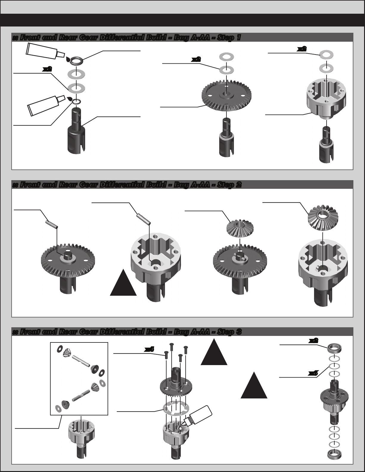
:: Front and Rear Gear Differential Build - Bag A-AA - Step 1
#6588
black grease
9888
0.5mm
gear diff
shim
x2
9937
O-ring
(4.7 x 1.42)
9888
0.5mm
gear diff
shim
x2
9888
0.5mm
gear diff
shim
5
x2
#6588
black grease
9937
O-ring
(3.6 x 0.7)
9937
B44.3 gear
diff outdrives
Build x2
9934
B44.3 ring
gear
:: Front and Rear Gear Differential Build - Bag A-AA - Step 2
9937
9937
Pin,
2x9mm
Pin,
2x9mm
91463
Gear diff
sun gear
9935
B44.3
diff case
(front/rear)
91463
Gear diff
sun gear
!
NOTE: Use full
depth slot to
slide pin in!
:: Front and Rear Gear Differential Build - Bag A-AA - Step 3
x4
!
Tighten the
screws evenly in a
crossing order!
Check for smooth diff action,
adjust shimming as needed.
5k diff
fluid #5453
Fill to top of cross pins after
checking gear mesh.
Moving shims from inside to
outside will loosen the diff.
Moving shims from outside to
inside will tighten the diff.
NOTE: not all shims may be
needed to get the desired feel.
91463
Gear diff
planet gears,
shims, and
pins
31350
2.5x10mm
fhcs
9935
B44.3
diff gasket
!
6903
3/8 x 5/8,
bearing
3911
Shim set
x2
x6
Page 6
6
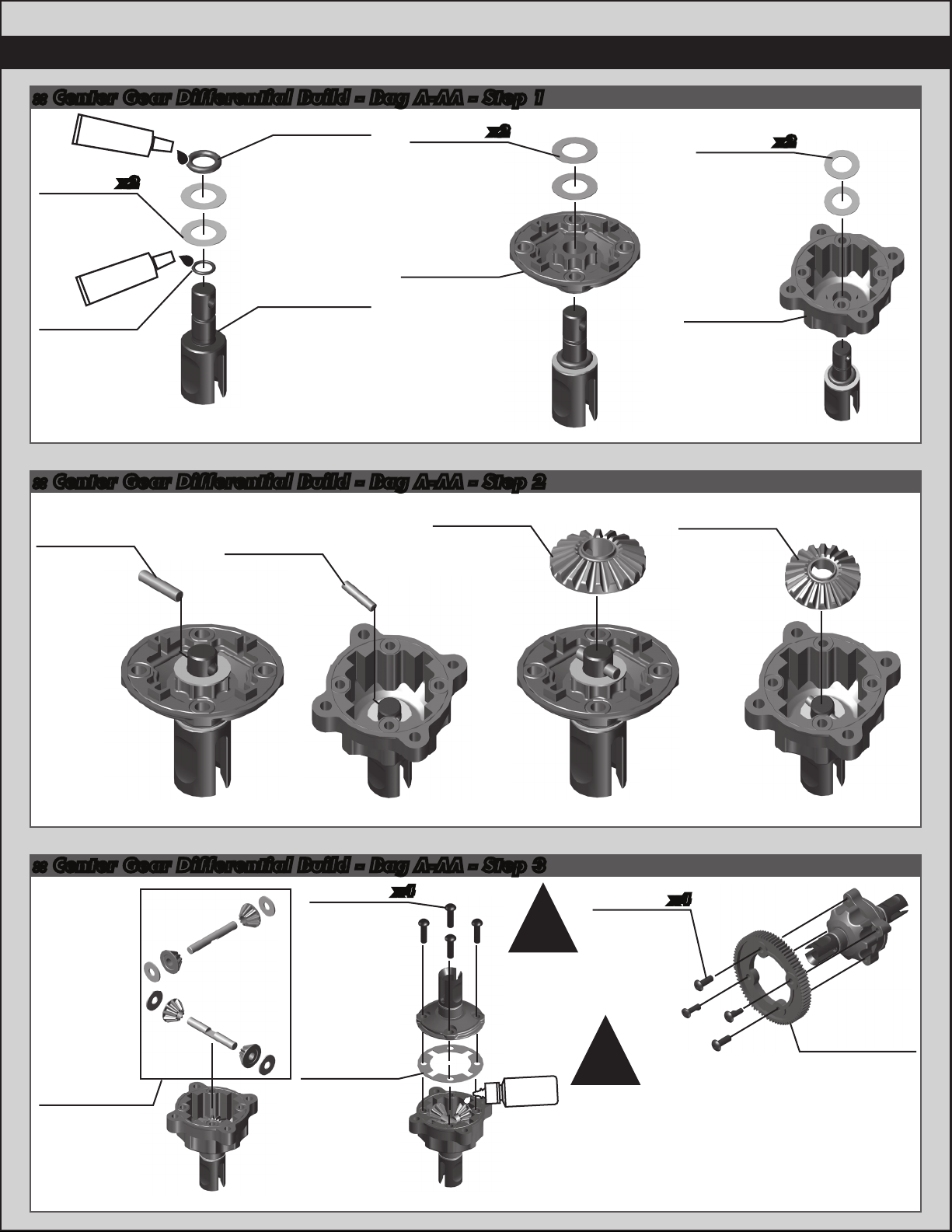
:: Center Gear Differential Build - Bag A-AA - Step 1
#6588
black grease
9888
0.5mm
gear diff
shim
x2
9937
O-ring
(4.7 x 1.42)
9888
0.5mm
gear diff
shim
x2
9888
0.5mm
gear diff
shim
x2
#6588
black grease
9937
O-ring
(3.6 x 0.7)
9937
B44.3 gear
diff outdrives
Build x2
9936
B44.3
center diff
case
:: Center Gear Differential Build - Bag A-AA - Step 2
91463
9937
Pin,
2x9mm
9937
Pin,
2x9mm
Gear diff
sun gear
9936
B44.3
center diff
case
91463
Gear diff
sun gear
:: Center Gear Differential Build - Bag A-AA - Step 3
x4
!
Tighten the
screws evenly in a
crossing order!
60k diff
fluid #5458
91463
Gear diff
planet gears,
shims, and
pins
31522
2.5x10mm
bhcs
9936
B44.3
diff gasket
6919
4-40x5/16
!
Fill to top of cross pins after checking gear
mesh. Check for smooth diff action, adjust
shimming as needed. Moving shims from inside
to outside will loosen the diff. Moving shims
from outside to inside will tighten the diff.
NOTE: not all shims may be needed to get the
x4
bhcs
9938
B44.3 81T
spur, gear diff
desired feel.
Page 7
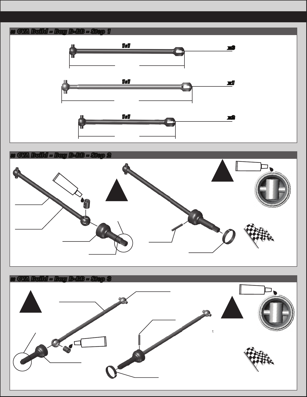
:: CVA Build - Bag B-BB - Step 1
to be opposite of
7
Front and
Front Center
CVA Bone:
Rear Center
CVA Bone:
Rear
CVA Bone:
:: CVA Build - Bag B-BB - Step 2
Front and Rear CVA Build:
#6588
black grease
9747
CVA bone
(front)
9754
CVA bone
(rear)
Build x4 (2 front, 2 rear)
9748
CVA axle
(front)
NOTE: the front
and rear CVA
axles have threads
on the ends.
9755
CVA axle
(rear)
1:1
81.4mm
1:1
92.2mm
1:1
68.7mm
!
7381
CVA pin
9747
CVA bone
9596
CVA bone
9754
CVA bone
Align the gap in
the pin retainer
to be opposite of
the CVA pin.
7996
CVA pin
retainer
x3
x1
x2
#1597
ca glue
!
Try using only 1 drop of CA glue
1 drop!
Racer’s Tip:
to secure the pin retainer!
:: CVA Build - Bag B-BB - Step 3
Front and Rear Center CVA Build:
9747
!
NOTE: the front
and rear center
CVA axles have
flats on the ends.
Build x2 (1 front, 1 rear)
CVA bone
(center, front)
black grease
9942
B44.3 input
shaft
(gear diff)
#6588
9596
CVA bone
(center, rear)
7381
CVA pin
7996
CVA pin
retainer
#1597
ca glue
1 drop!
!
Align the gap in
the pin retainer
to be opposite of
the CVA pin.
Try using only 1 drop of CA glue
to secure the pin retainer!
Racer’s Tip:
Page 8
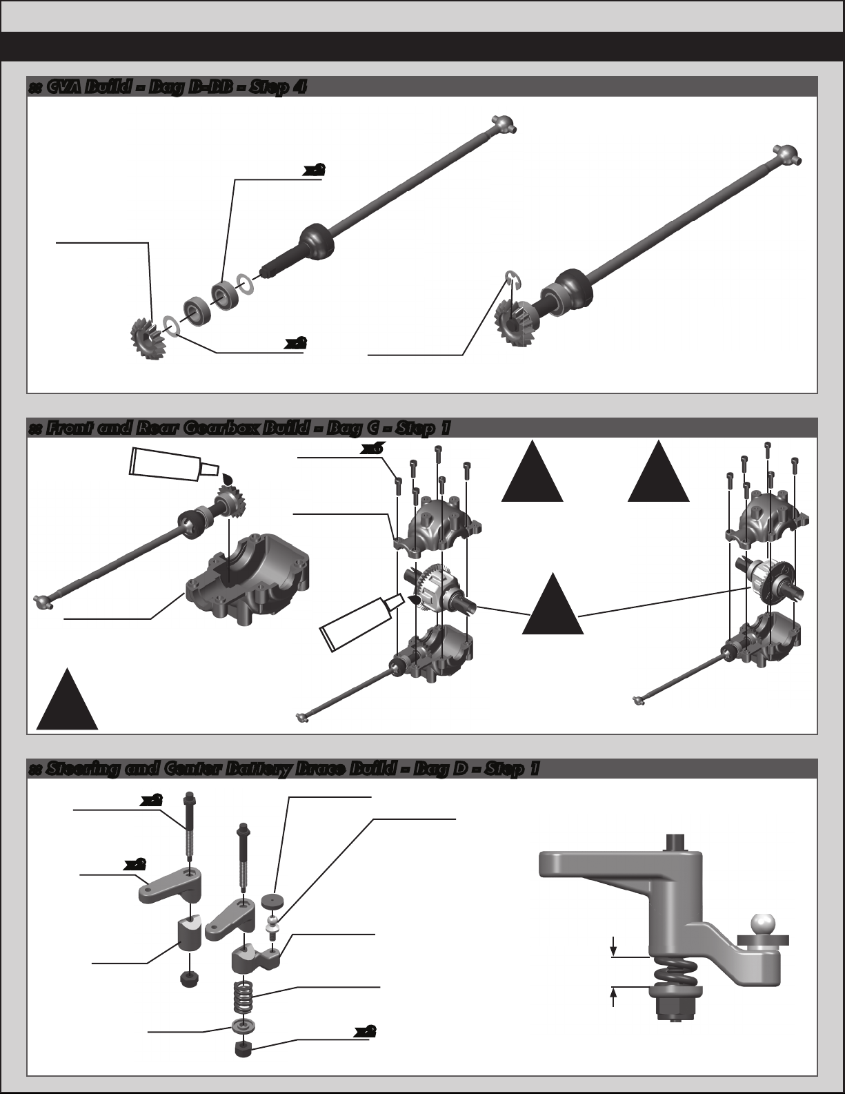
8
:: CVA Build - Bag B-BB - Step 4
Front and Rear Center CVA Build:
x2
x2
6299
E-clip, 1/8
6906
3/16x3/8
bearing
9933
B44.3 input
pinion gear
3911
Drivetrain
shim
:: Front and Rear Gearbox Build - Bag C - Step 1
#6588
black grease
1 drop!
6924
4-40x3/8
shcs
Upper
transmission
x6
9733
case
! !
NOTE: Check
gear mesh,
ensure it has a
small amount
of backlash.
NOTE:
Optional ball diff
kits are available,
AE #9735.
1 drop!
9733
Lower
transmission
case
NOTE: Adjust diff
shimming side to side
until diff spins free
!
with minimal backlash.
#6588
black grease
orientation of
the gear diffs will be
flipped when in shorty
pack configuration.
Build two Gearboxes
(Saddle Pack Configutation):
NOTE: The
:: Steering and Center Battery Brace Build - Bag D - Step 1
9744
Steering
post
9743
Servo
saver
upper
x2
9743
Steering
v-spacer
x2
9743
Spring
retainer
6272
Dust cover
foam
9743
Servo saver
lower
9744
Servo saver
spring
9744
5-40
locknut
x2
6276
Ballstud, .20
silver, short
!
Build two Gearboxes
(Shorty Pack Configutation):
1mm
Page 9
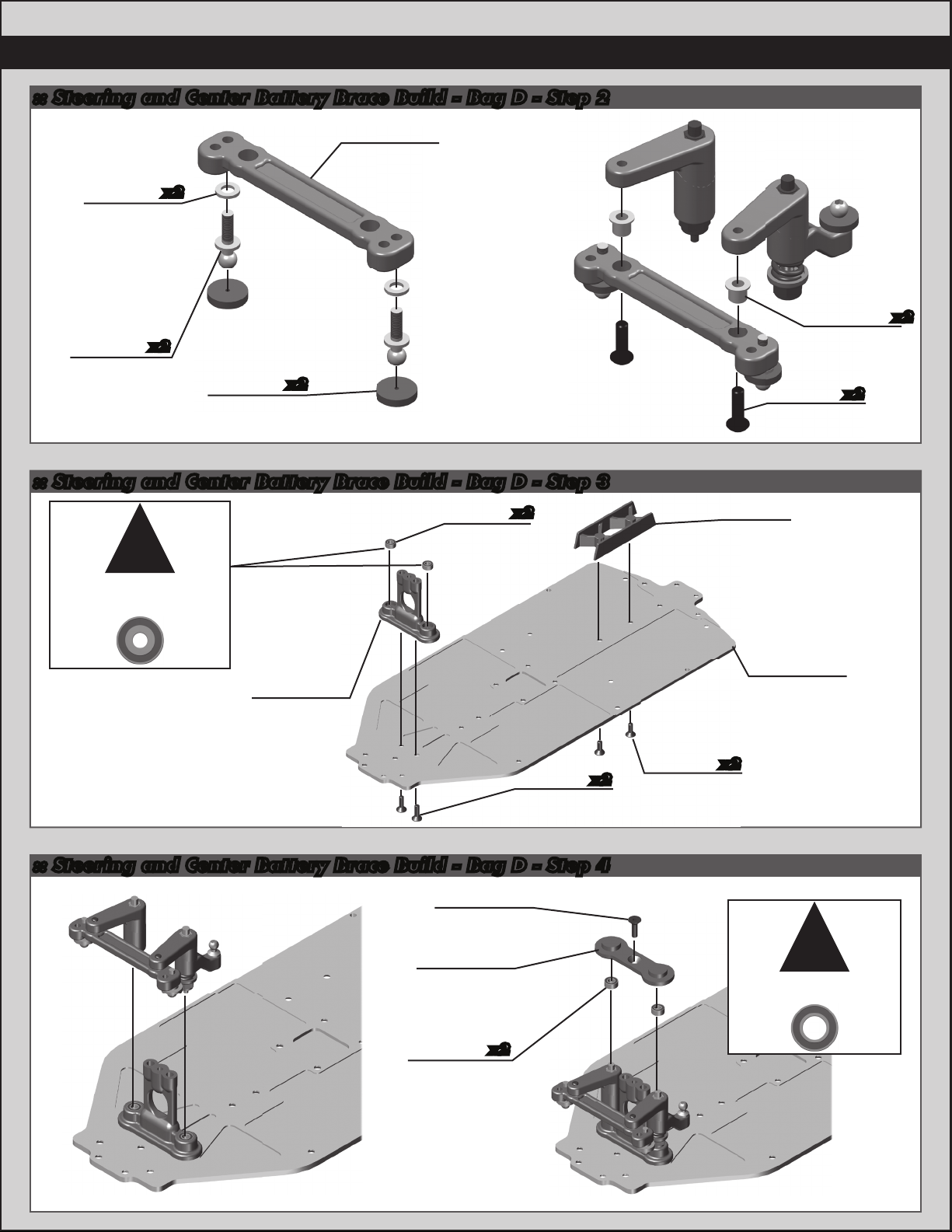
:: Steering and Center Battery Brace Build - Bag D - Step 2
9743
Steering
rack
9630
.030
washer
x2
9
6277
Ballstud, .30
silver, long
x2
6272
Foam dust
cover
x2
:: Steering and Center Battery Brace Build - Bag D - Step 3
!
Use the small hole
bearings!
9746
Steering
bearing
9743
Steering
retainer
column
set
x2
6292
4-40x3/8
fhcs
x2
7673
4-40x5/16
x2
fhcs
4-40x3/8
9905
Center
battery
cradle
B44.3
aluminum
chassis
3874
Black carrier
bushing
6917
bhcs
9946
x2
x2
:: Steering and Center Battery Brace Build - Bag D - Step 4
6292
4-40x3/8
fhcs
9743
Steering
retianer top
9746
Steering
bearing
x2
set
!
Use the large hole
bearings!
Page 10
10
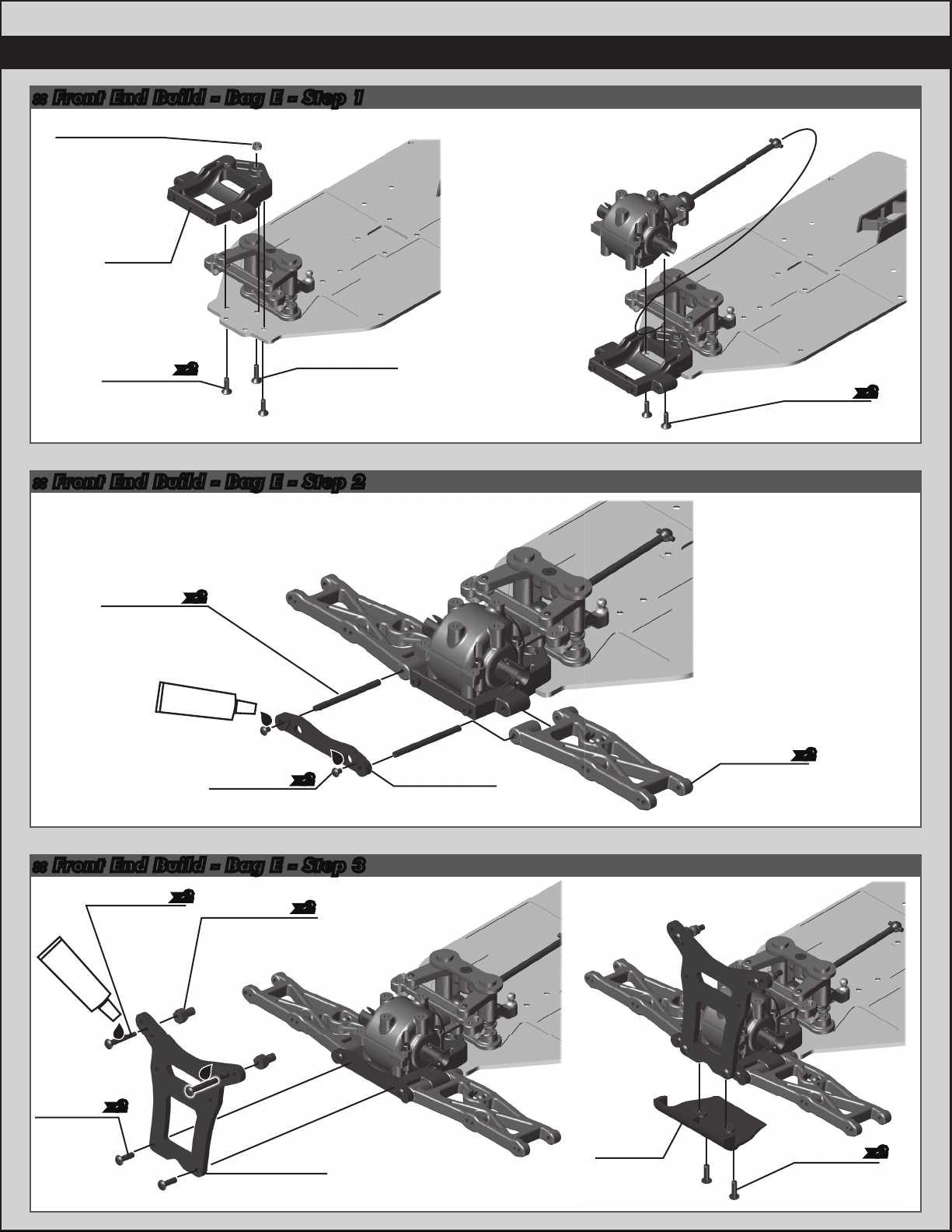
:: Front End Build - Bag E - Step 1
4449
4-40x3/16
aluminum
locknut
9713
Front
bulkhead
Front/Center CVA Gearbox Install:
6292
4-40x3/8
x2
9765
4-40x7/16
fhcs
fhcs
:: Front End Build - Bag E - Step 2
9716
Front inner
hinge pin
x2
#1596
thread lock
9645
2-56x1/8
bhcs
x2
9717
Front hinge
pin brace
4-40x3/8
9715
Front arm
6292
fhcs
x2
x2
:: Front End Build - Bag E - Step 3
4-40x3/4
#1596
thread lock
6917
4-40x3/8
bhcs
7413
bhcs
x2
x2
9945
V2 aluminum
shock bushing
Front shock
x2
9903
tower
9718
Front
bumper
6917
4-40x3/8
bhcs
x2
Page 11
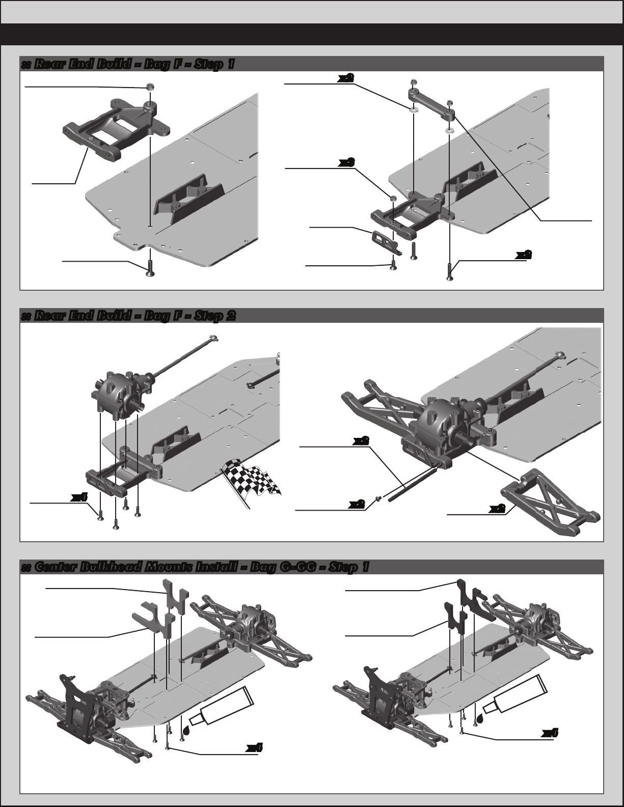
:: Rear End Build - Bag F - Step 1
4449
4-40x3/16
aluminum
locknut
6936
x2
#4 washer
11
9726
Rear
chassis
plate
9765
4-40x7/16
fhcs
:: Rear End Build - Bag F - Step 2
Rear/Center CVA Gearbox Install:
4449
x3
4-40x3/16
aluminum
locknut
9718
Rear
bumper
7673
4-40x5/16
fhcs
9716
Rear inner
hinge pin
x2
6915
4-40x5/8
fhcs
9726
Rear arm
mount
x2
6292
4-40x3/8
fhcs
x4
Racers Tip:
Ensure arms can
move freely.
9645
2-56x1/8
bhcs
x2
9764
Rear
arm
:: Center Bulkhead Mounts Install - Bag G-GG - Step 1
9931
B44.3 center
bulkhead
9932
B44.3
motor mount
#1596
thread lock
6292
x4
4-40x3/8
fhcs
Saddle Pack Configutation: Shorty Pack Configutation:
9932
B44.3
motor mount
9931
B44.3 center
bulkhead
x2
#1596
thread lock
6292
4-40x3/8
fhcs
x4
Page 12
12
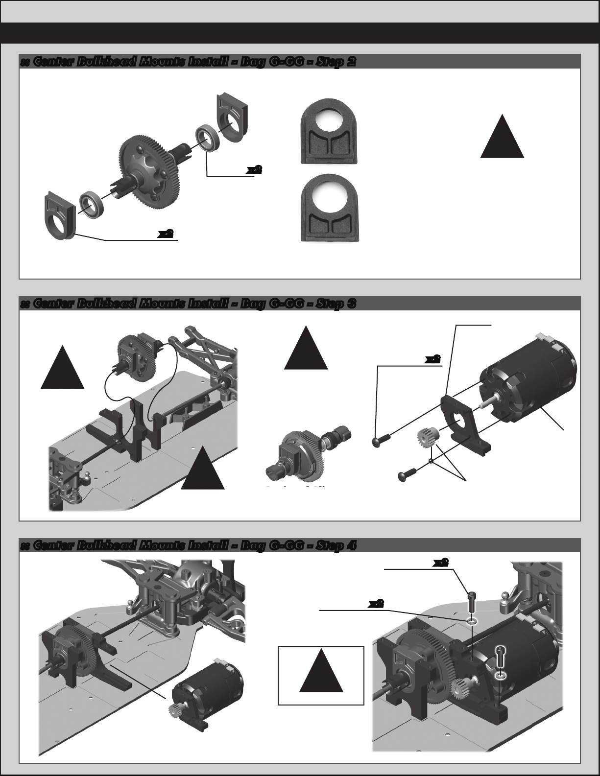
:: Center Bulkhead Mounts Install - Bag G-GG - Step 2
Slipper
(optional)
!
x2
9940
B44.3 center
bearing insert
x2
6903
3/8x5/8
bearing
:: Center Bulkhead Mounts Install - Bag G-GG - Step 3
Gear Diff
assembly
Install
!
!
Note the gear diff
orientation when
installing!
If using the optional slipper,
note the orientation for
installation! (requires
#9947 Center CVA Kit)
NOTE:
Gear Diff
31531
M3x6mm
bhcs
Bearing inserts are included
for both the center gear diff
and the optional slipper.
The gear diff uses the bearing
inserts with the larger hole.
9932
B44.3
motor
x2
mount
Motor not
included!
!
Key CVA bones in
the diff
outdrives!
:: Center Bulkhead Mounts Install - Bag G-GG - Step 4
Optional Slipper
(not included in kit)
9630
Ballstud
washer
!
Set gear mesh!
4-40x3/8
x2
6924
shcs
Pinion and
setscrew not
included!
x2
Page 13

:: Front Top Deck Build - Bag H - Step 1
6937
4-40 blue
aluminum
locknut
x2
9719
Body
mount
9950
B44.3
Top deck,
front
9714
Shock
tower
mount
4334
x2
2-56x5/16
bhcs
13
6936
x2
Washers,
aluminum
#4
6288
4-40x1/4
bhcs
6277
Ballstud, .30
silver, long
x2
:: Front Top Deck Build - Bag H - Step 2
6292
4-40x3/8
fhcs
x5
#1596
thread lock
6917
4-40x3/8
bhcs
6917
4-40x3/8
bhcs
x2
x2
9913
Antenna
mount
:: Rear Top Deck Build - Bag I - Step 1
6292
4-40x3/8
fhcs
#1596
thread lock
9951
B44.3 top
deck, rear
x2
6937
4-40 blue
aluminum
locknut
6936
Washers,
aluminum #4
6277
Ballstud, .30
silver, long
x2
x2
x2
4-40x3/8
9904
Shock tower,
rear
6917
4-40x3/8
bhcs
6924
x2
shcs
x2
9719
Body
mounts
9714
Shock tower
mount
#1596
thread lock
V2 aluminum
shock bushing
7413
4-40x3/4
bhcs
9945
x2
x2
Page 14

14
:: Rear Top Deck Build - Bag I - Step 2
6925
4-40x1/2
shcs
x3
7738
4-40x7/8
shcs
:: Rear Top Deck Build - Bag I - Step 3
6917
4-40x3/8
bhcs
x2
9729
Wing mount
(right, left)
2221
4-40x7/16
bhcs
9913
Center
bulkhead
brace
x2
x4
4449
4-40x3/16
aluminum
locknut
#1596
thread lock
:: Turnbuckles Build - Bag J - Step 1
Front Steering Link
1404
FT titanium
turnbuckles
Front Camber Link
Rear Camber Link
1.77
1406
FT titanium
turnbuckles
2.00
1406
FT titanium
turnbuckles
2.00
7499
Low friction
ball cup
7499
x2
Low friction
ball cup
7499
x2
Low friction
ball cup
x2
Steering
Build x2
60mm
Front Camber
Build x2
64.5mm
Rear Camber
Build x2
67mm
Page 15

:: Front Suspension Build - Bag K - Step 1
15
6272
Foam dust
cover
Right Side
x2
6277
Ballstud, .30
silver, long
4449
4-40x3/16
aluminum
locknut
x2
x2
Left Side
9722
Steering
block
(right, left)
Crush tube
x2
:: Front Suspension Build - Bag K - Step 2
7369
1/16 axle
roll pin
x2
Dust cover
9751
6272
foam
Right Side
x2
x2
3977
3/16x3/8
bearing
x4
4-40x3/16
aluminum
Left Side
4449
locknut
x2
Left Side
Right Side
9750
Axle drive
hex
:: Front Suspension Build - Bag K - Step 3
Left Side
x2
Right Side
Left Side
Ballstud, .30
black, short
3983
x2
Caster block
(right, left)
9720
Right Side
x2
Left Side
Right Side
9647
Steering
block bushing
x4
2221
4-40x7/16
bhcs
x4
Page 16

16
:: Front Suspension Build - Bag K - Step 4
9645
2-56x1/8
bhcs
Build x2 (right and left side)
:: Rear Suspension Build - Bag L-LL - Step 1
9864
FT aluminum
hub ( 0˚)
Left Side
7935
.187x.196
bearing
9716
Hinge pin
set
x2
Molded camber link
tower “A” has
standard holes, and
optional “B” tower
has “in-between” hole
options!
!
Orient the notch
to the left
throughout the
car. It indicates
which end has the
left hand threads!
!
Install x2 (right and left side)
Left Side
3983
Ballstud, .30
black, long
x2
Front
camber
link
Front
steering
link
9872
FT aluminum
hub tower
x2x2
(A)
3977
3/16x3/8
bearing
x2
Crush tube
7933
x2
:: Rear Suspension Build - Bag L-LL - Step 2
7368
3/16
axle shims
x4
A
7369
1/16
roll pins
6272
Dust cover
foam
Build x2 (right and left side)
Build x2 (right and left side)
x2
#1596
thread lock
6932
4-40x5/16
shcs
12mm aluminum
clamping wheel
hex, buggy rear
x4
9890
9660
2-56 x 7/32
shcs
Page 17

:: Rear Suspension Build - Bag L-LL - Step 3
9630
.030 ballstud
washer
31286
Aluminum
ballstud
washer, 1mm
(blue)
!
Orient the notch
to the left
throughout the
car. It indicates
which end has the
left hand threads!
17
Install x2 (right and left side)
Rear
camber
link
9645
2-56x1/8
bhcs
9716
Hinge pin
set
:: Rear Suspension Build - Bag L-LL - Step 4
8830
Anti roll
bar pivots
23mm
9170
4-40x1/2
set screw
8828
Ball cup,
short
x2
Build x2
Install x2 (right and left side)
:: Rear Suspension Build - Bag L-LL - Step 5
4334
2-56x5/16
x2
bhcs
9780
0.47 black
anti-roll bar
89278
Washer,
2.5mm
x2
!
Optional silver
anti-roll bar also
included!
6951
4-40x1/8
setscrew
!
Adjust so that the
anti roll bar is level
and the end link is
90° to the anti roll
bar at ride height.
x2
Make sure endlinks
pivot freely!
Page 18

18
:: Shocks Build - Bag M-MM - Step 1
91308
12mm shock
piston
(1.5 front)
(1.7 rear)
91488
3x21
shock shaft
(front)
91489
3x27.5
shock shaft
(rear)
numbers on the pistons to
make them easily visible!
:: Shocks Build - Bag M-MM - Step 2
91480
12x23mm V2
shock bodies
(front)
91482
12x31mm V2
shock bodies
(rear)
5407
O-ring
91491
Shock
spacer
91491
Shock hat
bushing
x2
x2
6299
1/8 E-clip
!
Racers Tip:
Use a marker over the
91491
12mm shock
cap o-ring
Lightly rub shock oil on the
o-ring before installation!
31327
VCS3 shock
bottom cap
o-ring
#1105
green slime
31327
VCS3 shock
bottom cap
Racers Tip:
Racers Tip:
Coating the o-rings
with green slime
helps seal & reduce
o-ring swell! Green
slime is not
included in kit!
6299
1/8 E-clip
green slime
Front:
1 spacers
Rear:
1 spacers
4187
Nylon spacer,
(.030)
#1105
1777
Shock
eyelet
1777
FT shock
pivot ball
:: Shocks Build - Bag M-MM - Step 3
Step 2-3
Shock oil
#5429
Front Shock: 35 wt
Rear Shock: 35 wt
Shock oil
#5429
91449
12mm
shock cap
x4
Shock Bleeding Steps:
1. Before assembly, get each bleed
screw and thread it 1-2 turns into the
shock cap. This will make installation
easier when you are bleeding your
shocks.
2. Pull shock shaft down.
3. Fill shock body 3/4 full with silicone
shock fluid.
4. Slowly move the shock shaft up and
down to remove air from under the
piston.
5. Wait for bubbles to come to surface.
6. Fill shock body to top with silicone
shock fluid.
7. Place a drop of oil in the cap and on
cap threads.
8. Install cap (without bleed screw) and
tighten completely.
9. Slowly compress shaft all the way to
bleed excess silicone shock fluid out
the hole in the cap (use rag aroundshock to catch excess fluid).
10. Install M2x4mm button head screw
until snug while shaft is fully compressed.
31510
M2x4mm
bhcs
Step 9-10Step 8Step 6-7Step 4-5
x4
Page 19

:: Shocks Build - Bag M-MM - Step 4
19
91304
12mm
threaded
collar
o-ring
91304
12mm
threaded
collar
x4
!
Racers Tip:
Use your finger to rub
shock oil on the o-ring for
smoother adjustment!
12mm front
spring, Red
x4
12mm rear
spring, Green
:: Shocks Build - Bag M-MM - Step 5
6472
Shock
mount nut
91447
Shock
bushing
ball
x2
x2
91332
(3.90lb)
91336
(2.00lb)
Build x2 front and x2 rear shocks
!
Use outside hole
in front arm!
91447
Shock
bushing
ball
x2
Front:
4.5mm
Rear:
1.6mm
91310
12mm shock
spring cup
(5mm offset)
9mm
Offset
5mm
Offset
0mm
Offset
!
Use inside hole
in rear arm!
6925
4-40x1/2
shcs
x2
6472
Shock
mount nut
6925
4-40x1/2
shcs
x2
x2
:: Battery Cradle / Strap Build (Saddle Pack Configuration) - Bag N-NN - Step 1
9905
Battery
cradle
x2
9905
Battery
spacer
x2
9906
Battery
strap
locks
4-40x5/8
set screw
x2
9906
LiPo batteries
not included!
x2
9906
Ball
joint
9906
Battery
straps
x2
x2
6922
4-40x1/2
fhcs
x4
Page 20

20
Servo not
included!
20.5m
:: Battery Cradle / Strap Build (Shorty Pack Configuration) - Bag N-NN - Step 2
9906
Ball
joint
9952
B44.3 shorty
battery
cradle
9952
B44.3 shorty
battery side
rail
9906
Battery
strap
locks
9906
4-40x5/8
set screw
9952
B44.3 shorty
battery strap
6292
fhcs
x2
x2
6922
4-40x1/2
fhcs
4-40x3/8
:: Battery Cradle / Strap Build - Bag N-NN - Step 3
!
Unlocked!
Locked!
LiPo battery
not included!
!
:: Servo Build - Bag O-OO - Step 1
7911
Servo link
20.5m
3981
Ballstud, .20
black, short
6272
Dust cover
foam
89007
Servo horn
ring
Servo screw
not included!
9180
Servo
horn
!
Offset the servo
horn by 5-10 degrees
(approx. one notch)
Servo not
included!
6917
4-40x3/8
bhcs
x2
7336
Servo
spacers
x2
Note the orientation
of #9943 floating
!
servo mount!
7337
washer
9943
B44.3
floating
servo mount
1779
FT Servo
mount
x4
Gold
Page 21

:: Servo Build - Bag O-OO - Step 2
NOTE: You have the
option to use the
non-floating servo
mounting system and use
two #1779 servo mounts
instead. You will need
to purchase a second
#1779 servo mount in
order to do this.
See instructions below!
:: Servo Build - Bag O-OO - Step 3
This is an optional way
to mount your servo by
using two #1779 FT
Servo Mounts.
!
The second #1779
FT Servo Mount is not
included in this kit!
6288
4-40x1/4
bhcs
x3
9944
B44.3 floating
servo brace
1779
x2
FT Servo
mount
6291
4-40x1/4
fhcs
21
x2
4-40x3/8
:: Servo Chart
6917
x2
bhcs
Steering Servo Chart
Associated
Airtronics
Airtronics
Hitec
Hitec
JR
JR
Futaba
Futaba
KO
XP-1015, XP-1313
94102
94257, 94258, 94357,
94358, 94452, 94453, 94755
HS-5625MG, HS-5645MG, HS645MG
HS-965, HS-985MG,
HS-5965, HS-5985MG
Z4750, Z2750
Z250, Z550
S9204, S9250, S9450
S9404
PS-401, PS-2001, PS-2004, PS -2015, PS-2173,
PS-2174, PS-2123, PS-2143, PS -2144
7337
Gold
washer
x4
7336
Servo
spacers
x2
# 9180
servo arm
F
A
A
H
H
J
J
F
F
J
6292
4-40x3/8
fhcs
x2
* Not all servo’s are listed
* Make sure servo linkage clears the servo through full travel in both directions.
Use #7336 servo spacers to adjust the servos position
Page 22

22
ESC / Servo tape
not included!
See ESC
manufacturer’s
instructions for
:: Electronics Install - Saddle Pack Configuration - Step 1
6338
Antenna
tube & cap
6951
4-40x1/8
set screw
Receiver / Servo tape
not included!
ESC / Servo tape
not included!
:: Electronics Install - Shorty Pack Configuration - Step 2
NOTE: There are two
6338
Antenna
tube & cap
6951
4-40x1/8
set screw
ESC / Servo tape
not included!
mounting options for your
electronics in the Shorty
Pack configuration.
!
!
See ESC
manufacturer’s
instructions for
wiring!
See ESC
manufacturer’s
instructions for
wiring!
Receiver / Servo tape
not included!
:: Body, Wheels, Tires Install - Bag P - Step 1
#1597
ca glue
Tires / Inserts
not included!
Carefully apply
tire adhesive to
the tire bead on
both sides.
Do one side at a
time, allow it to
dry before gluing
the other side!
Buggy front
wheel hex,
!
9767
white
x2
Tires / Inserts
not included!
#1597
ca glue
9695
Buggy rear
wheel hex,
white
x2
Page 23

:: Body, Wheels, Tires Install - Bag P - Step 2
6952
8-32
locknut,
steel
23
x2
6953
x2
8-32
LP steel
locknut
:: Body, Wheels, Tires Install - Bag P - Step 3
#0266
Finnisher
X-Flow
body sold
by
JConcepts
1736
FT body
clips, blue
Painting Tips:
Body :
Your B44.3 FT comes with a clear polycarbonate
body. You will need to prep the body before you can
paint it. Wash the inside thoroughly with warm water
and liquid detergent. Dry the body using a clean, soft,
lint-free cloth. Use the supplied window masks to
cover the windows from the INSIDE of the body (RC
cars get painted from the inside).
Using high quality masking tape, apply tape to the
inside of the body to create a design. Spray (either
rattle can or airbrush) the paint to the inside of the
body (prefferably dark colors first, lighter colors last).
NOTE: use ONLY paint that is recommended for use
with (polycarbonate) plastics. If you don’t, you can
destroy the plastic body!!!!).
x2
After painting, cut the body along the trim lines. Make
sure to drill or use a body reamer to make the holes
for the body mounts and antenna!
:: Body, Wheels, Tires Install - Bag P - Step 4
9729
Wing
shims
x2
1736
FT body
clips, blue
High downforce
x2
9772
wing, 6.5”
Page 24

24
:: Tuning Tips
Tips for Beginners:
Before making any changes to the standard setup, make sure you can get around the track without crashing. Changes
to your vehicle will not be beneficial if you can’t stay on the track. Your goal is consistent laps.
Once you can get around the track consistently, start tuning your vehicle. Make only ONE adjustment at a time, testing
it before making another change. If the result of your adjustment is a faster lap, mark the change on the included setup
sheet (make adddtional copies of the sheet before writing on it). If your adjustment results in a slower lap, revert back to
the previous setup and try another change.
When you are satisfied with your vehicle, fill in the setup sheet thoroughly and file it away. Use this as a guide for future
track days or conditions.
Front Camber Link Length & Washers Under Ballstud:
Changing the length of the camber link is considered a bigger step than adjusting the ballstud height. Typically
shortening the camber link (or lowering the ballstud) will give the front end less roll and quicken steering response.
Lengthening the camber link (or raising the ballstud) will give the front more roll and slower steering response. To raise
the ballstud, remove washers from between the ballstud and upper deck.
Front Camber:
A good starting camber setting is –1 degrees. Use the included #1719 camber gage to set your camber.
Positive camber, where the top of the tire is leaning out, is typically not recommended.
Front Toe-In:
Zero degree toe-in (tires pointing straight forward) is the setting that should be used in almost all track conditions.
Occasionally you can increase turn in by adding a little toe-out (front of tires point slightly out). Front toe in is not a typical
tuning adjustment used by The Team.
Front Arm Hole:
The kit silver springs and outside front arm hole will work best in most cases. Moving the shock to the inside hole on the
front arm requires you to add another down travel limiter to the front shocks, so there should be two down travel limiters in each shock. You should also change to a stiffer spring to account for the dif ference in leverage on the shock.
Front Ride Height:
The standard front ride height setting is 21mm. Check the ride height by lifting up the entire car about 8-12 inches
off the bench and drop it. After the suspension “settles” into place, raise or lower the shock collars as necessary until
there is 21 mm gap from the bottom of the chassis to the ground.
Anti-Squat:
Anti-squat denotes the angle of the rear arms relative to the ground. Zero anti-squat means that the rear arms are
flat, parallel with the ground. The kit setting is 2 degrees, and can be reduced to 1 degree by removing the included #4
washer underneath the arm mount. You can add another #4 washer so that there is two washers underneath the arm
mount to get 3 degrees of anti-squat. Adding anti-squat tends to make the car “rotate” more in corners, but doesn’t
handle as well through the bumps. 1 degree will be better in bumpy sections.
Rear Camber Link Length & Washers under Ballstud:
Changing the length of the camber link is considered a bigger step than adjusting the ballstud height on the rear chassis
brace. Typically shortening the camber link (or lowering the ballstud) will give the rear end less roll and the car will tend
to accelerate or “square up” better. Lengthening the camber link (or raising the ballstud) will give the rear more roll and
more cornering grip. To raise the ballstud, remove washers from in-between the ballstud and upper deck. You should
normally use the kit setting and only adjust the ballstud height
Rear Hub Spacing:
You have 3 options for rear hub spacing, FORWARD, MIDDLE, & BACK. The kit setting is FORWARD, which provides
the most rear traction and will be used most often. For improved handling in bumps or rhythm sections, try moving the
hubs to MIDDLE or BACK. This can also make the car handle better in 180 turns.
Anti-Roll Bar:
The #9780 B44 anti-roll bar kit (A.K.A. swaybar) allows you to add roll resistance to the rear end with minimal ef fect on
handling over bumps and jumps. The anit-roll bar is very helpful when trying to tune the suspension. The black bar is the
softest (.047” wire, standard) and the silver (.055” wire) is the hardest. It is popular to run a rear anti-roll bar in 4wd to
help the car square up more out of turns. A front anti-roll bar can also be used, more specifically for higher grip tracks,
where controlling weight transfer is more difficult. A front anti-roll bar helps keep the front flatter on corner entry, and
helps prevent over loading the front outside tire as well as reduce the pitch of the car and maintain consistent grip on all
tires. A rear anti-roll bar will help give the car more steering and square up quicker under acceleration.
Page 25

25
:: Tuning Tips (cont.)
Rear Arm Hole:
The inner hole in the arm tends to work the best over the bumps and jump sections. Changing to the outer hole in the
rear arm will tend to make the rear end feel more “locked in” and less responsive. Making this change to the outer hole
requires you to remove the downtravel limiters from the rear shocks.
Rear Ride Height:
The rear ride height setting you should use most often is 20 mm (the rear arms appear level when looking from the
rear). Check the ride height by lifting up the entire car about 8-12 inches off the bench and drop it. After the suspension
“settles” into place, raise or lower the shock collars as necessary until there is 20 mm gap from the bottom of the
chassis to the ground. Note: Check the ride height gap at the rear end of the carbon fiber chassis, not at the rear
chassis plate which is raised for more ground clearance. The chassis should look level from the side.
Ackerman:
“Ackerman” refers to the relative angle difference between the front wheels as they are turned to steer the car.
More ackerman means that there is a greater difference in angle between the wheels, and the less ackerman you have
the closer the wheels steer parallel to each other. The ackerman on the B44.3 can be adjusted by moving the steering
rack ballstud forwards or back on the steering rack.
The steering ballstud in the back position on the rack (More Ackerman) will make the car more forgiving to drive,
particularly in looser conditions.
The steering ballstud in the forward position on the rack (Less Ackerman) will make the car twitchier around center but
will have more steering mid to corner exit.
Steering Rack:
Front
Back
Battery Placement:
The B44.3 battery cradle allows for quick battery spacing adjustment to fine tune the front to back weight distribution
as needed. A simple rule of thumb to follow is, if your car pushes through the corner, shift the battery back & if it
oversteers in the corner, move the battery forward.
Weight Bias / Motor Orientation:
Running the saddle pack configuration positions the motor forward and overall has a more forward weight bias than the
shorty battery configuration. The weight bias will vary depending on electronics and battery orientation.
Typically a more forward weight bias on higher grip surfaces and more rearward weight bias on lower grip surfaces.
Gear Diff Tuning:
Center:
The center diff has the greatest influence in how the car accelerates and the feel of rear end grip. As the center diff is
tuned with thicker oils it will differentiate less and begin to act more like a slipper or even a spool, and improve straight
line acceleration. When using thinner center diff oils, the car can transfer power from either front or back more
easily. Therefore when accelerating you transfer power to the front due to the weight transfer to the back.
As a result the rear end will usually be more stable and less likely to step out. Typically thicker fluids are used on higher
traction surfaces and thinner on lower bite/ loose surfaces.
Front/ Rear:
When using thicker fluid the car will be less nimble rotating/ steering but it will be a little smoother putting down power
in a straight line. The thinner oil will give the feeling more traction and have more steering but can ‘walk’ and have a little
more instability under hard acceleration due to wheel spin on any corner of the car.
Ball Differential (Option):
Adjust the differential (A.K.A. ‘diff’ for short) as noted in the assembly instructions. Adjusting the rear diff is not meant
to be a tuning option. If you can hear the diff making a “barking” or “chirping” sound on jump landings or under
acceleration, either your diff is set too loose or your slipper clutch is set too tight. The front diff can go out 1/16” turn to
get more steering.
Slipper Clutch (Option):
The assembly instructions give you a base setting for your clutch. To preserve the differentials, always start with the
slipper on the loose side and slowly tighten the adjustment nut until it is set. To adjust the slipper, remove the body and
insert a 2mm (or 5/64”) hex wrench through the center of the top deck (or through the bottom slot in the chassis).
Then, grab both of the rear wheels and rotate forwards to tighten and backwards to loosen. As you spin the wheels,
you’ll feel the motor click every ¼ of a wheel revolution. At the track, tighten or loosen the nut in 2 click increments until
you hear only a faint slipping sound for 1-2 feet on takeoffs.
Page 26

26
:: Notes:
Page 27

27
:: Shocks
1777
FT Blue Aluminum Shock Pivot Ball with Eyelet
4187
.030 Nylon Washer
5407
Red O-Rings
6299
31327
31510
91304
91308
91310
91449
91480
91482
91488
91489
91491
91496
91498
E-Clip
VCS3 Shock Bottom Cap and O-Ring
M2 x 4mm BHCS
12MM Threaded Collar and O-Ring
12MM Shock Pistons, (1.5, 1.6, 1.7)
12MM Shock Spring Cups (+0mm, +5mm, +9mm)
12MM V2 Composite Shock Cap
w/O-ring and bleeder screw
12x23MM V2 Shock Bodies
12x31MM V2 Shock Bodies
3x21MM Shock Shaft
3x27.5MM Shock Shaft
12MM V2 Shock Rebuild Kit
12x23B/21S V2 Shock Kit (B5 Front)
12x31B/27.5S V2 Shock Kit (B5 Rear)
91449
91491
91480
91482
31510
6299
91308
6299
91488
91489
91304
91304
91310
4
12
8
12
2 ea.
6
2
4 ea.
4 ea.
4
2
2
1
1
1
2
2
:: Gear Differentials
3911
6903
6919
9888
9934
9935
9936
9937
9938
9940
9948
9949
31350
31522
91463
Transmission Shim Set
3/8 x 5/8. PTFE Sealed Bearing
4-40 x 5/16 BHCS
0.5mm Gear Diff Shim
B44.3 FT Ring Gear
B44.3 FT F/R Diff Case
B44.3 FT Center Diff Case
B44.3 FT Gerar Diff Outdrives
B44.3 FT 81T Spur, Gear Diff
B44.3 FT Center Bearing Inserts
B44.3 FT F/R Gear Diff, Complete
B44.3 FT Center Gear Diff, Complete
2.5 x 10mm FHCS
2.5 x 10mm BHCS
Gear Diff Rebuild Kit
91463
91463
9937
9888
9888
9934
9937
9888
9888
9935
9937
9888
9888
9937
9937
91463
1
2
6
2
1
1
1
2
1
2ea.
1
1
6
6
1
9940
6903
6919
9938
9936
9936
5407
91491
5407
31327
31327
:: Shock Springs
91325
91326
91327
91328
91329
91330
91331
91332
91333
91334
91335
91336
91337
91338
91339
91340
91341
91342
91343
91344
91345
12MM Front SPRING BRN 2.85
12MM Front SPRING BLK 3.00
12MM Front SPRING GRN 3.15 - Kit
12MM Front SPRING WHT 3.30
12MM Front SPRING GRY 3.45
12MM Front SPRING BLU 3.60
12MM Front SPRING YLW 3.75
12MM Front SPRING RED 3.90
12MM Front SPRING ORN 4.05
12MM Front SPRING PRL 4.20
12MM Rear SPRING BLK 1.90
12MM Rear SPRING GRN 2.00
12MM Rear SPRING WHT 2.10 - Kit
12MM Rear SPRING GRY 2.20
12MM Rear SPRING BLU 2.30
12MM Rear SPRING YLW 2.40
12mm Big Bore Front Soft Spring Kit
12mm Big Bore Front Medium Spring Kit
12mm Big Bore Front Hard Spring Kit
12mm Big Bore Rear Soft Spring Kit
12mm Big Bore Rear Medium Spring Kit
4187
1777
1777
Pr.
Pr.
Pr.
Pr.
Pr.
Pr.
Pr.
Pr.
Pr.
Pr.
Pr.
Pr.
Pr.
Pr.
Pr.
Pr.
9936
31522
6903
9940
31350
3911
3911
3911
6903
9935
3911
3911
3911
6903
:: Shock Oil
5420
5421
5422
5423
5424
5425
5426
5427
5428
5429
5430
5431
5432
5433
5434
1
1
1
1
1
5435
5436
5437
5438
10 Weight Silicone Shock Oil
20 Weight Silicone Shock Oil
30 Weight Silicone Shock Oil
40 Weight Silicone Shock Oil
22.5 Weight Silicone Shock Oil
80 Weight Silicone Shock Oil
27.5 Weight Silicone Shock Oil
15 Weight Silicone Shock Oil
25 Weight Silicone Shock Oil
35 Weight Silicone Shock Oil
45 Weight Silicone Shock Oil
55 Weight Silicone Shock Oil
32.5 Weight Silicone Shock Oil
37.5 Weight Silicone Shock Oil
42.5 Weight Silicone Shock Oil
50 Weight Silicone Shock Oil
60 Weight Silicone Shock Oil
70 Weight Silicone Shock Oil
47.5 Weight Silicone Shock Oil
2oz.
2oz.
2oz.
2oz.
2oz.
2oz.
2oz.
2oz.
2oz.
2oz.
2oz.
2oz.
2oz.
2oz.
2oz.
2oz.
2oz.
2oz.
2oz.
Page 28

28
:: Optional Slipper / Spur Gears / Pinions
1654
7485
7486
7935
9603
9649
9650
9651
9652
9653
9740
9741
9742
9910
9940
9947
91175
91176
91177
91178
91179
FT Axle Pins
FT V2 Slipper Hubs
FT V2 Slipper Spring and Washer
.187 x .50 x .196” Bearing
Slipper Pad
72T 48P Spur Gear
75T 48P Spur Gear
81T 48P Spur Gear (Kit)
78T 48P Spur Gear
84T 48P Spur Gear
B44 Slipper Nut
Slipper Nut O-Ring
B44 Slipper Drive Cups
B44.2 Slipper Shaft
B44.3 FT Center Bearing Inserts
Center CVA Kit (Slipper)
FT VTS Slipper Conversion
VTS Slipper Housing
VTS Slipper Pads
VTS Slipper Plate
FT VTS Slipper Hub, outer
4
2
1
2
2
1
1
1
1
1
1
6
1
1
2ea.
1
1
1
2
1
1
9742
9742
OPTIONAL VTS SLIPPER
9940
7486
9740
9741
91176
1654
9651
7935
9736
91178
91177
91177
:: Pinions
8253
8254
8255
8256
8257
8258
8259
8260
8261
8263
8264
8265
8266
8267
8268
8269
8270
8271
8272
16T 48P Pinion Gear
17T 48P Pinion Gear
18T 48P Pinion Gear
19T 48P Pinion Gear
20T 48P Pinion Gear
21T 48P Pinion Gear
22T 48P Pinion Gear
23T 48P Pinion Gear
24T 48P Pinion Gear
26T 48P Pinion Gear
27T 48P Pinion Gear
28T 48P Pinion Gear
29T 48P Pinion Gear
30T 48P Pinion Gear
31T 48P Pinion Gear
32T 48P Pinion Gear
33T 48P Pinion Gear
34T 48P Pinion Gear
35T 48P Pinion Gear
:: Anti-Roll Bars
6951
8828
8830
9170
9780
4-40 x 1/8” Set Screw
Anti Roll Bar Cups, Set
Anto Roll Bar Pivots (with setscrews), Set
Adjustable Servo Link (contains setscrew)
B44 Anti Roll Bar Kit
7485
9910
1
1
1
1
1
1
1
1
1
1
1
1
1
1
1
1
1
1
1
9910
9603
9910
91179
9940
7935
9742
9742
1654
9742
:: Turnbuckles
6
1
1
1
1
1404
1406
7499
FT Blue Titanium Turnbuckles 1.775” / 45mm
FT Blue Titanium Turnbuckle 2.00 / 51mm”
FT Low Friction Ball Cups
Pr.
Pr.
12
9780 9170-or-
8828
8828
6951
8830
9780
6951
8830
8828
9780 9170-or-
8828
1404
7499
1406
7499 7499
1406
7499 7499
7499
Page 29

:: Front and Rear Gearboxes
3911
3977
4334
6299
6924
7381
7996
9596
9733
9747
9933
9942
9947
89278
Trans. Shim Set
3/16 x 3/8” RS Ball Bearing
2-56 x 5/16” BHCS
1/8” Small E-Clips
4-40 x 3/8” SHCS
CVD Rebuild Kit
CVA Pin Retainer
SC10/T4 CVA Bone
B44 Transmission Case
B44 Front CVA Bone
B44.3 FT Input Pinion Gear
B44.3 FT Input Shaft, Gear Diff
Center CVA Kit (Slipper)
Washer, 2.5mm
:: Steering
1779
3874
3981
6272
6276
6277
6288
6291
6292
6917
7336
7337
7911
9180
9630
9743
9744
9746
9943
9944
89007
FT Servo Mount, blue
Block Carrier Bushings
Ballstud .20” Black, short
Foam Ballend Dust Covers
Ballstud .20” Silver, short
Ballstud .30” Silver, short
4-40 x 1/4” BHCS
4-40 x 1/4” FHCS
4-40 x 3/8” FHCS
4-40 x 3/8” BHCS
Steering Servo Mount Kit
.250 x .125 x .015” Washer
Steering Servo Link
Servo Horns, Molded
Ballstud Washer
B44 Steering Set
B44 Steering Hardware
B44 Steering Bearing Set
FT Floating Servo Mount
FT Floating Servo Brace
Steering Servo Ring, blue
0
4
6
28
6
6
6
6
6
6
1
4
1
1
10
1
1
1
1
1
1
1
2
8
12
6
1
2
2
1
2
1
2
1
20
9743
6917
9630
6277
6272
3874
6917
9743
9630
6277
6924
4334
89278
9743
9746
9744
9743
9744
6272
6292
6924
89278
9733
9744
6292
9746
9744
9744
9744
9743
6924
4334
6272
6276
9743
9746
6924
6924
9733
7337
6917
6924
6299
7336
3911
6291
3911
9933
6288
9943
6917
3977
6288
7337
7381
9942
7996
6288
9944
7336
9747 - Front
9596 - Rear
1779
7381
7911
3981
9180
29
7911
7911
6272
89007
:: Front and Rear Shock Towers
1736
4449
6472
6917
7413
7738
7874
9719
9729
9772
9903
9904
9945
91447
FT Body Clips, Short, blue
4-40 x 3/16” Alum. Locknut
4-40/5-40 Plastic Nut
4-40 x 3/8” BHCS
4-40 x 3/4” BHCS
4-40 x 7/8” SHCS
4-40 x 7/16” SHCS
B44 Body Mounts
B44 Wing Mounts
High Downforce Wing 6.5”
B44.2 Front Shock Tower
B44.2 Rear Shock Tower
V2 Aluminum Shock Bushing
Shock Bushing Ball
6
5
4
6
6
6
8
1
1
1
1
1
4
4
7413
6917
6917
6917
9945
6917
7874
9903
91447
6472
6917
9719
6472
91447
7413
9945
9945
6472
6917
1736
7413
9904
9945
6472
7413
4449
91447
9729
9729
1736
9772
9729
9729
7738
Page 30

30
:: Front and Rear Top Plates
1736
4334
4449
6277
6288
6292
6338
6917
6925
6936
6951
9714
9719
9913
9950
9951
FT Body Clips, Short, blue
2-56 x 5/16” BHCS
4-40 x 3/16” Alum. Locknut
Ballstud .30” Silver, short
4-40 x 1/4” BHCS
4-40 x 3/8” FHCS
Antenna Tube 12”, black
4-40 x 3/8” BHCS
4-40 x 1/2” SHCS
Washers, Alum. #4
4-40 X 1/8” Set Screw
B44 Shock Tower Mounts
B44 Body Mounts
Antenna Mount
B44.3 FT Front Top Deck
B44.3 FT Rear Top Deck
10
6
8
5
6
6
6
1
6
6
6
1
1
1
1
1
9714
4449
6925
6925
6925
4449
6951
6338
6338
4334
9913
4334
4449
6936
6277
6917
6292
6917
9714
9719
6292
6292
6288
1736
6936
6277
4449
6292
6292
6292
9950
6292
9951
6277
6936
6936
6277
:: Center Bulkhead and Motor Mount
2221
6292
6924
9630
9913
9931
9932
31531
4-40 x 7/16” BHCS
4-40 x 3/8” FHCS
4-40 x 3/8” SHCS
Ballstud Washer
B44.2 Center Bulkhead Brace
B44.3 FT Center Bulkhead
B44.3 Motor Mount
M3 x 6mm BHCS
6
6
6
10
1
1
1
6
6924
9630
6924
9932
9630
9932
2221
6292
2221
2221
2221
9913
31531
9931
6292
6292
6292
Page 31

:: Front Suspension
2221
3977
3983
4449
6272
6277
6925
6953
7369
7381
7996
9645
9647
9715
9716
9720
9722
9747
9748
9749
9750
9751
4-40 x 7/16” BHCS
3/16 x 3/8” RS Ball Bearing
Ballstud .30” Black, short
4-40 x 3/16” Alum. Locknut
Foam Ballend Dust Covers
Ballstud .30” Silver, short
4-40 X 1/2” SHCS
8-32 LP Steel Locknut
1/16” Universal Roll Pins
CVD Rebuild Kit
PosiLock QC Pin Retainer
2-56 x 1/8” BHCS
B44 Steering Block Bushing
B44 Front Arms
B44 Hinge Pin Set
B44 Caster Block
B44 Steering Block
B44 Front CVA BoneB44
Front CVA Axle
FT Front CVA Kit
B44 Axle Drive Hex
B44 Front Crush Tube
28
Pr.
Pr.
Pr.
31
6
2
6
5
6
6
6
4
1
2
6
4
1
2
2
1
2
2
9747
7381
9716
6925
7381
9748
7996
7369
6272
9715
3983
9720 9722
9647
4449
2221
2221
9751
6277
4449
3977
9750
6272
6953
:: Rear Suspension
3977
3983
6272
6925
6932
6952
7368
7369
7381
7933
7935
7996
9630
9645
9660
9716
9754
9755
9756
9764
9864
9872
9890
31286
3/16 x 3/8” RS Ball Bearing
Ballstud .30” Black, short
Foam Ballend Dust Covers
4-40 X 1/2” SHCS
4-40 x 5/16” SHCS
8-32 Locking Nut, Steel
3/16” Axle Shims
1/16” Universal Roll Pins
CVD Rebuild Kit
Crush Tube GT2
.187 x .50 x .196” Bearing
PosiLock QS Pin Retainer
Ballstud Washer
2-56 x 1/8” BHCS
2-56 x 7/32” SHCS
B44 Hinge Pin Set
B44 Rear CVA Bone
CVA Axle, rear
FT Rear CVA Kit
B44 Rear Arm
B44 FT Aluminum Hub, 0˚
B44 FT Aluminum Hub Tower Set
12mm Aluminum Clamping Wheel
Hex, Buggy Rear
Alum. Ballstud Washer (1mm, 2mm)
2
6
28
6
6
6
14
4
1
2
2
2
10
6
6
1
2
1
1
Pr.
Pr.
1
2
4 ea.
9754
7381
9645
9716
7381
9755
9716
7369
7996
9764
7368
6272
3983
6932
3977
9864
9872
9630
7933
7935
31286
7368
9890
9645
6925
6952
9716
9660
Page 32

32
6
6
:: Chassis and Battery Mounts
4449
6292
6915
6917
6922
6936
7673
9645
9713
9717
9718
9726
9765
9905
9906
9946
9952
4-40 x 3/16” Alum. Locknut
4-40 x 3/8” FHCS
4-40 x 5/8” FHCS
4-40 x 3/8” BHCS
4-40 X 1/2” FHCS
Washers, Alum. #4
4-40 x 5/16” FHCS
2-56 x 1/8” BHCS
B44 Front Bulkhead
Front Hinge Pin Brace
B44 Front & Rear Bumper
B44 Rear Chassis Plate, 3˚ arm mount
4-40 x 7/16” FHCS
B44.2 Battery Cradle
B44.2 Battery Straps
B44.3 FT Aluminum Chassis
B44.3 FT Shorty Battery Cradle
5
6
6
6
6
10
6
4
1
1
1 ea.
1
6
1
1
1
1
9905
9906
9906
9906
9905
9906
9906
9906
9906
9906
9905
9645
9717
9718
9645
6917
9713
6292
6292
6917
4449
6292
9765
6292
9946
9726
6936
9726
6915
4449
4449
6292
9765
4449
6292
7673
6292
6915
4449
9645
6936
7673
6292
9718
9645
7673
9952
6922
9906
9906
6922
6922
6922
6292
9906
6922
9905
9905
6922
9952
9952
6292
Page 33

33
:: Factory Team and Option Parts
1404
1406
1411
1654
1734
1735
1736
1777
1779
1780
1787
3911
6584
6860
6906
6937
6943
9721
9733
9734
9735
9742
9776
9779
9783
9784
9787
9795
9796
9797
9798
9799
9864
9865
9866
9867
9872
9873
9890
9915
9916
9917
9918
9919
9925
9941
9947
9953
31286
91170
Ti Turnbuckle 1.775” Blue
Ti Turnbuckle 2.00” Blue
Ti Turnbuckle 0.75” Blue
FT Solid Axle Pins
FT Blue Body Clips, 4 Long, 6 Short
FT Blue Body Clips, Long
FT Blue Body Clips, Short
FT Blue Aluminum Ball/Eyelet Set
FT Servo Mount Blue Aluminum
FT Aluminum Shock Bushing
Battery Strap Thumbscrew
Transmission Shim Set
3/32” Ceramic Diff Balls
4-40 x 3/8” SH Screw, Blue Alum.
3/16 x 3/8” PTFE Bearings
FT Blue 4-40 Locknuts
FT Blue 8-32 Locknuts
B44 Aluminum Caster Blocks
Transmission Case, top and bottom
FT Outdrive (for use with optional ball diff)
FT Complete Diff Kit
Slipper Drive Cup
FT B44.1 Ballast Weight
FT B44 Complete Bearing Set
B44 Aluminum Front Tower Mount
B44 Aluminum Rear Tower Mount
Chassis Protective Sheet
Ti Nitride Ballstuds 4-40 x 0.20” Long
Ti Nitride Ballstuds 4-40 x 0.30” Long
Ti Nitride Ballstuds 4-40 x 0.40” Long
Ti Nitride Ballstuds 4-40 x 0.20” Short
Ti Nitride Ballstuds 4-40 x 0.30” Short
B44 FT Aluminum Hub, 0˚ - Kit
B44 FT Aluminum Hub, 0.5˚
B44 FT Aluminum Hub, 1˚
B44 FT Aluminum Hub, 1.5˚
B44 FT Aluminum Hub Tower Set
FT Aluminum Hub Tower C, graphite
12mm Alum. Clamping Wheel Hex, Buggy Rear
Graphite Battery Strap
Graphite Center Brace
Aluminum Hub Tower A, Graphite
Aluminum Hub Tower B, Graphite
B44.2 Aluminum Screw Set
FT 12mm Clamping Wheel Hex, Rear (narrow)
Center CVA Kit (for Gear Differential)
Center CVA Kit (for Slipper)
B44.3 FT Shorty Graphite Battery Strap
FT Ballstud Washer, Aluminum 1mm, 2mm each
FT High Torque Slipper Pad
:: XP Electronics
29166
29167
29209
29210
29211
29212
XP DS1313 Digital Servo
XP DS1015 Digital Servo
Gear Set, DS1313
Gear Set, DS1015
Servo Case , DS1313/DS1015
Accessory Pack, DS1313/DS1015
:: Reedy Accessories
2
2
2
4
1
4
6
1
2
4
2
1
12
6
Pr.
6
4
Pr.
1
1
1
1
1
1
1
1
1
2
2
2
2
2
Pr.
Pr.
Pr.
Pr.
1
2
2
1
1
Pr.
Pr.
1
2
1
1
1
1
2
1
1
1
1
1
1
247
248
249
250
606
607
611
643
644
645
646
647
648
649
650
654
655
656
657
658
659
668
669
962
978
979
980
981
982
994
995
996
997
998
999
:: Reedy Motors and ESC’s
228
231
232
233
233S
234
235
236
237
238
239
240
241
242
243
244
245
246
941S
954
955
956
957
958
987
Sonic 540 Mach 2 Sensor w/bearing
Sonic 540 Mach 2 Steel Bearing Set
Sonic 540 Mach 2 Ceramic Bearing Set
Sonic 540 Mach 2 Insulator Set
Charge Harness 2S Saddle Pack 4mm
Charge Harness 2S Standard Pack 4mm
Charge Harness 2S Standard Pack 5mm
Low Profile Bullet Plug 4mm x 14mm (2)
Low Profile Bullet Plug 4mm x 14mm (10)
Low Profile Bullet Plug 5mm x 14mm (2)
Low Profile Bullet Plug 5mm x 14mm (10)
Silicone Wire 12AWG-Black (1m)
Silicone Wire 14AWG-Black (1m)
Silicone Wire 16AWG-Black (1m)
Shrink Tubing - 15pcs 4.5mm x 20mm
4.0mm Bullet Plugs (2M, 2F)
4.0mm Bullet Plugs (2M, 10F)
4.0mm Bullet Plugs (10F)
4.0mm Bullet Plugs (100F)
4.0mm Bullet Plugs (10M)
4.0mm Bullet Plugs (30M)
Charge Harness 4S 5mm (for Reedy #311)
5.0mm Bullet Plugs (2M)
Sonic 540/540 Mach 2 Case Screws (3 pcs.)
Flat Sensor Wire 70mm
Flat Sensor Wire 110mm
Flat Sensor Wire 150mm
Flat Sensor Wire 200mm
Flat Sensor Wire 270mm
Flat Sensor Wire 125mm
Flat Sensor Wire 175mm
5.0mm 1S-2S Balance Charge lead w/SP Clip
4.0mm 1S-2S Balance Charge lead w/SP Clip
5.0mm 4S Balance Charge Lead
Saddle Pack Balance Charge Clip
Sonic 540 Mach 2 25.5 Competition Brushless Motor
Sonic 540 Mach 2 21.5 Competition Brushless Motor
Sonic 540 Mach 2 17.5 Competition Brushless Motor
Sonic 540 Mach 2 13.5 Competition Brushless Motor
Sonic 540/540 Mach 2 Stator 13.5
Sonic 540 Mach 2 10.5 Competition Brushless Motor
Sonic 540 Mach 2 9.5 Competition Brushless Motor
Sonic 540 Mach 2 8.5 Competition Brushless Motor
Sonic 540 Mach 2 8.0 Competition Brushless Motor
Sonic 540 Mach 2 7.5 Competition Brushless Motor
Sonic 540 Mach 2 7.0 Competition Brushless Motor
Sonic 540 Mach 2 6.5 Competition Brushless Motor
Sonic 540 Mach 2 6.0 Competition Brushless Motor
Sonic 540 Mach 2 5.5 Competition Brushless Motor
Sonic 540 Mach 2 5.0 Competition Brushless Motor
Sonic 540 Mach 2 4.5 Competition Brushless Motor
Sonic 540 Mach 2 4.0 Competition Brushless Motor
Sonic 540 Mach 2 3.5 Competition Brushless Motor
Sonic 540/540 Mach 2 Stator 17.5
Sonic 540 Stock Rotor 12.3 x 24.2 (7.25)
Sonic 540 Stock Rotor 12.3 x 25.0 (7.25)
Sonic 540 Stock Rotor 12.5 x 25.0 (7.25)
Sonic 540 Modified Rotor 12.2 x 25.0 (5.0)
Sonic 540 Modified Rotor 12.5 x 25.0 (5.0)
Sonic 540 Modified Rotor 13.0 x 25.0 (5.0)
1
1
1
1
1
1
1
1
1
1
1
1
1
1
1
1
1
1
1
1
1
1
1
1
1
1
1
1
1
1
1
1
1
1
1
1
1
1
1
1
1
1
1
1
1
1
1
1
1
1
1
1
1
1
1
1
1
1
1
1
Page 34

34
:: Reedy Electronics
27000
27001
27020
27021
27022
27023
27024
27025
604
Blackbox 410R 1S-2S Competition ESC
Blackbox 410R 1S-2S Competition ESC
w/PROgrammer
Blackbox ESC PROgrammer
Blackbox 410R Fan w/Screws
Blackbox 410R Heavy-Duty Capacitor Unit
Blackbox 410R XL Capacitor Unit
Blackbox 410R Pro Capacitor Unit
Blackbox ESC PROgrammer Wire Extension
526-S AC/DC 2S-6S LiPo/LiFe Charger
:: Reedy Batteries
302
304
305
309
310
311
312
313
314
315
316
317
602
626
637
737
738
739
AA Alkaline 1.5V (4)
LiPo Pro TX/RX Battery 1600mAh 7.4V Flat
LiFe Pro TX/RX Battery 1300mAh 6.6V Flat
LiPo 65C 7000mAh 7.4V
LiPo 65C 5700mAh 7.4V SP
LiPo 65C 4600mAh 14.8V
LiPo 65C 7000mAh 3.7V
LiPo 65C 7000mAh 7.4V 5mm
LiPo 65C 5800mAh 7.4V SQ
LiPo Pro TX/RX Battery 2100mAh 7.4V Flat
LiPo 65C 5000mAh 7.4V
LiPo 50C 5200mAh 7.4V SQ
LiPo 65C 4100mAh 7.4V Shorty
LiPo 60C 5500mAh 14.8V
LiPo TX Battery - M11X 2500mAh 7.4V
Wolfpack LiPo 4800mAh 7.4V 25C S.P.
Wolfpack LiPo 3800mAh 7.4V 25C Shorty
Wolfpack LiPo 5500mAh 7.4V 60C
:: 1/18 Kits and RTR’s
1
20103
1
20121
1
1
1
1
1
1
:: Qualifier Series Vehicles
1
7052
1
7070
20111
20119
20510
30112
1
1
1
1
1
1
1
1
1
1
:: 1/12, 1/10 Kits and RTR’s
1
4020
1
7025
1
7030
1
7038
1
7039
1
7046
1
7049
1
7050
7093
9042
9050
9063
30101
30109
90001
90003
RC18B2 - RC18T2 Team Kit
SC18 RTR Brushless (ready-to-run)
Pro Lite 4x4 RTR, 1/10 Scale (ready-to-run)
Pro Rally 4wd RTR, 1/10 Scale (ready-to-run)
Rival Mini Monster Truck 1/18 Scale (ready-to-run)
APEX Mini Touring RTR
RIVAL Electric Monster Truck RTR, 1/8 Scale
(ready-to-run)
APEX Touring V-Type, 1/10 Scale (ready-to-run)
FT 12R5.2 Kit
FT RC10T4.2 Kit
SC10 KMC Wheels Race Truck RTR (ready-to-run)
FT SC10.2 Kit
RC10T4.2 RS RTR 2.4GHz Brushless (ready-to-run)
SC10 RS RTR, Lucas Oil (ready-to-run)
SC10 RS RTR, Rockstar/Makita (ready-to-run)
SC10 RS RTR, Hart and Huntington (ready-to-run)
SC10GT RTR (ready-to-run)
RC10B4.2 RS RTR 2.4GHz Brushless (ready-to-run)
SC10B RS RTR (ready-to-run)
FT B44.3 4WD Buggy Kit
TC4 Club Racer 4WD Touring Car Race Roller
FT TC6.2 Kit
RC10B5 Team Kit
RC10B5M Team Kit
1
1
1
1
1
1
1
1
1
1
1
1
1
1
1
1
1
1
1
1
1
1
1
1
:: Lubes & Adhesives / Decals / Misc.
1105
1596
1597
5450
5451
5452
5453
5454
5455
5456
5457
5458
5459
6588
6591
6636
6727
716
717
3816
3820
3834
9787
FT Green Slime Shock Lube
FT Locking Adhesive
FT Tire Adhesive, Medium
Silicone Diff Fluid 1000cst
Silicone Diff Fluid 2000cst
Silicone Diff Fluid 3000cst
Silicone Diff Fluid 5000cst
Silicone Diff Fluid 7000cst
Silicone Diff Fluid 10000cst
Silicone Diff Fluid 20000cst
Silicone Diff Fluid 30000cst
Silicone Diff Fluid 60000cst
Silicone Diff Fluid 100000cst
Black Grease - 4cc
S.Diff Lube - 4cc
Silicone Grease - 4cc
Servo Tape
Reedy 2009 Sticker Set
Reedy Powered Logo Decal
American Bumper Sticker
AE Logo Decal Sheet
AE Blue Embossed Logo Sticker
FT Chassis Protective Sheet
1
1
1
1
1
1
1
1
1
1
1
1
1
1
1
1
2
1
1
1
1
2
1
1596
:: 1/8 Kits and RTR’s
20501
20502
20503
20504
80907
80908
80909
80912
MGT 4.60 SE RTR (ready-to-run)
MGT 8.0 Nitro RTR (ready-to-run)
Limited Edition MGT 4.60 Nitro RTR, w/flag body
(ready-to-run)
Limited Edition MGT 8.0 Nitro RTR, w/flag body
(ready-to-run)
RC8.2e Electric Buggy FT Kit
RC8.2e Electric Buggy RTR (ready-to-run)
RC8.2RS Nitro Buggy RTR (ready-to-run)
RC8T Championship Edition
1
1
1
1
1
1
1
1
Page 35

35
:: Apparel
SP20
SP21
SP23**
SP24**
SP31**
SP32**
SP37**
SP38
SP39
SP77**
SP78**
SP79**
SP84**
SP85**
SP86**
SP87**
SP90**
SP91**
SP92**
SP93**
SP94**
SP95**
:: Notes
SP96**
SP98**
SP420**
SP421S
SP421L
SP422S
SP422L
SP423S
SP423L
SP424S
SP424L
715
110684
AE Patch Trucker Hat
AE Patch
AE Splash T-shirt - Black (S, M, L, XL, 2-5XL)
AE Splash T-shirt - Blue (S, M, L, XL, 2-5XL)
27 Time WC T-shirt - Black (S, M, L, XL, 2XL, 3XL)
AE Kids T-shirt - Blue (S, M, L)
Reedy 2012 T-shirt - Black (S, M, L, XL, 2XL, 3XL)
Reedy Trucker Hat
Reedy Patch
AE 2012 T-Shirt, Blue (S, M, L, XL, 2XL, 3XL)
AE 2012 T-Shirt, White (S, L, XL, 3XL)
AE 2012 T-Shirt, Black (S, M, L, XL, 2XL, 3XL)
Reedy 3D T-Shirt, Black (S, M, L, XL, 2XL, 3XL)
Reedy Zip Hoodie, Black (S, M, L, XL, 2XL, 3XL)
Reedy Girl’s 3D T-Shirt, Black (S, M, L, XL)
AE 2013 Zip Hoodie (S, M, L, XL, 2XL, 3XL)
AE Retro T-shirt, Blue (S, M, L, XL, 2-5XL)
AE Retro T-shirt, Black (S, M, L, XL, 2-5XL)
AE Retro T-shirt, White (S, M, L, XL, 2-5XL)
AE 2013 Worlds T-shirt - Blue (S, M, L, XL-5XL)
AE 2013 Worlds T-shirt - Black (S, M, L, XL-5XL)
AE 2013 Worlds Hoodie - Black (S, M, L, XL-3XL)
AE Womens Retro - Pink (S, M, L, XL)
AE Womens Retro - Black (S, M)
AE Pit Gloves (L, XL)
AE 2012 Hat, Black, Flat Bill, S/M
AE 2012 Hat, Black, Flat Bill, L/XL
AE 2012 Hat, Black, Curved Bill, S/M
AE 2012 Hat, Black, Curved Bill, L/XL
AE 2012 Hat, White, Flat Bill, S/M
AE 2012 Hat, White, Flat Bill, L/XL
AE 2012 Hat, White, Curved Bill, S/M
AE 2012 Hat, White, Curved Bill, L/XL
Reedy 2009 Track Banner
Team Associated Track Banner
:: RePlay Cameras
RP002
RP004
RP021
RP022
RP023
RP029
RP030
RP032
RP033
RP034
RP036
RP038
RP041
RP042
RP043
RP044
RP045
RP046
RP047
RP048
RP049
RP050
RP054
Replay XD720 Complete Camera System
Replay XD1080 Mini Complete Camera System
Replay XD1080 Lens Bezel Kit
Replay XD1080 Clear Lens Cover
Replay XD1080 Lens Bezel & Rear Cap O-Ring
Replay XD1080 HDMI to Mini-HDMI
Replay XD1080 Mini 8-pin USB Charge Data Cable
USB DC Car Charger 1A Stubby
USB DC Car Charger 500mAh
Micro SDHC USB Reader
3M VHB 4991 Mount Adhesive for SnapTray
3M VHB 5962 Mount Adhesive for SnapTray
Replay XD Suction Cup Arm Mini Clamp
Replay XD Suction Cup Short Arm Base
Replay XD Skateboard Mount
Replay XD VHB SnapTray, Convex
Replay XD VHB SnapTray, Flat
Au Plug for Universal DC Wall Charger
Eu Plug for Universal DC Wall Charger
Uk Plug for Universal DC Wall Charger
Universal USB DC Wall Charger 1A
Au Plug for Uni DC Wall Charger
Replay ReView Field Monitor
1
1
1
1
1
1
1
1
1
1
1
1
1
1
1
1
1
1
1
1
1
1
1
1
Pr.
1
1
1
1
1
1
1
1
1
1
1
1
1
1
1
1
1
1
1
1
1
1
1
1
1
1
1
1
1
1
1
1
1
:: Tools
1111
1112
1449
1541
1542
1543
1544
1545
1546
1547
1548
1551
1553
1554
1561
1562
1563
1564
1565
1567
1568
1569
1570
1589
1590
1592
1655
1656
1657
1658
1659
1660
1661
1662
1663
1664
1665
1666
1667
1668
1669
1670
1671
1672
1673
1674
1719
1737
3718
3719
3720
3987
6429
6956
7494
7709
SP29
SP30
FT Turnbuckle Wrench
FT 4mm Turnbuckle Wrench
FT Off Road Ride Height Gauge
FT Hex Driver Set, (7 pcs)
FT .050” Silver Hex Driver
FT 1/16” Black Hex Driver
FT 1.5mm Purple Hex Driver
FT 5/64” Blue Hex Driver
FT 3/32” Gold Hex Driver
FT 2.5mm Green Hex Driver
FT 3mm Red Hex Driver
FT Screwdriver Set
FT Phillips Silver Screwdriver
FT Silver Spring Hook Tool
FT Nut Driver Set, (6 pcs)
FT 3/16” Black Nut Driver
FT 1/4” Red Nut Driver
FT 5.5mm Red Nut Driver
FT 11/32” Green Nut Driver
FT 8mm Gold Nut Driver
FT 5.5mm Short Nut Driver
FT 7mm Nut Driver, T-Handle
FT 7.0mm Short Nut Driver
FT 5/64” Blue Ball Hex Driver
FT 3/32” Gold Ball Hex Driver
FT Ball Hex Driver Set, (3 pcs)
FT 8-Piece 1/4” Hex Drive Set
FT 1/4” Hex Drive Handle, without tips
FT 1/4” Hex Drive .050” Tip
FT 1/4” Hex Drive 1/16” Tip
FT 1/4” Hex Drive 5/64” - 2.0mm Tip
FT 1/4” Hex Drive 3/32” Tip
FT 1/4” Hex Drive 1.5mm Tip
FT 1/4” Hex Drive 2.5mm Tip
FT 1/4” Hex Drive 3/16” Nut Driver Tip
FT 1/4” Hex Drive 1/4” Nut Driver Tip
FT 1/4” Hex Drive 11/32” Nut Driver Tip
FT 1/4” Hex Drive 5.5mm Nut Driver Tip
FT 1/4” Hex Drive 7.0mm Nut Driver Tip
FT 1/4” Hex Drive 8.0mm Nut Driver Tip
FT 1/4” Hex Drive 5/64” - 2.0mm Ball End Tip
FT 1/4” Hex Drive 3/32” Ball End Tip
FT 1/4” Hex Drive Standard Screwdriver Tip
FT 1/4” Hex Drive Phillips Screwdriver Tip
FT 1/4” Hex Drive 2.5mm Ball End Tip
FT 1/4” 5 Piece Power Tool Tips Set (5/64-2.0mm,
1.5mm, 2.5mm, 5/64”- 2.0mm ball, 2.5mm ball)
FT Camber + Track Width Tool
FT Body Scissors
12 Inch Nylon Wire Ties
6 Inch Nylon Wire Ties
8 Inch Nylon Wire Ties
FT Droop Gauge
Shock Building Tool
Molded Tools, Set
V2 Stamped Multi-Tool
4 Inch Nylon Wire Ties
Team Associated Countertop/Setup Mat
Team Associated Pit Mat
Associated Electrics, Inc.
26021 Commercentre Drive
Lake Forest, CA 92630-8853 USA
http://www.TeamAssociated.com
http://www.RC10.com
http://twitter/Team Associated
http://bit.ly/AEonFacebook
call: (949) 544-7500
fax: (949) 544-7501
Check out the following web sites for all of
our electric kits, current products, new
releases, setup help, tips, and racing info!
www.TeamAssociated.com. - www.RC10.com
1
1
1
1
1
1
1
1
1
1
1
1
1
1
1
1
1
1
1
1
1
1
1
1
1
1
1
1
1
1
1
1
1
1
1
1
1
1
1
1
1
1
1
1
1
1
1
1
12
12
12
1
1
1
1
12
1
1
Page 36

Setup Sheet
Front Suspension
Anti Roll Bar:
0.047” Black
0.055” Silver
None
A B
Driver: Date:
Kit Setup
Track: Event:
Conditions: Rev.1
Rear Suspension
3
2
1
Anti Roll Bar:
0.047” Black
0.055” Silver
None
3
2
1
Bumpsteer
Washer:
Camber:
Toe:
Ride Height:
Steering Rack:
Steering Rack
Washers:
0°
I O
Notes:
0
1°
21mm
Back
Front
1
Washers:
2
Camber:
Toe:
Ride Height:
Anti-Squat:
Aluminum
Hub Tower:
1
1
A
B
C
Wheelbase:
Long
Medium
Short
-1°
3°
20mm
0.030”
Washers:
A CB D
1
1
2
I O
Notes:
Front Shocks
Spring: Piston:
Shock Oil: Limiter: Stroke:
Drivetrain Electronics
Slipper: Yes No
Type:
Pads:
Notes:
Tires
Tire (F/R): /
Compound (F/R): /
Insert (F/R): /
Wheel (F/R): /
Notes:
Other Weight
Body Type:
Wing Type: Wing Angle:
Race and Vehicle Comments
Qualify: Main: Finish: TQ:
Comments:
Red 3.90lb Green 2.00lb
35wt 35wt
JConcepts Finnisher X-Flow #0266
6.5” High Downforce
1 121mm 26.5mm
Differentials
Front:
Center:
Rear:
Notes:
1.5 1.7
5k
60k
5k
Rear Shocks
Spring: Piston:
Shock Oil: Limiter: Stroke:
Radio:
Throttle / Brake E.P.A.:
Throttle / Brake Expo:
Servo: Steering Expo:
ESC:
ESC Settings:
Motor & Wind:
Pinion: Spur Gear:
Batteries:
Motor Placement: Front Back
Battery Placement: Front Back Shorty
Ballast Weight:
Chassis Weight: Total:
Track Info
Smooth: Bumpy: Blue Groove:
Traction: High: Medium: Low:
Soft Dirt: Grass: Clay: Wet:
Dusty: Other:
:: For more setups, visit RC10.com and click on “Setup Sheets”
Page 37

Setup Sheet
Front Suspension
Anti Roll Bar:
0.047” Black
0.055” Silver
None
A B
Driver: Date:
Track: Event:
Conditions: Rev.1
Rear Suspension
3
2
1
Anti Roll Bar:
0.047” Black
0.055” Silver
None
3
2
1
Bumpsteer
Washer:
Camber:
Toe:
Ride Height:
Steering Rack:
Steering Rack
Washers:
I O
Notes:
Back
Front
Washers:
2
Camber:
A CB D
Toe:
Ride Height:
Anti-Squat:
Aluminum
Hub Tower:
A
B
C
1
Wheelbase:
Long
Medium
Short
Washers:
1
2
I O
Notes:
Front Shocks
Spring: Piston:
Shock Oil: Limiter: Stroke:
Drivetrain Electronics
Slipper: Yes No
Type:
Pads:
Notes:
Tires
Tire (F/R): /
Compound (F/R): /
Insert (F/R): /
Wheel (F/R): /
Notes:
Other Weight
Body Type:
Wing Type: Wing Angle:
Race and Vehicle Comments
Qualify: Main: Finish: TQ:
Comments:
Differentials
Front:
Center:
Rear:
Notes:
Rear Shocks
Spring: Piston:
Shock Oil: Limiter: Stroke:
Radio:
Throttle / Brake E.P.A.:
Throttle / Brake Expo:
Servo: Steering Expo:
ESC:
ESC Settings:
Motor & Wind:
Pinion: Spur Gear:
Batteries:
Motor Placement: Front Back
Battery Placement: Front Back Shorty
Ballast Weight:
Chassis Weight: Total:
Track Info
Smooth: Bumpy: Blue Groove:
Traction: High: Medium: Low:
Soft Dirt: Grass: Clay: Wet:
Dusty: Other:
:: For more setups, visit RC10.com and click on “Setup Sheets”
Page 38

current products, new releases, setup help, tips, and racing info!
Check out the following web sites for all of our kits,
www.TeamAssociated.com. - www.RC10.com
call: (949) 544-7500 - fax: (949) 544-7501
http://twitter/Team_Associated
http://bit.ly/AEonFacebook
http://www.TeamAssociated.com
Lake Forest, CA 92630 USA
26021 Commercentre Dr.
http://www.RC10.com
Associated Electrics, Inc.
 Loading...