

Page 1

Page 2

WARRANTY REGISTRATION
Keep your purchase receipt to enable you to proceed quickly in the event of a Warranty Service.
Please read this warranty card.
Warranty Terms & Conditions
1. TEAC warrants to the original retail purchaser only, that this product is free from defects in material and
workmanship under normal domestic use and authorises free service during the warranty period at any TEAC
Authorised Centre only. TEAC warranty only applies to products purchased, used and serviced in Australia.
2. Subject to the terms herein, this warranty effectively covers the equipment as specified in the Warranty Periods
Table from the date of purchase.
3. All parts, except the external cabinet, are warranted as specified in Warranty Periods Table, and will be repaired or
replaced at the sole judgement of TEAC.
4. Normal customer maintenance as described in the owner’s manual is not covered by this warranty (such as cleaning
VCR heads etc.)
5. This warranty does not apply to equipment showing abuse, damage or that it may have been tampered with, altered
or repaired outside any TEAC Authorised Service Centre. If so, the warranty will be void.
*Your nearest Authorised TEAC Service Centre is listed in your Owners Manual
6. In the event that this unit or any defective parts must be returned to TEAC Service Centres, a copy of this warranty
certificate and of your purchase receipt must be enclosed to be a valid warranty. Such equipment or parts must be
sent freight prepaid to the nearest authorised TEAC Service Centre. After the repair, the unit will be available for
collection by the owner or it will be returned to the owner. The warranty does not cover freight or insurance. In all
cases of in-transit damages or loss, a claim must be filed against the carrier by the purchaser.
7. In home service will only be provided as part of this warranty if all the following conditions are met;
a) The product is a Colour Television of 51cm screen size or over.
b) The product is within the warranty period.
c) The product is located within the normal service area of the local TEAC Service Provider.
In any other situation or circumstance, where an in home service call is made, a service fee will be charged by the
Service Provider.
8. TEAC Total Care in home service and installation is available at competitive rates.
9. No one is authorised to assume any liability on behalf of TEAC or impose any obligation on it, in connection with
the sale of any equipment other than as stated in this warranty and outlined above.
10. In no event will TEAC be responsible or liable for indirect or consequential damages from interrupted operations or
other causes.
11. Warranty is not transferable to any subsequent purchaser if the product is sold during the warranty period,
TEAC PRODUCT
WARRANTY PERIOD
Televisions / Plasma 106 cm and
1 Year (In-Home Service Included)
above
LCD televisions 56cm and above 1 Year (In-Home Service Included)
Televisions – 51cm and above 1 Year (In-Home Service Included)
Televisions under 51 cm 1 Year (No In-Home Service)
Digital Set Top Boxes 1 Year (No In-Home Service)
VCR 1 Year (No In-Home Service)
DVD 1 Year (No In-Home Service)
DVD Recorder 1 Year (No In-Home Service)
Audio Systems 1 Year (No In-Home Service)
Page 3

Please keep this information for your own records.
Please refer to the owner’s manual to ensure that you have followed the correct installation and operating procedures.
1. Read owner’s manual carefully
2. If you require Warranty Service, please contact the TEAC Service Centre
3. Please have your purchase receipt as your proof of purchase and the following details completed for a valid
Warranty.
Owner’s Name
Owner’s Address
Postcode
Model Name/No. Serial No.
Dealer’s Name
Dealer’s Address
Postcode
4. Please ensure that your product is packed appropriately upon return to the service centre.
If you have any other queries regarding service or warranty please contact the TEAC Service below:
WARRANTY PROCEDURES
TEAC Total Care Ph: 1800 656 700
www.teac.com.au
Page 4

IMPORTANT SAFETY INSTRUCTIONS
WARNING: To reduce the risk of electric shock, do not remove the front or back covers.
No user-serviceable parts inside. Refer servicing to qualified service personnel only.
WARNINGS & PRECAUTIONS
! To prevent damage which may result in fire or shock hazard, do not expose this product to rain or
moisture.
! To prevent electric shock, do not remove cover. No user serviceable parts are inside. Refer servicing to
qualified service personnel only.
! Keep display away from excessive dust, high temperatures, moisture or direct sunlight.
! Use in a well-ventilated area and do not cover ventilation openings.
! Unauthorized modification this equipment or usage of an unshielded connecting cable may cause
excessive interference.
! When the display is not in use for a long period of time, disconnect it from the electric outlet.
! If the picture displayed is in any way abnormal, turn off the unit and disconnect it from the electric
outlet. Verify your signal wire connections and reconnect the display to the electric outlet.
! Disconnect from the electric outlet before cleaning. Do not use liquid or aerosol cleaners. Use only a
slightly damp cloth for cleaning.
! Do not place this product on an unstable cart, stand or table. The product may fall, causing serious
damage.
! Do not place the unit on a bed, sofa, rug, or other similar surfaces. Never place the unit near or over a
radiator or heat source. Do not install unit in an enclosed area unless proper ventilation is provided.
! The unit should be operated from the type of power source indicated on the label. If the type of available
power is unknown, consult your dealer or local power company.
! The unit is equipped with a 3-pin grounded plug. The plug will only fit into a grounded power outlet. This
is a safety feature. If you are unable to insert the plug into the outlet, contact your electrician. Do not
alter the plug; this will defeat the safety feature.
! Do not rest objects on the power cord & avoid placing power cord near high traffic areas.
! Do not overload wall outlets and extension cords as this can result in a risk of fire or electric shock.
! Disconnect the unit from the main supply and refer servicing to qualified service personnel under the
following conditions:
The lightning flash with arrow-head
within a triangle is intended to inform
the user that parts inside the product
are a risk of electric shock.
W ARNING
RISK OF ELECTRIC SHOCK
DO NOT OPEN
The exclamation point within a triangle
is intended to tell the user that important
operating and servicing instructions are
explained.
• Power cord or plug is damaged or frayed.
• Liquid has been spilled into the product.
• Unit has been exposed to water or moisture.
• Unit does not operate normally when the operating instructions are followed. Adjust only those
controls that are covered by the operating instructions, improper adjustment of other controls may
result in damage which often requires extensive work by a qualified technician to restore the unit to
normal operation.
• Unit has been dropped or the cabinet has been damaged.
• Unit exhibits a distinct change in performance, indicating a need for service.
1
Page 5

TABLE OF CONTENTS
IMPORT ANT SAFETY INSTRUCTIONS ............................................................................................ 1
TABLE OF CONTENTS.................................................................................................................... 2
FCC ST ATEMENT ............................................................................................................................ 3
CLEANING AND MAINTENANCE .................................................................................................... 4
PRODUCT FEA TURES .................................................................................................................... 5
P ACKAGE CONTENTS.................................................................................................................... 6
UNDERSTANDING YOUR DISPLA Y
Front View........................................................................................................................... 7
Rear View ........................................................................................................................... 7
Full Function Remote Control .............................................................................................. 8
CONNECTING THE DISPLAY
Connecting a DVD Player.................................................................................................... 9
Connecting a HDTV Decoder Set-T op Box........................................................................... 10
Connecting a VCR............................................................................................................... 11
External Audio Connections ................................................................................................ 11
Connecting a PC ................................................................................................................. 12
RS-232 Remote Control Connections .................................................................................. 13
USING THE DISPLA Y - BASICS
Powering ON/OFF ............................................................................................................... 14
Selecting Signal Source ...................................................................................................... 14
Adjusting Sound Volume ..................................................................................................... 15
USING WITH HDTV
Understanding HDTV ........................................................................................................... 16
ADV ANCED FUNCTIONS
Picture-In-Picture (PIP) / Side-by-Side Picture (POP).......................................................... 18
Widescreen (16:9 Aspect Ratio) Viewing Modes ................................................................. 20
On-Screen Display (OSD) Settings ..................................................................................... 21
Sleep Timer Settings ........................................................................................................... 22
V ariable and Fixed Audio Output ......................................................................................... 23
Sound Adjustments............................................................................................................. 23
SRS Surround ........................................................................................................ 23
BBE Sound ............................................................................................................ 23
Inner Speaker ON/OFF........................................................................................... 24
Bass Extension...................................................................................................... 24
Signal Frequency Information Display.................................................................................. 25
ADJUSTING PICTURE
For AV / Component V ideo.................................................................................................. 26
For RGB / DVI..................................................................................................................... 27
TROUBLESHOOTING ...................................................................................................................... 28
SPECIFICATIONS............................................................................................................................ 29
WALL MOUNT (OPTIONAL) INST ALLA TION .................................................................................... 35
SERVICE CONT ACT INFO............................................................................................................... 36
2
Page 6

FCC STATEMENT
FCC Compliance Statement
The equipment has been tested and found to comply with the limits for a Class B digital device, pursuant to
part 15 of FCC rules. These limits are designed to provide reasonable protection against harmful interference when the equipment is operated in a commercial environment.
This equipment generates, uses, and can radiate radio frequency energy and, if not installed and used in
strict accordance with the instruction manual, may cause harmful interference to radio communications.
There is no guarantee that interference will not occur in a particular installation. If this equipment does
cause harmful interference to radio or television reception, which can be determined by turning the equipment off and on, the user is encouraged to try to correct the interference by one or more of the following
measures:
• Reorient or relocate the receiving antenna.
• Increase the separation between the equipment and the receiver.
• Connect the equipment into an outlet on a circuit different from that to which the receiver is connected.
• Consult the dealer or an experienced radio/TV technician for help.
Operation of this equipment in a residential area is likely to cause harmful interference in which case the
user will be required to correct the interference at the user’s own expense.
Shielded interconnected cables and shield power cords must be employed with this equipment to insure
compliance with the pertinent RF emission limits governing this device.
Changes or modifications not expressly approved by the manufacturer could void the user's authority to
operate the equipment and invalidate the warranty.
Canadian Compliance Statement
This Class B digital apparatus meets all requirements of the Canadian Interference Causing Equipment
Regulations.
Cet appareil numérique de la Classe B respecte toutes les exigences du Règlement sur le matériel
brouilleur du Canada.
3
Page 7

CLEANING AND MAINTENANCE
Cautions When Using the Plasma Display
! Do not bring your hands, face or objects close to the ventilation holes of the plasma
display . Top of plasma display is usually very hot due to the high temperature of exhaust
air being released through the ventilation holes. Burns or personal injuries may ocurr if
any body parts are brought too close. Placing any object near the top of the display
could also result in heat related damages to the object as well as the display itself.
! Be sure to disconnect all cables before moving the plasma display. Moving the display with its cables
attached may damage the cables and thus case fire or electric shock danger.
! Disconnect the power plug from the wall outlet as a safety precaution before carrying out any type of
cleaning or maintenance procedure.
Front Panel Cleaning Instructions
! The front of the display has been specially treated. Wipe the surface gently using only a cleaning cloth
or a soft, lint-free cloth.
! If the surface is particular dirty, soak a soft, lint-free cloth in a mild detergent solution. Wring the cloth
to remove excess liquid. Wipe the surface of the display to remove dirt. Then use a dry cloth of the
same type to dry.
! Do not scratch or hit the surface of the panel with fingers or hard objects of any kind.
! Do not use volatile substances such as insect sprays, solvents and thinners.
Cabinet Cleaning Instructions
! If the cabinet becomes dirty, wipe the cabinet with a soft, dry cloth.
! If the cabinet is extremely dirty, soak a lint-free cloth in a mild detergent solution. Wring
the cloth to remove as much moisture possible. Wipe the cabinet. Use another dry cloth
to wipe over until the surface is dry.
! Do not allow any water or detergent to come into contact with the surface of the display.
If water or moisture gets inside the unit, operating problems, electrical and shock hazards may result.
! Do not scratch or hit the cabinet with fingers or hard objects of any kind.
! Do not use volatile substances such as insect sprays, solvents and thinners on the cabinet.
! Do not place anything made from rubber or PVC near the cabinet for any extended periods of time.
Avoid Still Images
! Do not allow a still picture to be displayed for extended periods of time. This can cause a
permanent image to remain on the plasma display. Examples of still images may
include: still computer images, still video game images, still logos or pictures, text and
images displayed in 4:3 Normal mode.
Contents of this manual is subject to change without notice.
Trademark Credits
! VGA is a trademark of IBM Corporation.
! Macintosh is a registered trademark of Apple Computer Corporation.
! SVGA is a registered trademark of the Video Electronics Standard Association.
! BBE is a registered trademark of BBE Sound Inc.
! SRS and (o) symbol are trademarks of SRS Labs Inc.
SRS technology is incorporated under license from SRS Labs, Inc.
! All other trademarks are the properties of theri respective owners.
4
Page 8

PRODUCT FEATURES
!!
! Quiet Fanless Operation
!!
This plasma display is built without any fans for
quiet operations suitable for home theater
related applications.
!!
! Advanced Digital Image Processing
!!
Advanced digital processor with adaptive motion
de-interlacing converts all 15 kHz signals into
progressive scan for a brighter, flicker free
image.
!!
! 3:2 Pull-Down for Film Scan Conversion
!!
Built-in 3:2 pull-down processing can automatically detect and convert film content to properly display with minimal motion artifacts.
!!
! 3D Comb Filter
!!
Built-in 3D comb filter coverts analog signal into
a digital signal for more accurate processing,
eliminating cross-color interference for superior
NTSC video performance.
!!
! Dual HD Component Video Inputs
!!
Two high-definition component video inputs with
auto-detection capabilities will automatically
synchronize the display to match the incoming
signal source without manual intervention.
!!
! Picture-in-Picture (PIP)
!!
Watch two programs simultaneously using the
display’s picture-in-picture with four selectable
window position settings.
!!
! Side-by-Side Picture (POP)
!!
Watch two programs silmultaneous by splitting
the screen in half.
!!
! Selectable Fixed/Variable Audio Outputs
!!
Software selectable fixed or variable audio
outputs ensures flexible audio application
installations.
!!
! Built-in Internal Amplification & Speakers
!!
This display contains an internal 10-watt (5
watts x2) audio amplifier and built-in speakers
sufficient for multimedia applications.
!!
! DVI Digital Video Interface
!!
This display is equipped with a built-in Digital
Visual Interface for direct “digital-to-digital” video
connectivity with PC’s equipped with a DVI
video display adaptor. The DVI interface
eliminates the need for digital-to analog
conversion that usually results in signal
degradation.
!!
! 1280x1024 SXGA Support
!!
The onboard digital scaling engine can accept
various PC and HDTV signals and digitally map
the signals to fit within 852x480 pixels. Compatible signals include PC resolutions up to
1280x1024 and HDTV signals including 720p
and 1080i.
!!
! Discrete Power ON/OFF
!!
Separate Power ON/OFF buttons on the remote
control facilitates the recording of IR macros
with advanced system setups.
!!
! Direct Input Selection Keys
!!
Separate input selection keys on the remote
control allows quick and easy selection of
various inputs.
!!
! HDTV Signal Compatible
!!
This display is capable of accepting 1080i and
720p HDTV signals via an external HDTV
decoder with RGB or Component Video outputs.
!!
! Digital Zoom Modes
!!
Digital zoom modes gets rid of black bars
common to non-16:9 aspect ratio movie content.
!!
! BBE® Sound Maximizer
!!
Built-in BBE sound processor maximizes the
sound quality.
!!
! SRS® Sound Processing
!!
Built-in SRS sound processor simulates surround effects with only two speakers.
!!
! Bass Extension Circuitry / Subwoofer Out
!!
Enhance bass performance by adding a separate powered subwoofer to the display’s
subwoofer output.
!!
! RS-232 Serial Connection
!!
The RS-232 command set includes front panel
lock, input selectoin, power on/off, volume and
other standard RS-232 command controls.
5
Page 9

PACKAGE CONTENTS
Supplied Accessories
Please verify that you received the following items with your package content:
Plasma Display Remote Control User Manual
Power Cable VGA Cable Batteries
Optional Accessories
The following accessories are available and may be
purchased from your local sales representative:
Quick Reference Guide
! Wall Mount
! Composite Video Cable (RCA)
! S-Video Cable (Mini-Din)
! Component Video Cable (RCA to RCA)
! Audio Cable (RCA Cable)
6
Page 10

Front View
UNDERSTANDING YOUR DISPLAY
Power (Standby) Button
Turns power on/off from standby mode. There is a 3second wait between on/off cycles.
Status LED
!!
! Not Illuminated - No AC Power detected
!!
If the main power switch (rear of panel) is turned
off, this LED will not illuminate.
!!
! Solid Yellow - Standby (Power OFF) with AC
!!
power detected
The LED will illuminate in yellow color if the
display is shut-off but the main power cord is
plugged into the back of the unit.
!!
! Solid Green - Power ON
!!
Rear View
Input Button
Use this button to switch between available inputs.
Menu +/- Buttons
Use this menu to engage the On Screen Display
menu.
V olume Adjustment +/- Buttons
Use these buttons to adjust volume up and down.
These keys also serve as adjustment keys when On
Screen Display is engaged.
Video Connectors (without TV Tuner)
RGB / Computer Related Connectors
7
Page 11

UNDERSTANDING YOUR DISPLAY
Full-Function Remote Control
Push this button to turn on the display
from Standby mode. Push it again to
turn off to Standby mode.
Number Keypad
These keys are not applicable to this
dispaly.
QuickView
These keys are not applicable to this
dispaly.
PIP (Picture-in-Picture Button)
Turns on PIP (Picture-in-Picture) mode
and POP (Side-by-Side) picture mode.
(See Pages 18)
PIP/POP Source
Changes the input source of the PIP or
POP sub-window. (See Page 18)
Favorite Channel
These keys are not applicable to this
dispaly.
Closed Captioning
These keys are not applicable to this
dispaly.
V-Chip
These keys are not applicable to this
dispaly.
MTS Stereo
These keys are not applicable to this
dispaly.
Channel Lock / Fav. Set
These keys are not applicable to this
dispaly.
Sleep Timer
Engages Sleep Timer Settings.
(See Page 22)
Discrete Power ON/OFF
Press OFF to send display into Standby
mode. Press ON to power on from
standby mode. (See Page 14)
Sound Mute On/OffStandby Power On/Off
Volume +/-
Turns volume up or down.
Channel UP/DOWN
These keys are not applicable to this dispaly.
SWAP
This key swaps the main and
sub picture windows under
PIP or POP modes.
(See page 18)
PIP Position
This key changes the PIP
sub-window to 4 different
corner locations.
(See Page 18)
Input Select
Press to select input signal
modes sequentially.
(See Page 14)
MENU Adjustment
1 Show OSD menu by pressing
" or # key or MENU key.
2 Scroll thru the major OSD
category using $ or % key.
3 Press the " and # keys again
to select sub-options within
the category.
4 Press $ or %keys to change
the actual sub-option setting.
Recall
Recalls default picture
settings. (See Page 26)
Display
Press to show the status of
the display.
A V Mode (PIP/POP On)
PIP
Component Mode
COMPONENT1
AV1
AV2
1080i
Main Source
PIP/POP Source
Main Source
Incoming Signal
Direct Input Selection Keys
Directly change input signal
selection by pressing the appropriate key.
RGB Mode
WIDE
Toggles between various
aspect ratio settings. (See
Page 20)
RGB
M:06
Main Source
Display Mode
(See Page 25)
8
Page 12

CONNECTING THE DISPLAY
Connecting a DVD Player
Using Component Video Input
1.Connect the green-colored (labeled as “Y”) jack from
the DVD to the green-colored “Y1” jack of the
display.
2.Connect the red-colored (labed as “PR” or “CR”) jack
from the DVD to the red-colored “PR1/CR1” jack of
the display.
3.Connect the blue-colored (labed as “PB” or “CB”)
jack from the DVD to the blue-colored “PB1/CB1”
jack of the display.
4.Connect the red (R) and white (L) audio jacks from
the DVD to the R and L audio-in jacks located next
to the “PR1/CR1” connector.
Using S-Video Input
1.Connect the S-Video (4-pin DIN) connector from the
DVD to the “S-VIDEO 1” input on the back of
display.
2.Connect the red (R) and white (L) audio jacks from
the DVD to the R and L audio-in jacks located next
to the S-VIDEO 1 connector.
Note:
! There are two sets of
component inputs
provided. Y ou can use
either set of component inputs to connect
your DVD.
Using Composite (A V) V ideo Input
1.Connect the “yellow” (video) connector from the
DVD to the yellow “VIDEO 1” input on the back of
display.
2.Connect the red (R) and white (L) audio jacks from
the DVD to the R and L audio-in jacks located next
to the “yellow” VIDEO 1 connector.
9
Page 13
CONNECTING THE DISPLAY
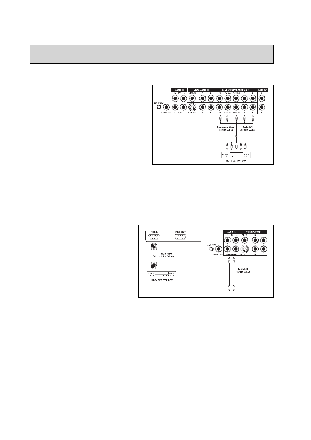
Connecting a HDTV Decoder Set-Top Box
Using Component Video Input
1.Connect the green (labeled as “Y”) jack from the
HDTV Set-top box to the green “Y1” jack of the
display.
2.Connect the red (labed as “PR” or “CR”) jack from
the HDTV Set-top box to the red “PR1/CR1” jack of
the display.
3.Connect the blue (labed as “PB” or “CB”) jack from
the HDTV Set-top box to the blue “PB1/CB1” jack of
the display.
4.Connect the red (R) and white (L) audio jacks from
the HDTV Set-top box to the R and L audio-in jacks
located next to the “PR1/CR1” connector.
Note:
! Some HDTV Set-top boxes may not have a Compo-
nent Video output. Instead, use RGB input method.
! There are two sets of component inputs provided.
You can use either set of component inputs to
connect your HDTV Set-top box.
Using RGB Input
1.Connect the 15-pin D-Sub RGB connector
from the back of the HDTV Set-top box to
the RGB-IN Connector located on the back
of the display.
2.Connect the red (R) and white (L) audio-out
jacks from the HDTV Set-top box to the R
and L audio-in jacks located to the left of
the S-VIDEO 1 connector.
Note:
! Some HDTV Set-top boxes may not have a
RGB output. Use Component Video input
method if this is the case.
! Upon connecting your HDTV Set-top box to
the RGB input of the display, it may be
necessary to adjust various picture settings
on the display to correctly match the output
of the HDTV Set-top box (see page 27).
This is caused by the different video timings
set by various HDTV Set-top box
manufacturers.
10
Page 14
CONNECTING THE DISPLAY
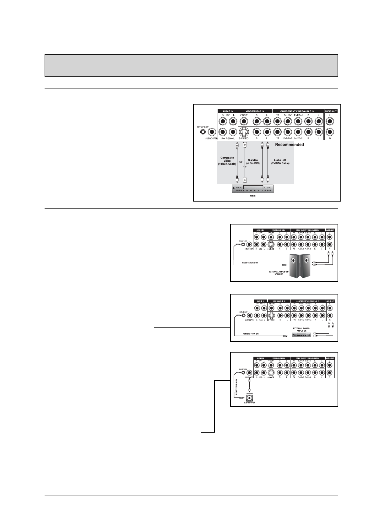
Connecting a VCR
Using S-Video Input
1.Connect the S-Video (4-pin DIN) connector from the
VCR to the “S-VIDEO 1” input on the back of
display.
2.Connect the red (R) and white (L) audio jacks from
the VCR to the R and L audio-in jacks located next
to the S-VIDEO 1 connector.
Using Composite Input
1.Connect the “yellow” (video) out connector from the
VCR to the yellow “Video 1” input on the back of
display.
2.Connect the red (R) and white (L) audio-out jacks
from the VCR to the R and L audio-in jacks located
next to the yellow “Video 1” connector.
External Audio Connections
Connecting External Amplified Speakers
1.This display can be connected to an external set of amplified
speakers using the AUDIO OUT jacks located on the back of the
display. In addition, this display is equipped with a small 3.5
mm phono style plug for remote turn-on applications that will
automatically send a remote turn-on/off signal to the external
amplified speakers.
2.Connect the red (R) and white (L) AUDIO OUT jacks from right
side of the connector panel to the external amplified speaker.
3.As an option, you may use the remote turn-on plug.
Please note that not all external amplified speakers can
accept remote-turn on signals.
Connecting to an External Amplifier
1.This display can be connected to an external amplifier
using the AUDIO OUT jacks located on the back of the
display. In addition, this display is equipped with a
small 3.5 mm phono style plug for remote turn-on
applications that will automatically send a remote turnon/off signal to the external amplifier.
2.Connect the red (R) and white (L) AUDIO OUT jacks
from right side of the connector panel to the external
amplifier or receiver.
3.As an option, you may use the remote turn-on plug.
Please note that not all external amplifiers can accept
remote-turn on signals.
Using the Subwoofer Out (Connecting a Subwoofer)
1.This display is equipped with a subwoofer output for
connecting to an external amplified subwoofer.
2.Connect a RCA cable from the subwoofer output jack to
the external subwoofer.
Notes:
! The AUDIO OUT RCA jacks can be set to either Fixed
or V ariable audio output levels. Please see page 23 for
additional explanation of this feature.
! The RCA subwoofer outputs frequen-
cies below 120Hz. The subwoofer will
use the same Fixed or Variable audio
output setting as AUDIO OUT RCA
jacks.
! The 3.5mm phono/earphone output
level is always used for remote turn
on/off applications.
11
Page 15
CONNECTING THE DISPLAY
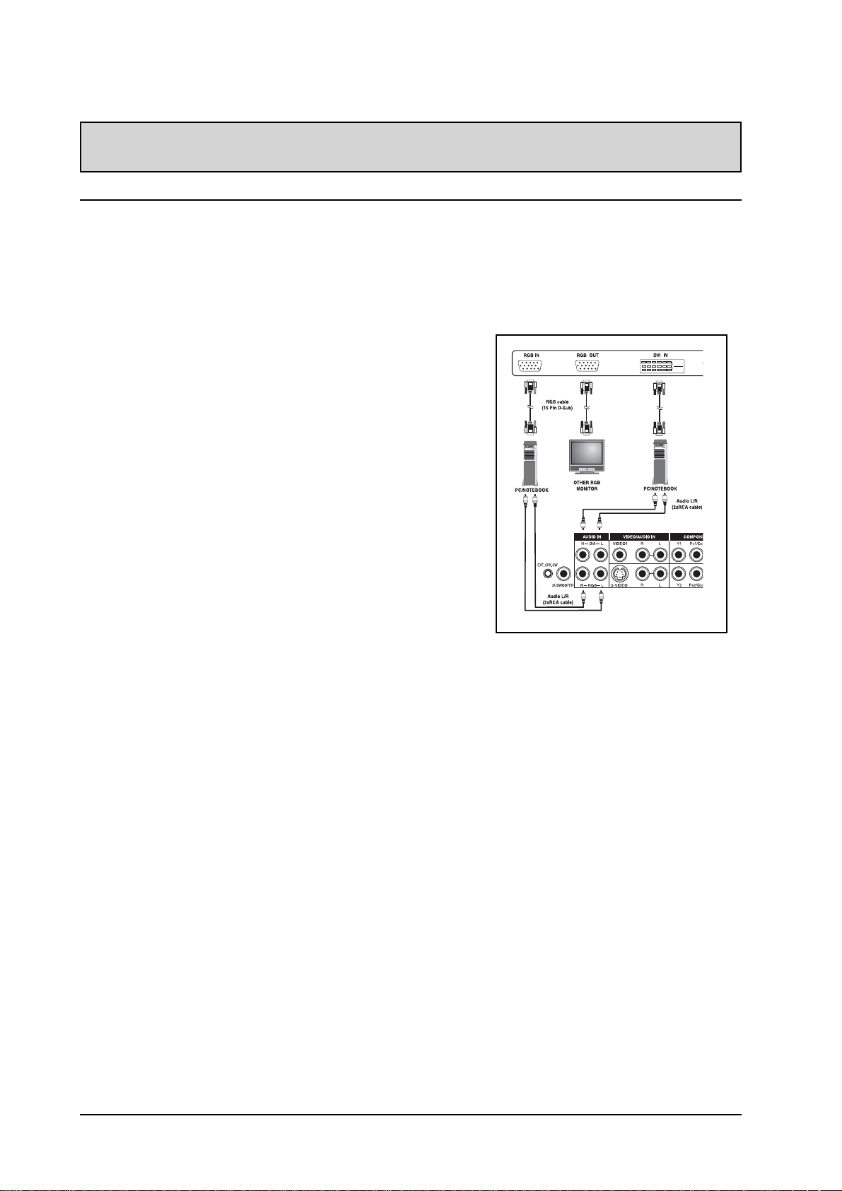
Connecting a PC
Using RGB or DVI Video Input
1.For most PC’s, connect the 15-pin D-Sub RGB connector from
the back of the PC to the RGB-IN Connector located on the
back of the display. If you have a PC that is equipped with a
DVI (Digital Visual Interface), you may connect the PC DVI
connector from the back of the PC to the DVI-In Connector
located on the back of the display.
2.Connect the red (R) and white (L) audio jacks from the PC to
the R and L jacks located to the left of the S-VIDEO 1
connector. If you are using a DVI interface, simply connect
the (R) and (L) audio jacks to the R and L jacks located to the
left of the VIDEO 1 connector.
Notes:
! Your PC may have audio jacks in the form of a 3.5mm phono
plug. If this is the case, you will need to use a phono-plug to
RCA converter cable in order to connect audio.
! A RGB loop-out labeled “RGB Out” will allow another RGB
display to be connected. The RGB loop-out will display the
same signal as the RGB In signal source.
! The physcial display resolution is a maximum of 640x480 dots
when aspect ratio is set to “4:3”, and 852x480 dots when set
to “16:9”. If the PC’s display resolution exceeds these
maximums, the display will have to artificially eliminate dots in
order to fit within the physical dot capability of the display;
therefore, it is possible that the display may not be able to
show details with adequate clarity.
12
Page 16
CONNECTING THE DISPLAY
RS-232 Remote Control Connections
RS-232 Serial Terminal Overview
This display is equipped with an RS-232 serial terminal for using the display with computer controls. The
RS-232 serial terminal conforms to the RS-232C interface specification. The computer will require software
application (such as programming language software) which allows the computer to send and receive control
data that can support the communications parameter listed below.
Communications Parameters
These parameters are required to setup communica-
tions with the display.
Specification RS-232C
Sync Method Synchronous
Baud Rate 9600 bps
Parity None
Character Length 8 Bits
Stop Bit 1 Bits
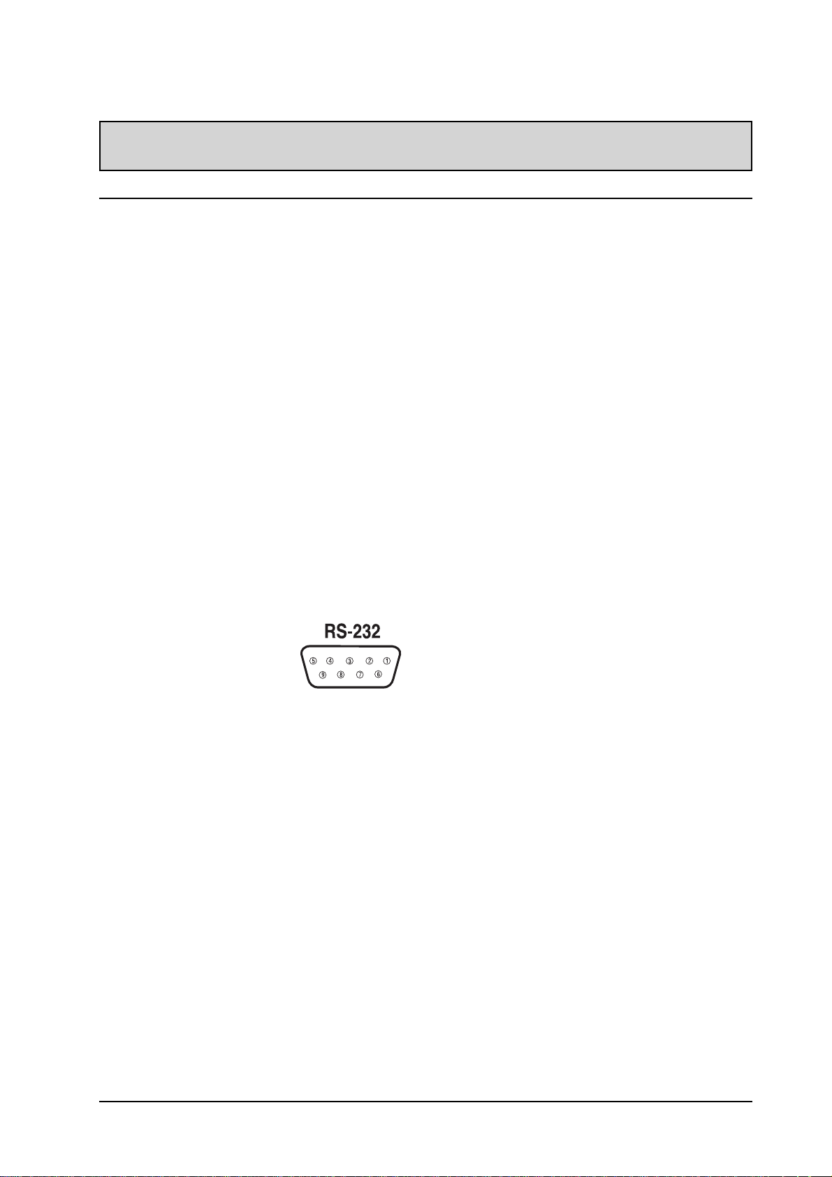
Pin Layout for RS-232 T erminal
The RS-232C terminal pin layout are as follows:
Pin 1 Received Line Signal Detector (Data Carrier
Detect)
Pin 2 Received Data (RXD)
Pin 3 Transmit Data (TXD)
Pin 4 Data T erminal Ready (DTR)
Pin 5 Signal Ground
Pin 6 Data Set Ready (DSR)
Pin 7 Request T o Send (RTS)
Pin 8 Clear T o Send (CTS)
Pin 9 Ring Indicator
Command Parameters
These remote control commands are available to
send to the display using RS-232.
Item Cmd Data Details
Read 80 81-A7 Reads the displays current
settings for command 81
thru A7
Volume 81 01-64H Set between 01-64H
Power On/Off 83 00-01 00=Off 01=On
Brightness 85 01-64H
Contrast 86 01-64H
V-Size 87 01-64H
V-Position 88 01-64H
H-Size 89 01-64H
H-Position 8A 01-64H
Color 8E 01-64H
Tint 8F 01-64H
Sharpness 90 01-64H
Input Select 91 00-07 01=AV1, 02=AV2, 03=AV3,
04=Component 1, 05=Com-
ponent 2, 06=RGB, 07=DVI
Recall 92 00 00=Initiate recall
Mute On/Off 95 00-01 00=Off 01=On
PanelKey Lock96 00-01 00=Off 01=On
Basic Format for Command Parameters
In order to transmit data from the computer to the
display, the data must be sent in 1-byte-hex format.
The command code (see table below) must first be
sent to the display, followed by the desired value
setting in hexadecimal format. The following is an
example of a sequence to change the displays input
to RGB:
Step 1: Send 1-byte for command 91 (input select) to
the display in hex format 0x91
Step 2: Send 1-byte for the value of the RGB input.
In this example, send 0x06.
Step 3: The display will then respond back to the PC
with a 1-byte value to confirm the setting.
Notes:
! If there are no data to be sent, then the param-
eter signal does not need to be sent.
! If multiple commands are transmitted, make sure
to wait for the response for the first command to
come from the display before sending the next
command. The following are response command
signals:
RESPONSE: 80 70 = MODE ERROR
80 71 = ITEM ERROR
80 72 = FORMA T ERROR
Item Cmd Data Details
Language 97 00-02 00=English, 01=French,
02=Spanish
Color T emp 98 00-03 00=High, 01=Mid, 02=Low,
03=6500D
Bass 9 A 01-64H
Treble 9B 01-64H
Balance 9C 01-64H
Woofer 9D 00-01 00=Off 01=On
BBE 9E 00-01 00=Off 01=On
Surround 9F 00-02 00=Off, 01=3D Stereo,
02=3D Mono
Zoom A5 00-05 00=16:9, 01=Panorama,
02=4:3, 03=Zoom1,
04=Zoom 2, 05=Zoom3
PIP/POP A7 00-03 00=Normal, 01=PIP,
02=POP1, 03=POP2 (4:3),
04=POP3 (16:9)
13
Page 17
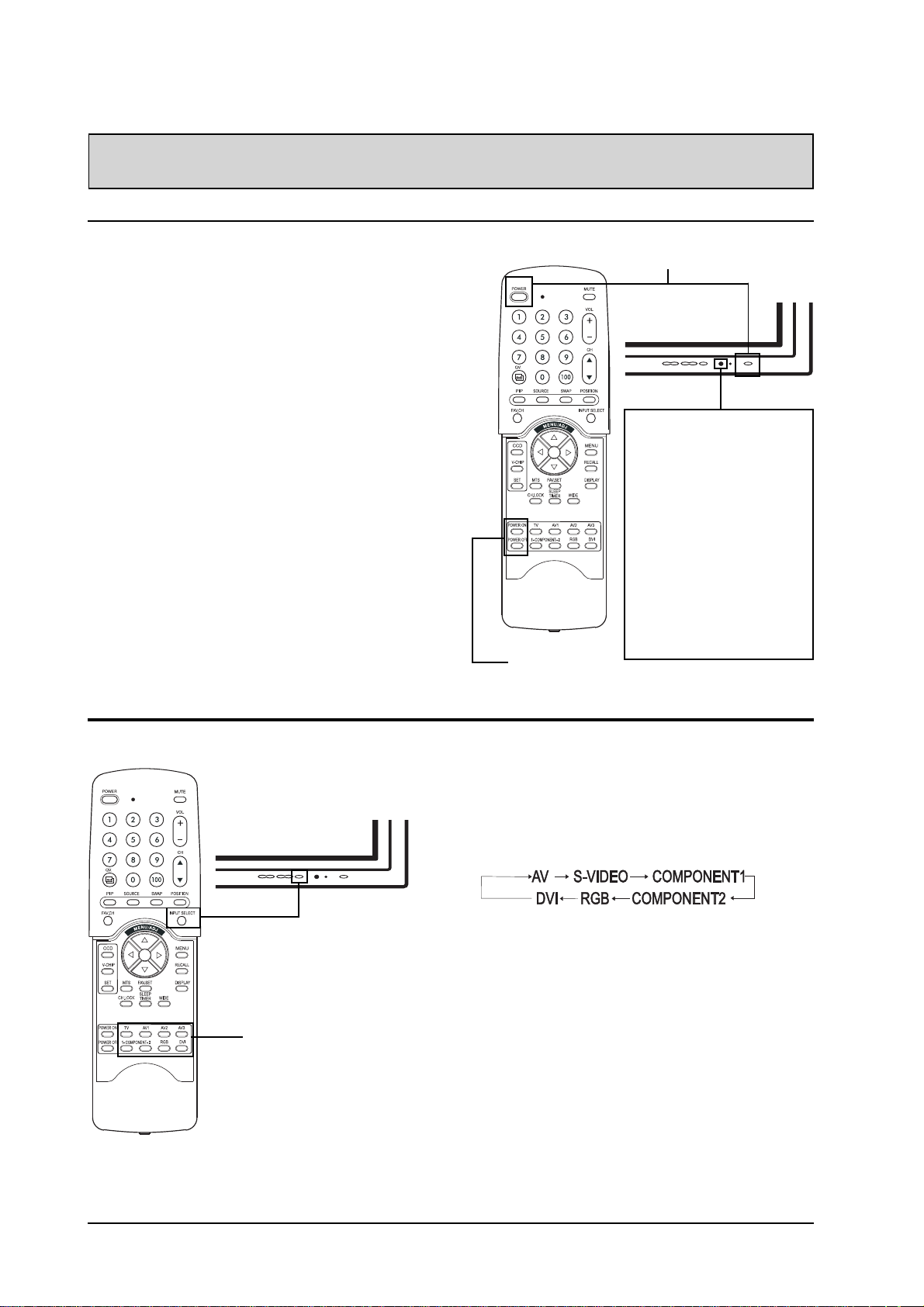
USING THE MONITOR - BASICS
Powering ON / OFF
Using Front Panel or Remote Control
1. Make sure the monitor is plugged into the wall
outlet and the main AC switch located in the
rear of the monitor is switched to ON position.
If the power is plugged in and the AC switch is
on, the STATUS LED will illuminate in solid
yellow color.
2. Press the POWER button on the front panel or
the remote control.
3. The monitor will now turn on after a brief pause.
The ST A TUS LED will now turn green to indicate
power on status.
4. To turn power off, simply press the POWER
button on the front panel or the remote control
once again.
Using Discrete Power ON/OFF Keys
1. The discrete POWER ON/OFF keys sends two
discrete signals to the monitor.
2. To turn power on, simply press the POWER ON
button. If the monitor is turned on already,
pressing this button will have no effect.
3. To turn off power, simply press the POWER
OFF button. If the monitor is already turned off,
pressing this button will have no effect.
POWER ON/OFF
Discrete
POWER (T oggle)
Status LED
!!
! Not Illuminated - No AC
!!
Power detected
If the main power switch
(rear of panel) is turned
off, this LED will not
illuminate.
!!
! Solid Yellow - Standby
!!
(Power OFF) with AC
power detected
The LED will illuminate in
yellow color if the monitor
is shut-off but the main
power cord is plugged into
the back of the unit.
!!
! Solid Green - Power ON
!!
Selecting Signal Source
Input Select
(Toggle)
Direct Input
Selection Keys
Using Front Panel or Remote Control
1. Press the INPUT key on the front panel or the
INPUT SELECT key on the remote control.
2. Pressing the INPUT key will cycle the monitor
thru all available input signal sources in the
following order:
Using Direct Input Selection Keys
1. If you prefer not to cycle thru all available inputs,
you can use the Direct Input Selection keys
located towards the bottom of the remote control.
2. Simply select the input that you would like to
switch to and press the Direct Input Selection
key for that input.
Notes:
! Some of the Direct Input Selection keys will not
be applicable for this monitor.
For A V mode, use AV1.
For S-Video, use AV2.
14
Page 18
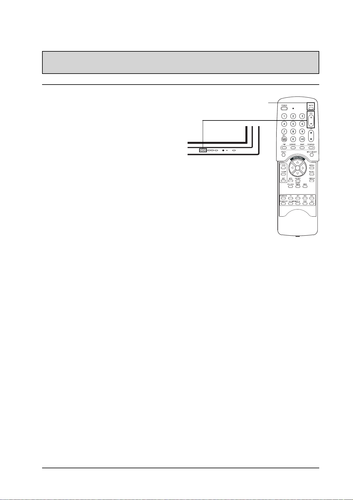
USING YOUR MONITOR - BASICS
Adjusting Sound Volume
Using Front Panel or Remote Control
1. To turn up sound volume, press VOLUME + on
either the front panel of monitor or on the remote
control.
2. T o turn down sound volume, press VOLUME - on
either the front panel of monitor or on the remote
control.
Using MUTE
1. If you would like to silence the volume on a
temporary basis, simply press the MUTE key to
silence the volume.
2. When the monitor’s volume is muted, the monitor
will display “MUTE” on the upper right corner of
the screen.
3. To disengage the mute mode, simply press the
MUTE key or the VOLUME +/- button again.
Notes:
! If the monitor’s built-in speakers are turned off
using the OSD, then volume controls will not
affect volume generated by the built-in speaker.
! Volume controls are valid when audio output is set
to “variable” (See page 23). If audio output is set
to “fixed”, then volume control is not active.
MUTE
VOLUME +/-
15
Page 19
USING WITH HDTV
Understanding HDTV
What is Digital Television or DTV?
Digital TVs are televisions that can receive and display digital television broadcasts sent using any one of
three following categories: HDTV (High Definition TV), EDTV (Enhanced Digital TV), and SDTV (Standard
Definition TV).
What is the Difference Between HDTV, EDTV, and SDTV?
HDTV, EDTV, and SDTV are three grades of televison or monitors. They reference the maximum resolution
capability of a digital television or monitor to fully display digital broadcasts without having to “down-convert”
the actual signal content to fit the monitor’s display limitations. The resolution requirements for each of the
three DTV classifications and an explanation of the specifications are described below:
Vertical Res.
1
Horizontal Res.2Aspect Ratio
3
Scan Method
4
1080 lines 1920 dots 16:9 Wide Interlaced
720 lines 1280 dots 16:9 Wide Progressive
HDTV grade televisions and monitors are capable of displaying a maximum of either
1080 lines using interlaced scan method or 720 lines using progressive scan method.
Vertical Res.
1
Horizontal Res.2Aspect Ratio
3
Scan Method
4
480 lines 640 dots 4:3 Progressive
EDTV grade televisions and monitors are capable of displaying a maximum of 480 lines
using progressive scan method. All resolutions higher than 480 lines must be reduced
to 480 lines in order to be displayed. Progressive scan method reduces flicker;
however, picture quality may not necessarily outperform 480 interlaced when viewed at
normal viewing distances.
Vertical Res.
1
Horizontal Res.2Aspect Ratio
3
Scan Method
4
480 lines 640 dots 4:3 Interlaced
SDTV grade televisions and monitors are capable of displaying a maximum of 480
lines using interlaced scan method. All resolutions higher than 480 lines must be
reduced to 480 lines in order to be displayed.
1
Vertical Resolution (Scan Lines)
Vertical scan lines refer to the number of horizontal lines a TV or monitor can display to create an image.
As the number of lines increase, more information is displayed, resulting in better picture quality.
2
Horizontal Resolution
Each horizontal line in a TV or monitor is made up of individual dots (pixels). The higher the number of
pixels, the finer the TV picture becomes. Horizontal pixel measurements using today's technology can
range from 250 for a VCR to as much as 500 for a DVD player.
3
Aspect Ratio
Aspect ratio identifies the ratio of the TV screen's width over its height. A 16:9 aspect ratio refers to a
wide-screen picture format, while a 4:3 refers to a standard “square” TV format.
4
Scan Mode
Interlaced scanning is a method that creates a TV picture with alternating lines of information and is the
cause for flickering. Progressive scanning is a method that creates a TV picture with consecutive lines
of information that results in flicker-free picture quality.
16
Page 20

USING WITH HDTV
How is a HDTV/EDTV/SDTV Different from a HDTV/EDTV/SDTV Monitor?
In order to receive digital broadcasts, a digital “receiver” or “decoder” must be used to receive and decode
digital broadcast signals. Digital decoders can be built into the display itself or they may come in the form
of a set-top box that is added separately to the display. HDTV/EDTV/SDTV Monitors are digital monitors
without a digital decoder built into the television whereas HDTV/EDTV/SDTV T elevisions are displays with a
decoder built-in. HDTV/EDTV/SDTV Monitors give you the flexibility to add a digital decoder in the future
when digital broadcasts are more prevalent.
What is "Down-Convert"?
Down-convert takes place when a digital broadcast signal exceeds the display capabilities of the display
and the broadcast signal is reduced to match the television's limited display capabilities. For example, if a
TV station broadcasts a digital program using 1080 lines (1080i format) while the display can only display
480 lines, the signal is reduced or down-converted to only 480 lines, resulting in lesser information being
displayed.
This plasma monitor is qualified as an EDTV Monitor. This means that this monitor can display up
to 480 lines using progessive scan format; therefore resolutions higher than 480 lines must be
down-converted in order to be displayed. This EDTV Monitor includes advanced digital processing circuitry where the down-conversion process is done automatically while maximizing picture
quality.
What is "Up-Convert"?
Up-convert takes place when a digital television's display capabilities exceed the digital broadcast signal
and the broadcast signal is increased to match the TV's display capabilities. For example, if a TV station
broadcasts a digital program using 480 lines and the digital television is able to display 1080 lines, the
signal is increased or “up-converted” to match the TV.
This monitor includes advanced digital processing where all traditional analog television and
video formats (NTSC / P AL) in the form interlaced signals are up-converted to 480 lines progressive
scan method. Please note that up-conversion may result in some picture artificacts because
information is being artificially added to the picture.
Is This Plasma Monitor Compatible with Digital TV / HDTV?
This plasma monitor is compatible with digital TV. In order to receive digital television broadcasts, you will
need to use a “HDTV decoder” or “HDTV set-top box” with component video output or RGB video output.
Please consult your local sales representative prior to purchasing a HDTV decoder or HDTV set-top box.
17
Page 21
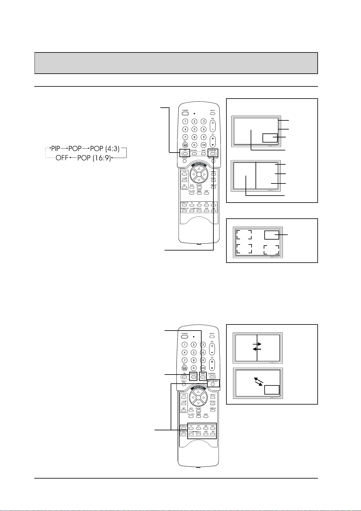
ADVANCED FUNCTIONS
Picture-In-Picture (PIP) / Side-by-Side Picture (POP)
Turn On PIP or POP Mode
1. Press the PIP key once on the remote
control to engage in PIP mode. Pressing the
PIP again will switch to POP mode. Pressing the PIP key sequentially will cycle
between:
2. When engaged in PIP mode, a small window
is displayed in one of the four corners. The
OSD on the upper right corner will denote the
input selected for main picture (large screen)
and the sub-picture (small screen) displayed.
3. If switched to POP mode, the screen will be
split in half. The screen on the left side is
the main picture and the screen on the right
is the sub-picture. The OSD on the upper
right corner will denote the input signal
source for both the main and sub-pictures.
PIP Mode
POP Mode
Sub-Picture Positions
M:AV1
S: AV2
M:AV1
S: AV2
Input Source for
Main Picture
Input Source for
Sub Picture
Sub
Picture
Main
Picture
Input Source for
Main Picture
Input Source for
Sub Picture
Sub
Picture
Main
Picture
Position 1
(Default)
Changing the Sub-Picture Position in PIP
Mode
1. Once the PIP mode is turned on, you can
switch the PIP sub-picture position to any
one of the four corners of the screen.
2. Press the POSITION key to switch position.
Pressing the POSITION key repeatedly will
cycle through all four corners of the screen.
3. This function is not applicable under POP
mode.
Switching Main and Sub-Pictures (SWAP)
1. Y ou can swap the main picture and subpicture using the SWAP key. Press the
SWAP key once to swap. Press the SWAP
key again to switch back.
Changing the Input Source for Sub-Picture
1. Once the PIP or POP mode is turned on, you
can change the sub-picture’s input source by
pressing the SOURCE key.
2. Pressing the SOURCE key repeatedly will
cycle through all available inputs for the subpicture.
Notes:
1. POP (4:3) Mode will preserve 4:3 aspect ratio for
both images displayed in the POP windows.
2. POP (16:9) Mode will preserve 16:9 aspect ratio for
both images displayed in the POP windows.
Swapping
Main
Picture
Main
Picture
Sub
Picture
Sub
Picture
Changing the Input Source for Main Picture
1. Once the PIP or POP mode is turned on, you
can change the main picture’s input source
by pressing the INPUT SELECT key or any
one of the DIRECT INPUT KEYS.
18
All PIP and POP related
settings are also accessible
using the on-screen Menu
display. Please see page 19
for details.
Page 22
ADVANCED FUNCTIONS
Picture-In-Picture (PIP) / Side-by-Side Picture (POP) - Con’t
Notes:
! PIP mode can only be turned on if the monitor’s input is set to: AV, S-Video, Component 1and 2. If the
monitor’s main input is set to RGB or DVI, the PIP and POP will not function.
! If the monitor’s input is set to Component 1 or Component 2, the PIP will only turn on if the input signal
source is compatible with 15 kHz signals such as 480i and Y/CB/CR signals.
! When changing input source for sub-pictures to Component 1 and Component 2, only 15 kHz compat-
ible signals such as 480i and Y/CB/CR will result in a video picture display. If another signal other than
15KHz is detected, the sub-picture may display distorted video signals.
! Once PIP is turned off, the next time you return on PIP mode, the position of the sub-window will start
at default position.
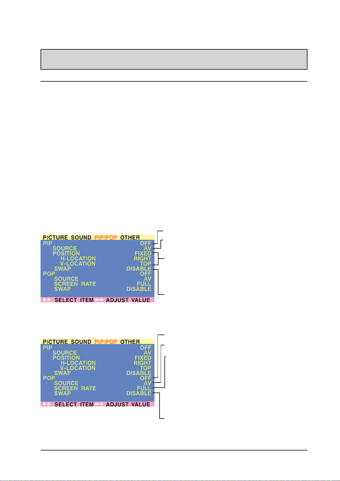
Accessing PIP and POP Modes Modes using OSD
You can also use the OSD menu to access the same PIP and POP mode functions. To access these
modes using OSD:
1. Press the MENU +/- keys on the remote or the front control panel.
2. Use the ADJ +/- keys to switch to “PIP/POP” Menu.
3. Make sure that the “Picture” OSD menu below is displayed.
4. Use the MENU +/- keys to move up and down to choose the sub-category you wish to change.
5. Use the ADJ +/- keys to actually change the setting.
PIP On/Off
Input Source Selection
PIP Window Position
1. Choose between FIXED or VARIABLE windows position.
2. If set to FIXED, the PIP window can be set in any one of the four
corners of the screen. Use H-LOCATION and V-LOCATION to set
the position of the window.
3. If set to VARIABLE, the PIP window can be variably set to
anywhere on the screen using H-LOCATION and V-LOCATION.
PIP Window SWAP
1. By default, the OSD will always display DISABLE. To swap the
main and sub windows, use the ADJ +/- key to swith to ENABLE.
Once the swap is complete, the OSD will return to display
DISABLE.
POP On/Off
Input Source Selection
Screen Rate (Aspect Ratio Control)
1. When POP (Side-by-side) picture is turned on, you can change
the aspect ratio for the image displayed.
2. Choose FULL to show a full screen image. The displayed image
may appear distorted because the monitor has to manipulate the
image so that it fits within the smaller window.
3. Choose 4:3 to show an image in native 4:3 aspect ratio within the
POP windows. Small black bars are added in order to maintain a
true 4:3 aspect ratio.
4. Choose 16:9 to show an image in wide-screen aspect ratio
within the POP windows. Small black bars are added in order to
maintain a true 16:9 aspect ratio.
PIP Window SWAP
1. By default, the OSD will always display DISABLE. To swap the
main (left) and sub (right) windows, use the ADJ +/- key to swith
to ENABLE. Once the swap is complete, the OSD will return to
display DISABLE.
19
Page 23
ADVANCED FUNCTIONS
Widescreen (16:9 Aspect Ratio) Viewing Modes
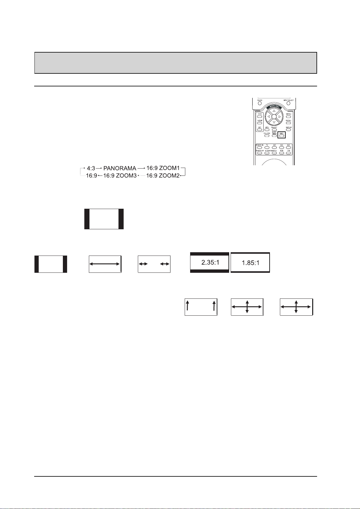
Understanding Widescreen Modes
This plasma monitor is capable of displaying a widescreen image on the
native 16:9 aspect ratio screen. However, not all available broadcast or
video content fits perfectly in a widescreen (16:9) format resulting in
unused screen space. Please use the following guidelines to determine
suitable widescreen viewing modes available that best support the type of
broadcast / video content you wish to display. All widescreen viewing
modes are available by pressing the WIDE key. Pressing the WIDE key
will repeatedly cycle through:
For 4:3 Aspect Ratio (Square) Content
Content from VCR, and some DVD’s are formatted
using a “square” 4:3 format:
Then we recommend the following three viewing
options:
4:3 (NORMAL)
In 4:3 mode, the
original 4:3
image is preserved but black
bars are added
to the the extra
space on the left
and right.
16:9 (FULL)
The original 4:3
image is proportionally stretched
to fill the entire
screen.
P ANORAMA
The original 4:3
image is
expanded in
both the
horizontal and
vertical
directions. The
center of the
picture is
almost normal
while the
endges are
considerably
expanded.
For Widescreen Content
Many popular DVD titles are “anamorphic”
(widescreen); however, there are two predominant
“anamorphic” (widescreen) asepct ratios: 2.35:1 and
1.85:1. When 2.35:1 content is displayed on this
16:9 widescreen monitor, you will notice smaller
black bars on top or bottom of the screen. When a
1.85:1 content is displayed, you will still see black
bars, but not as large as 2.35:1.
If you do not want to see the black bars when
playing back a widescreen movie, you can set to
ZOOM 2 or ZOOM 3 to fully stretch the image.
ZOOM: 1
Zoom1 shifts the
image up to
faciliate the
display of subtitles.
ZOOM: 2
Zoom 2 is set to
stretch 1.85:1
content to full
screen eliminating the black
bars.
ZOOM: 3
Zoom 3 is set to
stretch 2.35:1
content to full
screen eliminating the black
bars.
Notes:
1. 4:3 and Panorama modes are not available when zoom mode is engaged.
2. When using Component 1 and Component 2 inputs to display 480p, 1080i or 720p, Panorama mode is
not available.
3. When using RGB or DVI inputs, only 4:3 and 16:9 modes are available.
4. Do not stay in 4:3 mode for an extended period, as this may cause a permanent after-image to remain
on your screen.
20
Page 24
ADVANCED FUNCTIONS
Widescreen Viewing Modes (Con’t)
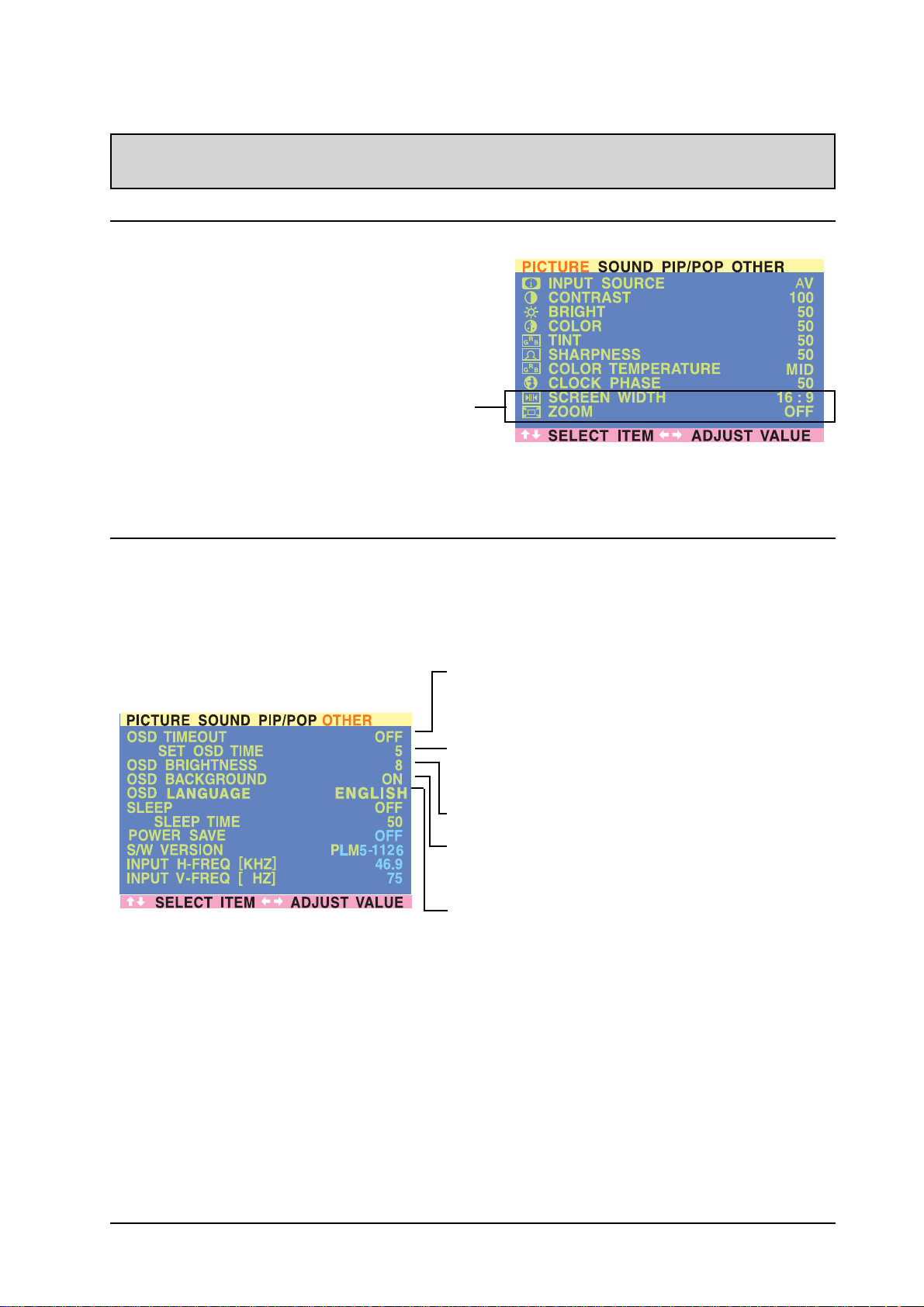
Accessing Widescreen Viewing Modes using OSD
You can also use the OSD menu to access the same
widescreen and zoom mode functions. To access
these modes using OSD:
1. Press the MENU +/- keys on the remote or the
front control panel.
2. Make sure that the following “Picture” OSD menu
is displayed.
3. Use the MENU +/- keys to navigate to SCREEN
WIDTH and use the ADJ +/- keys to switch
between 4:3, 16:9 or P ANORAMA.
4. Use the MENU +/- keys to navigate to ZOOM and
use the ADJ +/- keys to switch between zoom 1,2
or 3. Please note that this function is not accessible unless the SCREEN WIDTH is set to “16:9”.
On-Screen Display (OSD) Settings
Accessing OSD Settings Menu
Y ou can set various OSD display settings from the OSD menu.
1. Press the MENU +/- keys on the remote or the front control panel.
2. Use the ADJ +/- keys to navigate to “OTHER” OSD sub-menu as displayed below.
OSD Timeout
Turns on OSD timer when set to ON. When set to ON, the OSD will
automatically disappear from the display if no key action is detected
for the set number of seconds. If set to OFF, then OSD will remain
on the screen.
OSD Time Setting
Sets the number of seconds the OSD will remain active on the
display before turning itself off. OSD TIMEOUT must be set to ON
for this setting to function.
OSD Brightness
Sets the brightness level of OSD screen between 1 and 10.
OSD Background
You can set the OSD menu’s background to transparent or with a
blue background. Set to OFF if you want a transparent setting. Set
to ON if you want a blue background.
OSD Language
You can set the OSD language to English, French or
Spanish.
Note:
To prevent permanent after-image, we strongly suggest setting the
“OSD TIMEOUT” to ON.
21
Page 25
ADVANCED FUNCTIONS
Sleep Timer Settings
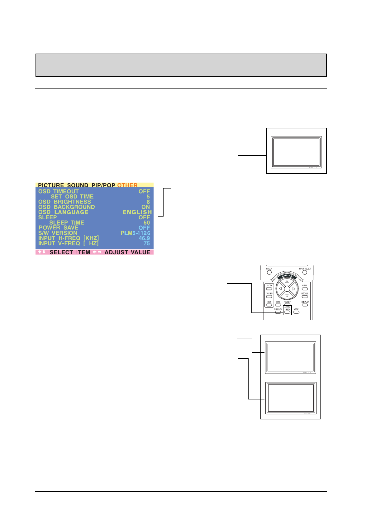
Setting Sleep Timer Using OSD
To set the sleep timer using the OSD screen:
1. Press the MENU +/- keys on the remote or the front control panel.
2. Use the ADJ +/- keys to navigate to “OTHER” OSD sub-menu as
displayed below.
3. Use the MENU +/- keys to navigate to SLEEP function.
4. Use the ADJ +/- keys to set to ON.
5. The monitor will function normally until the 1-minute mark. At the 1minute mark, the sleep timer will display a second by second countdown clock to notify that you that the monitor is about to turn off.
Sleep Timer On/Off
To turn on sleep timer,
switch to ON position. To
turn OFF sleep timer, switch
to OFF.
Timer Setting
You can set the turn-off
timer from 1 to 120 minutes.
Use the ADJ +/- keys to set
any number between 1 and
120.
Power Off Warning
SLEEP TIMER
0:59
Setting Sleep Timer Using Remote Control
To set the sleep timer using the remote control:
1. Press the SLEEP TIMER key on the remote. This will display the
sleep timer display on the upper right corner of screen.
2. Pressing the SLEEP TIMER key again will cycle the sleep timer
through all the preset times.
3. When setting is complete, simply press the DISPLA Y key to hide the
sleep timer display . Your sleep timer is now running in the
background.
4. The monitor will function normally until the 1-minute mark. At the 1minute mark, the sleep timer will display a second by second countdown clock to notify that you that the monitor is about to turn off.
5. If you wish to turn the sleep timer OFF before it shuts itself off, simply
press the SLEEP TIMER key again and cycle through all the preset
times until “SLEEP: OFF” is displayed.
Power Off Warning
SLEEP TIMER
Sleep Timer Set
SLEEP: OFF
0:59
22
Page 26
ADVANCED FUNCTIONS
Variable and Fixed Audio Output
Setting Output Using OSD
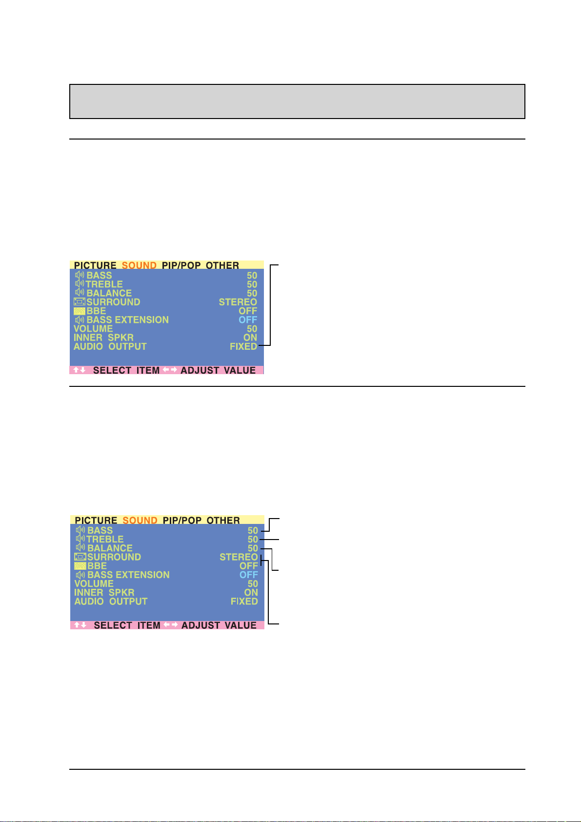
You can set the type of output this monitor outputs from its audio output jack located in the rear of the
monitor. By using an OSD based switch, you can easily choose between variable or fixed audio outputs.
To set the audio output setting:
1. Press the MENU +/- keys on the remote or the front control panel.
2. Use the ADJ +/- keys to navigate to “SOUND” OSD sub-menu.
3. Use the MENU +/- keys to select the AUDIO OUTPUT option.
4. Use the ADJ +/- keys to change setting between FIXED or V ARIABLE.
AUDIO OUTPUT
Sets the type of audio output sent from the audio output jacks
located in the rear of monitor.
!!
! VARIABLE
!!
When set to Variable, audio output is affected by the monitor’s
internal audio controls including bass, treble, surround, BBE,
bass extension, and volume.
!!
! FIXED
!!
When set to Fixed, the audio output bypasses the monitor’s
internal audio control so that functions such as bass, treble,
surround, BBE, bass extension, and volume controls have no
effect.
Sound Adjustments
Sound Adjustments Using OSD
Sound adjustments are available to enhance the sound performance of the monitor. These adjustments will
affect the monitor’s built-in speakers and the AUDIO OUTPUT jacks when set to “V ariable” (see above
section). To access sound adjustments:
1. Press the MENU +/- keys on the remote or the front control panel.
2. Use the ADJ +/- keys to navigate to “SOUND” OSD sub-menu.
3. Use the MENU +/- keys to select the various options described in this section.
BASS
Adjusts the BASS level of the sound. For more bass response,
increase the BASS level.
TREBLE
Adjusts the TREBLE level of the sound. For more vocal and high
frequency response, increase the TREBLE level.
BALANCE
Adjusts the BALANCE level between LEFT and RIGHT channels. A
value of 50 is the center point between LEFT and RIGHT. To shift
the sound towards the RIGHT, increase the value up to 100. To
shift the sound towards the LEFT, reduce the value down to 1.
SRS® Surround Sound and BBE® Sound
This monitor is equipped with SRS® Surround Sound and BBE
Sound Maximizer circuitry. Use SRS Surround Sound to simulate a
surround sound effect if you are not using a multi-channel sound
setup. Use the BBE Sound Maximizer when using the monitor to
playback live performance related audio programs.
®
23
Page 27
ADVANCED FUNCTIONS
Sound Adjustments (Con’t)
Switching OFF Built-In Speakers
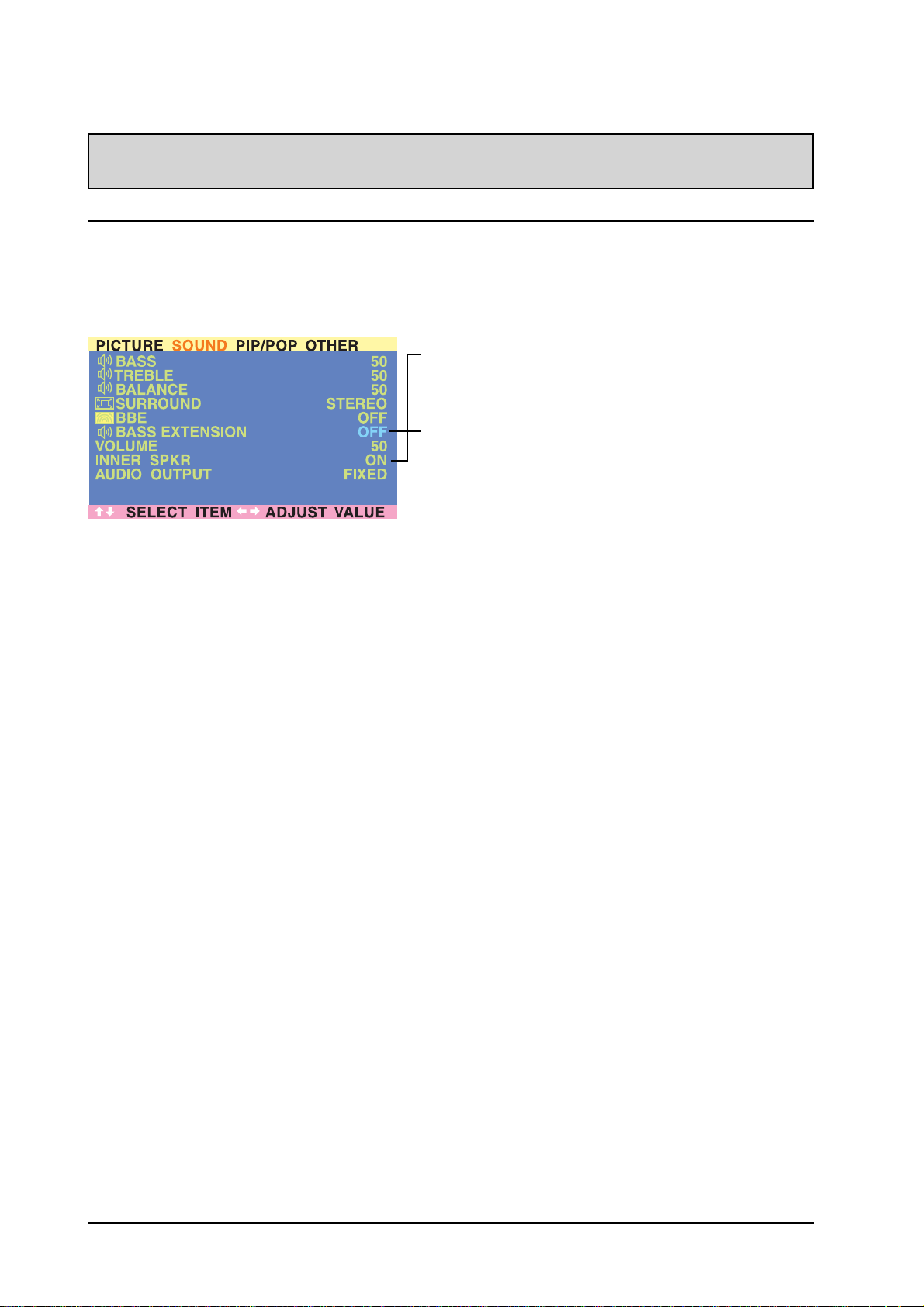
This monitor is equipped with built-in speakers. You can switch the internal speakers ON or OFF using the
OSD. Because these speakers are general purpose, you may consider switching them OFF during hifidelity playback of movies or other content.
INNER SPEAKER ON/OFF
Set to ON to turn on the monitors internal speakers. Set to OFF to
turn off internal speakers. This setting will not affect AUDIO
OUTPUT jacks.
BASS EXTENSION
Bass extension extends the level of BASS output by the monitor.
This function is automatically set to OFF if the INNER SPKR is turned
ON to protect the internal speaker from damage. This function will
affect the BASS performance only through AUDIO OUTPUT jacks
and when the AUDIO OUTPUT setting is set to VARIABLE.
24
Page 28
ADVANCED FUNCTIONS
Signal Frequency Information Display
Displaying Frequency of Signal
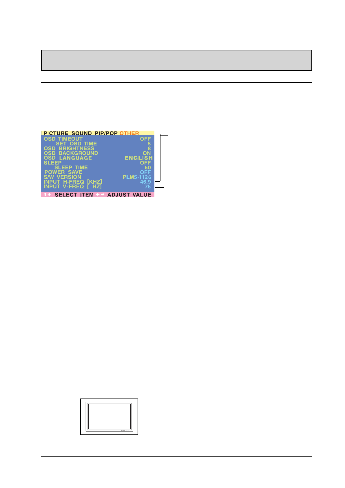
This monitor is capable of displaying the frequency level of the signal being displayed. To see signal
frequency information:
1. Press the MENU +/- keys on the remote or the front control panel.
2. Use the ADJ +/- keys to navigate to the “OTHER” OSD sub-menu.
INPUT H-FREQ (kHZ)
Displays the horizontal signal frequency of the signal currently
displayed. Please use the frequency cross reference tables below
to see which type of signal is being displayed under various input
modes.
INPUT V-FREQ (HZ)
Displays the vertical signal frequency of the signal currently
displayed. Please use the frequency cross reference tables below
to see which type of signal is being displayed under various input
modes.
When Using AV1 and AV2 Inputs
Horizontal Vertical Format
15.7 60 NTSC Video
15.6 50 P AL Video
When Using Component 1 & 2 Inputs
Horizontal Vertical Format
15.7 60 NTSC Video
15.6 50 P AL Video
15.7 60 480i (SDTV)
31.5 60 480p (EDTV)
31.25 50 576p (EDTV)
28.125 50 1080i (HDTV)
33.0 60 1080i (HDTV)
45.0 60 720p (HDTV)
When Using RGB & DVI Inputs
Mode Horizontal Vertical Format Refresh rate
1 31.500 59.940 640×480 (VGA) 60
2 37.900 72.810 640×480 (VGA) 72
3 37.500 75.000 640×480 (VGA) 75
4 43.300 85.010 640×480 (VGA) 85
5 35.100 56.250 800x600 (SVGA) 56
6 37.900 60.317 800x600 (SVGA) 60
7 48.100 72.190 800x600 (SVGA) 72
8 46.900 75.000 800x600 (SVGA) 75
9 53.700 85.060 800x600 (SVGA) 85
10 48.400 60.010 1024x768 (XGA) 60
1 1 56.500 70.070 1024x768 (XGA) 70
12 60.000 75.030 1024x768 (XGA) 75
13 68.700 84.900 1024x768 (XGA) 85
14 63.980 60.020 1280x1024 (SXGA) 60
15* 79.980 75.030 1280x1024 (SXGA) 75
16* 91.150 85.020 1280x1024 (SXGA) 85
18 31.460 70.080 720x400 (DOS) 70
19 31.500 50.000 640x480 (VGA) 50
20* 45.000 60.000 1280x720p (HDTV) 60
21* 33.750 60.000 1920x1080i (HDTV) 60(i)
22 31.500 70.000 640x350 (VGA) 70
23 31.410 59.835 852x480 (WVGA) 60
24 35.000 66.670 640x480 (Apple) 67
25 49.730 74.550 832x624 (Apple) 75
26 68.680 75.060 1152x870 (Apple) 7 5
RGB
M: 05
Notes:
1. When using RGB mode, the OSD will display a mode
number that references the table above.
2. Modes 15, 16, 20, and 21 are not available with DVI input.
3. Modes 24, 25 and 26 are for use with Apple Macintosh
computers.
25
Page 29
ADJUSTING PICTURE
For AV / Component Video
Accessing Picture Adjustment Mode
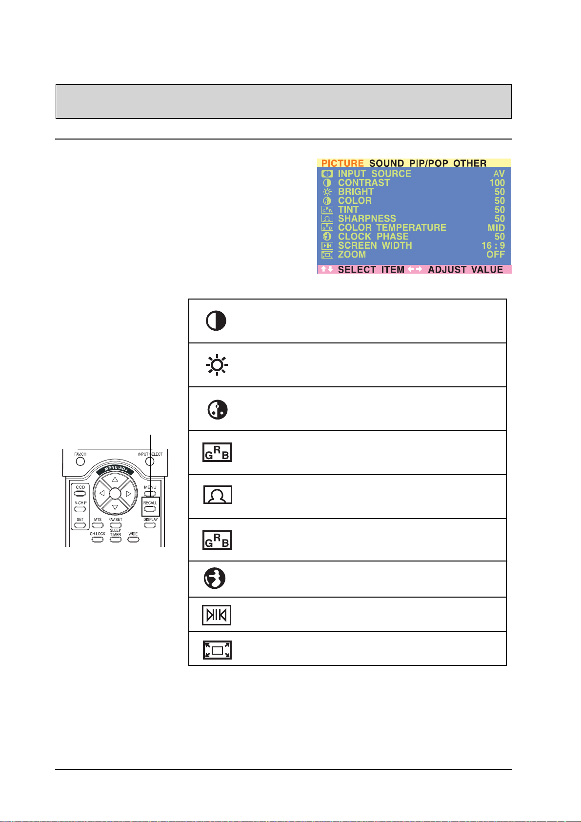
V arious picture adjustments can be set using the Picture
Adjustment OSD menu. To access the OSD menu:
1. Press the MENU +/- keys on the remote or the front
control panel.
2. The first menu displayed is the PICTURE menu. Make
sure that the “Picture” OSD menu is displayed.
3. Use the MENU +/- keys to move up and down to
choose the option you wish to adjust. An explanation
of each adjustment is listed below.
4. Use the ADJ +/- keys to change the setting.
Notes:
! These controls are
available when input
selection is set to: AV1,
A V2 (S), and Component 1 and Component 2
inputs.
! To restore picture
settings to the factory
defaults, simply press
the RECALL key from
the remote control.
CONTRAST
Adjust Contrast to increase the level of “white” in the video picture.
Increasing contrast will make white areas of the video picture brighter.
Contrast works in conjuction with BRIGHTNESS.
BRIGHTNESS
Adjust brightness to enhance the level of dark areas in the video picture
such as night scenes and shadow scenes. Increasing brightness will
make dark areas more visible.
COLOR
Use color to adjust the color saturation of the video picture. Increasing
color will make the color more intense. Reducing color setting will make
the color less intense.
TINT(For NTSC Only)
Use tint to adjust the color of fleshtones. Increasing the tint setting will
shift the picture with more cyan (more green appearance). Decreasing
the setting wil shift the picture with more magenta (more red appearance).
SHARPNESS
Use sharpness to adjust the amount of detail enhancement to the
video picture. Increase the setting will enhance the edges of objects
in the video picture. Decreasing the setting will reduce enhancement.
COLOR TEMPERATURE
Select the color temperature for white balance. There are four settings to
choose from: (1) LOW - sets to 7180K; (2) MID - sets to 8680K; (3) HIGH sets to 10180K
CLOCK PHASE
Use clock phase to fine-tune the monitor to perfectly synchronize the
video’s signal source. This function is not applicable in this mode.
SCREEN WIDTH
Use to change various screen width modes. See page 20 for more
information.
ZOOM
Use to change various digital zoom modes. See page 20 for more
information.
Notes:
1. Each of the (4) color temperature settings may not be exactly equal to the temperature setting as
defined; however, it will be approximately close.
26
Page 30
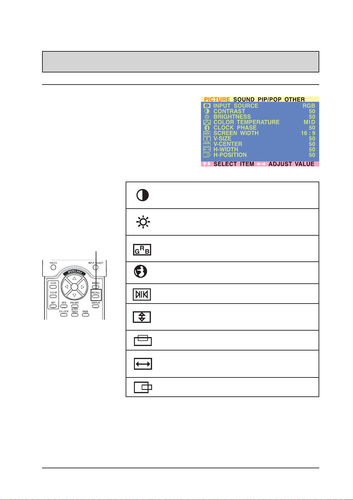
For RGB / DVI
Accessing Picture Adjustment Mode
V arious picture adjustments can be set using the Picture
Adjustment OSD menu. To access the OSD menu:
1. Press the MENU +/- keys on the remote or the front
control panel.
2. The first menu displayed is the PICTURE menu.
Make sure that the “Picture” OSD menu is displayed.
3. Use the MENU +/- keys to move up and down to
choose the option you wish to adjust. An explanation
of each adjustment is listed below.
4. Use the ADJ +/- keys to change the setting.
PICTURE ADJUSTMENT
Notes:
! These controls are
available when input
selection is set to: RGB
or DVI inputs.
! To restore picture
settings to the factory
defaults, simply press
the RECALL key from
the remote control.
CONTRAST
Adjust Contrast to increase the level of “white” in the video picture.
Increasing contrast will make white areas of the video picture brighter.
Contrast works in conjuction with BRIGHTNESS.
BRIGHTNESS
Adjust brightness to enhance the level of dark areas in the video picture
such as night scenes and shadow scenes. Increasing brightness will
make dark areas more visible.
COLOR TEMPERATURE
Select the color temperature for white balance. There are four settings to
choose from: (1) LOW - sets to 7180K; (2) MID - sets to 8680K; (3) HIGH sets to 10180K
CLOCK PHASE
Use clock phase to fine-tune the monitor to perfectly synchronize the
video’s signal source.
SCREEN WIDTH
Use to change various screen width modes. There are two selections
available: 16:9 and 4:3. Please see page 22 for more information.
V-SIZE
Use to change vertical size of the picture. Increase to enlarge the picture
size in the vertical direction. Decrease to reduce the picture size in the
vertical direction.
V-CENTER
Use to change vertical position of the picture. Increase to shift the picture
up. Decrease to shift the picture down.
H-WIDTH
Use to change horizontal size of the picture. Increase to enlarge the
picture size in the horizontal direction. Decrease to reduce the picture
size in the horizontal direction.
H-POSITION
Use to change horizontal position of the picture. Increase to shift the
picture to the right. Decrease to shift the picturn to the left.
Notes:
1. Each of the (4) color temperature settings may not be exactly equal to the temperature setting as
defined; however, it will be approximately close.
27
Page 31
TROUBLESHOOTING
Troubleshoot Common Conditions
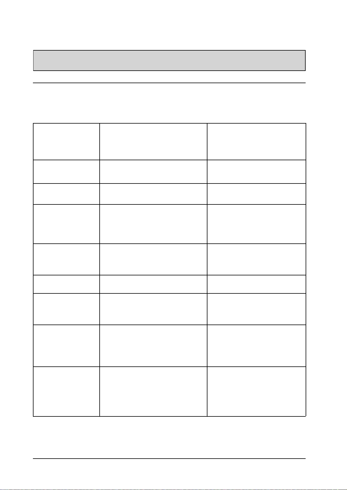
The following list represents possible anomalies that you may encounter and methods for remedy. Please
refer to this checklist prior to contacting a service representative.
Symptom
No picture is displayed 1. The power cord is disconnected.
Interference displayed on
the monitor or audible noise
is heard
Color is abnormal 1. The signal cable is not connected
Picture is distorted with
abnormal patterns
Display image doesn’t fill up
the full size of the screen
Can hear sound, but no
picture
Possible Cause Remedy
2. The main power switch on the back of the
monitor is not switched on.
3. The selected input has no connection.
4. The monitor is in standby mode in RGB
mode.
1. Caused by surrounding electrical
appliances, cars/motorcycles or fluores-
cent lights.
properly.
1. The signal cable is not connected
properly.
2. The input signal is beyond the capabilities
of the monitor.
1. If under RGB mode, the H-Size and V-Size
is incorrectly set.
2. If under AV1, AV2, or Component input,
the 4:3 WIDE mode is switched on.
1. Improperly connected source signal cable. 1. Make sure that both video inputs and
1. Plug in the power cord.
2. Make sure the power switch is
switched on.
3. Connect a signal connection to the
monitor.
4. Press any key on your keyboard.
1. Move the dispaly to another location to
see if the interference is reduced.
1. Make sure that the signal cable is
attached firmly to the back of the
monitor.
1. Make sure that the signal cable is
attached firmly.
2. Check the video signal source to see if
it is beyond the range of the monitor.
Please verify its specifications with
this monitor’s specification section.
1. Use H-Size and V-Size to adjust the
size of the video.
2. Use the WIDE key to scroll through
various full screen modes.
sound inputs are correctly connected.
Can see picture but no
sound is heard
Some picture elements do
not light up
After-Images can still be
seen on the monitor after
the monitor is powered off.
(Examples of still pictures
include logos, video games,
computer images, and
images displayed in 4:3
normal mode)
28
1. Improperly connected source signal cable.
2. Volume is turned all the way down.
3. MUTE is turned on.
1. Some pixels of the plasma display may not
turn on.
1. A still picture is displayed for an over
extended period of time.
1. Make sure that both video inputs and
sound inputs are correctly connected.
2. Use VOLUME +/- to hear sound.
3. Switch MUTE off by using the MUTE
button.
1. This monitor is manufactured using an
extremely high level of precision
technology; however, sometimes some
pixels of the monitor may not display.
This is not a malfuction. Please see the
enclosed warranty card for more
information.
1. Do not allow a still image to be
displayed for an extended period of
time as this can cause a permanent
after-image to remain on the monitor.
Page 32

SPECIFICATIONS
Display Panel
Screen size 42 ”
Aspect ratio 16:9
Number of pixels 852(Horizontal) x 480(Vertical) pixels
Pixel Pitch 1.08mm X 1.08mm
Luminance 1000cd/m2 (1/25 white window)
Power Source
Input voltage 100 ~ 240 V ac , 50 / 60 Hz
Input current 4A
Inrush current 60 A p-p/20ms Max.
Power consumption 390W Max ( at 110V ac/color bar pattern)
Stand-by & Power Save 10 Watts Max. (at 110V ac)
Connection
Connector Types RCA Jacks for audio, video, Y/CB/CR and Y/PB/PR
6 pin Din S-terminal for S-Video
9 pin D-SUB for RS232
15 pin D-SUB for RGB
24 pin DVI
Video/S-Video Signal
T y p e Analog
Polarity Positive
Amplitude d. Video 1Vp-p , (with sync), S-VideoY=1Vp-p C=0.286Vp-p
Frequency H: 15.734KHz V: 60Hz(NTSC)
H: 15.625KHz V: 50Hz(PAL)
Input impedance 75 ohms
Y/CB/CR or Y/PB/PR Signal (Component 1 & 2)
T y p e Analog
Polarity Positive
Amplitude Y: 1Vp-p (with sync)
CB/PB:0.7Vp-p CR/PR:0.7Vp-p
Frequency
Y/CB/CR H: 15.734KHz V: 60Hz (NTSC)
H: 15.625KHz V: 50Hz (PAL)
Y/PB/PR: HDTV H: 31KHz V: 60Hz (480p)
H: 31.25KHz V: 50Hz (576p)
H: 45KHz V: 60Hz (720p)
H: 33KHz V: 60Hz (1080i)
H: 28.125KHz V: 50Hz (1080i)
RGB Signal
Type TTL
Polarity Positive or Negative
Amplitude RGB: 0.7Vp-p
Frequency H: support to 31K~91KHz
V: support to 50~85Hz
DVI Signal
Type Digital
Polarity Positive or Negative
Frequency H: support to 31K~69KHz
V: support to 50~85Hz
Audio Signal Analog 500mV rms /more than 22Kohm
29
Page 33

SPECIFICATIONS
Pin Assignments For D-SUB connector (in / loop out)
Pin Signal Assignment Pin Signal Assignment Pin Signal Assignment
1 RED 6 RED GND 1 1 GND
2 GREEN 7 GREEN GND 1 2 SDA
3 BLUE 8 BLUE GND 13 H-SYNC
4 GND 9 NC 14 V-SYNC
5 GND 10 GND 15 SCL
Pin Assignments For 24 Pin DVI connector (digital only)
Pin Signal Assignment Pin Signal Assignment Pin Signal Assignment
1 TMDS Data 2- 9 TMDS Data 1- 17 TMDS Data 02 TMDS Data 2+ 10 TMDS Data 1+ 18 TMDS Data 0+
3 TMDS Data 2/4 Shield 11 TMDS Data 1/3 Shield 19 TMDS Data 0/5 Shield
4 TMDS Data 4- 12 TMDS Data 3- 20 TMDS Data 55 TMDS Data 4+ 13 TMDS Data 3+ 21 TMDS Data 5+
6 DDC Clock 1 4 +5V Power 22 TMDS Clock Shield
7 DDC Data 15 Ground (For +5V) 23 TMDS Clock +
8 No Connect 16 Hot Plug Detect 2 4 TMDS Clock -
RGB/DVI For VESA Standard
Refresh Horizontal Vertical V-Sync H-Sync
Mode Rate Frequency Frequency Polariy Polarity Dot rate
No. Resolution (Hz) (kHz) (Hz) (TTL) (TTL) (MHz)
1 640(VGA)×480 60 31.500 59.940 - - 25.175
2 640(VGA)×480 72 37.900 72.810 - - 31.500
3 640(VGA)×480 75 37.500 75.000 - - 31.500
4 640(VGA)×480 85 43.300 85.010 - - 36.000
5 800(SVGA)×600 56 35.100 56.250 + + 36.000
6 800(SVGA)×600 60 37.900 60.317 + + 40.000
7 800(SVGA)×600 72 48.100 72.190 + + 50.000
8 800(SVGA)×600 75 46.900 75.000 + + 49.500
9 800(SVGA)×600 85 53.700 85.060 + + 56.250
10 1024(XGA)×768 60 48.400 60.010 - - 65.000
1 1 1024(XGA)×768 70 56.500 70.070 - - 75.000
12 1024(XGA)×768 75 60.000 75.030 + + 78.750
13 1024(XGA)×768 85 68.700 84.990 + + 94.500
14 1280(SXGA)×1024 60 63.980 60.020 + + 108.00
15* 1280(SXGA)×1024 75 79.980 75.030 + + 135.00
16* 1280(SXGA)×1024 85 91.150 85.020 + + 157.50
18 720(DOS)×400 7 0 31.460 70.080 + - 28.322
19 640(VGA)×480 50 31.500 50.030 - - 25.175
20* 1280(HDTV)×720p 60 45.000 60.000 + + 74.250
21* 1920(HDTV)×1080i 60(i) 33.750 60.000 + + 74.250
22 640(VGA)×350 70 31.500 70.000 - + 25.175
23 852(WGA)×480 60 31.410 59.835 - - 30.000
24 640 × 480 67 35.000 66.670 - - 30.240
25 832 x 624 75 49.730 74.550 - - 57.283
26 1152 x 870 75 68.680 75.060 - - 100.000
Notes:
1. Modes 15, 16, 20, and 21 are not available with DVI input.
2. Modes 24, 25 and 26 are for use with Apple Macintosh computers.
30
Page 34

Y/PB/PR For Component 1 and 2
Mode Resolution Refresh Rate
1 640 × 480p 6 0
2 1920 ×1080i 60
3 1280 × 720p 6 0
Maximum Resolution Up to 1280 x 1024
Dimensions Without/Stand With/Stand
Width 1040 mm 1040 mm
Height 648 mm 690 mm
Depth 95 mm 287.5 mm
Package Dimensions
Width 1230 mm
Height 960 mm
Depth 470 mm
Weight
Net weight 68.8lbs/31.2 Kgs (w/o stand) 77.2lbs/ 35Kgs (w/ stand)
Gross weight 101.4lbs/46 Kgs
SPECIFICATIONS
Operating
Temperature 0~40oC (32~104oF)
Relative humidity 20~80%
Pressure 80 0 ~ 1114hpa
Non-Operating
Temperature -5~50oC
Relative humidity 20~90%
Pressure 60 0 ~ 1114hpa
Vibration X/Y/Z, 0.5G/10~55Hz(sweep), 10 minutes
Acoustics
(IHF A-weighted 1meter) 40dB Max.
Sound
Residual hum (at volume max) 500µW Max.
Practical max. Audio output (at 10% THD max.) 1.0vp-p 1K Hz input 5W +5W Max. /12 ohm
Sound distortion (at 250 mw 1K Hz) 1% M a x .
Audio output (input at 1.4V
Reliability Requirement
The MTBF is 20,000hrs. under operation 25±5o C (Half luminosity, motion picture)
) >=1.0 V
P-P
P-P
31
Page 35

SPECIFICATIONS
Emission Requirement
The unit meet the EMI limits in all screen modes as qualified by FCC class B part 15.
Power Management
Mode H-sync V-sync Video Power dissipation
Normal Pulse Pulse Active Normal power
Stand-by No pulse No pulse No video Power off
Power saving Pulse No pulse blanked Less than 10 watts
No pulse Pulse
This Plasma display is Energy star compliant when used with a computer equipped with DPMS.
32
Page 36
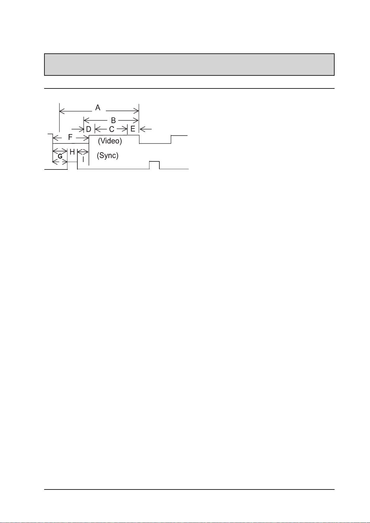
Preset Timing Chart
Item Description:
A Total time
B Active display area including borders
C Active display area excluding borders
D Left/Top border
E Right/bottom border
F Blanking time
G Front porch
H Sync-width
I Back porch
SPECIFICATIONS
Mode No 1 2 3 4 5 6 7 8 9
H Resolution 640 64 0 640 64 0 800 800 800 800 800
V Resolution 48 0 480 480 48 0 600 600 600 600 600
Refresh Rate 60 72 75 85 56 60 72 75 8 5 Hz
Pixel 25.175 31.500 31.500 36.000 36.000 40.000 50.000 49.500 56.250 MHz
Horizontal visible 640 640 640 640 800 800 800 800 800 Dots
Horizontal total 800 832 84 0 832 1024 1056 1040 1056 1048 Dots
Horizontal front porch 16 24 16 56 24 40 5 6 1 6 32 Dots
Horizontal sync 96 40 64 56 72 128 120 80 64 Dots
Horizontal back porch 48 128 120 80 12 8 88 6 4 160 152 Dots
Horiz blanking time 160 192 200 192 224 256 24 0 256 248 Dots
Vertical visible 480 480 480 480 600 600 600 600 600 Lines
Vertical total 525 520 500 50 9 62 5 628 66 6 625 631 Lines
Vertical front porch 1 0 9 1 1 1 1 37 1 1 Lines
Vertical sync 2 3 3 3 2 4 6 3 3 Lines
Vertical back porch 33 28 16 25 22 2 3 23 21 27 Lines
Vertical blanking time 45 40 2 0 29 25 2 8 66 25 31 Lines
Horizontal frequency 31.469 37.861 37.500 43.269 35.156 37.879 48.077 46.875 53.674 KHz
Vertical frequency 59.940 72.809 75.000 85.008 56.250 60.317 72.188 75.000 85.061 Hz
Vertical sync polarity - - - - +++++TTL
Horiz sync polarity - - - - +++++TTL
33
Page 37

SPECIFICATIONS
Mode No 10 1 1 12 13 14 15 16 18 19
H Resolution 1024 1024 1024 1024 1280 1280 1280 720 640
V Resolution 76 8 768 768 76 8 1024 1024 1024 400 480
Refresh Rate 60 70 75 85 60 75 85 70 50 Hz
Pixel Clock 65.000 75.000 78.750 94.500 108.000135.000157.50028.322 25.175 MHz
Horizontal visible 1024 1024 1024 1024 1280 1280 1280 720 640 Dots
Horizontal total 1344 1328 1312 1376 1688 1688 1728 900 800 Dots
Horizontal front porch 24 24 16 48 48 16 6 4 1 8 16 Dots
Horizontal sync 136 136 96 96 112 144 160 108 96 Dots
Horizontal back porch 16 0 14 4 176 208 248 248 224 54 48 Dots
Horiz blanking time 320 304 288 352 408 408 44 8 180 160 Dots
Vertical visible 768 768 768 76 8 1024 1024 1024 400 480 Lines
Vertical total 806 806 800 808 1066 1066 1072 449 629 Lines
Vertical front porch 3 3 1 1 1111262Lines
Vertical sync 6 6 3 3 33322Lines
Vertical back porch 29 29 28 36 38 3 8 44 35 85 Lines
Vertical blanking time 38 38 3 2 40 42 42 48 4 9 14 9 Lines
Horizontal frequency 48.364 56.476 60.023 68.677 63.981 79.976 91.146 31.469 31.469 KHz
Vertical frequency 60.004 70.069 75.029 84.997 60.020 75.025 85.024 70.087 50.030 Hz
Vertical sync polarity - - + + ++++- TTL
Horiz sync polarity - - + + +++-- TTL
Mode No 20 21 2 2 23 24 25 26
H Resolution 1280 1920 640 852 640 832 1152
V Resolution 720p 1080i 350 480 480 624 870
Refresh Rate 60 60i 70 60 6 7 75 75 Hz
Pixel 74.250 74.250 25.175 30.000 30.240 57.283 100.000 MHz
Horizontal visible 1280 1920 640 852 640 832 1152 Dots
Horizontal total 1650 2200 800 955 864 1 152 1456 Dots
Horizontal front porch 110 88 16 19 64 32 32 Dots
Horizontal sync 40 44 96 48 64 64 128 Dots
Horizontal back porch 220 148 48 36 96 224 144 Dots
Horiz blanking time 370 280 160 103 224 320 30 4 Dots
Vertical visible 720 540 350 480 480 624 870 Lines
Vertical total 750 562.5 449 525 525 667 915 Lines
Vertical front porch 5 3 37 10 3 1 3 Lines
Vertical sync 5 5 2 2 3 3 3 Lines
Vertical back porch 20 15 60 33 39 39 39 Lines
Vertical blanking time 30 23 9 9 45 45 43 45 Lines
Horizontal frequency 45.000 33.750 31.469 31.413 35.000 49.725 68.681 KHz
Vertical frequency 60.000 60.000 70.087 59.835 66.667 74.550 75.062 Hz
Vertical sync polarity + + - - - - - TTL
Horiz sync polarity + + + - - - - TTL
34
Page 38
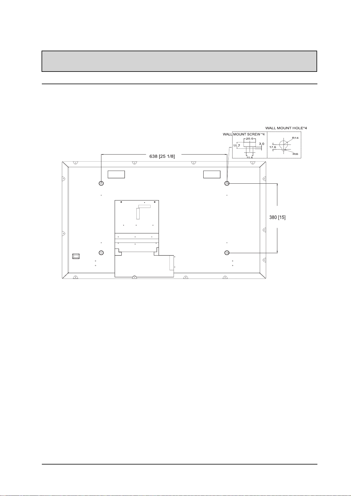
Rear View
WALL MOUNT (OPTION)
Note:
! Follow mount bracket instruction included in mounting kit.
! This type of equipment is to be installed by qualified installers, please contact with authorized dealer
for installation.
35
Page 39

280 William Street, Melbourne VIC 3000
3 9672 2400
8,20-22 Foundry Rd, Seven Hills, NSW 2147
355 Montague Road, West End, QLD 4101
way,
Sir D.Bradman & Marion Roads,
8811 4000
3010 0100
9 6522
TINSE2091
1
 Loading...