

Page 1

Series
Programmable DC Power Supplies
200W/400W/600W/800W
Built-in USB, RS-232 & RS-485 Interface
USER MANUAL
This Manual Covers Models:
Z10-20 Z20-10 Z36-6 Z60-3.5 Z100-2
Z10-40 Z20-20 Z36-12 Z60-7 Z100-4
Z10-60 Z20-30 Z36-18 Z60-10 Z100-6
Z10-72 Z20-40 Z36-24 Z60-14 Z100-8
IA710-04-01K
Page 2
0.1wt%
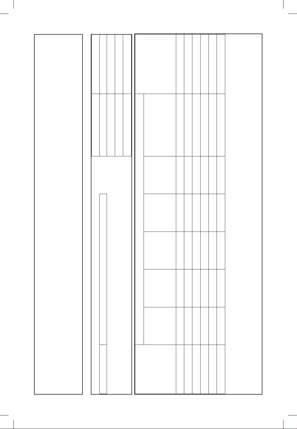
Concentration Values of Toxic and Hazardous Substances/Elements (wt%) Notes
Ethers (PBDE)
Polybrominated Diphenyl
Biphenyls (PBB)
Polybrominated
(Cr6+)
Chromium
Hexavalent
Cadmium (Cd)
Mercury (Hg)
0.1wt%
0.1wt%
0.1wt%
0.1wt%
Product Weight Z200: 1.9Kg
Product Weight Z400: 1.9Kg
Product Weight Z600: 2.1Kg
Product Weight Z800: 2.1Kg
Date of manufacture
Information Concerning Inclusion of Toxic and Hazardous Substances
This information sheet was prepared based on People's Republic of China ”Management Methods for Controlling Pollution Caused by Electronic Information Products Regulation”and
Series: Z200, Z400, Z600, Z800 POWER SUPPLY
+
Z
0.1wt%
Lead (Pb)
Part Name
O : Indicates that the concentration values of toxic and hazardous substances in all ”homogeneous materials” of respective parts and materials does not exceed the concentration limits
regulated by ”SJ/T 11363-2006 Requirements for Concentration Limits for Certain Hazardous Substances in Electronic Information Products”.
X : Indicates that the concentration value of a toxic or hazardous substance included in a ”homogeneous part” of a respective part or material exceeds the concentration limit regulated by
”SJ/T 11364—2006 Marking for Control of Pollution Caused by Electronic Information Products”.
As People's Republic of China ”Management Methods for Controlling Pollution Caused by Electronic Information Products Regulation” is a different legislation from EU RoHS2 Directive
(2011/65/EU), inquiries concerning EU RoHS2 Directive (2011/65/EU) information should be done separately.
Case O O O O O O
Accessories O O O O O O Provided in the package
Inner cables O O O O O O
Inner metal parts O O O O O O
PCB's assembly X O O O O O
Plastic panel O O O O O O
”SJ/T 11363-2006 Requirements for Concentration Limits for Certain Hazardous Substances in Electronic Information Products”.
Page 3

Table of Contents
WARRANTY ............................................................................................................................................. 8
REGULATORY NOTICES ....................................................................................................................... 9
SAFETY INSTRUCTIONS ...................................................................................................................... 9
CHAPTER 1: GENERAL INFORMATION
1.1 User Manual Content .................................................................................................................. 13
1.2 Introduction ................................................................................................................................... 13
1.2.1 General Description ................................................................................................................................. 13
1.2.3 Features and Options ............................................................................................................................. 13
1.2.4 Multiple Output Power System ........................................................................................................ 14
1.2.5 Control via the USB or RS232/485 Communication Ports ................................................ 14
1.2.6 Analog Voltage Programming and Monitoring ..................................................................... 14
1.2.7 Parallel Operation ..................................................................................................................................... 14
1.2.8 Output Connections ............................................................................................................................... 14
1.2.9 Cooling and Mechanical Construction ........................................................................................ 14
1.3 Accessories .....................................................................................................................................15
1.3.1 General ............................................................................................................................................................. 15
1.3.2 Serial Link Cable ......................................................................................................................................... 15
1.3.3 Misc. Hardware ........................................................................................................................................... 15
1.3.4 AC Cables ........................................................................................................................................................ 15
1.3.5 Serial Port Cables ........................................................................................................................................ 15
CHAPTER 2: SPECIFICATIONS
+
200 Series Specifications ....................................................................................................... 16
2.1 Z
2.2 Z+400 Series Specifications ...................................................................................................... 20
2.3 Z+600 Series Specifications ...................................................................................................... 24
2.4 Z+800 Series Specifications ....................................................................................................... 28
2.5 Supplemental Characteristics ..................................................................................................31
2.6 Z200W/400W/600W/800W Outline Drawing ..................................................................... 32
2.7 Z200W/400W/600W/800W Optional IEEE, Isolated Analog
Interface Outline Drawing ....................................................................................................... 33
2.8 Z200W/400W/600W/800W Front Panel Output Binding
Post/Socket Outline Drawing L/L2 ....................................................................................... 34
CHAPTER 3: INSTALLATION
3.1 General ............................................................................................................................................. 35
3.2 Preparation for Use ......................................................................................................................35
3.3 Initial Inspection ........................................................................................................................... 35
3.4 Rack Mounting .............................................................................................................................. 35
3.5 Location, Mounting and Cooling ........................................................................................... 36
3.6 AC Source Requirements ........................................................................................................... 36
3.7 AC Input Power Connection ..................................................................................................... 36
3.7.1 AC Input Connector .................................................................................................................................. 36
3.7.2 AC Input Cord ............................................................................................................................................... 37
3.8 Turn-On Checkout Procedure ..................................................................................................37
3.8.1 General ............................................................................................................................................................. 37
3.8.2 Prior to Operation ...................................................................................................................................... 37
3.8.3 Constant Voltage Check ........................................................................................................................ 38
3.8.4 Constant Current Check ......................................................................................................................... 38
3.8.5 OVP Check ......................................................................................................................................................38
3.8.6 UVL Check ...................................................................................................................................................... 38
3.8.7 Foldback Check ........................................................................................................................................... 39
Page 4

3.9 Connecting the Load .................................................................................................................. 39
3.9.1 Load Wiring .................................................................................................................................................... 39
3.9.2 Current Carrying Capacity .................................................................................................................... 40
3.9.3 Wire Termination ........................................................................................................................................ 41
3.9.4 Noise and Impedance Effects ............................................................................................................. 41
3.9.5 Inductive Loads ........................................................................................................................................... 41
3.9.6 Making the Load Connections........................................................................................................... 41
3.9.7 Connecting Single Loads, Local Sensing (default) ................................................................. 43
3.9.8 Connecting Single Loads, Remote Sensing ............................................................................... 43
3.9.9 Connecting Multiple Loads, Radial Distribution Method .................................................. 44
3.9.10 Multiple Load Connection with Distribution Terminals ...................................................44
3.9.11 Grounding Outputs ................................................................................................................................ 45
3.10 Local and Remote Sensing ...................................................................................................... 45
3.10 .1 Sense W iring ................................................................................................................................................ 45
3.10.2 Local Sensing .............................................................................................................................................. 46
3.10.3 Remote Sensing ........................................................................................................................................ 46
3.10.4 J2 Sense Connector Technical Information ............................................................................. 47
3.11 Repackaging for Shipment ..................................................................................................... 47
CHAPTER 4: FRONT/REAR PANEL CONTROLS AND CONNECTORS
4.1 Introduction ...................................................................................................................................48
4.2 Front Panel Display and Controls .......................................................................................... 48
4.3 Rear Panel Connectors ............................................................................................................... 50
4.3.1 J1 Connector Terminal and Function ............................................................................................. 52
4.3.2 J3 Connector Terminal and Function ............................................................................................ 53
4.4 Front Panel Display Messages .................................................................................................54
4.5 Navigating the Main Menu ...................................................................................................... 55
4.5.1 Introduction ................................................................................................................................................... 55
4.5.2 Exiting the Main Menu ........................................................................................................................... 56
4.6 Navigating Communication Menu ........................................................................................ 56
4.6.1 Introduction ................................................................................................................................................... 56
4.6.2 Exiting the Communication Menu .................................................................................................57
4.7 Navigating the Protection Menu ............................................................................................ 57
4.7.1 Introduction .................................................................................................................................................. 57
4.7.2 Exiting the Protection Menu ............................................................................................................... 57
CHAPTER 5: LOCAL OPERATION
5.1 Introduction ...................................................................................................................................58
5.2 Standard Operation .....................................................................................................................58
5.2.1 Constant Voltage Mode and Voltage Setting ........................................................................... 58
5.2.2 Constant Current Mode and Current Setting ........................................................................... 58
5.2.3 Automatic Crossover ................................................................................................................................ 59
5.2.4 Output On/Off Control ...........................................................................................................................59
5.2.5 Safe Start and Auto-Restart Modes................................................................................................. 59
5.2.6 Viewing Software Revision ................................................................................................................... 59
5.3 Alarms and Protective Functions ...........................................................................................60
5.3.1 Introduction ................................................................................................................................................... 60
5.3.2 Over Voltage Protection ........................................................................................................................ 60
5.3.2.1 Setting the OVP Level .......................................................................................................................... 60
5.3.2.2 Resetting the OVP Circuit .................................................................................................................. 61
5.3.3 Under Voltage Protection and Under Voltage Limit ........................................................... 61
5.3.3.1 Setting the UVP/UVL Mode and Level ....................................................................................... 61
5.3.3.2 Activated UVP Alarm ............................................................................................................................ 61
5.3.4 Foldback Protection ................................................................................................................................ 61
Page 5

5.3.4.1 Setting the Foldback Protection .................................................................................................. 62
5.3.4.2 Activated FOLD Alarm ......................................................................................................................... 62
5.3.5 Protection Delay ......................................................................................................................................... 62
5.3.5.1 Setting the Protection Delay ........................................................................................................... 62
5.3.6 Over Temperature Protection ............................................................................................................. 62
5.3.7 AC Fail Alarm ................................................................................................................................................. 62
5.4 Series Operation ........................................................................................................................... 63
5.4.1 Series Connection for Increased Output Voltage ................................................................... 63
5.4.2 Series Connection for Positive and Negative Output Voltage ....................................... 64
5.4.3 Remote Programming in Series Operation ................................................................................64
5.5 Parallel Operation ........................................................................................................................65
5.5.1 Introduction ................................................................................................................................................... 65
5.5.2 Basic Parallel Operation .......................................................................................................................... 65
5.5.2.1 Master Unit Set Up ................................................................................................................................. 65
5.5.2.2 Slave Unit Set Up .................................................................................................................................... 66
5.5.2.3 Setting Over Voltage Protection ................................................................................................... 66
5.5.2.4 Setting Foldback Protection ............................................................................................................ 66
5.5.2.5 Connection to Load ..............................................................................................................................66
5.5.3 Advanced Parallel Operation .............................................................................................................. 68
5.5.3.1 Master Unit Set Up ................................................................................................................................. 68
5.5.3.2 Slave Unit Set Up .................................................................................................................................... 68
5.6 Daisy-Chain Connection ............................................................................................................ 69
5.7 Rear Panel (J3 Connector) Functions and Settings .......................................................... 69
5.7.1 External Shut Off Function .................................................................................................................... 70
5.7.2 Interlock Function - Analog On/Off. (Enable/Disable) ......................................................... 70
5.7.3 Auxiliary Programmed Function Pin 1 and Pin 2 .................................................................... 71
5.7.4 Power Supply OK Signal ......................................................................................................................... 72
5.8 Rear Panel (J1 Connector) Functions.....................................................................................72
5.8.1 CV/CC Signal .................................................................................................................................................. 72
5.9 Parameter Setting Memory ...................................................................................................... 73
5.9.1 Default Setting ............................................................................................................................................. 73
5.9.2 Reset ................................................................................................................................................................... 73
5.9.3 Last Setting Memory ................................................................................................................................ 73
5.9.4 Save <1..4> ...................................................................................................................................................... 74
5.9.5 Recall <1..4> ................................................................................................................................................... 74
CHAPTER 6: REMOTE ANALOG PROGRAMMING
6.1 Introduction ................................................................................................................................... 76
6.2 Local/Remote Analog Control ................................................................................................. 76
6.3 Local/Remote Analog Indication ............................................................................................ 76
6.4 Remote Voltage Programming of Output Voltage and Current .................................77
6.5 Remote Resistor Programming of Output Voltage and Output Current ................. 78
6.6 Programming Monitoring of Output Voltage (V_MON) and Current (I_MON) .... 79
CHAPTER 7: Serial RS232/RS485 and USB Interface
7.1 Introduction .................................................................................................................................... 80
7.2 Configuration ................................................................................................................................. 80
7.2.1 Default Setting ............................................................................................................................................. 80
7.2.2 Address Setting ........................................................................................................................................... 80
7.2.3 Communication Interface Selection ............................................................................................. 80
7.2.4 Baud Rate Setting ....................................................................................................................................... 81
7.2.5 Language Selection (RS232/RS485, USB) ..................................................................................... 81
7.2.6 Setting Unit in Remote, Local Lockout or Local Mode ........................................................81
7.3 Rear Panel RS232/485 Connector ........................................................................................... 82
Page 6

7.4 Connectig Power Supply To RS232 Or RS485 BUS ............................................................ 83
7.5 Rear Panel USB Connector ........................................................................................................84
7.5.1 USB Getting Started ...................................................................................................................................84
7.6 Multi Power Supply Connection to RS232 Or RS485 or USB ......................................... 84
7.7 GEN Protocol (GEN series communication language) .....................................................85
7.7.1 Da t a F o rm at .................................................................................................................................................... 85
7.7.2 End of Message ............................................................................................................................................ 85
7.7.3 Command Repeat .......................................................................................................................................85
7.7.4 C he ck su m ........................................................................................................................................................ 85
7.7.5 Acknowledge ................................................................................................................................................ 85
7.7. 6 Ba c ksp a ce ........................................................................................................................................................ 85
7.7.7 Error Messages ..............................................................................................................................................85
7.8 GEN Command Set Description .............................................................................................. 86
7.8.1 General guides ............................................................................................................................................. 86
7.8.2 Command Set Categories .....................................................................................................................86
7.8.3 Identification Commands ......................................................................................................................86
7.8.4 Initialization Commands ....................................................................................................................... 87
7.8.5 Output Commands ................................................................................................................................... 87
7.8.6 Global Output Commands ................................................................................................................... 89
7.8.7 Auxiliary Commands ................................................................................................................................ 91
7.8.8 Status Commands ...................................................................................................................................... 91
7.9 Serial Communication Test Set-Up .........................................................................................92
7.10 SCPI Protocol ................................................................................................................................ 92
7.10.1 Dat a Forma t.................................................................................................................................................. 92
7.10.2 End of Message ......................................................................................................................................... 92
7.10.3 End of Command .................................................................................................................................... 92
7.10.4 Checksum ..................................................................................................................................................... 93
7.10.5 SCPI Requirements .................................................................................................................................. 93
7.10.6 SCPI Command Hierarchy ................................................................................................................... 93
7.10.7 Header ............................................................................................................................................................. 93
7.10.8 Data Formats ............................................................................................................................................... 94
7.10.9 Character Data ............................................................................................................................................ 94
7.10.10 Commands Notes .................................................................................................................................. 94
7.11 SCPI Common Commands.......................................................................................................94
7.12 SCPI Subsystem Commands ................................................................................................... 99
7.12.1 Output Subsystem ................................................................................................................................... 99
7.12.2 Instrument Subsystem ......................................................................................................................... 102
7.12.3 Voltage Subsystem ................................................................................................................................. 102
7.12.4 Current Subsystem .................................................................................................................................104
7.12.5 Measure Subsystem ............................................................................................................................... 105
7.12.6 DISPlay Subsystem ..................................................................................................................................106
7.12.7 INITiate Subsystem..................................................................................................................................107
7.12.8 LIST Subsystem ......................................................................................................................................... 107
7.12.9 STATus Subsystem ................................................................................................................................... 109
7.12.10 SYSTem Subsystem .............................................................................................................................. 111
7.12.11 TRIGger Subsystem ............................................................................................................................... 112
7.12.12 WAVE Subsystem ................................................................................................................................... 113
7.12.13 Global Subsystem .................................................................................................................................. 114
7.13 Command Summary................................................................................................................. 115
CHAPTER 8: ADVANCED FUNCTIONS
8.1 Introduction .................................................................................................................................. 119
8.2 FIX Mode ........................................................................................................................................ 119
8.3 LIST Mode ...................................................................................................................................... 120
Page 7

8.4 WAVE Mode ................................................................................................................................... 121
8.5 Trigger .............................................................................................................................................122
8.5.1 Input Trigger ................................................................................................................................................. 122
8.5.2 Output Trigger ............................................................................................................................................123
8.6 Transient Waveform Example ................................................................................................. 123
8.6.1 Wave Programing...................................................................................................................................... 12 3
8.6.2 Wave Execution via Communication PC .................................................................................... 123
8.6.3 Wave Execution via Front Panel ...................................................................................................... 124
8.7 Additional Examples .................................................................................................................. 124
8.7.1 List Example .................................................................................................................................................. 124
8.7.2 Waveform Example .................................................................................................................................. 124
CHAPTER 9: STATUS, FAULT AND SRQ REGISTERS
9.1 General ............................................................................................................................................ 125
9.2 Power Supply Status Structure ............................................................................................... 126
9.3 Condition Registers ....................................................................................................................126
9.3.1 Fault Register ...............................................................................................................................................126
9.3.2 Status Register ............................................................................................................................................. 127
9.4 Conditional, Enable and Event Registers ............................................................................ 127
9.4.1 Conditional Registers. ............................................................................................................................. 127
9.4.2 Event Registers. ...........................................................................................................................................127
9.4.3 Enable Register ........................................................................................................................................... 127
9.5 Service Request .......................................................................................................................... 127
9.6 Standard Event Status Group ..................................................................................................128
9.6.1 Register Functions .................................................................................................................................... 128
9.6.2 Register Commands ................................................................................................................................ 128
9.6.3 Status Byte Register ................................................................................................................................. 129
9.6.4 Determining the Cause of a Service Interrupt .........................................................................129
9.6.5 Output Queue.............................................................................................................................................13 0
9.6.6 Error Messages ............................................................................................................................................130
CHAPTER 10: ISOLATED ANALOG PROGRAMMING OPTION
10.1 Introduction ................................................................................................................................ 132
10.2 Specifications ............................................................................................................................. 132
10.2.1 0-5V/0-10V Option (PN: IS510) ..........................................................................................................132
10.2.2 4-20mA Option (PN: IS420) ............................................................................................................... 132
10.3 Isolated Programming & Monitoring Connector ..........................................................133
10.4 Setup and Operating Instructions ...................................................................................... 134
10.4.1 Setting Up Power Supply for 0-5/0-10V Isolated Programming and Monitoring 134
10.4.2 Setting Up Power Supply for 4-20mA Isolated Programming and Monitoring 134
CHAPTER 11: MAINTENANCE
11.1 Introduction .................................................................................................................................135
11.2 Units Under Warranty .............................................................................................................. 135
11.3 Periodic Maintenance .............................................................................................................. 135
11.4 Adjustments and Calibration ................................................................................................ 135
11.5 Parts Replacement and Repairs ........................................................................................... 135
11.6 Troubleshooting ........................................................................................................................ 135
11.7 Fuse Rating .................................................................................................................................. 136
USER MANUAL INDEX ...................................................................................................................... 139
Page 8

WARRANTY
This TDK-Lambda product is warranted against defects in materials and workmanship for a period
of five years from date of shipment. During the warranty period, TDK-Lambda will, at it’s option,
either repair or replace products which prove to be defective.
Limitation of Warranty
The warranty shall not apply to defects resulting from improper or inadequate usage or maintenance
by the buyer, buyer supplied products or interfacing. The warranty shall not apply to defects resulting
from unauthorized modifications or from operation exceeding the environmental specifications
of the product or if the QA seal has been removed or altered by anyone other than TDK-Lambda
authorised personnel. TDK-Lambda does not warrant the buyers circuitry or malfunctions of
TDK-Lambda products resulting from the buyer’s circuitry. Furthermore, TDK-Lambda does not
warrant any damage occurring as a result of the buyer’s circuitry or the buyer’s supplied products.
No other warranty is expressed or implied.
Warranty Service
This product must be returned to an authorized TDK-Lambda service facility for repairs or other
warranty service. For products returned to TDK-Lambda for warranty service, the buyer shall prepay
shipping charges to TDK-Lambda and TDK-Lambda shall pay the shipping charges to return the
product to the buyer. Refer to section 3.11 for Repackaging for Shipment.
Disclaimer
The information contained in this document is subject to change without notice. TDK-Lambda
shall not be liable for errors contained in this document or for incidental or consequential damages
in connection with the furnishing, performance or use of this material. No part of this document
may be photocopied, reproduced or translated into another language without the prior written
consent of TDK-Lambda.
Trademark Information
Microsoft™ and Windows™ are trademarks of Microsoft Corporation.
8
Page 9

REGULATORY NOTICES
FCC Notice
This device complies with Part 15 of the FCC Rules. Operation is subject to the following two
conditions: (1) this device may not cause harmful interference, and (2) this device must accept
any interference received, including interference that may cause undesired operation.
NOTE:
This equipment has been tested and found to comply with the limits for a Class A digital device,
pursuant to Part 15 of the FCC rules. These limits are designed to provide reasonable protection
against harmful interference when the equipment is operated in a commercial environment. This
equipment generates, uses, and can radiate radio frequency energy and, if not installed and used in
accordance with the instruction manual, may cause harmful interference to radio communications.
Operation of this equipment in a residential area is likely to cause harmful interference in which case
the user will be required to correct the interference at his own expense.
WARNING:
Modifications not expressly approved by the party responsible for compliance could void the user’s
authority to operate the equipment under FCC Rules.
Safety Approvals
UL 61010-1 and CSA22.2 No.61010-1 - UL Recognized, C-UL for Canada.
IEC 61010-1 - CB Report and Certificate.
EN 61010-1 - CE mark.
EN 61326-1
Marking by the CE Symbol indicates compliance to the LVD and EMC Directives of the European Union.
A “Declaration of Conformity” in accordance with the preceding directives and standards has been
made and is on file at our EU representative TDK LAMBDA UK, located at Kingsley Avenue,
Ilfracombe, Devon EX34 8ES, UK.
A “Declaration of Conformity” may be accessed via company web site:
www.uk.tdk-lambda.com/technical-data/
WARNING:
This is a Class A product. On a domestic environment, this product may cause radio interference in
which case user may be required to take adequate measures.
OTHER
Z200, Z400, Z600, Z800 series are comply with the following Directives:
• RoHS2 Directive (2011/65/EU);
• WEEE Directive (2002/96/EC).
SAFETY INSTRUCTIONS
CAUTION:
The following safety precaution must be observed during all phases of operation, service and repair
of this equipment. Failure to comply with the safety precautions or warnings in this document violates
safety standards of design, manufacture and intended use of this equipment and may impair the built-in
protections within. TDK-Lambda shall not be liable for user’s failure to comply with these requirements.
VORSICHT:
Die folgenden Sicherheitsvorschriften müssen vor Inbetriebnahme und in jedem Betriebszustand bei
Service oder Reparatur beachtet werden. Missachtung der Sicherheitsvorschriften und Warnhinweise
aus diesem Handbuch führen zur Verletzung der bestehenden Sicherheitsstandards. Bei Betrieb
des Gerätes außerhalb des bestimmungsgemäßen Einsatzes können die im Gerät integrierten
Schutzfunktionen beeinträchtigt werden. TDK-Lambda ist nicht haftbar für Schäden, die durch
Missachtung dieser Sicherheitsvorschriften entstehen können.
9
Page 10

+
Z
series units are not authorized for use as critical component in nuclear control systems, life support
systems or equipment for use in hazardous environments without the express written approval of
the managing director of TDK-Lambda.
VORSICHT:
CAUTION:
Die Geräte der
Z+ Serie sind ohne ausdrückliche schriftliche Genehmigung des Geschäftsführers von
TDK-Lambda nicht für die Benutzung als kritische Komponente in nuklearen Steuerungssystemen,
lebenserhaltenden Systemen oder Geräten für den Einsatz in gefährlichen Umgebungen zugelassen.
OVERVOLTAGE CATEGORY AND ENVIRONMENTAL CONDITIONS
+
series units have been evaluated to Overvoltage category II.
The Z
The Z+ series units are intended for use in the following operation conditions:
* Indoor use
* Pollution degree 2
* Max. operational altitude: 3000m above sea level
* Ambient temperature: 0°C-50°C.
ÜBERSPANNUNGSKATEGORIE UND UMWELTBEDINGUNGEN
+
Die Geräte der Z
Serie wurden hinsichtlich der Uberspannungskategorie II klassifiziert.
Die Geräte der Z+ Serie sind zur Benutzung unter folgenden Betriebsbedingungen vorgesehen:
* Benutzung in Innenräumen
* Verschmutzungsgrad 2
* Maximale geografische Höhe für den Betrieb: 3000 m über Null
* Umgebungstemperatur: 0 °C – 50 °C.
GROUNDING
+
series units are Class I product. To minimize electrical shock hazard, the Z+ series units must be
Z
connected to an electrical ground. The instruments must be connected to the AC power supply
mains through a standard certified three-wire power cable, with the ground wire firmly connected
to an electrical ground (safety ground) at the power outlet. Any interruption of the protective
ground conductor or disconnection of the protective earth terminal will cause a potential shock
hazard that might cause personal injury.
ERDUNG
+
Gerate der Z
Serie sind Produkte der Schutzkklasse I. Zur Minimierung der Stromschlaggefahr
müssen die Gerate der Z+ Serie elektrisch geerdet werden. Die Geräte müssen über ein genormtes,
dreiadriges Netzkabel angeschlossen werden. Die Erdungsleitung des Netzkabels muss mit dem
Erdungskontakt der Steckdose sicher verbunden sein. Eine Unterbrechung der Erdungsverbindung
der Stromversorgung kann die potentielle Gefahr eines elektrischen Schlags zur Folge haben.
LIVE CIRCUITS
+
Operating personnel must not remove the Z
series unit cover.
No internal adjustment or component replacement is allowed by non-TDK-Lambda qualified
service personnel. Never replace components with power cable connected. To avoid injuries,
always disconnect power, discharge circuits and remove external voltage sources before touching
components.
SPANNUNGSFÜHRENDE Teile
+
Das Gehäuse der Z
Geräte darf von Anwendern nicht geöffnet werden.
Modifikationen sowie der Austausch von Bauteilen ist ausschließlich qualifizierten
Mitarbeitern der TDK-Lambda erlaubt.
Um Verletzungen zu vermeiden, sind vor Arbeiten im Gerät alle Anschlüsse zu trennen, Kapazitäten
zu entladen und Fremdspannungsquellen zu entfernen.
10
Page 11

PARTS SUBSTITUTIONS & MODIFICATIONS
Parts substitutions and modifications are by authorized TDK-Lambda service personnel only. For
repairs or modifications, the instrument must be returned to TDK-Lambda service facility.
AUSWECHSELN UND VERÄNDERUNG VON BAUTEILEN
Das Auswechseln sowie die Veränderung von Teilen darf nur von autorisierten TDK-Lambda
Servicemitarbeitern durchgefuhrt werden. Fur Reparaturen oder Veränderungen muss das Gerat
an den TDK-Lambda Kundendienst zurückgeschickt werden.
AC INPUT
+
Do not connect Z
series unit to mains supply exceeding the input voltage and frequency rating.
The input voltage and frequency rating is: 100-240V~, 50/60Hz. For safety reasons, the mains
supply voltage fluctuations should not exceed +/-10% of nominal voltage.
Netzeingang
+
Gerate der Z
Serie nicht an einen Netzanschluss anschliesen, dessen Eingangsspannung und
Frequenz über die Gerätespezifikation hinausgehen. Eingangsspannung und Frequenz betragen:
100-240 V~ 50/60 Hz. Für sicheren Betrieb des Gerätes ist eine Abweichung von maximal +/-10 %
von der Nominalspannung erlaubt.
ENERGY HAZARD
+
The main output of Z
series units is capable of providing hazardous energy. Due to hazardous
energy level the output and connections therefore must not be user accessible. Manufacturer's
final equipment must provide protection to service personnel against inadvertent contact with
output bus bars.
GEFÄHRLICHE ENERGIEINHALTE
Der Ausgang der Z+ Geräte könnte gefährliche Energieinhalte bereitstellen. Aufgrund des
gefährlichen Energiepotentials dürfen der Ausgang und Verbindungsleitungen für Endanwender
nicht berührbar sein. Der Einbau in ein Endgerät muss so erfolgen, dass das Bedienpersonal nicht
versehentlich mit den Ausgangsanschlüssen in Kontakt kommen kann.
FUSE
Internal fuse is sized for fault protection and if a fuse was opened it would indicate that service is
required. Fuse replacement should be made by qualified technical personnel.
Refer to maintenance instructions in Chapter 11 for fuse ratings.
SICHERUNG
Die interne Sicherung trennt das Gerät im Fehlerfall von der Netzspannung. Hat die Sicherung
ausgelöst, ist das Gerät defekt. Die Sicherung darf nur durch qualifizierte
technische Fachkräfte ausgetauscht werden.
Die Sicherungswerte entnehmen Sie der Wartungsanleitung in Kapitel 11.
WARNING:
There is electric shock hazard when the power supply output is adjusted above 60VDC
Ensure that there is no possibility to touch simultaneously one of the output pins and earth (including
the power supply’s metal enclosure) nor to touch simultaneously one of the output pins and metal
parts of any external products supplied by the power supply when the output is adjusted above 60VDC.
WARNUNG:
Bei einer eingestellten Ausgangsspannung von über 60VDC besteht die potentielle Gefahr eines
elektrischen Schlages. Stellen Sie sicher, dass niemals ein Ausgangspol und Erde (einschließlich das
Metall-Gehäuse der Stromversorgung) gleichzeitig berührt werden können. Dies gilt in gleicher
Weise für einen Ausgangspol und andere leitfähige Komponenten der angeschlossenen Last, wenn
die Ausgangsspannung der Stromversorgung auf einen Wert von über 60VDC eingestellt ist.
11
Page 12
WARNING:
There is a potential shock hazard when using a power supply with an output voltage greater than
60VDC. Do not turn ON power supply when output voltage is above 60VDC without output bus-bars
and output connectors protection assembled. Turn OFF power supply or disconnect power supply
from AC mains before making or changing any rear panel connection.
WARNUNG:
Bei Einsatz einer Stromversorgung von über 60VDC Nennspannung besteht eine potentielle
Gesundheitsgefahr durch elektrischen Schlag. Schalten Sie keine Stromversorgung mit einer
Ausgangsspannung von über 60VDC EIN, ohne dass die Schutzabdeckungen der Ausgangsstecker und
Ausgangs-Stromschienen montiert sind. Schalten Sie die Stromversorgung AUS oder ziehen Sie den
Netzstecker, bevor Sie Anschlüsse auf der Rückseite vornehmen oder verändern.
GERÄUSCHPEGEL
Maschinenlärminformations - Verordnung - 3. GPSGV, der höchste Schalldruckpegel beträgt
weniger als 70 dB(A) gemäss EN ISO7779.
SYMBOLS
Caution, risk of danger. Instruction manual symbol. The instrument will be marked
with this symbol when it is necessary for the user to refer to the instruction manual.
Achtung Gefahr. Symbol im Benutzerhandbuch. Das Gerät wird mit diesem Symbol
gekennzeichnet, wenn der Benutzer Anweisungen im Handbuch beachten muss.
Indicates ground terminal.
Zeigt einen Erdungsanschluss an.
Protective Conductor Terminal.
Schutzleiterklemme.
ON (Supply).
EIN (Zufuhr).
OFF (Supply).
AUS (Zufuhr).
Standby (Supply) .
Standby (Zufuhr) .
Direct current (DC).
Gleichstrom (DC).
Alternate current (AC).
Wechselstrom (AC).
Denotes hazard. An attention to a procedure is called. Not following the procedure
correctly could result in personal injury. A WARNING sign should not be skipped and
all indicated conditions must be fully understood and met.
Bezeichnet Gefahren. Es wird die Beachtung eines Verfahrens empfohlen. Nichteinhaltung
des Verfahrens kann zu Körperverletzung führen. Ein WARN-H inweis darf nicht ignoriert
und alle angeführten Verfahren müssen eindeutig verstanden und umgesetzt werden.
Denotes hazard. An attention to a procedure is called. Not following the procedure
correctly could result in damage to the equipment.
Bezeichnet Gefahren. Es wird die Beachtung eines Verfahrens empfohlen. Mangelhafte
Einhaltung des Verfahrens kann zu Beschädigung der Geräte führen.
12
Page 13

CHAPTER 1: GENERAL INFORMATION
1.1 User Manual Content
This user's manual contains the operating instructions, installation instructions and specifications
of the Z+ Series 200W, 400W, 600W and 800W power supply series. The instructions refer to the
standard power supplies, including the built-in USB and RS232/485 serial communication. For
information related to operation with the optional LAN and IEEE, refer to User Manual for power
supply LAN and IEEE.
1.2 Introduction
1.2.1 General Description
+
Series power supplies are wide output range, high performance switching power supplies. The
Z
Z+ Series is power factor corrected and operates from worldwide AC voltage range continuously.
Output voltage and current are continuously displayed and LED indicators show the complete
operating status of the power supply. The Front Panel controls allow the user to set the output
parameters, the protection levels (Over-Voltage protection, Under-Voltage protection and Foldback)
and preview the settings. The rear panel includes the necessary connectors to control and monitor
the power supply operation by remote analog signals or by the built-in serial communication USB
and RS232/485. LAN, IEEE and Isolated-Analog programming/monitoring are optional.
1.2.2 Models Covered by this Manual
Model Voltage range (V) Current range (A) Model Voltage range (V) Current range (A)
Z10-20 0-10 0-20 Z60-3.5 0-60 0-3.5
Z10-40 0-10 0-40 Z60-7 0-60 0-7
Z10-60 0-10 0-60 Z60-10 0-60 0-10
Z10-72 0-10 0-72 Z60-14 0-60 0-14
Z20-10 0-20 0-10 Z100-2 0-100 0-2
Z20-20 0-20 0-20 Z100-4 0-100 0-4
Z20-30 0-20 0-30 Z100-6 0-100 0-6
Z20-40 0-20 0-40 Z100-8 0-100 0-8
Z36-6 0-36 0-6
Z36-12 0-36 0-12
Z36-18 0-36 0-18
Z36-24 0-36 0-24
1.2.3 Features and Options
• Constant Voltage / Constant Current with automatic crossover.
• Active Power Factor correction.
• Universal Input Voltage 85-265Vac, continuous operation.
• Embedded Microprocessor Controller.
• Built in USB & RS232/485 Interface.
• Voltage & Current high resolution adjustment by digital Encoders.
• High resolution 16 bit ADCs & DACs.
• Software Calibration (no internal trimmers / potentiometers).
• Last Setting Memory.
• Independent Remote ON/OFF (Opto-Isolated) and Remote Enable/Disable.
• Parallel operation (Master/Slave) with Active current sharing.
• Remote sensing to compensate for voltage drop of power leads.
• External Analog Programming and Monitoring (0-5V or 0-10V, user selectable).
• Cooling fan speed control for low noise and extended fan life.
• Optional LAN interface (SCPI compatible).
• Optional IEEE interface (SCPI compatible).
• Optional Isolated Analog programming/monitoring (0-5V or 0-10V, user selectable and 4-20mA).
13
Page 14

1.2.4 Multiple Output Power System
+
Series power supplies series can be configured into a programmable power system of up
The Z
to 31 units using the built-in USB or RS232/RS485 communication port in the power supply and
the RS485 linking cable provided with each power supply.
In a LAN system, each power supply can be controlled using the optional LAN controller (factory
installed). In an IEEE system, each power supply can be controlled using the optional IEEE controller
(factory installed).
1.2.5 Control via the USB or RS232/485 Communication Ports
The following parameters can be programmed via the serial communication port:
• Output voltage setting.
• Output current setting.
• Output voltage measurement.
• Output current measurement.
• Output on/off control.
• Foldback protection setting.
• Over-voltage protection setting and readback.
• Under-Voltage protection setting and readback.
• Under-Voltage limit setting and read back.
• Power-supply start up mode (last setting or safe mode).
1.2.6 Analog Voltage Programming and Monitoring
Analog inputs and outputs are provided at the rear panel for analog control of the power supply.
The output voltage and the current limit can be programmed by analog voltage or by resistor,
and can be monitored by analog voltage. The power supply output can be remotely set to On
or Off and analog signals monitor the proper operation of the power supply and the mode of
operation (CV/CC).
1.2.7 Parallel Operation
+
Up to six Z
Series power supplies of the same output voltage and current rating can be paralleled
in master-slave configuration with automatic current sharing to increase available power.
1.2.8 Output Connections
Output connections are made to rear panel bus-bars. Either the positive or negative terminal
may be grounded or the output may be floated. The power supplies shall not float outputs more
than +/- 100VDC above / below chassis ground. Contact factory for assistance with higher float
voltage applications.
Local or remote sense may be used. In remote sense, the voltage drop on the load wires should
be minimized. Refer to the specifications for the maximum voltage drop value.
1.2.9 Cooling and Mechanical Construction
+
Series is cooled by an internal fan. At installation, care must be taken to allow free air flow
The Z
into the power supply via the front panel, and out of the power supply via the rear panel. The Z+
Series power supply is a compact and lightweight unit which allows for easy installation and gives
a space saving solution for customer applications.
14
Page 15

Observe all torque guidelines within this manual. Over torque may damage unit or accessories.
Such damage is not covered under manufacturers warranty.
CAUTION:
1.3 Accessories
1.3.1 General
Accessories are delivered with the power supply or separately upon ordering, The list below shows
the possible accessories and ordering numbers.
1.3.2 Serial Link Cable
Serial link cable, for linking power supplies by RS485 communication is provided with the power
supply.
Cable description: 0.5m length, shielded, RJ-45 type plugs, 8 contacts (P/N: GEN/RJ45).
1.3.3 Misc. Hardware
• Bus bars protection
• Connector protection
• Connector housing IPD1-06-D-K(SAMTEC)
• Connector housing IPD1-04-D-K(SAMTEC)
• Connector housing IPD1-02-D-K(SAMTEC)
• Contact pins P/N: CC79R-2024-01-L(SAMTEC)
1.3.4 AC Cables
AC cables are not provided with the power supply. If an AC cable is required, it should be ordered
according to the following:
Part no. Market Description
Z-U USA 13A 125V, non shielded, 2m typical length, with IEC60320-1, type C15
connector on one end and NEMA-5-15P type plug on the other end.
Z-E Europe 10A 250V, non shielded, 2m typical length, with IEC60320-1, type C15
connector on one end and IEC60884-1 type plug on the other end.
Z-J Japan 15A 125V, non shielded, 2m typical length, with IEC60320-1, type C15
connector on one end and Japan JIS C8303 type plug on the other end.
Z-C China 10A 250V, non shielded, 2m typical length, with IEC60320-1, type C15
connector on one end and China GB2099 or GB1002 type plug on the
other end.
Z-O GENERAL 10A 250V, non shielded, 2m typical length, with IEC60320-1, type C15
connector on one end and non-terminated stripped wires on the other
end. Use the cable only with plug approved by the national safety
standards of the country of usage.
Cable identification: LIVE: Brown ; NEUTRAL: Blue ; EARTH: Green/Yellow.
1.3.5 Serial Port Cables
If a serial port cable is required, it should be ordered according to the description in section 7.2
* USB cables are not provided with the power supply.
15
Page 16
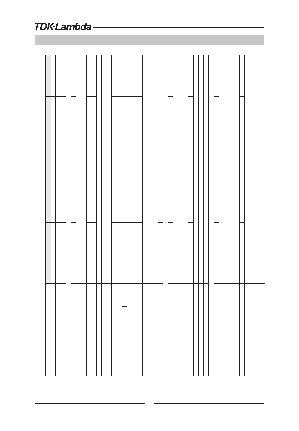
200 Series Specifications
CHAPTER 2: SPECIFICATIONS
12 25 30 40 50
Time for output voltage to recover within 0.5% of its rated output for a load change 10~90% of rated output current.
Output set-point: 10~100%, Local sense
mS
Full load (*9)
No load (*10) (*15)(*17) 40 65 85 100 250
Time delay (*17) 210 250 320 380 1200
Less than 1mS, for models up to and including 100V
No load (*10) (*16)(*17) 200 200 290 310 1100
Output shut-down when power supply change mode from CV to CC or CC to CV. User presetable.
Reset by AC input recycle in autostart mode or by OUTPUT button or by rear panel ENABLE, or by communication port.
Inverter Shut down method. Reset by AC input recycle in autostart mode or by OUTPUT button or by rear panel ENABLE, or by
communication port.
Output shut-down when power supply output voltage goes below UVP programming. User presetable.
Reset by AC input recycle in autostart mode or by OUTPUT button or by rear panel ENABLE, or by communication port.
+
2.1 Z
MODEL Z 10-20 20-10 36-6 60-3.5 100-2
1. Rated output voltage(*1) V 10 20 36 60 100
CONSTANT VOLTAGE MODE Z 10-20 20-10 36-6 60-3.5 100-2
3. Rated output power W 200 200 216 210 200
1. Max. Line regulation (*6) --- 0.01% of rated output voltage+2mV
2. Rated output current (*2) A 20 10 6 3.5 2
5. Temperature coefficient PPM/°C 30PPM/°C from rated output voltage, following 30 minutes warm-up.
2. Max. Load regulation (*7) --- 0.01% of rated output voltage+2mV
3. Ripple and noise (p-p, 20MHz) (*8) mV 50 50 50 50 80
4. Ripple r.m.s. 5Hz~1MHz mV 5 6 6 7 8
9. Up-prog. Response time, 0~Vomax.(*9) mS 15 30 30 50 50
6. Temperature stability --- 0.02% of rated Vout over 8hrs. interval following 30 minutes warm-up. Constant line, load & temp.
7. Warm-up drift --- Less than 0.05% of rated output voltage+2mV over 30 minutes following power on.
8. Remote sense compensation/wire V 1 1 2 3 5
10. Down-prog. response time:
11. Transient response time mS
12. Hold-up time (*19) --- 15mSec Typical. 16mSec Typical.
CONSTANT CURRENT MODE Z 10-20 20-10 36-6 60-3.5 100-2
1. Max. Line regulation (*6) --- 0.01% of rated output current+2mA
2. Max. Load regulation (*11) --- 0.01% of rated output current+5mA
3. Load regulation thermal drift --- Less than 0.05% of rated output current over 30 minutes following load change.
4. Ripple r.m.s. 5Hz~1MHz (*12) mA 25 15 8 4 3
5. Temperature coefficient PPM/°C 100PPM/°C from rated output current, following 30 minutes warm-up.
6. Temperature stability --- 0.05% of rated Iout over 8hrs. interval following 30 minutes warm-up. Constant line, load & temperature.
7. Warm-up drift --- Less than +/-0.1% of rated output current over 30 minutes following power on.
PROTECTIVE FUNCTIONS Z 10-20 20-10 36-6 60-3.5 100-2
1. Foldback protection ---
2. Over-voltage protection (OVP) ---
3. Over -voltage trip point V 0.5~12 1~24 2~40 5~66 5~110
4. Output under voltage limit (UVL) --- Preset by front panel or communication port. Prevents from adjusting Vout below limit. Does not affect in analog programming.
5. Output under voltage protection (UVP) ---
6. Over temperature protection --- User selectable, latched or non latched.
16
Page 17
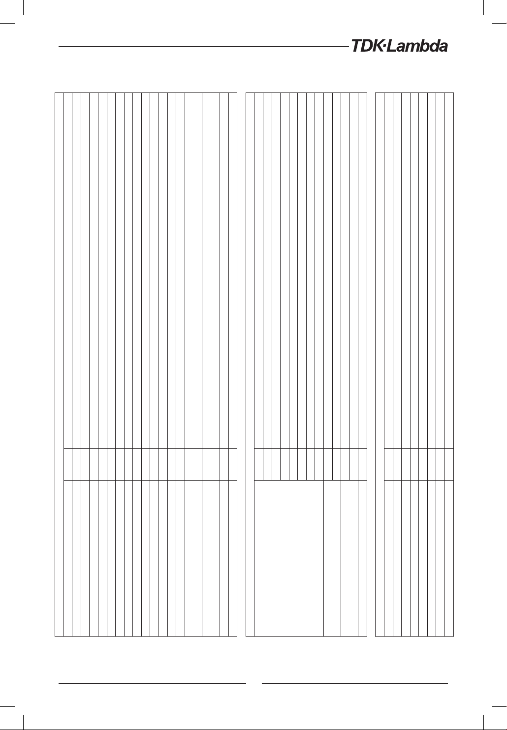
ANALOG PROGRAMMING AND MONITORING
1. Vout voltage programming --- 0~100%, 0~5V or 0~10V, user selectable. Accuracy and linearity: +/-0.5% of rated Vout.
Enables/Disables the PS output by dry contact (Short: On, Open: Off, Source current: less than 0.5mA). Ena/Dis is activated by front panel.
Maximum low level output =0.8V, Minimum high level output =3.8V, Maximum high level output =5V,
Maximum source current =16mA, pulse =20μs Typical.
Maximum low level input =1.2V, Minimum high level input =3.5V, Maximum high level input =5V, Maximum sink current =16mA,
positive edge, trigger: tw =10μs minimum, Tr/Tf =1μs maximum.
--- Multiple options with 2 Encoders
--- Vout/Iout manual adjust
--- OVP/UVL/UVP manual adjust
--- Protection Functions - OVP, UVL,UVP, Foldback, OCP, INT, SO
--- Communication Functions - Selection of LAN,IEEE,RS232,RS485,USB
--- Communication Functions - Selection of Baud Rate, Address
--- Analog Control Functions - Selection Voltage/resistive programming, 5V/10V, 5K/10K programming
--- Analog Control Functions - Selection of Voltage/Current Monitoring 5V/10V, Output ON/OFF, Front Panel Lock.
--- Vout: 4 digits, accuracy: 0.5% of rated output voltage+/-1 count.
--- Iout: 4 digits, accuracy: 0.5% of rated output current+/-1 count.
--- GREEN LEDs: FINE, MENU, PREV, PROT, REM, OUTPUT, CV, CC
--- RED LED: PROT (OVP, UVP, OTP, FOLD, AC FAIL).
--- FINE, MENU, PREV, PROT, REM, OUTPUT
2. Iout voltage programming (*13) --- 0~100%, 0~5V or 0~10V, user selectable. Accuracy and linearity: +/-1% of rated Iout.
3. Vout resistor programming --- 0~100%, 0~5/10Kohm full scale, user selectable. Accuracy and linearity: +/-1% of rated Vout.
4. Iout resistor programming (*13) --- 0~100%, 0~5/10Kohm full scale, user selectable. Accuracy and linearity: +/-1.5% of rated Iout.
5. Shut Off (SO) control --- By electrical Voltage: 0~0.6V/4~15V or dry contact, user selectable logic.
6. Output current monitor (*13) --- 0~5V or 0~10V, user selectable. Accuracy: +/-1%.
7. Output voltage monitor --- 0~5V or 0~10V, user selectable. Accuracy: +/-1%.
8. Power supply OK signal --- 4~5V-OK, 0V-Fail. 500ohm series resistance.
9. Parallel operation (*20) --- Possible, up to 6 units in master/slave mode with single wire current balance connection.
10. Series operation --- 2 identical units (with external diodes).
11. CV/CC indicator --- Open collector. CC mode: On, CV mode: Off. Maximum voltage: 30V, maximum sink current: 10mA
12. Interlock (ILC) control ---
13. Local/Remote mode Control --- By electrical signal or Open/Short: 0~0.6V or short: Remote, 2~15V or open: Local
14. Local/Remote mode Indicator --- Open collector (shunted by 36V zener). On (0~0.6V, 10mA sink current max.)-Remote. Off-Local (30V max.).
15.Trigger out ---
16.Trigger in ---
17. Programmed signal 1 --- Open collector, maximum voltage 25V,maximum sink current 100mA. (Shunted by 27V zener)
18. Programmed signal 2 --- Open collector, maximum voltage 25V,maximum sink current 100mA. (Shunted by 27V zener)
FRONT PANEL
1. Control functions
2. Display
3. Indications
4. Function buttons
PROGRAMMING AND READBACK (RS232/485,USB, Optional: IEEE, LAN)
1. Vout programming accuracy --- 0.05% of rated output voltage
2. Iout programming accuracy (*13) --- 0.1% of actual +0.1% of rated output current
3. Vout programming resolution --- 0.012% of full scale
4. Iout programming resolution --- 0.012% of full scale
5. Vout readback accuracy --- 0.05% of rated output voltage
6. Iout readback accuracy (*13) --- 0.1% of actual +0.3% of rated output current
7. Vout readback resolution --- 0.012% of full scale
8. Iout readback resolution --- 0.012% of full scale
17
Page 18
200 Series Specifications
+
Z
Z 10-20 20-10 36-6 60-3.5 100-2
INPUT CHARACTERISTICS
1. Input voltage/freq. (*3) --- 85~265Vac continuous, 47~63Hz, single phase
2. Maximum Input current 100/200VAC (*4) (*18) --- 2.65/1.31 2.62/1.29 2.76/1.37 2.69/1.33 2.55/1.26
5. Inrush current 100/200VAC (*5) --- Less than 15A/30A
3. Power Factor (Typ) --- >0.99 at 100Vac, >0.98 at 200Vac,100% load
4. Efficiency (Typ) 100/200VAC (*4) (*18) % 76/77.5 77/79 79/80.5 79/80.5 79/81
ENVIRONMENTAL CONDITIONS
1. Operating temperature --- 0~50°C, 100% load.
2. Storage temperature --- -20~85°C
3. Operating humidity % 20~90% RH (no condensation).
4. Storage humidity % 10~95% RH (no condensation).
Maximum 3000m. Derate ambient temp above 2000m.
Operating: Maximum ambient temperature, From 2000m up to 3000m Ambient temperature 40°C.
5. Altitude ---
UL61010-1, EN61010-1, IEC61010-1. Design to meet UL60950-1, EN60950-1
10V≤Vout≤60V: Output,J1,J2,J3,J4,USB,LAN,IEEE/ISOLATED Analog are Non Hazardous
Vout=100V:Output,J1,J2 are Hazardous J3,J4,USB, IEEE/ISOLATED Analog ,LAN are Non Hazardous
10≤Vout≤36V models: Input-Output&J1,J2,J3,J4,USB,LAN/IEEE/ISOLATED ANALOG: 4242VDC/1min; Input-Ground: 2828VDC/1min.
Output&J1,J2,J3,J4,USB,LAN/IEEE/ISOLATED ANALOG-Ground: 707VDC/1min.
60V,100V models: Input-Output&J1,J2: 4242VDC/1min; Input-J3,J4,USB,LAN/IEEE/ISOLATED Analog: 4242VDC/1min; Input-Ground:
2828VDC/1min.
Safety ---
EMC --- IEC/EN61326-1 (Built to meet EN55022/EN55024)
SAFETY/EMC
1. Applicable standards:
2. Withstand voltage ---
18
Output&J1,J2- J3,J4,USB,LAN/IEEE/ISOLATED ANALOG :1910VDC/1min; Output&J1,J2-Ground: 1380VDC/1min.
J3, J4, USB/LAN/IEEE/ISOLATED ANALOG - Ground: 707VDC/1min;
3. Insulation resistance --- More than 100Mohm at 25°C, 70%RH.
4. Conducted emission --- IEC/EN61326-1 Industrial Location - B, FCC part 15-B, VCCI-B
5. Radiated emission --- IEC/EN61326-1 Industrial Location - A, FCC part 15-A, VCCI-A
MECHANICAL
Less than 1.9Kg.
STANDARD Kg
1. Cooling --- Forced air cooling by internal fan.
Less than 2.4Kg. Wide body with Isolated analog or Binding post or IEEE.
H: 83, W: 70, D: 350 (excluding bus bars, handles…). (Refer to Outline drawing).
H: 83, W: 105, D: 350 (excluding bus bars, handles…). (Refer to Outline drawing).
WIDE BODY Kg
STANDARD mm
WIDE BODY mm
2. Weight
3. Dimensions (WxHxD)
4. Vibration --- According to: IEC60068-2-64
5. Shock --- Less than 20G, half sine, 11mS. Unit is unpacked. According to: IEC60068-2-27
Page 19

NOTES:
*1: Minimum voltage is guaranteed to maximum 0.1% of rated output voltage.
*2: Minimum current is guaranteed to maximum 0.2% of rated output current.
*3: For cases where conformance to various safety standards (UL, IEC, etc…) is required, to be described as 100-240Vac (50/60Hz).
*4: Ta=25°C with rated output power.
*5: Not including EMI filter inrush current, less than 0.2mSec at cold start Ta=25°C
*6: At 85~132Vac or 170~265VAC, constant load.
*7: From No-Load to Full-Load, constant input voltage. Measured at the sensing point in Remote Sense.
*8: Measured with JEITA RC-9131A (1:1) probe.
*9: From 10% to 90% or 90% to 10% of Rated Output Voltage, with rated resistive load.
*10: From 90% to 10% of Rated Output Voltage.
*11: For load voltage change, equal to the unit voltage rating, constant input voltage.
*12: For 10V model the ripple is measured at 2V to rated output voltage and rated output current. For other models, the ripple is measured at 10~100%
of rated output voltage and rated output current.
*13: The Constant Current programming, readback and monitoring accuracy do not include the warm-up and Load regulation thermal drift.
*14: Measured with JEITA RC-9131A (1:1) probe.
*15: For cases where the time interval between each down programming is longer than Td (time delay).
*16: For cases where the time interval between each down programming is shorter than Td (time delay).
*17: Td typical Minimum time between consecutive down programming cycles.
*18: PS with Lan, IEEE, models decrease efficiency by 0.5% and increase input current by 0.5%.
PS with Isolated analog option decreases efficiency by 1.5% and increases input current by 1.5%.
*19: At rated output power.
*20: For Parallel operation more than 2 units 5% of total output current is requierd.
19
Page 20
400 Series Specifications
ANALOG PROGRAMMING AND MONITORING
10 10 15 30 50
Time for output voltage to recover within 0.5% of its rated output for a load change 10~90% of rated output current.
Output set-point: 10~100%, Local sense.
mS
Time delay (*17) 210 250 320 380 1200
No load (*10) (*15) (*17) 40 65 85 100 250
Less than 1mS, for models up to and including 100V
No load (*10) (*16) (*17) 200 200 290 310 1100
Output shut-down when power supply change mode from CV to CC or CC to CV. User presetable.
Reset by AC input recycle in autostart mode or by OUTPUT button or by rear panel ENABLE, or by communication port.
Inverter Shut down method. Reset by AC input recycle in autostart mode or by OUTPUT button or by rear panel ENABLE,
or by communication port.
Output shut-down when power supply output voltage goes below UVP programming. User presetable.
Reset by AC input recycle in autostart mode or by OUTPUT button or by rear panel ENABLE, or by communication port.
+
11. Transient response time mS
12. Hold-up time (*19) --- 15mSec Typical. 16mS ec Typical.
CONSTANT CURRENT MODE Z 10-40 20-20 36-12 60-7 100-4
1. Max. Line regulation (*6) --- 0.01% of rated output current+2mA
2. Max. Load regulation (*11) --- 0.01% of rated output current+5mA
3. Load regulation thermal drift --- Less than 0.05% of rated output current over 30 minutes following load change.
4. Ripple r.m.s. 5Hz~1MHz (*12) mA 70 40 15 8 3
5. Temperature coefficient PPM/°C 100PPM/°C from rated output current, following 30 minutes warm-up.
6. Temperature stability --- 0.05% of rated Iout over 8hrs. interval following 30 minutes warm-up. Constant line, load & temperature.
7. Warm-up drift --- Less than +/-0.1% of rated output current over 30 minutes following power on.
PROTECTIVE FUNCTIONS Z 10-40 20-20 36-12 60-7 100-4
1. Foldback protection ---
2.2 Z
MODEL Z 10-40 20-20 36-12 60-7 100-4
1. Rated output voltage(*1) V 10 20 36 60 100
10. Down-prog. response time: Full load (*9)
CONSTANT VOLTAGE MODE Z 10-40 20-20 36-12 60-7 100-4
3. Rated output power W 400 400 432 420 400
1. Max. Line regulation (*6) --- 0.01% of rated output voltage+2mV
2. Rated output current (*2) A 40 20 12 7 4
5. Temperature coefficient PPM/°C 30PPM/°C from rated output voltage, following 30 minutes warm-up.
2. Max. Load regulation (*7) --- 0.01% of rated output voltage+2mV
3. Ripple and noise (p-p, 20MHz) (*8) mV 50 50 50 50 80
4. Ripple r.m.s. 5Hz~1MHz mV 5 6 6 7 8
9. Up-prog. Response time, 0~Vomax.(*9) mS 15 30 30 50 50
6. Temperature stability --- 0.02% of rated Vout over 8hrs. interval following 30 minutes warm-up. Constant line, load & temp.
7. Warm-up drift --- Less than 0.05% of rated output voltage+2mV over 30 minutes following power on.
8. Remote sense compensation/wire V 1 1 2 3 5
20
2. Over-voltage protection (OVP) ---
3. Over - voltage trip point V 0.5~12 1~24 2~40 5~66 5~110
4. Output under voltage limit (UVL) --- Preset by front panel or communication port. Prevents from adjusting Vout below limit. Does not affect in analog programming.
5. Output under voltage protection (UVP) ---
6. Over temperature protection --- User Selectable. Latched or non latched
Page 21
ANALOG PROGRAMMING AND MONITORING
1. Vout voltage programming --- 0~100%, 0~5V or 0~10V, user selectable. Accuracy and linearity: +/-0.5% of rated Vout.
Enables/Disables the PS output by dry contact (Short: On, Open: Off, Source current: less than 0.5mA). Ena/Dis is activated by front panel.
Maximum low level output =0.8V, Minimum high level output =3.8V, Maximum high level output =5V,
Maximum source current =16mA, pulse =20μs Typical.
Maximum low level input =1.2V, Minimum high level input =3.5V, Maximum high level input =5V, Maximum sink current =16mA,
positive edge, trigger: tw =10μs minimum, Tr/Tf =1μs maximum.
--- Multiple options with 2 Encoders
--- Vout/Iout manual adjust
--- OVP/UVL /UVP manual adjust
--- Protection Functions - OVP, UVL, UVP, Foldback, OCP, INT, SO
--- Communication Functions - Selection of LAN,IEEE (*20), RS232,RS485,USB
--- Communication Functions - Selection of Baud Rate, Address
--- Analog Control Functions - Selection Voltage/resistive programming, 5V/10V, 5K/10K programming
--- Analog Control Functions - Selection of Voltage/Current Monitoring 5V/10V, Output ON/OFF, Front Panel Lock.
--- Vout: 4 digits, accuracy: 0.5% of rated output voltage+/-1 count.
--- Iout: 4 digits, accuracy: 0.5% of rated output current+/-1 count.
--- GREEN LEDs: FINE, MENU, PREV, PROT, REM, OUTPUT, CV, CC
--- RED LED: PROT (OVP, UVP, OTP, FOLD, AC FAIL).
2. Iout voltage programming (*13) --- 0~100%, 0~5V or 0~10V, user selectable. Accuracy and linearity: +/-1% of rated Iout.
3. Vout resistor programming --- 0~100%, 0~5/10Kohm full scale, user selectable. Accuracy and linearity: +/-1% of rated Vout.
4. Iout resistor programming (*13) --- 0~100%, 0~5/10Kohm full scale, user selectable. Accuracy and linearity: +/-1.5% of rated Iout.
5. Shut Off (SO) control --- By electrical Voltage: 0~0.6V/4~15V or dry contact, user selectable logic.
6. Output current monitor (*13) --- 0~5V or 0~10V, user selectable. Accuracy: +/-1%.
7. Output voltage monitor --- 0~5V or 0~10V, user selectable. Accuracy: +/-1%.
8. Power supply OK signal --- 4~5V-OK, 0V-Fail. 500ohm series resistance.
9. Parallel operation (*21) --- Possible, up to 6 units in master/slave mode with single wire current balance connection.
10. Series operation --- 2 identical units (with external diodes).
11. CV/CC indicator --- Open collector. CC mode: On, CV mode: Off. Maximum voltage: 30V, maximum sink current: 10mA
12. Interlock (ILC) control ---
13. Local/Remote mode Control --- By electrical signal or Open/Short: 0~0.6V or short: Remote, 2~15V or open: Local
14. Local/Remote mode Indicator --- Open collector (shunted by 36V zener). On (0~0.6V, 10mA sink current max.)-Remote. Off-Local (30V max.).
15.Trigger out ---
16.Trigger in ---
17. Programmed signal 1 --- Open collector, maximum voltage 25V, maximum sink current 100mA. (Shunted by 27V zener)
18. Programmed signal 2 --- Open collector, maximum voltage 25V, maximum sink current 100mA. (Shunted by 27V zener)
FRONT PANEL
1. Control functions
2. Display
3. Indications
4. Function buttons --- FINE, MENU, PREV, PROT, REM, OUTPUT
PROGRAMMING AND READBACK (RS232/485,USB, Optional: IEEE(*20), LAN)
1. Vout programming accuracy --- 0.05% of rated output voltage
2. Iout programming accuracy (*13) --- 0.1% of actual +0.1% of rated output current
3. Vout programming resolution --- 0.012% of full scale
4. Iout programming resolution --- 0.012% of full scale
5. Vout readback accuracy --- 0.05% of rated output voltage
6. Iout readback accuracy (*13) --- 0.1% of actual +0.3% of rated output current
7. Vout readback resolution --- 0.012% of full scale
8. Iout readback resolution --- 0.012% of full scale
21
Page 22
400 Series Specifications
+
Z
INPUT CHARACTERISTICS Z 10-40 20-20 36-12 60-7 100-4
1. Input voltage/freq. (*3) --- 85~265Vac continuous, 47~63Hz, single phase
2. Maximum Input current 100/200VAC (*4) (*18) --- 5.05/2.47 4.98/2.45 5.25/2.57 5.10/2.50 4.80/2.37
5. Inrush current (*5) --- Less than 25A
3. Power Factor (Typ) --- 0.99 at 100/200Vac, 100% load
4. Efficiency (Typ) 100/200VAC (*4) (*18) % 80/82 81/83 83/85 83/85 84/86
ENVIRONMENTAL CONDITIONS
1. Operating temperature --- 0~50°C, 100% load.
2. Storage temperature --- -20~85°C
3. Operating humidity % 20~90% RH (no condensation).
4. Storage humidity % 10~95% RH (no condensation).
Maximum 3000m. Derate ambient temp above 2000m.
Operating: Maximum ambient temperature, From 2000m up to 3000m Ambient temperature 40°C.
5. Altitude ---
UL61010-1, EN61010-1, IEC61010-1. Design to meet UL60950-1, EN60950-1
10V≤Vout≤60V: Output,J1,J2,J3,J4,USB,LAN,IEEE/ISOLATED Analog are Non Hazardous
Vout=100V:Output,J1,J2 are Hazardous J3,J4,USB, IEEE/ISOLATED Analog ,LAN are Non Hazardous
10≤Vout≤36V models: Input-Output&J1,J2,J3,J4,USB,LAN/IEEE/ISOLATED ANALOG: 4242VDC/1min; Input-Ground: 2828VDC/1min.
Output&J1,J2,J3,J4,USB,LAN/IEEE/ISOLATED ANALOG-Ground: 707VDC/1min.
60V,100V models: Input-Output&J1,J2: 4242VDC/1min; Input-J3,J4,USB,LAN/IEEE/ISOLATED Analog: 4242VDC/1min; Input-Ground:
2828VDC/1min.
Safety ---
EMC --- IEC/EN61326-1 (Built to meet EN55022/EN55024)
SAFETY/EMC
1. Applicable standards:
2. Withstand voltage ---
22
Output&J1,J2- J3,J4,USB,LAN/IEEE/ISOLATED ANALOG :1910VDC/1min; Output&J1,J2-Ground: 1380VDC/1min.
J3, J4, USB/LAN/IEEE/ISOLATED ANALOG - Ground: 707VDC/1min;
3. Insulation resistance --- More than 100Mohm at 25°C, 70%RH.
4. Conducted emission --- IEC/EN61326-1 Industrial Location - B, FCC part 15-B, VCCI-B
5. Radiated emission --- IEC/EN61326-1 Industrial Location - A, FCC part 15-A, VCCI-A
MECHANICAL
STANDARD Kg Less than 1.9Kg.
WIDE BODY Kg Less than 2.4Kg. Wide body with Isolated analog or Binding post or IEEE
STANDARD mm H: 83, W: 70, D: 350 (excluding bus bars, handles…). (Refer to Outline drawing)
WIDE BODY mm H: 83, W: 105, D: 350 (excluding bus bars, handles…). (Refer to Outline drawing)
1. Cooling --- Forced air cooling by internal fan
2. Weight
3. Dimensions (WxHxD)
4. Vibration --- According to: IEC60068-2-64
5. Shock --- Less than 20G, half sine, 11mS. Unit is unpacked. According to: IEC60068-2-27
Page 23

NOTES:
*1: Minimum voltage is guaranteed to maximum 0.1% of rated output voltage.
*2: Minimum current is guaranteed to maximum 0.2% of rated output current.
*3: For cases where conformance to various safety standards (UL, IEC, etc…) is required, to be described as 100-240Vac (50/60Hz).
*4: Ta=25°C with rated output power.
*5: Not including EMI filter inrush current, less than 0.2mSec.
*6: At 85~132Vac or 170~265VAC, constant load.
*7: From No-Load to Full-Load, constant input voltage. Measured at the sensing point in Remote Sense.
*8: Measured with JEITA RC-9131A (1:1) probe.
*9: From 10% to 90% or 90% to 10% of Rated Output Voltage, with rated resistive load.
*10: From 90% to 10% of Rated Output Voltage.
*11: For load voltage change, equal to the unit voltage rating, constant input voltage.
*12: For 10V model the ripple is measured at 2V to rated output voltage and rated output current. For other models, the ripple is measured at 10~100%
of rated output voltage and rated output current.
*13: The Constant Current programming, readback and monitoring accuracy do not include the warm-up and Load regulation thermal drift.
*14: Measured with JEITA RC-9131A (1:1) probe.
*15: For cases where the time interval between each down programming is longer than Td (time delay).
*16: For cases where the time interval between each down programming is shorter than Td (Time delay).
*17: Td typical Minimum time between consecutive down programming cycles.
*18: PS with Lan, IEEE, models decrease efficiency by 0.25% and increase input current by 0.25%.
PS with Isolated analog option decreases efficiency by 0.75% and increases input current by 0.75%.
*19: At rated output power.
*20: Max. ambient temperature for using IEEE is 45°C
*21: For Parallel operation more than 2 units 5% of total output current is requierd.
23
Page 24
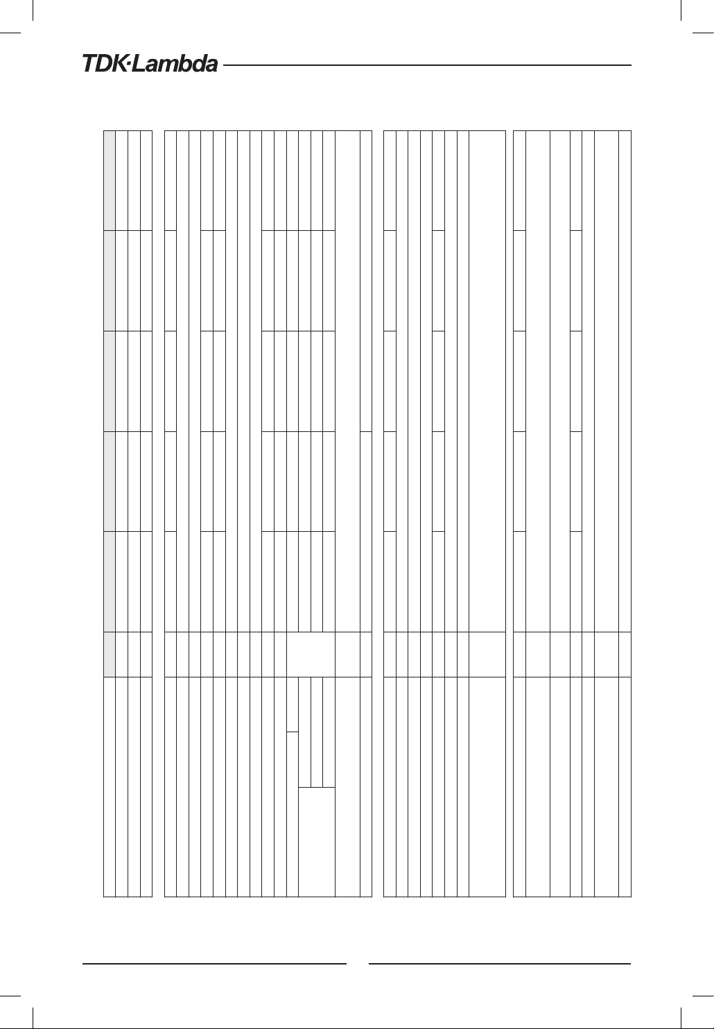
600 Series Specifications
+
2.3 Z
MODEL Z 10-60 20-30 36-18 60-10 100-6
1. Rated output voltage(*1) V 10 20 36 60 100
25 25 25 25 80
Output shut-down when power supply change mode from CV to CC or CC to CV. User presetable.
Reset by AC input recycle in autostart mode or by OUTPUT button or by rear panel ENABLE, or by communication port.
PROTECTIVE FUNCTIONS Z 10-60 20-30 36-18 60-10 100-6
Inverter Shut down method. Reset by AC input recycle in autostart mode or by OUTPUT button or by rear panel ENABLE,
or by communication port.
Output shut-down when power supply output voltage goes below UVP programming. User presetable.
Reset by AC input recycle in autostart mode or by OUTPUT button or by rear panel ENABLE, or by communication port.
1. Foldback protection ---
2. Over-voltage protection (OVP) ---
3. Over -voltage trip point V 0.5~12 1~24 2~40 5~66 5~110
4. Output under voltage limit (UVL) --- Preset by front panel or communication port. Prevents from adjusting Vout below limit. Does not affect in analog programming.
5. Output under voltage protection (UVP) ---
6. Over temperature protection --- User Selectable. Latched or non latched.
10V Model: Less than +/-0.3% of rated output current over 30 minutes following power on.
20V, 36V Model: Less than +/-0.15% of rated output current over 30 minutes following power on.
Time for output voltage to recover within 0.5% of its rated output for a load change 10~90% of rated output current.
Output set-point: 10~100%, Local sense. Less than 1mS, for models up to and including 100V
mS
Full load (*9)
No load (*10) (*15)(*17) 65 110 155 175 375
No load (*10) (*16)(*17) 280 470 470 500 1200
Time delay (*17) 285 425 450 570 1370
1. Max. Line regulation (*6) --- 0.01% of rated output voltage+2mV
2. Max. Load regulation (*7) --- 0.01% of rated output voltage+2mV
3. Ripple and noise (p-p, 20MHz) (*8) mV 50 50 50 50 80
4. Ripple r.m.s. 5Hz~1MHz mV 5 5 5 12 15
CONSTANT VOLTAGE MODE Z 10-60 20-30 36-18 60-10 100-6
2. Rated output current (*2) A 60 30 18 10 6
3. Rated output power W 600 600 648 600 600
5. Temperature coefficient PPM/°C 30PPM/°C from rated output voltage, following 30 minutes warm-up.
9. Up-prog. Response time, 0~Vomax.(*9) mS 50 50 50 50 100
6. Temperature stability --- 0.05% of rated Vout over 8hrs. interval following 30 minutes warm-up. Constant line, load & temp.
7. Warm-up drift --- Less than 0.05% of rated output voltage+2mV over 30 minutes following power on.
8. Remote sense compensation/wire V 1 1 2 3 5
10. Down-prog. response time:
11. Transient response time mS
1. Max. Line regulation (*6) --- 0.01% of rated output current+2mA
2. Max. Load regulation (*11) --- 0.01% of rated output current+5mA
3. Load regulation thermal drift --- Less than 0.15% of rated output current over 30 minutes following load change.
4. Ripple r.m.s. 5Hz~1MHz (*12) mA 150 75 25 8 5
12. Hold-up time (*18) --- 15mSec Typical. 20mSec Typical.
CONSTANT CURRENT MODE Z 10-60 20-30 36-18 60-10 100-6
5. Temperature coefficient PPM/°C 100PPM/°C from rated output current, following 30 minutes warm-up.
60V, 100V Models: Less than +/-0.1% of rated output current over 30 minutes following power on.
6. Temperature stability --- 0.05% of rated Iout over 8hrs. interval following 30 minutes warm-up. Constant line, load & temperature.
7. Warm-up drift ---
24
Page 25
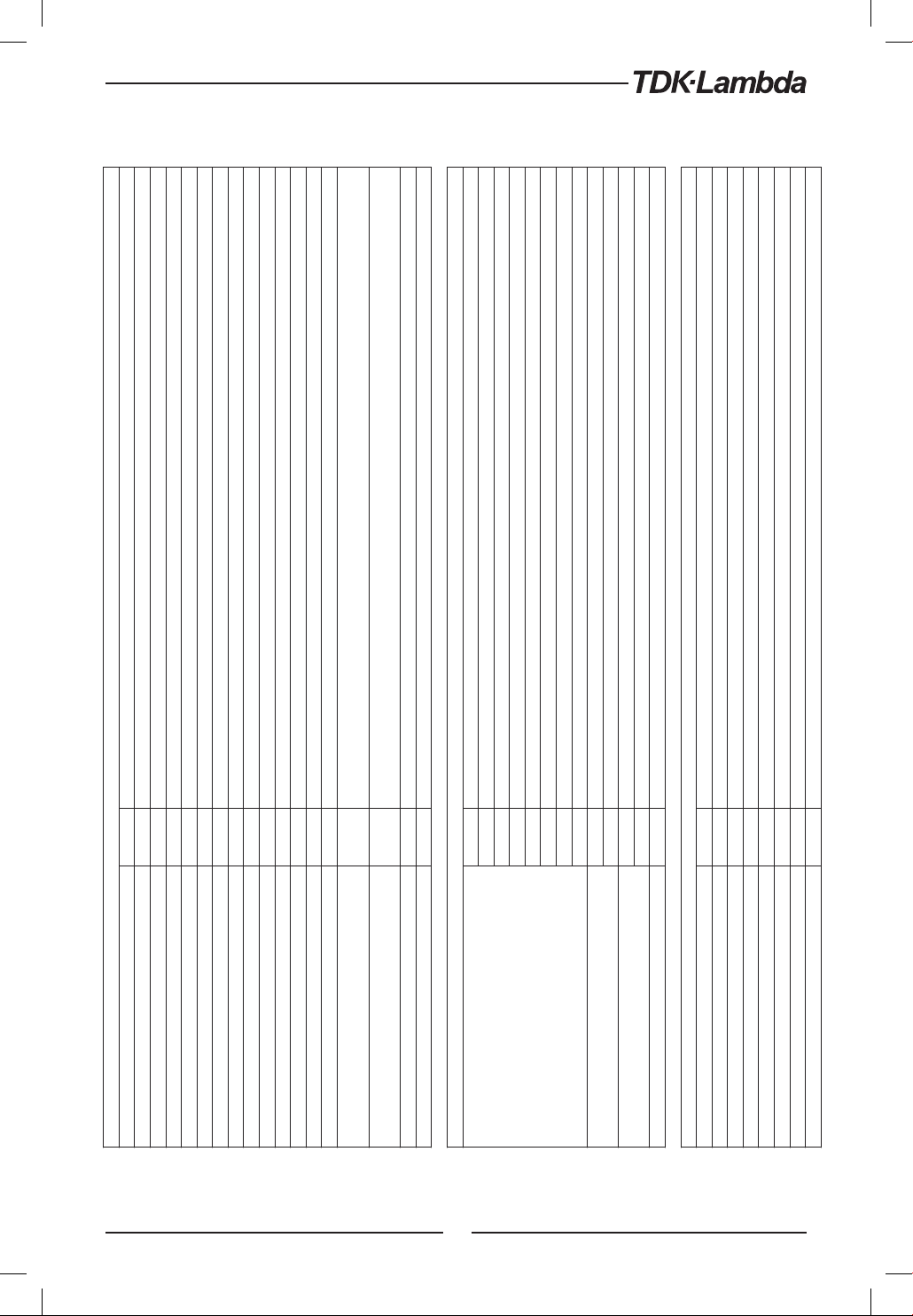
ANALOG PROGRAMMING AND MONITORING
1. Vout voltage programming --- 0~100%, 0~5V or 0~10V, user selectable. Accuracy and linearity: +/-0.5% of rated Vout.
Enables/Disables the PS output by dry contact (Short: On, Open: Off, Source current: less than 0.5mA). Ena/Dis is activated by front panel.
Maximum low level output =0.8V, Minimum high level output =3.8V, Maximum high level output =5V,
Maximum source current =16mA, pulse =20μs Typical.
Maximum low level input =1.2V, Minimum high level input =3.5V, Maximum high level input =5V, Maximum sink current =16mA,
positive edge, trigger: tw =10μs minimum, Tr/Tf =1μs maximum.
--- Multiple options with 2 Encoders
--- Vout/Iout manual adjust
--- OVP/UVL /UVP manual adjust
--- Protection Functions - OVP, UVL, UVP, Foldback, OCP, INT, SO
--- Communication Functions - Selection of LAN,IEEE (*19), RS232,RS485,USB
--- Communication Functions - Selection of Baud Rate, Address
--- Analog Control Functions - Selection Voltage/resistive programming, 5V/10V, 5K/10K programming
--- Analog Control Functions - Selection of Voltage/Current Monitoring 5V/10V, Output ON/OFF, Front Panel Lock.
--- Vout: 4 digits, accuracy: 0.5% of rated output voltage+/-1 count.
--- Iout: 4 digits, accuracy: 0.5% of rated output current+/-1 count.
--- GREEN LEDs: FINE, MENU, PREV, PROT, REM, OUTPUT, CV, CC
--- RED LED: PROT (OVP, UVP, OTP, FOLD, AC FAIL).
--- FINE, MENU, PREV, PROT, REM, OUTPUT
2. Iout voltage programming (*13) --- 0~100%, 0~5V or 0~10V, user selectable. Accuracy and linearity: +/-1% of rated Iout.
3. Vout resistor programming --- 0~100%, 0~5/10Kohm full scale, user selectable. Accuracy and linearity: +/-1% of rated Vout.
4. Iout resistor programming (*13) --- 0~100%, 0~5/10Kohm full scale, user selectable. Accuracy and linearity: +/-1.5% of rated Iout.
5. Shut Off (SO) control --- By electrical Voltage: 0~0.6V/4~15V or dry contact, user selectable logic.
6. Output current monitor (*13) --- 0~5V or 0~10V, user selectable. Accuracy: +/-1%.
7. Output voltage monitor --- 0~5V or 0~10V, user selectable. Accuracy: +/-1%.
8. Power supply OK signal --- 4~5V-OK, 0V-Fail. 500ohm series resistance.
9. Parallel operation (*20) --- Possible, up to 6 units in master/slave mode with single wire current balance connection.
10. Series operation --- 2 identical units (with external diodes).
11. CV/CC indicator --- Open collector. CC mode: On, CV mode: Off. Maximum voltage: 30V, maximum sink current: 10mA
12. Interlock (ILC) control ---
13. Local/Remote mode Control --- By electrical signal or Open/Short: 0~0.6V or short: Remote, 2~15V or open: Local
14. Local/Remote mode Indicator --- Open collector (shunted by 36V zener). On (0~0.6V, 10mA sink current max.)-Remote. Off-Local (30V max.).
15.Trigger out ---
16.Trigger in ---
17. Programmed signal 1 --- Open collector, maximum voltage 25V, maximum sink current 100mA. (Shunted by 27V zener)
18. Programmed signal 2 --- Open collector, maximum voltage 25V, maximum sink current 100mA. (Shunted by 27V zener)
FRONT PANEL
1. Control functions
2. Display
3. Indications
4. Function buttons
PROGRAMMING AND READBACK (RS232/485,USB, Optional: IEEE(*19), LAN)
1. Vout programming accuracy --- 0.05% of rated output voltage
2. Iout programming accuracy (*13) --- 0.1% of actual +0.1% of rated output current
3. Vout programming resolution --- 0.012% of full scale
4. Iout programming resolution --- 0.012% of full scale
5. Vout readback accuracy --- 0.05% of rated output voltage
6. Iout readback accuracy (*13) --- 0.1% of actual +0.3% of rated output current
7. Vout readback resolution --- 0.012% of full scale
8. Iout readback resolution --- 0.012% of full scale
25
Page 26
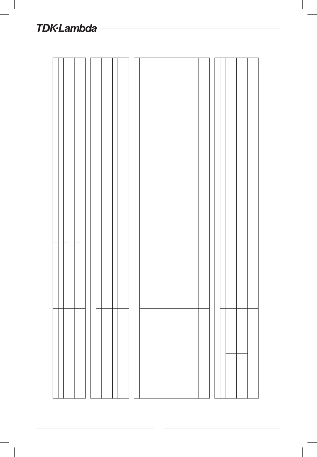
600 Series Specifications
+
Z
10-60 20-30 36-18 60-10 100-6
Z
1. Input voltage/freq. (*3) --- 85~265Vac continuous, 47~63Hz, single phase
2. Maximum Input current 100/200VAC (*4) --- 7.48/3.69 7.22/3.56 7.70/3.80 7.13/3.52 7.13/3.52
INPUT CHARACTERISTICS
5. Inrush current (*5) --- Less than 30A
3. Power Factor (Typ) --- 0.99 at 100, 0.98 at 200Vac, 100% load
4. Efficiency (Typ) 100/200VAC (*4) % 81/83 84/86 85/87 85/87 85/87
ENVIRONMENTAL CONDITIONS
1. Operating temperature --- 0~50°C, 100% load.
2. Storage temperature --- -20~85°C
3. Operating humidity % 20~90% RH (no condensation).
4. Storage humidity % 10~95% RH (no condensation).
Maximum 3000m. Derate ambient temp above 2000m.
Operating: Maximum ambient temperature, From 2000m up to 3000m Ambient temperature 40°C.
5. Altitude ---
UL61010-1, EN61010-1, IEC61010-1. Design to meet UL60950-1, EN60950-1
10V≤Vout≤60V: Output,J1,J2,J3,J4,USB,LAN,IEEE/ISOLATED Analog are Non Hazardous
Vout=100V:Output,J1,J2 are Hazardous J3,J4,USB, IEEE/ISOLATED Analog ,LAN are Non Hazardous
10Vout36V models: Input-Output&J1, J2, J3, J4, USB, LAN/IEEE/ISOLATED ANALOG: 4242VDC/1min; Input-Ground: 2828VDC/1min.
Output&J1, J2, J3, J4, USB, LAN/IEEE/ISOLATED ANALOG-Ground: 707VDC/1min.
60V,100V models: Input-Output&J1,J2: 4242VDC/1min; Input-J3,J4,USB,LAN/IEEE/ISOLATED Analog: 4242VDC/1min; Input-Ground:
2828VDC/1min.
Safety ---
EMC --- IEC/EN61326-1 (Built to meet EN55022/EN55024)
SAFETY/EMC
1. Applicable standards:
2. Withstand voltage ---
26
Output&J1, J2- J3, J4, USB, LAN/IEEE/ISOLATED ANALOG: 1910VDC/1min; Output&J1, J2-Ground: 1380VDC/1min.
J3, J4, USB/LAN/IEEE/ISOLATED ANALOG - Ground: 707VDC/1min;
3. Insulation resistance --- More than 100Mohm at 25°C, 70%RH.
4. Conducted emission --- IEC/EN61326-1 Industrial Location - B, FCC part 15-B, VCCI-B
5. Radiated emission --- IEC/EN61326-1 Industrial Location - A, FCC part 15-A, VCCI-A
MECHANICAL
Less than 2.1Kg.
STANDARD Kg
1. Cooling --- Forced air cooling by internal fan.
Less than 2.6Kg. Wide body with Isolated analog or Binding post or IEEE.
H: 83, W: 70, D: 350 (excluding bus bars, handles…). (Refer to Outline drawing)
H: 83, W: 105, D: 350 (excluding bus bars, handles…). (Refer to Outline drawing)
WIDE BODY Kg
STANDARD mm
WIDE BODY mm
2. Weight
3. Dimensions (WxHxD)
4. Vibration --- According to: IEC60068-2-64
5. Shock --- Less than 20G, half sine, 11mS. Unit is unpacked. According to: IEC60068-2-27
Page 27

NOTES:
*1: Minimum voltage is guaranteed to maximum 0.1% of rated output voltage.
*2: Minimum current is guaranteed to maximum 0.2% of rated output current.
*3: For cases where conformance to various safety standards (UL, IEC, etc…) is required, to be described as 100-240Vac (50/60Hz).
*4: Ta=25C with rated output power.
*5: Not including EMI filter inrush current, less than 0.2mSec.
*6: At 85~132Vac or 170~265VAC, constant load .
*7: From No-Load to Full-Load, constant input voltage. Measured at the sensing point in Remote Sense.
*8: Measured with JEITA RC-9131A (1:1) probe .
*9: From 10% to 90% or 90% to 10% of Rated output Voltage, with rated resistive load.
*10: From 90% to 10% of Rated output Voltage.
*11: For load voltage change, equal to the unit voltage rating, constant input voltage.
*12: For 10V model the ripple is measured at 2V to rated output voltage and rated output current. For other models, the ripple is measured at 10~100%
of rated output voltage and rated output current.
*13: The Constant Current programming, readback and monitoring accuracy do not include the warm-up and Load regulation thermal drift.
*14: Measured with JEITA RC-9131A (1:1) probe.
*15: For cases where the time interval between each down programming is longer than Td (time delay).
*16: For cases where the time interval between each down programming is shorter than Td (time delay).
*17: Td typical Minimum time between consecutive down programming cycles .
*18: At rated output power.
*19: Max. ambient temperature for using IEEE is 45°C
*20: For Parallel operation more than 2 units 5% of total output current is required.
27
Page 28
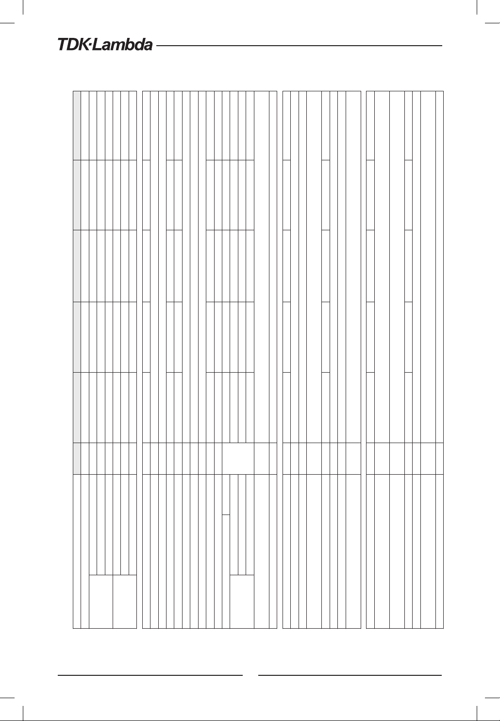
800 Series Specifications
25 25 25 25 80
Output shut-down when power supply change mode from CV to CC or CC to CV. User presetable.
Reset by AC input recycle in autostart mode or by OUTPUT button or by rear panel ENABLE, or by communication port.
For 10V: Less than 0.15% of rated output current over 30 minutes following load change.
Time for output voltage to recover within 0.5% of its rated output for a load change 10~90% of rated output current.
Output set-point: 10~100%, Local sense. Less than 1mS, for models up to and including 100V
A 66 36 20 12.5 7.5
W 660 720 720 750 750
85Vac ≤ Vin < 100Vac, Ta ≤ 40°C A 72 40 24 14 8
Vin ≥ 100Vac, Ta ≤ 50°C W 720 800 864 840 800
85Vac ≤ Vin < 100Vac, 40°C < Ta ≤ 50°C
85Vac ≤ Vin < 100Vac, Ta ≤ 40°C W 720 800 864 840 800
85Vac ≤ Vin < 100Vac, 40°C < Ta ≤ 50°C
Vin ≥ 100Vac, Ta ≤ 50°C A 72 40 24 14 8
mS
Time delay (*17) 285 425 450 570 1370
No load (*10) (*15) (*17) 65 110 155 175 375
No load (*10) (*16) (*17) 280 470 470 500 1200
For 20V ~ 100V: Less than 0.1% of rated output current over 30 minutes following load change.
10V model: Less than +/-0.3%, 20V model: Less than +/-0.15%, 36V~100 models: Less than +/-0.1% of rated output current over
30 minutes following power on.
Inverter Shut down method. Reset by AC input recycle in autostart mode or by OUTPUT button or by rear panel ENABLE,
or by communication port.
Output shut-down when power supply output voltage goes below UVP programming. User presetable.
Reset by AC input recycle in autostart mode or by OUTPUT button or by rear panel ENABLE, or by communication port.
+
1. Foldback protection ---
2.4 Z
MODEL Z 10-72 20-40 36-24 60-14 100-8
1. Rated output voltage(*1) V 10 20 36 60 100
2. Rated output
current (*2)(*21)
3. Rated output
power
1. Max. Line regulation (*6) --- 0.01% of rated output voltage+2mV
2. Max. Load regulation (*7) --- 0.01% of rated output voltage+2mV
CONSTANT VOLTAGE MODE Z 10-72 20-40 36-24 60-14 100-8
1. Max. Line regulation (*6) --- 0.01% of rated output current+2mA
2. Max. Load regulation (*11) --- 0.01% of rated output current+5mA
3. Load regulation thermal drift ---
4. Ripple r.m.s. 5Hz~1MHz (*12) mA 180 100 31 28 12
5. Temperature coefficient PPM/°C 100PPM/°C from rated output current, following 30 minutes warm-up.
6. Temperature stability --- 0.05% of rated Iout over 8hrs. interval following 30 minutes warm-up. Constant line, load & temperature.
11. Transient response time mS
12. Hold-up time (*18) --- 10mSec Typical. Rated output power.
10. Down-prog. response time: Full load (*9)
3. Ripple and noise (p-p, 20MHz) (*8) mV 50 50 50 60 80
4. Ripple r.m.s. 5Hz~1MHz mV 5 5 5 12 15
5. Temperature coefficient PPM/°C 30PPM/°C from rated output voltage, following 30 minutes warm-up.
9. Up-prog. Response time, 0~Vomax.(*9) mS 50 50 50 50 100
6. Temperature stability --- 0.05% of rated Vout over 8hrs. interval following 30 minutes warm-up. Constant line, load & temp.
7. Warm-up drift --- Less than 0.05% of rated output voltage+2mV over 30 minutes following power on.
8. Remote sense compensation/wire V 1 1 2 3 5
CONSTANT CURRENT MODE Z 10-72 20-40 36-24 60-14 100-8
7. Warm-up drift ---
28
PROTECTIVE FUNCTIONS Z 10-72 20-40 36-24 60-14 100-8
2. Over-voltage protection (OVP) ---
3. Over - voltage trip point V 0.5~12 1~24 2~40 5~66 5~110
4. Output under voltage limit (UVL) --- Preset by front panel or communication port. Prevents from adjusting Vout below limit. Does not affect in analog programming.
5. Output under voltage protection (UVP) ---
6. Over temperature protection --- User Selectable. Latched or non latched
Page 29
ANALOG PROGRAMMING AND MONITORING
1. Vout voltage programming --- 0~100%, 0~5V or 0~10V, user selectable. Accuracy and linearity: +/-0.5% of rated Vout.
Enables/Disables the PS output by dry contact (Short: On, Open: Off, Source current: less than 0.5mA). Ena/Dis is activated by front panel.
Maximum low level output =0.8V, Minimum high level output =3.8V, Maximum high level output =5V,
Maximum source current =16mA, pulse =20μs Typical.
Maximum low level input =1.2V, Minimum high level input =3.5V, Maximum high level input =5V, Maximum sink current =16mA,
positive edge, trigger: tw =10μs minimum, Tr/Tf =1μs maximum.
--- Multiple options with 2 Encoders
--- Vout/Iout manual adjust
--- OVP/UVL /UVP manual adjust
--- Protection Functions - OVP, UVL, UVP, Foldback, OCP, INT, SO
--- Communication Functions - Selection of LAN,IEEE (*19) ,RS232,RS485,USB
--- Communication Functions - Selection of Baud Rate, Address
--- Analog Control Functions - Selection Voltage/resistive programming, 5V/10V, 5K/10K programming
--- Analog Control Functions - Selection of Voltage/Current Monitoring 5V/10V, Output ON/OFF, Front Panel Lock.
--- Vout: 4 digits, accuracy: 0.5% of rated output voltage+/-1 count.
--- Iout: 4 digits, accuracy: 0.5% of rated output current+/-1 count.
--- GREEN LEDs: FINE, MENU, PREV, PROT, REM, OUTPUT, CV, CC
--- RED LED: PROT (OVP, UVP, OTP, FOLD, AC FAIL).
2. Iout voltage programming (*13) --- 0~100%, 0~5V or 0~10V, user selectable. Accuracy and linearity: +/-1% of rated Iout.
3. Vout resistor programming --- 0~100%, 0~5/10Kohm full scale, user selectable. Accuracy and linearity: +/-1% of rated Vout.
4. Iout resistor programming (*13) --- 0~100%, 0~5/10Kohm full scale, user selectable. Accuracy and linearity: +/-1.5% of rated Iout.
5. Shut Off (SO) control --- By electrical Voltage: 0~0.6V/4~15V or dry contact, user selectable logic.
6. Output current monitor (*13) --- 0~5V or 0~10V, user selectable. Accuracy: +/-1%.
7. Output voltage monitor --- 0~5V or 0~10V, user selectable. Accuracy: +/-1%.
8. Power supply OK signal --- 4~5V-OK, 0V-Fail. 500ohm series resistance.
9. Parallel operation (*20) --- Possible, up to 6 units in master/slave mode with single wire current balance connection.
10. Series operation --- 2 identical units (with external diodes).
11. CV/CC indicator --- Open collector. CC mode: On, CV mode: Off. Maximum voltage: 30V, maximum sink current: 10mA
12. Interlock (ILC) control ---
13. Local/Remote mode Control --- By electrical signal or Open/Short: 0~0.6V or short: Remote, 2~15V or open: Local
14. Local/Remote mode Indicator --- Open collector (shunted by 36V zener). On (0~0.6V, 10mA sink current max.)-Remote. Off-Local (30V max.).
15.Trigger out ---
16.Trigger in ---
17. Programmed signal 1 --- Open collector, maximum voltage 25V, maximum sink current 100mA. (Shunted by 27V zener)
18. Programmed signal 2 --- Open collector, maximum voltage 25V, maximum sink current 100mA. (Shunted by 27V zener)
FRONT PANEL
1. Control functions
2. Display
3. Indications
4. Function buttons --- FINE, MENU, PREV, PROT, REM, OUTPUT
PROGRAMMING AND READBACK (RS232/485,USB, Optional: IEEE(*20), LAN)
1. Vout programming accuracy --- 0.05% of rated output voltage
2. Iout programming accuracy (*13) --- 0.1% of actual +0.1% of rated output current
3. Vout programming resolution --- 0.012% of full scale
4. Iout programming resolution --- 0.012% of full scale
5. Vout readback accuracy --- 0.05% of rated output voltage
6. Iout readback accuracy (*13) --- 0.1% of actual +0.3% of rated output current
7. Vout readback resolution --- 0.012% of full scale
8. Iout readback resolution --- 0.012% of full scale
29
Page 30
800 Series Specifications
+
Z
3. Power Factor (Typ) --- 0.99 at 100Vac, 100% load / 0.98 at 200Vac, 100% load
1. Input voltage/freq. (*3) --- 85~265Vac continuous, 47~63Hz, single phase
2. Maximum Input current 100/200VAC (*4) --- 9.00/4.45 9.65/4.75 10.30/5.10 10.00/4.95 9.50/4.7
INPUT CHARACTERISTICS Z 10-72 20-40 36-24 60-14 100-8
5. Inrush current (*5) --- Less than 30A
4. Efficiency (Typ) 100/200VAC (*4) % 81/83 84/86 85/87 85/87 85/87
ENVIRONMENTAL CONDITIONS
1. Operating temperature --- 0~50°C, 100% load.
2. Storage temperature --- -20~85°C
3. Operating humidity % 20~90% RH (no condensation).
Maximum 3000m.
From 2000m up to 3000m, max. Ambient temperature 40°C and rated output current according to the table below:
Z 10-72 20-40 36-24 60-14 100-8
---
4. Storage humidity % 10~95% RH (no condensation).
5. Altitude
UL61010-1, EN61010-1, IEC61010-1. Design to meet UL60950-1, EN60950-1
10V≤Vout≤60V: Output,J1,J2,J3,J4,USB,LAN,IEEE/ISOLATED Analog are Non Hazardous
Vout=100V:Output,J1,J2 are Hazardous J3,J4,USB, IEEE/ISOLATED Analog ,LAN are Non Hazardous
10≤Vout≤36V models: Input-Output&J1,J2,J3,J4,USB,LAN/IEEE/ISOLATED ANALOG: 4242VDC/1min; Input-Ground: 2828VDC/1min.
Output&J1,J2,J3,J4,USB,LAN/IEEE/ISOLATED ANALOG-Ground: 707VDC/1min.
60V,100V models: Input-Output&J1,J2: 4242VDC/1min; Input-J3,J4,USB,LAN/IEEE/ISOLATED Analog: 4242VDC/1min; Input-Ground: 2828VDC/1min.
Output & J1,J2- J3,J4,USB,LAN/IEEE/ISOLATED ANALOG :1910VDC/1min; Output&J1,J2-Ground: 1380VDC/1min.
J3, J4, USB/LAN/IEEE/ISOLATED ANALOG - Ground: 707VDC/1min;
Safety ---
EMC --- IEC/EN61326-1 (Built to meet EN55022/EN55024)
STANDARD Kg Less than 2.1Kg.
WIDE BODY Kg Less than 2.6Kg. Wide body with Isolated analog or Binding post or IEEE
STANDARD mm H: 83, W: 70, D: 350 (excluding bus bars, handles…). (Refer to Outline drawing)
WIDE BODY mm H: 83, W: 105, D: 350 (excluding bus bars, handles…). (Refer to Outline drawing)
Rated output current at 100≤Vin≤265Vac A 72 40 24 14 8
Rated output current at 85≤Vin<100Vac A 66 36 20 12.5 7.5
SAFETY/EMC
1. Applicable standards:
2. Withstand voltage ---
3. Insulation resistance --- More than 100Mohm at 25°C, 70%RH.
4. Conducted emission --- IEC/EN61326-1 Industrial Location - B, FCC part 15-B, VCCI-B
5. Radiated emission --- IEC/EN61326-1 Industrial Location - A, FCC part 15-A, VCCI-A
MECHANICAL
1. Cooling --- Forced air cooling by internal fan
2. Weight
3. Dimensions (WxHxD)
4. Vibration --- According to: IEC60068-2-64
5. Shock --- Less than 20G, half sine, 11mS. Unit is unpacked. According to: IEC60068-2-27
NOTES:
*1: Minimum voltage is guaranteed to maximum 0.1% of rated output voltage.
*2: Minimum current is guaranteed to maximum 0.2% of rated output current.
*3: For cases where conformance to various safety standards (UL, IEC, etc…) is required, to be described as 100-240Vac (50/60Hz).
*4: Ta=25°C with rated output power.
30
Page 31
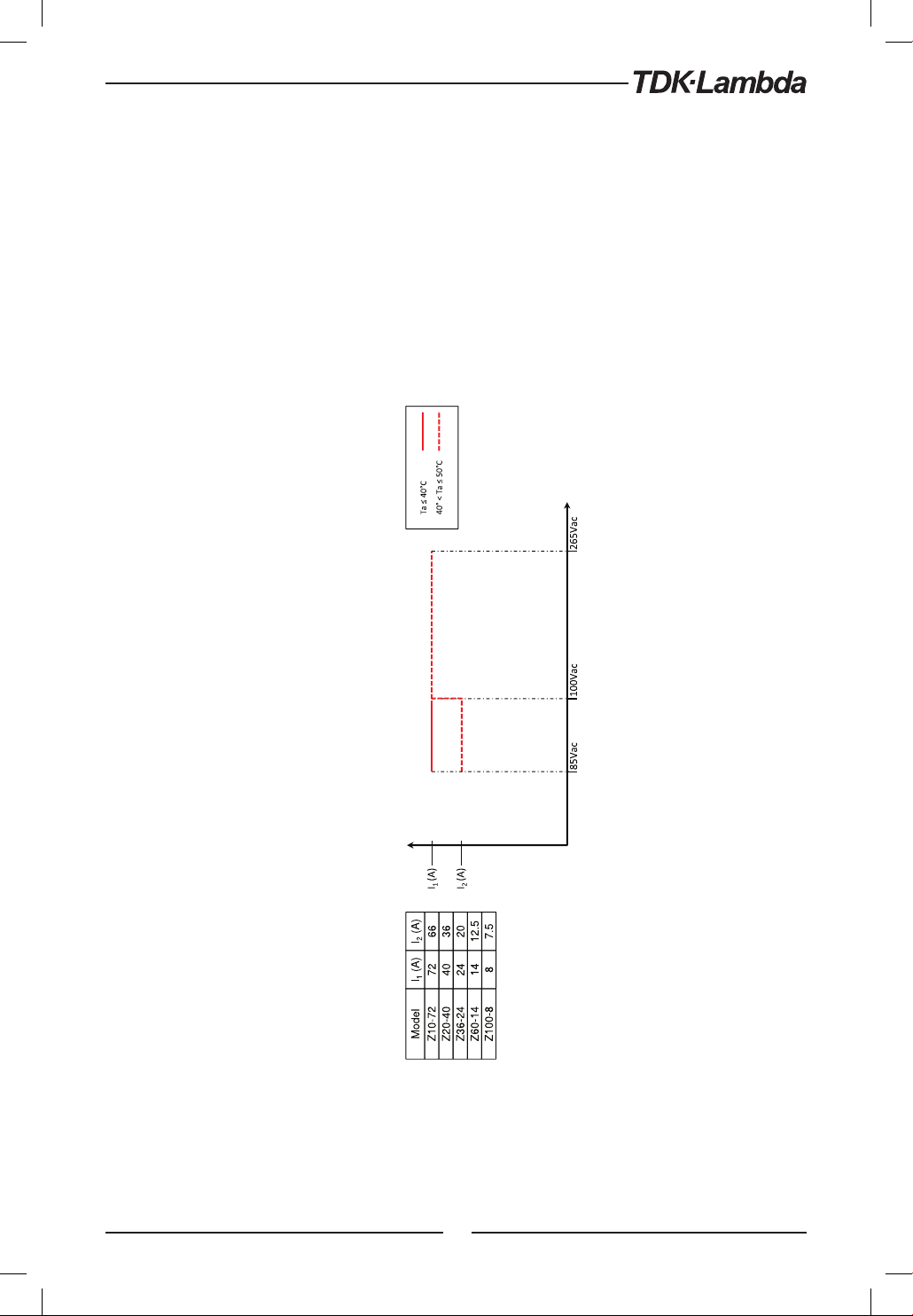
The supplemental characteristics are useful in assessing applications for the power supply. Several kinds of supplemental characteristics are listed below.
The supplemental characteristics data is held in each TDK-Lambda sales and service facility. For further details please contact the TDK-Lambda office near you.
800 Rated Output Current Vs. Line Voltage and Ambient Temperature
+
Fig. 2-1: Z
*5: Not including EMI filter inrush current, less than 0.2mSec.
*6: At 85~132Vac or 170~265VAC, constant load.
*7: From No-Load to Full-Load, constant input voltage. Measured at the sensing point in Remote Sense.
*8: Measured with JEITA RC-9131A (1:1) probe.
*9: From 10% to 90% or 90% to 10% of Rated Output Voltage, with rated resistive load.
*10: From 90% to 10% of Rated Output Voltage.
*11: For load voltage change, equal to the unit voltage rating, constant input voltage.
*12: For 10V model the ripple is measured at 2V to rated output voltage and rated output current. For other models, the ripple is measured at 10~100%
of rated output voltage and rated output current.
*13: The Constant Current programming, readback and monitoring accuracy do not include the warm-up and Load regulation thermal drift.
*14: Measured with JEITA RC-9131A (1:1) probe.
*15: For cases where the time interval between each down programming is longer than Td (time delay).
*16: For cases where the time interval between each down programming is shorter than Td (Time delay).
*17: Td typical Minimum time between consecutive down programming cycles.
*18: At rated output power.
*19: Max. ambient temperature for using IEEE is 45°C
*20: For Parallel operation more than 2 units 5% of toatal output current is requierd.
*21: Refer to Fig.2-1 below
2.5 Supplemental Characteristics
The supplemental characteristics give typical but non-warranted performance characteristics.
1. Evaluation Data: Typical performance of the power supply.
2. Reliability Data: Reliability performance of the power supply.
3. IEC61000 Data: Performance of the power supply under IEC61000 test conditions.
4. EMI Data: Typical EMI (conducted and radiated) performance of the power supply.
31
Page 32
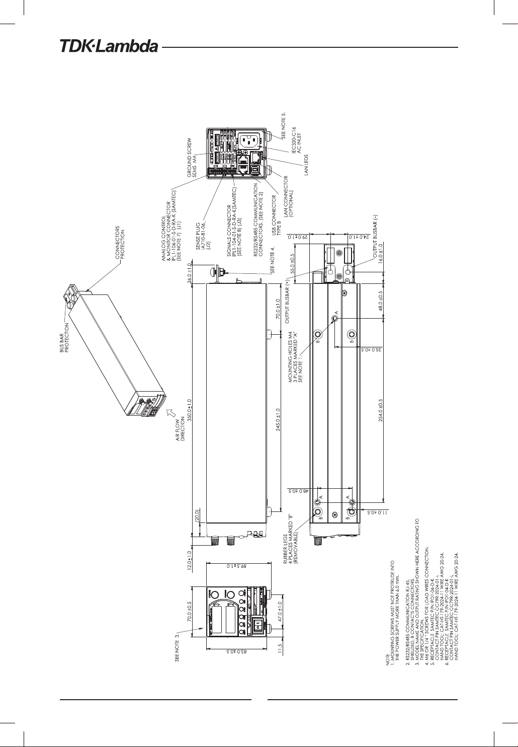
2.6 Z200W/400W/600W/800W Outline Drawing
32
TIGHTENING TORQUE MUST BE MAX. 0.58Nm
Page 33
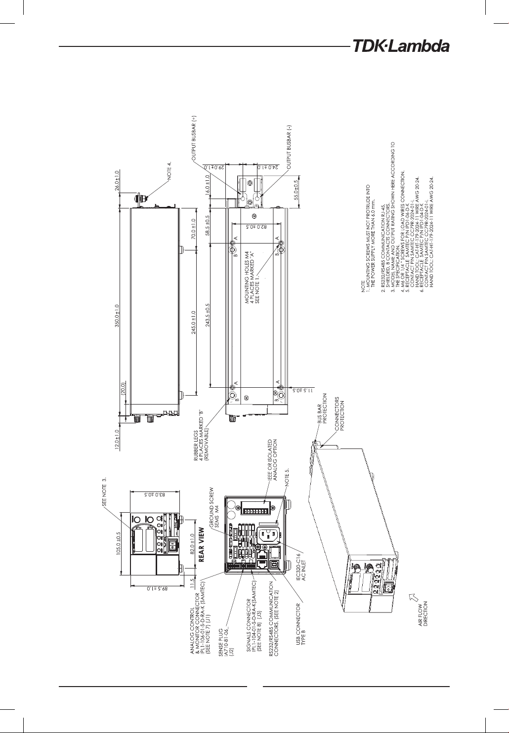
2.7 Z200W/400W/600W/800W Optional IEEE, Isolated Analog Interface Outline Drawing
TIGHTENING TORQUE MUST BE MAX. 0.58Nm
33
Page 34
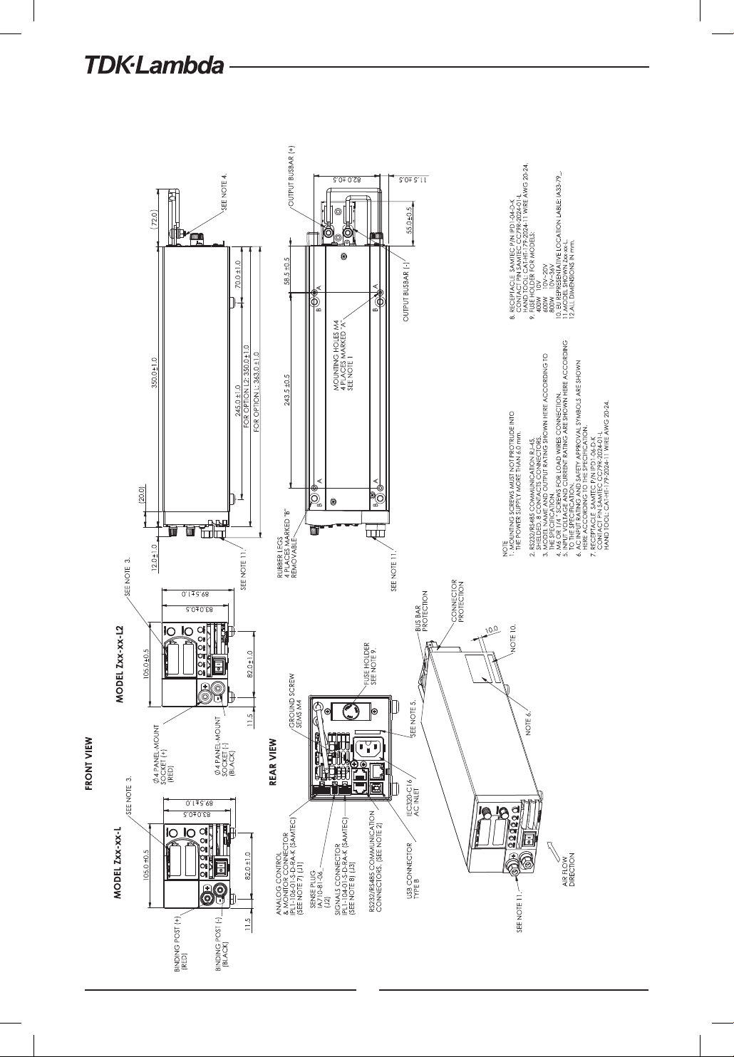
2.8 Z200W/400W/600W/800W Front Panel Output Binding Post/Socket Outline Drawing L/L2
TIGHTENING TORQUE MUST BE MAX. 0.58Nm
34
Page 35
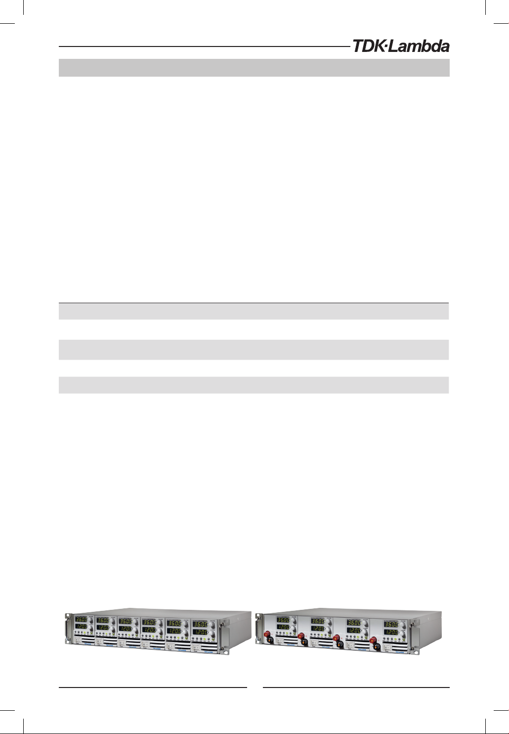
CHAPTER 3: INSTALLATION
3.1 General
This chapter contains instructions for initial inspection, preparation for use and repackaging for
shipment. Connection to PC, setting the communication port and linking Z+ power supplies are
described in Chapter 7.
NOTE:
Z+ power supplies generate magnetic fields which might affect the operation of other instruments.
If your equipment is susceptible to magnetic fields, do not position it adjacent to the power supply.
3.2 Preparation for Use
In order to be operational the power supply must be connected to an appropriate AC source. The
AC source voltage should be within the power supply specification. Do not apply power before
reading, Section 3.6 and 3.7.
Table 3-1 below, describes the basic setup procedure. Follow the instructions in Table 3-1 in the
sequence given to prepare the power supply for use.
Step no. Item Description Reference
1 Inspection Initial physical inspection of the power supply Section 3.3
2 Installation
3 AC source
4 Test Turn-on checkout procedure. Section 3.8
Installing the power supply,
Ensuring adequate ventilation.
AC source requirements
Connecting the power supply to the AC source.
Section 3.4
Section 3.5
Section 3.6
Section 3.7
5 Load connection Wire size selection. Local /Remote sensing. Section 3.9
6 Default setting Single or multiple loads. Section 7.2.1
Table 3-1: Basic setup procedure
3.3 Initial Inspection
Prior to shipment this power supply was inspected and found free of mechanical or electrical defects.
Upon unpacking of the power supply, inspect for any damage which may have occurred in transit.
The inspection should confirm that there is no exterior damage to the power supply such as broken
knobs or connectors and that the front panel and meter faces are not scratched or cracked. Keep
all packing material until the inspection has been completed. If damage is detected, file a claim
with carrier immediately and notify the TDK-Lambda sales or service facility nearest you.
3.4 Rack Mounting
The Z+ power supply series is designed to fit in a standard 19” 2U height rack.
Six units (70mm width) can be assembled into 19” 2U-rack. Refer to Fig.3-1.
Four units (105mm width) can be assembled into 19” 2U-rack. Refer to Fig.3-2
Fig.3-1 Fig.3-2
35
Page 36

3.5 Location, Mounting and Cooling
This power supply is fan cooled. The air intake is at the front panel and the exhaust is at the rear
panel. Upon installation allow cooling air to reach the front panel ventilation inlets. Allow minimum
10cm (4”) of unrestricted air space at the front and the rear of the unit.
The power supply should be used in an area that the ambient temperature does not exceed +50°C.
Standort, Montage und Kühlung
Dieses Netzgerät ist gebläsegekühlt, mit vorderseitiger Luftaufnahme und rückseitigem Luftausstoß.
Bei Installation ist darauf zu achten, dass die vorderseitigen Gebläseöffnungen ungehindert Luft
aufnehmen können. Dazu muss vor und hinter dem Gerät ein Abstand von mindestens 10 cm
zum nächsten Hindernis eingehalten werden. Das Netzgerät darf nur in einem Bereich benutzt
werden, in dem die Umgebungstemperatur +50 °C nicht übersteigt.
3.6 AC Source Requirements
The Z+ series can be operated from a nominal 100V to 240V, single phase, 47~63Hz. The input
voltage range and current required for each model is specified in Chapter 2. Ensure that under
heavy load, the AC voltage supplied to the power supply does not fall below the specifications
described in Chapter 2.
Netzstromanforderungen
Die Geräte der Z+ Serie können aus einem einphasigen Netzstromanschluss mit nominell 100-240 V
und 47-63 Hz versorgt werden. Der für jedes Modell erforderliche Bereich von Eingangsspannung
und Stromstärke ist in Kapitel 2 angeführt. Es ist sicherzustellen, dass der dem Netzgerät zugeführte
Netzstrom bei hoher Belastung nicht unter die in Kapitel 2 angeführten Werte fällt.
3.7 AC Input Power Connection
WARNING:
Some components inside the power supply are at AC voltage even when the On/Off switch is in
the ”Off” position. To avoid electric shock hazard, disconnect the line cord and load and wait two
minutes before removing cover.
WARNUNG:
Einzelne Komponenten im Netzteil stehen auch dann unter Spannung, wenn sich der
Ein-/Aus-Schalter in der ”Aus”-Position befindet. Um die Gefahr eines elektrischen Schlages zu
vermeiden, müssen vor Öffnen des Gerätes die Netzzuleitung und die Last getrennt werden. Warten
Sie dann zwei Minuten, bevor Sie das Gehäuse abnehmen.
3.7.1 AC Input Connector
An IEC connector is provided on the rear panel for connecting the unit to the AC power source with
an AC cord. The IEC connector also provides the safety ground connection while the AC cord is
plugged into an appropriate AC.
36
Page 37
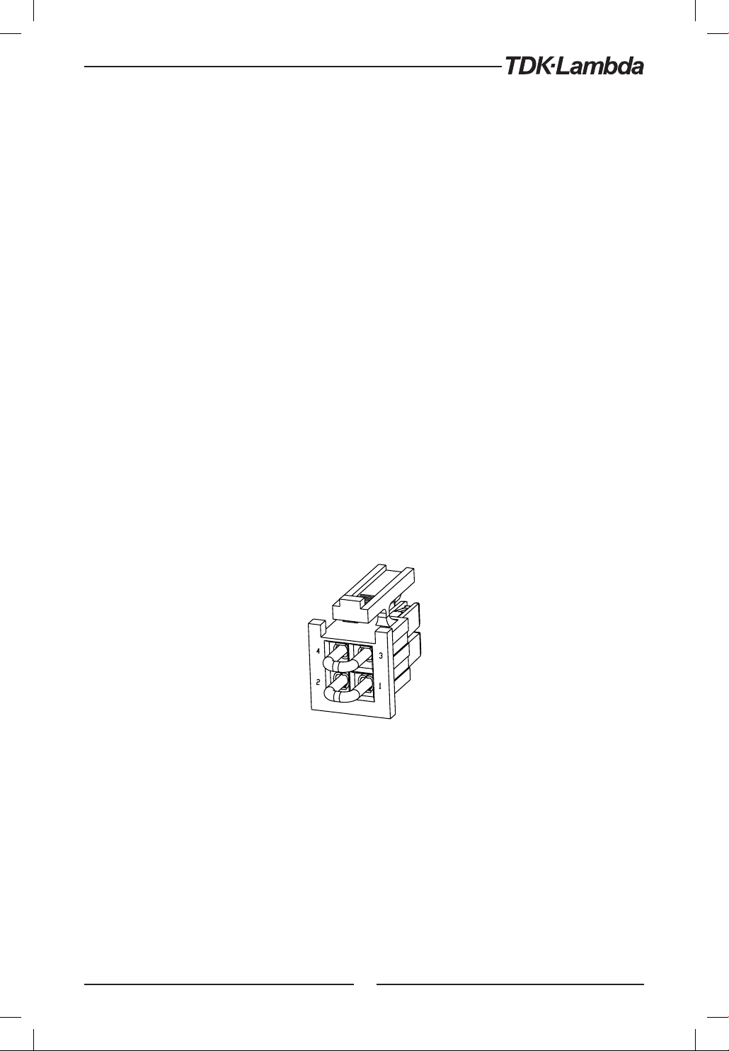
3.7.2 AC Input Cord
Refer to section 1.3.4 for details of the AC input cords recommended.
WARNING:
The AC input cord connector is the disconnect device of the power supply. The connector must be
readily identifiable and accessible to the user. The AC input cord must be no longer than 3m.
WARNUNG:
Die Stromversorgung wird durch Ziehen des Netzkabels aus der Steckdose vom Versorgungsnetz getrennt. Der
Netzanschluss muss für den Benutzer leicht erkennbar und jederzeit zugänglich sein. Das Netzkabel darf nicht
länger als drei Meter sein.
3.8 Turn-On Checkout Procedure
3.8.1 General
The following procedure ensures that the power supply is operational and may be used as a basic
incoming inspection check.
3.8.2 Prior to Operation
1. Ensure that the power supply is configured to the default setting:
AC On/Off switch at Off position.
Sense connector : Configured to Local Sense as shown in Fig.3-3:
1 Local (-) sense
2 (-) Sense
3 (+) Sense
4 Local (+) sense
Fig.3-3: Sense connector default connection
2. Ensure that the protection of output bus-bars or of output connector is mounted and properly
assembled for power supplies when the output voltage exceed 60VDC.
3. Connect the unit to an AC source as described in section 3.7.
4. Connect a DVM with appropriate cables for the rated voltage to the output terminals.
5. Turn the front panel AC power switch to On.
6. When power supply is turned ON the display shows ”” and all LEDs illuminate momentarily.
The power supply operating status is then displayed.
37
Plug P/N: IPD1-02-D-K
(SAMTEC)
Page 38

3.8.3 Constant Voltage Check
1. Turn on the output by pressing OUTPUT button so the OUTPUT LED illuminates.
2. Observe the power supply Voltage display and rotate the Voltage encoder.
Ensure that the output voltage varies while the Voltage encoder is rotated.
The minimum control range is from zero to the maximum rated output for the power supply
model. Compare the DVM reading with the front panel Voltage display to verify the accuracy
of the Voltage display. Ensure that the front panel CV LED illuminates.
3. Turn off the front panel AC power switch.
3.8.4 Constant Current Check
Ensure that the front panel AC power switch is at Off position and the DVM connected to the
output terminals shows zero voltage.
1. Connect DC shunt across the output terminals. Ensure that the shunt and the wires current
ratings are higher than the power supply rating. Connect a DVM to the shunt.
2. Turn the front panel AC power switch to On position.
3. Turn on the output by pressing OUTPUT button so the OUTPUT LED illuminates.
4. Observe the power supply Current display and rotate the Current encoder. Ensure that the
output current varies while the Current encoder is rotated. The minimum control range is from
zero to the maximum rated output for the power supply model. Compare the DVM reading
with the front panel Current display to verify the accuracy of the Current display. Ensure that
the front panel CC LED is on.
5. Turn off the front panel AC power switch.
6. Remove the shunt from the power supply output terminals.
3.8.5 OVP Check
Refer to Section 5.3.2 for explanation of the OVP function prior to performing the procedure below.
1. Turn the front panel AC power switch to On position and turn on the output by pressing
OUTPUT button.
2. Using the Voltage encoder, adjust the output voltage to approx. 10% of the unit voltage rating.
3. Set OVP to 50% of of the unit voltage rating.
4. Adjust the output voltage toward it’s maximum and check that the output voltage cannot
be increased more than the OVP setting.
5. Adjust OVP limit to the maximum.
3.8.6 UVL Check
The UVL can be set when the power supply output is Enabled (On) or Disabled (Off). UVL setting
values are limited at the maximum level to approximately 5% below the Output Voltage setting.
Attempting to adjust the value above this limit will result in no response to the adjustment attempt.
The minimum value setting is zero.
1. Press PROT button. PROT (GREEN) LED illuminates. Current display shows ”” message.
2. Press Current Encoder. Voltage Display shows ”” message, Current display shows setting level.
3. Rotate the Voltage encoder to set ””.
4. Rotate the Current encoder to adjust the level.
5. Press PROT button twice or wait 15 sec. to return display to its previous state and then PROT
LED turns OFF.
6. Adjust the output voltage toward it’s minimum and check that the output voltage cannot be
decreased below the UVL setting.
7. Adjust the UVL limit to the minimum.
38
Page 39

3.8.7 Foldback Check
WARNING:
There is a potential shock hazard when checking a power supply with output voltage greater than
60VDC. Observe proper safety procedures during the checking.
WARNUNG:
Beim Einsatz eines Netzteils mit einer Nenn-Ausgangsspannung von mehr als 60VDC besteht
Stromschlaggefahr. Beachten Sie bei der Überprüfung die entsprechenden Sicherheitsvorkehrungen.
Refer to Section 5.3.4 for explanation of the FOLD function prior to performing the procedure below.
1. Ensure that the output voltage is set to approx. 10% of the unit rating.
2. Adjust the Current encoder to set the current limit to approx. 10% of the unit rating.
3. Set Foldback to CC MODE.
4. Short the output terminals momentarily (approx. 0.5 sec.). Ensure that the output voltage falls
to zero, the Voltage display shows ”FOd ”, Current display shows ”FA I ” and the PROT red LED blinks.
5. Set Foldback to OFF. The output voltage remains zero.
6. Press OUTPUT button. Ensure that the output voltage returns to it’s last setting.
7. Turn the output off by pressing OUTPUT button. Ensure that the Voltage display shows ”
OFF
3.9 Connecting the Load
Turn off the AC input power before making or changing any rear panel connection. Ensure that
all connections are securely tightened before applying power. There is a potential shock hazard
when using a power supply with a rated output greater than 60VDC.
”.
WARNING:
There is a potential shock hazard when using a power supply with an output voltage greater than
60VDC. Turn off the AC input power before making or changing any rear panel connection.
Ensure that the protection of output bus-bars and output connectors is mounted and properly
assembled when output voltage exceed 60VDC. Ensure that all connections are securely tightened
before applying power.
WARNUNG:
Bei Einsatz einer Stromversorgung von über 60VDC Nennspannung besteht eine potentielle
Gesundheitsgefahr durch elektrischen Schlag. Schalten Sie die Stromversorgung AUS, bevor Sie Anschlüsse
auf der Rückseite vornehmen oder verändern. Stellen Sie sicher, dass die Schutzabdeckungen der
Ausgangs-Stromschienen und Ausgangsstecker zuverlässig montiert sind, wenn die Ausgangsspannung
60VDC übersteigt. Stellen Sie sicher, dass alle Verbindungen fest angezogen sind, bevor Sie das Gerät
mit Netzspannung verbinden.
3.9.1 Load Wiring
The following considerations should be made to select wiring for connecting the load to the
power supply:
• Current carrying capacity of the wire (refer to 3.9.2)
• Insulation rating of the wire should be at least equivalent to the maximum output voltage
of the power supply.
• Maximum wire length and voltage drop (refer to 3.9.2)
• Noise and impedance effects of the load wiring (refer to 3.9.4).
39
Page 40
3.9.2 Current Carrying Capacity
Two factors must be considered when selecting the wire size:
1. Wires should be at least heavy enough not to overheat while carrying the power supply load
current at the rated load, or the current that would flow in the event the load wires were
shorted, whichever is greater.
2. Wire size should be selected to enable voltage drop per lead to be less than 1.0V at the rated
current. Although units will compensate higher voltage drop in each load wire (refer to the
specifications). It is recommended to minimize the voltage drop (1V maximum) to prevent
excessive output power consumption from the power supply and poor dynamic response
to load changes. Please refer to Tables 3-2 and 3-3 for maximum wire length to limit voltage
drop in American and European dimensions respectively.
Wire size
AWG
14 2.526 80 40 20 8 5
12 1.589 120 60 30 12 7.5
10 0.9994 200 100 50 20 12.5
8 0.6285 320 160 80 32 20
6 0.3953 500 250 125 50 31
4 0.2486 800 400 200 80 50
2 0.1564 1200 600 300 125 78
Resistivity
Ohm/1000ft
Maximum length in feet to limit
voltage drop to 1V or less
5A 10A 20A 50A 80A
Table 3-2: Maximum wire length for 1V drop on lead (in feet)
Cross sect.
area
(mm2)
2.5 8.21 24.0 12 6 2.4 1.5
4 5.09 39.2 18.6 9.8 4 2.5
6 3.39 59.0 29.4 14.8 5.8 3.6
10 1.95 102.6 51.2 25.6 10.2 6.3
16 1.24 160.0 80 40 16 10
25 0.795 250.0 125 62 25.2 15.7
35 0.565 354.0 177 88 35.4 22
Resistivity
Ohm/Km
Maximum length in meters to limit
voltage drop to 1V or less
5A 10A 20A 50A 80A
Table 3-3: Maximum wire length for 1V drop on lead (in meters)
For currents not shown in Table 3-2 and 3-3, use the formula:
Maximum length=1000/(current x resistivity)
Where current is expressed in amperes and resistivity in ohms/km or ohms/1000ft.
40
Page 41

3.9.3 Wire Termination
The wires should be properly terminated with terminals securely attached. DO NOT use non
terminated wires for load connection at the power supply.
CAUTION:
When local sensing, a short from +LS or +S to -V or -S or -LS, will cause damage to the power supply.
Reversing the sense wires might cause damage to the power supply in local and remote sensing.
(Do not connect -S to +V or +S to -V.)
3.9.4 Noise and Impedance Effects
To minimize the noise pickup or radiation, the load wires and remote sense wires should be twisted
pairs to the shortest possible length. Shielding of sense leads may be necessary in high noise
environments. Where shielding is used, connect the shield to the chassis via a rear panel Ground
screw. Even if noise is not a concern, the load and remote sense wires should be twisted-pairs to
reduce coupling, which might impact the stability of power supply. The sense leads should be
separated from the power leads.
Twisting the load wires reduces the parasitic inductance of the cable which could produce high
frequency voltage spikes at the load and the output of power supply, because of current variation
in the load itself.
The impedance introduced between the power supply output and the load could make the ripple
and noise at the load worse than the noise at the power supply rear panel output. Additional
filtering with bypass capacitors at the load terminals may be required to bypass the high frequency
load current.
3.9.5 Inductive Loads
Inductive loads can produce voltage spikes that may be harmful to the power supply. A diode
should be connected across the output. The diode voltage and current rating should be greater
than the power supply maximum output voltage and current rating. Connect the cathode to the
positive output and the anode to the negative output of the power supply.
Where positive load transients such as back EMF from a motor may occur, connect a surge suppressor
across the output to protect the power supply. The breakdown voltage rating of the suppressor
must be approximately 10% higher than the maximum output voltage of the power supply.
3.9.6 Making the Load Connections
WARNING:
There is a potential shock hazard when using a power supply with an output voltage greater than
60VDC. To protect personnel against accidental contact with hazardous voltages, ensure that the
protection of output bus-bars and output connectors is mounted and properly assembled. Ensure
that the load and its connections have no accessible live parts. Ensure that the load wiring insulation
rating is greater than or equal to the maximum output voltage of the power supply.
WARNUNG:
Bei Einsatz einer Stromversorgung von über 60VDC Nennspannung besteht eine potentielle
Gesundheitsgefahr durch elektrischen Schlag. Stellen Sie sicher, dass die Schutzabdeckungen der
Ausgangs-Stromschienen und Ausgangsstecker zuverlässig montiert sind, um Anwender vor einem
unbeabsichtigten Kontakt mit gefährlicher Spannung zu schützen. Stellen Sie sicher, dass keine
spannungsführenden Teile an der Last und ihren Anschlüssen berührt werden können. Stellen Sie
sicher, dass die Isolatiosspannung der Lastleitungen mindestens gleich oder größer als die maximale
Ausgangsspannung der Stromversorgung ist.
41
Page 42
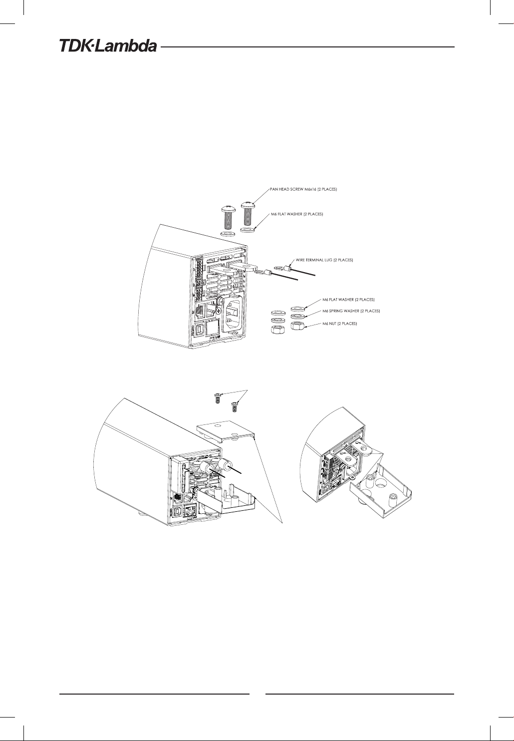
CAUTION:
Ensure that the load wiring mounting hardware does not short the output terminals. Heavy connecting
cables must have some form of strain relief to prevent loosening the connections or bending the
bus-bars.
10V to 100V Models
Refer to Fig.3-4 for connection of the load wires to the power supply bus-bars and to Fig.3-5 for
mounting the bus-bars shield to the chassis.
Fig. 3-4: Load wires connection, 10V to 100V models.
PT SCREW KA40x8 WN1412
(2 PLACES)
INSERT THE SNAP HOOKS INTO
THE DEDICATED HOLES IN THE BUS BARS.
BUS BARS PROTECTION
(PROVIDED IN THE PACKAGE)
Fig. 3-5: Bus-bars shield mounting
60V, 100V Models
WARNING:
There is a potential shock hazard when using a power supply with an output voltage greater than
60VDC. Do not turn ON power supply when output voltage is above 60VDC without output bus-bars
and output connectors protection assembled.
Ensure that the protection of output bus-bars and output connectors is mounted and properly assembled,
and that the bus bar protection is locked by two PT type screws as described in Fig. 3.5
42
Page 43
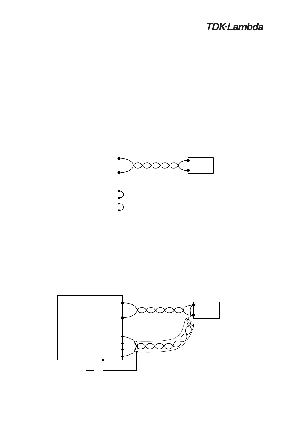
WARNUNG:
Bei Einsatz einer Stromversorgung von über 60VDC Nennspannung besteht eine potentielle
Gesundheitsgefahr durch elektrischen Schlag. Schalten Sie keine Stromversorgung mit
einer Ausgangsspannung von über 60VDC EIN, ohne dass die Schutzabdeckungen der
Ausgangsstecker oder Ausgangs-Stromschienen montiert sind. Stellen Sie sicher, dass die
Schutzabdeckungen des Ausgangssteckers bzw. der Ausgangs-Stromschienen fachgerecht
montiert wurden und wie in Bild 3.5. dargestellt mit 2 PT-Typ Schrauben gesichert sind.
3.9.7 Connecting Single Loads, Local Sensing (default)
Fig.3-6 shows recommended load and sensing connections for a single load. The local sense lines
shown are default connections at the rear panel J2 sense connector. Local sensing is suitable for
applications where load regulation is less critical.
Load lines, twisted pair, shortest length possible.
Power
Supply
+V
-V
-Rem. sense
-Local sense
+Local sense
+Rem. sense
Fig.3-6: Single load connection, local sensing
+
Load
-
3.9.8 Connecting Single Loads, Remote Sensing
Fig.3-7 shows recommended remote sensing connection for single loads. Remote sensing is
used when, in Constant Voltage mode, the load regulation is important at the load terminals. Use
twisted or shielded wires to minimize noise pick-up. If shielded wires are used, the shield should
be connected to the ground at one point, either at the power supply chassis or the load ground.
The optimal point for the shield ground should be determined by experimentation.
Load lines. Twisted pair shortest length possible.
Power
Supply
+V
-V
-Rem. sense
-Local sense
+Local sense
+Rem. sense
+
Load
-
Sense lines.
Twisted pair or shielded.
Fig.3-7: Remote sensing, single load
43
Page 44
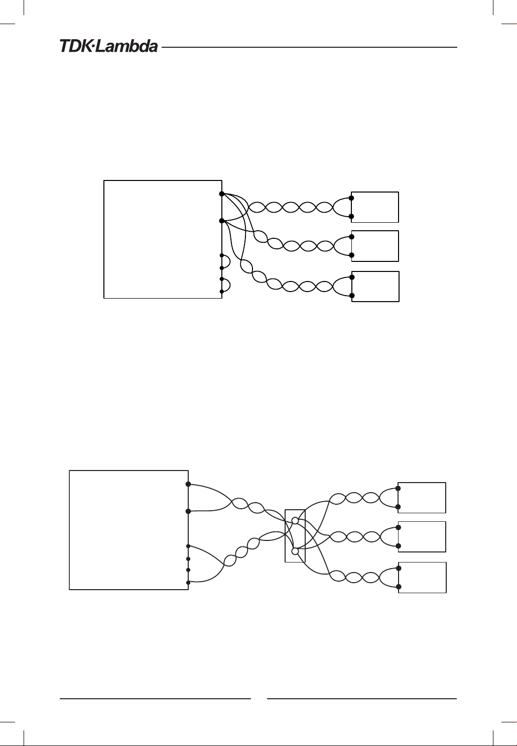
-
3.9.9 Connecting Multiple Loads, Radial Distribution Method
Fig.3-8 shows multiple loads connected to one supply. Each load should be connected to the
power supply’s output terminals using separate pairs of wires. It is recommended that each pair of
wires will be as short as possible and twisted or shielded to minimize noise pick-up and radiation.
The sense wires should be connected to the power supply output terminals or to the load with
the most critical load regulation requirement.
Load lines, twisted pair, shortest length possible.
Power
Supply
+V
-V
+
Load#1
-
+
Load#2
-Rem. sense
-Local sense
+Local sense
+Rem. sense
Fig.3-8: Multiple loads connection, radial distribution, local sense
-
+
Load#3
-
3.9.10 Multiple Load Connection with Distribution Terminals
If remotely located output distribution terminals are used, the power supply output terminals
should be connected to the distribution terminals by a pair of twisted and/or shielded wires. Each
load should be separately connected to the remote distribution terminals (see Fig.3-9).
If remote sensing is required, the sensing wires should be connected to the distribution terminals
or at the most critical load.
Distribution terminal
Power
Supply
+V
+V
-V
+
Load#1
-
+
Load#2
-Rem. sense
-Local sense
+Local sense
+Rem. sense
-V
-
+
Load#3
Fig.3-9: Multiple loads connection with distribution terminal
44
Page 45

3.9.11 Grounding Outputs
Either the positive or negative output terminals can be grounded. To avoid noise problems caused
by common-mode current flowing from the load to ground, it is recommended to ground the
output terminal as close as possible to the power supply chassis ground.
Always use two wires to connect the load to the power supply regardless of how the system is
grounded.
WARNING:
The power supllies shall not float outputs more than +/- 100VDC above/below chassis ground.
WARNUNG:
Die Ausgänge der Netzgeräte dürfen nicht mit einen Potentialunterschied zur Gehäuse - Erdung von
mehr als +/- 100VDC betrieben werden.
3.10 Local and Remote Sensing
The rear panel J2 sense connector is used to configure the power supply for local or remote sensing
of the output voltage. Refer to Fig.3-10 for sense connector location.
3.10.1 Sense Wiring
WARNING:
There is a potential shock hazard at the sense connector when using a power supply with an output
voltage greater than 60VDC. Local sense and remote sense wires should have a minimum insulation
rating equivalent or greater than the maximum output voltage of the power supply. Ensure that the
connections at the load end are shielded to prevent accidental contact with hazardous voltages.
WARNUNG:
Bei Stromversorgungen mit einer Ausgangsspannung von über 60VDC besteht an den Sense-Anschlüssen
die Gefahr eines elektrischen Schlags. Die Senseleitungen sollten mit einer Isolationsspannung
klassifiziert sein, die höher als die maximale Ausgangsspannung der Stromversorgung ist. Stellen Sie
sicher, dass die Anschlüsse an der Last abgedeckt sind, um versehentlichen Kontakt mit gefährlichen
Spannungen zu verhindern.
45
Page 46
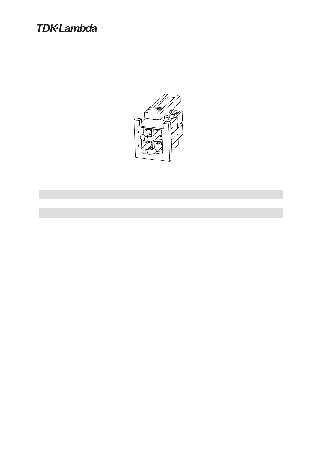
3.10.2 Local Sensing
The power supply is shipped with the rear panel J2 sense connector wired for local sensing of
the output voltage. Refer to Table 3-4 for J2 terminals assignment. With local sensing, the output
voltage regulation is made at the output terminals. This method does not compensate for voltage
drop on the load wires, therefore it is recommended only for low load current applications or
where the load regulation is less critical.
Fig.3-10: Sense connector location
Terminal Function
J2-1 Local negative sense. Connected internally to the negative output terminal (-LS).
J2-2 Remote negative sense (-S).
J2-3 Remote positive sense (+S).
J2-4 Local positive sense. Connected internally to the positive output terminal (+LS).
Table 3-4: J2 terminals
3.10.3 Remote Sensing
WARNING:
There is a potential shock hazard at the sense point when using power supply with an output voltage
greater than 60VDC. Ensure that the connections at the load end are shielded to prevent accidental
contact with hazardous voltages.
WARNUNG:
Bei Einsatz einer Stromversorgung mit einer Ausgangsspannung von über 60VDC besteht am lastseitigen
Sense-Punkt die potentielle Gefahr eines elektrischen Schlags. Stellen Sie sicher, dass die Anschlüsse
an der Last abgedeckt sind, um versehentlichen Kontakt mit gefährlicher Spannung zu vermeiden.
WARNING:
Do not operate the Power Supply with remote sense wire connected to the load without connecting
load wire to the output terminal. Make sure that the connection is reliable to avoid disconnection
during operation. Disconection may cause damage to the power supply.
WARNUNG:
Betreiben Sie die Stromversorgung niemals mit zur Last angeschlossenen Senseleitungen, wenn
nicht gleichzeitig auch die Lastleitungen angeschlossen sind. Stellen Sie sicher, dass die Leitungen
fest verbunden sind, um eine Unterbrechung im Betrieb zu verhindern. Eine Unterbrechung kann
zu Schäden an der Stromversorgung führen.
46
Page 47

CAUTION:
When using shielded sense wires, ground the shield in one place only. The location can be the power
supply chassis or one of the output terminals.
Use remote sense where the load regulation at the load end is critical. In remote sense, the power
supply will compensate for voltage drop on the load wires. Refer to the specifications for the
maximum voltage drop on load wires. The voltage drop is subtracted from the total voltage available
at the output. Follow the instructions below to configure the power supply for remote sensing:
1. Ensure that the AC On/Off is in the Off position.
2. Remove the local sense jumpers from J2.
3. Connect the negative sense lead to terminal J2-2 (-S) and the positive sense lead to terminal
J2-3(+S) of the J2 mating connector. Ensure that the J2 mating connector is plugged securely
into the rear panel sense connector, J2.
4. Turn On the power supply.
NOTES:
1. If the power supply is operating in remote sense and either the positive or negative load wire
is not connected, an internal protection circuit will activate and shut down the power supply.
To resume operation, turn the AC On/Off to the Off position, connect the open load wire, and
turn On the power supply.
2. If the power supply is operated without the remote sense lines or local sense jumpers, it will
continue to work, but the output voltage regulation will be degraded. Also, the OVP circuit
may activate and shut down the power supply.
3.10.4 J2 Sense Connector Technical Information
- J2 connector type: IPL1-102-01-S-D-RA-K, SAMTEC.
- Plug type: IPD1-02-D-K, SAMTEC.
- Contact pins: CC79R-2024-01-L, SAMTEC.
- Hand tool: CAT-HT-179-2024-11, SAMTEC
- Wire AWG: 24 up to 20
3.11 Repackaging for Shipment
To ensure safe transportation of the instrument, contact the TDK-Lambda sales or service facility
near you for Return Authorization and shipping information. Please attach a tag to the power
supply describing the problem and specifying the owner, model number and serial number of
the power supply. Refer to Warranty Information for further instructions.
47
Page 48
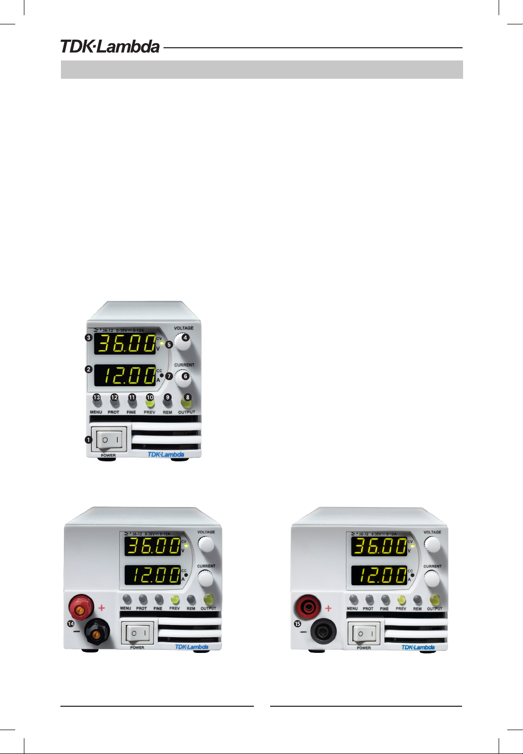
CHAPTER 4: FRONT/REAR PANEL CONTROLS AND CONNECTORS
4.1 Introduction
The Z+ Power Supply series has a full set of controls, indicators and connectors that allow the
user to set up and operate the unit. Before starting to operate the unit, please read the following
sections for an explanation of the functions, controls and connector terminals.
- Section 4.2: Front Panel Display and Controls.
- Section 4.3: Rear Panel Controls and Connectors.
4.2 Front Panel Display and Controls
Refer to Fig4-1 and Table 4-1 for description of the Front Panel controls and indicators.
Fig. 4-1: Front panel controls and indicators
48
Page 49
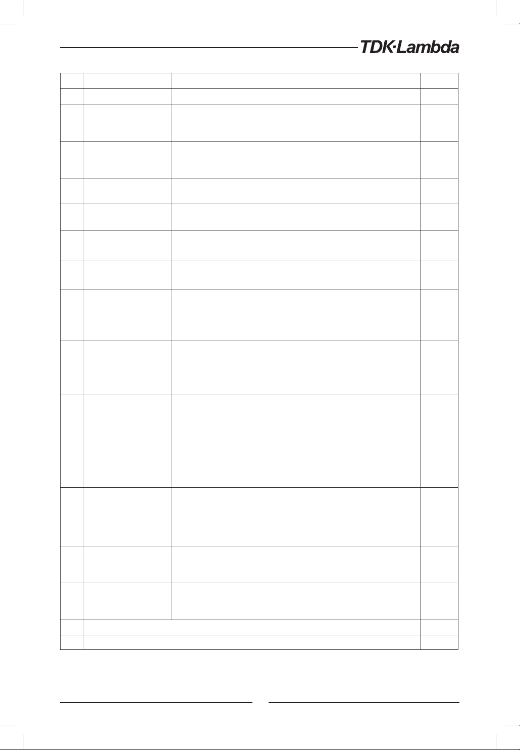
No. Control/Indicator Description Section
1 AC Power Switch AC ON/OFF control
4 digit 7-segment LED display. Normally displays the output current.
2 Current display
3 Voltage Display
Voltage encoder and
4
button
Constant Voltage mode
5
indicator
Current encoder and
6
button
Constant Current mode
7
indicator
In preview mode, the display indicates the program setting of output
current.
4 digit 7-segment LED display. Normally displays the output voltage.
In preview mode, the display indicates the program setting of output
voltage.
Encoder : high resolution rotary Encoder for adjusting the output
voltage. Button: Auxiliary function to select between menu levels.
Green LED, light for Constant-Voltage mode operation.
Encoder: High resolution rotary Encoder for adjusting the output current.
Button: Auxiliary function to select between menu levels.
Green LED, light for Constant-Current mode operation.
5.2.1
5.2.2
Main function: output ON/OFF control. Press OUTPUT to set the output
OUTPUT
8
9 REM button/indicator
10 PREV button/indicator
11 FINE button/indicator
12
13
14
15 Optional front panel insulated output sockets (Ø4mm) for modules up to 100VDC: 24A Max. PN:Z-L2
button/indicator
PROT button/
Alarm indicator
Main Menu button/
indicator
Optional front panel output jacks (binding post style, Ø4mm) for modules up to 60VDC: 24A Max. PN:Z-L
ON or OFF. Press to recovery after OVP, UVP or FOLD fails. Green LED,
lights when the DC Output is enabled.
Auxiliary function: Select between Safe Start and Auto Start modes.
Main function: Go to local. Press REM to put the unit into local (REM
button is disabled at Local Lockout mode. Green LED, lights when the
unit is in communication Remote mode.
Auxiliary function: Communication menu.
Main function: Press PREV to display the output voltage and current
limit setting. For 5 sec. the display will show the setting and then it will
return to show the actual output voltage and current. Green LED, lights
when PREV button is pressed.
Auxiliary function: Front Panel Lock. Press and hold PREV button to
toggle between ”Locked front panel” and ”Unlocked front panel”. The
display will cycle between F and F. Releasing the PREV button
while one of the modes is displayed, selects that mode.
Voltage, Current, Delay and Counter Fine/Coarse adjustment control.
Operates as a toggle switch. In Fine mode, the VOLTAGE and Current
encoders operate with high resolution and in Coarse mode with lower
resolution (approx. 6 turns). Green LED, lights when the unit is in Fine
mode.
Main function: Red LED blinks in cases of fault detection: OVP, UVP, OTP,
Foldback, Interlock and AC fail. Auxiliary function: Protection menu.
Green LED illuminates when the unit is in protection menu mode.
Used for selection between analog or digital mode control, rear panel
control parameters, memory management, trigger and program setting,
parallel mode settings and software version.
5.2.4
5.2.5
5.3
Table 4-1: Front panel controls and indicators
49
Page 50
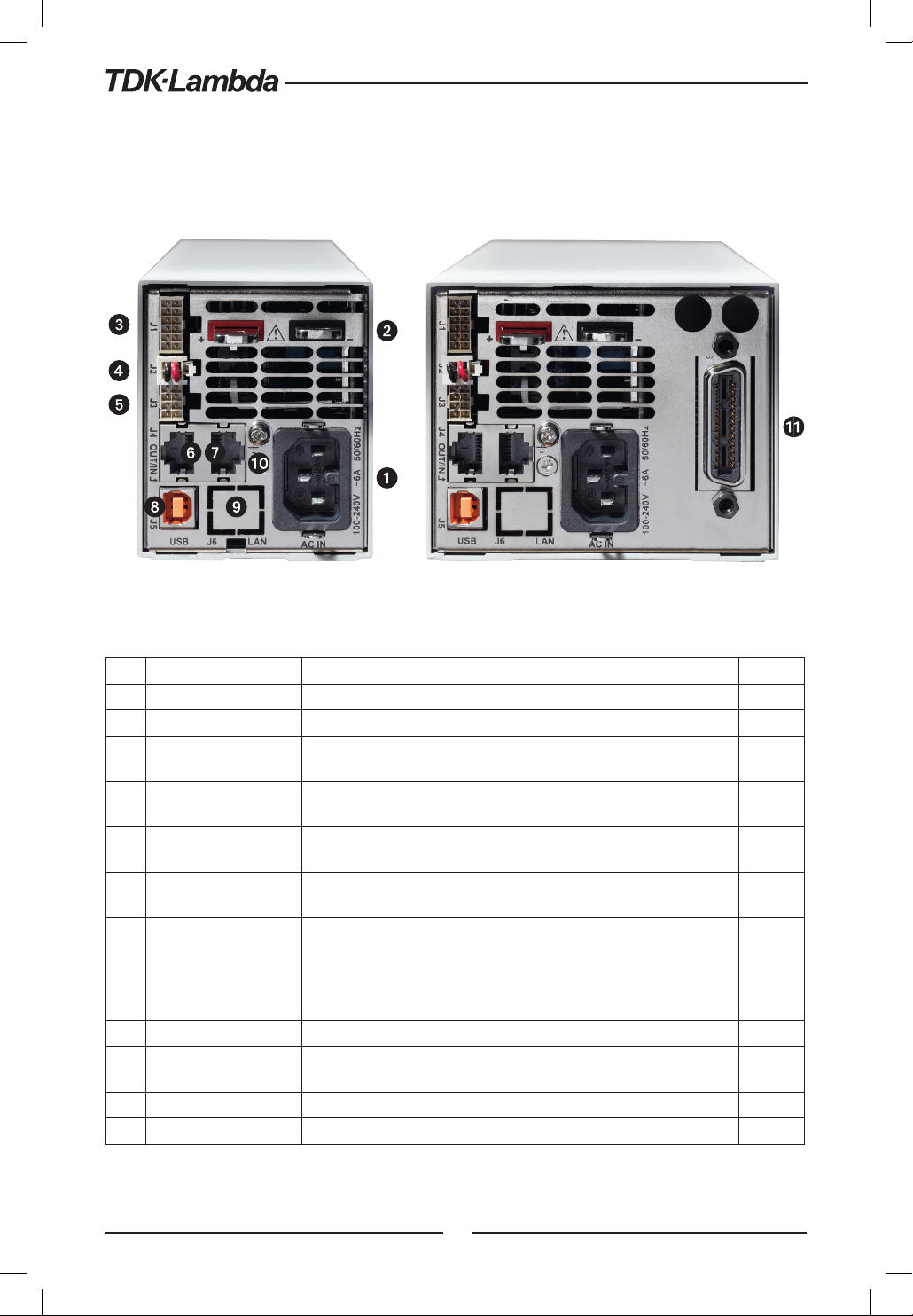
4.3 Rear Panel Connectors
Refer to Fig.4-2 and Table 4-2 for description of the Rear Panel connectors.
Fig. 4-2: Rear panel connections
No. Connection Description Section
1 AC Input Connector IEC320-16 TYPE CONNECTOR
2 DC output bus-bar Bus-bars for 10V to 100V models. Use M6 or 1/4” screws. 3.9
Analog Control and
3
signals. J1
Local/Remote sense
4
connector J2
Isolated control and
5
signal. J3
Remote Serial Out
6
connector
Remote Serial In
7
connector
8 USB Connector USB interface connector, type B
LAN Connector
9
(optional)
10 Ground screw M4X8 for chassis Ground connection
11 Optional Interface Position for GPIB Interface (shown) or Isolated Analog Interface.
Connector for remote analog interface. Analog control and monitoring.
Referenced internally to output potential -S.
Connector for making remote sensing connections to the load for
regulation of the load voltage and compensation of load wire drop.
Control and monitoring signal, isolated from the output potential. 4.3.2
RJ-45 type connector, used for chaining power supplies to/from a serial
communication bus.
RJ-45 type connector, use for connecting power supplies to RS232 or
RS485 port of computer for remote control purposes. When using several
power supplies in a power system, the first unit Remote-In is connected
to the computer and the remaining units are chained, Remote-In to
Remote-Out.
LAN interface connector, type RJ-45
4.3.1
3.10
7.3
7.3
Table 4-2: Rear panels connections
50
Page 51

WARNING:
Terminals 7, 9 and 12 of J1 are connected internally to the negative sense(-S) potential of the power
supply. Do not attempt to bias any of these terminals relative to the negative sense. Use the Isolated
Programming interface option to allow control from a programming source at a different potential
relative to the power supply negative.
WARNUNG:
Die Kontakte 7, 9 und 12 am J1 liegen intern auf dem negativ Sense (-S) Potential der Stromversorgung.
Versuchen Sie nicht, einen dieser Kontakte mit einer Spannung bezogen auf negativ Sense zu
nutzen. Verwenden Sie die optionale galvanisch getrennte Programmierschnittstelle um die
Stromversorgung mit einer Signalquelle mit abweichendem Bezugspotential gegenüber minus
Ausgang der Stromversorgung zu steuern.
CAUTION:
To prevent ground loops and to maintain the isolation of the power supply when programming from
J1, use an ungrounded programming source.
WARNING:
There is a potential shock hazard at the output when using a power supply with output greater
than 60VDC. Use wires with minimum insulation rating equivalent to the maximum output voltage
of the power supply.
WARNUNG:
Bei Einsatz einer Stromversorgung mit einer Ausgangsspannung von über 60VDC besteht die Gefahr
eines elektrischen Schlags. Verwenden Sie nur Leitungen mit Isolationsklassen, die mindestens für
die maximale Ausgangsspannung der Stromversorgung geeignet sind.
51
Page 52
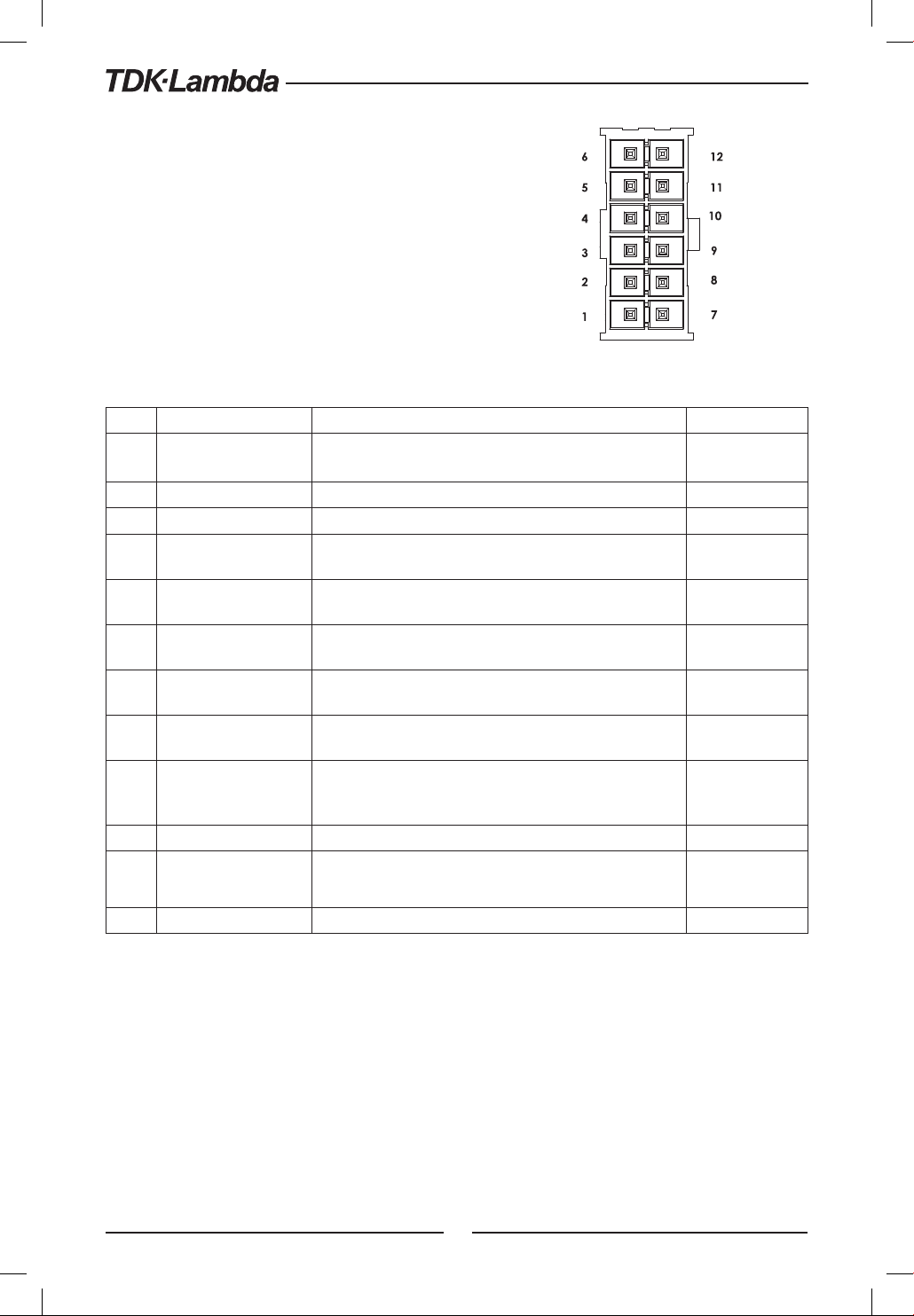
4.3.1 J1 Connector Terminal and Function
Control and monitoring signals are referenced to the
negative sense potential (-S).
Connector Technical Information:
• Connector type: IPL1-106-01-S-D-RA-K, SAMTEC
• Receptacle type: IPD1-06-D-K, SAMTEC
• Contact pins: CC79R-2024-01-L, SAMTEC
• Hand tool: CAT-HT-179-2024-11, SAMTEC
• Wire: AWG 20-24
Fig.4-3: J1 connector terminals and functions
Pin Parameter Specification Section
1 LOC/REM SELECT
2 P Output for current balance in parallel operation 5.5
3 I_MON Monitoring power supply output current 6.6
4 LOC/REM MON
5 IPGM
6 VPGM
7 COM
8 CV/CC
9 COM
Input for selecting between Local or Remote analog
programming of output voltage and output current.
Output for indicating if the unit is in Local or Remote analog
programming mode.
Input for remote analog voltage/resistance programming of
the Output Current.
Input for remote analog voltage/resistance programming of
the Output Voltage.
Control Common. Return for VMON, IMON, CV/CC, LOC/REM.
Connected internally to the negative sense potential (-S).
Output for Constant-Voltage / Constant-Current mode
indication.
Control Common. Return for VMON, IMON, CV/CC, LOC/REM.
Connected internally to the negative sense potential (-S).
6.2
6.4, 6.5
6.4, 6.5
5.8.1
10 V_MON Output for monitoring the power supply Output Voltage. 6.6
11 IPGM_RTN Return for IPGM input.
12 VPGM_RTN Return for VPGM input. Connected internally to the ” -S”.
Table 4-3: J1 connector terminals and functions
52
Page 53
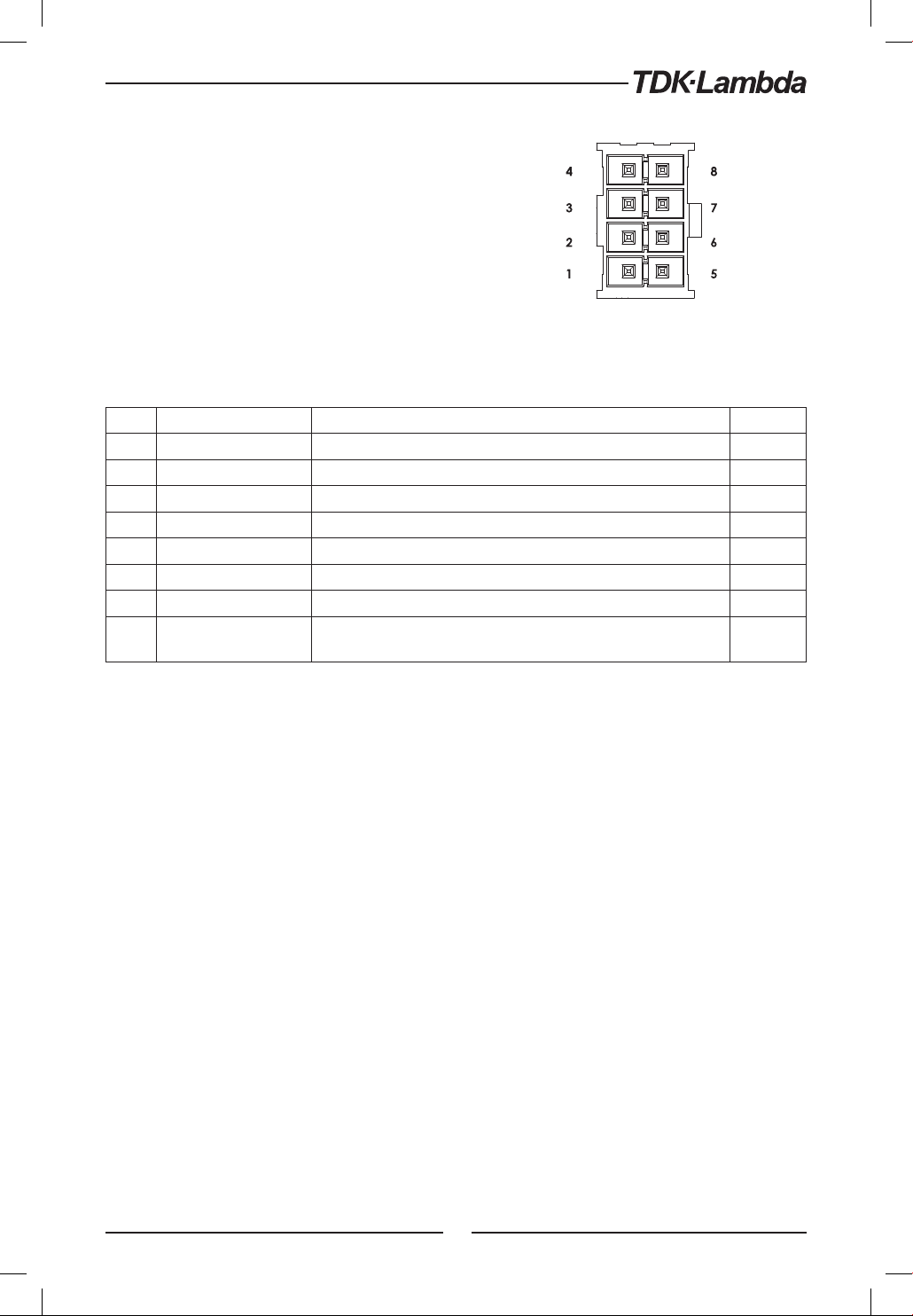
4.3.2 J3 Connector Terminal and Function
Control and monitoring signals are isolated from the
power supply output.
Connector Technical Information
• Connector type: IPL1-104-01-S-D-RA-K, SAMTEC
• Receptacle type: IPD1-04-D-K, SAMTEC
• Contact pins: CC79R-2024-01-L, SAMTEC
• Hand tool: CAT-HT-179-2024-11, SAMTEC
• Wire: AWG 20-24
Pin Signal name Function Section
1 Programmed Signal 1 General Purpose Open collector Port 1 5.7.3
2 PS_OK Output for indication of the power supply status. High level is OK. 5.7.4
3 Trigger Out Trigger output, positive true, pulse width: Min. 10usec 8.5.2
4 ILC Enable /Disable the power supply output by dry-contact (short/open). 5.7.2
5 Shut Off (SO) Input for shut off control of the power supply output. 5.7.1
6 Programmed Signal 2 General Purpose Open collector Port 2 5.7.3
7 IFC_COM Isolated interface, common.
8 Trigger In CMOS level input for triggering power supply output. Positive edge,
pulse width: Min. 10usec.
Fig.4-4: J3 connector terminals and functions
8.5.1
Table 4-4: J3 connector terminals and functions
53
Page 54
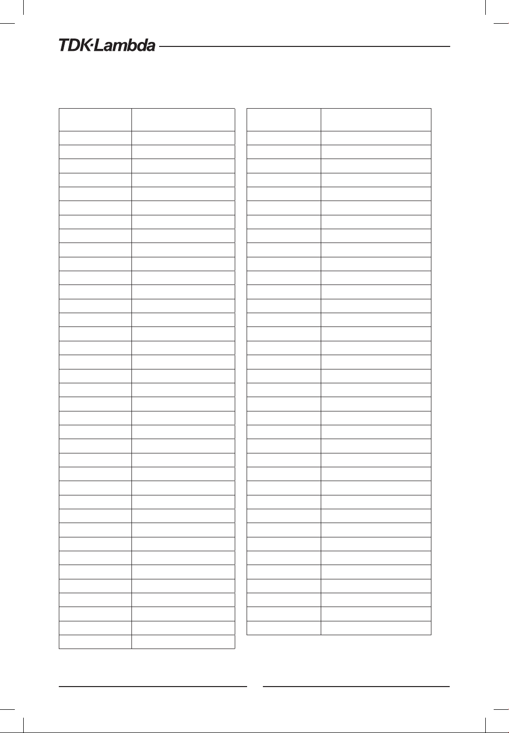
4.4 Front Panel Display Messages
Table 4-5 shows the various messages that will be shown on the display in different operating modes.
Display Text Text Description Display Text Text Description
Abor
AC
Adr
ATO
bAD
BS
Cont
CON
CvRR
CC
C
diS
EnA
.
RES
E
Err
.
O
e
ext
.
rSt
F
FA I
FOD
.
AN
F
.
STR
F
GEN
HOD
HOST
inFo
iniT
IN T F
C
I
I
An
ANG
OAD
NEG
MAC
MEMO
OFF
ABORT
AC
ADDRESS
AUTO (RESTART)
BAUD RATE
BUS
CONTINUE
COUNTER
CURRENT
CC
CV
DISABLE
ENABLE
EXT.RESISTOR
ERROR
EXT.VOLTAGE
EXTERNAL
FACTORY RESET
FAIL
FOLDBACK
FRONT PANEL
FUNCTION STROBE
GEN LANGUAGE
HOLD
HOST
INFORMATION
INITIALIZE
INTERFACE
INTERLOCK
IP
LAN
LANGUAGE
LOAD
NEGATIVE
MAC
MEMORY
OFF
ON
ONCE
OT
O
R
in1
in2
OS
ROG
.
D
R
sd
RANG
.
AN
R
REC
RST
rev
232
45
SAFE
SAE
SCI
SO
SET
SE
SAD
S
STE
TRiG
TR.D
.
TR
.
Ov
TR
SB
OT
YES
ON
ONCE
OTP
OVP
PARALLEL
PIN 1
PIN 2
POSITIVE
PROGRAM
PROTECTION DELAY
PS_OK DELAY
RANGE
REAL PANEL
RECALL
RESET
.
In
REVISION
RS232
RS485
SAFE (START)
SAVE
SCPI
SHUT OFF
SET
SLAVE
SLAVE (ADVANCED)
SLAVE (BASIC)
STEP
TRIGGER
TRIGGER DELAY
TRIGGER IN
TRIGGER OUT
USB
UVL
UVP
VOLTAGE
YES
Table 4-5: Front Panel display messages
54
Page 55
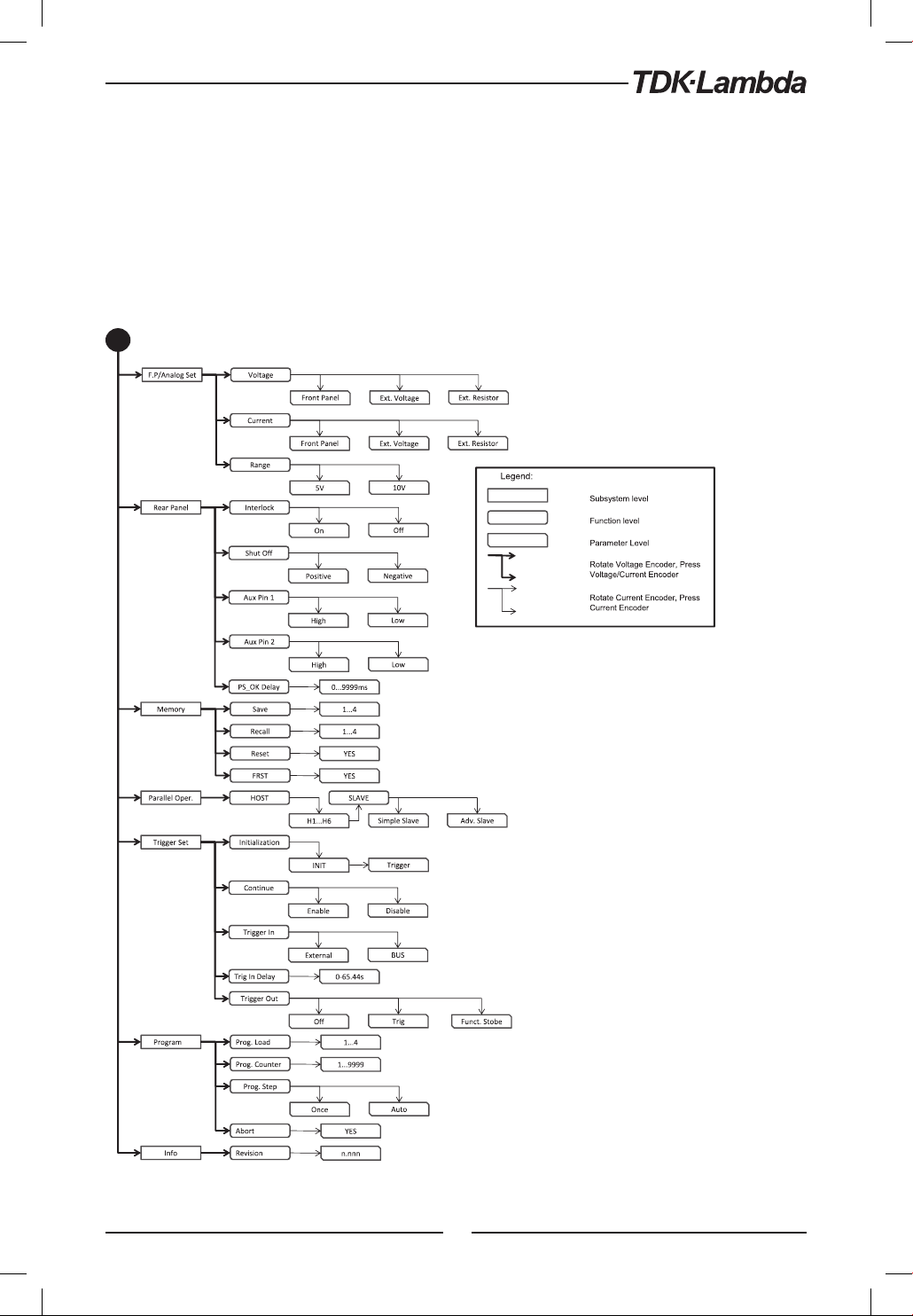
4.5 Navigating the Main Menu
4.5.1 Introduction
The Main Menu consists of three levels: Subsystem, Function and Parameter. To enter the Menu
press the Menu button. The Menu LED illuminates and the display shows the Subsystem Menu.
Navigate by rotating the Voltage encoder to scroll through the Subsystem list (first level). Repeat
these actions to navigate the Functions list (second level). In the third level, the Voltage display
shows the function and the Current display shows the parameter. Scroll the parameter list by
rotating the Current encoder and press to select the desired parameter. When parameter is
accepted, the display blinks once and exits to the previous level.
Press MENU button, LED turns ON
Fig.4-5: Main Menu diagram
55
Page 56

4.5.2 Exiting the Main Menu
There are three ways to exit from Main Menu:
1. Press MENU button twice. MENU LED turns OFF. Display shows present status of power supply.
2. Press and hold MENU button 3sec. MENU LED turns OFF. Display shows present status
of power supply.
3. No action for 15 sec. MENU LED turns OFF. Display shows present status of power supply.
4.6 Navigating Communication Menu
4.6.1 Introduction
The Communication Menu consists of two /three levels: Function level and Parameter level.
To navigate the Communication Menu press REM button. The REM LED illuminates. The function
menu item appears on the display. Navigate by rotating the Voltage encoder to scroll the function
level. To select the desired function, press the Encoder button next to the display. In the Parameter
level, the Voltage display shows the function and the Current display shows the parameter. Scroll
the parameter list by rotating the Current encoder and press to select the desired parameter.
When parameter is accepted, the display blinks once and exits to the previous level.
Press REM button, LED turns ON
Fig.4-6: Communication Menu diagram
56
Page 57
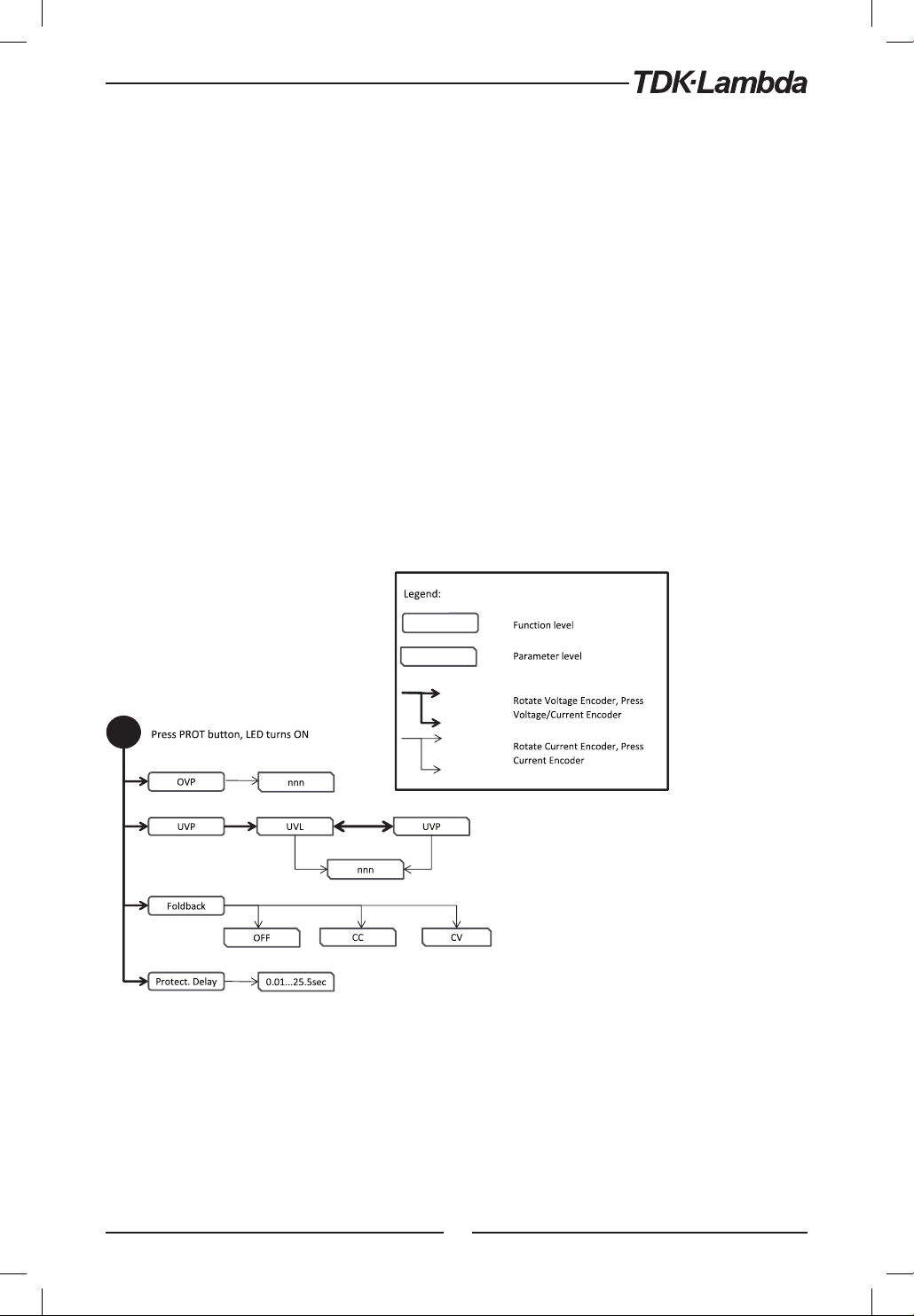
4.6.2 Exiting the Communication Menu
There are three ways to exit from REM menu:
1. Press REM button twice. REM LED turns OFF. Display shows present status of power supply.
Press and hold REM button 3sec. REM LED turns OFF. Display shows present status of power supply.
2.
3.
No action for 15 sec. REM LED turns OFF. Display shows present status of power supply.
4.7 Navigating the Protection Menu
4.7.1 Introduction
The Protection Menu consists of two levels: Function and Parameter.
To navigate the Protection Menu press PROT button. The PROT GREEN LED illuminates. The
function menu item appears on the display. Navigate by rotating the Voltage encoder to scroll
the function level. To select the desired function, press the Encoder button next to the display.
Toggle the Voltage encoder to select either UVL or UVP functions.
In the Parameter level, the Voltage display shows the function and the Current display shows the
parameter. Scroll the parameter list by rotating the Current encoder. Selection of a numerical
parameter is automatic and the Encoder cannot be pressed. Press only to select Foldback parameter.
When parameter is accepted the display blinks once and exits to the previous level.
Fig.4-7: Protection Menu Navigation
4.7.2 Exiting the Protection Menu
There are three ways exit the menu:
1. Press PROT button twice. PROT LED turns OFF. Display shows present status of power supply.
Press and hold PROT button 3sec. PROT LED turns OFF. Display shows present status of power supply.
2.
3.
No action for 15 sec. PROT LED turns OFF. Display shows present status of power supply.
57
Page 58

CHAPTER 5: LOCAL OPERATION
5.1 Introduction
This Chapter describes the operating modes that do not require programming and monitoring the
power supply via its communication interface. USB or RS232/RS485 or by remote analog signals.
Ensure that the REM LED on the front panel is Off, (indicating Local mode). If the REM LED is On,
press the front panel REM button to change the operating mode to local.
- For information regarding remote analog programming refer to Chapter 6.
- For information regarding usage of the serial communication port refer to Chapter 7.
5.2 Standard Operation
The power supply has two basic operating modes: Constant Voltage mode and Constant Current
mode. The mode in which the power supply operates at any given time depends on the output
voltage setting, output current limit setting and the load resistance.
5.2.1 Constant Voltage Mode and Voltage Setting
1. In constant voltage mode, the power supply regulates the output voltage at the selected
value, while the load current varies as required by the load.
2. While the power supply operates in constant voltage mode, the CV LED on the front panel
illuminates.
3. Adjustment of the output voltage can be made when the power supply output is enabled
(Output On) or disabled (Output Off). When the output is enabled, simply rotate the Voltage
encoder knob to program the output voltage. When the output is disabled, press the PREV
button and then rotate the Voltage encoder to required value. The Voltage display will show
the programmed output voltage for 5 seconds. Then ”OFF” will appear on the Vol tage d ispl ay.
4. Resolution can be set to Coarse or Fine adjustment. Press FINE button to select between the
lower and higher resolution. The FINE LED illuminates when the resolution is set to Fine.
NOTE:
If after completing the adjustment, the display shows a different value than the setting, the power
supply may be at current limit. Check the load condition and the power supply current limit setting.
NOTE:
The maximum and minimum setting values of the output voltage are limited by the Over Voltage
protection and Under Voltage limit setting. Refer to sections 5.3.2 and 5.3.3 for more details.
5.2.2 Constant Current Mode and Current Setting
1. In constant current mode, the power supply regulates the output current at the selected value, while
the voltage varies with the load requirement.
2. While the power supply is operating in Constant Current mode, the CC LED illuminates.
3. Adjustment of the output current can be made when the power supply output is enabled
(Output On) or disabled (Output Off). When the output is enabled, simply rotate the Current
encoder knob to program the output current. When the output is disabled, press the PREV
button and then rotate the Current encoder to required value. The Current display will show
the programmed output current for 5 seconds. Then ”OFF” will appear on the Vol tage displ ay.
4. Resolution can be set to Coarse or Fine adjustment. Press the FINE button to select between the
Coarse and Fine adjustment. The FINE LED illuminates when the resolution is set to Fine.
58
Page 59

5.2.3 Automatic Crossover
When the power supply operates in Constant Voltage mode, while the load current is increased
to greater than the current limit setting, the power supply will automatically switch to Constant
Current mode. If the load is decreased to less than the current limit setting, the power supply will
automatically switch back to Constant Voltage mode.
5.2.4 Output On/Off Control
The Output On/Off enables or disables the power supply output. The Output On/Off can be
activated from the front panel using the OUTPUT button or from the communication interface.
The OUTPUT button can be pressed at any time (except in Front Panel Lock mode or when a Fault
condition exists). When the output is disabled, the output voltage and current fall to zero and the
Voltage display shows ”OFF”. Press the OUTPUT button to recover from Faults such as: OVP, UVP
and FOLD faults, after the Fault conditions have been removed.
5.2.5 Safe Start and Auto-Restart Modes
At turn on, the power supply AC On/Off can start at last setting of Output Voltage and Current
limit with the output enabled (Auto-restart), or it can start with the output disabled (Safe mode).
Press and hold the OUTPUT button to toggle between Safe start and Auto-restart modes. The
Voltage display will continuously cycle between ”SAFE” and ”ATO” every 3 seconds. Releasing
OUTPUT button while one of the modes is displayed, selects that mode. The default setting at
shipment is in Safe mode.
• Automatic Start Mode (ATO)
The power supply is restored to last operation setting. Upon start-up, the output is enabled
or disabled according to the last setting.
• Safe Start Mode (SA FE)
The power supply is restored to last operation setting and sets the Output to Off state. At
start-up, the output is disabled and the output voltage and current are zero. To enable the
output, momentarily press OUTPUT button.
5.2.6 Viewing Software Revision
Via the Front Panel Menu, it is possible view installed software revision.
1. Press MENU button. MENU (GREEN) LED illuminates. ”set” message appears on the Voltage
display.
2. Rotate Voltage encoder until ”i n o” message appears on Voltage Display.
.
3. Press Voltage encoder. The ”Rev
revision number appears on the Current display.
” message appears on the display, and the installed software
59
Page 60

5.3 Alarms and Protective Functions
5.3.1 Introduction
There are several conditions that cause alarm (RED LED blinks). All alarms affect the output. When
an alarm occurs, the respective fault will appear on the display and the alarm LED illuminates. It
is possible that more than one fault (alarm) may be triggered but only the first will be shown on
the display. If the second fault is still active when the first fault is removed, then the second fault
will be displayed.
The following protective functions are incorporated in the power supply:
• OVP - Over Voltage Protection
• UVP - Under Voltage Protection
• ILC - Interlock
• FOLD - Fold Back Constant Current or Constant Voltage
• AC FAIL - AC Power shut down
• OTP - Over Temperature Protection
5.3.2 Over Voltage Protection
The OVP circuit protects the load in the event of a remote or local programming error or a power
supply failure. The protection circuit monitors the voltage at the power supply sense points thus
providing the protection level at the load. Upon detection of an Over Voltage condition, the power
supply output will shut down.
5.3.2.1 Setting the OVP Level
The OVP can be set when the power supply output is Enabled (On) or Disabled (Off ). The minimum
setting level is 5% above the output voltage, or the value in Table 5-1, whichever is higher.
The maximum setting level is shown in Table 5-1.
1. Press PROT button. PROT (GREEN) LED illuminates. ”O” message appears on the Voltage
display.
2. Press Voltage encoder. ”O” message appears on the Voltage display and the Current display
shows OVP setting level.
3. Rotate the Current encoder to adjust the OVP level.
4. Press PROT button twice or wait 15 sec. to return display to its previous state and then PROT
LED turns OFF.
Min. OVPMax. OVPModel
0.5V12.0V10V
1.0V24.0V20V
2.0V40.0V36V
5.0V66.0V60V
5.0V110.0V100V
Table 5-1: Maximum/Minimum OVP setting levels
60
Page 61

5.3.2.2 Resetting the OVP Circuit
To reset the OVP circuit after activation:
1. Reduce the power supply Output Voltage setting below the OVP set level.
2. Ensure that the load and the sense wiring is connected properly.
3. Four methods to reset the OVP circuit.
• Press OUTPUT button.
• AC recycle.
• On/Off recycle by analog control (Interlock).
• Send communication command to enable output.
5.3.3 Under Voltage Protection and Under Voltage Limit
The UVL function prevents output voltage setting below UVL set value. The UVP function prevents
power supply operation if output voltage is below UVP set value. Upon detection of an Under
Voltage condition, the power supply output will shut down. The UVL prevents adjustment of the
output voltage below a certain limit. The combination of UVP/UVL and OVP functions, allows the
user to create a protection window for sensitive load circuitry.
5.3.3.1 Setting the UVP/UVL Mode and Level
The UVP/UVL can be set when the power supply output is Enabled (On) or Disabled (Off ). UVL
and UVP setting values are limited at the maximum level to approximately 5% below the Output
Voltage setting. Attempting to adjust the value above this limit will result in no response to the
adjustment attempt. The minimum value setting is zero. If UVP setting is below 5% of rated output
voltage, UVP will act as UVL. When UVP is selected, UVL will be disabled and Vice Versa.
1. Press PROT button. PROT (GREEN) LED illuminates. Current display shows ”” message.
2. Press Current Encoder. Voltage Display shows ”” or ”” message, Current display shows
setting level.
3. Rotate the Voltage encoder to set ”” or ””, and then press the encoder. The display
blinks once.
4. Rotate the Current encoder to adjust the level.
5. Press PROT button twice or wait 15 sec. to return display to its previous state and then PROT
LED turns OFF.
5.3.3.2 Activated UVP Alarm
When the UVP is activated the power supply output shuts down. The Voltage and Current display
shows ” FA
5.3.4 Foldback Protection
Foldback protection will shut down the power supply output if power supply operation mode
crosses over from CC to CV or from CV to CC, according to selected operation mode. There are
three states of foldback protection. OFF (default), CV, CC. For CC to CV protection mode, setting
should be CV. For CV to CC protection mode, setting should be CC.
I” and the PROT red LED blinks.
61
Page 62

5.3.4.1 Setting the Foldback Protection
The Foldback can be set when the power supply output is Enabled (On) or Disabled (Off ).
Press PROT button. PROT (GREEN) LED illuminates. The ”O” message appears on the Voltage display.
1.
2. Rotate Voltage encoder until ”FOD” message appears on Voltage display.
3. Press Voltage encoder. ”FOD” message appears on Voltage Display, and on Current display
shows ”OFF” or ”CC” or ”C ” setting mode.
4. Rotate the Current encoder to adjust required mode and press to select. Display returns to
the previous level.
5. Press PROT button to return display to its previous state (PROT LED turns OFF).
5.3.4.2 Activated FOLD Alarm
When the Foldback is activated the power supply output shuts off. The Voltage and Current display
shows ”FOD FA
5.3.5 Protection Delay
A delay can be set from between the time when a fault is detected and the output is disabled. It
relates only in cases of UVP and Foldback protection.
5.3.5.1 Setting the Protection Delay
1. Press PROT button. PROT (GREEN) LED illuminates. The ”O” message, appears on the Voltage
display.
2. Rotate Voltage encoder until ”R
Encoder.
3. The ”R.D” message appears on the Voltage Display. The Current display shows the value in
seconds.
4. Rotate the Current encoder to adjust the delay. Protection delay setting range is 0…25.5sec.
5. Press Current encoder to select. Display blinks once and exists to the previous level.
6. Press PROT button once to return display to the previous state and PROT LED turns off.
I” and the PROT red LED blinks.
NOTE:
UVP protection delay = 500ms + delay setting.
.
D” message appears on Voltage display, and then press the
5.3.6 Over Temperature Protection
The OTP circuit shuts down the power supply before the internal components can exceed their
safe internal operating temperature. When an OTP shutdown occurs, the display shows ”Ot
and the PROT LED blinks. Resetting the OTP circuit can be automatic (non-latched) or manual
(latched) depending on if he power supply is in Safe or Automatic restart mode.
• Safe start mode: The power supply stays off after the OTP condition has been removed. The
display continue to shows ”O t I” and the PROT LED continues to blink. To reset the OTP
circuit, press OUTPUT button (or send Output Enable command).
• Auto-restart mode: The power supply recovers to it’s last setting automatically after the OTP
condition is removed.
5.3.7 AC Fail Alarm
The AC Fail alarm indicates whether the AC input has been discounted or shut down. When any of
these faults occur, the display shows ”AC I”. Output power is disabled, and the PROT LED blinks.
• Safe start mode: The power supply returns to ”OFF”, after the AC power returns.
• Auto-restart mode: The power supply recovers to it’s last setting automatically when AC
power returns.
62
I”
Page 63
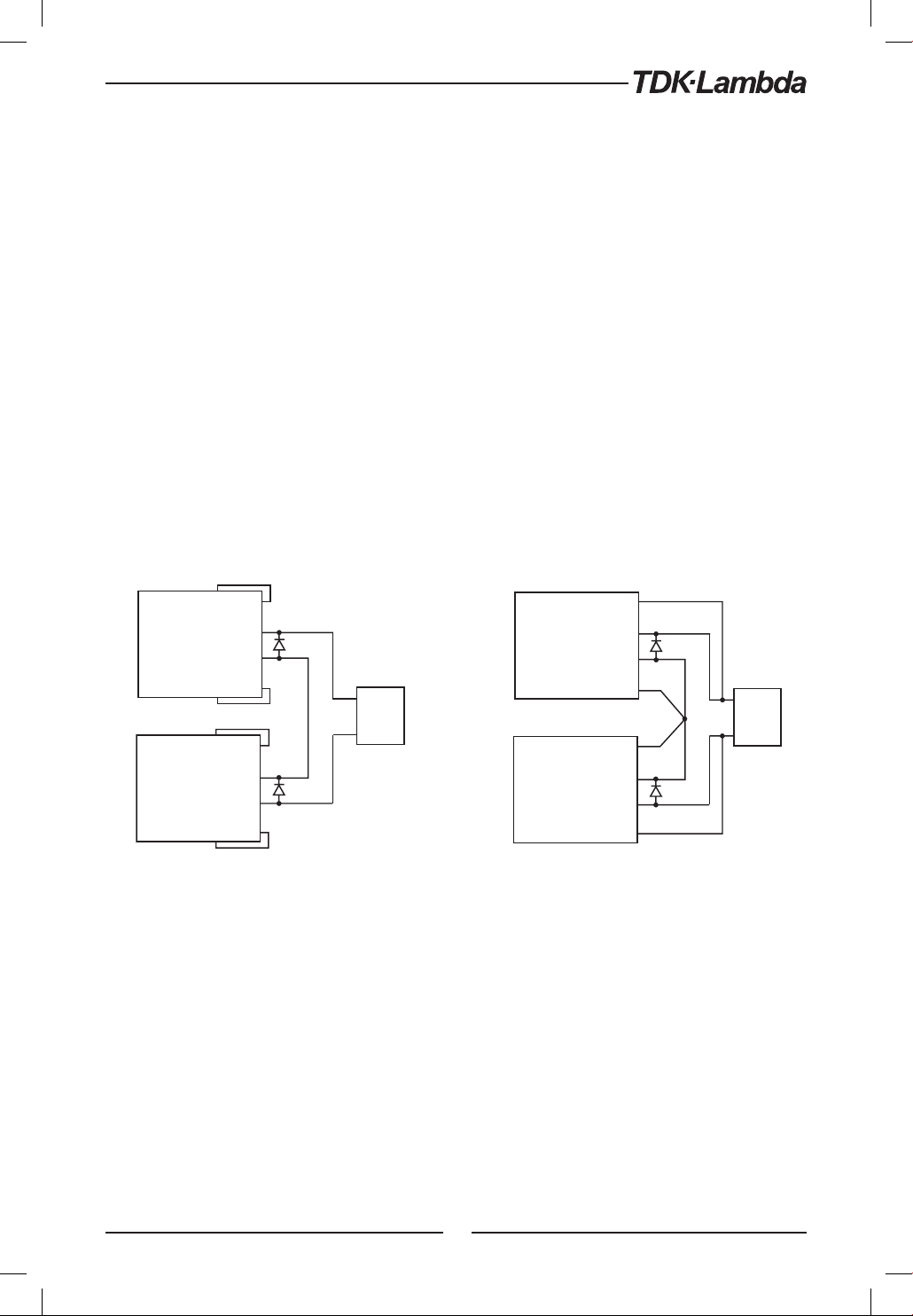
5.4 Series Operation
Power supplies of the same model can be connected in series to obtain increased output voltage.
Split connection of the power supplies gives positive and negative output voltage.
WARNING:
When power supplies are connected in series, and the load or one of the output terminals is grounded,
no point may be at a greater potential of +/- 100VDC from ground.
WARNUNG:
Bei Reihenschaltung mehrerer Geräte und Verbindung der Last bz w. eines Ausgangspoles mit SystemMasse, sollte kein Potential von über +/- 100VDC zwischen Ausgang und System-Masse anliegen.
5.4.1 Series Connection for Increased Output Voltage
Two units are connected so that their outputs are summed. Set the current limit of each power
supply to the maximum that the load can handle without damage. It is recommended that diodes
be connected in parallel with each unit output to prevent reverse voltage during start up sequence
or in case one of the units shuts down. Each diode should be rated to at least the power supply
rated output voltage and output current. Refer to Fig.5-1 and Fig.5-2 for series operation with
local and remote sensing.
+S
+LS
+LS
+S
-LS
+LS
-LS
+S
+
(*)
-
-S
+
LOAD
POWER
SUPPLY
-
+
(*)
-
-S
(*) Diodes are
user supplied.
POWER
SUPPLY
POWER
SUPPLY
POWER
SUPPLY
Fig.5-1: Series connection, local sensing Fig.5-2: Series connection, remote sensing
-LS
+LS
-LS
+S
+
(*)
-
-S
+
LOAD
-
+
(*)
-
-S
63
Page 64
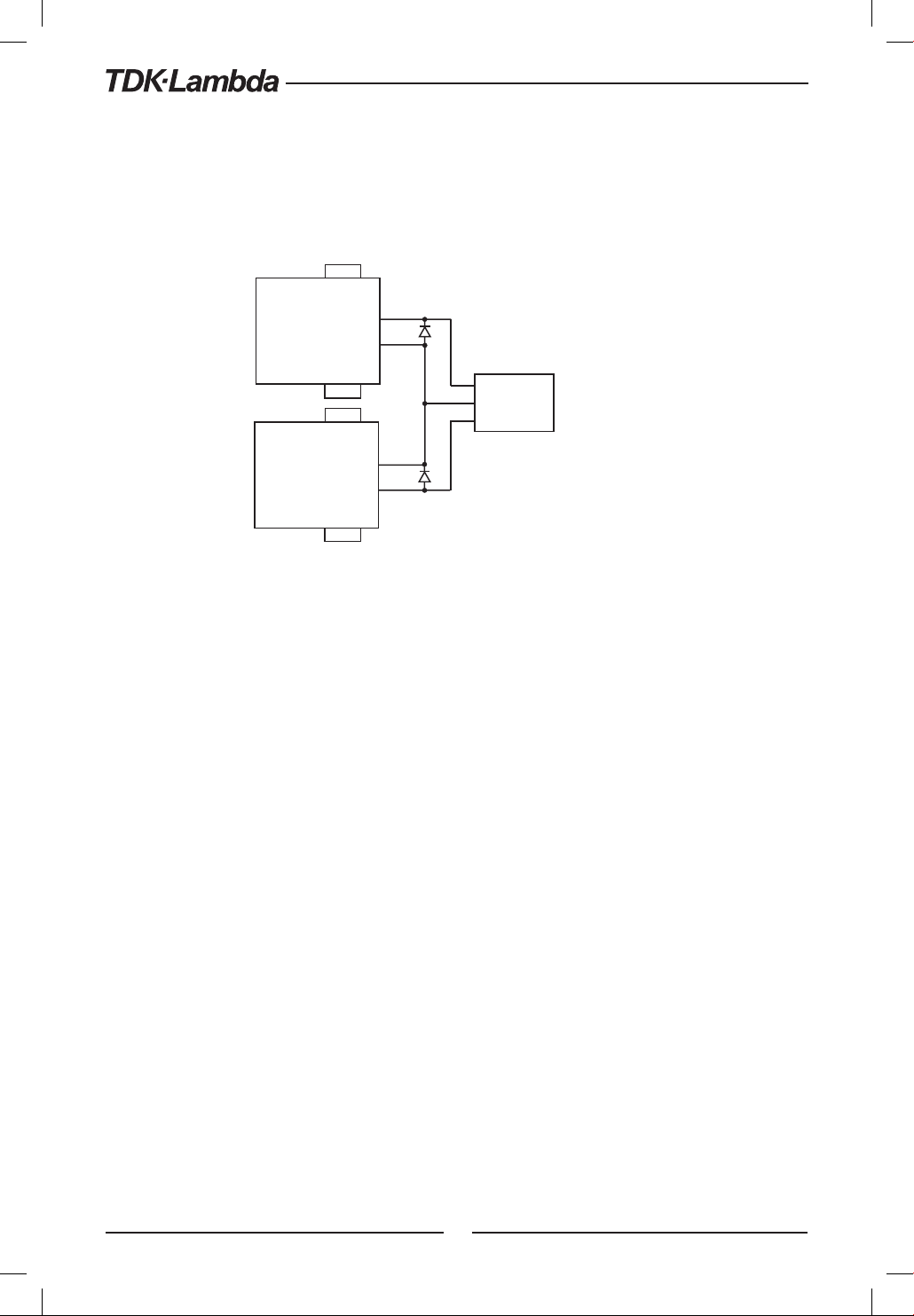
5.4.2 Series Connection for Positive and Negative Output Voltage
In this mode, two units are configured as positive and negative output. Set the current limit of each
power supply to the maximum that the load can handle without damage. It is recommended that
diodes be connected in parallel with each unit output to prevent reverse voltage during start-up
or in case one of the units shuts down. Each diode should be rated to at least the power supply
rated output voltage and output current. Refer to Fig.5-3 for this operating mode.
+S
+LS
-LS
-LS
+LS
+
-
-S
+S
+
-
-S
(*)
+
LOAD
COM.
-
(*)
(*) Diodes are user supplied.
POWER
SUPPLY
POWER
SUPPLY
Fig.5-3: Series connection for positive/negative output voltages
5.4.3 Remote Programming in Series Operation
Programming by external voltage: The analog programming circuits of this power supply are referenced
to the negative Sense potential. Therefore, the circuits used to control
each series connected unit must be separated and floated from each
other. Refer to section 6.4
Using the SO function and PS_OK signal : The Shut Off and PS_OK circuits are referenced to the isolated interface
common, IFC_COM (J3-7). The IFC_COM terminals of the units can be
connected to obtain a single control circuit for the power supplies
connected in series.
Programming by external resistor : Programming by external resistor is possible. Refer to section 6.5 for
details.
Programming via the Serial Communication
port (RS232/RS485, USB):
The Communication port is referenced to the IFC_COM which is
isolated from the power supply output potential. Therefore power
supplies connected in series can be chained using the Remote-In and
Remote-Out connectors. Refer to Chapter 7 for details.
64
Page 65
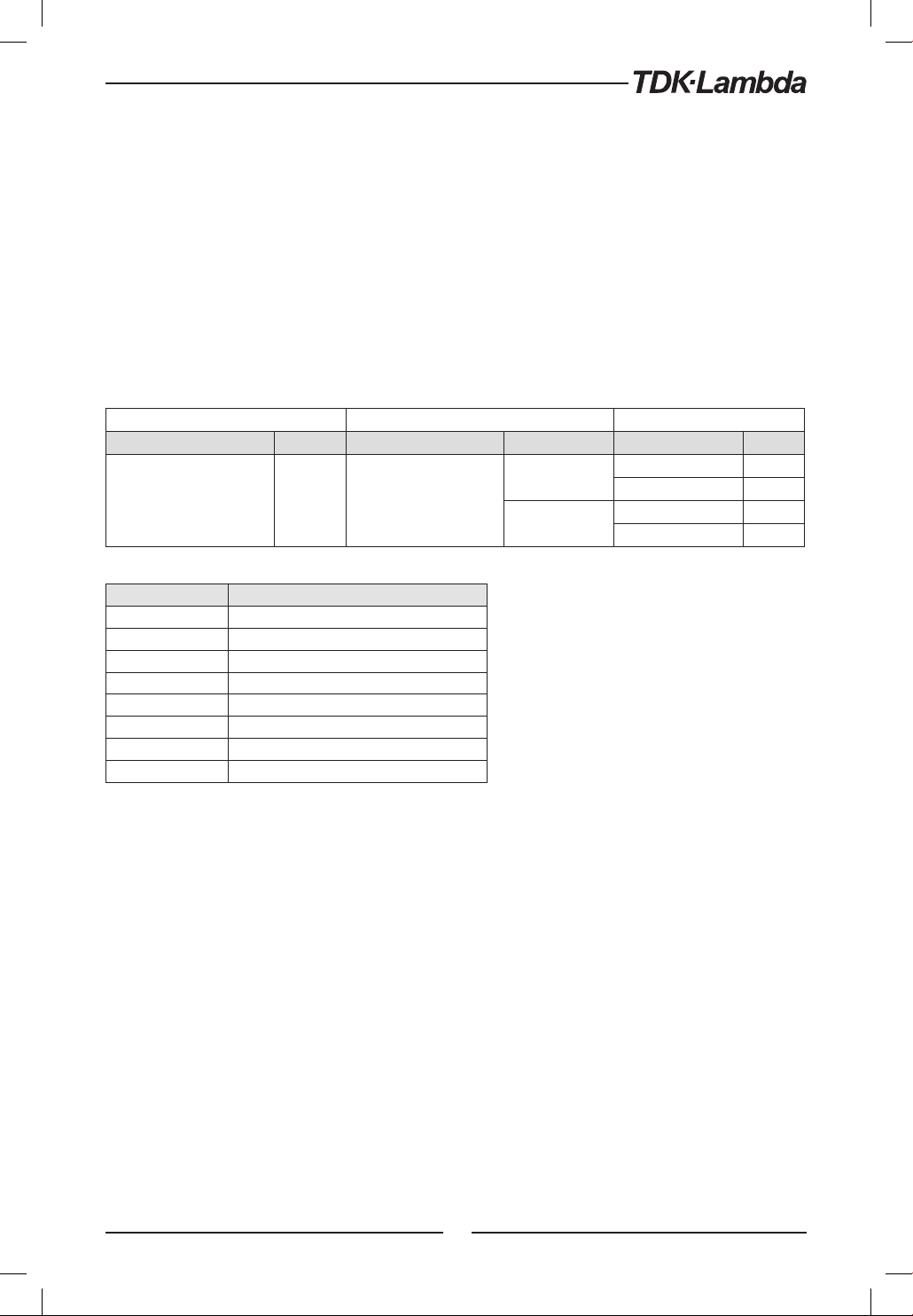
5.5 Parallel Operation
5.5.1 Introduction
Up to six units of the same Voltage and Current rating can be connected in parallel to provide up
to six times the output current capability. One of the units operates as a master and the remaining
units are slaves. The slave units are analog programmed by the master unit. In remote digital
operation, only the master unit can be programmed by the computer while the slave units may
be connected to the computer for voltage, current and status readback only.
The Master and Slave modes are stored in the power supply EEPROM when the AC power is turned
off. The system will return to the Master/Slave mode upon re-application of AC power.
There are two methods to configure multiple supplies for parallel operation (basic and advanced).
Refer to Section 5.5.2 and to Section 5.5.3 for detailed explanation. Parallel modes are selected
via Front Panel menu. Refer to table 5-2.
Subsystem Level Function Level Parameter Level
Description Display Function Display Description Display
H1
H2
S
SAD
..
H
Parallel Operating Mode
r
Table 5-2. Parallel subsystem menu
Display Operating Mode
H1
H2
H3
H4
H5
H
S
SAd
Single unit (default)
Master unit with 1 Slave unit
Master unit with 2 Slave units
Master unit with 3 Slave units
Master unit with 4 Slave units
Master unit with 5 Slave units
Slave unit (Basic mode)
Slave unit (Advanced mode)
Table 5-2.1: Operation Setting Mode
Host /Basic Slave /
Advanced Slave
HOst
Se
Single power supply
Master
Slave (Basic)
Slave (Advanced)
5.5.2 Basic Parallel Operation
In this method, setting the units as Master and Slaves is made by the rear panel J1 connections
and setup via Front Panel. Each unit displays its own output current and voltage. To program the
load current, the Master unit should be programmed to the total load current divided by the
number of units in the system. The master and slave units operate in a Daisy-Chain connection
configuration. For further details about Daisy-chain connection refer to section 5.6. Refer to the
following procedure to configure multiple supplies for basic parallel operation.
5.5.2.1 Master Unit Set Up
During operation, the master unit operates in CV mode, regulating the load voltage at the
programmed output voltage. Connect the sensing circuit to local or remote sensing as shown in
Fig.5-4 or Fig.5-5. Front Panel Main Menu Parallel mode is ”H1” as default.
1. Press MENU button.
2. Rotate Voltage encoder until ”r” appears on Voltage display, then press Voltage encoder.
3. Rotate Current encoder until ”H1 ” appears.
Press Current encoder to select ”H1 ”, the display blinks once and returns to previous menu level.
4.
5. Set the master unit output voltage to the desired voltage. Program the current limit to the
desired load current limit, divided by the number of parallel units.
6. If there is more than one Slave unit connected to the Master, then set the PS_OK signal delay
of the Master to 200msec. Refer to section 5.7.4 Power Supply OK Signal.
65
Page 66
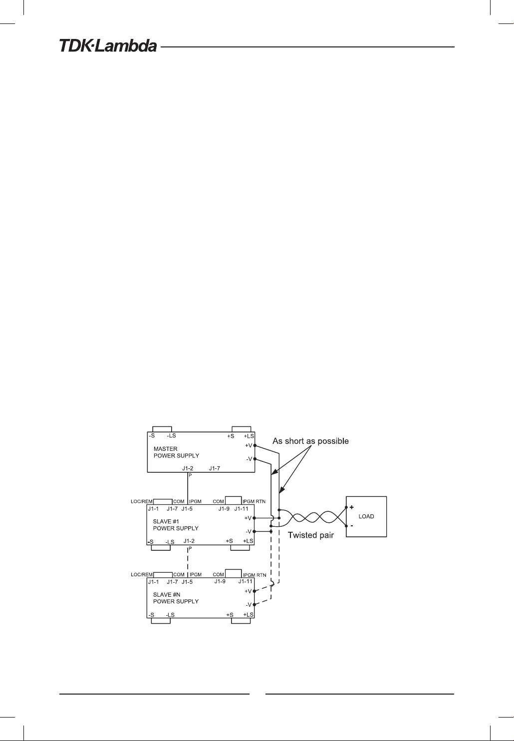
5.5.2.2 Slave Unit Set Up
When Slave mode is selected the power supply enters Current programming mode via external
Voltage. Voltage and Current programming setting values are set to 105% of range. During operation
the slave units operate as a controlled current source following the master output current. It is
recommended that the power system is designed so that each unit supplies up to 95% of its current
rating. This helps reduce imbalance which may occur by cabling and connections voltage drop.
1. Press MENU button
2. Rotate Voltage encoder until ”r” appears on Voltage display, then press Voltage encoder.
3. Rotate Current encoder until ”S” appears.
4. Press Current encoder to select ”S”. Display blinks once and returns to previous display.
5. For wiring instructions, refer to Fig.5-4: Parallel connection with local sensing or Fig.5-5:
Parallel connection with remote sensing.
5.5.2.3 Setting Over Voltage Protection
The master unit OVP should be programmed to the desired OVP level. In slave mode, the power
supply is set to maximum as default.
5.5.2.4 Setting Foldback Protection
Foldback protection, if desired, may only be used with the master unit. When the master unit shuts
down it programs the slave units to zero output voltage.
5.5.2.5 Connection to Load
In parallel operation, power supplies can be connected in local or remote sensing. Refer to Fig.5-4
and 5-5 for typical connections of parallel power supplies. The figures show connection of two
units, however the same connection method applies for up to 6 units.
Fig.5-4: Parallel connection with local sensing
66
Page 67
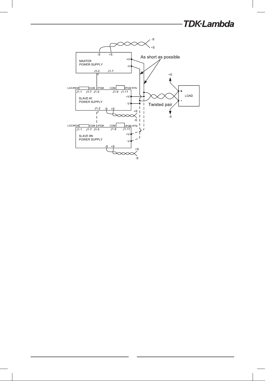
Fig.5-5: Parallel operation with remote sensing
CAUTION:
Make sure that the connection between - Vo terminals is reliable to avoid disconnection during
operation. Disconnection may cause damage to the power supply.
NOTE:
With local sensing it is important to minimize the wire length and resistance. Also the positive and
negative wire resistance should be as close as possible to each other to achieve current balance
between power supplies.
67
Page 68

5.5.3 Advanced Parallel Operation
5.6 Daisy-Chain Connection
It is possible to configure a multiple power supply system to shut down all units when a fault
condition occurs in one of the units. When the fault is removed, the system recovers according to
a preset state: Safe start mode or Automatic restart.
Set signal ”SO” to positive logic via Front panel (refer to section 5.7.1) . If a fault occurs in one of
the units it’s ”PS_OK” signal will be set to low level and the display will indicate the fault. The other
units will shut off and their displays will indicate ”SO”. When the fault condition is removed, the
units will recover to their last setting according to their respective Safe start or Auto-restart setting.
Fig.5-6 shows connection of three units, however the same connection method applies to systems
with more units.
P OWE R S U PP LY
#1
J3 -7
J3 -2
J3 -5
IFC _C OM PS_ OK
SO
P OWE R S U PP LY
#2
J3 -7
J3 -2
J3 -5
IFC _C OM PS_ OK
SO
P OWE R S U PP LY
#3
J3 -7
J3 -2
J3 -5
IFC _C OM PS_ OK
SO
In Advanced Parallel operation the master unit displays the total current of all units connected in
Parallel. The slave units display ”ON SE”. The master and slave units operate in a Daisy-Chain
connection configuration. For further details about Daisy-chain connection refer to section 5.6.
In the Advanced Parallel mode, the total current is programmed and reported by the master unit.
The Current display accuracy is 2%+/- 1 count. In cases where higher accuracy is required, it is
recommended to use Basic Parallel operation mode.
5.5.3.1 Master Unit Set Up
During operation, the master unit operates in CV mode, regulating the load voltage at the
programmed output voltage. Connect the sensing circuit to local or remote sensing as shown in
Fig.5-4 or Fig.5-5.
1. Press MENU button.
2. Rotate Voltage encoder until ”r” appears on Voltage display, then press Voltage encoder.
3. Rotate Current encoder and select required ‘n’ value (from 2-6) for example, ”H3”. The display
blinks once and returns to previous level. Refer to Table 5-2.1.
4. Set the master unit output voltage to the desired voltage. Program the current limit to the
desired load current limit, divided by the number of parallel units.
5. Recycle AC power.
6. If there is more than one Slave unit connected to the Master, then set the PS_OK signal delay
of the Master to 200msec. Refer to section 5.7.4 Power Supply OK Signal.
5.5.3.2 Slave Unit Set Up
When Advanced Slave mode is selected the power supply enters Current programming mode
via external Voltage. Voltage and Current programming setting values are set to 105% of range.
During operation the slave units operate as a controlled current source following the master
output current. It is recommended that the power system is designed so that each unit supplies
up to 95% of its current rating. This helps reduce imbalance which may occur by cabling and
connections voltage drop.
When a unit is programmed to Advanced Slave mode it enters Remote mode with Local Lockout.
In this mode, Front panel controls are disabled to prevent accidental setting change except Menu
parallel setting and factory reset. Communication commands are disabled. Power supply responds
only upon query.
1. Press MENU button.
2. Rotate Voltage encoder until ”r” appears on Voltage display, then press Voltage encoder.
3. Rotate Current encoder until ”SAD” appears.
4. Press Current encoder to select ”SAD ”. Display blinks once and returns to previous level.
5. Recycle AC power.
6.
For wiring instructions, refer to Fig.5-4: Parallel connection with local sensing or Fig.5-5:
Parallel connection with remote sensing and Section 5.6: Daisy-Chain connection.
NOTE:
To release units from Advanced mode select ”H1”.
68
Page 69
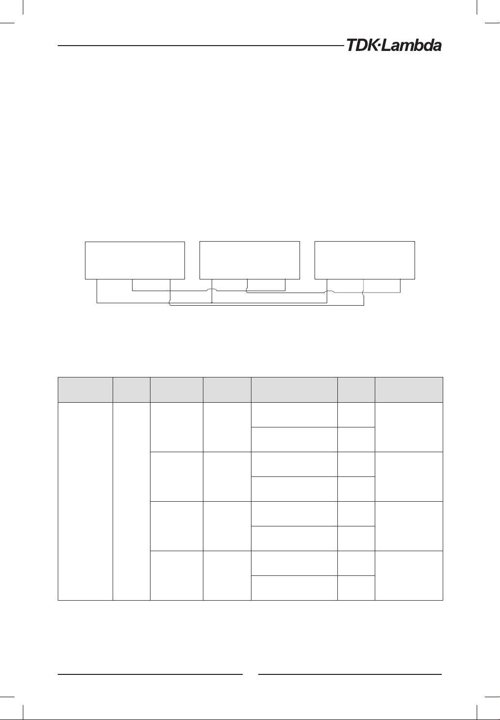
5.6 Daisy-Chain Connection
It is possible to configure a multiple power supply system to shut down all units when a fault
condition occurs in one of the units. When the fault is removed, the system recovers according to
a preset state: Safe start mode or Automatic restart.
Set signal ”SO” to positive logic via Front panel (refer to section 5.7.1) . If a fault occurs in one of
the units it’s ”PS_OK” signal will be set to low level and the display will indicate the fault. The other
units will shut off and their displays will indicate ”SO”. When the fault condition is removed, the
units will recover to their last setting according to their respective Safe start or Auto-restart setting.
Fig.5-6 shows connection of three units, however the same connection method applies to systems
with more units.
P OWE R S U PP LY
J3 -7
IFC _C OM PS_ OK
J3 -2
#1
J3 -5
SO
P OWE R S U PP LY
J3 -7
IFC _C OM PS_ OK
J3 -2
#2
J3 -5
SO
J3 -7
Fig.5-6: Daisy-Chain connection
5.7 Rear Panel (J3 Connector) Functions and Settings
Subsystem
Level
Rear Panel
Display
R
.
AN
Function
Level
Interlock
Shut OFF
Programmed
PIN 1
Display Parameter Level Display Description
Enable (ON)
I C
Disable (OFF)
Positive
SO
Negative
High
in1
Low
P OWE R S U PP LY
#3
J3 -2
IFC _C OM PS_ OK
ON
OFF
OS
NEG
Hi
o
J3 -5
SO
Enable/Disable
interlock
function (Analog
ON/OFF)
Positive (polarity)
same as PS_OK
signal
Open collector
Programmed
PIN 2
Table 5-3: Rear panel subsystem menu
in2
69
High
Low
Hi
Open collector
o
Page 70

5.7.1 External Shut Off Function
SO signal serves as Output Shut Off . It is an optically isolated signal from the power supply output.
Connection to the signal is made via pin J3-5 (Shut Off ) and pin J3-7 (IFC_COM). The SO pin accepts
a 4V to 15V signal or Open-Short contact to disable or enable the power supply output. The SO
function will be activated only when a transition from On to Off is detected after applying AC
power to the unit. Thus, in Auto start mode, the output will be enabled after applying AC power,
even if SO is in Off level. After On to Off transition is detected, the SO will enable or disable the
power supply output according to the signal level or the short/open applied to J3. When the
external SO is triggered, the power supply will display ”SO”on the voltage display but the PROT
LED will not illuminate.
The external shutdown is useful when using the power supply as part of a larger test system in
which digital or analog control is required or in ”Daisy-Chain”.
The SO control logic can be selected via the Front panel as follows:
1. Press MENU button. MENU (GREEN) LED illuminates. ”set” message appears on the Voltage
.
display and ”r
AN” message appears on the Current display.
2. Press Current encoder. The ”SO” message appears on the Current display.
3. Press the Current encoder again. The ”SO” message appears on the Voltage display. Parameter
”OS” or ”NEG” appears on the Current display.
4. Rotate and press the Current encoder to select the required parameter.
5. For signal details refer to Table 5-4.
SO logic SO signal level (J3-5 - J3-7) Output status
Positive (as PS_OK) (default) 4-15V or Open
0-0.6V or Short
Negative 4-15V or Open
0-0.6V or Short
On
Off SO
Off SO
On
Table 5-4: SO logic selection
5.7.2 Interlock Function - Analog On/Off. (Enable/Disable)
Interlock signal serves as Output Enable/Disable via switch or relay. Use the Interlock function to
enable or disable the output as emergency shutoff or door open switch. It is an optically isolated
signal from the power supply output. Connection to the signal is made via pin J3-4 (ILC) and pin
J3-7 (IFC_COM).
The ILC control logic can be selected via the Front panel as follows:
1. Press MENU button. MENU (GREEN) LED illuminates. ”set” message appears on the Voltage
.
display. ”r
AN” message appears on Current display.
2. Press Current encoder and the ”I C ” message appears on the display.
3. Press Voltage encoder and ”I C ” message appears on the display. The parameters ”OFF” or
”ON” appear on the Current encoder display.
4. Rotate and press the Current encoder to select desired parameter.
5. For signal details refer to Table 5-5.
70
Page 71
Front Panel ILC
Setting
OFF - Default Open or Short On Voltage/Current Off
ON
ILC Input
Open Off
Short On Voltage/Current Off
Power Supply
Output
Display Alarm LED
EnA
Blinking
Table 5-5: Interlock functions and settings
CAUTION:
To prevent possible damage to the unit, do not connect any of the Enable /Disable inputs to the
positive or negative output potential.
NOTE:
Safe Start mode - If the Interlock fault condition clears while units are in safe start mode, the power
supply stay to Off mode.
Auto Restart mode - The output will automatically return to previous settings.
5.7.3 Auxiliary Programmed Function Pin 1 and Pin 2
The programmed signal Pin 1 (J3-1) and Pin 2 (J3-6) are open collector, maximum input voltage
25V and maximum sink current 100mA, and can be controlled via Front panel or software.
Pin 1 or Pin 2 settings are made as follows:
.
1. Press MENU button. MENU (GREEN) LED illuminates. The ”r
AN” message appears on the
Current display.
2. Press Current encoder and the ”I C ” message appears on the Voltage display.
3. Rotate Voltage encoder until ”i n1 / i n2” message appears on display. Press Encoder to
select the desired Pin.
4. Voltage display shows the selected Pin number.
5. Rotate the Current encoder to toggle between ”Hi ” (High) or ”o” (Low).
6. Press Current encoder to select desired parameter.
7. Press MENU button twice to return display to it’s previous state. MENU LED turns OFF.
CAUTION:
Do not connect Pin 1 and Pin 2 to a voltage source higher than 25V. Always connect Pin 1 and Pin 2
to the voltage source with a series resistor to limit the sink current to less than 100mA.
71
Page 72

5.7.4 Power Supply OK Signal
PS_OK signal indicates fault condition in the power supply. It is a TTL signal output at J3-2,
referenced to IFC_COM at J3-7 (Isolated Interface Common). When a fault condition occurs, PS_OK
level is low, with maximum sink current of 1mA. When no fault condition occurs, PS_OK level is
high with maximum source current of 2mA. All conditions when output status is disabled sets
PS_OK to low level.
The PS_OK signal at high level can be delayed via Front panel setting. This function is used to
prevent signal rise before output reaches set value.
PS_OK delay setting:
.
1. Press MENU button. MENU (GREEN) LED illuminates. The ”r
Current display.
2. Press Current encoder, ”I C ” message appears on the Voltage Display.
3. Rotate Voltage encoder until ”Sd” message appears and press Encoder.
4. Parameter delay time in mSec appears on the Current display
5. Rotate the Current encoder to adjust the setting level. PS_OK delay range is from 0 to 9999mSec.
6. Press Current encoder to select desired level.
7. Press MENU button twice to return display to it’s previous state. MENU LED turns OFF.
AN” message appears on the
5.8 Rear Panel (J1 Connector) Functions
5.8.1 CV/CC Signal
The CV/CC signal indicates the operating mode of the power supply. Constant Voltage or Constant
Current. CV/CC signal is an open collector output with a 30V parallel zener, at J1-8, referenced to
the COM at J1-7 (connected internally to the negative sense potential). When the power supply
operates in Constant Voltage mode, CV/CC output is open. When the power supply operates in
Constant Current mode, CV/CC signal output is low (0-0.6), with maximum 10mA sink current.
CAUTION:
Do not connect CV/CC signal to a voltage source higher than 30VDC. Always connect CV/CC signal
to the voltage source with a series resistor to limit the sink current to less than 10mA.
72
Page 73
5.9 Parameter Setting Memory
Power Supply has four memory configuration modes:
Subsystem
Level
Memory
Display
MEMo
Function
Level
SAVE
RECALL
RST
FRST
Display
SAE
REC
RST
.
rst
F
Parameter
Level
1…4
1…4
YES
YES
Display Description
...
4
1
1
es
es
Save setting in non violate memory
...
4
Recall setting in non violate memory
Reset setting
Set factory default setting
Table 5-6: Parameter Setting Memory
5.9.1 Default Setting
For factory default parameters refer to Table 5-7.
1. Press MENU button. MENU (green) LED illuminates. ”set” message appears on the Voltage
display.
2. Rotate Voltage encoder until ”MEMO” message appears on Voltage display.
3. Press Voltage encoder. ”se” message appears on Voltage Display.
.
4. Rotate Voltage encoder until ”F
5.
Press Voltage encoder. ”F.rs t” message appears on Voltage Display, and ” es” appears on Current
rs t” message appears on Voltage display.
display .
6. Press the Current encoder ”HOd” Message appears on the display for 1sec. The display blinks
once and returns to previous level.
7. Press MENU button twice to return display to previous state, MENU LED turns OFF.
NOTE:
No response for FRST command. After this command the power supply loses communication because
of communication setting change.
5.9.2 Reset
For Reset parameters refer to Table 5-7.
1. Press MENU button. MENU (green) LED illuminates. ”set” message appears on the Voltage
display.
2. Rotate Voltage encoder until ”MEMO” message appears on Voltage display.
3. Press Voltage encoder. ”se” message appears on Voltage Display.
4. Rotate Voltage encoder until ”rst” message appears on Voltage display.
5. Press Voltage encoder. ”rs t” message appears on Voltage Display. ”es” appears on the
Current display .
6. Press the Current encoder, display blinks and returns to previous level.
7. Press MENU button twice to return display to previous state, MENU LED turns OFF.
5.9.3 Last Setting Memory
Memory stores last set parameters when AC switch is turned off.
For last set parameters refer to Table 5-7.
73
Page 74

5.9.4 Save <1..4>
This command saves the present state of the power supply to a specified location in memory
(refer to Table 5-7). Up to 4 states can be stored. Storage locations 1 through 4 are in nonvolatile
memory.
Save Front panel setting:
1. Press MENU button. MENU (green) LED illuminates. ”set” message appears on the Voltage
display.
2. Rotate Voltage encoder until ”MEMO” message appears on Voltage display.
3. Press Voltage encoder. ”se” message appears on Voltage display.
..
4. Press Voltage encoder. ”SA e” message appears on Voltage display. Numbers ”1
on Current display.
5. Rotate the Current encoder to select required number value and then press the Current
encoder. Display blinks and returns to previous level.
5.9.5 Recall <1..4>
This command recalls the present state of the power supply from a specified location in memory
(refer to Table 5-7). Up to 4 states can be stored. Storage locations 1 through 4 are in nonvolatile
memory.
Recall front panel setting:
1. Press MENU button. MENU (green) LED illuminates. ”set” message appears on the Voltage
display.
2. Rotate the Voltage encoder until ”MEMO” message appears on Voltage display.
3. Press Voltage encoder. ”Re C” message appears on Current display.
..
4. Press Current encoder. Numbers ”1
5. Rotate the Current encoder to select required number value and then press the Current
encoder. Display blinks and returns to previous level.
4” appear on Current display.
4” appear
74
Page 75
Parameter Factory Default Resetting Last setting Save & Recall
Output Status OFF OFF + +
Voltage Set-point 0V 0V + +
Current Set-point MAX 0A + +
Fold Back mode OFF OFF + +
Over Voltage Protection
OVP
Under Voltage Level/
Protection mode
Under Voltage Level/
Protection level
Auto Start Mode SAFE SAFE + +
Control pin 1 1 1 + +
Control pin 2 1 1 + +
Input Trigger Source EXT EXT + Protection Delay 0mS 0mS + +
Voltage Programming
Mode
Current Programming
Mode
Programming and Monitor
Range
Current Share Mode
{Master|Slave}
Interlock (Inhibit) OFF (disabled) OFF (disabled) + Shutdown Logic 1 (positive) - + Remote mode LOC LOC + +
Communication Mode RS232 - + Address 6 - + Baud Rate 9600 - + Language SCPI - + Lock/unlock front panel Unlock - + LIST and WAVE subsystems OFF OFF - Program Step AUTO AUTO (COUNT 1) - Trigger Out OFF OFF + +
PS_OK delay 0mS 0mS + +
Enable registers Clear Clear - Event registers Clear Clear - -
MAX MAX + +
OFF (UVL) OFF (UVL) + +
0V 0V + +
Digital - + -
Digital - + -
5V - + -
(Master H1) - + -
Table 5-7: Memory parameters.
75
Page 76
CHAPTER 6: REMOTE ANALOG PROGRAMMING
6.1 Introduction
The Rear Panel connector J1 allows the user to program the power supply output voltage and
current limit with an analog device. J1 also provides monitoring signals for output voltage and
output current. The programming range and monitoring signals range can be selected between
0-5V or 0-10V using the Front Panel Menu Subsystem Level.
Subsystem
Level
SET
Display
set
Function
Level
Voltage limit
source
Current limit
source
Source and
monitor range
Display Parameter Level Display Description
.
AN
F
E
E
F
E
E
Parameter settings in Analog/
.
O
Digital control mode, Voltage
.
RES
.
AN
Parameter settings in Analog/
.
O
Digital control mode, Current
.
RES
Control by external Voltage/
5
channel.
channel.
Resistor, Range 5/10
OT
CvRR
RNG
Front Panel (Digital)
Ext. Voltage
Ext. Resist.
Front Panel (Digital)
Ext. Voltage
Ext. Resist.
5/10 (V/KΩ) range
Table 6-1: MENU. Analog Programming Setting
CAUTION:
COM (J1-7,9) and VPGM_RTN (J1-12) terminals of J1 are connected internally to the -Sense potential (-S).
Do not connect these terminals to any potential other than -Sense (-S), as it may damage the power supply.
6.2 Local/Remote Analog Control
Contact J1-1 (Fig.4-3, item 1) accepts TTL signal or Open-Short contact (Referenced to J1-7,9) to
select between Local or Remote Analog programming of the output voltage and current limit. In
Local mode, the output voltage and current limit can be programmed via the front panel Voltage
and Current encoders or via the Communication interface. In Remote Analog mode, the output
voltage and current limit can be programmed by analog voltage or by programming resistors via
J1 contacts 6 and 5. Refer to Analog Programming Setting Table 6-2.
6.3 Local/Remote Analog Indication
Contact J1-4 (Fig.4-3, item 4) is an open collector output that indicates if the power supply is in
Local mode or in Remote Analog mode. To use this output, connect a pull-up resistor to a voltage
source of 30Vdc maximum. Choose the pull-up resistor so that the sink current will be less than
5mA when the output is in low state. J1-4 signal will be low if J1-1 is low and at least one of Analog
control modes are selected. Refer to Analog Programming Setting Table 6-2.
J1-1 LOC/REM SELECT Front Panel selection Front Panel selection J1-4 LOC/REM MON
OPEN
”1”
TTL ”0” or Short
Table 6-2: Local/Remote Analog Control and Indication
Not applicable Not applicable Open
.
AN F.AN
F
F
.
.
O or E.RES
E
.
AN
.
O or E.RES E.O or E.RES 0~0.6V
E
AN
.
O or E.RES 0~0.6V
E
Open
0~0.6V
76
Page 77
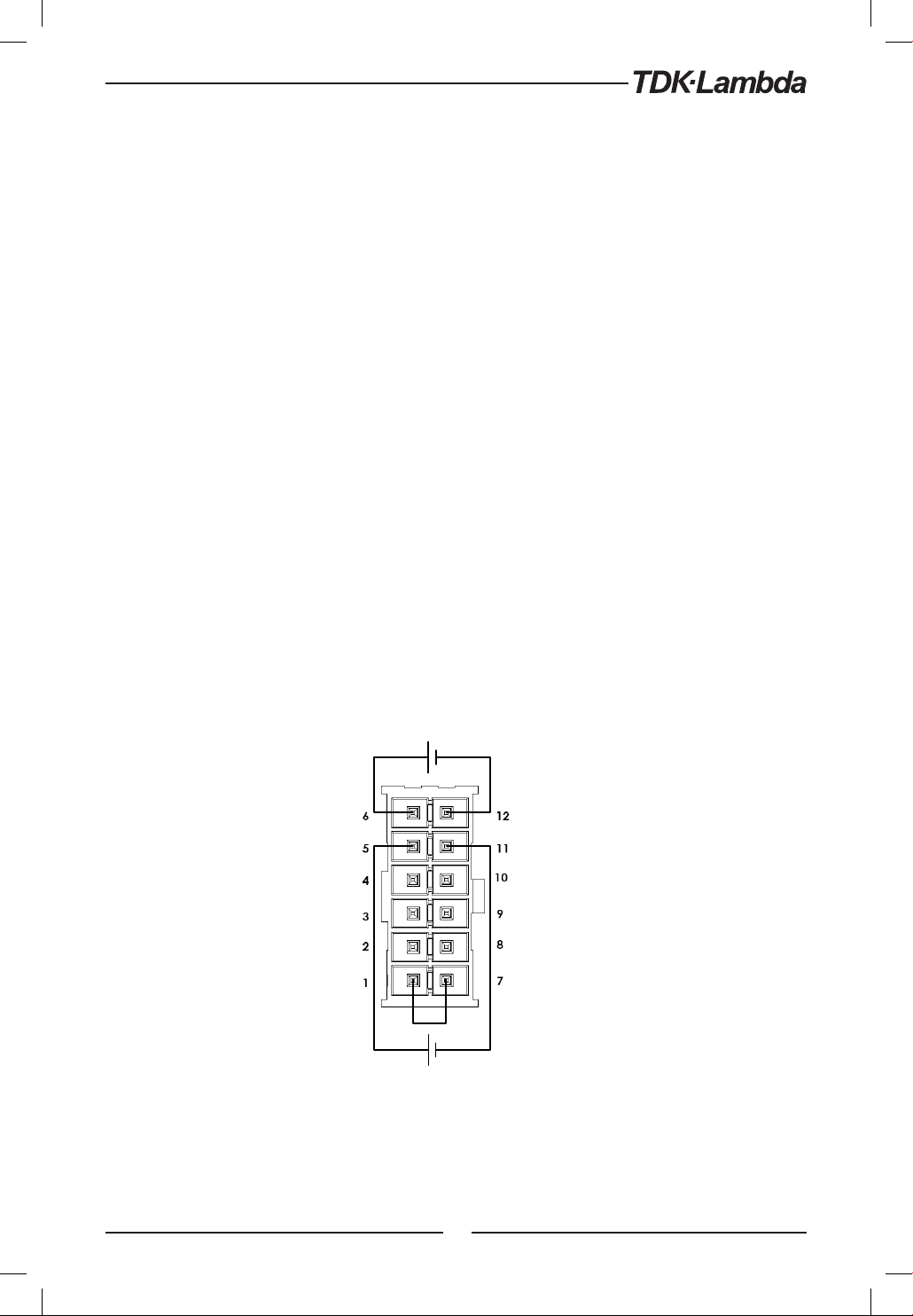
6.4 Remote Voltage Programming of Output Voltage and Current
Remote Programming settings are as follows:
1. For Voltage Analog Programming wiring refer to Fig.6-1.
2. Short pins J1-1 to J1-7.
3. Press MENU button. MENU (GREEN) LED illuminates. ”Set” message appears on Voltage display.
4. Press Voltage encoder. ”O t” message appears on Voltage Display and ”Cv RR” appears on
the Current display.
5. Press Voltage encoder to select programming of the Output Voltage, or press Current encoder
to select programming of the Output Current.
.
6. The selected function appears on the Voltage display. Parameter ”F
appears on the Current display.
7. Rotate and press the Current encoder to select ”E.O”.
8. ” O t” message appears on Voltage Display and ”Cv RR” appears on the Current display.
9. Rotate Voltage encoder until ”rNG” appears on display. Press on the relevant Encoder.
10. ”rA NG” appears on Voltage display and ”5” (5V) or ”10” (10V) appears on Current display.
11. Rotate and press the Current encoder to select the desired programming Voltage range.
12. Press MENU button twice to return display to it’s previous state. MENU LED turns OFF
CAUTION:
To maintain the isolation of power supply and prevent ground loops, use an isolated programming
source when operating the power supply via remote analog programming at J1 connector.
N” or ”E.O” or ”E.res”
Output Voltage
Programming
Output Current
Programming
Fig.6-1: J1-Remote Voltage Programming Connection
*Max. output current is limited by front panel current setting.
*
77
Page 78
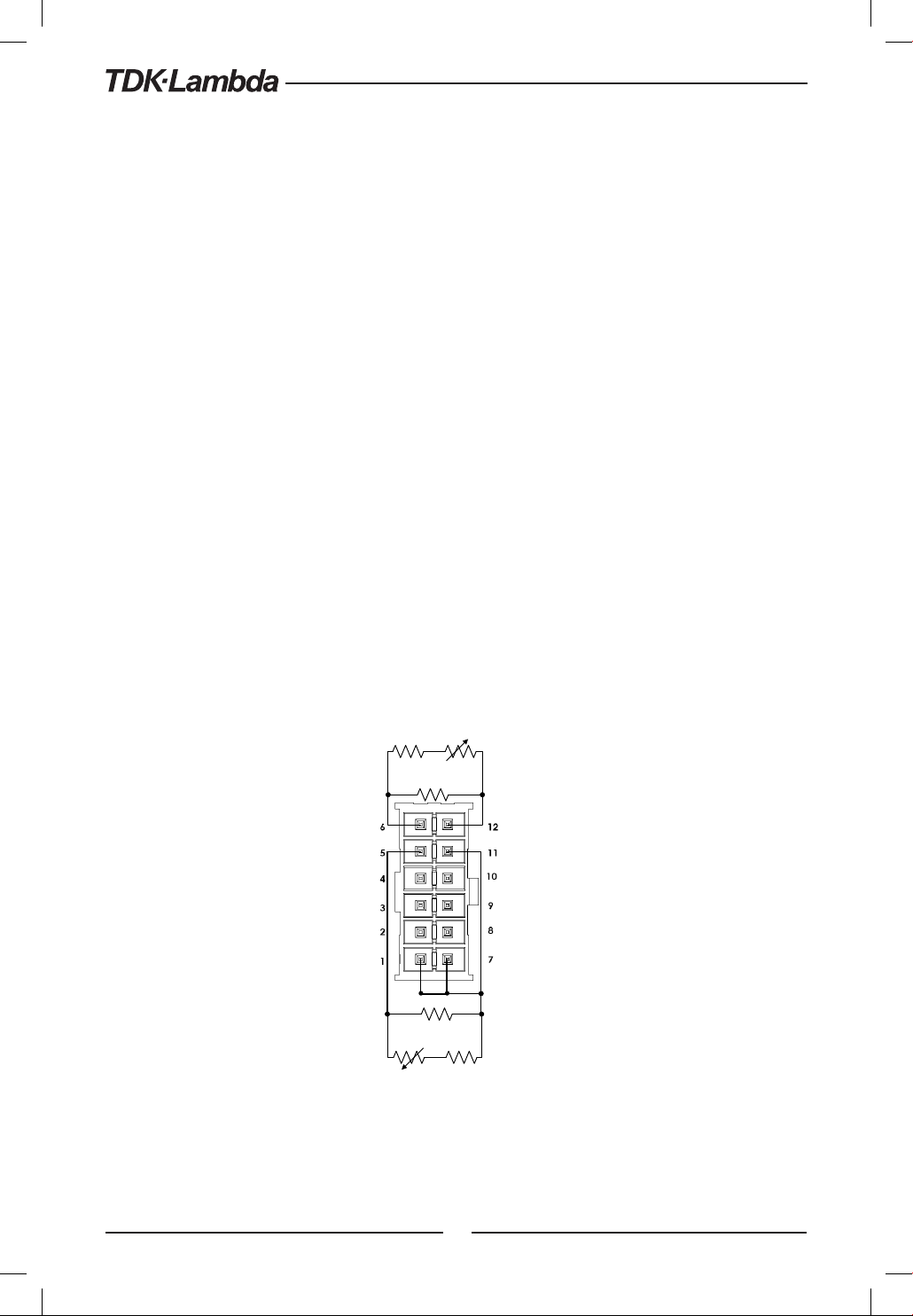
6.5 Remote Resistor Programming of Output Voltage and Output Current
For resistive programming, internal current sources, for output voltage and/or output current
control, supply 1mA current through external programming resistors connected between J1-6
and J1-12 and between J1-5 and J1-1, J1-7 & J1-11. The voltage across the programming resistors
is used as a programming voltage for the power supply. Resistance of 0~5Kohm or 0~10Kohm
can be selected to program the output voltage and current limit from zero to full scale. A variable
resistor can control the output over the entire range, or a combination of variable resistors and
series/parallel resistors can control the output over restricted portion of the range.
Remote Programming settings as follows:
1. For Resistor Analog Programming wiring refer to Fig.6-2.
2. Short pins J1-1 to J1-7.
3. Press MENU button. MENU (GREEN) LED illuminates. ”Set” message appears on Voltage display.
4. Press Voltage encoder. ”O t” message appears on Voltage Display and ”Cv RR” appears on
the Current display.
5. Press on the Voltage encoder to select programming the Output Voltage, or Press Current
encoder to select programming of the Output Current.
6. The selected function appears on the Voltage display. Parameter ”F.N” or ”E.O” or ”E.res”
appears on the Current display.
7. Rotate and press the Current encoder on to select ”E.res”.
8. ” O t” message appears on Voltage Display and ”Cv RR” appears on the Current display.
9. Rotate Current encoder until ”rNG” appears on the display. Press on the relevant Encoder.
10. ”rA NG” appears on Voltage display and ”5” (5K) or ”10” (10K) appears on Current display.
11. Rotate and press the Current encoder to select the desired programming Resistance range.
12. Press MENU button twice to return display to the previous state. MENU LED turns OFF.
Output Voltage
Programming
Optional sets
Upper limit
Optional sets
Upper limit
Resistor
Output Current*
Programming
Programming
Resistor
Optional sets
Lower limit
Optional sets
Lower limit
Programming
Fig.6-2: J1-Remote Resistor Programming Connection
*Max. output current is limited by front panel current setting.
78
Page 79

NOTES:
1. In Remote analog mode: the output voltage cannot be set by the Voltage encoder.
The output voltage limit is set to 5% over the model-rated maximum value. The output Current
limit is set by the Current encoder to 5% over the model-rated maximum value.
2. The power supply will operate within the extended range, however it is not recommended to
operate the power supply over its voltage and current rating and performance is not guaranteed.
3. Communication: In Remote analog mode, power supply parameters can be programmed and
read back via the Communication port except output voltage and current settings.
4. To maintain the temperature stability specification of the power supply, the resistors used
for programming should be stable and low noise resistors, with a temperature coefficient of less
than 50ppm.
5. Radiated emissions, FCC requirements: FCC requirements for radiated emissions, use a shielded
cable for the analog control signals. In cases using a non shielded cable, attach an EMI ferrite
suppressor to the cable, as close as possible to the power supply.
6. Front panel PREV button: Use PREV button to display the output voltage and current settings
defined by the Encoders or Communication.
6.6 Programming Monitoring of Output Voltage (V_MON) and Current (I_MON)
The J1 connector, located on the rear panel provides analog signals for monitoring the output
voltage and output current. Selection of the voltage range between 0-5V or 0-10V is made via
Front Panel.
The monitoring signals represent 0 to 100% of the power supply output voltage and output
current. The monitor outputs have 500 ohm series output resistance.
Ensure that the sensing circuit has an input resistance of greater than 500 Kohm or accuracy
will be reduced.
Range selection as follows:
1. Press MENU button. MENU (GREEN) LED illuminates. ”Set” appears on Voltage display.
2. Press Voltage encoder. ” Ot” message appears on Voltage Display and ”CvRR” appears on
the Current display.
3. Rotate Voltage encoder until ”rNG” appears on display. Press on the relevant Encoder.
4. ”rAN G” appears on Voltage display and ”5” (5V) or ”10” (10V) appears on Current display.
5. Rotate and press the Current encoder to select the desired monitoring Voltage range.
6. Press MENU button twice to return display to the previous state. MENU LED turns OFF.
79
Page 80
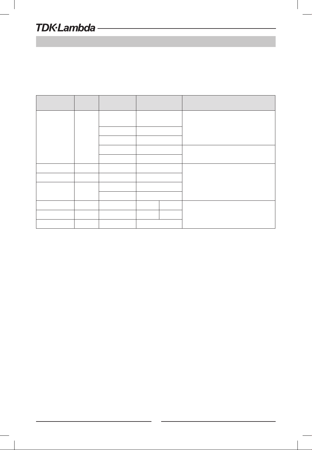
CHAPTER 7: Serial RS232/RS485 and USB Interface
7.1 Introduction
This chapter describes the set-up, operation, commands and communication protocol of Z+ power
supplies via serial communication interfaces: RS232, RS485 or USB.
7.2 Configuration
Function Level Display
Interface
Address
Baud Rate
Language
IP Address
INt
ADR
Bd
ANG
I
MC
LAN Reset
RST
Parameter
Level
232
485
USB
LAN
IEEE
1….31
1200..57600
SCPI
GEN
IP1---IP4
MAC1-MAC6
Yes
Table 7-1: Front panel setup
7.2.1 Default Setting
Refer to Table 5-7: Memory parameters.
Display Description
232
45
sb
n
IEEE
1
...
31
Available only if IEEE or LAN option installed
5.
SC I
GEN
I 2 10
MAC 3345
Available only if LAN option installedMAC Address
es
7.2.2 Address Setting
The power supply address can be set to any address between 1 and 31.
1. Press REM button. The REM LED illuminates. ”dr” message appears on the Current display.
2. Press Current encoder. Voltage display shows ”dr” and Current display shows present address.
3. Rotate the Current encoder to select required address.
4. Press Current encoder to enter selected parameter to memory.
5. When parameter is accepted the display blinks once and returns to the previous level.
7.2.3 Communication Interface Selection
+
power supply can be configured for RS232, RS485 or USB(*) communication interface.
Z
1. Press REM button. The REM LED illuminates. ”IN t ” message appears on the Voltage display.
2. Press Voltage encoder. Voltage display shows ”IN t ” and Current display shows communication
interface.
3. Rotate the Current encoder to select the required interface.
4. Press Current encoder to enter selected parameter to memory.
5. When parameter is accepted the display blinks once and returns to the previous level.
* Do not connect or disconnect the USB cable when the PS is operating.
80
Page 81

7.2.4 Baud Rate Setting
Seven optional rates are possible: 1200, 2400, 4800, 9600, 19200, 38400, 57600.
1. Press REM button. The REM LED illuminates. ”IN t ” message appears on the Voltage display.
2. Rotate Voltage encoder until Voltage display shows ”bd”.
3. Press Voltage encoder. Voltage display shows ”bd” and Current display shows baud rate.
3. Rotate the Current encoder to select required baud rate.
4. Press Current encoder to enter selected parameter to memory.
5. When parameter is accepted the display blinks once and returns to the previous level.
7.2.5 Language Selection (RS232/RS485, USB)
+
implements SCPI standard command line interface to remotely control the power supply.
The Z
Additionally, a small subset of legacy GEN commands has been provided for ease of use and
backwards compatibility.
1 Press REM button. The REM LED illuminates. ”IN t ” message appears on the Voltage display.
2. Rotate Voltage encoder until Voltage display shows ”AN G”.
3. Press Voltage encoder. Voltage display shows ”AN G” and Current display shows language.
3. Rotate the Current encoder to select required language.
4. Press Current encoder to enter selected parameter to memory.
5. When parameter is accepted the display blinks once and returns to the previous level.
7.2.6 Setting Unit in Remote, Local Lockout or Local Mode
Local mode:
When the power supply is in local mode, it can receive queries. If a query is received, the power
supply will reply and remain in Local mode. Serial commands may be sent to set and read the
status registers while the unit is in Local mode. If the Enable registers are set the power supply
will transmit SRQ’s while in Local mode.
Remote mode:
If a command is received that affects the output or a Remote command is received, the power
supply will perform the command and change to Remote mode.
When the power supply is in Remote mode, REM LED illuminates and parameters cannot be
changed via the front panel. Return to Local mode by pressing the front panel REM Button or via
communication command.
Local Lockout mode:
When the power supply is in Local Lockout mode, REM LED illuminates and parameters cannot be
changed via the front panel. It is possible to return to Remote mode, only with a communication
command or by AC power recycle.
81
Page 82
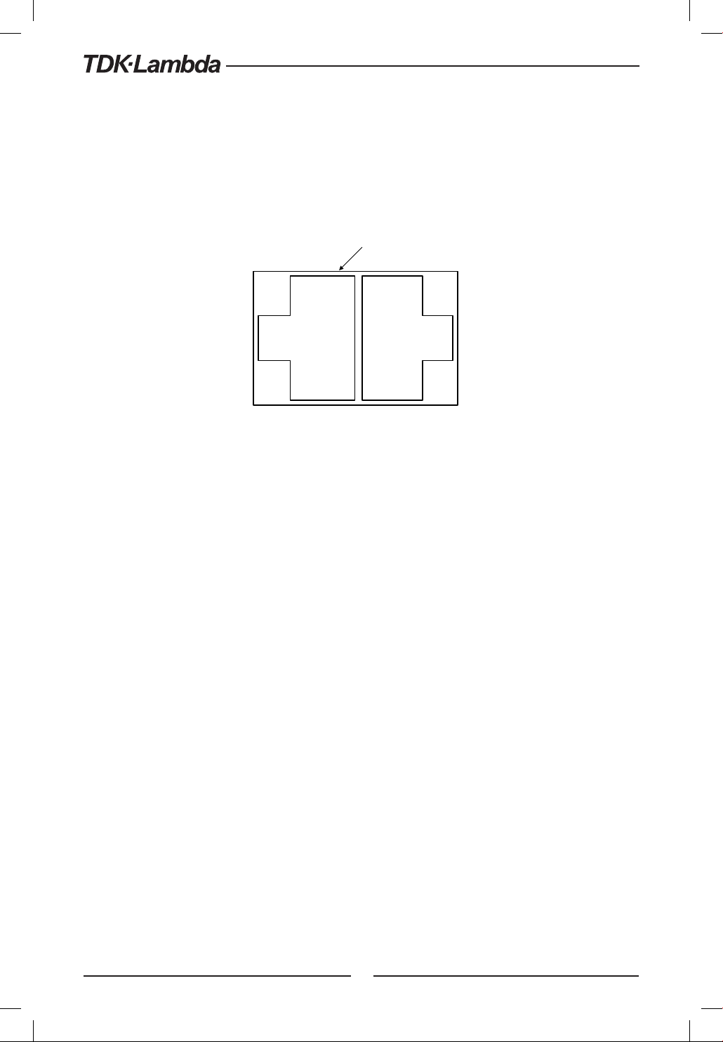
7.3 Rear Panel RS232/485 Connector
The RS232/485 interface is accessible through the Rear panel RS232/485 IN and RS485 OUT
connectors. The connectors are 8 contact RJ-45. The IN and OUT connectors are used to connect
power supplies in a RS232 or RS485 chain to a controller. Refer to Fig.7-1 for IN/OUT connectors.
Shield
(Connector enclosure)
NC 8
NC 7
TXD- 6
RXD- 5
RXD+ 4
TXD+ 3
NC 2
SG 1
Fig.7-1: J4 rear panel IN/OUT connectors pinout
1 SG
2 NC
3 RXD+
4 TXD+
5 TXD6 RXD7 TX
8 RX
INOUT
NOTE:
Tx and Rx are used for RS232 communication. Txd +/- and Rxd +/- are used for RS485 communication.
Refer to RS232 and RS485 cable descriptions for connection details.
82
Page 83
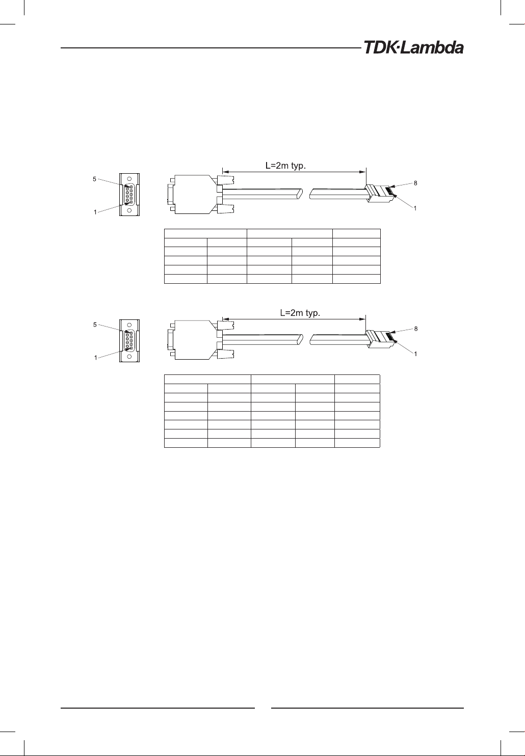
7.4 Connectig Power Supply To RS232 Or RS485 BUS
Connect rear panel IN connector to the controller RS232 or RS485 port using a suitable shielded
cable. Refer to Figures 7-3 and 7-4 for available RS232 and RS485 cables.
Socket
Socket
DB-9 CONNECTOR 8 PIN CONNECTOR REMARKS
PIN NO. NAME PIN NO. NAME
HOUSING SHIELD HOUSING SHIELD
2 RX 7 TX TWISTED
3 TX 8 RX PAIR
5 SG 1 SG
Fig.7-3: RS232 cable with DB9 connector (P/N: Z-232-9)
DB-9 CONNECTOR 8 PIN CONNECTOR REMARKS
PIN NO. NAME PIN NO. NAME
HOUSING SHIELD HOUSING SHIELD
9 TXD- 6 RXD- TWISTED
8 TXD+ 3 RXD+ PAIR
1 SG 1 SG
5 RXD- 5 TXD- TWISTED
4 RXD+ 4 TXD+ PAIR
Fig.7-4: RS485 cable with DB9 connector (P/N: Z-485-9)
83
Page 84
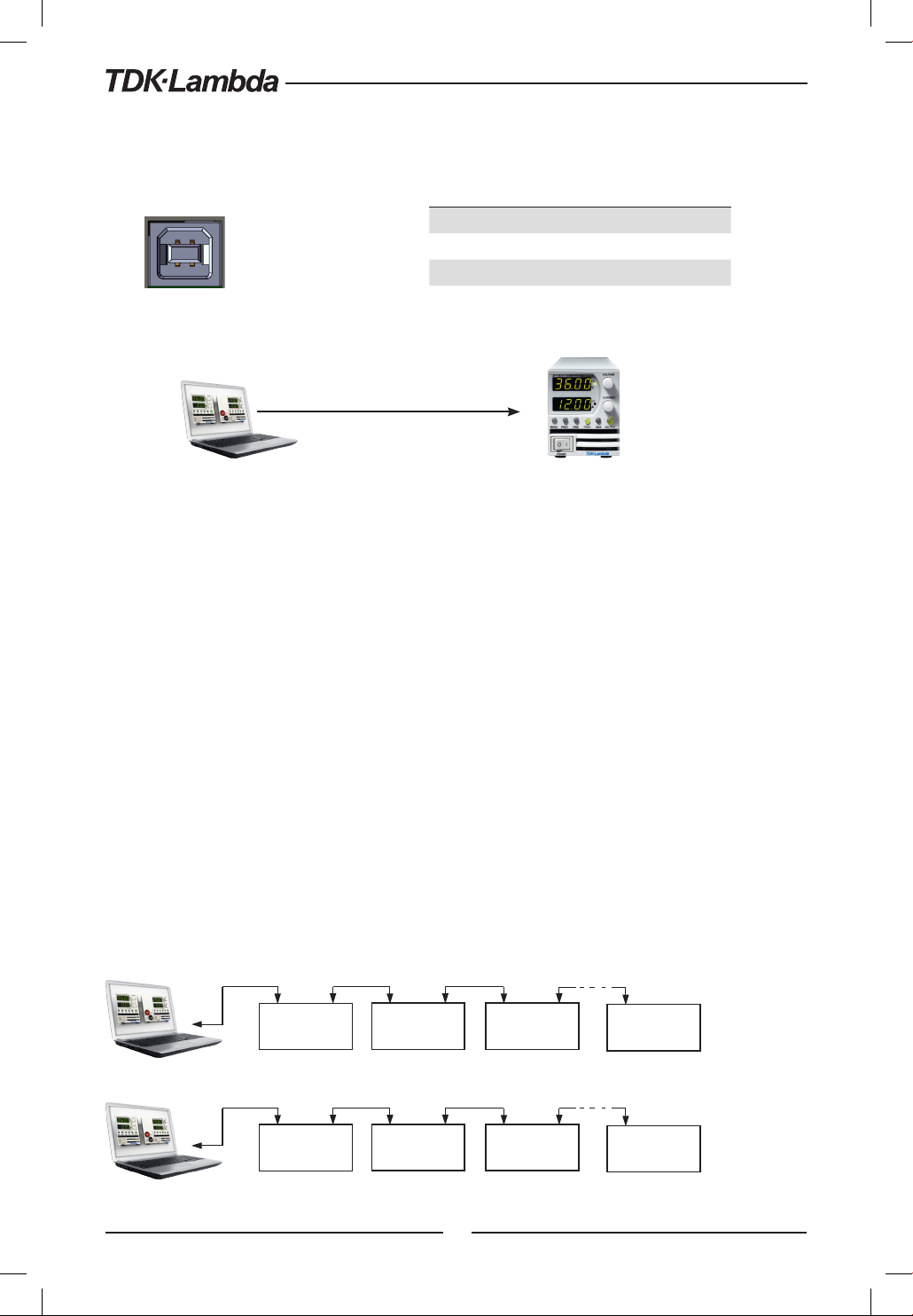
7.5 Rear Panel USB Connector
1 2 3
4
A standard USB Series B device connector is located on Rear panel for USB control. Refer to Fig.7-5
and Table 7-2.
Fig.7-5: USB Connector
7.5.1 USB Getting Started
USB Cable (*)
The following steps will help you quickly get started connecting your USB-enabled instrument to
the Universal Serial Bus (USB):
1. Verify AC switch is OFF.
2. Connect Z+ to the USB port on the computer.
3. Turn AC switch ON.
4. Insert the software CD-ROM that is shipped with the product to your CD-ROM Drive.
The Z+ drivers selection menu will automatically appear. click on the ICON ”USB drivers”.
Install the USB Driver.
* Do not connect or disconnect the USB cable when the PS is operating.
* In case of USB Communication loss following steps should be applied:
1. Turn AC switch OFF 2. Close Z+ COM port
3. Turn AC switch ON 4. Open Z+ COM port
Pin Designator Description
1 VBUS +5 VDC
2 D- Data 3 D+ Data +
4 GND Interface com
Table 7-2: USB connector pin out
connect to
USB port
NOTE:
7.6 Multi Power Supply Connection to RS232 Or RS485 or USB
A Daisy-chain configuration of up to 31 units can be connected to RS232, RS485 or USB . The first
unit connects to the controller via RS232, RS485 or USB and other units are connected with a
RS485 bus. The user must set all slave power supplies to a unique address. No two power supplies
may have the same address.
1. First unit connection: Select communication Interface. Refer to section 7.2.3.
2. Other unit connections: The other units on the bus are connected via their RS485 interface.
Refer to Figures 7-6 and 7-7 for typical connections.
3. Using the Linking cable supplied with each unit (Refer to Fig.7-8), connect each unit OUT
connector to the next unit IN connector.
RS232/485
IN IN
POWER SUPPLY
Fig.7-6: Multi power supplies RS232/485 connection
USB
IN IN
POWER SUPPLY
RS485
OUT OUT
POWER SUPPLY
#1
RS485
OUT OUT
POWER SUPPLY
#1
Fig.7-7: Multi power supplies USB connection
RS485
IN
#2
#2
POWER SUPPLY
#3
RS485
IN
POWER SUPPLY
#3
OUT
OUT
RS485
RS485
IN
OUT
POWER SUPPLY
#31
IN
OUT
POWER SUPPLY
#31
84
Page 85
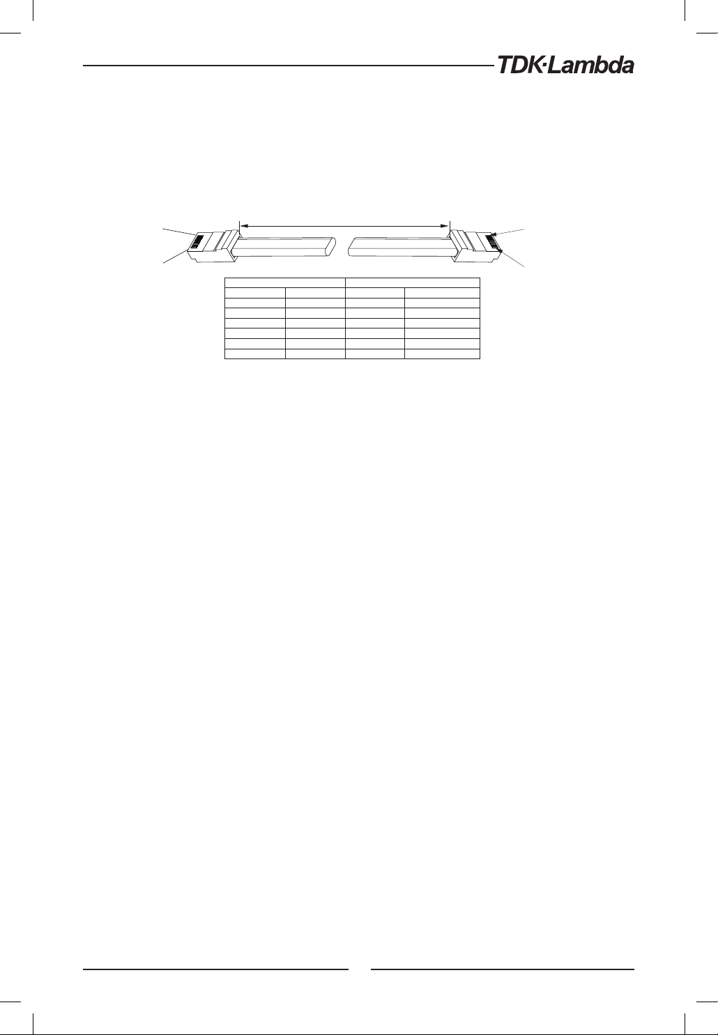
#1
#2
#3
RS232/485
RS485
RS485
RS485
RS485
120 OHM
#31
1
NOTES:
It is recommended when using ten or more power supplies in Daisy-chain system to connect
120Ω resistive termination at the last unit’s RS-485 out connector
120Ω, 0.5W between TXD+ and TXD-.
120Ω, 0.5W between RXD+ and RXD-.
1
8
8 PIN CONNECTOR (IN) 8 PIN CONNECTOR (OUT)
PIN NO. NAME PIN NO. NAME
HOUSING SHIELD HOUSING SHIELD
1 SG 1 SG
6 TXD- 6 RXD3 TXD+ 3 RXD+
5 RXD- 5 TXD4 RXD+ 4 TXD+
L=0.5m typ.
8
Fig.7-8: Serial link cable with RJ-45 shielded connectors (P/N: Z-RJ45)
7.7 GEN Protocol (GEN series communication language)
NOTE:
The address (ADR n) command must return an ”OK” response before any other commands are accepted.
7.7.1 Data Format
Serial data format is 8 bit, one start bit and one stop bit. No parity bit.
7.7.2 End of Message
The end of message is the Carriage Return character (ASCII 13, 0x0D). The power supply ignores
the Line Feed (ASCII 10, 0x0A) character.
7.7.3 Command Repeat
The backslash character ”\” will cause the last command to be repeated.
7.7.4 Checksum
The user may optionally add a checksum to the end of the command. The checksum is ”$” followed
by two hex characters. If a command or a query has checksum, the response will also have one.
There is no CR between the command string and the ”$” sign. Example: STT?$3A STAT?$7B
7.7.5 Acknowledge
The power supply acknowledges received commands by returning ”OK” message. If an error is
detected, the power supply will return an error message. The rules for checksum also apply to
the acknowledge feature.
7.7.6 Backspace
The backspace character (ASCII 8) clears the last character sent to the power supply.
7.7.7 Error Messages
The power supply will return error messages for illegal commands and illegal programming
parameters. Refer to Table 7-3 for programming error messages and Table 7-4 for command error
messages.
85
Page 86
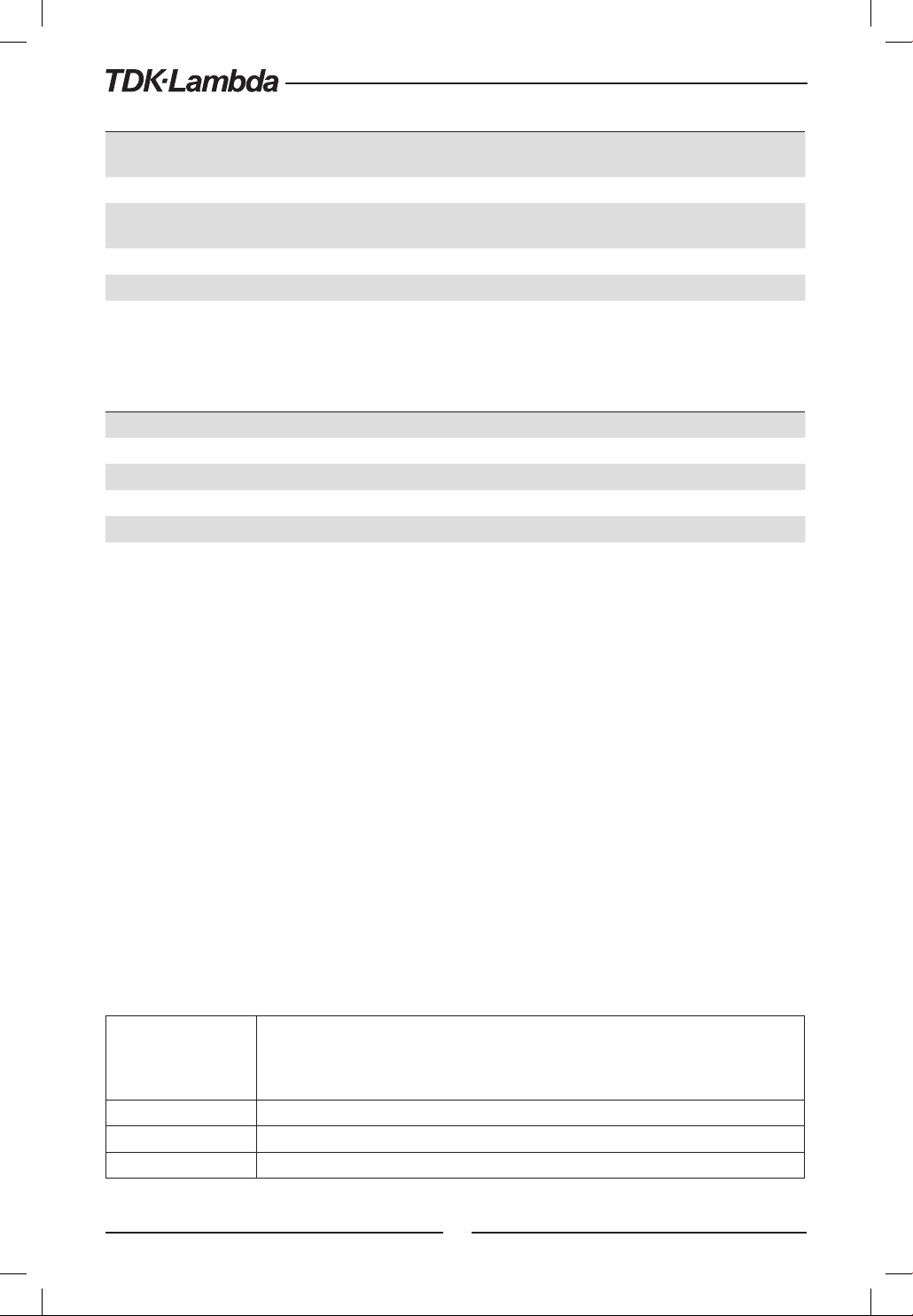
Error Code Description
E01 Returned when program voltage (PV) is programmed above acceptable range.
Example: PV above 95% of OVP setting.
E02 Returned when programming output voltage below UVL setting.
E04 Returned when OVP is programmed below acceptable range.
Example: OVP value is less than 105% of voltage setting.
E06 Returned when UVL value is programmed above the programmed output voltage.
E07 Returned when programming the Output to ON during a latched fault shut down.
E08 Cannot execute command via Advanced Slave Parallel mode.
Table 7-3: Programming error messages
Error Code Description
C01 Illegal command or query
C02 Missing parameter
C03 Illegal parameter
C04 Checksum error
C05 Setting out of range
Table 7-4: Commands error messages
7.8 GEN Command Set Description
7.8.1 General guides
1. Any command or argument may be in capital letters or small letters.
2. In commands with an argument, a space must appear between the command and the
argument.
3. For any command that sets a numeric value, the value may be up to 12 characters long.
4. Carriage Return: If the CR character (ASCII 13) is received by itself, the power supply will respond
with ”OK” and CR.
7.8.2 Command Set Categories
The command set is divided into four categories as follows:
1. Identification Commands
2. Initialization Commands
3. Output Commands
4. Global Commands
5. Auxiliary Commands
6. Status Commands
7.8.3 Identification Commands
Returns the power supply model identification as an ASCII string:
IDN?
REV? Returns the software version as an ASCII string. Current rev: ”REV:1.0”
SN? Return power supply serial number. Up to 12 characters in any format.
DATE? Returns date of last calibration. Format ”yyyy/mm/dd”. Example ”2009/12/17”
Default: ”TDK-Lambda,ZX-Y” (one comma, no spaces)
X = rated output voltage
Y = rated output current
86
Page 87
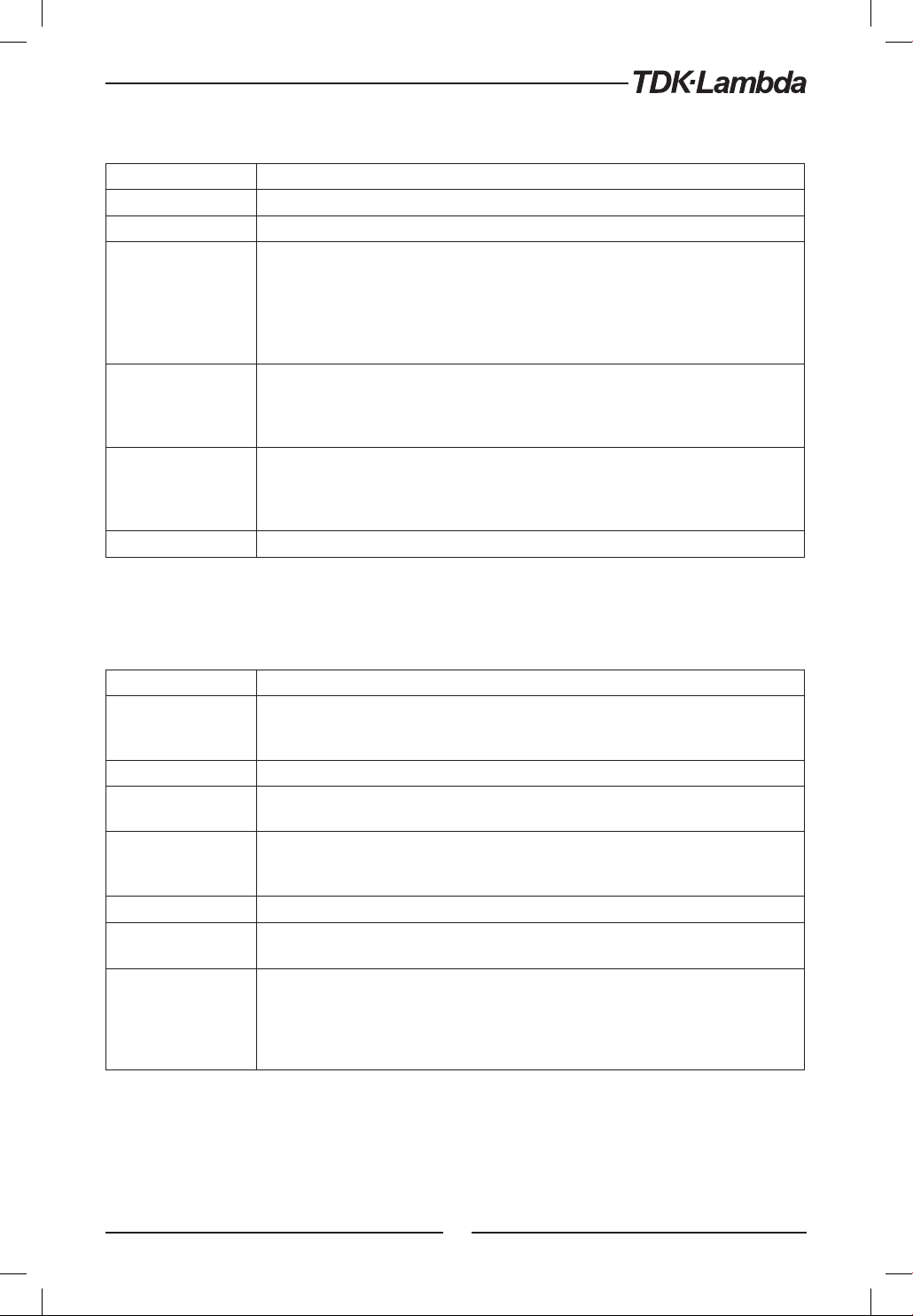
7.8.4 Initialization Commands
Command Description
ADR n ADR is followed by address which can be 1 to 31 and is used to access the power supply .
CLS Clear status. Sets FEVE and SEVE registers to zero.
Reset command. Brings the power supply to a safe and known state:
Output voltage: zero, Remote: non-latched remote,
RST
RMT
RMT?
\ Repeat last command. If \<CR> is received, the power supply will repeat the last command.
Output current: zero, Auto-start: Off,
Output: Off, OVP: maximum,
FOLD: Off, UVL: zero
The conditional registers (FLT and STAT) are updated, the other registers are not changed.
Sets the power supply to local or remote mode:
1. RMT 0 or RMT LOC, sets the power supply to Local mode.
2. RMT 1 or RMT REM, sets the unit to remote mode.
3. RMT 2 or RMT LLO, sets the unit to Local Lockout mode (latched remote mode).
Returns the Remote mode setting:
1. ”LOC”- The unit is in Local mode.
2. ”REM”- The unit is in Remote mode.
3. ”LLO”- The unit is in Local Lockout (latched remote) mode.
7.8.5 Output Commands
Command Description
Sets the output voltage value in Volts. The range of voltage value is described in Table 7-5.
PV n
PV? Reads the output voltage setting. Returns 6 digit string.
MV?
PC n
(See Note 1)
PC? Reads the output current setting. Returns 6 digit string.
MC?
(See Note 2)
DVC?
The maximum number of characters is 12. See the following examples for PV n format: PV
12, PV 012, PV 12.0, PV 012.00, etc...
Reads the actual output voltage. Return 6 digit string.
Example: 60VDC supply sends 01.150, 15.012, 50.000, etc...
Sets the output current value in Amperes. The range of current values are described in
Tables 7-6... 7-9. The maximum number of characters is 12. See the following examples for
PC n format: PC 10, PC 10.0, PC 010.00, etc...
Reads the actual output current. Returns 6 digit string.
Example: 72A supply sends 72.000, 20.140, 04.120, etc...
Display Voltage and Current data. Data will be returned as a string of ASCII characters.
A comma will separate the different fields.
The fields, in order, are: Measured Voltage, Programmed Voltage, Measured Current,
Programmed Current, Over Voltage Set point and Under Voltage Set Point.
Example: 60V-10A supply sends: 60.0000, 60.0000, 05.0000, 05.0000. 66.00.00.00
87
Page 88
Command Description
OUT n
OUT?
FLD n
FLD?
FBD nn
FBD? Supply returns the value of the added Fold Back Delay.
FBDRST Reset the added Fold Back Delay to zero.
OVP n
OVP?
OVM Sets OVP level to the maximum level. Refer to Table 7-9.
UV? Returns the under voltage mode UVP or UVL.
UVL n
UVL?
UVP n
UVP?
AST n
AST? Returns the string auto-restart mode status.
SAV n Saves present settings to specified location in memory (n=1...4).
RCL n Recalls saved settings from specefied location in memory (n=1...4).
MODE?
PMS n
PMS?
Turns the output to ON or OFF. Recover from Safe-Start, OVP or FLD fault. OUT 1 (or OUT
ON)-Turn On.
Returns the output On/Off status string.
ON- output on. OFF- output off.
Sets the Foldback protection to ON or OFF.
FLD 1 (or FOLD ON) - Arms the Foldback protection.
FLD 0 (or FOLD OFF)- Cancels the Foldback protection.
When the Foldback protection has been activated, OUT 1 command will release the
protection and re-arm it, while FLD 0 will cancel the protection.
Returns the Foldback protection status string:
”ON”- Foldback is armed, ”OFF”- Foldback is canceled.
Add (nn x 0.1) seconds to the Fold Back Delay. This delay is in addition to the standard delay.
The range of nn is 0 to 255. The value is stored in eprom at AC power and recovered at AC
power up.
Sets the OVP level. The OVP setting range is given in Table 7-9. The number of characters after
OVP is up to 12. The minimum setting level is approx. 105% of the set output voltage, or the
value in Table 7-9, whichever is higher. Attempting to program the OVP below this level will
result in execution error response (”E04”). The OVP setting stays unchanged.
Returns the setting ”n” where ”n” is the exact string in the user’s ”OVP n”. When in Local mode,
returns the last setting from the front panel in a 4 digit string.
Sets Under Voltage Limit. Maximum value of ”n” is 5% below PV setting, but returns ”E06” if
higher. Refer to Table 7-10 for UVL programming range.
Returns the setting ”n” where ”n” is the exact string in the user’s ”UVL n”. When in
Local mode, returns the last setting from the front panel in a 4 digit string.
When UVP is activated, returns the setting
Sets Under Voltage Protection. Maximum value of ”n” is 5% below PV setting, but returns
”E06” if higher. Refer to Table 7-10 for UVP programming range.
Returns the setting ”n” where ”n” is the exact string in the user’s ”UVP n”. When in
Local mode, returns the last setting from the front panel in a 4 digit string.
Sets the auto-restart mode to ON or OFF.
AST 1 (or AST ON)- Auto restart on.
AST 0 (or AST OFF)- Auto restart off.
Returns the power supply operation mode. When the power supply is On (OUT 1) it will
return ”CV” or ”CC”. When the power supply is OFF (OUT 0) it will return ”OFF”.
Sets the Master/Slave parallel operation mode of the power supply. n=H1...H6 (Master), n=SL
(Basic Mode Slave), n=ADSL (Advanced Mode Slave). (Refer to tables 5-2, 5-2.1).
Returns the Master/Slave setting. Master: H1...H6, Slave (Basic mode): S, Slave (Advanced mode): AD
NOTES:
1. In Advanced Parallel mode (Refer to Sec. 5.5.3), ”n” is the total system current.
2. In Advanced Parallel mode, ”MC?” returns the Master unit current multiplied by the number of
Slave units.
3. UVL? will return ”C01” if UVP is activated and vice versa.
4. No command execution in Advance slave mode.
88
Page 89
7.8.6 Global Output Commands
General
Global commands can be received by all power supplies connected to the BUS, without individual
address commands. All power supplies will execute the command immediately. There is no
acknowledgment back to the PC when using global commands. A delay must be set of 20msec
after each global command. Error messages are not reported back to the issuing PC.
Reset. Brings the Power Supply to a safe and known state:
GRST
GPV n
GPC n
GOUT
GSAV n
GRCL n Recall saved settings from specified location in memory (n=1...4).
Output voltage: 0V, output current: 0A, OUT: Off, Remote: RMT 1, AST: Off, OVP:Max, UVL:0V.
The conditional register (FLT and STAT) are updated. Other registers are not changed.
Non-Latching faults (FoldBack, OVP, SO, UVP) are cleared, OUT fault stays.
Sets the output voltage value in volts. The range of voltage values is shown in Table 7-5. ‘n’ may be up to
12 char plus dec. pt
Program the output current value in amperes. The range of current values is shown in Tables 7-6, 7-7 and 7-8.
‘n’ may be up to 12 char plus dec. pt
Turns the output to ON or OFF:
”OUT 1/ON” = turn on
”OUT 0/OFF”= turn off, clears CV and CC bits in the Status Condition (STAT).
OUT ON will respond with ”E07’ if the output cannot be turned on because of a latching fault (OTP, AC,
ENA, SO) shutdown.
Saves present settings to specified loction in memory (n=1...4). Same settings as power-down last
settings listed in table 5-7.
Model Rated Output
Voltage (V)
10 00.0000 10.0000
20 00.0000 20.0000
36 00.0000 36.0000
60 00.0000 60.0000
100 000.000 100.000
Table 7-5: Voltage programming range and communication response format
Minimum (V) Maximum (V)
NOTE:
The power supply can accept values higher by 5% than the table values, however it is not recommended
to program the power supply over the rated values.
89
Page 90
Model Minimum (A) Maximum (A)
10-20 00.0000 20.0000
20-10 00.0000 10.0000
36-6 0.00000 6.00000
60-3.5 0.00000 3.50000
100-2 0.00000 2.00000
Table 7-6: Z200 models Current programming range and
communication response format
Model Minimum (A) Maximum (A)
10-40 00.0000 40.0000
20-20 00.0000 20.0000
36-12 00.0000 12.0000
60-7 0.00000 7.00000
100-4 0.00000 4.00000
Table 7-7: Z400 models Current programming range and
communication response format
Model Minimum (A) Maximum (A)
10-60 00.0000 60.0000
20-30 00.0000 30.0000
36-18 00.0000 18.0000
60-10 00.0000 10.0000
100-6 00.0000 6.00000
Table 7-8: Z600 models Current programming range and
communication response format
Model Minimum (A) Maximum (A)
10-72 00.0000 72.0000
20-40 00.0000 40.0000
36-24 00.0000 24.0000
60-14 00.0000 14.0000
100-8 00.0000 8.00000
Table 7-9: Z800 models Current programming range and
communication response format
NOTE:
The power supply can accept values higher by 5% than the table values, however it is not recommended
to program the power supply over the rated values.
Model Rated Output
Voltage (V)
10 0.5 12.0
20 1.0 24.0
36 2.0 40.0
60 5.0 66.0
100 5.0 110
Table 7-9: OVP programming range
Minimum (V) Maximum (V)
Model Rated Output
Voltage (V)
10 0 9.5
20 0 19.0
36 0 34.2
60 0 57.0
100 0 95.0
Table 7-10: UVL/UVP programming range
Minimum (V) Maximum (V)
NOTE:
The UVP protection starts operating for values higher than 5% of Rated Output Voltage.
90
Page 91
7.8.7 Auxiliary Commands
SOP Sets SO polarity ”SO 1/ON” –Positive (default), ”SO 0/OFF”-Negative
SOP? Returns the SO polarity
RIE Remote Interlock (Inhibit) enable. ”RIE 1/ON”-Enable, ”RIE 0/OFF”-Disable”
RIE? Returns Interlock enable status. ”ON” –interlock enable, ”OFF”-interlock disable.
FRST
MP? Reads the actual output power. Returns 5 digit string.
REL1 Set auxiliary programmed pin state J3-1. ”REL1 1/ON”- High, REL1 0/OFF”- Low
REL1? Response auxiliary programmed pin state J3-1.
REL2 Set auxiliary programmed pin state J3-6, ”REL2 1/ON”- High, REL2 0/OFF”- Low
REL2? Response auxiliary programmed pin state J3-6
Factory reset command. This command cover *RST command and additional settings. Sets factory
default. This command breaks communication. Refer to Table
5-7.
7.8.8 Status Commands
Refer to section 9.3.1, 9.3.2 for Register definitions.
# Command Description
Reads the complete power supply status.
Returns ASCII characters representing the following data, separated by commas:
1 STT?
2 FLT? Reads Fault Conditional Register. Return 4-digit hex.
3 FENA Set Fault Enable Register using 4-digit hex.
4 FENA? Reads Fault Enable Register. Returns 4-digit hex.
5 FEVE? Reads Fault Event Register. Returns 4-digit hex. Clears bits of Fault Event Register.
6 STAT? Reads Status Conditional Register. Returns 4-digit hex.
7 SENA Sets Status Enable Register using 4-digit hex.
8 SENA? Reads Status Enable Register. Returns 4-digit hex.
9 SEVE? Reads Status Event register. Returns 4-digit hex. Clears bits of Status Event register.
MV<actual (measured) voltage> PC<programmed (set) current>
PV<programmed (set) voltage> SR<status register, 4-digit hex>
MC<actual (measured) current> FR<fault register, 4-digit hex>
Example response: MV(45.2010),PV(45.0000),MC(4.32570),PC(4.50000),SR(0030),FR(0000)
91
Page 92

7.9 Serial Communication Test Set-Up
Basic set-up to test serial communication operation.
1. Equipment: PC with Windows Hyper Terminal, private edition, software installed, Z+ power supply,
RS232 cable.
2. PC set-up: 2.1 Open Hyper Terminal.......................New Connection.
2.2 Enter a name
2.3 Connect to.......................................Direct to Com1 or Com 2
2.4 Configure port properties:
Bits per second .......9600
Data bits ..................8
Parity .......................None
Stop bits....................1
Flow control..............None
2.5 Open Properties in the program File...........................Properties
2.6 Setting: ASCII Set Up
Select Echo characters locally, select send line ends with line feed.
On some PC systems, pressing the number keypad ”Enter” will
distort displayed messages. Use the alphabetic ”Enter” instead.
3. Power supply set-up:
3.1 Connect the power supply to the PC using the RS232 cable.
3.2 Set via the front panel: Baud Rate: 9600, Address: 06, RS232, GEN Language
4. Communication test:
4.1 Model identification:
PC: write: ADR 06
Power supply response: ”OK”
4.2 Command test:
PC write: OUT 1
Power supply response: ”OK”
PC write: PV n (for n values see Table 7-5)
Power supply response: ”OK”
PC write: PC n (for n values see Tables 7-6, 7-7 and 7-8)
Power supply response: ”OK”
The power supply should turn on and the display will indicate the output voltage
and the actual output current.
7.10 SCPI Protocol
NOTE:
Selecting the power supply (INSTrument:NSELect <address>) is necessary before using any other
command.
7.10.1 Data Format
Serial data format is 8 bit, one start bit and one stop bit. No parity bit.
7.10.2 End of Message
End of message is the Carriage Return character (ASCII 13) and the Line Feed (ASCII 10) character.
7.10.3 End of Command
End of command is Carriage Return character (ASCII 13) and/or the Line Feed (ASCII 10) character.
92
Page 93

7.10.4 Checksum
The user may optionally add a checksum to the end of the command. The checksum is ”$” followed
by two hex characters. If a command or a query has checksum, the response will also have one.
There is no CR between the command string and the ”$” sign.
7.10.5 SCPI Requirements
The power supply conforms to the following SCPI requirements:
1. SCPI common commands.
2. SCPI Command Tree.
3 Subsystem commands.
4. The ROOT level.
5. The power supply is powered On
6. A device clear (DCL) is sent to the power supply
7. The SCPI interface encounters a root specifier (:)
8. Questionable Status Register (QSR), Condition, Event, Enable
9. Operation Status Register (OSR), Condition, Event, Enable
10. Status Byte Register (SBR)
11. Standard Event Status Register (SESR)
12. Using the MIN and MAX Parameters.
13. Suffix and Multipliers.
14. Boolean data. 1 | 0 or ON | OFF
7.10.6 SCPI Command Hierarchy
SCPI is an ASCII-based command language designed for use in test and measurement equipment.
The command structure is organized around common roots, or nodes, which are the building
blocks of SCPI subsystems. An example of a common root is OUTPut, and some of the commands
that reside in the OUTPut subsystem are:
OUTPut
[:STATe]<bool>
:PON
[:STATe]<bool>
:PROTection
:CLEar
:FOLDback
[:MODE]
A colon (:) is used to separate a command keyword from a lower-level keyword.
7.10.7 Header
Headers are instructions recognized by the power supply. Headers (which are sometimes known
as ”keywords”) may be either in long or short form.
Long form The header is completely spelled out, such as VOLTAGE, STATUS, and DELAY
Short form The header has only the first three or four letters, such as VOLT, STAT, and DEL.
The SCPI interface is not sensitive to case. It will recognize any case mixture, such as TRIGGER,
Trigger, TRIGger. Short form headers result in faster program execution.
93
Page 94
7.10.8 Data Formats
Data Formats Description
<NR1>
<NR2> Digits with an explicit decimal point. Example: .0253
<NR3> Digits with an explicit decimal point and an exponent. Example: 2.73E+2
<NRf> Extended format that includes <NR1>, <NR2> and <NR3>. Examples: 273 273.1 2.73E2
<NRf+>
<Bool> Boolean Data. Example: 0 | 1 or ON | OFF
Digits with an implied decimal point assumed at the right of the least-significant digit.
Examples: 256
Expanded decimal format that includes <NRf> and MIN MAX. Examples: 273,273.1, 2.73E2,
MAX. MIN and MAX are the minimum and maximum limit values that are implicit in the range
specification for the parameter.
7.10.9 Character Data
<CRD> Character Response Data. Permits the return of character strings.
7.10.10 Commands Notes
• Expressions enclosed in square brackets, [ ], are optional and entered without the [ or ].
• Expressions enclosed in greater than/less than, < >, are programming values and entered
without the < or >.
• The expression <SP> represents a one character ASCII Space.
• In all commands upper case characters can be interchanged with lower case characters.
7.11 SCPI Common Commands
Common commands begin with an * and consist of three letters (command) or three letters and a
? (query). Common commands are defined by the IEEE 488.2 standard to perform some common
interface functions.
*CLS
Clear Status command. Clears the entire status structure.
NOTE:
Execution time for this command 150mS
Meaning and Type Clear Status
Command Syntax *CLS
Parameters None
Query Syntax None
94
Page 95
*ESE
Standard Event Status Enable command. Modifies the contents of the Event Status Enable Register.
Meaning and Type Event Status Enable Device Status
Command Syntax *ESE <NRf>
Parameters 0 to 255
Query Syntax *ESE?
Returned Parameters <NR1> 3digits
Bit Position 7 6 5 4 3 2 1 0
Bit Name PON 0 CME EXE DDE QYE 0 OPC
Bit Weight 128 64 32 16 8 4 2 1
CME = Command error; DDE = Device-dependent error; EXE = Execution error; OPC = Operation,
complete; PON Power-on; QYE = Query error
*ESR?
Standard Event Status Register query. Returns the contents of the Event Status Register.
Meaning and Type Event Status Device Status
Query Syntax *ESR?
Returned Parameters 0 to 255 (Register Decimal value)
*IDN?
Identification query. Returns an identification string in the following format: ‘Manufacturer, Model,
Serial number, Firmware level’.
Meaning and Type Identification System Interface
Query Syntax *IDN?
Field Information
TDK-Lambda Manufacturer
Returned Parameters
Example TDK-Lambda,Z20-30,25B1234, 1.0-C1
Z Model
<Vrating>-<Irating> Model ratings
25B1234 Serial number, typically 7 alpha-numeric characters
3.0-C1 Revisions, <Main firmware>–<LAN/IEEE firmware>
95
Page 96
*OPC
Operation Complete command. Sets the Operation Complete bit in the Standard Event Status
Register if all commands and queries are completed.
Meaning and Type Operation Complete Device Status
Command Syntax *OPC
Parameters None
*OPC?
Operation Complete query. Returns ASCII ‘1’ as soon as all commands and queries are completed.
Meaning and Type Operation Complete Device Status
Query Syntax *OPC?
Parameters
<NR1> ASCII 1 is placed in the Output Queue when the
power supply has completed operations.
*OPT?
The options (OPT) query returns a comma-separated list of all of the instrument options currently
installed on the signal generator.
Parameter Option
0 NONE
1 IEEE
2 LAN
3 BOTH
Query Syntax *OPT?
Returned Parameters <CRD>
*PSC
The Power-On Status Clear (PSC) command controls the automatic power-on clearing of the
Service Request Enable Register, the Standard Event Status Enable Register, and device-specific
event enable registers.
• ON(1) - This choice enables the power-on clearing of the listed registers.
• OFF(0) - This choice disables the clearing of the listed registers and they retain their status
when a power-on condition occurs.
Meaning and Type Power-on Status Clear Device Initialization
Command Syntax *PSC <bool>
Parameters 0 | 1 | OFF | ON
Example *PSC 0 *PSC 1
Query Syntax *PSC?
Returned Parameters <NR1> 0 | 1
96
Page 97
*RCL n
Restores the power supply to a state previously stored in memory by *SAV command. Refer to
Table 5-7.
Command Syntax *RCL <NR1>
Parameters 1 to 4
Exmple *RCL 3
*RST
This command resets the power supply to a defined state as shown in Table 5-7. *RST also forces
an ABORt command.
Command Syntax *RST
Parameters None
*SAV n
The SAV command saves all applied configuration setting. Refer to Table 5-7.
Command Syntax *SAV <NR1>
Parameters 1 to 4
Query Syntax None
*SRE
Service Request Enable command. Modifies the contents of the Service Request Enable Register.
Meaning and Type Service Request Enable Device Interface
Command Syntax *SRE <NRf>
Parameters 0 to 255
Default Value See *PSC
Example *SRE 20
Query Syntax *SRE?
Returned Parameters <NR1> (Register binary value) 3digits
97
Page 98
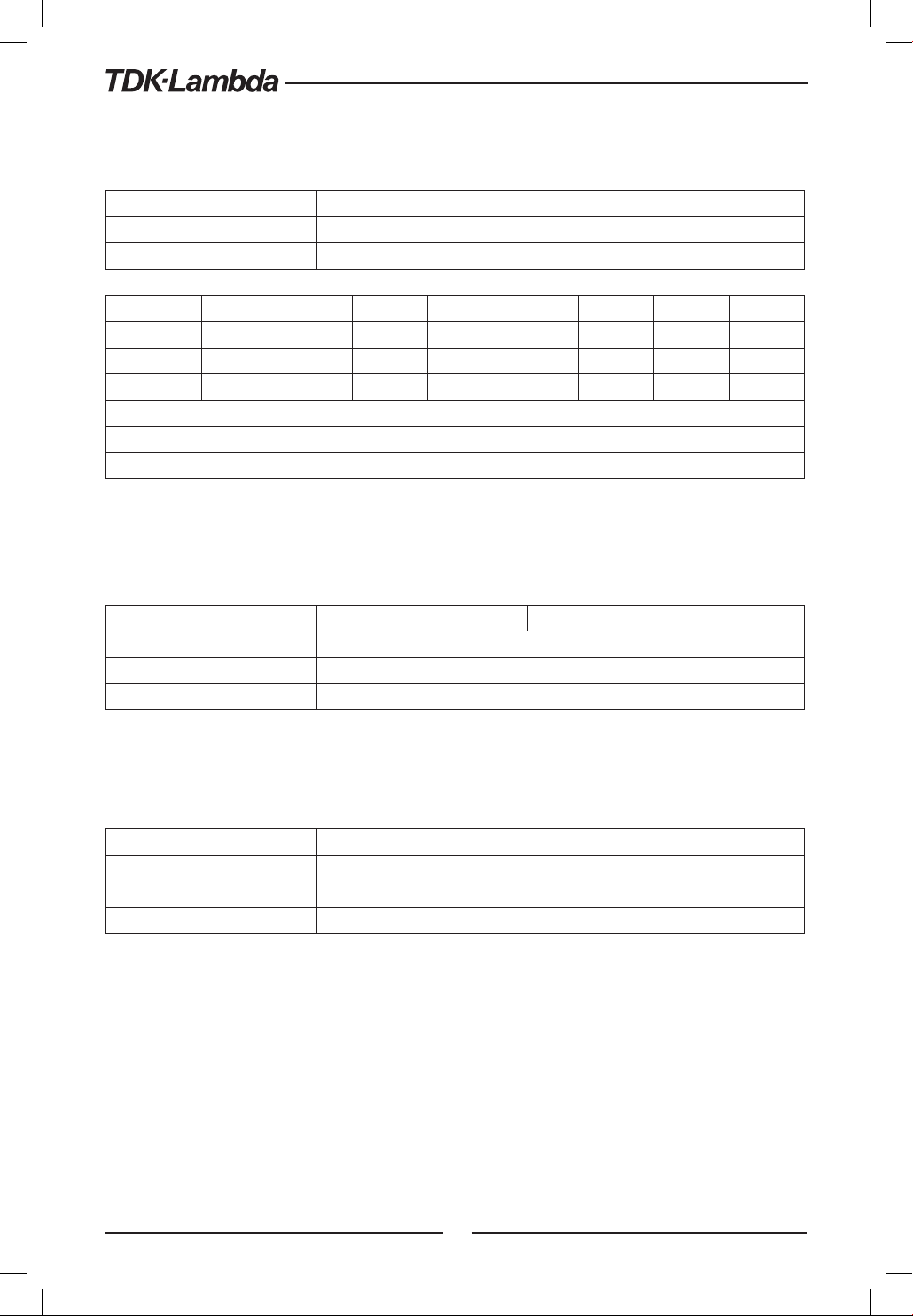
*STB?
Status Byte query. Returns the contents of the Status Byte Register.
Meaning and Type Status Byte Device Status
Query Syntax *STB?
Returned Parameters <NR1> (Register binary value)
Bit Position 7 6 5 4 3 2 1 0
Condition OPER MSS ESB MAV QUES 0 0 0
(RQS)
Bit Weight 128 64 32 16 8 4 2 1
ESB = Event status byte summary; MAV = Message available
MSS = Master status summary; OPER = Operation status summary;
QUES = Questionable status summary; RQS = Request for service
Table 7-11: Bit Configuration of Status Byte Register
*TRG
The Trigger command starts the waveform when the trigger source is set to BUS.
Meaning and Type Trigger Device Trigger
Command Syntax *TRG
Parameters None
Query Syntax None
ABORt
Resets the trigger system and places the power supply in an IDLE state without waiting for the
completion of the trigger cycle.
Command Syntax ABORt
Parameters None
Example ABOR
Query Syntax None
98
Page 99
7.12 SCPI Subsystem Commands
Subsystem commands are specific to power supply functions. They can be a single command
or a group of commands. Groups are comprised of commands that extend one or more levels
below the root.
Commands followed by a question mark (?) take only the query form. Except as noted in the syntax
descriptions, all other commands take both the command and query form.
7.12.1 Output Subsystem
OUTPut
This command enables or disables the power supply output. When output is turned off, voltage
display shows ”OFF”.
SCPI Command Syntax OUTPut[:STATe] <bool>
GEN Command Syntax OUT <bool>
Parameters 0|OFF 1|ON
*RST Value OFF
Examples OUTP 1 OUTP:STAT ON
Query Syntax OUTPut[:STATe]?
Returned Parameters 0|1
OUTPut:PON[:STATe]
• AUTO - The power supply output will return to its previous value when the latching fault
condition is removed or to the stored value after AC recycle.
• SAFE - The power supply output will remain Off after the fault condition is removed or after
AC recycle.
SCPI Command Syntax OUTPut:PON[:STATe] <bool>
GEN Command Syntax AST <bool>
Parameters 0|OFF 1|ON
*RST Value OFF
Examples OUTPut:PON 1
Query Syntax OUTPut:PON[:STATe]?
Returned Parameters 0|1
OUTPut:PROTection:CLEar
This command clears the latch that disables the output when an over voltage (OVP), under voltage
(UVP), or foldback (FOLD) fault condition is detected. All conditions that generate a fault must
be removed before the latch can be cleared. The output is then restored to the state before the
fault condition occurred.
SCPI Command Syntax OUTPut:PROTection:CLEar
GEN Command Syntax None
Parameters None
99
Page 100
OUTPut:PROTection:FOLDback
Foldback mode is used to disable the output when a transition is made between the operation
modes. The power supply will turn off the output after a specified delay if the power supply makes
transition into CV mode or into CC mode. This feature is particularly useful for protecting current
or voltage sensitive loads.
SCPI Command Syntax OUTPut:PROT:FOLDback[:MODE] <CRD>
GEN Command Syntax FLD <CRD>
Parameters OFF|0, CC|1, CV|2 .
*RST Value OFF
Examples OUTPut:PROT:FOLDback[:MODE] CC
Query Syntax OUTPut:PROT:FOLDback[:MODE]?
Returned Parameters <CRD>
OUTPut:PROTection:DELay
Sets the delay time between the programming of an output change that produces a CV or CC
status condition. This command applies to UVP and Foldback functions.
SCPI Command Syntax OUTPut:PROTection:DELay <NRf+>
GEN Command Syntax FBD
Parameters 0.1 to 25.5|MIN|MAX (step 0.1s)
Unit S (second)
*RST Value 0mS
Examples OUTPut:PROTection:DELay 2E-1
Query Syntax OUTPut:PROTection:DELay?
Returned Parameters <NR3>
OUTPut:ILC:MODE
Selects the mode of operation of the Remote Inhibit protection. In OFF mode the power supply
ignores J3-4 (ILC) status.
SCPI Command Syntax OUTPut:ILC:MODE <CRD>
GEN Command Syntax RIE
Parameters 0|OFF 1|ON
*RST Value OFF
Examples OUTPut:ILC:MODE ON
Query Syntax OUTPut:ILC:MODE?
Returned Parameters ON/OFF
100
 Loading...