

Page 1
(1/2)
Multilayer Chip Directional Couplers
For DCS/Tx
HHM Series HHM2209SA1
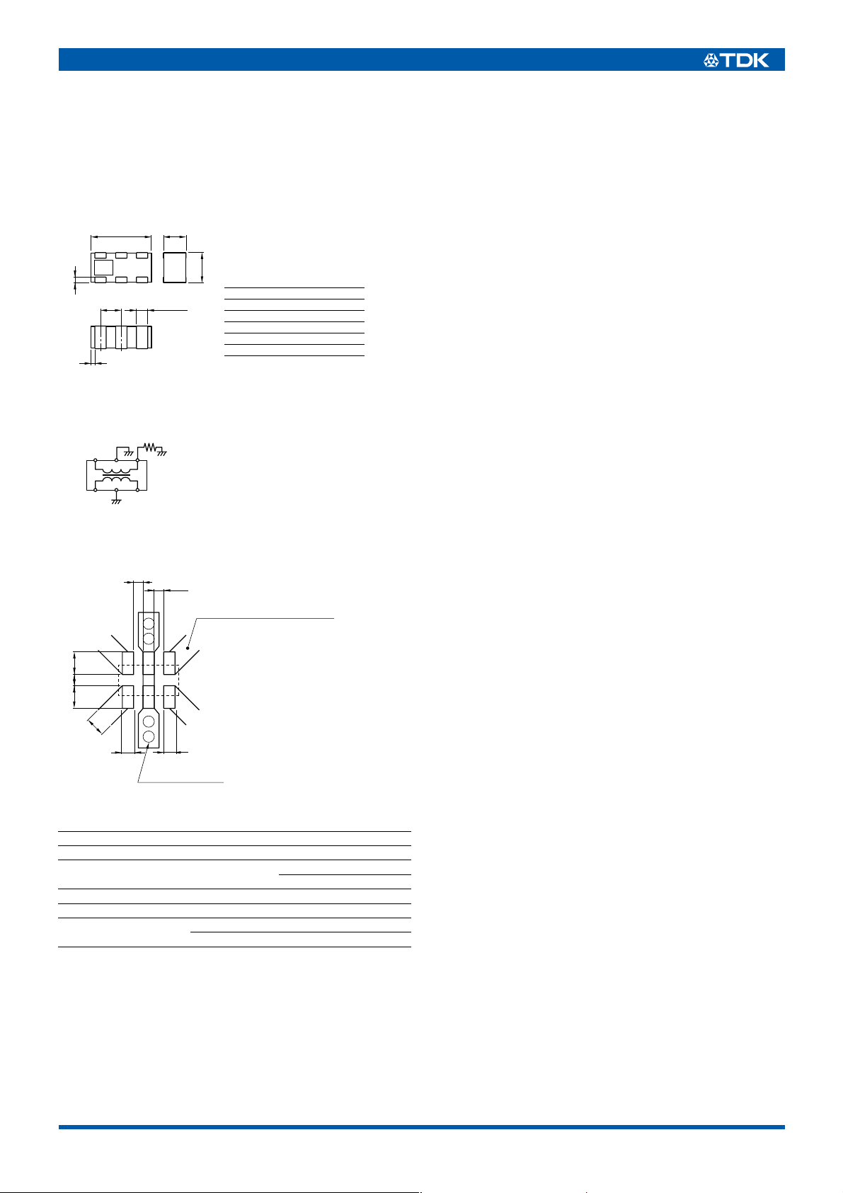
SHAPES AND DIMENSIONS
1.6± 0.1
654
123
0.15± 0.1
0.55± 0.1
0.1±0.1
CIRCUIT DIAGRAM
GND
Monitor
output
6
54
13
IN
GND
0.6± 0.1
0.8± 0.1
Terminal functions
0.3± 0.1
50
Ω
2
OUT
1 Input
2 GND
3 Output
450Ω load
5 GND
6 Monitor output
Dimensions in mm
Conformity to RoHS Directive
RECOMMENDED PC BOARD PATTERNS
0.25
0.25
This width is 50Ω.
Micro-strip line for 0.4mm thick
glass-epoxy substrate.
0.6
0.6 0.3
0.7
0.3
0.3
ø0.3 Through-hole
Dimensions in mm
ELECTRICAL CHARACTERISTICS
Frequency range 1710 to 1785MHz
Coupling factor –12.0±1.0dB
Insertion loss
Isolation 20dB min.
VSWR 1.3 max.
Temperature range
∗1
25°C
∗2
Operating temperature
Operating –40 to +85°C
Storage –40 to +85°C
0.55dB max.
0.60dB max.
∗1
∗2
• Conformity to RoHS Directive: This means that, in conformity with EU Directive 2002/95/EC, lead, cadmium, mercury, hexavalent chromium, and
specific bromine-based flame retardants, PBB and PBDE, have not been used, except for exempted applications.
• All specifications are subject to change without notice.
001-02 / 20080105 / e761_hhm2209sa1.fm
Page 2
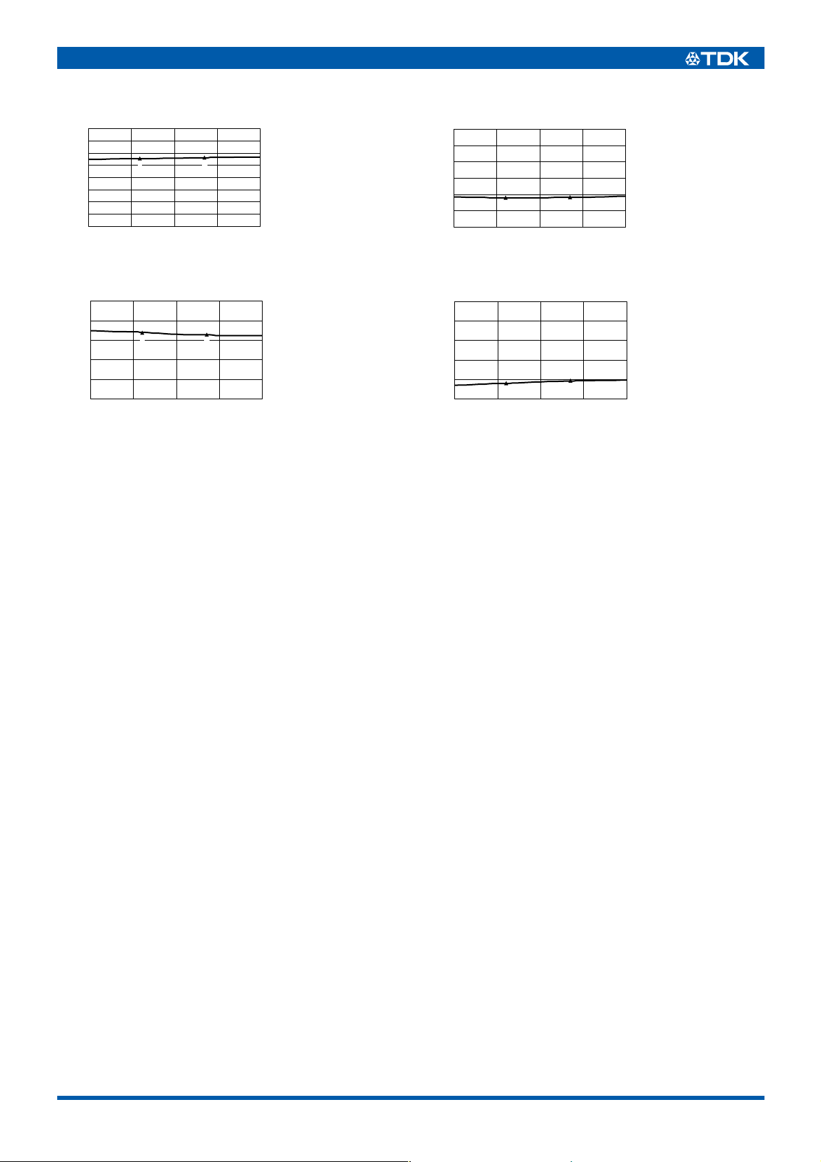
FREQUENCY CHARACTERISTICS
COUPLING
0
–5
)
dB
–10
(
–15
–20
–25
–30
Coupling factor
–35
–40
1650 1850180017501700
1
Frequency(MHz
2
)
1: 1710MHz
–12.3dB
2: 1785MHz
–11.9dB
ISOLATION
0
–10
)
–20
dB
(
–30
–40
Isolation
–50
–60
1650 1850180017501700
1
Frequency(MHz
(2/2)
1: 1710MHz
–42.0dB
2: 1785MHz
–41.9dB
2
)
INSERTION LOSS
0
)
–0.2
dB
(
–0.4
–0.6
–0.8
Insertion loss
–1
1650 1850180017501700
1
Frequency(MHz
VSWR
1: 1710MHz
–0.32dB
2: 1785MHz
2
)
–0.35dB
2.0
1.8
)
1.6
dB
(
1.4
VSWR
1.2
1.0
1650 1700 185018001750
1
Frequency(MHz
1: 1710MHz
1.16dB
2: 1785MHz
1.18dB
2
)
• All specifications are subject to change without notice.
001-02 / 20080105 / e761_hhm2209sa1.fm
 Loading...