

Page 1

Large Size Ferrite Cores for High Power
Summary
Issue date: November 2010
• All specifications are subject to change without notice.
• Conformity to RoHS Directive: This means that, in conformity with EU Directive 2002/95/EC, lead, cadmium, mercury, hexavalent chromium, and specific
bromine-based flame retardants, PBB and PBDE, have not been used, except for exempted applications.
Page 2
(1/7)
Large Size Ferrite Cores for High Power
Summary
Nowadays, more and more high-frequency circuits are being used in industrial equipment as well as consumer equipment. With the use of
higher frequencies, silicon steel sheets have become unsuitable for magnetic material used in transformers. Ferrite, its substitute, delivers
reduced core loss at high frequencies and is the optimum material for high-power requirements.
To meet these various demands, we at TDK have employed our ferrite development technologies accumulated over the years and
advanced production technologies to offer large, high-quality cores for high-frequency, high-power power supplies.
In the following information, introduce ferrite cores that used PE22, PC40 and PE90 materials having superior magnetic characteristics.
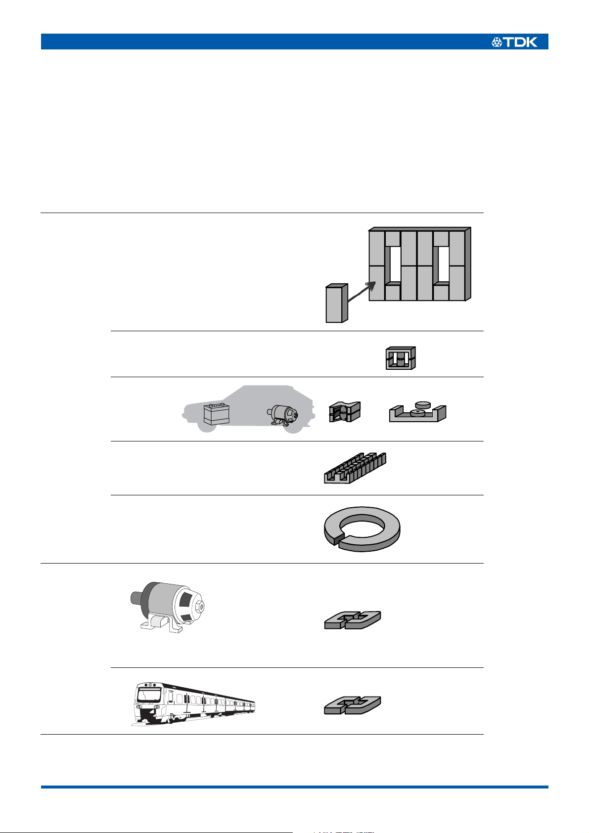
APPLICATIONS
High frequency inductive heater EE320x250x20
Transformer
Reactor choke
Uninterruptible Power Supply System(UPS)
CATV’s power supply
Photovoltaic power generation
Power supply of communications station
Electrical vehicle
Automated warehouse, conveyor machine
Current sensor
General purpose inverter • Air conditioner
• Fun
• Pump
• Printing press
• Packing machine
• Machines for food industry
• Drier
• Compressor of freezer
• Textile machine
• Woodworking machine
• Medical machine
Trains
EC70,90,120
PQ78,107
UU79x129x31
UU79x129x31
• All specifications are subject to change without notice.
003-02 / 20101108 / e16_1.fm
Page 3
FEATURES
• Large size ferrite cores developed for reactors and transformers used in high power units.
• Please contact us for machinability of non-standard special forms.
MATERIAL CHARACTERISTICS (Typical)
Material PE22 PC40 PE90
Initial permeability µi [23°C] 1800 2300 2200
Curie temperature Tc °C >200 >200 >250
Saturation magnetic flux density
H=1194A/m
Remanent flux density Br [23°C] mT 140 125 170
Coercive force Hc [23°C]A/m161513
Core loss
25kHz, 200mT
100kHz, 200mT 520 420 400
Electrical resistivity ρΩ • m 3.0 6.5 6.0
Approximate density dapp kg/m
Thermal expansion coefficient α 1/K 12×10
Thermal conductivity κ W/mK555
Specific heat C
Bending strength δ
Young’s modulus E N/m
Magnetostriction λs –0.6×10
• 1(mT)=10(G),1(A/m)=0.012566(Oe)
[23°C]
Bs
[100°C]
mT
[90°C]
Pcv
[100°C]
p J/kg • K 600 600 600
b3 N/m
kW/m
510
410
79 64 60
3
80 70 68
3
2
2
4.8×10
9×10
1.2×10
3
–6
7
11
–6
500
380
4.8×10
12×10
7
9×10
1.2×10
–0.6×10
3
–6
11
–6
530
430
4.9×10
12×10
7
9×10
1.2×10
–0.6×10
3
–6
11
–6
(2/7)
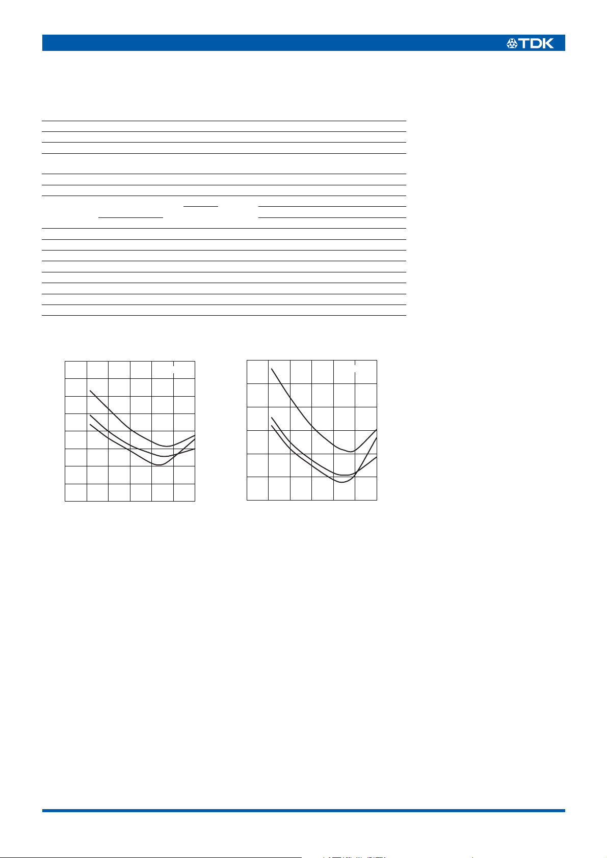
CORE LOSS vs. TEMPERATURE CHARACTERISTICS
200
150
)
3
100
kW/m
(
cv
P
25kHz-200mT
PE22
PC40
PE90
50
0
Temperature(˚C
)
120100806040200
900
700
)
3
kW/m
(
cv
P
500
300
PE22
PC40
PE90
Temperature(˚C
100kHz-200mT
)
120100806040200
• All specifications are subject to change without notice.
003-02 / 20101108 / e16_1.fm
Page 4

CORE LOSS vs. FREQUENCY CHARACTERISTICS
MATERIAL:PE22
10000
Material : PE22
Temp.23˚C
10000
Material : PE22
Temp.40˚C
(3/7)
1000
)
3
100
(kW/m
cv
P
10
1
10 100 1000 10000
Frequency (kHz)
10000
Material : PE22
Temp.60˚C
1000
)
3
100
(kW/m
cv
P
10
1
10 100 1000 10000
Frequency (kHz)
50mT
100mT
150mT
200mT
250mT
300mT
50mT
100mT
150mT
200mT
250mT
300mT
1000
)
3
100
(kW/m
cv
P
10
1
10 100 1000 10000
Frequency (kHz)
10000
Material : PE22
Temp.80˚C
1000
)
3
100
(kW/m
cv
P
10
1
10 100 1000 10000
Frequency (kHz)
50mT
100mT
150mT
200mT
250mT
300mT
50mT
100mT
150mT
200mT
250mT
300mT
10000
Material : PE22
Temp.90˚C
1000
)
3
100
(kW/m
cv
P
10
1
10 100 1000 10000
Frequency (kHz)
10000
Material : PE22
Temp.120˚C
1000
)
3
100
(kW/m
cv
P
10
1
10 100 1000 10000
Frequency (kHz)
50mT
100mT
150mT
200mT
250mT
300mT
50mT
100mT
150mT
200mT
250mT
300mT
10000
Material : PE22
Temp.100˚C
1000
)
3
100
(kW/m
cv
P
10
1
10 100 1000 10000
Frequency (kHz)
50mT
100mT
150mT
200mT
250mT
300mT
• All specifications are subject to change without notice.
003-02 / 20101108 / e16_1.fm
Page 5

MATERIAL:PC40
10000
Material : PC40
Temp.23˚C
10000
Material : PC40
Temp.40˚C
(4/7)
1000
)
3
100
(kW/m
cv
P
10
1
10 100 1000 10000
Frequency (kHz)
10000
Material : PC40
Temp.60˚C
1000
)
3
100
(kW/m
cv
P
10
1
10 100 1000 10000
Frequency (kHz)
50mT
100mT
150mT
200mT
250mT
300mT
50mT
100mT
150mT
200mT
250mT
300mT
1000
)
3
100
(kW/m
cv
P
10
1
10 100 1000 10000
Frequency (kHz)
10000
Material : PC40
Temp.80˚C
1000
)
3
100
(kW/m
cv
P
10
1
10 100 1000 10000
Frequency (kHz)
50mT
100mT
150mT
200mT
250mT
300mT
50mT
100mT
150mT
200mT
250mT
300mT
10000
Material : PC40
Temp.90˚C
1000
)
3
100
(kW/m
cv
P
10
1
10 100 1000 10000
Frequency (kHz)
10000
Material : PC40
Temp.120˚C
1000
)
3
100
(kW/m
cv
P
10
1
10 100 1000 10000
Frequency (kHz)
50mT
100mT
150mT
200mT
250mT
300mT
50mT
100mT
150mT
200mT
250mT
300mT
10000
Material : PC40
Temp.100˚C
1000
)
3
100
(kW/m
cv
P
10
1
10 100 1000 10000
Frequency (kHz)
50mT
100mT
150mT
200mT
250mT
300mT
• All specifications are subject to change without notice.
003-02 / 20101108 / e16_1.fm
Page 6

MATERIAL:PE90
10000
Material : PE90
Temp.23˚C
10000
Material : PE90
Temp.40˚C
(5/7)
1000
)
3
100
(kW/m
cv
P
10
1
10 100 1000 10000
Frequency (kHz)
10000
Material : PE90
Temp.60˚C
1000
)
3
100
(kW/m
cv
P
10
1
10 100 1000 10000
Frequency (kHz)
50mT
100mT
150mT
200mT
250mT
300mT
50mT
100mT
150mT
200mT
250mT
300mT
1000
)
3
100
(kW/m
cv
P
10
1
10 100 1000 10000
Frequency (kHz)
10000
Material : PE90
Temp.80˚C
1000
)
3
100
(kW/m
cv
P
10
1
10 100 1000 10000
Frequency (kHz)
50mT
100mT
150mT
200mT
250mT
300mT
50mT
100mT
150mT
200mT
250mT
300mT
10000
Material : PE90
Temp.90˚C
1000
)
3
100
(kW/m
cv
P
10
1
10 100 1000 10000
Frequency (kHz)
10000
Material : PE90
Temp.120˚C
1000
)
3
100
(kW/m
cv
P
10
1
10 100 1000 10000
Frequency (kHz)
50mT
100mT
150mT
200mT
250mT
300mT
50mT
100mT
150mT
200mT
250mT
300mT
10000
Material : PE90
Temp.100˚C
1000
)
3
100
(kW/m
cv
P
10
1
10 100 1000 10000
Frequency (kHz)
50mT
100mT
150mT
200mT
250mT
300mT
• All specifications are subject to change without notice.
003-02 / 20101108 / e16_1.fm
Page 7

SATURATION MAGNETIC FLUX INITIAL MAGNETIC PERMEABILITY vs.
DENSITY vs. TEMPERATURE TEMPERATURE CHARACTERISTICS
CHARACTERISTICS
700
600
PE22
500
)
400
mT
(
s
B
300
200
100
0
PC40
Temperature(˚C
PE90
)
150100500
µ
i
5000
4000
3000
2000
1000
f=1kHz
Hm=0.4A/m
0
PC40
PE22
PE90
Temperature(˚C
)
3002001000
AMPLITUDE PERMEABILITY vs. SATURATION MAGNETIC FLUX DENSITY CHARACTERISTICS
7000
6000
Material : PE22
f=16kHz
7000
6000
Material : PC40
f=16kHz
7000
6000
Material : PE90
f=16kHz
(6/7)
5000
a
µ
4000
120˚C
100˚C
80˚C
60˚C
3000
40˚C
23˚C
2000
0 100 200 300
Flux density(mT
)
5000
a
µ
120˚C
4000
100˚C
80˚C
60˚C
40˚C
3000
23˚C
2000
0 100 200 300
Flux density(mT
MAGNETIC PERMEABILITY vs. FREQUENCY CHARACTERISTICS
µ′, µ′′
4000
3000
2000
1000
Material: PE22
Temp.: 23
Hm=0.4A/m
0
˚C
µ′
Frequency(kHz
µ′′
)
1000010 100 1000
µ′, µ′′
4000
3000
2000
1000
Material: PC40
Temp.: 23
Hm=0.4A/m
0
˚C
µ′
Frequency(kHz
5000
80˚C
60˚C
a
40˚C
µ
100˚C
4000
23˚C
120˚C
3000
2000
)
0 100 200 300
4000
Material: PE90
Temp.: 23
Hm=0.4A/m
3000
Flux density(mT
˚C
)
µ′
µ′′
2000
,
µ′
µ′′
1000
µ′′
)
1000010 100 1000
0
Frequency(kHz
)
1000010 100 1000
• All specifications are subject to change without notice.
003-02 / 20101108 / e16_1.fm
Page 8

(7/7)
DIMENSIONAL RESONANCE
Dimensional resonance is a phenomenon which increases loss
and decreases magnetic permeability by electromagnetic standing
waves when the magnetic field of the core frequency is applied.
The phenomenon appears when the maximum dimension of the
cross section of the core perpendicular to the magnetic field is the
integral multiple of about half of the electromagnetic wavelength
C
λ=
f ×
µrεr×
C: Electromagnetic wave speed in a vacuum(3.0×10⁸m/s)
r: Relative magnetic permeability
µ
r: Relative permissivity
ε
f: Frequency of the applied magnetic field(electromagnetic wave)
As µe decreases by inserting into the gap, using the same core
enables high frequency wave usage as indicated by the formula
above.
As dimensional resonance quickly decreases magnetic permeability, design the actual frequency to avoid dimensional resonance.
In the case of possible dimensional resonance, it can be protected
against by dividing the core in the magnetic circuit direction and
bonding them.
RESONANCE DIMENSION vs. FREQUENCY
CHARACTERISTICS
3
10
)
mm
(
2
10
Resonant dimension
1
10
10
PE22
PC40
1
2
10
Frequency(kHz
)
3
10
GENERAL PRECAUTIONS WHEN USING FERRITE CORE
• When selecting the material/form of the ferrite core, while
considering the margins select from the range in the catalog
(product manual) display where factors such as inductance
value, maximum saturation flux density, core loss, temperature
characteristics, frequency characteristics and Curie temperature
λ.
are concerned.
• Select material that does not corrode or react in order to avoid
insulation failure or a layer short, and also be careful to avoid
loose winding of the core or causing damage to the wire.
• Be careful that the equipment and tools you use do not strike the
core in order to avoid core cracks.
• Please consider using cases, bobbins or tape for insulation
purposes.
• When using cases and bobbins, select those with a heat
expansion coefficient as close to that of the ferrite as possible.
• When laying out the case, bobbin, coil and the ferrite core,
create clearance between each part in order to prevent any core
cracks and to assure insulation.
• Please handle with care, since a ferrite core is susceptible to
shock.
• The outward appearance is determined according to the
standard of our company.
• Do not place close to strong magnets.
• Be careful not to cause shock by the use of equipment and tools.
• Be careful not to expose to rapid change in temperature, since it
is also susceptible to thermal shock.
• Careless handling may hurt your skin, since the corners of the
polished surface of the ferrite are very sharp, and in some
cases, burrs may have formed on the surface.
• Please be very careful when stacking and handling the
containers, since some ferrite cores are heavy, and can cause
injury, toppling or back pain.
• Where inner packaging is concerned, please be careful not to
damage the core when taking it out from the container since the
packing materials used in order to prevent damage during
transportation may make it difficult to take out.
• Do not reprocess the ferrite core as it can cause problems, such
as injury.
• All specifications are subject to change without notice.
003-02 / 20101108 / e16_1.fm
 Loading...