


Publication T1-721, Revision 3
CALL MURCAL TO PLACE YOUR ORDER
Dated: April 15, 2006
INSTALLATION AND OPERATING
MANUAL
TURBOTWIN Engine Air Starters
From
Tech Development
MODEL: T100-V
P:(661)272-4700 F:(661)947-7570
www.murcal.com
e-mail: sales@murcal.com
M
ur
AN 98-440
al
C
c

TDI TURBOTWIN™
FROM TECH DEVELOPMENT
TABLE OF CONTENTS
SECTION SUBJECT PAGE
1.0 General Information 1
2.0 Orientation of the Starter 2
3.0 Installing the Starter 2
4.0 Starter Operation 4
5.0 T100-V Warranty 6
6.0 Troubleshooting Guide 7
LIST OF ILLUSTRATIONS
FIGURE TITLE PAGE
1 Direction of Rotation 2
2 T100-V with Exhaust Guard 8
3 T100-V with Exhaust Elbow 9
4 T100-V Installation Drawing 10
5 T100-V Multiple Starter Drawing 11
Performance Curves 12
Issued April 15, 2006
Page: i
Publication T1-721, Rev. 3

TDI TURBOTWIN™
FROM TECH DEVELOPMENT
1.0 GENERAL INFORMATION
This manual provides instructions for the installation and
operation of the TDI T100-V T
there are questions not answered in this manual, please
contact your TDI T
assistance.
The T100-V starters are turbine driven starters with a
pre-engaged starter drive. The T100-V starters have
applications ranging from 1800 CID (30 Liters) on diesel
engines and up to 18000 CID (300 Liters) on gas
engines. The T100-V models are suited to operate within
a wide range of inlet pressures and ambient
temperatures. The engine size and parasitic loading will
determine the exact minimum pressure that will assure
reliable cranking.
The T100-V starters are designed for operation with
compressed air or natural gas; materials used are
compatible with “sour” natural gas and marine
environments. Small amounts of foreign matter or liquid
in the air supply will not adversely affect T100-V starters.
As with all TDI starters, no lubrication is required in the
air supply.
Please review the rest of this manual before installing
the T100-V air starter.
WARNINGS, CAUTIONS, AND NOTES
Certain types of information are highlighted in this
manual for your attention:
WARNING - used where injury to personnel or
damage to the equipment is possible.
CAUTION - used where there is the possibility of
damage to the equipment.
NOTE - used to point out special interest
information.
Throughout this manual, the term “air” is used to
designate the starter drive medium. Unless otherwise
stated, “air” means either compressed air or natural gas.
URBOTWIN distributor or dealer for
URBOTWIN Air Starters. If
NOTE
1.1 DESCRIPTION
The T100-V features three basic subassemblies: a
unique two stage turbine motor section, an offset/spur
gear assembly and a pre-engage drive assembly.
The two stage motor section features greater stall torque
than a single stage turbine plus aerodynamic speed
control. This aerodynamic speed control helps protect
the T100-V starter from damage caused by starter motor
over speed. In addition, a specially designed motor
housing module and low-mass rotors provide fail-safe
operation.
The T100-V employs 9.25:1 ratio spur gearbox. This low
gear ratio allows the turbine motor to spin at low speeds
for long bearing life. At a typical 3000 rpm pinion speed,
the turbine is rotating at a low 27750 rpm.
A reliable pre-engaged drive delivers the torque to the
pinion. The pinion is translated out to engage the
engine's ring gear via the starter’s engagement piston.
Compressed air or natural gas is used to power the
T100-V through the inlet port. The air or gas is expanded
through the first nozzle or stators. The high velocity gas
impinges on the first stage rotor to yield torque to the
gearbox through momentum exchange. The gas is
further directed through the second stage stators which
impart additional torque to the second stage rotor.
1.2 PRODUCT IDENTIFICATION
The starter nameplate which is attached to the turbine
housing contains the following information: model
number, serial number, part number, direction of rotation
and the maximum rated operating pressure.
The directions of rotation are either right hand or left
hand rotation as shown in Figure 1. Right Hand rotation
is defined as clockwise rotation as viewed from the
pinion end of the starter, and Left Hand rotation is
counter clockwise rotation viewed from the pinion end of
the starter.
Publication T1-721, Rev. 3 Page 1
Issued April 15, 2006

TDI TURBOTWIN™
FROM
The maximum operating pressure identified on the
nameplate is measured at the check port on the starter
inlet with the starter in operation.
Exceeding the maximum pressure shown on the
nameplate may result in drive failure, damage to the
starter, or damage to the engine.
The housing proof pressure is 600 psig and is also
shown on the nameplate. This means that the turbine
housing will not burst when subjected to a static
pressure of 600 psig.
1.3 PHYSICAL CHARACTERISTICS
Figure 2 shows the standard configuration for the T100V with exhaust screen. This model weighs
approximately 54 lbs. and is 16.8 inches in length. The
turbine housing diameter is 6.8 inches, which is common
to all T100 T
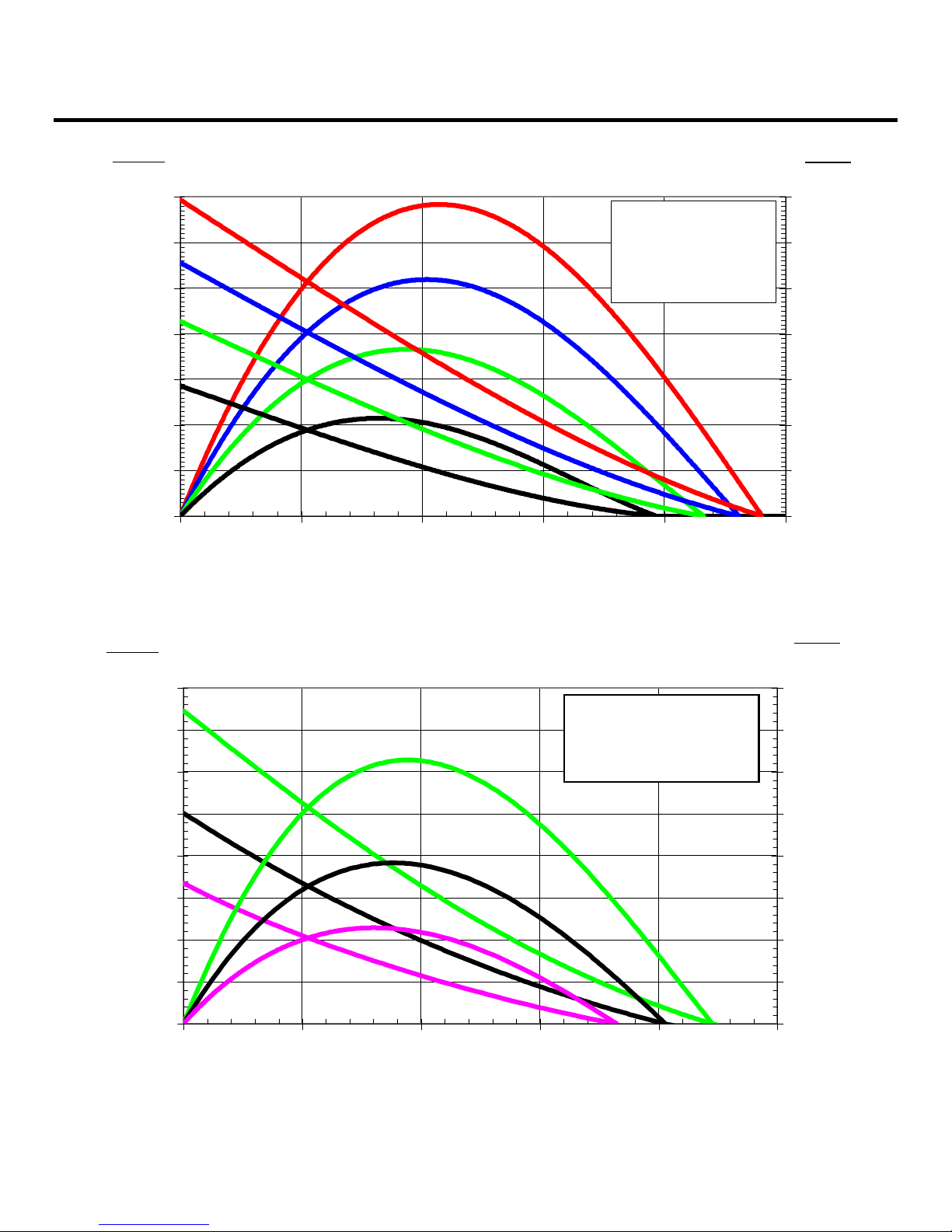
1.4 PERFORMANCE
The performance curve for the T100-V illustrates the
pinion torque versus pinion speed (rpm) at a constant
drive air pressure, and horsepower versus pinion
speed at a constant drive air pressure. The pinion
speed is shown on the horizontal axis while the pinion
torque is shown on the left edge of the vertical axis. Air
consumption rates are given for the various drive
pressures. The drive gas used for the performance
curve is air.
TECH DEVELOPMENT
Figure 1. Direction of Rotation viewed from Pinion End.
CAUTION
URBOTWIN air starters.
2.0 ORIENTATION OF THE STARTER
If the factory orientation of the starter turbine housing
assembly does not fit your engine installation, this
component can be re-oriented.
Determine the required orientation of the turbine housing
assembly and gearbox housing assembly. The turbine
housing assembly can be rotated to six different
positions relative to the gearbox housing assembly. The
drive assembly can be rotated to twenty four positions
relative to the inlet port.
Orientation of the starter should be accomplished prior to
installing the starter on the engine.
CAUTION
All screw threads are treated at the factory with a
fastener retention compound. Every screw and tapped
hole must be clean and have a drop of Loctite 242
applied to the threads before being installed.
3.0 INSTALLING THE STARTER
A turbine air starter does not require lubrication in the
supply air. Therefore, if a vane type starter motor is
being replaced, TDI recommends that all lubrication
devices and lines be removed to minimize flow
restrictions.
WARNING
If a fuel (pulse) lubricator has previously been installed in
the system, disconnect and plug the line to eliminate
spraying diesel fuel on the engine.
The starter should be installed with the inlet valve in a
position between horizontal and straight down. Any
condensation will be restricted to the air lines and not in
the starter.
WARNING
Do not operate this starter unless it is properly
connected to an engine.
3.1 SUPPLY LINE INSTALLATION
WARNING
Be sure to either bleed the pressurized air reservoir
and/or safety the system such as closing all valves prior
to installing any starter supply line.
Page 2 Publication T1-721, Rev. 3
Issued April 15, 2006

TDI TURBOTWIN™
FROM TECH DEVELOPMENT
T100-V starters come standard with a 2" NPT female
pipe thread for the inlet connection port. The supply line
consists of the line from the air source, a pressure
regulator (when necessary), a manual or relay valve,
and the connection to the starter inlet. Hard piping may
be used, but a section of flexible tubing should be
installed at the starter to prevent leaks due to engine
vibration.
Care must be taken to ensure that all inlet supply line
piping is no less than 1.5” and that all components used
are capable of passing the required air flow.
NOTE
Valves with a Cv of 40 or higher are recommended.
If the supply line must be longer than 20 feet, the inlet
supply line piping should be increased to 2" in diameter
to ensure proper performance by your T
Because turbine starters such as the T100-V are
sensitive to flow restrictions, care must be taken to use
uniform hose or tubing and fittings for connection of the
supply line. Tees, elbows and line length must be kept
to a minimum. TDI recommends that hose or flex
couplings be installed to eliminate possible leakage
caused by strain on the supply line.
Normally, an air strainer is not required. In dirty
environments, use of a #40 mesh Y-strainer is
recommended. The T100-V is highly tolerant of dirt in
the air line, however, starter life can be increased with
the use of an air strainer.
A pressure regulator is required when the air supply
pressure is great enough to exceed the starter operating
pressure (at the inlet port) and/or the maximum torque.
A manual ball valve may be used to admit drive air/gas
to the starter. The manual valve should be located in a
safe position away from the engine.
A preferred valve is pilot-operated, which can be
pneumatically or electrically actuated. The valve should
be located close to or even on the starter inlet for best
performance. Pneumatic or electrical control lines may
be routed virtually anywhere for the customer's preferred
operating station. This type of valve actuates from a fully
closed to a fully open position very rapidly. TDI offers a
variety of relay valves such as P/N RLVA-25683-001-201, which is a 1-1/2" port, pneumatically actuated valve.
The supply line should be dry-fitted for proper
alignment/location prior to final assembly. All pipe-
URBOTWIN.
threaded joints should be sealed with Loctite Pipe
Thread Sealant (TDI P/N 9-94085) or equivalent for leak
tight joints prior to final assembly. Be sure to tighten all
joints to proper torque after final assembly.
CAUTION
In cold weather climates, care should be taken while
designing your installation to prevent condensation from
developing in the starter system. In systems with a
regulator valve or relay valve, there is the possibility of
freeze-ups.
A tee connection with a quick disconnect can be added
to the inlet. This will allow an external air source to be
used to accomplish a “blow start” if the system freezes.
Once the engine has been started, the other system
components may be thawed.
CAUTION
On new installations, it is strongly recommended to blow
out the supply line with air to remove possible dirt and
welding slag prior to final connection to the TURBOTWIN
starter. Be sure to secure the free end of the supply line
prior to blowing out the line.
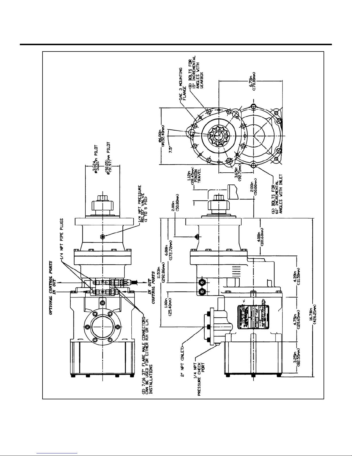
3.2 INLET PRESSURE PORT
A 1/4" NPT port is located on the air inlet. This port may
be used to check the supply pressure at the starter when
the starter is operating. Remove the 1/4" NPT pipe plug
and save for later use. Install 1/4" minimum size tubing
to the port. Route the tubing away from the starter to a
safe location away from the engine. Install a pressure
gauge on the tubing. This pressure monitoring
line/gauge may be permanently installed. Use Loctite
Pipe Thread Sealant or equivalent. Alternately, a
pressure transducer may be installed at the pressure
check port and electrical lines routed to a digital display
at the operator's station.
This pressure port is invaluable in diagnosing air starter
and/or installation problems.
3.3 EXHAUST PIPING
The turbine exhaust may be plumbed away from the
starter area. All starters using natural gas must be piped
according to industry codes and local regulations.
The performance of a turbine starter will be decreased
because of back pressure when smaller than
recommended exhaust piping is installed. If back
pressure hampers starter performance, compensation
Publication T1-721, Rev. 3 Page 3
Issued April 15, 2006

TDI TURBOTWIN™
FROM
can be made by increasing the supply pressure. Consult
your TDI distributor for advice.
Exhaust piping should be routed downward to help
prevent any accumulation of condensation in the starter
motor.
If the overhung section of the starter is not otherwise
supported, TDI recommends that the exhaust piping be
supported with a suitable bracket(s).
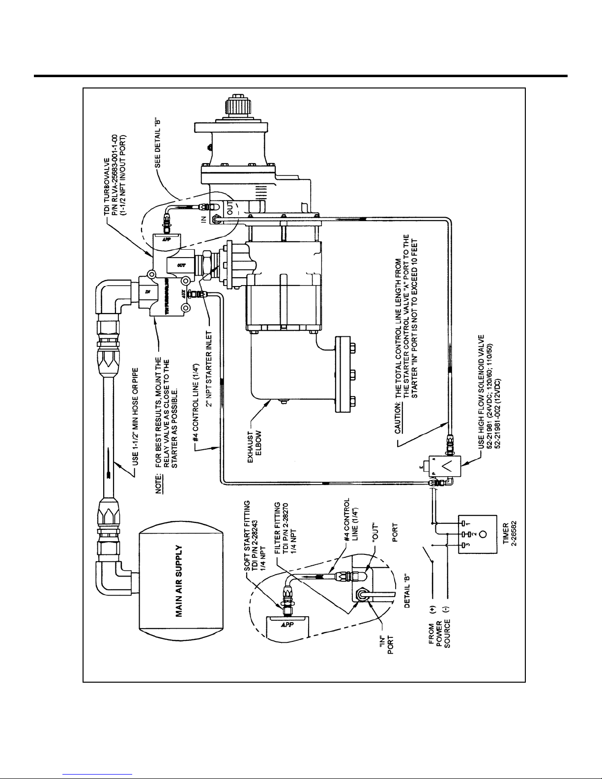
3.4 SOFT START VALVE & FILTER FITTING
The “soft start” fitting (P/N: 2-28243), by providing a
slower opening of the starter relay valve, eliminates
excessive starter pinion gear loading. The soft start
fitting is identified by the mark “EL-SOFT START” found
on its body. This fitting MUST be installed at the starter
relay valve as shown in figure 4. It is screwed into the
applied pressure (“IN” or “APP”) port on the starter relay
valve. There are currently no approved substitutions for
this fitting.
The filter fitting (P/N: 2-28270) provides contamination
protection to the starter’s pre-engagement mechanism
and the soft start fitting installed downstream. The filter
fitting is to be installed on the “IN” port of the starter as
shown in figure 4. It appears similar to the soft start
fitting, however, there are no identifying marks on the
filter fitting.
For multiple starter applications, a soft start fitting must
be installed on EACH relay valve and a filter fitting must
be installed on EACH starter as shown in figure 5.
CAUTION
For maximum pinion life and full warranty coverage,
the soft start valve (P/N: 2-28243) MUST be installed
in the applied pressure port (APP) of the relay valve.
3.5 NATURAL GAS INSTALLATION
The installation of the starter using natural gas is similar
to the air installation except all fittings, piping, valves and
regulators must be compatible with natural gas.
Proper control of natural gas is a major consideration
when used in the starter system. All starters using
natural gas must pipe the exhaust according to industry
codes and local regulations.
There is a natural gas vent port in the turbine housing
that is plugged for compressed air use. This vent is used
to remove any natural gas that could leak past the
TECH DEVELOPMENT
primary turbine shaft seal. Remove this 3/8"NPT plug
and install a line to carry gas away from the starter area.
WARNING
Do not connect the turbine housing vent line to the
turbine exhaust line. Exhaust gas can pressurize the
turbine housing.
3.6 PIPING SYSTEM
Only type approved metallic hose assemblies are
approved in permanently pressurized compressed air
lines of starters. Non-metallic hose assemblies are
allowed only in case the piping system will be emptied
after the starting procedure.
Pipe unions must be type approved by GL. Downstream
of the pressure regulator a pressure relief valve is to be
provided.
4.0 STARTER OPERATION
Prior to operation, check that all connections are tight
and free from leaks. Check the 1/4" NPT pipe plug or a
pressure gauge/transducer that may be connected to the
pressure port on the starter inlet.
WARNING
Do not operate the TDI T
pressure greater than the pressure rating on the
nameplate. This pressure is measured at the starter
inlet while the starter is running.
The maximum operating pressure limit is the inlet
pressure measured at the starter’s inlet pressure check
port. In order to check the starter, a 1/4"NPT pipe tap
connection is provided in the inlet housing to attach a
pressure gauge/transducer). The maximum pressure
assumes an open exhaust (the standard turbine exhaust
guard). The standard exhaust guard causes no back
pressure.
The static non-flowing supply pressure will always be
higher than the operating (dynamic) pressure. The
maximum pressure limit (proof pressure) that the T100-V
starter housings may be subjected to is 600 PSIG (42
BAR). System pressure that exceeds the maximum
operating limit must use a pressure reducing device to
ensure that the operating pressure limit to the T100-V
starter is maintained.
System static pressure that exceeds the 600 PSIG (42
BAR) limit must, in addition to pressure reducer devices,
URBOTWIN starter with air
Page 4 Publication T1-721, Rev. 3
Issued April 15, 2006

TDI TURBOTWIN™
FROM TECH DEVELOPMENT
incorporate a pressure relief valve set below 600 PSIG
(42 BAR) in the supply air line.
NOTE
For maximum life of the starter pinion and for the
protection of the engine ring gear, limit the operating
pressure to that necessary to start the engine at its most
difficult starting conditions.
All appropriate local pressure codes and pressure
limitations on other system components must be
adhered to and supersede the guidelines given in this
manual.
Consult your TDI distributor if you have exhaust
plumbing that creates back pressure and reduces starter
performance. You may be able to increase the supply
pressure to restore the lost power.
Follow the engine manufacturer’s instructions for starting
the engine.
CAUTION
The grease used in the planetary system has a shelf life
of 2 years. Therefore, if the starter is NOT installed and
operated on the engine for 2 years after the starter is
manufactured, the grease should be replaced prior to
starter operation. The manufactured date is reflected in
the starter serial number. (Ex: 0602-0567 has a
manufactured date of February 2006).
4.1 BASIC OPERATION
The basic operation of the starter follows:
Pressurized air or natural gas is admitted to the starter’s
engagement piston chamber via the “in” control port by
opening the manual or solenoid valve. The air then
translates the starter’s piston forward allowing the pinion
to engage the engine’s ring gear.
The forward movement of the piston causes the starter’s
“out” control port to open. Air is then transmitted to the
automatic pilot port (APP) on the relay valve causing the
relay valve to open.
Pressurized air or natural gas is admitted to the starter’s
turbine assembly by the opening of the relay valve. The
air expands through the turbine which produces shaft
rotation and torque. The starter motor torque causes the
engine to accelerate. The fuel and ignition systems now
fire the engine. Closing the relay valve stops the starter.
The operator may decrease starter life by the continual
operation of the starter after the engine has started.
Upon a successful engine start, turn the air off to the
starter immediately. Minimizing the time the starter is
operating unloaded (i.e. the engine is running) will
maximize starter life. If a start is aborted, a restart may
be attempted after the engine and the starter has come
to rest.
CAUTION
Do not engage the starter while the engine is running.
The drive air pressure is the primary starter control
parameter. It is important, especially on new
installations, to measure this pressure during several
engine starts. The secondary parameter is the starter
pinion speed. This speed is usually measured by
knowledge of the engine starting speed and the starter
cranking ratio. The cranking ratio is the number of ring
gear teeth divided by the number of pinion teeth. The
starter pinion speed is then found by multiplying the
engine speed by the cranking ratio. The pinion speed is
usually 2000-3500 rpm at typical engine starting speed.
4.2 AUTOMATED START PANEL
The starter drive pressure measured at the starter inlet
will need to be set. As noted above, for maximum life of
the starter pinion and for the protection of the engine ring
gear, limit the operating pressure to that necessary to
start the engine at its most difficult starting conditions.
The speed control parameter will then need to be set.
Engine starting speed along with the cranking ratio
number can be used to determine starter pinion speed.
The pinion speed is usually 2000-3500 rpm for a typical
engine starting speed. Once the start sequence has
begun, the air is admitted to the starter. The starter
begins to accelerate the engine. Once the firing speed of
the engine is reached, the automated start panel may
deliver fuel to the engine. The engine will begin to
accelerate under its own power. The starter should be
dropped out of the sequence at a rpm higher than the
firing speed, but less than the engine idle speed.
The automated start panel should monitor engine speed
to determine air on and air off. Do not simply use time
as a control parameter. Avoiding excessive operation of
the starter after the engine is firing will maximize the
starter life.
Publication T1-721, Rev. 3 Page 5
Issued April 15, 2006

TDI TURBOTWIN™
FROM
5.0 WARRANTY
TDI TURBOTWIN ENGINE STARTER WARRANTY
Tech Development Inc. (TDI) warrants to the original user of the TDI TURBOTWIN™ Model T100-V Series air starters to
be free from defects in material and workmanship for a period of one year from the date of installation. The warranty
period shall not extend beyond two years from the date the unit was manufactured. (i.e.: a unit with a manufactured date
of July 1999 (SN: 9907-101) will not be covered under warranty after July 2001). The conditions of this warranty are: a)
TDI is notified within this period by return of such product to TDI or its authorized distributor/dealer, transportation prepaid
by user; b) the starter has been installed according to TDI’s specifications; c) the starter has not been misused, abused,
or improperly maintained by user; d) the defect is not the result of normal wear and tear; e) the starter has been repaired
with parts manufactured or authorized by TDI; and f) TDI installation and repair procedures as outlined in the appropriate
manual were properly followed.
Tech Development Inc. will repair, or at its option, replace the unit during the warranty period at no charge to the
customer, provided it is returned to TDI with the proper return procedure.
Tech Development Inc. makes no other warranty, and implied warranties including any warranty or merchantability or
fitness for a particular purpose are hereby disclaimed.
This warranty constitutes the entire obligation of Tech Development Inc. relating to the sale and use of such product, and
TDI’s maximum liability is limited to the purchase price of such product at the date of purchase. In no event shall TDI be
liable for incidental, indirect, consequential, or special damages of any nature arising from the sale or use of such engine
starter product.
TECH DEVELOPMENT
Page 6 Publication T1-721, Rev. 3
Issued April 15, 2006

TDI TURBOTWIN™
FROM TECH DEVELOPMENT
6.0 OPERATOR’S TROUBLESHOOTING GUIDE
TROUBLE PROBABLE CAUSE SOLUTION
1. Air always flow through
exhaust
2. Starter engages but does not
run,
3. Starter does not run, small air
flow from turbine exhaust or
drive housing.
4. Starter does not run. Normal
air flow from exhaust.
5. Pinion does not engage
6. Starter runs but engine cranks
slowly or not at all.
after start button is released.
8. Air tank pressure decays after
extended shut down.
A. Relay valve improperly
installed.
B. Relay valve not sealing
properly.
C. Solenoid is not sealing,
pressure remains in APP port of
relay valve.
A. Bad relay valve A. Replace relay valve.
A. Nozzle blockage. A. Remove blockage or obstruction
A. Excessive bends in the
supply line.
A. Air pressure is too low A. Increase air pressure to 40 -
B. Control lines to starter ports
reversed.
C. Solenoid valve not operating
or plugged.
D. Damaged pinion teeth. D. Replace pinion or starter drive
A. Air pressure too low A. Increase air pressure to 40 –
B. Excessive back pressure. B. Check Exhaust Closure Plate.
C. Nozzle blocked or damaged. C. Remove blockage or replace
A. Solenoid valve is not sealing
correctly.
B. Relay valve is not sealing
correctly.
A. Air connections are not tight. A. Tighten loose fittings. Repair or
B. Damaged air lines: crushed,
frayed, and kinked.
C. Relay valve is not sealing
correctly.
D. Solenoid valve is stuck open. D. A. See 1C above
A. Check typical installation
diagram and correct.
B. Check for damaged sealing
ring, replace relay valve or
damaged parts.
C. Check solenoid potential at the
lead to ground should be 0. If not,
fix ignition switch problem.
from nozzles.
A. Shorten length or straighten
supply air line.
150 psig.
B. Check installation diagram and
correct.
C. Check wiring and solenoid
operation. Correct wiring, remove
blockage, or replace solenoid
valve as needed.
as necessary.
150 psig.
damaged parts.
A. See 1C above 7. Starter continues to operate
B. See 1B above
replace damaged fittings.
B. Replace damaged lines.
C. See 1B above
Publication T1-721, Rev. 3 Page 7
Issued April 15, 2006
TDI TURBOTWIN™
FROM
TECH DEVELOPMENT
Figure 2. T100-V T
URBOTWIN Air Starter with Exhaust Guard
Page 8 Publication T1-721, Rev. 3
Issued April 15, 2006

TDI TURBOTWIN™
FROM TECH DEVELOPMENT
Figure 3. T100-V T
URBOTWIN Air Starter with Flanged Exhaust Elbow
Publication T1-721, Rev. 3 Page 9
Issued April 15, 2006
TDI TURBOTWIN™
FROM
TECH DEVELOPMENT
Figure 4. T100-V T
URBOTWIN Air Starter Installation Drawing
Page 10 Publication T1-721, Rev. 3
Issued April 15, 2006

TDI TURBOTWIN™
FROM TECH DEVELOPMENT
Figure 5. T100-V T
URBOTWIN Air Starter Installation Drawing (Multiple Starters)
Publication T1-721, Rev. 3 Page 11
Issued April 15, 2006
TDI TURBO ™
FROM
TECH DEVELOPMENT
TOR QUE
.f
Nm lb t.
476
350
408
300
340
250
272
200
150
204
136
100
68
50
0
0
TWIN
150 psig
120 psig
90 psig
60 psig
M odel:T112-V Performance Curve
12 Nozzles, Compressed Air, 9.25:1 Ratio
0 1,000 2,000 3,000 4,000 5,000
Model: T121-V Performance Curve
TORQU E
Nm lb
544
400
476
350
408
300
.ft
90 psig
21 Nozzles, Compressed Air, 9.25:1 Ratio
Pinion Speed (rpm)
Inle t P ressure S C F M Nm3/h
150 psig 1472 2502
120 psig 1199 2038
90 psig 929 1579
60 psig 657 1117
Inlet Pressure S CF M Nm3/h
90 psig 1606 2730
60 psig 1158 1969
40 psig 848 1442
POWER
Hp
70
60
50
40
30
20
10
0
POWER
Hp
Kw
80
70
60
Kw
52.2
44.8
37.2
29.8
22.4
14.9
7.5
0
59.6
52.2
44.8
250
340
272
204
136
68
0
200
150
100
50
0
60 psig
40 psig
0 1,000 2,000 3,000 4,000 5,000
Page 12 Publication T1-721, Rev. 3
Pinion Speed (rpm)
50
40
30
20
10
0
Issued April 15, 2006
37.2
29.8
22.4
14.9
7.5
0
 Loading...