

Page 1
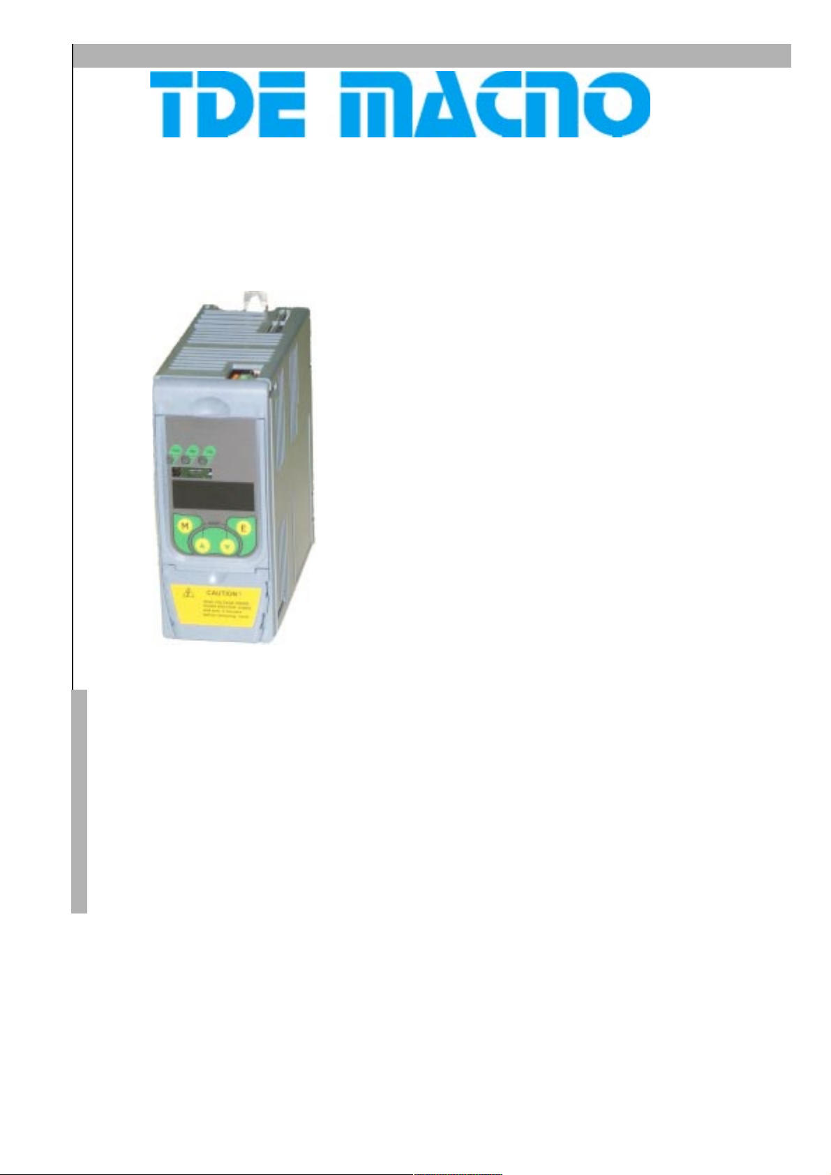
Torque control motor drives
DVS200
0,25 - 0,75 kW
User Manual: operation, specifications
and connections
Page 2

Information in this manual is subject to change without notice, and is not therefore binding
on TDE Macno S.p.A. in any way.
Read the safety precautions section before installing, connecting up, starting up or setting
up the drive.
Keep this manual in a safe place where it is readily available to all technical personnel
throughout the drives working life.
TDE Macno S.p.A.declines all responsibility for any errors that may occur in this manual
and for any damage that may be incurred as a result.
All rights reserved.
Revision: 01.00
Software version: 0B.00-00.00
Edition date: 10/06/04
Page 3

Key to Warning Symbols ............................................................................................................ 6
Chapter 1 - Safety Precautions ..................................................................................................7
1.1 Power and ground connections ....................................................................................................................................................... 9
Chapter 2 - General Description ............................................................................................... 11
Standard functions ............................................................................................................................................................................. 12
Advanced functions available from the complete version .................................................................................................................... 12
Options .............................................................................................................................................................................................. 12
Chapter 3 - Description, Components and Specifications ....................................................... 13
3.1. Storage and transport ................................................................................................................................................................... 13
3.1.1. General .................................................................................................................................................................................... 13
3.1.2. Drive identification ................................................................................................................................................................... 14
3.1.3. Data plate................................................................................................................................................................................. 14
3.2. Component identification ............................................................................................................................................................. 15
3.3. General specifications ................................................................................................................................................................. 16
3.3.1. Ambient conditions and standards............................................................................................................................................. 16
Disposing of the drive ................................................................................................................................................................ 17
3.3.2. Mains input and drive output connections ................................................................................................................................. 17
3.3.3. Mains input current .................................................................................................................................................................. 18
3.3.4. Output ...................................................................................................................................................................................... 18
3.3.5. DVS regulation and control section ........................................................................................................................................... 19
3.3.6. Precision.................................................................................................................................................................................. 19
Chapter 4 - Installation ............................................................................................................. 20
4.1. Mechanical specifications ........................................................................................................................................................... 20
4.2. Installation distances................................................................................................................................................................... 20
4.3. Motors......................................................................................................................................................................................... 21
4.3.1. Asynchronous AC motors .......................................................................................................................................................... 21
Chapter 5 - Electrical Connections ........................................................................................... 23
5.1. Accessing the electrical terminals ............................................................................................................................................... 23
5.2. The power section ....................................................................................................................................................................... 24
5.2.2 Power terminal wire cross sections ........................................................................................................................................... 24
5.2.3. The rectifier bridge and intermediate circuit ............................................................................................................................. 25
5.2.3. The inverter bridge ................................................................................................................................................................... 25
5.3. The control section ...................................................................................................................................................................... 27
5.3.1. The A313-XX control card ......................................................................................................................................................... 27
5.3.2. Control card terminal identification ........................................................................................................................................... 28
5.4. The RS 485 serial interface .......................................................................................................................................................... 29
5.4.1. General .................................................................................................................................................................................... 29
5.5. Typical Connection Schematics.................................................................................................................................................... 30
5.5.1. DVS drive connections ............................................................................................................................................................. 30
5.5.2. Design constraints .................................................................................................................................................................... 30
5.5.3 Parallel mains AC input connections to more than one drive....................................................................................................... 31
5.7. Chokes and filters ........................................................................................................................................................................ 32
5.7.1. Mains input chokes .................................................................................................................................................................. 32
5.7.2. Output chokes ........................................................................................................................................................................... 32
5.7.3. Noise filters .............................................................................................................................................................................. 33
5.7.3.1 External EMI filter connections ....................................................................................................................................... 33
5.8. Braking ........................................................................................................................................................................................ 34
5.9. Safety delay before work on the drive .......................................................................................................................................... 34
Chapter 6 - Using the Drives Control Keys ............................................................................. 35
6.1 Control keys and LEDs .................................................................................................................................................................. 35
6.2 Navigating the menus ................................................................................................................................................................... 36
6.5 Quick setup .................................................................................................................................................................................. 37
3
Page 4

Chapter 7 - Parameter Description .......................................................................................... 38
7.1 Parameters List ............................................................................................................................................................................ 38
7.2 Menu d - DISPLAY ....................................................................................................................................................................... 57
Basic ................................................................................................................................................................................................. 57
Overload............................................................................................................................................................................................ 57
Inputs/Outputs .................................................................................................................................................................................... 58
Pid .................................................................................................................................................................................................... 59
Alarm list ........................................................................................................................................................................................... 60
Drive Identification............................................................................................................................................................................. 60
Utility................................................................................................................................................................................................. 61
7.3 Menu S - START-UP ..................................................................................................................................................................... 62
Power Supply.................................................................................................................................................................................... 62
V/F Ratio .......................................................................................................................................................................................... 62
Motor Data ........................................................................................................................................................................................ 63
Commands & Referencies .................................................................................................................................................................. 64
Functions ........................................................................................................................................................................................... 65
Utility................................................................................................................................................................................................. 67
7.4 Menu I - INTERFACE.................................................................................................................................................................... 68
Digital Inputs Regulation Board .......................................................................................................................................................... 68
Digital Ouputs Regulation Board ......................................................................................................................................................... 69
Analog Inputs Regulation Board ......................................................................................................................................................... 70
Enabling Virtual I/O ............................................................................................................................................................................ 72
Serial Configuration ........................................................................................................................................................................... 75
7.5 Menu F - FREQ & RAMPS ............................................................................................................................................................ 78
Motorpotentiometer ........................................................................................................................................................................... 78
Reference Limits ................................................................................................................................................................................ 79
Reference Sources ............................................................................................................................................................................ 80
Multispeed Function .......................................................................................................................................................................... 81
Ramp Configuration ........................................................................................................................................................................... 82
Jump Frequencies ............................................................................................................................................................................. 84
7.6 Menu P - PARAMETERS............................................................................................................................................................... 86
Commands ........................................................................................................................................................................................ 86
Power Supply.................................................................................................................................................................................... 89
Motor Data ........................................................................................................................................................................................ 90
V/F Curve .......................................................................................................................................................................................... 91
Ouput Frequency Limit ....................................................................................................................................................................... 92
Slip Compensation ............................................................................................................................................................................. 93
Boost ................................................................................................................................................................................................. 94
Automatic Flux Regulation.................................................................................................................................................................. 95
Anti Oscillation Function .................................................................................................................................................................... 95
SW Current Clamp ............................................................................................................................................................................. 95
Current Limit ...................................................................................................................................................................................... 95
DC Link Limit ...................................................................................................................................................................................... 97
Over Torque Alarm Configuration........................................................................................................................................................ 98
Motor Overload Configuration ............................................................................................................................................................ 99
BU Configuration.............................................................................................................................................................................. 100
DC Brake Configuration .................................................................................................................................................................... 100
Autocapture function........................................................................................................................................................................ 101
Undervoltage Configuration.............................................................................................................................................................. 102
Overvoltage Configuration................................................................................................................................................................ 106
Autoreset Configuration.................................................................................................................................................................... 107
External Fault Configuration ............................................................................................................................................................. 107
Phase Loss Detection ....................................................................................................................................................................... 108
Voltage Reduction Configuration ...................................................................................................................................................... 108
Frequency Threshold ....................................................................................................................................................................... 109
Steady State Signalling .................................................................................................................................................................... 111
Heatsink Temperature Threshold ....................................................................................................................................................... 111
PWM Setting................................................................................................................................................................................... 112
Dead Time Compensation................................................................................................................................................................. 112
Display Setting ................................................................................................................................................................................ 113
Protection ........................................................................................................................................................................................ 113
7.7 Menu A - APPLICATION ............................................................................................................................................................. 114
PID Setting ...................................................................................................................................................................................... 114
4
Page 5

PID Gains......................................................................................................................................................................................... 118
PID Limits ........................................................................................................................................................................................ 118
7.8 Menu C - COMMANDS ............................................................................................................................................................... 120
Basic ............................................................................................................................................................................................... 120
Alarm Register Reset ....................................................................................................................................................................... 120
External Key .................................................................................................................................................................................... 120
Tuning ............................................................................................................................................................................................. 121
7.9 Menu H - HIDDEN ...................................................................................................................................................................... 122
Virtual I/O Commands ...................................................................................................................................................................... 122
Parameters Reading Extension ......................................................................................................................................................... 123
Serial Link Commands...................................................................................................................................................................... 124
Chapter 8 - Modbus RTU Protocol for DVS drives ................................................................ 125
8.1 Introduction ................................................................................................................................................................................. 125
8.2 The MODBUS Protocol ................................................................................................................................................................ 125
8.3 Message format .......................................................................................................................................................................... 125
8.3.1 The address ............................................................................................................................................................................ 125
8.3.2 The function code .................................................................................................................................................................... 125
8.3.3 CRC16..................................................................................................................................................................................... 126
8.3.4 Message synchronization ........................................................................................................................................................ 126
8.3.5 Serial line setting .................................................................................................................................................................... 126
8.4 Modbus functions for the drive .................................................................................................................................................... 127
8.4.1 Read Output Registers (03) ...................................................................................................................................................... 127
8.4.2 Read Input Registers (04) ........................................................................................................................................................ 128
8.4.3 Preset Single Register (06) ...................................................................................................................................................... 128
8.4.4 Read Status (07) ...................................................................................................................................................................... 128
8.4.5 Preset Multiple Registers (16) ................................................................................................................................................. 129
8.5 Error management ....................................................................................................................................................................... 129
8.5.1 Exception codes ...................................................................................................................................................................... 130
8.6 System configuration ...................................................................................................................................................................130
Chapter 9 - Troubleshooting ................................................................................................... 131
9.1 Drive Alarm Condition .................................................................................................................................................................. 131
9.2 Alarm Reset................................................................................................................................................................................. 131
9.3 List of Drive Alarm Events ........................................................................................................................................................... 131
Chapter 10 - EMC Directive, Declarations of EC-Conformity................................................ 133
5
Page 6
Key to Warning Symbols
This symbol identifies procedures or operating conditions that may lead to injury or even death if the specified
precautions are not followed.
This symbol identifies procedures or operating conditions that may lead to damage to or destruction of the
equipment if the specified precautions are not followed.
This symbol identifies procedures or operating conditions that are essential to the correct functioning of the
equipment.
NOTE !
This symbol identifies information, procedures or operating conditions of particular relevance.
6
Page 7
Chapter 1 - Safety Precautions
In compliance with EEC directives, make sure that all the safety devices required by EC standard 89/
392/CEE governing industrial automation have been incorporated in the drive before attempting to
operate it. These directives apply only in Europe and have no validity on the American continent.
This drive controls mechanical movements. It is the responsibility of the end user to ensure that
these movements do not themselves cause any danger. Do not bypass or tamper with the drive
manufacturers safety interlocks or operating limits.
Risk of fire and electric shock!
When using test apparatus like oscilloscopes to take measurements from electrically live equipment,
always connect the body of the oscilloscope to ground and always use a differential amplifier. To
ensure accurate readings, choose probes and terminals with care and make sure that the oscilloscope
is correctly set up. Refer to the manual provided by the oscilloscope manufacturer for details of how
to operate and adjust the oscilloscope correctly .
Risk of fire and explosion!
Installation of the drive in hazardous areas and in the presence of flammable substances or
combustible vapours or powders can lead to fire or explosion. Install the drive well away from
hazardous areas even if the controlled motor is suitable for use under such conditions.
Risk of crushing!
Incorrect lifting of the drive can cause serious or even fatal injury. Only suitably trained personnel
should lift the drive, and even then only with suitable lifting equipment.
Connect the drive and the motor to ground in compliance with applicable national electrical standards.
Replace any covers that may have been removed before powering up the drive. Failure to comply
with this precaution can lead to serious injury or even death.
This variable frequency drive is electrical equipment designed for use in industrial installations.
Parts of the drive are electrically live while it is functioning. The drive must therefore be installed
and opened only by a qualified electrician. Incorrect installation of the drive or the controlled motor
can damage the drive and lead to damage and injury.
The drive has no over-speed protection other than software based protection logic. Carefully follow
the instructions given in this manual and observe all local and national safety standards.
Always connect the drive to a protective earth (PE) through the ground terminals (PE2) and the
metallic casing (PE1). PIX drives and their AC power input filters have an earth leakage current
greater than 3.5 mA. EN 50178 standard specifies that in the presence of earth leakage currents
greater than 3.5 mA, the ground connection cable (PE1) must be fixed and must be doubled for
redundancy.
In the event of a fault, even if the drive has been disabled it may still cause sudden movements if it
has not been disconnected from the mains power.
Never open the drive or remove any covers while the drive is connected to the mains power supply.
See section 5.9 in this manual for the minimum delay that must be respected before any work on the
drives terminals or internal components can be performed.
Never connect the drive to mains supplies with voltage levels outside the specified range. Excess
voltage can damage the drives internal components.
It is forbidden to operate the drive without a correct ground connection. The casing of the motor
must also be grounded separately from the drive to avoid interference.
The ground connection must be comply with national electrical standards or the Canadian Electrical
Code. The drive must be grounded using a closed loop connector certified to UL and CSA standards
sized to match the gauge of the wire used. The connector must be fitted using the crimping tool
User Manual Chapter 1 - Safety Precautions 7
Page 8
specified by the connector manufacturer.
Never perform insulation testing between drive terminals or control circuit terminals.
Do not install the drive in environments where temperature exceeds the specified maximum. Ambient
temperature plays a major role in drive reliability.
If the drive displays any alarm condition, refer to the TROUBLESHOOTING section later in this manual
and recommence normal operation only once the problem has been solved. Do not use an external
routine or other such methods to reset alarms automatically.
The drive must be secured to a partition or panel constructed from heat resistant materials. The
temperature of the drives cooling fins can reach 90°C during normal functioning.
Do not touch or tamper with any drive component during normal functioning. In particular do not
alter gaps between insulation or remove insulation or covers from the drive.
Protect the drive against physical and environmental stress (high temperature, humidity, impact,
etc.).
Never apply voltage to the drives output terminals (U2, V2, W2). Likewise, never connect other
drives in parallel with the drives own outputs or bypass the drive by connecting its inputs directly to
its outputs.
Do not connect capacitive loads like power factor correction capacitors to the drives output terminals
(U2, V2, W2).
Only qualified electricians should install and start up the drive. The electrician so doing is directly
responsible for ensuring that there is an adequate ground connection and that power cables are
protected in accordance with local and national standards. The controlled motor must also be
protected against overload.
Do not perform dielectric rigidity testing on any parts of the drive. Only use appropriate test instruments
(with a minimum internal resistance of 10 k
ΩΩ
Ω/V) to measure signal voltage.
ΩΩ
NOTA!
NOTA!
8 Chapter 1 - Safety Precautions User Manual
Storage of the drive for periods longer than two years could lead to malfunctioning of the DC
link capacitors. These must be regenerated prior to use as follows.
Before starting up the drive, leave it connected to the mains power supply for at least two
hours with no load. The drive must be connected to the power supply but not enabled in
order to regenerate the capacitors.
The terms inverter, controller and drive are interchangeable in industrial automation
contexts. This manual uses the terms drive and inverter.
Page 9

1.1 Power and ground connections
1) TDE Macno S.P.A. drives are designed for use with standard three phase mains power supplies, symmetrical with
respect to ground (TN or TT mains supplies).
Single phase drives must be connected to one phase, neutral and ground. Three phase drives must be connected
to all three phases plus ground.
2) In the case of an IT mains supply, use a star/delta transformer with secondary wiring referenced to ground.
If IT mains power is used, loss of insulation in onen of the other devices connected to the same circuit
can cause the drive to malfunction if no star/delta transformer is provided.
User Manual Chapter 1 - Safety Precautions 9
Page 10

10 Chapter 1 - Safety Precautions User Manual
Page 11

Chapter 2 - General Description
DVS digital drives are designed to control the speed of three phase electric motors. They can control motors with a power
range from 0.25 kW to 0.75 kW (220 - 240 V) and from 0.35 HP up to 1 HP (220 V).
The drive rectifies the voltage of the mains power supply to obtain an intermediate circuit voltage, then uses an inverter bridge
applying sinusoidal PWM modulation to generate a three phase power supply with variable voltage and frequency permitting
regular, smooth motor control even at very low speeds.
Feed voltages to the various control cards are obtained from a switching power supply that also draws its power from the
intermediate circuit.
The inverter bridge is based on IGBT (Insulated Gate Bipolar Transistor) devices. Output is protected against short circuits
between the phases and to ground. If more than one motor is driven in parallel by a single drive (obviously of adequate power)
motors can be switched in and out independently even during normal drive functioning (see section 5.2.3).
If the motors used are not specifically designed for inverter control, a drop in output current of around 5 - 10% must be
allowed for. If nominal torque is demanded from such a motor at low speeds, an auxiliary motor cooling fan will be necessary
to dissipate the heat generated. If the necessary cooling assistance cannot be provided, then the motors will have to be oversized. In either case the user should contact the technical service of the motor manufacturer for further information.
If a motor has to function at a frequency greater than its nominal frequency, the user should again contact the manufacturers
technical service to ascertain what mechanical problems (bearing wear, balancing problems, etc.) could be incurred.
DVS drives can be controlled in a number of ways:
- via their control terminals
- using the control keys and display
- over an RS 485 serial line
- using a standard PC control program
Note!
The electronic control circuit terminals are electrically separate from the power circuit terminals, but the
control microprocessor is linked to the potential of the DC stage.
User Manual Chapter 2 - Introduction 11
Page 12

Standard functions
- Feed voltages generated from intermediate circuit voltage by switching technology.
- Reduced motor noise thanks to special PWM control technology.
- Output protected against short circuits between phases and to ground.
- Possibility of switching motors in and out of the drive output (see section 5.2.3).
- Protection against over-current, over-voltage and under-voltage.
- Ability to withstand mains power outages of up to 15 ms (see section 7.6 for automatic restart programming).
- Sinsoidal output current from sinusoidal PWM.
- Smooth, controlled motor rotation even at very low speeds.
- Programmable slip compensation to minimise load-related speed variation.
- Manual or automatic low speed voltage boost.
- Automatic voltage and frequency control in case of overload to avoid motor stalling.
- Keypad or RS 485 serial line parameter control.
- Linear or S acceleration/deceleration ramps.
- DC braking with the following control modes:
a - digital input control;
b - automatic braking below a set frequency;
c - pre-start braking for pumps and fans rotated by liquid or air movement prior to electrical start-up, to prevent switching
on a motor that is already rotating.
- Wide selection of V/f ratios.
- Overload level control.
- Non-volatile memory for the last 4 alarm event messages; messages not lost even if power is switched off.
- Set speed signalling via potential-free contacts or over a serial line for signalling e.g. zero speed.
- Digital parameter or serial line referencing.
Advanced functions available from the complete version
- Referencing with 0...10 V, -10...10 V, 0...20 mA, 4...20 mA analog signal.
- Choice of open loop or closed loop functioning.
Options
- RS 485 serial line control card (to be specified at time of order)
-E2PROM key for saving custom settings.
- Remote keyboard kit.
- Serial keyboard.
12 Chapter 2 - Introduction User Manual
Page 13

Chapter 3 - Description, Components and Specifications
3.1. Storage and transport
3.1.1. General
DVS drives are carefully packed for shipment. Transport must be undertaken using adequate means (see weights). Respect
all instructions and symbols printed on the packaging. The same applies to drives removed from their transport packaging for
installation in control cabinets.
Perform the following checks as soon as you receive your drive.
- Check that the packaging has not been visibly damaged.
- Check that the details on the delivery bill correspond to those of the original order.
Unpack the drive carefully and perform the following checks.
- Check that no part of the drive has been damaged during transport.
- Check that the drive delivered corrsponds to that ordered.
If any damage is found, or if the drive is either incomplete or incorrect, notify the suppliers sales department immediately.
The drive must only be stored in dry places and within the specified storage temperature range.
NOTA!
Excessive temperature variations can cause condensation to form inside the drive. While this may be
acceptable under certain storage conditions (see section 3.3.1 Ambient conditions and standards),
the presence of condensation is absolutely unacceptable under normal drive operating conditions. Before
powering your drive on for the first time, always make sure that there is no condensation inside it!
User Manual Chapter 3 - Description, Components and Specifications 13
Page 14
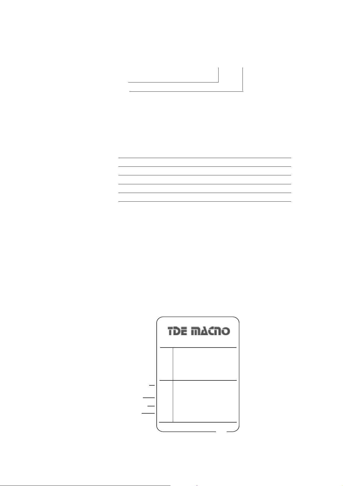
3.1.2. Drive identification
The drives basic technical details are shown in its identification and on its data plate. Example:
DVS - 025
Drive series
Motor power
Drive series
Input power
Output power
Software
Serial interface
EMC filter
Choose a drive to suit the nominal current of the controlled motor. The drives nominal output current must be equal to or
greater than that required by the controlled motor.
The speed of an asynchronous motor depends on the number or terminal pairs it has and on its operating frequency (as
specified on the data plate and in the catalogue). If a motor has to be run above its nominal speed, consult the manufacturers
technical service to ascertain what mechanical problems may be incurred (bearing wear, balancing problems, etc.). Also
contact the manufacturers technical service to ascertain what thermal problems may be incurred if the motor has to be run
at a frequency below approximately 20 Hz (e.g. insufficient cooling if no auxiliary ventilation is provided).
DVS
220Vac- 1 phase
025=250W - 037=370W - 055=550W - 075=750W
Standard
Rs485
On board
3.1.3. Data plate
Check that the specifications on the drives data plate correspond to the original order.
Drive series
Input specifications
Load specifications
Pollution degree
MODEL
OPTION
S/N
INPUT
OUTPUT
LOAD
IP
DVS - 075
_
_
AC 220V-15% / 240V +10%
8A 50/60Hz 1PHASE
AC 0 / 230V 3,9A 0,1 / 500 Hz
0,75 kW AC 3Ph MOTOR
20
CE
made in Italy
14 Chapter 3 - Description, Components and Specifications User Manual
Page 15
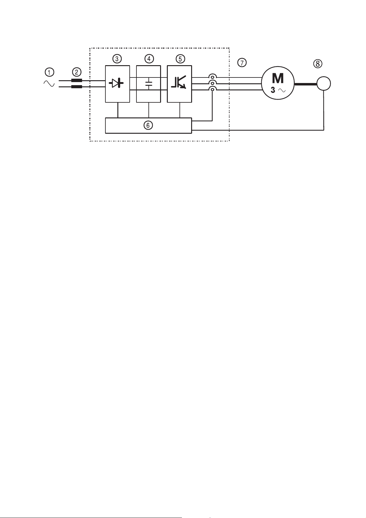
3.2. Component identification
T
Figure 3.2.1: Basic schematic of a frequency inverter
Inverters convert a constant frequency, constant voltage mains supply into DC voltage. From this DC voltage, they then
generate a three phase AC supply with variable voltage and frequency. This variabile three phase power enables smooth
speed control of three phase asynchronous motors.
1 Mains supply: 220 V - 240 V single phase.
2 Mains choke (see section 5.7.1).
3 Rectifier bridge.
Uses full wave technology to convert AC into DC voltage.
4 Intermediate circuit.
Comprises precharge resistors and smoothing capacitors. DC voltage (UDC) = 1.41 x mains line voltage (ULN)
5 IGBT inverter bridge.
Converts DC voltage into three phase AC voltage with variable amplitude and frequency.
6 Configurable control section.
Comprises all the necessary cards for the control and regulation of the closed or open loop power section. Commands,
references and feedbacks are all connected to these cards.
7Output.
AC power variable between 0 and 94% of mains power (ULN).
8 Speed feedback (e.g. tachometer)
User Manual Chapter 3 - Description, Components and Specifications 15
Page 16
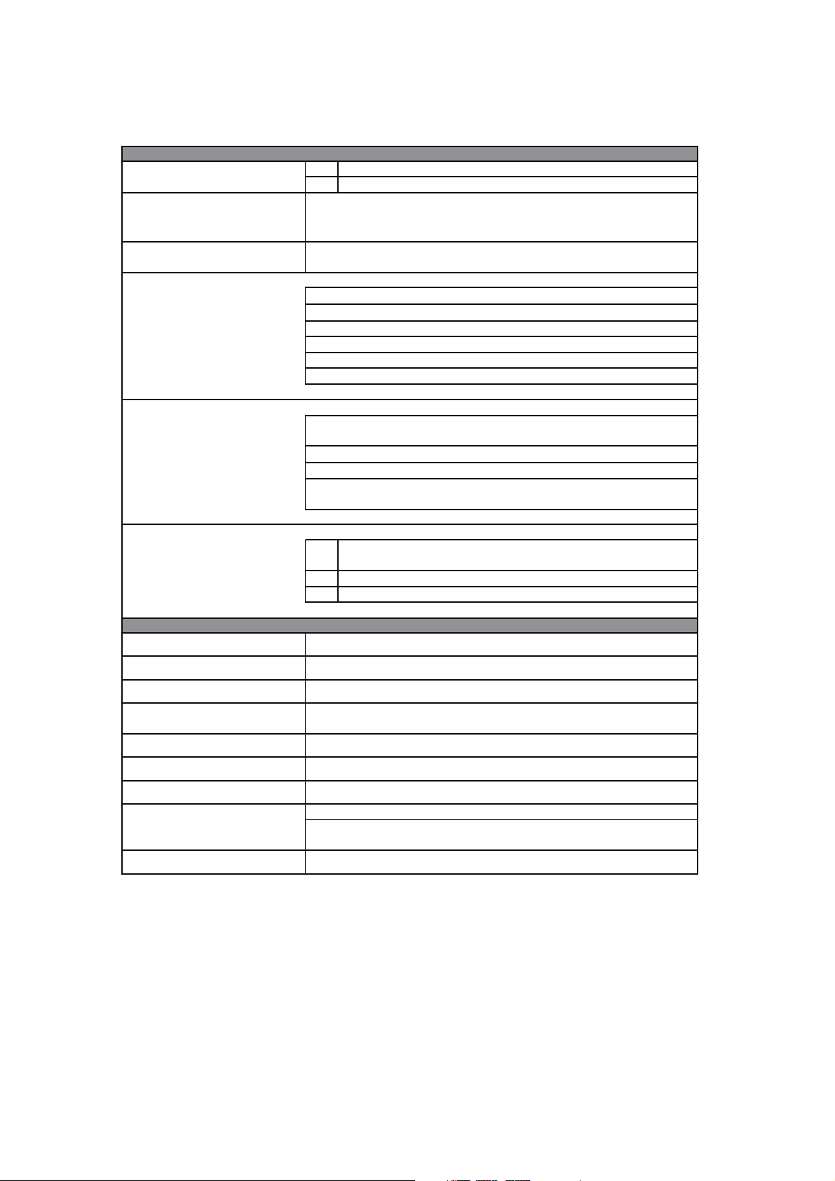
3.3. General specifications
3.3.1. Ambient conditions and standards
Table 3.3.1.1: Ambient conditions and standards
ENVIRONMENT
T
Ambient temperature
A
Installation location
Installation altitude
Temperature:
operation
operation
storage
transport
[°C]
[°F]
Pollution degree 2 or better (free from direct sunligth, vibration, dust,
corrosive or inflammable gases, fog, vapour oil and dripped water, avoid
Up to 1000 m (3281 feet) above sea level; for higher altitudes a current
reduction of 1.2% for every 100 m (328 feet) of additional height applies .
1)
2)
0 … +40; +40…+50 with derating
32 … +104; +104…+122 with derating
saline environment)
0…40°C (32°…104°F)
0…50°C (32°…122°F)
-25…+55°C (-13…+131°F), class 1K4 per EN50178
-20…+55°C (-4…+131°F), for devices with keypad
-25…+70°C (-13…+158°F), class 2K3 per EN50178
-20…+60°C (-4…+140°F), for devices with keypad
Air humidity:
operation
storage
transport
Air pressure:
operation [kPa]
storage [kPa]
transport [kPa]
General standards
Safety
Climatic conditions
Clearance and creepage
Vibration
EMC compatibility
Rated input voltages
Protection degree
Approvals
1)
Ambient temp parameter = 40°C (104°F).
Ambient temperature = 0 ... 40°C (32°...104°F)
Over 40°C (104°F):
- 2% reduction in output current.
5%to85%,1g/m
5% to 95 %, 1 g/m
A light condensation of moisture may occur for a short time occasionally if the device
STANDARD
EN 60721-3-3, class 3K3. EN 60068-2-2, test Bd.
EN 50178, UL508C, UL840. Overvoltage category for mains connected
EN61800-3 (see “EMC Guidelines” instruction book)
IP54 for the cabinet with externally mounted heatsink; only for
sizes 1007… 3150 (230V…480V) and 2002 … 3020 (575V)
3
to 25 g/m3without moisture condensation or icing
(Class 3K3 as per EN50178)
3
to 29 g/m3(Class 1K3 as per EN50178)
3)
95 %
is not in operation (class 2K3 as per EN50178)
86 to 106 (class 3K3 as per EN50178)
86 to 106 (class 1K4 as per EN50178)
70 to 106 (class 2K3 as per EN50178)
EN 61800-1, IEC 143-1-1.
EN 50178, UL 508C
circuits: III; degree of pollution 2
EN 60068-2-6, test Fc.
IEC 60038
IP20 according to EN 60529
CE, UL, cUL
60 g/m
4)
TGy0020
3) Higher airborne humidity values with temperature at
40°C (104°F) or if drive temperature suddenly rises
between -25 ...+30°C (-13°...+86°F).
4) Higher airborne humidity values if drive temperature
2)
Ambient temp parameter = 50°C (122°F).
suddenly drops between 70...15°C (158°...59°F).
Ambient temperature = 0 ... 50°C (32°...122°F):
Over 40°C (104°F):
20% reduction in output current.
16 Chapter 3 - Description, Components and Specifications User Manual
Page 17

Disposing of the drive
DVS drives must be disposed of as electronic waste in compliance with national legislation.
The front covers are made from recyclable ABS.
3.3.2. Mains input and drive output connections
DVS drives must be connected to a mains supply capable of providing symmetrical short circuit power better than or equal
to the values given in table 3.3.2.1. See section 5.7.1 for information on the addition of mains chokes.
See table 3.3.2.1 for the permitted mains voltages. Cyclical phase direction is irrelevant. Voltages below the minimum
tolerance threshold cause the drive to lock.
The drive can be restarted automatically after an alarm condition occurs (see section 6.15 for further details on this function).
NOTA!
DVS drives and mains input filters have earth leakage currents greater than 3.5 mA. EN 50178 standard requires that in the
presence of earth leakage currents greater than 3.5 mA, the ground connection (to the PE terminal) must be fixed.
Under certain circumstances it may be essential to add mains chokes and EMI filters to the drive input.
Refer to the Chokes and filters section.
User Manual Chapter 3 - Description, Components and Specifications 17
Page 18
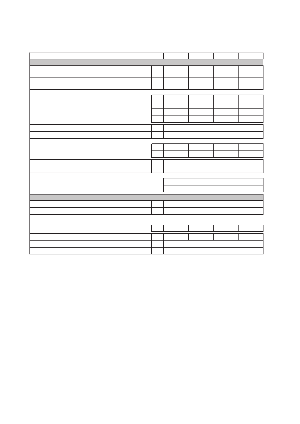
Table 3.3.2.1-A: I/O specifications for drive models in Kw/Hp at 230 V
DVS Drive Type - Hp rating 025 037 055 075
OUTPUT
Inverter Output (IEC 146 class1), Continuous service
(@230V)
Inverter Output (IEC 146 class2), 150% overload for 60s
(@230V)
PNmot (recommended motor output):
=230Vac; fSW=default; IEC 146 class 1
@U
LN
@ULN=230Vac; fSW=default; IEC 146 class 2
@ULN=230Vac; fSW=default; IEC 146 class 1
@ULN=230Vac; fSW=default; IEC 146 class 2
U2Max output voltage
f2Max output frequency (*)
I2NRated output current :
=230Vac; fSW= default; IEC 146 class 1
@U
LN
@ULN=230Vac; fSW=default; IEC 146 class 2
fSWswitching frequency (Default)
fSWswitching frequency (Higher)
Derating factor:
K
for ambient temperature
T
K
for switching frequency
F
INPUT
ULNAC Input voltage
AC Input frequency
INAC Input current for continuous service :
- Connection without 3-phase reactor
@ 230Vac; IEC 146 class 1
Max short circuit power without line reactor (Zmin=1%)
Overvoltage threshold
Undervoltage threshold
[kVA]
[kVA]
[kW]
[kW]
[Hp]
[Hp]
[V]
[Hz]
[A]
[A]
[kHz]
[kHz]
[V]
[Hz]
[A]
[kVA]
[V]
[V]
0,77 1,10 1,43 1,87
0,70 1,00 1,30 1,70
0,25 0,35 0,55 0,75
0,25 0,35 0,55 0,75
0,35 0,50 0,75 1,00
0,35 0,50 0,75 1,00
0.94 x ULN (AC Input voltage)
500
1,5 2,4 3,3 4,3
1,4 2,2 3,0 3,9
12
18
0.8 @ 50°C (122°F)
0.7 for higher f
sw
220 V -15% … 240 V +10%, 1-PHASE
50/60 Hz ±5%
3,0 4,5 6,0 8,0
410VDC (@ 230VAC)
230VDC (@ 230VAC)
3.3.3. Mains input current
The mains input current to the drive depends on the duty status of the controlled motor. Table 3.3.2.1
shows nominal continuous duty values (IEC 146 class 1) with typical output power factors for each
model of drive.
3.3.4. Output
The output from DVS drives is protected against short circuits between phases and to ground.
NOTA!
The nominal continuous output current value (I
frequency (KF) if higher than the default frequency:
I
= I2N x KV x KT x Ksw (see table 3.3.2.1 for reduction factors), with a maximum overload capacity of I
CONT
for 60 seconds.
18 Chapter 3 - Description, Components and Specifications User Manual
It is forbidden to connect any external voltage to the drives output terminals! Nevertheless, once a motor
has been disabled, it can be disconnected from the drive output while the drive is still functioning.
) depends on mains voltage (Kv), ambient temperature (KT) and switching
CONT
= 1.5 x I
MAX
CONT
Page 19

Recommended motor power
The combinations of nominal motor power and inverter model specified in table 3.3.2.1 is based on the use of motors whose
nominal voltages correspond to that of the mains power supply.
If the motors involved have other voltages, select the drive model on the basis of nominal motor current.
NOTA!
Maximum permitted overload: 136% . I2N cl.1 º 150% . I2N cl.2.
Table 3.3.3.1 shows nominal current values for the most typical duty profiles (ambient temperature =
40°C, standard switching frequency).
A similar criterion should be applied to drive operation with additional declassing factors.
3.3.5. DVS regulation and control section
1 analog input 1 analog input, programmable as:
. Analog voltage input 0-10 V 0.5 mA max, 10 bit + sign (default)
. Analog current input 0...20 mA, 10 V max, 10 bit
. Analog current input 4...20 mA, 10 V max, 10 bit
4 digital inputs 4 programmable digital inputs: 0 - 15V / 7 mA
. Digital input 1 = Run (default)
. Digital input 2 = NO external fault (default)
. Digital input 3 = Reverse (default)
. Digital input 4 = Freq Sel 1 (default)
1 digital output 1 programmable digital output:
. Digital output 1 = Drive alarm state (default)
Relay type output: 230Vac-0.2A / 30Vdc-1A
Auxiliary voltages from drive terminals
Capacity: + 15Vdc, 300mA (terminal 4)
+ 10Vdc, 50mA (terminal 11)
Tolerance: + 10Vdc ±3 %
+ 15Vdc ±5 %
3.3.6. Precision
Reference: Resolution of reference from analog inputs to terminals 0.1 Hz
[full scale function and 1 bit for sign]
Resolution of reference from serial line 0.01 Hz
Open loop speed: Load related speed loss can be partly compensated for using slip compensation.
Precision nevertheless also depends on the characteristics of the controlled motor.
User Manual Chapter 3 - Description, Components and Specifications 19
Page 20
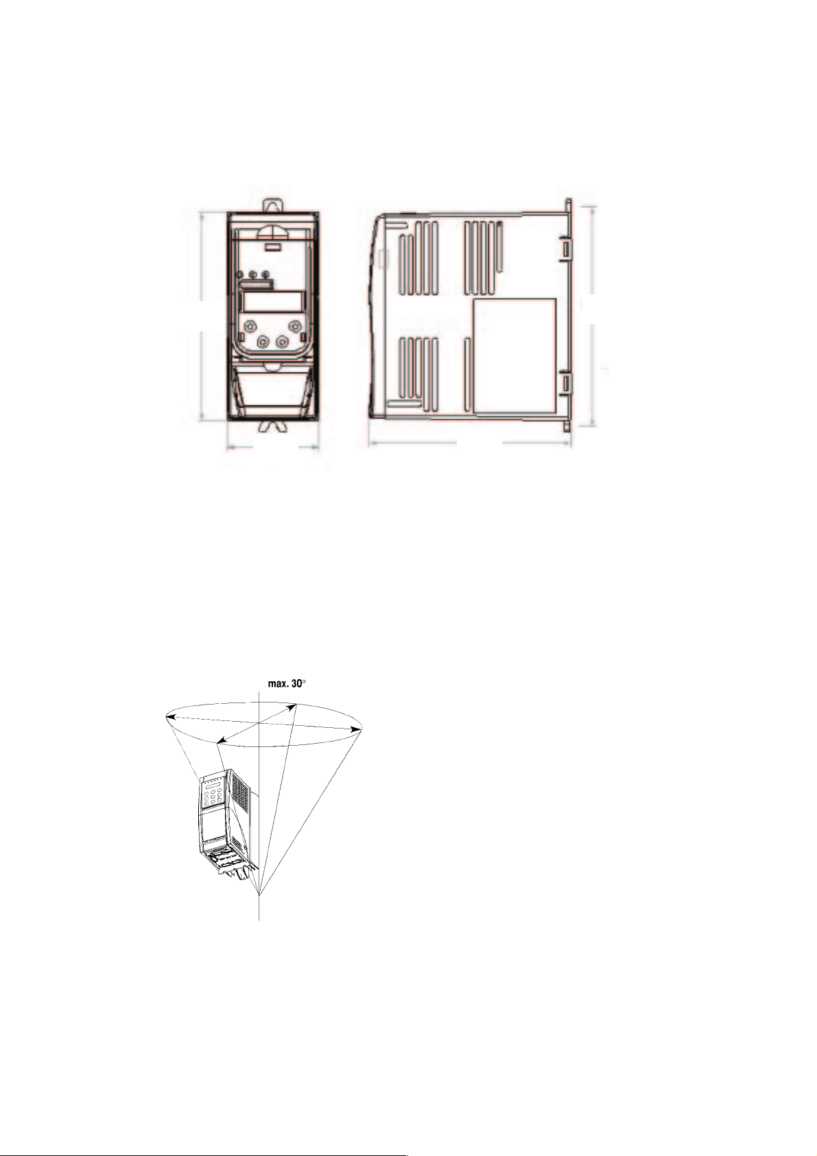
Chapter 4 - Installation
4.1. Mechanical specifications
129
57
4.2. Installation distances
NOTA!
Respect the distances given in this manual when installing the drive. Use only appropriate tools and
equipment. Incorrect handling and the use of improper tools can damage the drive.
186
127
Figure 4.1.1: DVS drive dimensions
Figure 4.2.1: Maximum angle
Maximum permitted angle to the vertical: 30°.
NOTA!
20 Chapter 4 - Installation User Manual
Install the drive in such a way as to ensure free circulation of air all around it. Leave a gap of at least 150
mm above and below the drive. Leave at least 50 mm of free space in front of the drive .
Do not install other items of equipment that generate heat near the drive.
Check the terminal connections for tightness after a few days of operation.
Page 21
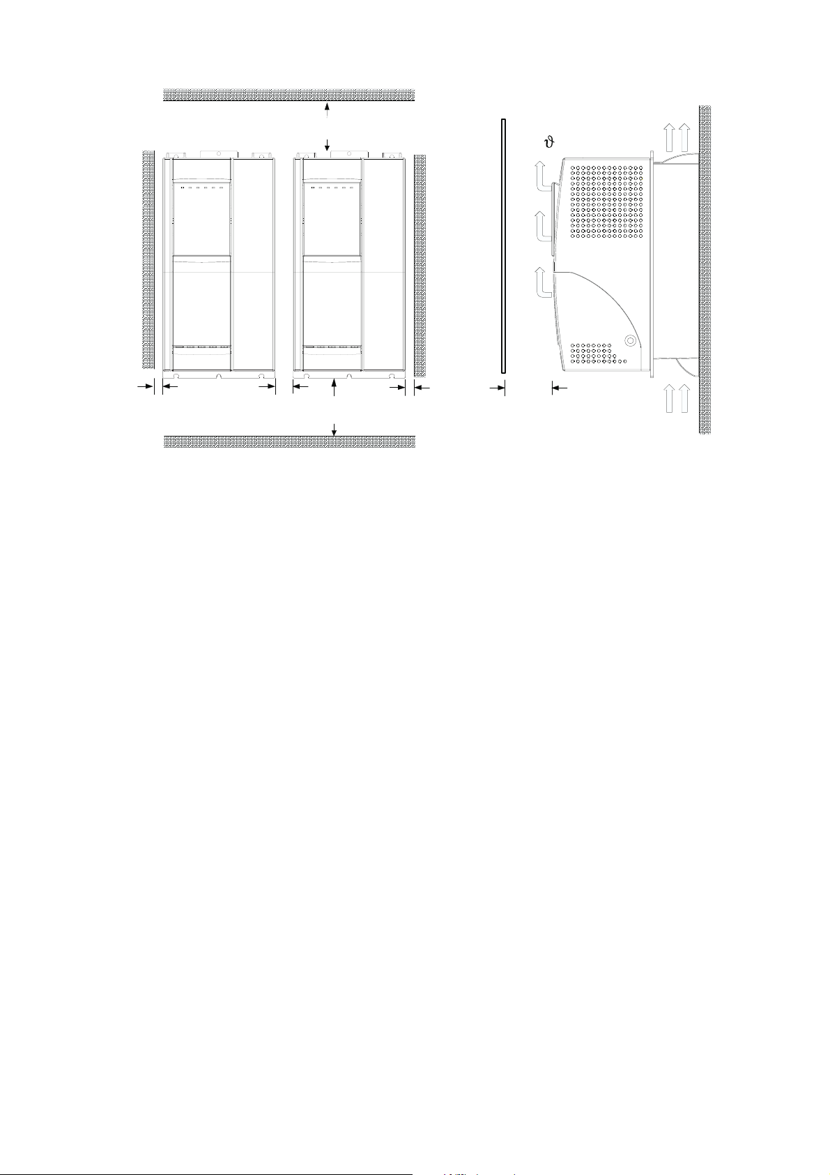
Figure 4.2.2: Installation distances
10 mm ( 0.4" )
20 mm ( 0.8" )
6"150 mm ( )
6"150 mm ( )10 mm ( 0.4" )
2" )50 mm (
4.3. Motors
DVS drives are designed for open or closed loop control of standard asynchronous motors.
4.3.1. Asynchronous AC motors
FOR BEST RESULTS:
Choose an asynchronous motor with a minimum slip of 3-5 %, with a single cage rotor, designed for use with an
inverter.
a) Minimum motor size. Nominal motor current must not be less than 30% of nominal drive current @ 230V.
b) General purpose motors (i.e. motors not specifically designed for inverter control) must only be used if an additional
output choke is fitted.
c) We recommend that you use special motors with reinforced insulation designed for inverter control. Motors of this
type do not require the drive to be fitted with an output choke.
The electrical and mechanical specifications of standard asynchronous motors refer to a specific functioning range. When
controlling motors of this type with an inverter, always bear the following points in mind.
Can standard asynchronous motors be used?
DVS series drives can be used with standard asynchronous motors. Certain characteristics of these motors, however, have
a major influence on performance. Pay special attention to the following considerations. Also bear in mind what section
3.3.4 Output has to say about motor power ratings and voltages.
Star or delta connection?
Motors can be wired up either in a star or a delta configuration. Star wired motors are generally easier to control and star wiring
is therefore to be preferred under most circumstances.
User Manual Chapter 4 - Installation 21
Page 22

Cooling
Asynchronous motors are normally cooled by a fan keyed directly on to the motor shaft. Care must be taken, however,
because fan efficiency drops at low motor speeds and the motor may receive insufficient cooling. Discuss motor operating
conditions with the motor manufacturers technical service to ascertain whether it is necessary to provide additional ventilation
(forced cooling).
Functioning at speeds above nominal speed
If a motor has to operate above its nominal speed, contact the manufacturers technical service to ascertain what mechanical
problems (bearing wear, balancing problems etc.) and what electrical losses may occur as a result.
Motor specifications you must know for inverter control
Motor data plate specifications:
- Nominal motor voltage
- Nominal motor current
- Nominal motor frequency
- Nominal motor speed
- Power factor (Cos ϕ)
- Number of terminal pairs
- Connection type (star/delta)
Motor protection
Use of Klixon protectors in motor windings
The contacts of the Klixon overheating protectors can be used to disable the motor either via auxiliary control circuits or
using the input to signal an alarm condition.
NOTA!
Drive current limitation
Current limitation can be used to protect the motor against damaging overloads. To do so, the current limit and overload
control parameters must be set so that current to the motor always remains within the motors acceptable limits.
NOTA!
Output chokes
In certain cases output chokes may be needed to protect the winding insulation of standard motors. See section 5.7.2.
Output chokes.
The motors Klixon interface circuit can be considered and managed to all intents and purposes like a
signaling circuit. Connections to the motors Klixon protectors must therefore use a shielded twisted
pair cable laid if possible not parallel with other motor cables or at a distance of at least 20 cm (8 inches)
from them.
Bear in mind that current limitation can only protect the motor against overheating caused by overload,
and not against overheating caused by inadequate cooling.
Always fit the windings of motors destined for use at low speeds with the necessary temperature control
plates!
22 Chapter 4 - Installation User Manual
Page 23
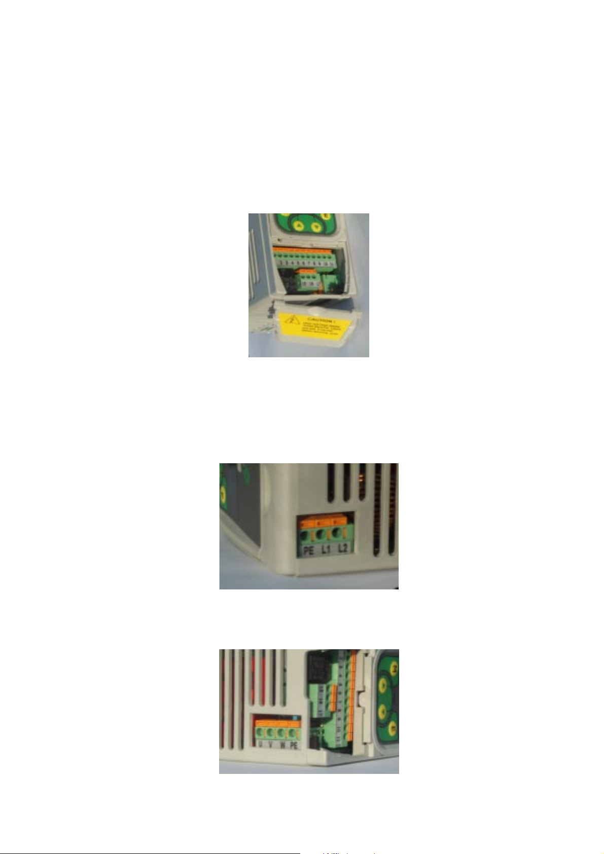
Chapter 5 - Electrical Connections
5.1. Accessing the electrical terminals
NOTA!
Remove the terminal cover to access the control card terminals. If all the terminals are going to be used, it may prove useful
to cut a corner off the cover to facilitate cable access.
Observe the safety precautions given elsewhere in this manual. The terminal covers can be removed
without the use of force. Use only appropriate tools.
Figure 5.1.1: Accessing the control terminals
Figure 5.1.2: Accessing the power terminals
Figure 5.1.3: Accessing the motor terminals
User Manual Chapter 5 - Electrical Connections 23
Page 24
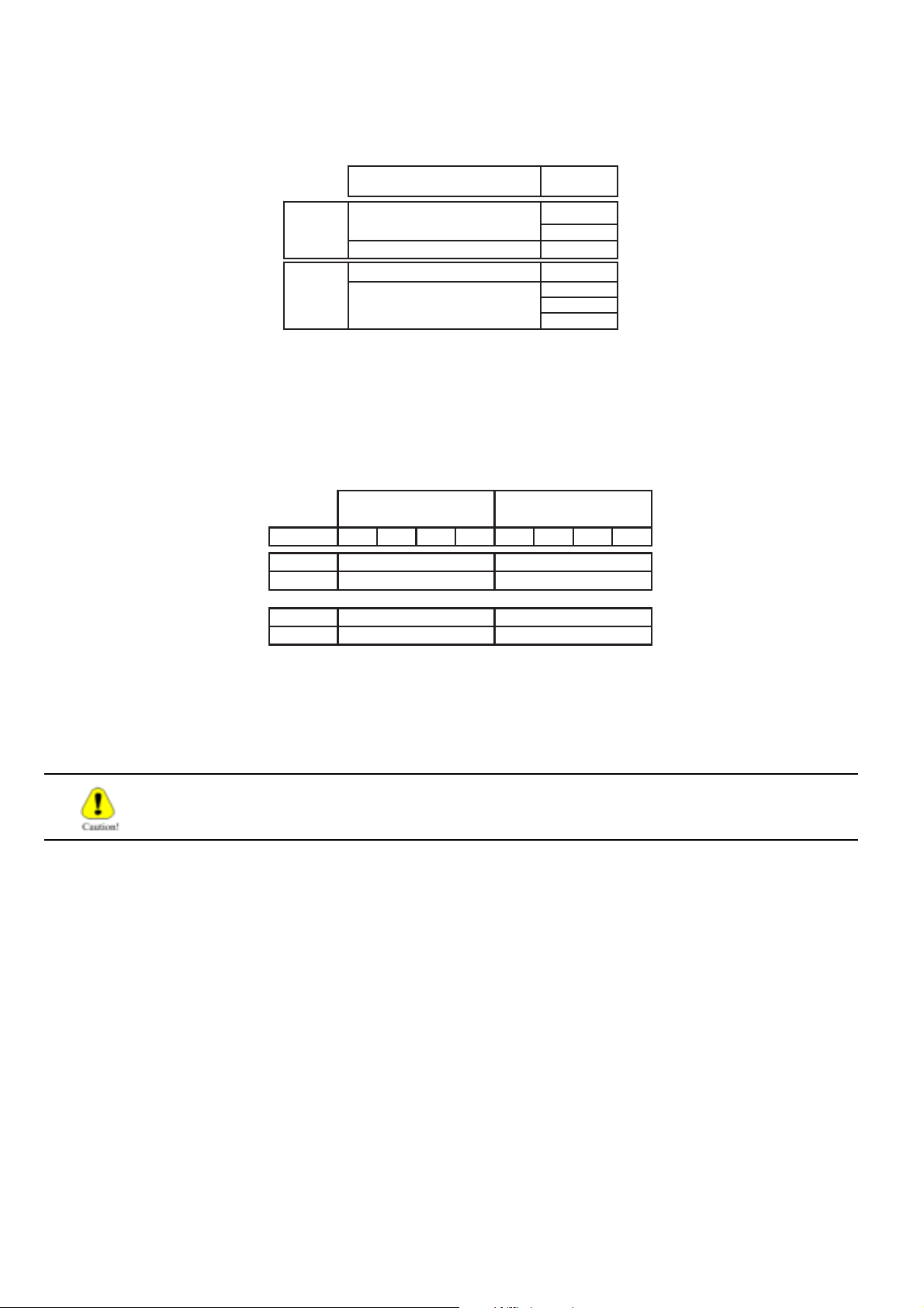
5.2. The power section
Table 5.2.1.1: Power terminal identification and functions
230 V SINGLE PHASE MAINS
TOP
GROUND CONNECTION
GROUND CONNECTION
BOTTOM
THREE PHASE POWER TO
5.2.2 Power terminal wire cross sections
Minimum section
size 025 037 055 075 025 037 055 075
L1, L2
PE
PE
U, V, W 1,5 2,5
FUNCTION
POWER
MOTOR
2
]
[mm
TERMINAL
Maximum section
1,5 2,5
1,5 2,5
1,5 2,5
L2
L1
PE
PE
W
V
U
[mm2]
NOTA!
Use only copper wire rated for 75°C.
If the output of a DVS drive short circuits to ground, current in the motors ground wire may reach
up to twice nominal current I2N.
24 Chapter 5 - Electrical Connections User Manual
Page 25
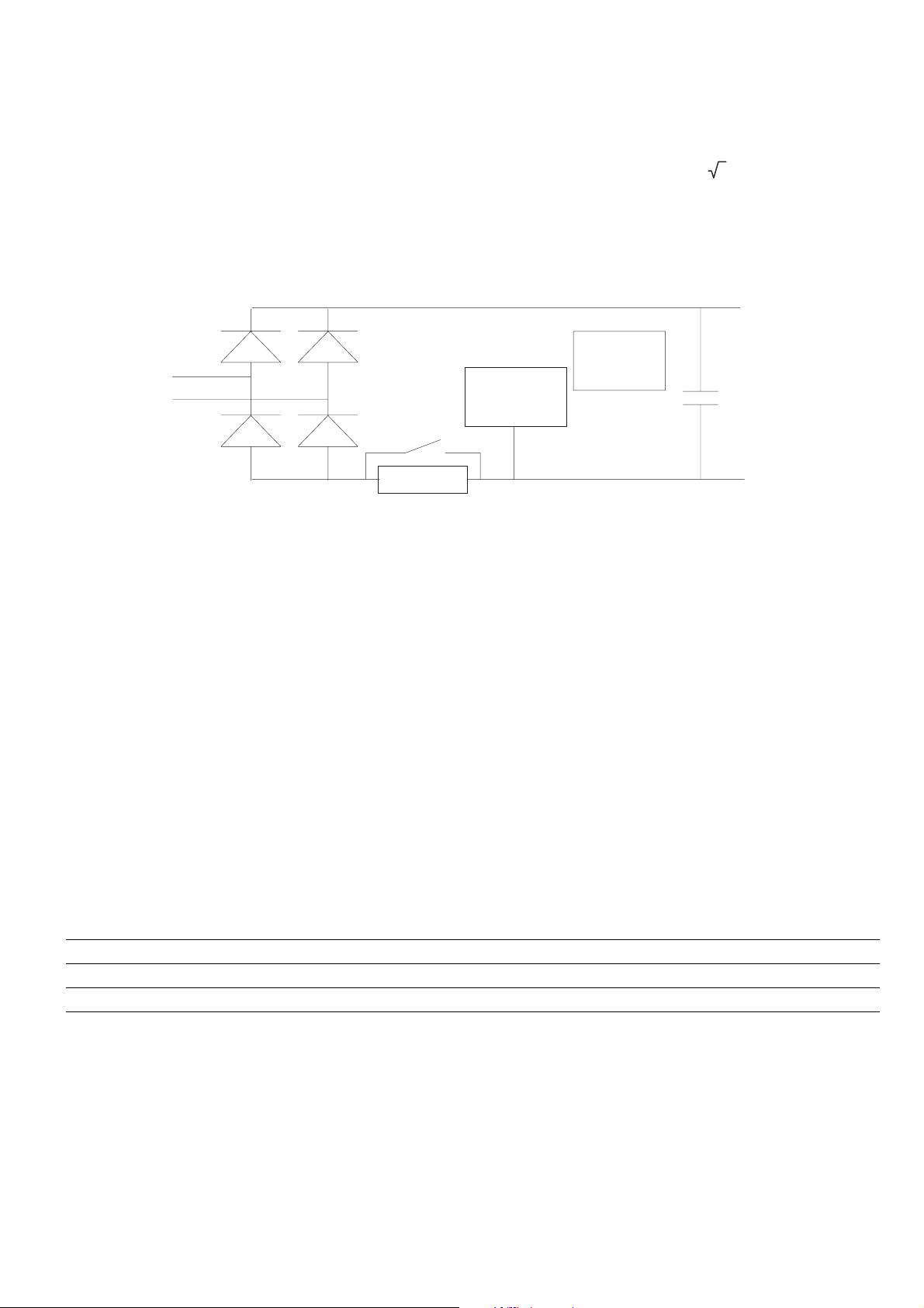
5.2.3. The rectifier bridge and intermediate circuit
Mains power is rectified and filtered by capacitors. All models of PIX drives incorporate a precharge resistance diode bridge.
If over-voltage (OV signal) or under-voltage (UV signal) occurs in the intermediate circuit, no power can be drawn from it
because the inverter bridge locks.
During normal functioning, the DC voltage of the intermediate circuit UDC has a value equal to ULN * 2. If the motor is turned
by its load (as occurs during deceleration or braking), power flows into the intermediate circuit through the inverter bridge.
Voltage in the intermediate circuit therefore increases. The inverter bridge locks at a predetermined voltage, and the contacts
between terminals 1 and 3 open (provided the relay has been programmed as an alarm state signal). See section 6.15 for
details on resetting.
I/O regolazione
U
LN
U
LN
Res. Precarica
Figura 5.2.3.1 The rectifier bridge and intermediate circuit
The drive can be restarted automatically after an alarm condition. (See section 6.15 for further information on automatic
restarting.)
Locking can also be prevented by extending the deceleration ramp.
Microcontrollore
della regolazione
Optoisolamento
U
DC
5.2.3. The inverter bridge
The inverter bridge features IGBT (Insulated Gate Bipolar Transistor) technology in all models of DVS drive. The inverter
bridge is protected by internal circuitry against over-voltage, over-current, short circuit between phases and short circuit to
ground. In the event a fault, the inverter bridge locks and the contacts between terminals 1 and 3 open (provided the relay has
been programmed as an alarm state signal). See section 6.15 for information on resetting.
The drive can be restarted automatically after an alarm condition. (See section 6.15 for further information on automatic
restarting.)
Table 5.2.4.1: Inverter bridge protection alarm signalling
Signal Lock caused by
OV Over-voltage
OC Over-current, short circuit between phases
OC Short circuit to ground
User Manual Chapter 5 - Electrical Connections 25
Page 26
Variable voltage output is derived from the intermediate circuit voltage using PWM technology. Special sinusoidal modulation
in conjunction with the motors own inductance produces an extremely good sinusoidal curve for the output current I2. The
voltage/frequency ratio is programmable and can be adapted to suit the motor being controlled.
More than one motor can be connected in parallel to the drive output. Motors may run at different speeds even though they
have the same number of terminal pairs, because motor slip can vary with the load applied and motor characteristics may
vary too. Motors can also be switched in and out individually, though great care must be taken when doing so.
Switching a motor in or out causes voltage peaks by interrupting an inductive current flow. These voltage peaks do not
normally disturb the drive output provided the motor is a low power model and other motors remain connected to the inverter
after it is switched out.
If the motor being switched out is the last motor connected to the drive, make sure that the motors
magnetising current has dropped to zero before switching it out. the best way of doing this is to lock the
inverter bridge and disconnect the motor only after a fixed delay calculated to suit the characteristics of
the motor, in practice from about 0.5 seconds up to a number of seconds.
Motors can likewise be switched in to an already functioning inverter one at a time. If you wish to do so, bear in mind that the
instant the motor is connected its inrush current far higher than its nominal current. The drive must therefore be carefully
selected so that inrush currents do not exceed the drives nominal current. You must also consider the overload that the drive
is able to cope with if the duty cycle during which the new motor is connected coincides with the limited period for which
overload is permitted.
More than one inverter cannot work directly in parallel.
26 Chapter 5 - Electrical Connections User Manual
Page 27
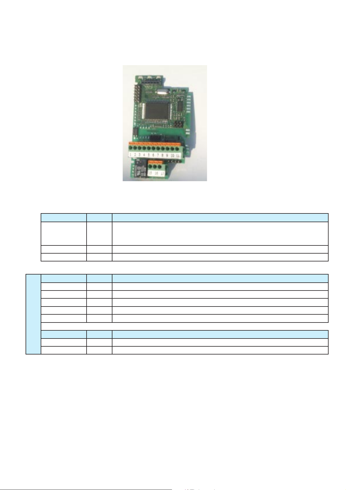
5.3. The control section
5.3.1. The A313-XX control card
Figure 5.3.1.1: The A313-XX control card
D1 D2 D3
C1
HIGH VOLTAGE (DC-link)
C2
OPTO-INSULATION BARRIER- - - - - - - - - - - - - - - - - - - - - - - - - - - - - - - - - -
C3
LOW VOLTAGE (motor side)
J5 - J7
S1 C4
A313XX
LED Colour
D1 yellow Lit = drive power
D2 green Lit = Run command enabled and active
D3 red Lit = drive in alarm state
Connector PIN N°
C1 6 Programming key connector
C2 6 Keypad connector
C3 7 Control terminals
C4 3 Serial line terminals
DVS
S1 4 Slot for optional serial line
Jumper Default
J5 0 Transforms analog voltage input into current input
J7 0 Links control card 0V to ground
Table 5.3.1.1: LEDs, jumpers and connectors on the A313-XX
Function
Flashing = parameters changed but not saved
Off = attempting to change unmodifiable parameter in Run
Function
Function
User Manual Chapter 5 - Electrical Connections 27
Page 28
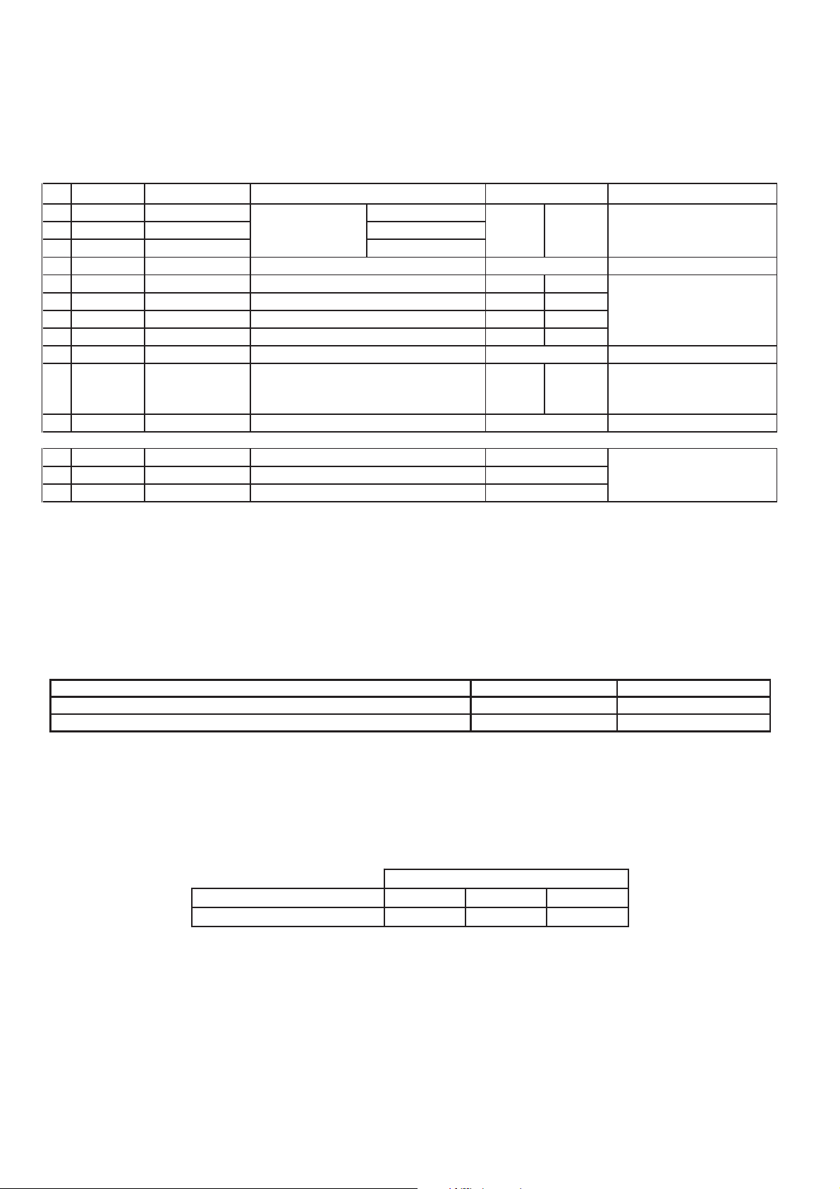
5.3.2. Control card terminal identification
Figure 5.3.2.1: Control card terminal identification
No. Terminal Description FUNCTION Signal type
1 REL-CM Digital output 1 Common
2 REL-NO Digital output 1 Norm.Open
3 REL-NC Digital output 1 Norm.Closed
Programmable
relay output
Default
I-100=1 ALARM
Switching capacity: 230
Vac,0.2A;30Vdc,1A
4 +15V +15 V OUT Auxiliary power for digital inputs 15V +/-5% 300mA
5 IN 1 Digital input 1 Programmable digital input 1 I-100=1 RUN
6 IN 2 Digital input 2 Programmable digital input 2 I-100=3 EF
7 IN 3 Digital input 3 Programmable digital input 3 I-100=2 REV
8 IN 4 Digital input 4 Programmable digital input 4 I-100=7 Freq.Sel.
7mA at 15V opto-
couplers for PNP logic,
active connected to
+15V
9 GND 0 V Reference ground for analog input
IN AN 1
Analog input 1
Programmable analog input
I-200=1 0-10V10
0-10V, 0-20mA, 4-20
mA
11 +10V + 10 V OUT Auxiliary power for potentiometer 10 V +/-3% 50mA
15 GND 0V Reference ground
16 FB + Link + Serial line +
RS 485
17 FB - Link - Serial line -
Maximum wire sections for control card terminals
Table 5.3.2.1: Maximum wire sections for control card terminals
Control connection data
Rigid / Flexible / wire size
Flexible with spade end with/without insulating collar
Stripping length
Maximum wire length
Table 5.3.2.2: Maximum wire length
Wire section [mm2]
Maximum length [m]
2
]/[mm2]/AWG
[mm
[mm
[mm]
2
]
Maximum wire length
0,5 0,75 1
30 60 90
0,22-1 / 0,22-1 / 26-18
0,25 - 0,34 / 0,25 - 0,34
10
28 Chapter 5 - Electrical Connections User Manual
Page 29
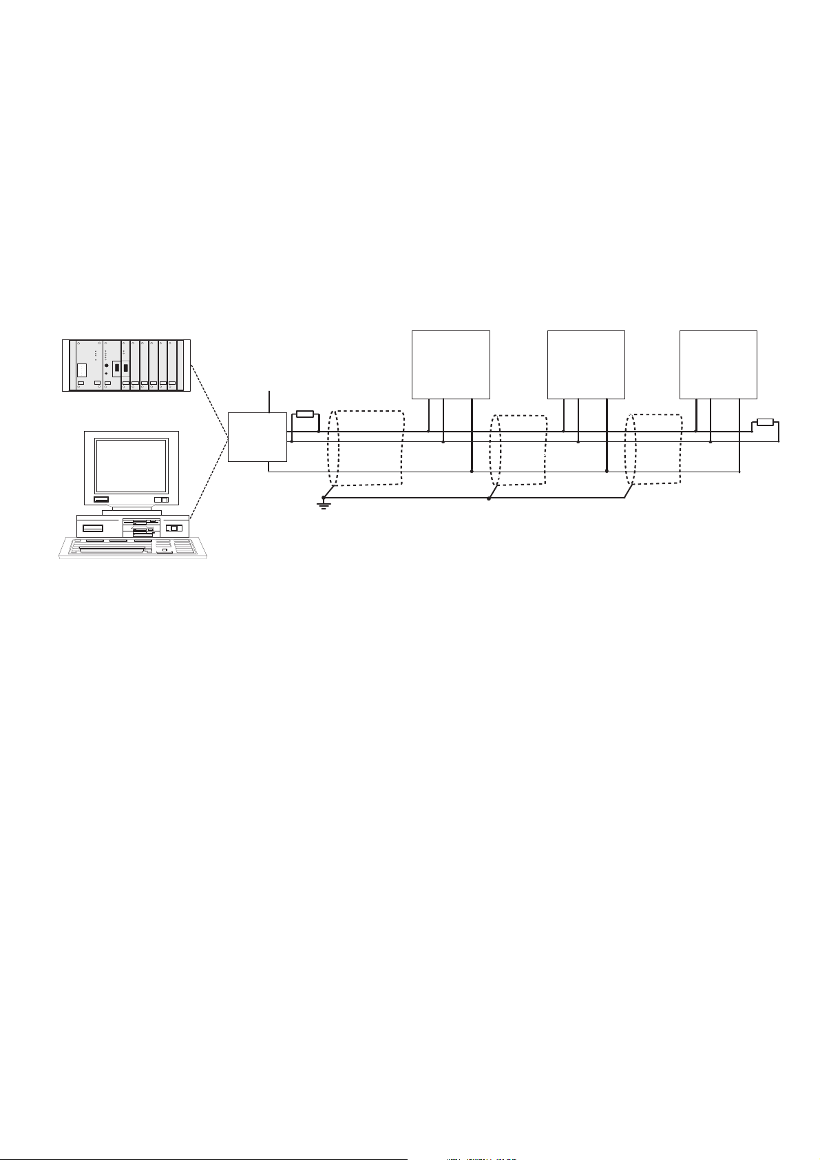
5.4. The RS 485 serial interface
5.4.1. General
With DVS drives, an RS 485 serial line can be used to transmit data over a twisted pair cable made of two symmetrical
twisted wires with a common shield. Maximum data transmission speed is 38.4 KBaud.
Transmission uses a standard differential RS 485 signal (half-duplex).
Up to a maximum of 32 DVS drives can be connected in Multidrop configurations.
The JP7 serial line jumper
The RS 485 serial line is supported by terminals 15, 16 and 17 on the DVS drive control card.
The differential signal is transmitted to terminal 16 and terminal 17. To prevent interference, termination resistors [100 Ohm]
must be fitted at the beginning and end of the RS 485 serial lines physical connection cables.
NOTA!
REGOLAZIONE
+V
CC
100W
RS232/
RS485
PE
Schermo collegato
da un solo lato
LINK +
LINK -
GND-D
When connecting and laying serial lines, make sure that the power cables are laid in separate
REGOLAZIONE REGOLAZIONE
100W
cable runways from the switchgear and relay cables.
Serial protocol
Serial protocol is set using the parameter I.600 [Serial link cfg], which provides a choice of the following protocols:
FoxLink proprietary protocol, Modbus RTU (default) and Jbus protocols.
The device address on the serial line is set using the parameter I.602 [ Device address].
See section 7.1 (INTERFACE /Serial Configuration) later in this manual for further details about data transmission parameters,
protocols, ranges and values. See chapter 8 later in this manual for instructions on the use of Modbus RTU communication
protocol with DVS drives.
User Manual Chapter 5 - Electrical Connections 29
Page 30
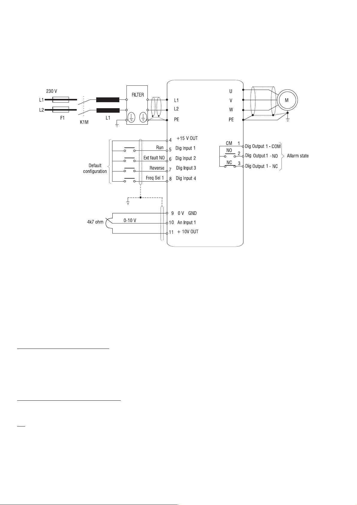
5.5. Typical Connection Schematics
5.5.1. DVS drive connections
Figure 5.5.1.1: Control via terminals, typical connection schematic
NOTA!
The control input connections shown above represent the most common connection solution for NPN
control. See below for further examples.
5.5.2. Design constraints
The wires for the analog signals must be shielded (connection to terminals 9, 10, 11).
The shielding must be connected to the PE terminal at only one side.
Grounding of the reference potential
The terminal wire shielding potential must normally be grounded. Jumper J7 links the potential of terminal 9 (GND 0V,
control reference) to protective earth (PE).
If a single installation comprises more than one drive, the different potentials of their terminal wire shields must be connected
in common to the control panels ground bus.
Direct connection to PLC inputs/outputs
Observe the following points if control commands or references are obtained directly from PLC inputs/outputs.
The PLCs 0V terminal must normally be grounded. if this is done, the drive control reference potential (J7 NOT fitted) must
not be grounded.
To ensure good immunity to interference, connect a 0.1mF 250V DC capacitor between terminal 9 and
ground. If more than one drive is present in a single installation, this must be done for each individual
drive.
30 Chapter 5 - Electrical Connections User Manual
Page 31

Drive relays
To ensure good immunity to interference, install RC filters in parallel with the coils of contactors connected to the drives
potential-free contacts.
5.5.3 Parallel mains AC input connections to more than one drive
Characteristics and limitations
- Drives installed in homogeneous groups must all be of the same model.
- All input chokes must be identical (same specifications and same supplier).
- All drives must receive power simultaneously. In other words they must all share the same switch/line contactor.
- No more than 6 drives must be connected in parallel to the same mains supply.
User Manual Chapter 5 - Electrical Connections 31
Page 32
5.7. Chokes and filters
NOTA!
NOTA!
A choke can be fitted to the mains input to DVS drives to limit RMS input current. Inductance can be
provided either by a single phase choke or by a mains transformer.
Contact your nearest TDE office for information on the use of sinusoidal output filters.
5.7.1. Mains input chokes
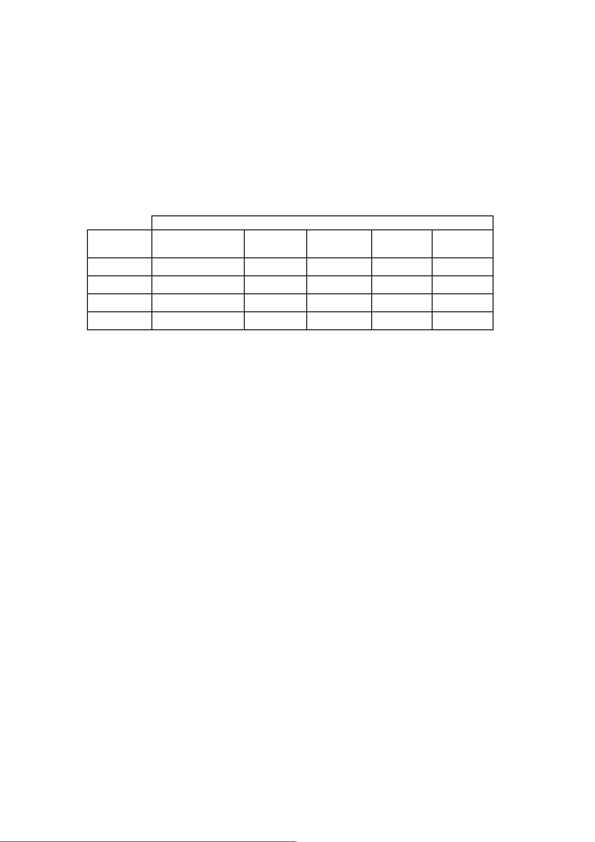
Table 5.7.1.1: Mains input chokes
Induttanza di rete monofase
Drive Tipo Induttanza di rete Corrente Corrente Frequenza Modello
[mH] Nom. [A] Saturaz. [A] [Hz]
025
037
055
075
Use of a mains choke is recommended for all drive models:
- to extend the life of the intermediate circuit capacitors and improve the reliability of the input diodes;
- to reduce harmonic distortion in the mains;
- to reduce the problems caused by power feed from a low impedence line.
3,8 7,6 50 / 60
5,5 11 50 / 60
7,5 15 50 / 60
10 20 50 / 60
NOTA!
Determine the nominal current of chokes on the basis of the nominal current of the standard motors
whose power ratings are specified in table 3.3.2.1.
5.7.2. Output chokes
DVS drives can be used with general purpose motors as well as motors specifically designed for inverter control. Motors
designed for inverter control normally have better insulation to withstand PWM voltages.
The following are examples of applicable reference standards.
Motors designed for control by inverters do not require special inverter output filters. Standard motors on the other hand, especially
those with long cables (typically longer than 30 metres) may need a choke on the inverter output to keep the voltage wave form
within specified limits.
The nominal current of these chokes must be approximately 20% greater than that of the inverter itself to compensate for
additional losses caused by modulation of the output wave form.
NOTA!
At the drives nominal current and a frequency of 50 Hz, output chokes cause an output voltage drop of
about 2%.
32 Chapter 5 - Electrical Connections User Manual
Page 33
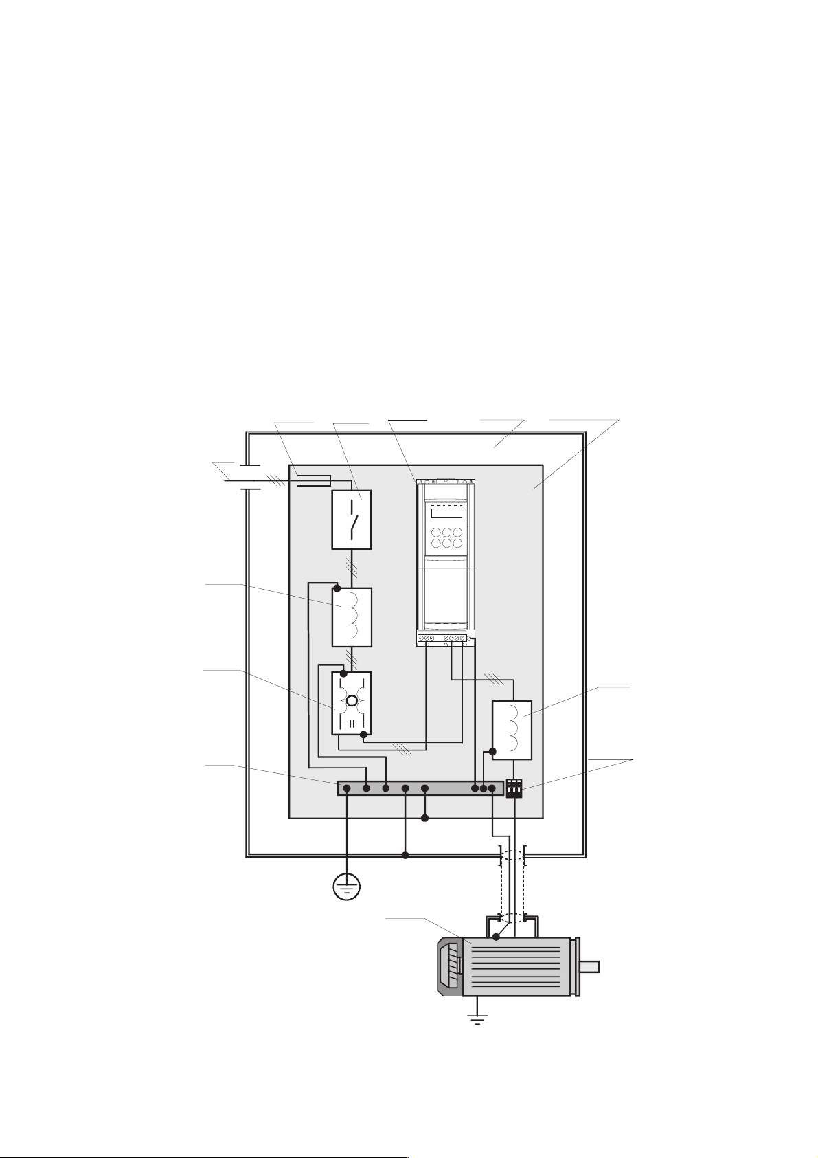
5.7.3. Noise filters
DVS drives are fitted with an EMI filter to limit radio frequency interference that could affect the mains.
Consult the Electro-Magnetic Compatibility Guide for further information on the subject of noise filters.
You can request a copy of the Electro-Magnetic Compatibility Guide from your nearest TDE office.
The Guide lists the power and control panel installation standards that must be followed to ensure EMC conformity according
to Directive 89/336/EEC. (These standards cover the installation, whenever necessary, of external filters and mains chokes,
cable shielding, ground connections, etc..)
The Guide also explains the background to EMC standards and lists the various conformity tests performed on TDE equipment.
5.7.3.1 External EMI filter connections
AC
Power
Supply
AC
Mains
choke
EMI filter
Ground
Bus
AC fuses
AC Mains
Contactor
AC Drive
U1 V1 W1
U2V2 W2 PE2 PE1
Cabinet
Mounting panel
Output
reactor
Motor
cable
terminals
AC Motor
User Manual Chapter 5 - Electrical Connections 33
Page 34
5.8. Braking
M
3
~
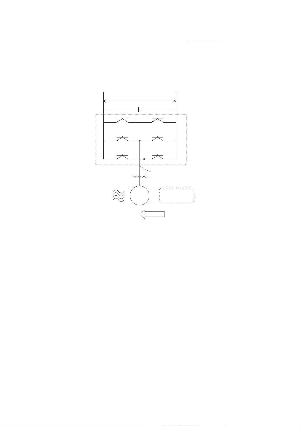
DVS drives provide DC braking as a standard function. The DC braking function applies a DC current to two of the motor
phases to generate braking torque. The machines kinetic energy is dissipated inside the motor in the form of heat.
The DC braking function cannot provide intermediate braking [e.g. rapid braking from 1400 to 1200 rpm],
but only braking to zero speed from already low speeds. If required, braking current can be measured
from phase U.
-+
U
DC
Inverter
UV W
/2
Energy Machine
M
3~
Energy
Figure 5.8.7: Principle of functioning of DC braking
5.9. Safety delay before work on the drive
After disconnecting a DVS drive from the mains supply, always respect a minimum delay of 60 seconds before starting any
work on its internal parts.
34 Chapter 5 - Electrical Connections User Manual
Page 35
Chapter 6 - Using the Drives Control Keys
This chapter tells you how to use the drives front panel control keys to set drive parameters.
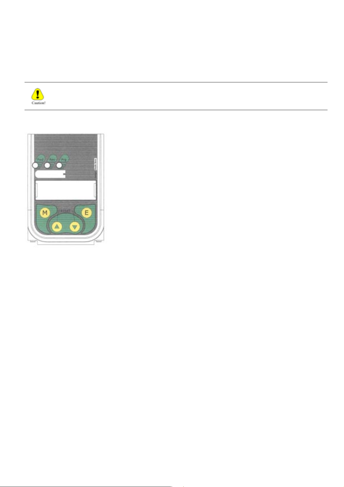
6.1 Control keys and LEDs
Though changes to parameter values are immediately effective, they are not automatically saved. A
specific command, the "C.000 [Save parameters] command must be used to save changes.
M Menu scroll key: Press to scroll from one parameter menu to the next (d.xxx,
S.xxx, I.xxx, F.xxx, P.xxx, A.xxx and C.xxx).
E Enter key: Press to access a parameter and/or confirm its value.
▲ UP key: Press to scroll up through a list of parameters and/or to increment
the value displayed. Also increments the motor potentiometer
reference in the "F.000 - Motorpot ref" parameter (F: FREQ &
RAMPS menu).
▼ DOWN key: Press to scroll down through a list of parameters and/or decrement
the value displayed. Also decrements the motor potentiometer
reference in the "F.000 - Motorpot ref" parameter (F: FREQ &
RAMPS menu).
▲ + ▼ UP + DOWN keys: Press simultaneously to reset the drive.
Interpretation of LEDs:
POWER-PRG (Yellow LED): Lit = inverter powered on. Flashing = parameter change not yet saved.
RUN (Green LED): Lit = motor running, Run command enabled and active*.
ALARM (R e d LED) : Lit = Drive a larm sta te.
(*) NOTE: The green LED flashes to indicate the the motor stall prevention function is active.
User Manual Chapter 6 - Using the Drives Control Keys 35
Page 36
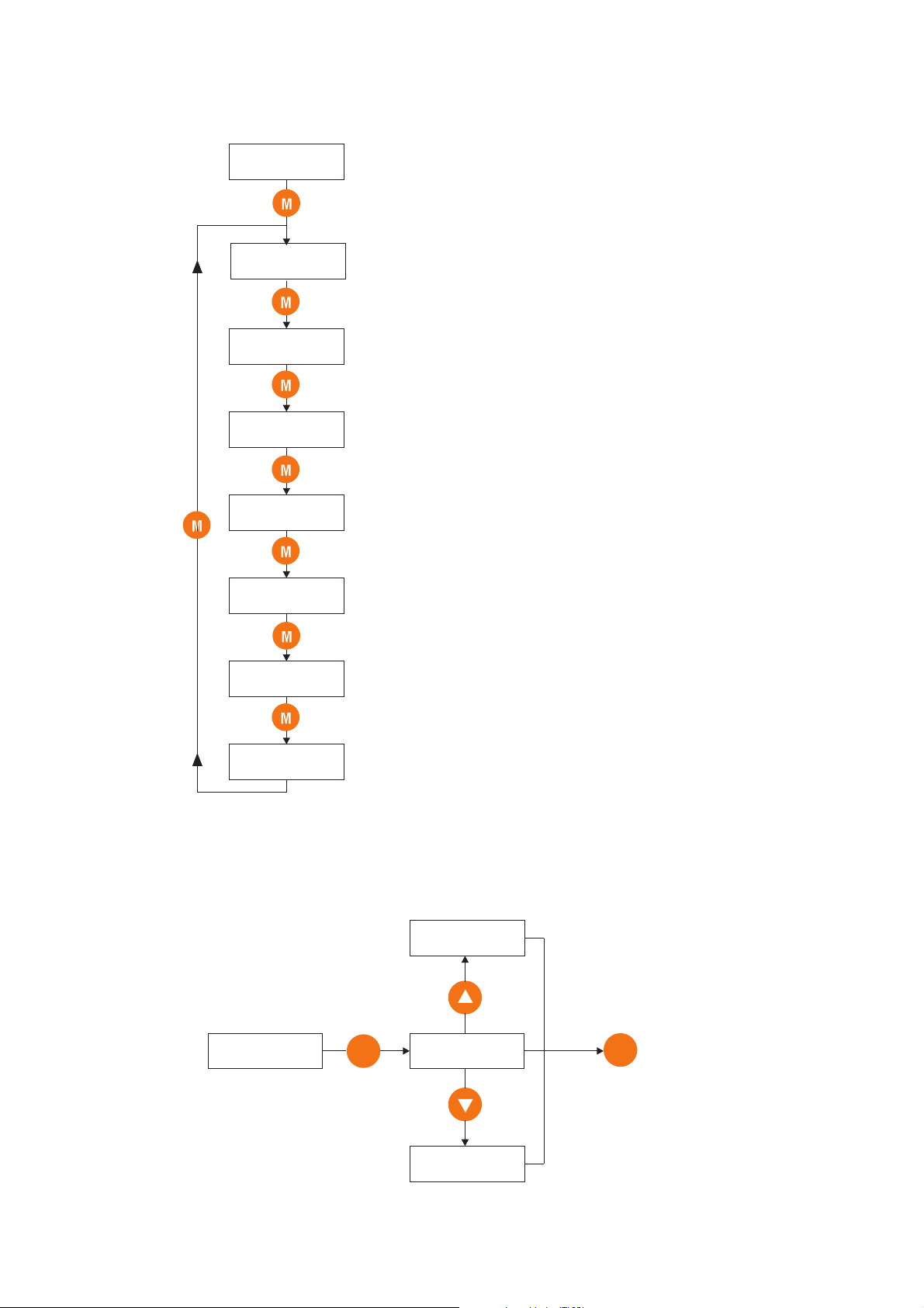
6.2 Navigating the menus
When the drive is powered on, the display automatically shows parameter d.000 [Output frequency] in the DISPLAY
menu.
0.0 Hz
d000
S000
I000
F000
-
P000
Output frequency
Menu of read-only parameters (display)
Menu of basic drive start up parameters
Menu of input/output drive settings (digital/analog)
Menu of multi frequencies and ramps settings
Menu of read/write drive parameters
A000
C000
Menu of PID function settings
Menu of control-type parameters (Save, Load default, etc.)
Example: how to change a frequency reference (FREQ & RAMP menu).
10.0 Hz
Increase
Frequency ref 0
F100
E
0.0 Hz
Decrease
E
To confirm
new setting
desired
- 200 Hz
36 Chapter 6 - Using the Drives Control Keys User Manual
Page 37
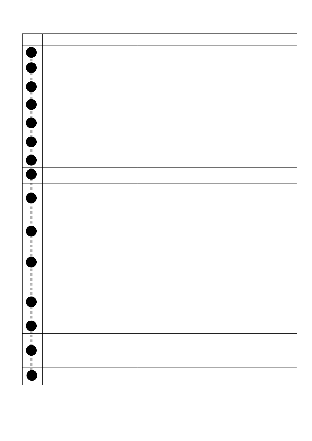
6.5 Quick setup
Step
!
"
#
$
%
&
Setup sequence
Go to the S - Startup menu
Set drive mains voltage
Set drive mains frequency
Set maximum drive output voltage
Set nominal frequency of motor
Set nominal current of motor
Set number of motor terminal pairs
Set the power factor of the motor
What to do
Press the "M" key to access the Startup menu.
Got to parameter S.000 and enter the drives mains voltage: 220V
or 240V.
Go to parameter S.001 and enter the drives mains frequency: 50Hz
or 60Hz.
Go to parameter S.100 and enter the maximum voltage the drive
can output to the motor (see data plate).
Go to parameter S.101 and enter the nominal frequency of the
motor (see date plate).
Go to parameter S.150 and enter the nominal current of the motor
(seedata plate).
Go to parameter S.151 and enter the number of motor terminal
pairs (terminals/2).
Go to parameter S.152 and enter the motors power factor (cos phi)
(see data plate).
'
!
"
Set control mode
Set the maximum reference frequency
Set the reference source
Set drive acceleration and deceleration
ramp times
Set % manual voltage boost
Auto-calibrate motor stator resistance
Go to parameter S.200 and enter the drives control mode:
- selection [1] = START&STOP via terminals (default)
- selection [2] = START&STOP via serial line [see menu H]
Go to parameter S.201 and enter the maximum threshold for the
drives reference frequency (analog and/or digital).
Go to parameter S.202 and enter the source of the drives frequency
reference:
- selection [1] = Reference from analog input 1 (default)
- selection [3] = Digital reference from parameter S.203
NOTE! Go to parameter S.203 and enter the digital reference
frequency (if relevant).
Go to parameter S.300 and enter the acceleration ramp time
(default = 5 secs).
Go to parameter S.301 and enter the deceleration ramp time
(default = 5 secs).
Go to parameter S.400 and enter the % of manual low speed
voltage boost (if relevant)
Go to parameter S.900 and activate the procedure for auto-
calibrating motor stator resistance:
- activate the procedure with "do" + E
#
NOTA!
User Manual Chapter 6 - Using the Drives Control Keys 37
Save parameters
See section 7.3 later in this manual for further information on enabling the automatic voltage boost function (S.400)
and setting motor slip compensation (S.450 & S.451), .
Go to the parameter S.901 and activate the procedure for saving
parameters in the drives non-volatile memory.
Page 38

Chapter 7 - Parameter Description
7.1 Parameters List
Legend of drive menu contents.
Menu d - DISPLAY
Menu S - STARTUP
Menu I - INTERFACE
Menu F - FREQ & RAMP
Menu P - PARAMETER
Menu A - APPLICATION
Menu C - COMMAND
Menu H - HIDDEN
NOTE!
In this chapter are described the functions of each drive parameter.
Anyway, the chapter 7 reports the description of the code and the name of each single parameter.
Menu of read-only parameters (display)
Menu for basic drive start up
Menu of input/output settings (digital/analog)
Menu of multi frequencies and ramps settings
Menu for drive regulation and optimization
Menu for PID function settings
Menu of control-type parameters (Save, Load default, etc.)
Menu not available on the keypad. It is reserved to set the drive parameters
through Serial line and/or through Field bus cards.
38 Chapter 7 - Parameters Description User Manual
Page 39
CODE: Parameter Code, showed on display.
Format = X.YYY:
X = Menu d=DISPLAY
S=STARTUP
I=INTERFACE
F=FREQ & RAMPS
P=PARAMETER
A=APPLICATION
C=COMMAND
H=HIDDEN
YYY = Parameter number
showed on display
Figure 7.1: Parameters Description Legend
[CODE]: PICK LIST CODE [IN BRAKET ]NAME: Parameter name,
Parameter default value
Parameter minimum value
Parameter maximum value
Parameter unit of measure
Parameter step of variation
Parameter sw number, used via serial
CODE NAME
S.MENU
S.000
Mains voltage
POWER SUPPLY
S.001
Mains frequency
NOTE!
PARAMETER PICK LIST
DESCRIPTION
[CODE]
FUNCTION
DESCRIPTION
MIN
DEFAULT
MAX
UNIT
START-UP
Rated value of the line
voltage
Rated value of the line
frequency
(ALIAS): On STARTUP menu only. Parameter code of same parameter on other menu .
(*): Parameter value dependent of the drive size.
(**): Parameter value dependent of the drive nominal main voltage and main frequency.
(***): Value dependent of the setting of another parameter.
(****): Value dependent of the drive type: 230 ....
110
220
230
240
50
60
110V
220V
230V
240V
50Hz
60Hz
230
(****)
110
(****)
240
(****)VHz
VARIATION
IPA
404
(P.020)
405
(P.021)
(ALIAS)
User Manual Chapter 7 - Parameters Description 39
Page 40
CODE NAME
d.000
Output frequency
d.001
Frequency ref
d.002
Output current
d.003
Output voltage
d.004
DC link voltage
d.005
Basic
Power factor
d.006
Power [kW]
d.007
Output speed
d.008
Speed ref
d.008
Estimate speed
d.050
Heatsink temp
PARAMETER PICK LIST
DESCRIPTION
[CODE]
FUNCTION
DISPLAY
Drive output frequency
Drive frequency reference
Drive output current (rms)
Drive output voltage (rms)
DC Bus drive voltage (DC)
Power factor
Power
Drive output speed
(d.000)*(P.600)
Drive speed reference
(d.001)*(P.600)
Estimated drive speed
Drive heatsink temperature
(linear sensor measured)
DESCRIPTION
MIN
MAX
Hz
Hz
A
V
V
kW
Hz
°C
UNIT
0.01
0.01
0.1
0.01
0.01
0.01/1
0.01/1
0.01/1
DEFAULT
IPA
VARIATION
001
002
003
1
004
1
005
006
007
008
009
062
1
010
d.051
OverloadInput/Output
Drive OL
d.052
Motor OL
d.100
Dig inp status
d.101
Term inp status
d.102
Vir dig inp stat
d.150
Dig out status
d.151
Term dig out sta
d.152
Vir dig out stat
d.200
An in 1 cnf mon
Drive overload (100% =
alarm threshold)
Motor overload (100% =
alarm threshold)
Digital inputs acquired by
the drive (terminal or
virtual)
Digital inputs terminal of
the drive regulation board
Virtual digital inputs
received by drive serial link
or field bus card
Digital outputs executed by
the drive (terminal or
virtual)
Digital outputs terminal of
the drive regulation board
Virtual digital outputs
executed by drive serial
link or field bus card
Analog input 1 destination;
it shows where the signal
is programmed
[0] Null funct
[1] Freq ref 1
[2] Freq ref 2
[3] Bst lev fact
[4] OT lev fact
[5] Vred lev fac
[6] DCB lev fact
[7] RampExt fact
%
0.1
011
%
0.1
012
014
015
016
020
021
022
026
d.201
An in 1 monitor
d.202
An in 1 term
mon
d.400
PID reference
d.401
PID feedback
Analog input 1 output block
% value
Analog input 1 input block
% value
PID reference signal
PID feedback signal
%
%
0.1
0.1
027
028
041
042
40 Chapter 7 - Parameters Description User Manual
Page 41
CODE NAME
PID error
d.402
PID integr comp
d.403
PIDAlarm List
PID output
d.404
1st alarm-latest
d.800
2nd alarm
d.801
3rd alarm
d.802
4th alarm
d.803
Drive rated curr
d.950
SW version (1/2)
d.951
SW version (2/2)
d.952
Power ident
d.953
code
Param ident
d.954
code
PARAMETER PICK LIST
DESCRIPTION
PID error signal
PID integral component
PID output signal
Last alarm stored by the
drive alarm list
Second to last alarm
Third to last alarm
Fourth to last alarm
Drive rated current (it
depends on the drive size)
Software version - part 1
Software version - part 2
Reseved
Reseved
[CODE]
FUNCTION
DESCRIPTION
MIN
MAX
%
%
%
UNIT
0.1
0.1
0.1
0.1
0.01
0.01
DEFAULT
IPA
VARIATION
043
044
045
046
047
048
049
050
051
052
053
054
Regul ident
d.955
code
Drive Identification
Startup id code
d.956
Drive size
d.957
Display Test
d.999
Reseved
Reseved
Drive size code
Drive display test
055
056
057
099
User Manual Chapter 7 - Parameters Description 41
Page 42
CODE NAME
S.000
Mains voltage
PARAMETER PICK LIST
DESCRIPTION
[CODE]
FUNCTION
START-UP
Rated value of the line
voltage
110
220
110V
220V
DESCRIPTION
(****)
MIN
MAX
DEFAULT
(****)
(****)
UNIT
V
VARIATION
IPA
404
(P.020)
(ALIAS)
Power SupplyV/fMotor DataCommands & Referencies
S.001
Mains frequency
S.100
Max out voltage
S.101
Base frequency
S.150
Motor rated curr
S.151
Motor pole pairs
S.152
Motor power fact
S.153
Motor stator R
S.200
Cmd source sel
Rated value of the line
frequency
Maximum value of the
voltage applied to the motor
Rated frequency of the
motor
Rated current of the motor
Pole Pairs of the motor
Motor power factor
Measurement of the stator
resistance of the motor
Source of the START and
STOP commands
230
240
50
60
[1] Terminals
[2] Virtual
[3] H-command
[4] Control word
230V
240V
50Hz
60Hz
START & STOP via
terminal
Main command via Virtual
& Terminal setting
Main command via serial
line
Reserved
(****)
(**)
(**)
(*)
(*)
(*)
(*)
1
(****)
50
25
(*)
1
0.01
0
0
(****)
(**)
500
(*)
60
1
99.99
4
Hz
V
Hz
A
ohm
1
0.1
0.1
0.01
0.01
405
(P.021)
413
(P.061)
414
(P.062)
406
(P.040)
407
(P.041)
408
(P.042)
409
(P.043)
400
(P.000)
S.201
Max ref freq
S.202
Ref 1 channel
S.203
Frequency ref 0
S.300
Acc time 1
S.301
Dec time 1
S.400
Manual boost
[%]
S.401
Auto boost en
Maximum frequency
reference threshold
and / or digital reference
(both directions)
Source of the Reference 1
Digital speed reference
(F.100)
Acceleration ramp delay
time 1
Deceleration ramp delay
time 1
Manual boost at low
revolutions
Automatic boost function
enabling
[0] Null
[1] Analog inp 1
[2]
[3] Freq ref x
[4] Multispeed
[5] Motorpotent
[6]
[7]
[8]
[0] Disable
[1] Enable
Null
Analog input 1
Not used
Frequency reference
S.203 (F.100)
Multi frequencies
Motorpotientometer
reference
Not used
Not used
Not used
Automatic boost function
disabled
Automatic boost function
enabled
(****)
3
0
5
5
1
0
25
0
-S.201
1
(***)
1
(***)
0
0
500
7
S.201
999.9
(***)
999.9
(***)
25
1
Hz
sec
sec
% of
S.100
0.1
0.1
(***)
0.1
(***)
305
(F.020)
307
(F.050)
311
(F.100)
329
(F.201)
330
(F.202)
421
(P.120)
423
(P.122)
42 Chapter 7 - Parameters Description User Manual
Page 43
CODE NAME
S.450
Slip compensat
S.451
Functions
Slip comp filter
S.900
Measure stator R
Utility
S.901
Save parameters
PARAMETER PICK LIST
DESCRIPTION
[CODE]
FUNCTION
Slip compensation
It is the response time for
the reaction of the function
Motor tuning command
Confirm? NO
Confirm? YES
No action
Autotune command
execution
Save parameters
Confirm? NO
Confirm? YES
No action
Save parameters
command execution
DESCRIPTION
0.1
0.1
NO
NO
MIN
MAX
DEFAULT
0
10
0
10
NO
YES
NO
YES
UNIT
%
sec
0.1
VARIATION
IPA
419
(P.100)
420
(P.101)
806
(C.100)
800
(C.000)
(ALIAS)
User Manual Chapter 7 - Parameters Description 43
Page 44
CODE NAME
I.000
Dig input 1 cfg
Digital Inputs Commands of the Regulation Board
PARAMETER PICK LIST
DESCRIPTION
[CODE]
FUNCTION
INTERFACE
Digital Input 1 configuration
[0] None
[1] Run
[2] Reverse
[3] Ext Fault NO
[4] Ext Fault NC
[5] Alarm reset
[6] Jog
[7] Freq sel 1
[8] Freq sel 2
[9] Freq sel 3
[10] Freq sel 4
[11] Ramp sel 1
[12] Ramp sel 2
[13] Enable NO
[14] Enable NC
[15] DCBrake en
[16] DCBrake
[17] Autocapture
[18] Ramp enable
[19] Zero ref
[20] PID enable
[21] PID freeze
[22] PID gain sel
[23] Motorpot Up
[24] Motorpot Dn
[25] Reset Motorp
[26] Fast stop
[27] Zero freq
Not active
RUN command for the
motor START
Speed REVERSE
command
External fault with NO
(Normal Open) contact
External fault with NC
(Norm. Closed) contact
Alarm reset command
JOG frequency reference
enabling
Binary selection for
Multispeed
Binary selection for
Multispeed
Binary selection for
Multispeed
Binary selection for
Multispeed
Binary selection for
Multiramp
Binary selection for
Multiramp
Drive Enable with NC
(Norm. Closed) contact
Drive Enable with NO
(Normal Open) contact
Enabling of the DC
braking function
Command for execution
of DC braking
Execution of the flying
restart
Enabling / Disabling of
the Ramp block
Ramp to 0Hz & main
commands active
Enabling of the PID
regulation.
Enabling PID freeze
output signal.
Selection of the PID
regualtor gain.
Motorpotentiometer
reference increasing
Motorpotentiometer
reference decreasing
Reset of
Motorpotentiometer ref.
Emergency stop
Enabling output freq. to
zero.
DESCRIPTION
MIN
MAX
DEFAULT
1
0
27
UNIT
IPA
VARIATION
100
I.001
Dig input 2 cfg
I.002
Dig input 3 cfg
I.003
Dig input 4 cfg
I.004
Dig input 5 cfg
I.005
Dig input 6 cfg
I.006
Dig input 7 cfg
I.007
Dig input 8 cfg
Digital Input 2 configuration
Digital Input 3 configuration
Digital Input 4 configuration
Digital Input 5 configuration
Digital Input 6 configuration
Digital Input 7 configuration
Digital Input 8 configuration
As for I.000
As for I.000
As for I.000
As for I.000
As for I.000
As for I.000
As for I.000
Not available
Not available
Not available
Not available
3
0
27
2
0
27
7
0
27
0
0
27
101
102
103
104
44 Chapter 7 - Parameters Description User Manual
Page 45
PARAMETER PICK LIST
CODE NAME
I.100 Dig output 1 cfg Digital Output 1 configura-
DESCRIPTION
tion
[CODE]
FUNCTION
[0] Drive Ready
[1] Alarm state
[2] Not in alarm
[3] Motor running
[4] Motor stopped
DESCRIPTION
Drive ready to start
Positive logic for alarm
signalling
Negative logic for alarm
signalling
Run command active
Run command not active
and frequency = 0Hz
MIN
MAX
DEFAULT
0045 112
UNIT
IPA
VARIATION
Digital Output State Regulation Board
[5] REV rotation
[6] Steady state
[7] Ramping
[8] UV running
[9] Out trq>thr
[10] Current lim
[11] DC-link lim
[12] Limit active
[13] Autocapt run
[14] Reserved
[15] Neg pwrfact
[16] PID err ><
[17] PID err>thr
[18] PID err<thr
[19] PIDer><(inh)
[20] PIDerr>(inh)
[21] PIDerr<(inh)
[22]
Anti-clockwise rotation of
the motor.
Motor is running in steady
state.
Acceleration or
Deceleration Ramp on
progress.
Undervoltage detectetion
during motor running.
Output torque higher than
the value of P.241.
Current limit (during ramp
or at steady state).
DC Bus limit (during ramp
or at steady state).
General signalling of drive
limit condition.
Autocapture on progress.
Reserved.
Negative condition of the
power factor .
PID error is >A.058 &
<=A.059.
PID error is >A.058.
PID error is <=A.059.
PID error is >A.058 &
<=A.059 (see chapter 7.7).
PID error is >A.058 (see
chapter 7.7).
PID error is <=A.059 (see
chapter 7.7).
[23]
[24]
[25]
[26] Extern fault
[27] No ext fault
[28] Serial TO
[29] freq=thr1
[30] freq!=thr1
[31] freq>thr1
[32] freq<thr1
[33] freq=thr2
[34] freq!=thr2
[35] freq>thr2
[36] freq<thr2
[37] HS temp=thr
[38] HS temp!=thr
[39] HS temp>thr
Positive logic for Ext. fault
alarm signalling.
Negative logic for Extern.
fault alarm signalling.
Serial link communication
time out.
Output frequency = to
P.440 & P.441 values.
Output frequency ? of
P.440 & P.441 values.
Output frequency > than
P.440 & P.441 values.
Output frequency < than
P.440 & P.441 values.
Output frequency = to
P.442 & P.443 values.
Output frequency ? of
P.442 & P.443 values.
Output frequency > than
P.442 & P.443 values.
Output frequency < than
P.442 & P.443 values.
Heatsink temp = to P.480
& P.481 values.
Heatsink temp ? of P.480
& P.481 values.
Heatsink temp > than
User Manual Chapter 7 - Parameters Description 45
Page 46
CODE NAME
PARAMETER PICK LIST
DESCRIPTION
[CODE]
FUNCTION
P.480 & P.481 values.
[40] HS temp<thr
Heatsink temp < than
P.480 & P.481 values.
[41] Output freq
Frequency in synchronism with output
frequency.
[42] Out freq x 2
Frequency value x 2 in
synchronism with output
frequency.
[43]OutCoastThru
Coast thru stopping.
DESCRIPTION
MIN
MAX
DEFAULT
UNIT
IPA
VARIATION
I.101
I.200
I.201
I.202
I.203
I.204
I.205
Analog Input Regulation Board
I.400
I.420
I.600
Dig output 2 cfg
An in 1 Type
An in 1 offset
An in 1 gain
An in 1 minimum
An in 1 filter
An in 1 clip level
Inp by serial en
Out by serial en
Serial link cfg
Digital Output 2 configuration
Setting of the Analog Input
1 type reference
Analog Input 1 offset
Analog Input 1 gain
An Input 1 minimun value
Response time of the
signal reaction
Virtual Digital enabling
Virtual Digital Outputs
setting enabling
Serial line configuration
protocol & mode
[44]OutEmgStop
[45]
As for I.100
[1]0-10V/0-20mA
[2]4-20mA
[0] FoxLink 7E1
[1] FoxLink 701
[2] FoxLink 7N2
[3] FoxLink 8N1
[4] ModBus 8N1
[5] JBus 8N1
Emergency stop.
Not available
Unipolar 0-10V o 0-20mA
Unipolar 4-20mA
PROTOCOL
TYPE
DATA BIT
PARITY
FoxLink 7E1 7 Even 1
FoxLink 7O1 7 Odd 1
FoxLink 7N2 7 None 2
FoxLink 7O1 8 None 1
Modbus 8N1 8 None 1
Jbus 8N1 8 None 1
113
1
0.1
1
2
0
-99.9
99.9
1
-9.99
9.99
0
0
99.99
0.001
5
0
0
0
0
0
0.25
250
255
15
sec
118
119
120
121
122
181
145
147
STOP BIT
1
0
5
0.1
155
I.601
Serial link bps
Serial Line Config
Serial line baudrate
[0] 600 baud
[1] 1200 baud
[2] 2400 baud
[3] 4800 baud
[4] 9600 baud
[5] 19200 baud
[6] 38400 baud
600 baud rate
1200 baud rate
2400 baud rate
4800 baud rate
9600 baud rate
19200 baud rate
38400 baud rate
4
0
6
156
[7]
[8]
[9]
I.602
Device address
Serial line address of the
0
0
99
1
157
drive
I.603
Ser answer
delay
I.604
Serial timeout
Serial line answer delay
time
Serial line transmission
timeout
Drive NOT in alarm and
signal on a digital output
1
0
0
0
250
25
msec
sec
0.1
1
158
159
Drive IN alarm and signal
on a digital output
46 Chapter 7 - Parameters Description User Manual
Page 47
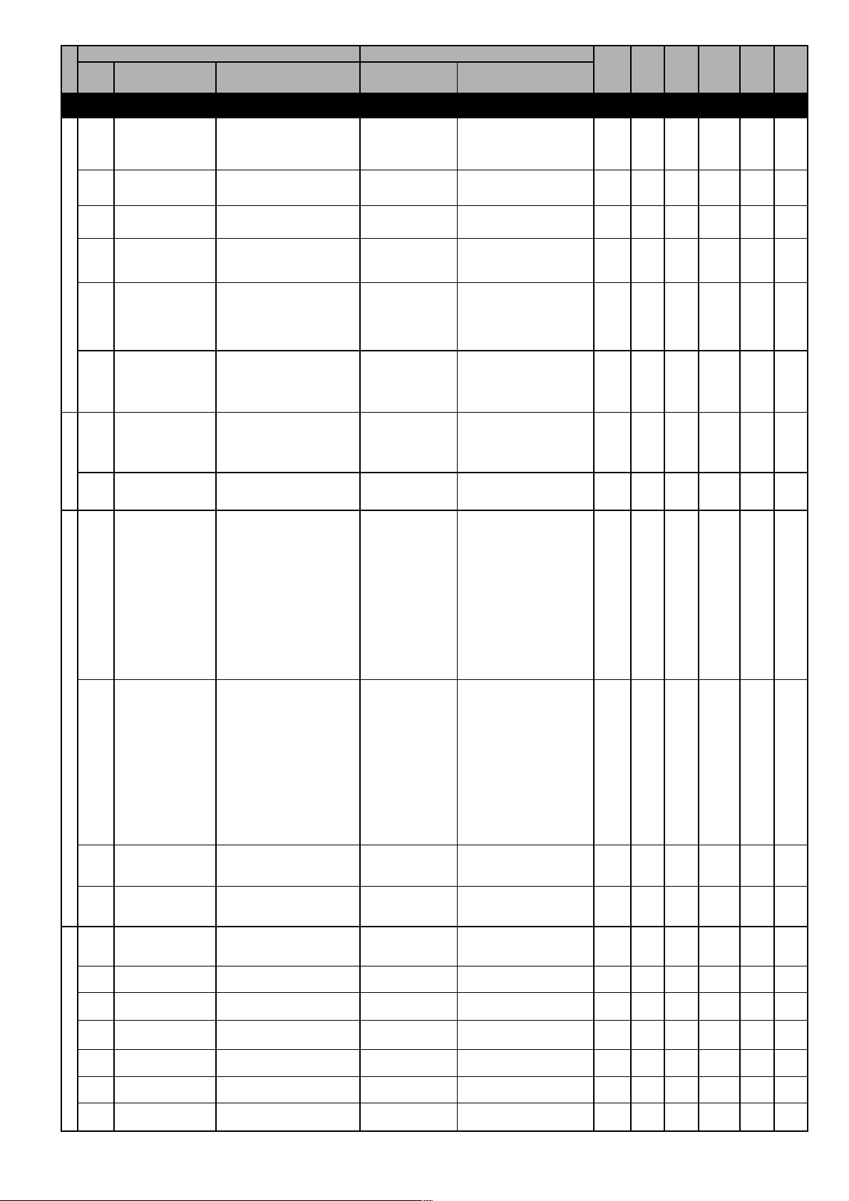
CODE NAME
F.000
Motorpot ref
F.001
Motorpot ref
unit
F.010
Acc/Dec time mp
F. 0 11
Motorpot offset
F.012
MotorpotentiometerReference Limit
Mp output mode
F.013
Mp auto save
F.020
Max ref freq
PARAMETER PICK LIST
DESCRIPTION
[CODE]
FUNCTION
FREQ & RAMP
Motopot reference (it can
be set using up and down
commands)
Unit of measure reference
Motorpot Accel. and Decel.
ramp time
Motopotentiometer
minimum reference
Unipolar / bipolar
Motorpotentiometer
Motopotenziometer auto
save function
Motor maximum frequency
value (for both the
directions)
[0] Unipolar
[1] Bipolar
[0] Disable
[1] Enable
Motorpotentiometer
unipolar
Motorpotentiometer
bipolar
Motorpot auto save
function disabled
Motorpot auto save
function enabled
DESCRIPTION
0
10
0
0
1
(****)
MIN
MAX
Hz
sec
Hz
Hz
UNIT
0.01
0.1
0.1
0.1
DEFAULT
0
F. 0 20
0.1
999.9
0
F. 02 0
0
1
0
1
25
500
IPA
VARIATION
300
343
301
302
303
304
305
F.021
F.050
F.051
Reference SourcesMulti Frequency Function
F.060
F.061
Min ref freq
Ref 1 channel
Ref 2 channel
MltFrq channel 1
MltFrq channel 2
Minimum frequency value
Source of the Reference 1
Source of the Reference 2
Source of the Multispeed 1
Source of the Multispeed 2
[0] Null
[1] Analog inp 1
[2]
[3] Freq ref x
[4] Multispeed
[5] Motorpotent
[6]
[7]
[8]
[0] Null
[1] Analog inp 1
[2]
[3] Freq ref x
[4] Multispeed
[5] Motorpotent
[6]
[7]
[8]
Null
Analog input 1
Not used
Frequency reference
F.100 (S.203)
Multi frequncies
Motorpotientometer
reference
Not used
Not used
Not used
Null
Analog input 1
Not used
Frequency reference
F.101
Multispeed
Motorpotientometer
reference
Not used
Not used
Not used
As for F.050, Reference 1
source
As for F.051, Reference 2
source
0
0
F. 02 0
3
0
0
0
3
0
3
0
Hz
5
8
8
8
0.1
306
307
308
309
310
F.100
Frequency ref 0
F.101
Frequency ref 1
F.102
Frequency ref 2
F.103
Frequency ref 3
F.104
Frequency ref 4
F.105
Frequency ref 5
F.106
Frequency ref 6
Digital Reference frequency 0
Digital Reference frequency 1
Digital Reference frequency 2
Digital Reference frequency 3
Digital Reference frequency 4
Digital Reference frequency 5
Digital Reference frequency 6
0
-F.020
F. 02 0
0
-F.020
F. 02 0
0
-F.020
F. 02 0
0
-F.020
F. 02 0
0
-F.020
F. 02 0
0
-F.020
F. 02 0
0
-F.020
F. 02 0
Hz
Hz
Hz
Hz
Hz
Hz
Hz
0.1
0.1
0.1
0.1
0.1
0.1
0.1
311
312
313
314
315
316
317
User Manual Chapter 7 - Parameters Description 47
Page 48
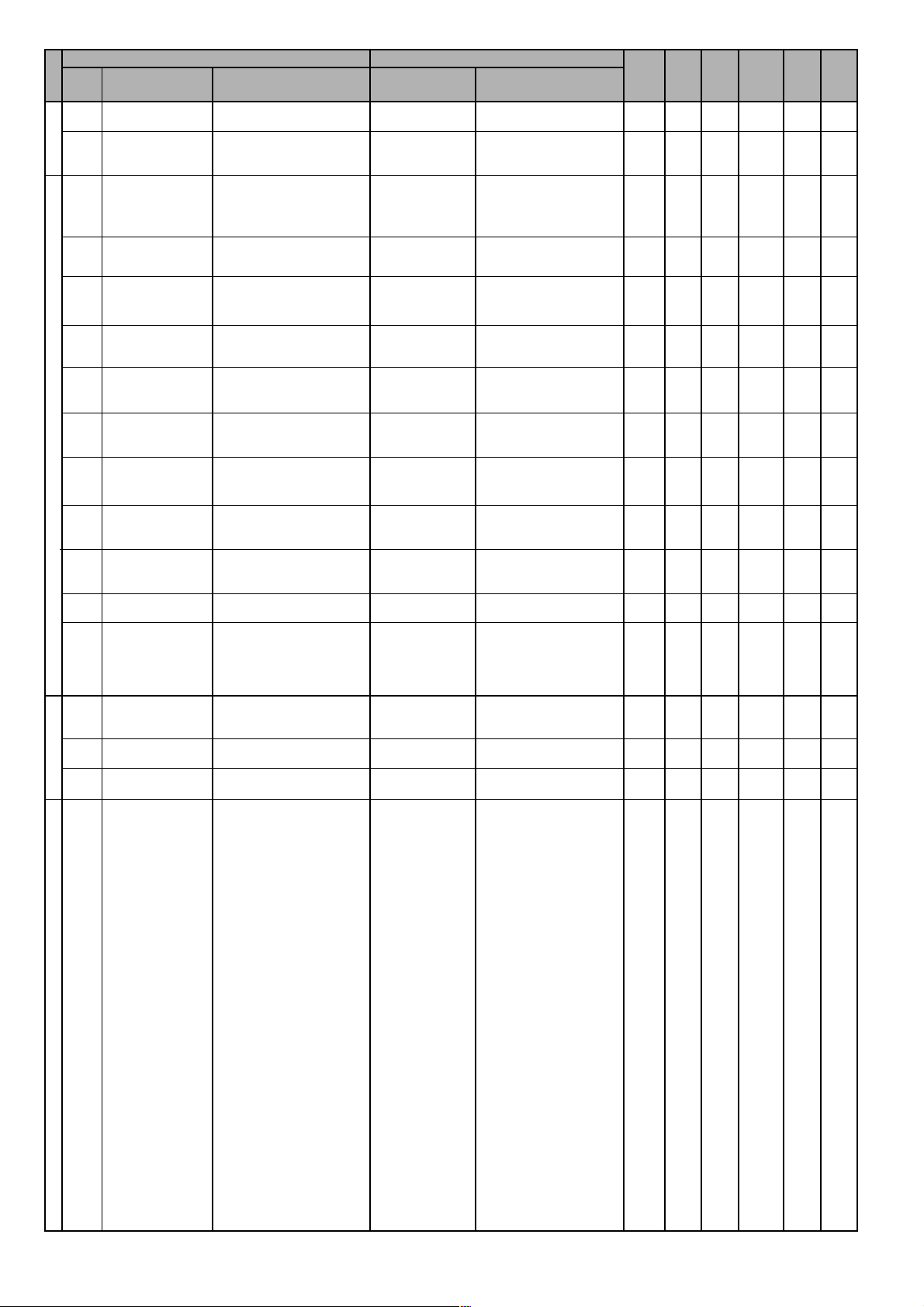
CODE NAME
F.107
Frequency ref 7
PARAMETER PICK LIST
DESCRIPTION
Digital Reference frequency 7
[CODE]
FUNCTION
DESCRIPTION
MIN
MAX
Hz
UNIT
0.1
DEFAULT
0
-F.020
F. 02 0
IPA
VARIATION
318
F. 11 6
Jog frequency
F.200
Ramp resolution
F.201
Acc time 1
F.202
Dec time 1
F.203
Acc time 2
F.204
Dec time 2
F.205
Acc time 3
F.206
Dec time 3 / FS
F.207
Acc time 4 / Jog
F.208
Dec time 4 / Jog
Jogging frequency
reference
Accuracy of the ramp
setting
Acceleration ramp time
delay 1
Deceleration ramp time
delay 1
Acceleration ramp time
delay 2
Deceleration ramp time
delay 2
Acceleration ramp time
delay 3
Deceleration ramp time
delay 3 / Fast Stop decel.
Accel. ramp time delay 4 /
Accel. time in jogging state
Decel. ramp time delay 4 /
Decel. time in jogging state
[0] 0.01s
[1] 0.1s
[2] 1s
From 0.01s to 99.99s
From 0.1s to 999.99s
From 1s to 9999s
0
-F.020
F. 02 0
-
1
0
5
0.1
999.9
(***)
5
0.1
999.9
(***)
5
0.1
999.9
(***)
5
0.1
999.9
(***)
5
0.1
999.9
(***)
5
0.1
999.9
(***)
5
0.1
999.9
(***)
5
0.1
999.9
(***)
2
(***)
(***)
(***)
(***)
(***)
(***)
(***)
(***)
Hz
sec
sec
sec
sec
sec
sec
sec
sec
0.1
0.1
(***)
0.1
(***)
0.1
(***)
0.1
(***)
0.1
(***)
0.1
(***)
0.1
(***)
0.1
(***)
327
328
329
330
331
332
333
334
335
336
F.250
Ramp S-shape
F.260
Ramp extens src
F.270
Jump amplitude
F.271
Jump frequency 1
F.272
Jump frequency 2
Jump frequency Ramp Config
S Ramp shaping
Source for the Ramp time
extension function
Jump frequencies
hysteresys
Jump frequency 1
Jump frequency 2
[0] Null
[1] Analog inp 1
[2]
[3]
Null
Analog input 1
0
0
10
sec
0.1
337
0
0
3
0
0
100
Hz
0
0
500
Hz
0
0
500
Hz
0.1
0.1
0.1
338
339
340
341
48 Chapter 7 - Parameters Description User Manual
Page 49
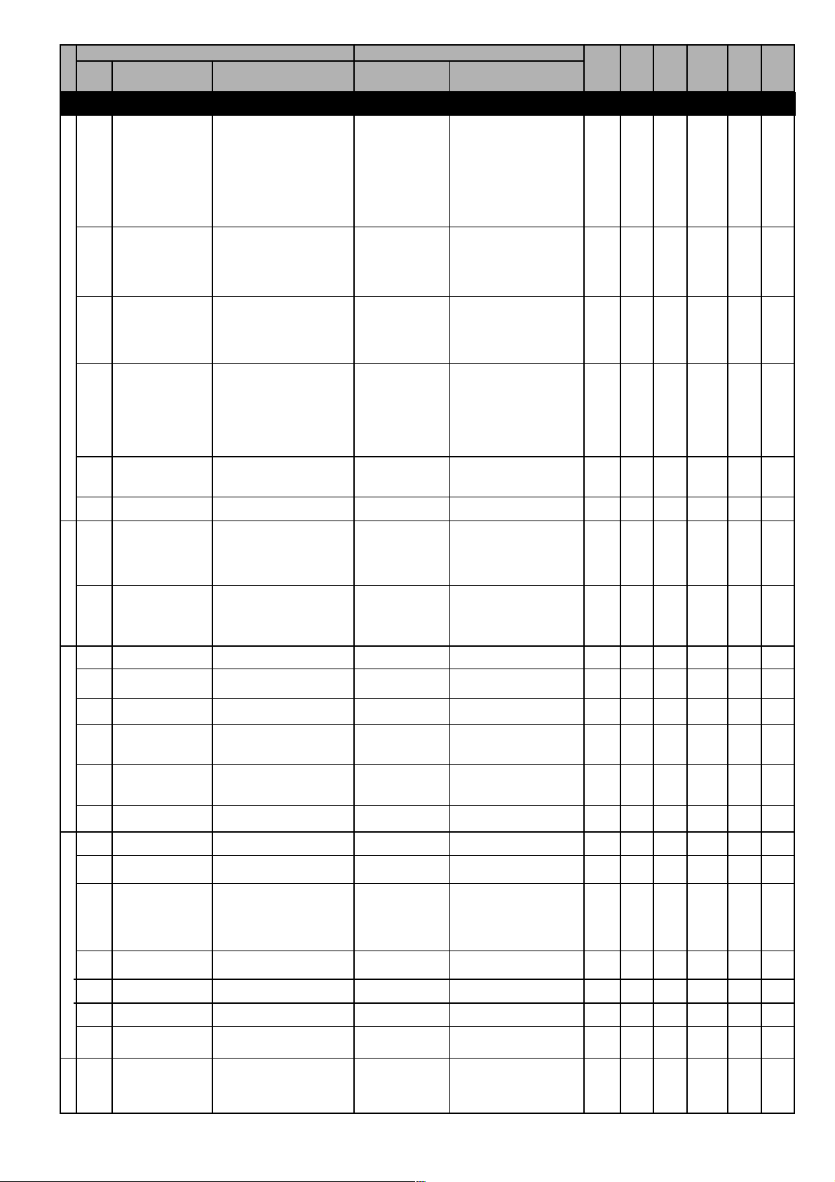
CODE NAME
P.000
Cmd source sel
P.001
RUN input config
P.002
Reversal enable
CommandsPower SupplyMotor DataV/F Curve
P.003
Safety
PARAMETER PICK LIST
DESCRIPTION
[CODE]
FUNCTION
PARAMETER
It defines the use of START
and STOP commands
Command logic
Reversal enabling
Safe start definition
[1] Terminals
[2] Virtual
[3] H-command
[4] Control word
[0] Run / Rev
[1] Fwd / Rev
[0] Disable
[1] Enable
[0] OFF
[1] ON
START & STOP via
terminal
Main command via Virtual
& Terminal setting
Main command via serial
line
Reserved
Disable negative rotation
of the motor.
Enable negative rotation
of the motor.
Disabling of the HW
reverse command
Enabling of the HW
reverse command
START allowed with RUN
temirnal connected at the
power on
START not allowed with
RUN temirnal connected
at the power on
DESCRIPTION
MIN
MAX
DEFAULT
1
1
4
0
0
1
1
0
1
1
0
1
UNIT
IPA
VARIATION
400
401
402
403
P.004
Stop mode
P.005
Deflt rot mode
P.020
Mains voltage
P.021
Mains frequency
P.040
Motor rated curr
P.041
Motor pole pairs
P.042
Motor power fact
P.043
Motor stator R
P.044
Motor cooling
P.045
Motor thermal K
P.046
Motor nom slip
P.047
Motor nom eff
Motor stop control function
Rated value of the line
voltage
Rated value of the line
voltage frequency
Rated current of the motor
Pole Pairs of the motor
Motor power factor
Measurement of the stator
resistance of the motor
Motor type cooling
Motor thermal constant
Motor nominal slip
Motor nominal efficency
[0] In ramp
[1] Ramp to
stop
110
220
230
240
50
60
[0] Natural
[1] Forced
Decel. ramp up to 0Hz.
Ramp to stop
110V,
220V,
230V,
240V,
50Hz
60Hz
Self ventilated
Assisted ventilation
0
(****)
(****)
(*)
(*)
(*)
(*)
0
30
(**)
(**)
0
(****)
(****)
(*)
1
0.01
0
0
1
0
50
1
(****)
(****)
(*)
60
1
99.99
1
120
250
100
V
Hz
A
ohm
min
%
%
0.1
0.01
0.01
493
502
404
405
406
407
408
409
410
411
501
504
P.060
V/f shape
P.061
Max out voltage
P.062
Base frequency
P.063
V/f interm volt
P.064
V/f interm freq
P.080
Max output freq
V/F Curve Type
Maximum output voltage
Base frequency
V/F intermediate voltage
V/F intermediate frequency
Maximum output frequency
[0] Custom
[1] Linear
[2] Quadratic
V/F curve defined by the
user
Linear characteristic
Quadratic characteristic
1
(**)
(**)
(**)
(**)
100
50
25
0
2
(**)
V
500
Hz
0
P. 0 6 1
1
P. 0 6 2
0
110
V
Hz
% of
F. 02 0
0.1
0.1
0.1
412
1
413
414
415
416
417
User Manual Chapter 7 - Parameters Description 49
Page 50
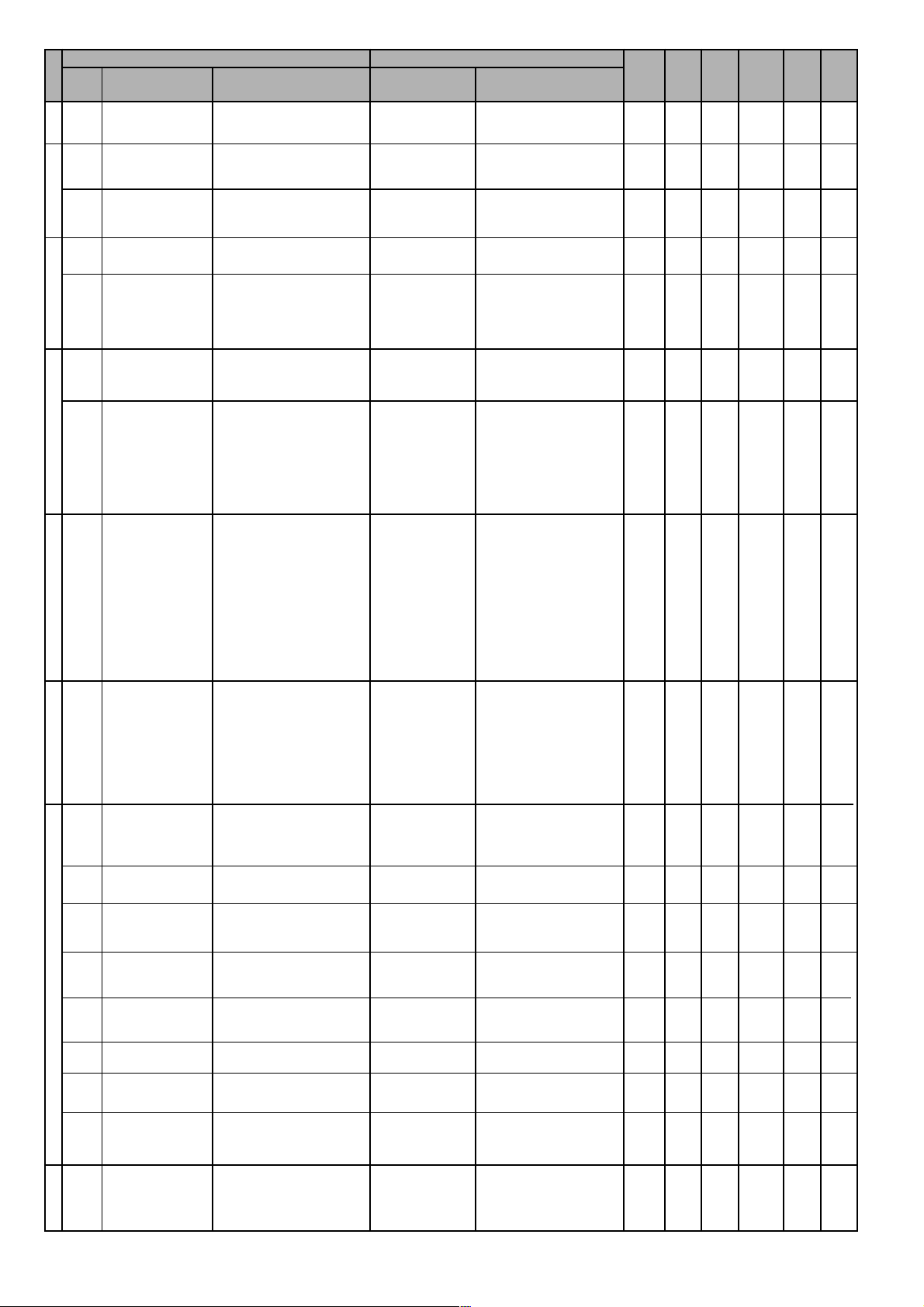
CODE NAME
P.081
Min output freq.
P.100
Slip compensat
P.101
P.120
BoostAutomatic Flux RegulationAnti Oscillation functionSW Curr. ClampCurrent Limit
P.121
P.122
P.140
Slip comp filter
Manual boost
[%]
Boost factor src
Auto boost en
Magn curr gain
Slip Comp.
PARAMETER PICK LIST
DESCRIPTION
Minimum output frequency
Slip compensation
Time constant of slip
compensation
Torque boost level
Boost level source
Automatic boost enabling
Magnetizing current
regulator gain
[CODE]
FUNCTION
[0] Null
[1] Analog inp 1
[2]
[3]
[0] Disable
[1] Enable
Null
Analog input 1
Not used
Not used
DESCRIPTION
0.0
0.1
MIN
MAX
% of
F. 02 0
%
sec
% of
P. 0 6 1
%
UNIT
0.1
0.1
0.1
DEFAULT
0.0
25.0
0
0
250
0
10
1
0
25
0
0
3
1
0
1
0
0
100
IPA
VARIATION
418
419
420
421
422
423
424
P.160
Osc damping
gain
P.180
SW clamp enable
P.200
En lim in ramp
P.201
Curr lim in ramp
P.202
En lim in steady
P.203
Curr lim steady
Damping gain
Current clamp enable
Enable current limitation
during ramp
Current limit in ramp
Enable current limitation in
steady state
Current limit at constant
speed
[0] Disable
[1] Enable
[0] None
[1] PI Limiter
[2] Ramp freeze
[0] Disable
[1] Enable
0
1
0
170
0
170
20
20
0
100
0
1
0
2
170
0
1
% I
nom
170
425
426
427
428
429
430
P.204
Curr ctrl P-gain
P.205
Curr ctrl I-gain
P.206
Curr ctr feedfwd
P.207
Curr lim dec
ramp
Current limiter proportional
gain
Current limiter integral gain
Current limiter feedforward
Current limiter deceleration
ramp
30.0
10.0
0
170
0.1
0.1
0
20
100
100
250
200
% of I
nom
%
% of I
nom
0.1
0.1
431
432
433
494
50 Chapter 7 - Parameters Description User Manual
Page 51
CODE NAME
P.220
En DC link ctrl
P.221
DC-lnk ctr Pgain
P.222
DC Link LimitOver Torque Alarm ConfigMotor Overload ConfigDC Brake Config
DC-lnk ctr Igain
P.223
DC-link ctr FF
P.240
OverTorque
mode
P.241
OT curr lim thr
PARAMETER PICK LIST
DESCRIPTION
Stall prevention during dec.
for overvoltage
DC link voltage limiter
proportional gain
DC link voltage limiter
integral gain
DC link voltage limiter feedforward
Overtorque mode
Current limit for overtorque
[CODE]
FUNCTION
[0] None
[1] PI Limiter
[2] Ramp freeze
[0] No Alm,Chk
on
[1] No Alm,Chk
ss
[2] Alm always
[3] Alm steady
st
0: Overtorque detection
always active and Overtorque alarm disabled.
1: Overtorque detection in
steady state and Overtorque alarm disabled.
2: Overtorque detection
always active and Overtorque alarm enabled.
3: Overtorque detection in
steady state and Overtorque alarm enabled.
DESCRIPTION
0
20.0
2.0
0
0
110
MIN
MAX
DEFAULT
0
2
0.1
100
0.1
100
0
250
0
3
20
200
UNIT
%
%
0.1
%
0.1
%
%
%
IPA
VARIATION
434
435
436
437
438
439
P.242
OT level fac src
P.243
OT signal delay
P.260
Motor OL prot
en
P.300
DC braking level
P.301
DCB lev fac src
P.302
DC braking freq
P.303
DC braking start
P.304
DC braking stop
Overtorque level factor
source
Delay time for overtorque
signaling
Enabling of motor overload
protection
DC braking level
DC braking level factor
source
Frequency for DC braking
enabling
DC braking time at start
DC braking time at stop
[0] Null
[1] Analog inp 1
[2]
[3]
[0] Disable
[1] Enable
[0] Null
[1] Analog inp 1
Null
Analog input 1
Not used
Not used
Null
Analog input 1
0.1
0
0
3
0.1
25
sec
1
0
1
0
0
100
% of I
nom
0
0
1
0
0
500
Hz
0
0
60
sec
0
0
60
sec
0.1
0.01
440
441
444
449
450
451
452
453
P.320
Autocapture
mode
P.321
Autocapture Ilim
P.322
Demagnetiz time
P.323
Autocap f scan t
Flying restart mode
Catch on flight current limit
Demagnetization minimun
time
Frequency scanning time
during Pick Up
[0] Disable
[1] 1st run only
[2] Always
Null
Flying restar at power on
Flying restart at run
command
0
120
1
1
0
20
0.01
0.1
2
170
10
25
% of I
nom
sec
sec
0.1
0.1
0.1
454
456
457
458
User Manual Chapter 7 - Parameters Description 51
Page 52
CODE NAME
P.324
Autocap V scan t
P.325
Autocap spd src
Autocapture function
P.340
Undervoltage thr
P.341
Max pwrloss time
P.342
UV alarm storage
P.343
Undervoltage Config
UV Trip mode
P.360
OV prevention
PARAMETER PICK LIST
DESCRIPTION
Voltage scanning time
during Pick Up
Source of the reference for
Pick Up function
Undervoltage threshold
Restart time from
undervoltage
Enabling of undervoltage
alarm storage
Undervoltage tripping mode
Automatic PickUp enabling
after Overvoltage
[CODE]
FUNCTION
[0] Frequency ref
[1] Max freq ref
[2] Last freq ref
[3] Encoder
[0] Disable
[1] Enable
[0] Disabled
[1] CoastThrough
[2] Emg stop
[0] Disable
[1] Enable
From active frequency
reference
From the Max fre ref
parameter
From freq. set desired
From encoder
Function disabled
Coast Through mode
Emergency stop mode
DESCRIPTION
0.2
MIN
MAX
V
% of
P. 06 1
sec
UNIT
0.1
DEFAULT
0.1
25
0
0
3
0
40
80
0
0
25
1
0
1
0
0
2
1
0
1
IPA
VARIATION
459
460
462
463
464
491
465
Overvol. Config
P.380
P.381
P.382
P.383
Autoreset Config
P.400
External Fault ConfigVoltage Reductuction Config
Autoreset
attmps
Autoreset clear
Autoreset delay
Autores flt rly
Ext fault mode
Number of autoreset
attempts
En. automatic reset of
autorestart attempts
Autoreset time delay
Alarm relay contacts
behaviour during autoreset
External fault mode
[0] OFF
[1] ON
[0] Alm alw,No AR
[1] Alm run,No AR
[2] Alm alw, ARes
[3] Alm run,
ARes
- Drive in alarm
Alarm always active
Alarm autoreset is not
possible.
- Drive in alarm
Alarm active only with
running motor.
Alarm autoreset is not
possible.
- Drive in alarm
Alarm always active
Alarm autoreset is
possible.
- Drive in alarm
Alarm active only with
running motor
Alarm autoreset is
possible.
10
0
0
255
0
5
0.1
1
0
0
0
250
50
1
3
min
sec
466
467
468
469
470
0.1
P.410
Ph Loss detec
en
P.420
Volt reduc mode
P.421
V reduction fact
P.422
V fact mult src
Phase Loss detection
enabling
Voltage reduction mode
Output voltage reduction
factor
Source of voltage
reduction factor multiplier
[0] Disable
[1] Enable
[0] Always
[1] Steady state
[0] Null
[1] Analog inp 1
[2] Analog inp 2
[3] Analog inp 3
Always
Costant speed only
Null
Analog input 1
Analog input 2
Analog input 3
1
0
100
0
10
0
1
0
1
% of
100
P. 06 1
0
3
492
471
472
473
52 Chapter 7 - Parameters Description User Manual
Page 53
CODE NAME
P.440
Frequency prog 1
P.441
Freq prog 1 hyst
P.442
Frequency prog 2
P.443
Freq prog 2 hyst
Frequency Threshold
P.460
Const speed tol
P.461
Const speed dly
Steady State
P.480
Heatsnk temp
lev
P.481
Heatsnk temp
hys
Heatsink Temp.PWM Settings
P.500
Switching freq
PARAMETER PICK LIST
DESCRIPTION
Frequency 1 level detection
Hysteresis amplitude
related to P-420
Frequency 2 level detection
Hysteresis amplitude
related to P-422
Tolerance at constant
speed
Ramp end signalling delay
Heatsink temperature
signalling level
Hysteresis band related to
P. 4 8 0
Modulation frequency
[CODE]
FUNCTION
[0] 1kHz
[1] 2kHz
[2] 3kHz
[3] 4kHz
[4] 6kHz
[5] 8kHz
[6] 10kHz
[7] 12kHz
[8] 14kHz
[9] 16kHz
[10] 18kHz
DESCRIPTION
0.5
0.5
0.5
0.2
70
(*)
MIN
MAX
Hz
Hz
Hz
Hz
Hz
sec
°C
%#
UNIT
0.1
0.1
0.1
0.1
DEFAULT
0
0
50
0
50
0
0
50
0
50
0
25
0
25
10
110
5
0
10
0
10
IPA
VARIATION
474
475
476
477
478
479
480
481
482
P.501
Sw freq reduc
en
P.520
Overmod max
lev
P.540
Out Vlt auto adj
P.560
Deadtime cmp
lev
P.561
Deadtime cmp
slp
Dead Time Comp.Display SettingsProtection
P.580
Startup display
P.600
Speed dsply fact
P.999
Param prot code
Enabling of switching
frequency reduction under
5Hz
Overmodulation level
Automatic adjustment of
output voltage
Dead times compensation
limit
Dead times compensation
slope
Display IPA at start up
Speed conversion constant
for display
Parameters protection code
[0] Disable
[1] Enable
[0] Disable
[1] Enable
0 : All parameters are not
protected
1 : Parameters
F.100F.116 are not
protected; protected
the others.
2 : All parameters are
protected.
3 : All parameters are not
protected; storage
allowed while motor
running. NOT
RECOMMENDED.
(*)
(*)
0
0
1
0
0
100
%
1
0
1
0
255
0
255
1
1
1999
1
0.01
99.99
0
0
3
483
484
485
486
487
488
489
490
User Manual Chapter 7 - Parameters Description 53
Page 54
CODE NAME
A.000
PID mode
A.001
PID ref sel
PARAMETER PICK LIST
DESCRIPTION
[CODE]
FUNCTION
APPLICATION
PID mode
PID reference selector
[0] Disable
[1] Freq sum
[2] Freq direct
[3] Volt sum
[4] Volt direct
[5] Stand alone
[6] St-Al always
[0] Null
[1] Analog inp 1
[2] Analog inp 2
[3] Analog inp 3
[4] Frequency ref
[5] Ramp output
[6] Digital ref
[7] Encoder freq
Null
PID out in sum with ramp
out ref (Feed forward)
PID out not in sum with
ramp out ref (no Feed
forward)
PID out not in sum with
voltage ref (no Feed
forward)
PID out not in sum with
voltage ref (no Feed
forward)
PID function as generic
control (only with drive in
RUN)
PID function as generic
control (any drive status)
Null
Analog input 1
Analog input 2
Analog input 3
Frequency reference
Ramp output
Internal reference
Encoder frequency
DESCRIPTION
MIN
MAX
DEFAULT
0
0
6
0
0
7
UNIT
IPA
VARIATION
1200
1201
A.002
PID fbk sel
PID Settings
A.003
PID digital ref
A.004
PID activat mode
A.005
PID-Encoder sync
A.006
PID err sign rev
A.007
PIDInteg init en
A.008
PID update time
A.050
PID Prop gain 1
A.051
PID Int tconst 1
A.052
PID Deriv gain 1
PID feedback selector
PID digital reference
PID active in steady state
only
Enabling of encoder / PID
synchronism
Error sign reversal
Integral term initialization at
start
PID updating time
Proportional term gain 1
Integral action time 1
Derivative action time 1
[0] Null
[1] Analog inp 1
[2] Analog inp 2
[3] Analog inp 3
[4] Encoder freq
[5] Output curr
[6] Output torque
[7] Output power
[0] Always
[1] Steady state
[0] Disable
[1] Enable
[0] Disable
[1] Enable
[0] Disable
[1] Enable
Null
Analog input 1
Analog input 2
Analog input 3
Encoder frequency
Output peak current
Output torque
Output power
0
0
0
0
0
0
0
0
99.99
0
0
-
-100
0
0
0
0
0
0
0
0
7
100
1
1
1
1
2.5
99.99
99.99
99.99
%
sec
0.1
0.01
0.01
0.01
0.01
1202
1203
1204
1205
1206
1207
1208
1209
1210
1211
A.053
PID GainsPID Limits
A.054
A.055
A.056
A.057
A.058
A.059
PID Prop gain 2
PID Int tconst 2
PID Deriv gain 2
PID high limit
PID low limit
PID max pos err
PID min neg err
Proportional term gain 2
Integral action time 2
Derivative action time 2
PID output upper limit
PID output lower limit
PID max. positive error
PID max. negative error
0
99.99
0
100
-100
5
5
0
0
0
-100
-100
0.1
0.1
99.99
99.99
99.99
100
100
100
100
1212
0.01
1213
0.01
1214
0.01
%
%
%
%
0.1
0.1
0.1
0.1
1215
1216
1217
1218
54 Chapter 7 - Parameters Description User Manual
Page 55
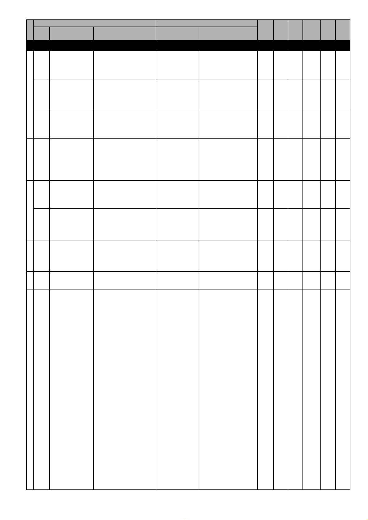
CODE NAME
C.000
Save parameters
PARAMETER PICK LIST
DESCRIPTION
[CODE]
FUNCTION
COMMAND
Save parameters command
off 0 (#)
No action.
DESCRIPTION
off
MIN
MAX
DEFAULT
do
UNIT
IPA
VARIATION
800
C.001
BasicAlarm ResetExternal KeyTuning
C.002
C.020
C.040
C.041
C.100
Recall param
Load default
Alarm clear
Recall key prog
Save pars to key
Measure statorR
Recall of the previous
stored parameters
Recall of the factory
parameters.
Completer reset of the the
Alarm List register
Recalling and storage of
the parameters in the
external key
Storage of the inverter
parameter on the external
key
Motor Autotune command
do 1 (#)
off 0 (#)
do 1 (#)
off 0 (#)
do 1 (#)
off 0 (#)
do 1 (#)
off 0 (#)
do 1 (#)
off 0 (#)
do 1 (#)
off 0 (#)
Save parameters
command.
No action.
Recall previously
parameters set.
No action.
Load default parameters.
No action.
Clear alarm register
command.
No action.
Recall parameter from
key.
No action.
Storage parameters to
key.
No action.
0 (#)
off
0 (#)
off
0 (#)
off
0 (#)
off
0 (#)
off
0 (#)
1 (#)
do
1 (#)
do
1 (#)
do
1 (#)
do
1 (#)
do
1 (#)
801
802
803
804
805
806
(#)
Serial command
do 1 (#)
Autotune command.
User Manual Chapter 7 - Parameters Description 55
Page 56
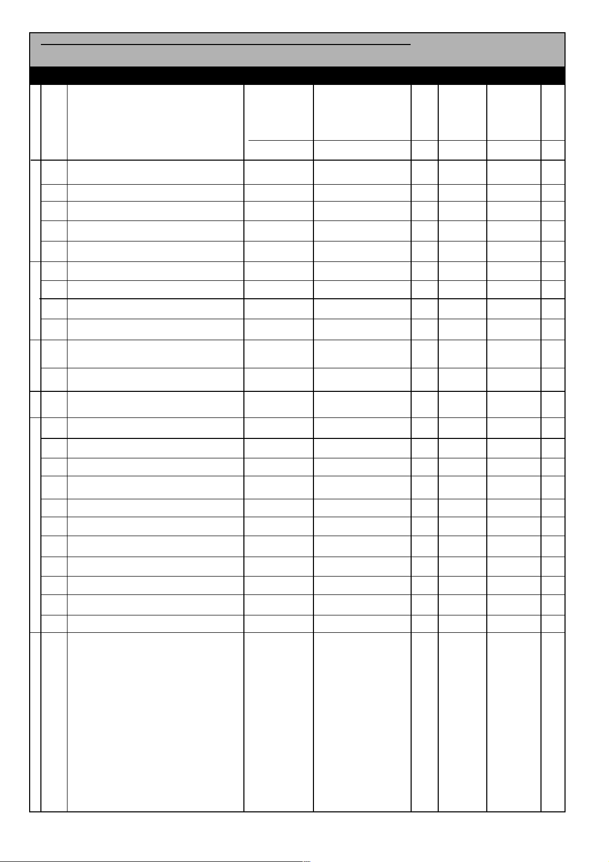
PARAMETER PICK LIST
CODE NAME
DESCRIPTION
This menu is not available on the
keypad. The setting and the reading of
the parameters here contained, can
be performed exclusively via serial line
or through SBI card.
H.000
Virtual digital command
H.010
Virtual digital state
H.040
Progress
H.050
Drive output frequency 16 bit low (d.000)
H.051
Drive output frequency 16 bit high (d.000)
Virtual I/Os CommandsProfidrive Profile
H.052
Drive reference frequency 16 low (d.001)
H.053
Drive reference frequency 16 high (d.001)
H.054
Output speed (d.000)*(P.600)16 bit low (d.007)
H.055
Output speed (d.000)*(P600)16 bit high(d.007)
[CODE]
FUNCTION
HIDDEN
DESCRIPTION
MIN
DEFAULT
0
0
0
0
0
0
0
0
0
- 2
- 2
- 2
- 2
- 2
- 2
0
0
0
31
31
31
31
31
31
MAX
UNIT
255
255
100
31
2
-1
65535
65535
65535
65535
32767
IPA
VARIATION
1000
1002
1009
1010
1011
1012
1013
1014
1015
H.056
H.057
Drive Status
H.064
H.500
H.501
H.502
H.503
H.504
H.505
H.506
H.507
Parameters Reading Extension
H.508
H.509
H.510
Speed Ref (d.001)*(P.600) 16 bit low (d.008)
Speed Ref (d.001)*(P.600)16 bit high(d.008)
Estimated real speed
Harware reset
Alarm reset
Coast to stop
Stop with ramp
Clockwise Start
Anti-clockwise Start
Clockwise Jog
Anti-clockwise Jog
Clockwise Flying restart
Anti-clockwise Flying restart
DC Brake
0
0
- 2
- 2
31
31
32767
32767
1016
1017
1046
0
0
0
0
0
0
0
0
0
0
0
0
0
0
0
0
0
0
0
0
0
0
1
1
1
1
1
1
1
1
1
1
1
1029
1030
1031
1032
1033
1034
1035
1036
1037
1038
1039
56 Chapter 7 - Parameters Description User Manual
Page 57

7.2 Menu d - DISPLAY
Basic
d.000 Output frequency
Drive output frequency [Hz].
d.001 Frequency ref (Frequency reference)
Drive frequency reference [Hz] .
d.002 Output current
Drive output current (rms) [A].
d.003 Output voltage
Drive output voltage (rms) [V].
d.004 DC link voltage
DC Bus drive voltage (DC) [V].
d.005 Power factor
Power factor.
d.006 Power [kW]
Active power.
d.007 Output speed
Drive output speed (d.000)*(P.600).
d.008 Speed ref (Speed reference)
Drive speed reference (d.001)*(P.600).
Code Name [Code] & Function Default MIN MAX Unit Variation IPA
d.000 Output frequency Hz 0,01 001
d.001 Frequency ref Hz 0,01 002
d.002 Output current A 0,1 003
d.003 Output voltage V 1 004
d.004 DC link voltage V 1 005
d.005 Power factor 0,01 006
d.006 Power [kW] kW 0,01 007
d.007 Output speed 0.01 / 1 008
d.008 Speed ref 0.01 / 1 009
Overload
d.050 Heatsink temp (Heatsink temperature)
Drive heatsink temperature [°C] (linear sensor measured).
d.051 Drive OL (Drive overload)
Drive overload (100% = alarm threshold).
User Manual Chapter 7 - Parameters Description 57
Page 58
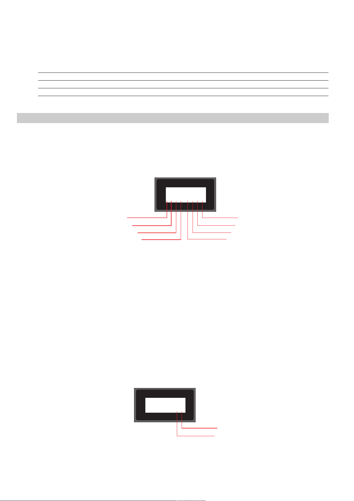
d.052 Motor OL (Motor overload)
Motor overload (100% = alarm threshold).
Code Name [Code] & Function Default MIN MAX Unit Variation IPA
d.050 Heatsink temp °C 1 010
d.051 Drive OL % 0.1 011
d.052 Motor OL % 0.1 012
Inputs/Outputs
d.100 Dig inp status (Digital inputs status)
Status of the digital inputs acquired by the drive. They can come from drive regulation board terminal inputs or
virtual inputs (ex.: by serial or field bus cards).
Example of displaying digital inputs with 7 segments display:
.I
Digital input8=OFF
Digital input7=OFF
Digital input6=OFF
Digital input5=ON
R
d.101 Term inp status (Teminal inputs status)
Status of the digital inputs terminal of the drive regulation board.
See example d.100
d.102 Vir dig inp stat (Virtual digital inputs status)
Status of the virtual digital inputs received by serial link or field bus card.
See example d.100
d.150 Dig out status (Digital outputs status)
Status of the digital outputs executed by the drive, on the drive regulation terminal outputs or virtual outputs (ex.:
by serial or field bus cards).
Example of displaying, of digital outputs with 7 segments display:
..I
.
Digital input1=ON
Digital input2=OFF
Digital input3=OFF
Digital input4=OFF
..I
.
R
58 Chapter 7 - Parameters Description User Manual
.
Digital output1=ON
Digital output2=OFF
Page 59

d.151 Term dig out sta (Terminal digital outputs status)
Status of the digital outputs terminal of the drive regulation board.
See example d.150
d.152 Vir dig out stat (Virtual digital outputs status)
Status of the virtual digital outputs executed by the drive serial link or field bus card.
See example d.150
d.200 An in 1 cnf mon (Analog input 1 configuration monitor)
It monitors the analog input 1 signal destination; it is possible to know which function is associated to this input:
[0] Null funct None function programmed
[1] Freq ref 1 Frequency reference 1 chapter FREQ & RAMPS, section Reference sources (F.050)
[2] Freq ref 2 Frequency reference 2 chapter FREQ & RAMPS, section Reference sources (F.051)
[3] Boost lev fac Level of voltage boost chapter PARAMETERS, section Boost (P.121)
[4] OT level fact Level of over torque chapter PARAMETERS, section OT level factor src (P.242)
[5] V red lev fac Output voltage reduction level chapter PARAMETERS, section Voltage Red Config P.422)
[6] DCB level fac DC braking current level chapter PARAMETERS, section DC brake Config (P.301)
[7] Ramp ext fact Ramp extension factor chapter PARAMETERS, section Ramp Config (F.260)
d.201 An in 1 monitor (Analog input 1 monitor)
Analog input 1 - output block (% value).
d.202 An in 1 term mon (Analog input 1 terminals monitor)
Analog input 1 input block % value (regulation board).
It monitors the input signal depending on the selection of An inp 1 Type (I.200) parameter:
selection: [1] 0-10V/0-20mA: 0V = 0%, +10V = +100% o 0mA=0% 20mA =
+100%
selection: [2] 4-20mA: 4mA = 0%, 20mA = +100%
Code Name [Code] & Function. Default MIN MAX Unit Variation IPA
d.100 Dig inp status 014
d.101 Term inp status 015
d.102 Vir dig inp stat 016
d.150 Dig out status 020
d.151 Term dig out sta 021
d.152 Vir dig out stat 022
d.200 An in 1 cnf mon 026
d.201 An in 1 monitor % 027
d.202 An in 1 term mon % 028
Pid
d.400 PID reference
PID reference signal.
d.401 PID feedback
PID feedback signal.
d.402 PID error
PID error signal.
User Manual Chapter 7 - Parameters Description 59
Page 60

d.403 PID integr comp (PID integral component)
PID integral component.
d.404 PID output
PID output signal.
Code LCD display [Code] & LCD select. Default MIN MAX Unit Variation IPA
d.400 PID reference % 0.1 041
d.401 PID feedback % 0.1 042
d.402 PID error % 0.1 043
d.403 PID integr comp % 0.1 044
d.404 PID output % 0.1 045
Alarm list
d.800 1st alarm-latest
Last alarm memory stored by the drive alarm list.
d.801 2nd alarm
Second to last alarm memory stored by the drive alarm list.
d.802 3rd alarm
Third to last alarm memory stored by the drive alarm list.
d.803 4th alarm
Fourth to last alarm memory stored by the drive alarm list.
Code LCD display [Code] & LCD select. Default MIN MAX Unit Variation IPA
d.800 1st alarm-latest 046
d.801 2nd alarm 047
d.802 3rd alarm 048
d.803 4th alarm 049
Drive Identification
d.950 Drive rated curr (Drive rated current)
Drive rated current (it is dependent on the drive size).
d.951 SW version (1/2) (Software version - part 1)
Display example: 03.00
03 = index of software identification
00 = index of software revision (new functions or parameters)
d.952 SW version (2/2) (Software version - part 2)
Display example: 00.00
00 = index of revision (fixing bugs)
00 = index of identification (special version)
NOTE!
to be considered as reference for SIEI personell
d.953 Power ident code (Power identification code)
Reserved.
60 Chapter 7 - Parameters Description User Manual
Page 61

d.954 Param ident code (Parameters identification code)
Reserved.
d.955 Regul ident code (Regulation identification code)
Reserved.
d.956 Startup id code (Startup identification code)
Reserved.
d.957 Drive size
Drive size code; Reserved.
Code Name [Code] & Function Default MIN MAX Unit Variation IPA
d.950 Drive rated curr 0,1 050
d.951 SW version (1/2) 0,01 051
d.952 SW version (2/2) 0,01 052
d.953 Power ident code 053
d.954 Param ident code 054
d.955 Regul ident code 055
d.956 Startup id code 056
d.957 Drive size 057
Utility
d.999 Display Test
Drive display test
Code Name [Code] & Function Default MIN MAX Unit Variation IPA
d.999 Display Test Drive display test 099
User Manual Chapter 7 - Parameters Description 61
Page 62
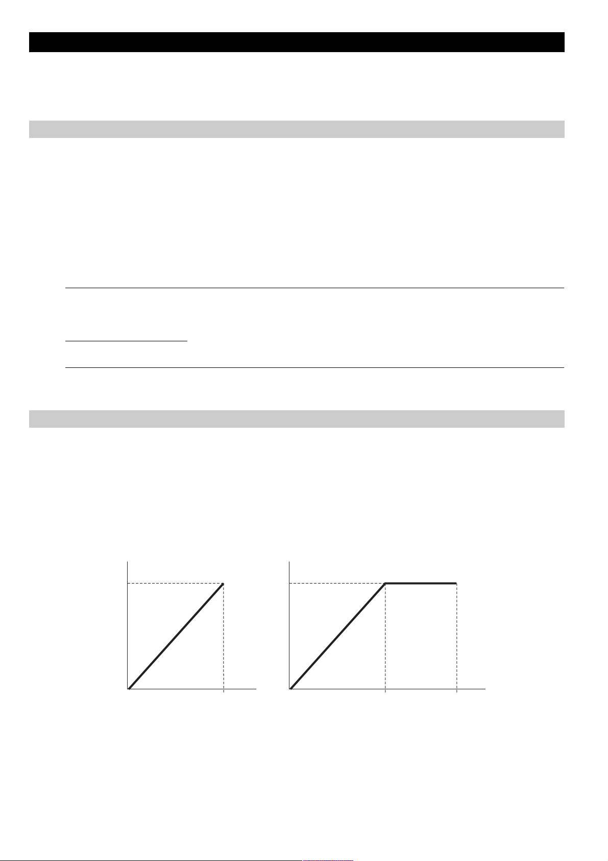
7.3 Menu S - START-UP
NOTE!
The START UP menu is a set of parameters and functions that allow a quick start of the motor.These
parameters are duplicated in other menus of the drive, Therefore, their modification can be performed
in any of the menus where the parametes are present.
Power Supply
S.000 Mains voltage
Rated value of the main voltage [V].
The undervoltage trip function is based on this value (see chapter PARAMETER, section Undervoltage
configuration).
S.001 Mains frequency
Rated value of the line voltage frequency [Hz].
Code Name [Code] & Function Default MIN MAX Unit Variation IPA
S.000 Mains voltage 110 230 110 240 V 404
S.001 Mains frequency 50 (****) 50 60 Hz 405
220
230
240
60
(****) parameter value dependent on drive type.
V/F Ratio
S.100 Max out voltage (Maximun output voltage)
Maximum value of the voltage applied to the motor (normally set as the nameplate, see figure 7.3.2).
S.101 Base frequency
Rated frequency of the motor (given on the nameplate, see figure 7.3.2)
It means the working frequency of the drive, at which the Max out voltage is associated (S.100).
V
S.100
V
S.100
(S.101)
(S.201)
NOTE!
62 Chapter 7 - Parameters Description User Manual
For further setting of the V/F ratio, see the chapter PARAMETER, section V/F Curve
F
(n)
Figure 7.3.1: V/F Ratio
S.101
S.201
F
(n)
Page 63
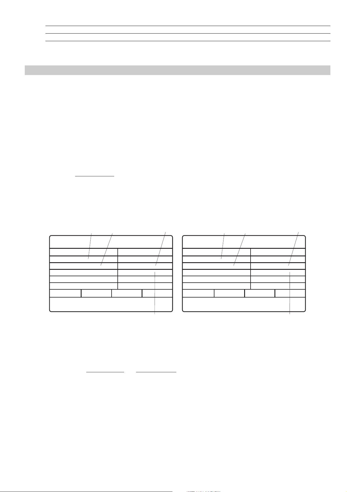
Code Name [Code] & Function Default MIN MAX Unit Variation IPA
S.100 Max out voltage (**) 50 (**) V 1 413
S.101 Base frequency (**) 25 500 Hz 0,1 414
(**) parameter value dependent on drive nominal main voltage and main frequency.
Motor Data
S.150 Motor rated curr (Motor rated current)
Rated current of the motor at rated kilowatt/horsepower and voltage (given on the nameplate, see figure7.3.2).
In case of control with multiple motors, enter a value equal to the sum of the rated currents of all the motors.
Do not perform any self tune.
S.151 Motor pole pairs
Pole pairs of the motor.
The setting of this data, can be easily calculated with the following formula:
N[rpm] =
60 [s] x f [Hz]
2p [polepairs]
where: p = motor pole pairs
f = rated frequency of the motor (S.101)
nN = rated speed of the motor (see figure 7.3.2).
S.101 (P.062)
S.100 (P.061)
Motor & Co.
Type: ABCDE
Motor: 3 phase
Rated voltage
Rated power
Rated speed (n )
IP54
Made in ..............
Figure 7.3.2: Motor Nameplate (Example: kW rating for 400V motor and Hp rating for 575V motor)
50 Hz
400 V
3kW
1420 rpm
N
Iso Kl F
Nr
I nom
Power factor
S1
S.150 (P.040)
IEC 34-1 / VDE 0530
.
12345-91
6.7 A
0.8
S.152 (P.042)
S.101 (P.062)
Motor & Co.
Type: ABCDE
Motor: 3 phase
Rated voltage
Rated power
Rated speed (n )
IP54
Made in ..............
N
60 Hz
575 V
2Hp
1750 rpm
Iso Kl F
S.100 (P.061)
S1
IEC 34-1 / VDE 0530
Nr
.
I nom
Power factor
Efficiency
12345-91
2A
0.83
86.5
S.152 (P.042)
S.150 (P.040)
Example: calculation of the pole pairs of a motor having the data shown in the above 575V label:
p [polepairs] =
60 [s] x f [Hz]
n [rpm]
N
60 [s] x 60 [Hz]
==2
1750 [rpm]
the value to set in the parameter S.152 is "2"
S.152 Motor power factor
Motor power factor (given on the nameplate, see figure7.3.2).
User Manual Chapter 7 - Parameters Description 63
Page 64

S.153 Motor stator R (Motor stator Resistance)
Measurements of the stator resistance of the motor.
This value will be automatically updated, by performing the self tune procedure.
Code Name [Code] & Function Default MIN MAX Unit Variation IPA
S.150 Motor rated curr (*) (*) (*) A 0.1 406
S.151 Motor pole pairs (*) 1 60 407
S.152 Motor power fact (*) 0.01 1 0.01 408
S.153 Motor stator R (*) 0 99.99 ohm 0.01 409
(*) parameter value dependent on drive size.
Commands & Referencies
S.200 Cmd source sel (Command source selection)
It defines the use of the main commands START and STOP .
S.200 = 1 START & STOP via terminals
In this configuration the commands are active through the drive terminals.
The motor START command can be performed by applying the specific logic level (high level +15V) ,
to the Digital Input 1 (terminal 5), factory set as RUN If this connection is removed, the motor
will STOP with the set ramp time.
For this connection refer to figure 5.3.2.1.
NOTE!
NOTE!
Main Commands Logic Control:
START & STOP
After a cycle of main supply voltage, the drive can be started only according to the settings of
P.003 Safety parameter, which allows the Start/Stop commands to respond to Edge or Level sensitive
signals (see chapter 7.6 for more details).
Other configurations for the setting of the "main commands" are described in the chapter
PARAMETERS, section Commands.
The START & STOP function configuration is correlated to other functions and parameters as well as the
mode to REVERSE the motor speed.
These functions allow additional control logic and safety control.
For further information, see chapter PARAMETER, section Commands .
MOTOR SPEED REVERSAL
There are several way to REVERSE the speed direction of the motor.
As a default factory setting, the Digital Input 2 (terminal 7) is programmed to this purpose.
All of the frequency references or other variables controlled with digital setting or analog signal, can be
programmed either with positive or negative values. The polarity of the value (Digital or Analog) will determine the
motor rotation direction, without the use of any external HW commands.
Despite the polarity of the reference, the REVERSE command, if programmed on a digital input, will always
reverse the speed direction of the motor.
S.201 Max ref freq (Maximun reference frequency)
It is the threshold for the analog or digital reference and the maximum speed for both directions.
This parameter applies to the sum of the two references value available on the drive.
64 Chapter 7 - Parameters Description User Manual
Page 65

S.202 Ref 1 Channel (Reference 1 channel)
It defines the source from where the Reference 1 is provided and controlled.
For further details please refer to chapter FREQ & RAMPS, section Reference Source.
S.203 Frequency ref 0 (Frequency reference 0)
Digital speed reference.
It is also the first digital frequency of the Multispeed selection (F.100F.116).
It is possible to set setting with positive or negative values.
The polarity will determine the sense of rotation of the motor.
In either polarity the setting the HW Reverse command is active (when enabled).
The maximum settable value is correlated to Max ref freq (S.201).
Code Name [Code] & Function Default MIN MAX Unit Variation IPA
S.200 Cmd source sel [1] Terminals 1 0 4 400
[2] Virtual
[3] FoxLink
[4] Control word
S.201 Max ref freq (****) 25 500 Hz 0.1 305
S.202 Ref 1 channel [0] Null 3 0 8 307
[1] Analog inp 1 (setting through I.200I.204)
[2] not used
[3] Freq ref x (setting through S.203 or F.100)
[4] Multispeed (setting through F.100F.116)
[5] Motorpotent (setting through F.000F013)
[6] not used
[7] not used
[8] not used
S.203 Frequency ref 0 0 -S.201 S.201 311
(****) parameter value dependent on drive type.
S.300 Acc time 1 (Acceleration time 1)
S.301 Dec time 1 (Deceleration time 1)
The ramp control can be set to allow a programmable delay (in seconds), for the acceleration and deceleration
times of the drive reference.
This delay time will have to be set on the final system (motor and load), being strictly dependant from the inertia
of the load machine.
The ramps time delay, are calculated in accordance with the Max ref freq (S.201).
The setting can be carried out as follows, according to the setting of the parameter F. 20 0.
Code Name [Code] & Function Default MIN MAX Unit Variation IPA
S.300 Acc time 1 5 1 999.9 sec 0.1 (***) 329
S.301 Dec time 1 5 1 999.9 sec 0.1 (***) 330
Functions
S.400 Manual boost [%]
The resistive impedance of the stator windings causes a voltage drop within the motor, which result in a reduction
in torque in the lower speed range.
Compensation can be made for this effect by boosting the output voltage.
This compensation is carried out continuously across the whole speed range in proportion to the output current
but it is most effective at low speed.
User Manual Chapter 7 - Parameters Description 65
Page 66
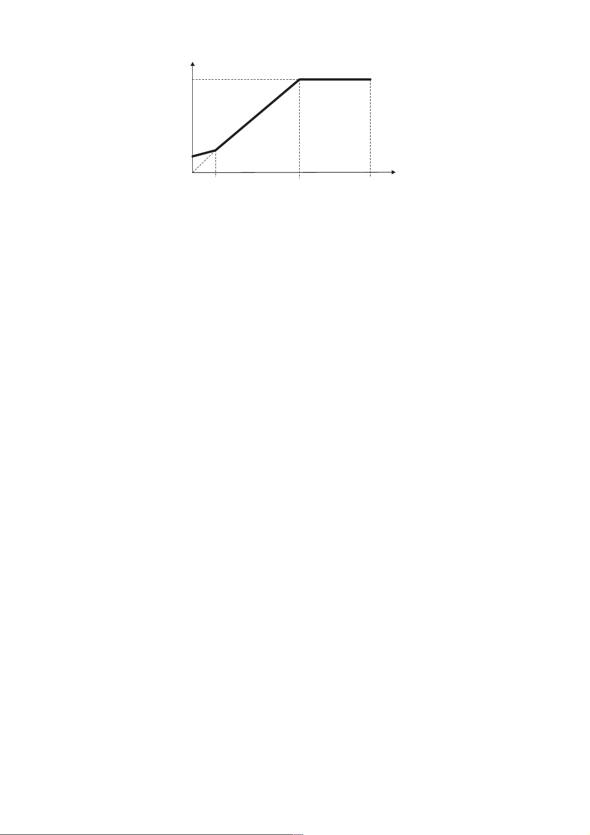
S.100
S.400
V
P.064
Figure 7.3.3: Manual Boost Voltage
The setting is in percentage of the Max out voltage (S.100).
NOTE!
When custom V/f shape is selected (P.060 = 0):
P. 0 6 4 parameter represents the return point of the output voltage, on the linear characteristic of V/f
ratio (see figure 7.3.3).
S.401 Auto boost en (Automatic boost enabling)
The boost can be automatically controlled by the enabling of this parameter. The control is continuously carried
out in the whole speed range.
The Auto boost must be disabled when a multiple motor connection is being used.
NOTE!
The automatic boost is automatically calculated during the execution of drive/motor self tuning (S.901
parameter).
It is anyway possible to obtain an "Oveboost" at low speed, increasing the value of the manual boost
(S.400 parameter).
S.101
S.201
F
(n)
S.450 Slip compensat (Slip compensation)
If an induction motor is being used, the mechanical speed will vary with the load due to the slip of the motor.
In order to adjust for this speed error the slip compensation can be used.
During this calibration, make sure that the drive is not in a current limit condition.
If this compensation is set too high it can cause instability.
The changing will be carried out as a percentage of the nominal slip, calculated when set the motor plate date.
The Slip compensation will act directly on the output frequency of the drive. To this purpose the parameter
Max output freq (P.080) expressing the percentage of the Max ref freq (F.020), has to be set to a value
including:
Max ref freq value + Slip compensat value.
(See also chapter PARAMETER, section Output Frequency Limit).
The Slip compensation must be disabled when a multiple motor connection is being used.
S.451 Slip comp filter (Slip compensation filter)
It is the response time (in seconds) for the reaction of the function.
Increasing this value helps damping oscillations that may arise with load steps (especially negative ones).
66 Chapter 7 - Parameters Description User Manual
Page 67
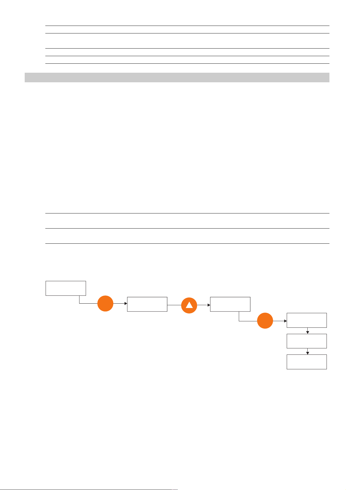
Code Name [Code] & Function Default MIN MAX Unit Variation IPA
S.400 Manual boost [%] 1 0 25 % of S.100 421
S.401 Auto boost en [0] Disable 0 0 1 423
[1] Enable
S.450 Slip compensat 0.1 0 10 % 419
S.451 Slip comp filter 0.1 0 10 sec 0.1 420
Utility
S.900 Measure stator R (Measurement of stator resistance)
It measures the stator resistance of the motor connected.
This will help to provide a smooth and uniform value of the output torque through the whole speed range.
The control is assisted by the use of the Automatic boost (P.401).
Do not perform any tune when a multiple motor connection is being used.
S.901 Save parameters
Every changing of each parameter, is accepted and executed by the drive.
However, the permanent storage of them, is performed only by the execution of this command.
The lack of this operation will cause the loss of every changed parameter when the power is disconnected from
the drive.
Code Name [Code] & Function Default MIN MAX Unit Variation IPA
S.900 Measure stator R Confirm ? off off off do 806
Confirm ? do
S.901 Save parameters Confirm ? off off off do 800
Confirm ? do
Here below is an example of how to execute the Save parameters command. It is also valid for Measure
stator R (S.900) command.
STARTUP S901
Save parameters
E
Save parameters
Confirm? NO
Save parameters
Confirm? YES
E
Save parameters
Run
Save parameters
Done
STARTUP S901
Save parameters
User Manual Chapter 7 - Parameters Description 67
Page 68

7.4 Menu I - INTERFACE
Digital Inputs Regulation Board
I.000 Dig input 1 cfg (Digital input 1 configuration)
I.001 Dig input 2 cfg (Digital input 2 configuration)
I.002 Dig input 3 cfg (Digital input 3 configuration)
I.003 Dig input 4 cfg (Digital input 4 configuration)
I.004 Dig input 5 cfg (Digital input 5 configuration) Not used
The regulation board provides as standard 8 opto-coupled digital inputs. A PNP or NPN logic level, can be selected according
to figure 5.5.1. Every input is programmable with a specific code and function, as shown in the list below.
DIGITAL INPUTS SELECTION LIST:
Code LCD display Description
0 None Not active
1Run RUN command for the motor START
2 Reverse Speed REVERSE command
3 Ext Fault NO External fault with NO (Normal Open) contact
4 Ext Fault NC External fault with NC (Norm. Closed) contact
5 Alarm reset Alarm reset command
6Jog JOG frequency reference enabling
7 Freq sel 1 Binary selection for Multispeed
8 Freq sel 2 Binary selection for Multispeed
9 Freq sel 3 Binary selection for Multispeed
10 Freq sel 4 Binary selection for Multispeed
11 Ramp sel 1 Binary selection for Multiramp
12 Ramp sel 2 Binary selection for Multiramp
13 Enable NO Drive Enable with NC (Norm. Closed) contact
14 Enable NC Drive Enable with NO (Normal Open) contact
15 DCBrake en Enabling of the DC braking function
16 DCBrake Command for execution of DC braking
17 Autocapture Execution of the flying restart
18 Ramp enable Enabling / Disabling of the Ramp block
19 Zero ref Ramp to 0Hz & main commands active
20 PID enable Enabling of the PID regulation
21 PID freeze Enabling PID freeze output signal.
22 PID gain sel Initilizing of the Integral value of PID
23 Motorpot Up Motorpotentiometer reference increasing
24 Motorpot Dn Motorpotentiometer reference decreasing
25 Reset Motorp Reset of Motorpotentiometer reference
26 Fast stop Emergency stop (with Dec time 3 delay)
27 Zero freq Enabling output freq. to zero.
Code Name [Code] & Function Default MIN MAX Unit Variation IPA
I.000 Dig input 1 cfg See Digital inputs selection list 7 0 27 100
I.001 Dig input 2 cfg As for I.000 8 0 27 101
I.002 Dig input 3 cfg As for I.000 9 0 27 102
I.003 Dig input 4 cfg As for I.000 6 0 27 103
68 Chapter 7 - Parameters Description User Manual
Page 69

The digital inputs are FACTORY set as follow:
Dig input 1 cfg (Terminal 4) = 1 Run
Dig input 2 cfg (Terminal 5) = 3 External fault
Dig input 3 cfg (Terminal 6) = 2 Reverse
Dig input 4 cfg (Terminal 7) = 7 Freq. sel. 1
Dig input 5 cfg ( Not available) = 0 Null
Digital Ouputs Regulation Board
I.100 Dig output 1 cfg (Digital output 1 configuration) RELE'
I.101 Di g output 2 cfg (Digital ou tput 2 configura t i on) Not avai l a ble
The regulation board provides one relay with commutation contacts (see figure 5.5.1).
Every output is programmable with a specific code and function, as shown in the list below.
DIGITAL OUTPUTS SELECTION LIST:
Code LCD display Description
0 Drive Ready Drive ready to start
1 Alarm state Positive logic for alarm signalling
2 Not in alarm Negative logic for alarm signalling
3 Motor running Direction command active
4 Motor stopped Direction command not active and frequency = 0Hz
5 REV rotation Anti-clockwise rotation of the motor
6 Steady state Motor is running in steady state
7 Ramping Acceleration or Deceleration Ramp in progress
8 UV running Undervoltage detection during motor running
9 Out trq>thr Output torque higher than the value of P.241
10 Current lim Current limit (during ramp or at steady state)
11 DC-link lim DC Bus limit (during ramp or at steady state)
12 Limit active General signalling of drive limit condition
13 Autocapt run Autocapture on progress
14 BU overload Overload of the braking resistor
15 Neg pwrfact Negative condition of the power factor
16 PID err >< PID error is >A.058 & <=A.059
17 PID err>thr PID error is >A.058
18 PID err<thr PID error is <=A.059
19 PIDer><(inh) PID error is >A.058 & <=A.059 (*)
20 PIDerr>(inh) PID error is >A.058 (*)
21 PIDerr<(inh) PID error is <=A.059 (*)
22 Not used
23 Not used
24 Not used
25 Not used
26 Extern fault Positive logic for Ext. fault alarm signalling
27 No ext fault Negative logic for Ext. fault alarm signalling
28 Serial TO Serial link communication time out
29 freq=thr1 Output frequency = to P.440 & P.441 values
30 freq!=thr1 Output frequency
31 freq>thr1 Output frequency > than P.440 & P.441 values
32 freq<thr1 Output frequency < than P.440 & P.441 values
33 freq=thr2 Output frequency = to P.442 & P.443 values
34 freq!=thr2 Output frequency
35 freq>thr2 Output frequency > than P.442 & P.443 values
≠≠
≠ of P.440 & P.441 values
≠≠
≠≠
≠ of P.442 & P.443 values
≠≠
User Manual Chapter 7 - Parameters Description 69
Page 70
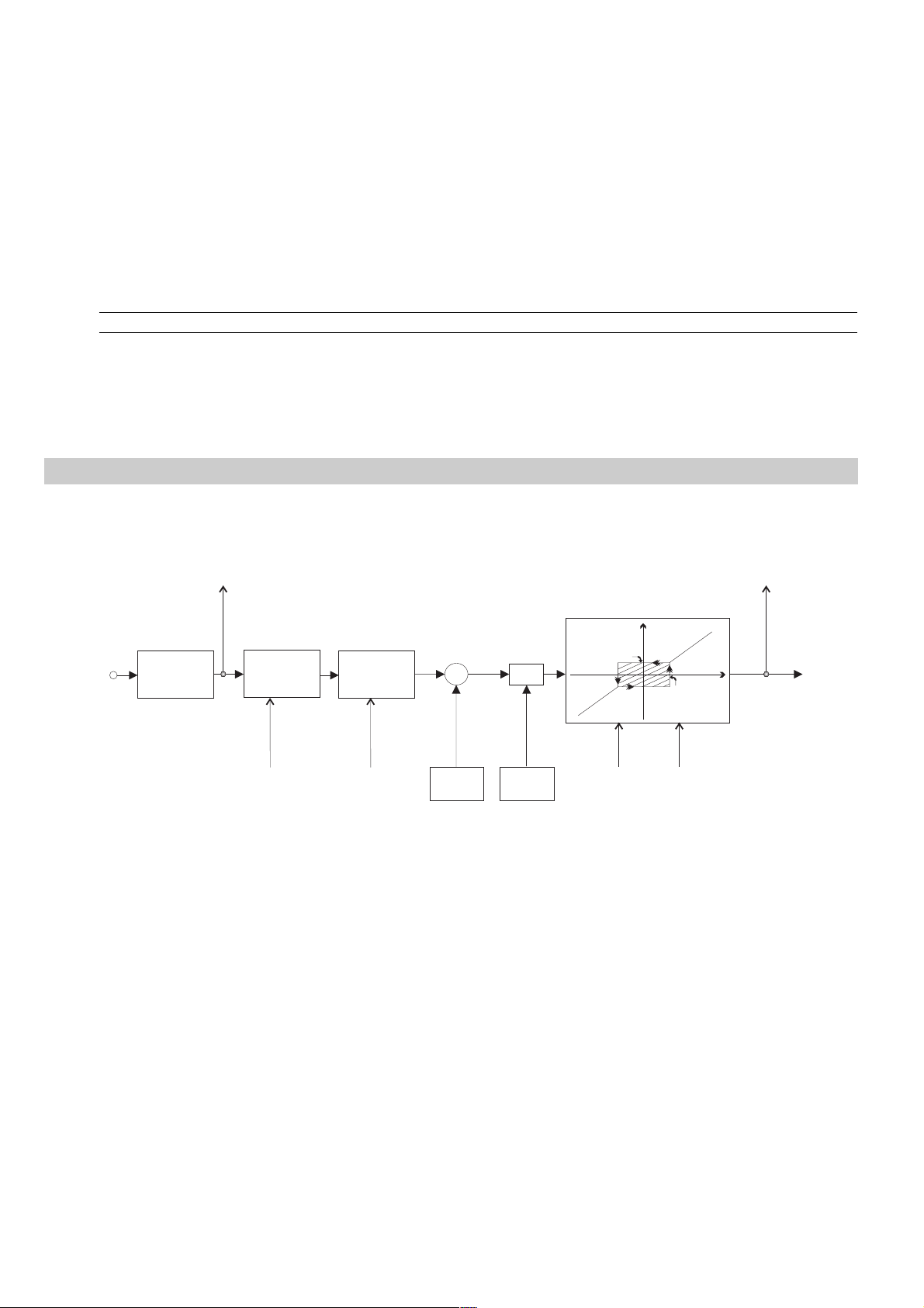
36 freq<thr2 Output frequency < than P.442 & P.443 values
37 HS temp=t h r Heatsink temp = to P. 4 8 0 & P. 4 8 1 values
38 HS temp!=thr Heatsink temp
39 HS temp>t h r Heatsink temp > than P. 48 0 & P. 4 8 1 values
40 HS temp<t h r Heatsink temp < than P. 48 0 & P. 4 8 1 values
41 Output freq Frequency in synchronism with output frequency
42 Out freq x 2 Frequency value x 2 in synchronism with output frequency
43 OutCoastThru Coast Through stopping
44 OutEmgStop Emergency stop
(*) see chapter 7.7, section PID Limit.
Code Name [Code] & Function. Default MIN MAX Unit Variation IP
I.100 Dig output 1 cfg See Digital Outputs selection list 0 0 44 112
The digital outputs are FACTORY set as follow:
Dig output 1 cfg - relay type (Terminal 1 - 2 - 3) = 0 Drive Ready
Analog Inputs Regulation Board
≠≠
≠ of P. 4 8 0 & P. 4 8 1 values
≠≠
The drawing below, describes the block diagram of the standard "Analog Inputs" of the drive.
Monitor
d 202
Terminal
AN-INPUT
10 bits+sign
converer
Filtro
T Delay
I 204
Selection
Ref. Type
I 200
+
+
Offset
I 201
X
Gain
I 202
I 203
min
I 203
OUT
Clipping
I 205
Figure 7.4.1: Analog Inputs
The regulation board provides as standard analog inputs.
Analog inputs resolution:
voltage input setting: 11 bits (10 bits + sign)
current input setting: 10 bits
I 205
Monitor
d 201
IN
To Drive
A typical basis connection is reported in the figure 5.5.1.1.
The assignment of the Analog Inputs for a specific function, is described in the figure 7.5.1 at the menu FREQ
and RAMPS.
I.200 An In 1 type (Analog Input 1 type)
Setting of the Analog Input 1, in accordance with the type of reference control, available on its HW.
I.200 = 1 Unipolar +10V o 0-20mA
I.200 = 2 4-20mA
70 Chapter 7 - Parameters Description User Manual
Page 71
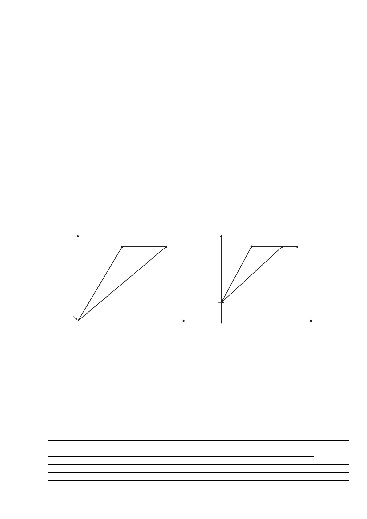
I.201 An In 1 offset (Analog Input 1 offset)
I.202 An In 1 gain (Analog Input 1 gain)
Gain of the analog input.
It can be used to amplify or reduce the ratio between signal and controlled variable, or also to set different types
of control curves via analog reference, as described in the figures 7.4.2, 7.4.3 and 7.4.4.
Each parameters acts on the relative analog input.
I.203 An In 1 minimum (Analog Input 1 minimun)
It represents the minimum value of the parameter, on which the analog input is programmed (see figure 7.4.3).
Example: if the analog input 1 is programmed as speed reference, in this case I.203 represents the minimum
speed reference.
Each parameters acts on the relative analog input.
I.204 An In 1 filter (Analog Input 1 filter)
It is the response time of the signal reaction to the reference variations.
Each parameters acts on the relative analog input.
The use of the Analog Inputs parameters set, can be useful to customize the analog reference ratio.
In the figures below are reported some samples.
AnInp Drive
100%
I.201
I.202=2
5V
I.202=1
10V
AnInp Drive
100%
I.201
I.202=2
Figure 7.4.2: Analog Input Scaling 1
An Inp Drive [%] = I.202 x An Inp [%] + x 100()
NOTE!
When the analog input reference is set at 0V, an eventual "noise" can cause undesired speed oscillation
I.201
10
between positive and/or negative values of I.203 parameter.
I.202=1
10V
Code Name [Code] & Function. Default MIN MAX Unit Variation IPA
I.200 An in 1 Type [1] 0-10V / 0-20mA 1 0 1 118
[2] 4-20mA
I.201 An in 1 offset 0 -99.9 99.9 % 0.1 119
I.202 An in 1 gain 1 -9.99 9.99 % 0.01 120
I.203 An in 1 minimum 0 0 99.99 % 0.01 121
I.204 An in 1 filter 0.1 0.001 0.25 sec 0.001 122
User Manual Chapter 7 - Parameters Description 71
Page 72
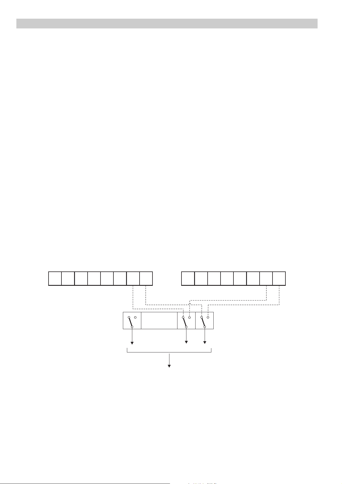
Enabling Virtual I/O
Through a virtual setting via serial line or fieldbus, it is possible to use all the functions available on the digital inputs and
perform a direct control of the digital and analog outputs.
The setting can be carried out in such configurations, where the digital commands are a mix of virtual and terminals and
the outputs are a mix of virtual and drive function.
The virtual assignment can be performed through the parameters H.000H.022 in the HIDDEN menu (for further
information please see this chapter).
Below are the reported the drawings describing the combination between the byte of the virtual I/Os and the drive
terminals, with the relative decoder mask.
The switch between the virtual commands and the terminal ones and between the virtual output or the drive
functions, is determined by programmable mask I.400I.450.
These parameters have to be managed bitwise. At each bit corresponds a switch, as follows.
Bit value Inputs Outputs
0 Terminal Drive function
1 Virtual Virtual control
The formula below describes the result of the virtual I/Os setting:
[Input/Output AND (NOT Mask)] OR (Virtual AND Mask)
VIRTUAL DIGITAL INPUTS CONFIGURATION
Terminal digital inputs
d.101
DI
8
DI
DI
6
7
DI
DI
4
5
DI
DI
DI
2
3
0
1
1
Mask
Bit 7...............................Bit 1 Bit 0
To internal drive
Mask bits = 0 DIxx activeÞ
Mask bits = 1 VIxx activeÞ
digital commands
I.000 … I.007
Virtual digital inputs
VI
8
0
1
VI
VI
6
7
0
1
VI
VI
4
5
VI
VI
2
3
VI
1
H.000
d.102
I.400
Figure 7.4.5: Virtual digital inputs configuration
72 Chapter 7 - Parameters Description User Manual
Page 73
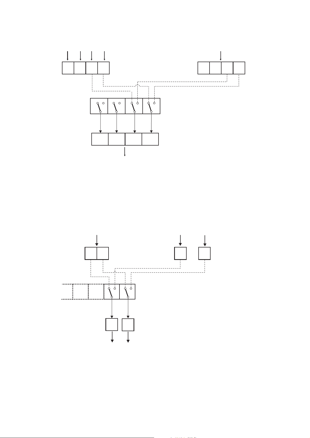
VIRTUAL DIGITAL OUTPUTS CONFIGURATION
Drive logical states
I.103 ........... I.100
Virtual settings
d.150
IDO
4
IDO
3
IDO
2
IDO
1
0
0
1
0
1
Mask
Bit 3
Bit 2
DO
DO
4
DO
3
Terminal drive outputs
Figure 7.4.6: Virtual digital outputs configuration
VIRTUAL ANALOG OUTPUTS CONFIGURATION
2
1
Bit 1
0
DO
1
1
Bit 0
I.400
Mask bits = 0 DOxx setting activeÞ
Mask bits = 1 VOxx setting activeÞ
VO
4
VO
3
VO
2
VO
1
H.010
d.152
Internal drive variables
IAO2IAO
I.310
I.300
1
0
1
Bit 1
AO
2
Terminal drive outputs
Figure 7.4.7: Virtual analog outputs configuration
Virtual variables
VAO
H.021
0
1
2
VAO
1
H.020
Mask I.450
Bit 0
AO
1
Mask bits = 0 AOxx value activeÞ
Mask bits = 1 VAOxx value activeÞ
User Manual Chapter 7 - Parameters Description 73
Page 74

Below are some examples about the programming of the basic function via virtual assignment.
A) DIGITAL INPUTS
Programming example for:
RUN and REVERSE commands via virtual mode
EXT FAULT command via terminal
P.000 = 2 Function mode enabled
I.400 = 3 bit 0 and bit 1 are high (1) and bit 5 is low (0)
I.000 = 1 RUN (programmed on digital input 1)
I.001 = 2 REVERSE (programmed on digital input 2)
I.005 = 3 EXTERNAL FAULT (programmed on digital input 6)
Writing H.000 = 1 the motor will turn in FORWARD direction
Writing H.000 = 3 the motor will turn in REVERSE direction
Writing H.000 = 0 the motor will STOP
Refer to chapter 7.9 for more informations on H.000 parameter.
The EXTERNAL FAULT command will be applied removing the potential at the terminal 6 (programmed as digital
input 6).
B) DIGITAL OUTPUTS
Programming example for:
ALARM STATE signalling on Digital output 1
VIRTUAL FUNCTION signalling on Digital outputs
P.000 = 2 Function mode enabled
I.420 = 2 bit 1 is high (1) and bit 0 is low (0)
I.100 = 1 ALARM STATE (programmed on digital output 1)
I.101 = 2 ANY SELECTION (programmed on digital output 2)
Digital output 1 active in accordance with the drive alarm status
Digital output 2 active if bit 1 of H.010 = 1
not active if bit 1 of H.010 = 0
C) ANALOG OUTPUTS
Programming example for:
OUTPUT FREQUENCY signalling on Analog output 1
VIRTUAL SETTING on Analog output 2
P.000 = 2 Function mode enabled
I.450 = 2 bit 1 is high (1) and bit 0 is low (0)
I.300 = 0 OUTPUT FREQUENCY (programmed on analog output 1)
74 Chapter 7 - Parameters Description User Manual
Page 75

I.310 = 2 ANY SELECTION (programmed on analog output 2)
Analog output 1 signal proportional to the OUTPUT FREQUENCY of the drive
Analog output 2 signal proportional to the setting of H.021
H.021: + 32767 output = +10V
H.021: - 32767 output = - 10V
I.400 Inp by serial en
It defines the bits of the mask, that are active for the virtual assignment. A byte is available for the selection of 8
digital inputs, whose setting has to be carried out as decimal value.
Bit 0 = 1 Enabled
Bit 1 = 2 Enabled
Bit 2 = 4 Enabled
Bit 3 = 8 Enabled
Bit 4 = 16 Enabled
Bit 5 = 32 Enabled
Bit 6 = 64 Enabled
Bit 7 = 128 Enabled
I.410 Exp in by ser en (Expansion inputs by serial line enabling)
Reserved.
I.420 Out by serial en (Outputs by serial line enabling)
It defines the bits of the mask, that are active for the virtual assignment. A 4 bits structure is available for the
selection of 4 digital outputs, whose setting has to be carried out as decimal value.
Bit 0 = 1 Enabled
Bit 1 = 2 Enabled
Bit 2 = 4 Enabled
Bit 3 = 8 Enabled
Code Name [Code] & Function. Default MIN MAX Unit Variation IPA
I.400 Inp by serial en 0 0 255 145
I.410 Exp in by ser en 0 0 15 146
I.420 Out by serial en 0 0 15 147
I.430 Exp OutBySer en 0 0 3 148
I.450 An out by ser en 0 0 255 149
Enabling of the encoder feedback management.
Serial Configuration
The DVS provides as a standard an RS485 serial line.
For the connection of the serial line, a 9-pin SUB-D connector, named JP7 or an AMP connector named JP15 (see
chapter 5.4.1 Serial Interface General). are available on the regulation card.
Through the serial line, all the parameters and variables can be written and read.
When control of the main command through serial line is needed, it is necessary to set the Cmd source sel (P.000) as
follows:
P.000 = 2 Terminal or Virtual
P.000 = 3 Serial
Further information are reported at the chapter PARAMETER, section Commands .
User Manual Chapter 7 - Parameters Description 75
Page 76

I.600 Serial link cfg (Serial link configuration)
Selection of the serial line protocol.
Each protocol can be chosen through the setting of the following codes. The structure of them is below reported.
DEFAULT VALUE = 4 (Modbus protocol)
I.601 Serial link bps (Serial link bit per second)
It defines the Baud rate (bit per second) concerning the serial line communication speed.
The selection is through the following code:
I.602 Device address
Address at which the drive can be accessed if it is networked via the RS485 interface.
The range of the selectable addresses is between 0 and 99.
As reported in the chapter 5.4.1 (Serial Line General), it is possible to perform a Multidrop configuration with a
maximum of 20 devices.
Further information about are reported in this chapter.
I.603 Ser answer delay (Serial link answer delay)
Minimum delay setting between the reception of the last byte and the start of its answer.
The delay will help avoid conflicts on the serial line, when the RS485 interface is not preset for an automatic Tx/
Rx communication.
The Ser answer delay (I.603) parameter is specific for the standard serial line RS485.
Eg: if on the master the Tx/Rx delay communication is 20ms max, the setting of Ser answer delay (I.603)
parameter will have to be higher than 20ms: 22ms.
I.604 Serial timeout (Serial link timeout)
It sets the time that elapses between the sending/receiving of a byte and the next one.
If this time is longer than the setting and no byte is detected (sending/receiving), the action will be the one
programmed in the parameter I.605
The alarm won't be active when set at 0 second.
It will be displayed with the message "St".
NOTE!
Even if the timeout control function is enabled at the drive power-on, the detection of "St" alarm is
temporary non active.
The detection of the alarm will be automatically activated after the first restore of the communication
between master and slave.
I.605 En timeout alm (Enabling serial link timeout alarm)
Setting of the behaviour for Serial time out alarm.
I.605 = 0 Signalling of the alarm on a digital output (programmed to this purpose)
I.605 = 1 Drive in alarm and signalling on a digital output (programmed to this purpose)
Code Name [Code] & Function. Default MIN MAX Unit Variation IPA
I.600 Serial link cfg [0] FoxLink 7E1 4 0 5 155
[1] FoxLink 701
[2] FoxLink 7N2
[3] FoxLink 8N1
[4] ModBus 8N1
[5] JBus 8N1
76 Chapter 7 - Parameters Description User Manual
Page 77

I.601 Serial link bps [0] 600 baud 4 0 9 156
[1] 1200 baud
[2] 2400 baud
[3] 4800 baud
[4] 9600 baud
[5] 19200 baud
[6] 38400 baud
[7] 57600 baud
[8] 76800 baud
[9] 115200 baud
I.602 Device address 1 0 99 1 157
I.603 Ser answer delay 1 0 250 msec 1 158
I.604 Serial timeout 0 0 25 sec 0,1 159
I.605 En timeout alm [0] Disable 160
[1] Enable
User Manual Chapter 7 - Parameters Description 77
Page 78
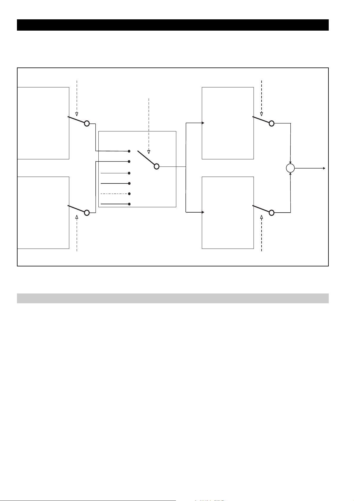
7.5 Menu F - FREQ & RAMPS
The drawing below, describes the logic for the "Reference selection".
Channel 1
Null 0
AN INP 1 1
F.100
MOTORPOT 5
NULL 6
FIELDBUS 8
Channel 2
Null 0
AN INP 1 1
F.101
MOTORPOT 5
NULL 6
FIELDBUS 8
Multi Freq. 1 Channel
F.060
o
o
2
o
3
o
4
o
Digital Input HW
Multi Freq. Sel
o
o
7
o
o
o
o
2
o
3
o
4
o
Multi Freq. 1
Multi Freq. 2
F.102
F.103
F.107
0
1
2
3
o
o
7
o
Multi Freq. 2 Channel
o
F.061
Ref 1
Null 0
AN INP 1 1
F.100
MULTI SPEED 4
MOTORPOT 5
NULL 6
FIELDBUS 8
Ref 2
Null 0
AN INP 1 1
F.101
MULTI SPEED 4
MOTORPOT 5
NULL 6
FIELDBUS 8
2
3
7
2
3
7
Ref. 1 Channel
F.050
o
o
o
o
o
o
o
o
o
o
o
o
o
o
o
o
o
Ref. 2 Channel
o
F.051
+
Reference
+
Figure 7.5.1: Reference Selection
Motorpotentiometer
F.000 Motorpot ref (Motorpotentiometer reference)
When this parameter is shown, the UP and DOWN keys are activated to increase or decrease the frequency
value.
Pressing the UP and DOWN Keys will cause the motor to increase or decrease its speed respectively until the
keys are released.
The maximum value settable is correlated to Max ref freq (F.020).
To START the motor it is necessary a RUN command.
The Motorpotentiometer reference can also be changed via digital inputs, programmed as
Motorpot up and Motorpot down.
The reset of the reference value, can be executed via digital input programmed as Reset Motorpot.
F.010 Mp Acc / Dec time (Motorpotentiometer Acceleration / Deceleration time)
It sets the acceleration and deceleration ramp time delay (in seconds), for the Motorpotentiometer function.
The delay times are equal for the acceleration and deceleration.
78 Chapter 7 - Parameters Description User Manual
Page 79
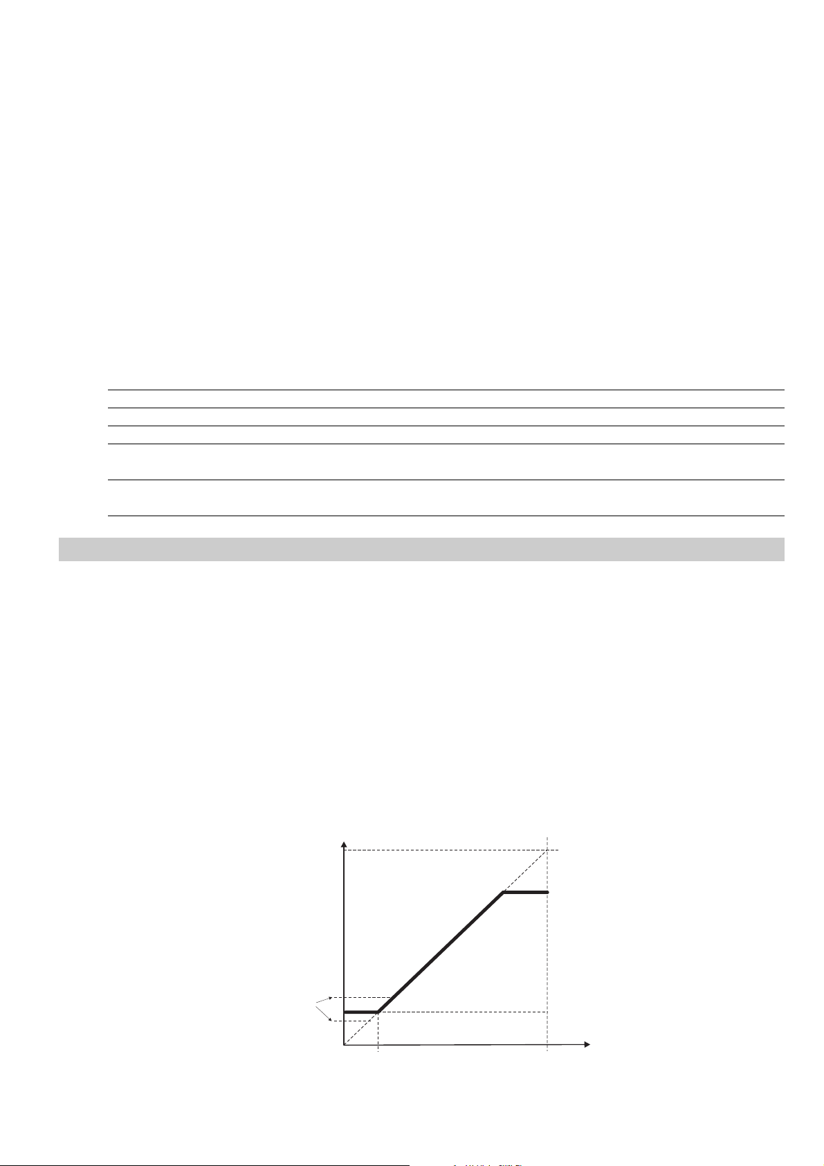
F.011 Motorpot offset (Motorpotentiometer offset)
Giving the RUN command, the motor will rich automatically the frequency set (offset) following the ramp time.
The Motorpot up command will be effect starting from this value, which represent the frequency minimum value
attainable by Morotpot down command.
For further detail see also the section Reference Limits in this chapter.
F.012 Mp output mode (Motorpotentiometer output mode)
It defines positive and/or negative settings of the Motorpotentiometer reference value.
In either setting the HW Reverse command is active (when enabled).
F.013 Mp auto save (Motorpotentiometer auto save)
Enabling this function will cause the Motorpot reference to be continuously saved into non-volatile memory. At
power on, the reference will start from the last saved value.
Disabling this function will cause the Motorpot reference to be always zero after power-on.
Saving drive parameters by command C.000 (or S.901) will not save the Motorpot ref value.
Code Name [Code] & Function. Default MIN MAX Unit Variation IPA
F.000 Motorpot ref 0 0 F.020 Hz 0.01 300
F.010 Acc/Dec time mp 10 0.1 999.9 sec 0.1 301
F.011 Motorpot offset 0 0 50 Hz 0.1 302
F.012 Mp output mode [0] Unipolar 0 0 1 303
[1] Bipolar
F.013 Mp auto save [0] Disable 1 0 1 304
[1] Enable
Reference Limits
F.020 Max ref freq (Maximun reference frequency)
It is the maximum speed for both directions.
This parameter applies to the sum of the different reference value available on the drive (Reference 1 and
Reference 2).
F.021 Min ref freq (Mimimun reference frequency)
It defines the minimum frequency value, under which any regulation with analog or digital references has no
effect.
The START of the motor will be carried out (with the ramp delay) at this frequency value also with null
reference.
As described in the following figure, this behaviour is correlated also to the setting of Min output freq (P.081).
F out
Max output freq (P.080)
Max ref freq (F.020)
(A)
Min output freq (P.081)
Min ref freq (F.021)
(B)
Set frequency
Figure 7.5.2: Min & Max Reference Frequency
User Manual Chapter 7 - Parameters Description 79
Page 80

Drive behaviour around minimum values
P.081 settings in A condition
Giving the RUN command, the motor will rich the frequency set of P.081 (A) without to follow the setting of
acceleration ramp time.
The reference action on the frequency curve, will have effect starting from the setting value of P.081
parameter.
P.081 settings in B condition
Giving the RUN command, the motor will rich the frequency set of P.081 (B) without to follow the setting of
acceleration ramp time.
The increasing of the reference will have effect on the frequency output, starting from the setting value of
F.0 21 parameter (the variation will follow the setting of acceleration ramp time).
The reference action on the frequency curve, will have effect starting from the setting value of F.0 21
parameter.
The Max output freq (P.080) and the Min output freq (P.081) are expressed as percentage of the values of
Max ref freq (F.020).
Code Name [Code] & Function. Default MIN MAX Unit Variation IPA
F.020 Max ref freq (****) 25 500 Hz 0.1 305
F.021 Min ref freq 0 0 F.020 Hz 0.1 306
(****) parameter value depending on drive type.
Reference Sources
F.050 Ref 1 Channel (Reference 1 channel)
F.051 Ref 2 Channel (Reference 2 channel)
As shown in the figure 7.5.1, the Sources from which the 2 speed references are provided and controlled, can be
chosen by following the table below.
The value of the 2 references, will always be an algebric sum.
F.060 Mlt Frq Channel 1 (Multi frequency channel 1)
F.061 Mlt Frq Channel 2 (Multi frequency channel 2)
These parameters allow to select the source, from where the First and Second frequency reference of the
Multispeed function, can be provided and controlled (See figure 7.5.1).
The source can be chosen the following parameters the table below.
Code Name [Code] & Function. Default MIN MAX Unit Variation IPA
F.050 Ref 1 channel [0] Null 3 0 8 307
[1] Analog inp 1 (setting through I.200I.204)
[2] NOT USED
[3] Freq ref x (setting through S.203 or F.100)
[4] Multispeed (setting through F.100F.116)
[5] Motorpotent (setting through F.000F013)
[6] NOT USED
[7] NOT USED
[8] NOT USED
80 Chapter 7 - Parameters Description User Manual
Page 81
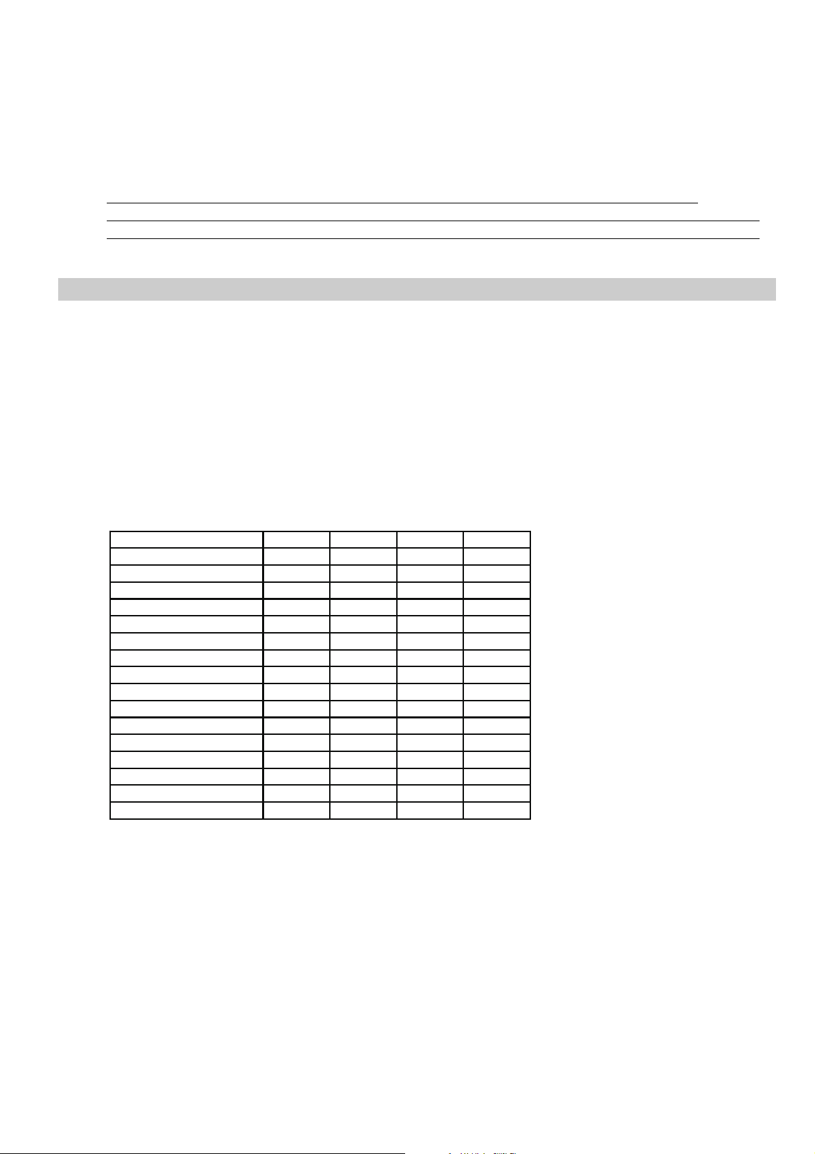
F.051 Ref 2 channel [0] Null 0 0 8 308
[1] Analog inp 1 (setting through I.200I.204)
[2] NOT USED
[3] Freq ref x (setting through F.101)
[4] Multispeed (setting through F.100F.116)
[5] Motorpotent (setting through F.000F013)
[6] NOT USED
[7] NOT USED
[8] NOT USED
F.060 MltFrq channel 1 As for F.050, Ref 1 channel 3 0 7 309
F.061 MltFrq channel 2 As for F.051, Ref 2 channel 3 0 7 310
Multispeed Function
F.100 Frequency Ref 0 (Multi frequency channel 1)
. .
. .
. .
F.115 Frequency Ref 15 (Multi frequency channel 15)
It is possible to select up to 16 frequencies, whose value can be set in these parameters.
The selection of these frequencies can be performed through a binary setting of 4 programmable digital inputs.
The limit of the output frequency will be clamped by Max ref freq (F.020).
The following table describes the basis sequence of the binary setting, for a complete Multispeed selection.
Active Dig ref frequency Freq sel 1 Freq sel 2 Freq sel 3 Freq sel 4
F.100 (Freq Ref 0) 0000
F.101 (Freq Ref 1) 1000
F.102 (Freq Ref 2) 0100
F.103 (Freq Ref 3) 1100
F.104 (Freq Ref 4) 0010
F.105 (Freq Ref 5) 1010
F.106 (Freq Ref 6) 0110
F.107 (Freq Ref 7) 1110
F.108 (Freq Ref 8) 0001
F.109 (Freq Ref 9) 1001
F.110 (Freq Ref 10) 0101
F.111 (Freq Ref 11) 1101
F.112 (Freq Ref 12) 0011
F.113 (Freq Ref 13) 1011
F.114 (Freq Ref 14) 0111
F.115 (Freq Ref 15) 1111
avy4210
The following figure shows the setting of a 8 Multispeed control.
User Manual Chapter 7 - Parameters Description 81
Page 82
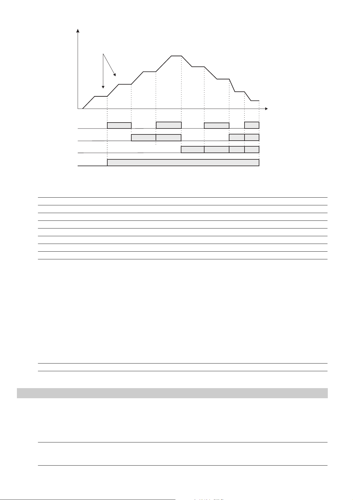
Freq
Selectable through
“MltFreq Channel 1” (F.060)
“MltFreq Channel 2“ (F.061)
Freq ref 3
Freq ref 2
Freq ref 1
Freq ref 0
Freq sel 1
Freq sel 2
Freq sel 3
FWD(RUN) or
REV
Freq ref 4
Freq ref 4
Freq ref 6
Freq ref 7
t
Figure 7.5.3: Multispeed Frequencies
Code Name [Code] & Function. Default MIN MAX Unit Variation IPA
F.100 Frequency ref 0 0 -F.020 F.020 Hz 0.1 311
F.101 Frequency ref 1 0 -F.020 F.020 Hz 0.1 312
F.102 Frequency ref 2 0 -F.020 F.020 Hz 0.1 313
F.103 Frequency ref 3 0 -F.020 F.020 Hz 0.1 314
F.104 Frequency ref 4 0 -F.020 F.020 Hz 0.1 315
F.105 Frequency ref 5 0 -F.020 F.020 Hz 0.1 316
F.106 Frequency ref 6 0 -F.020 F.020 Hz 0.1 317
F.107 Frequency ref 7 0 -F.020 F.020 Hz 0.1 318
F.116 Jog frequency
It is the frequency reference for the JOG speed.
This speed is activated through a programmed digital input.
The RUN command via terminal must not be given. This command will enable the main frequency reference.
The limit of the output frequency will be clamped by Max ref freq (F.020).
The setting of the JOG reference value, can be either positive or negative.
In both the setting the HW Reverse command is active (when enabled).
Code LCD display [Code] & LCD select. Default MIN MAX Unit Variation IPA
F.116 Jog frequency 1 -500 500 Hz 0.1 327
Ramp Configuration
F.200 Ramps resolution
It defines the range and the accuracy with which the ramps time will be set.
Code Name [Code] & Function. Default MIN MAX Unit Variation IPA
F.200 Ramp resolution [0] 0.01s (From 0.01s to 99.99s) 1 0 2 328
[1] 0.1s From (0.1s to 999.99s)
[2] 1s From (1s to 9999s)
82 Chapter 7 - Parameters Description User Manual
Page 83
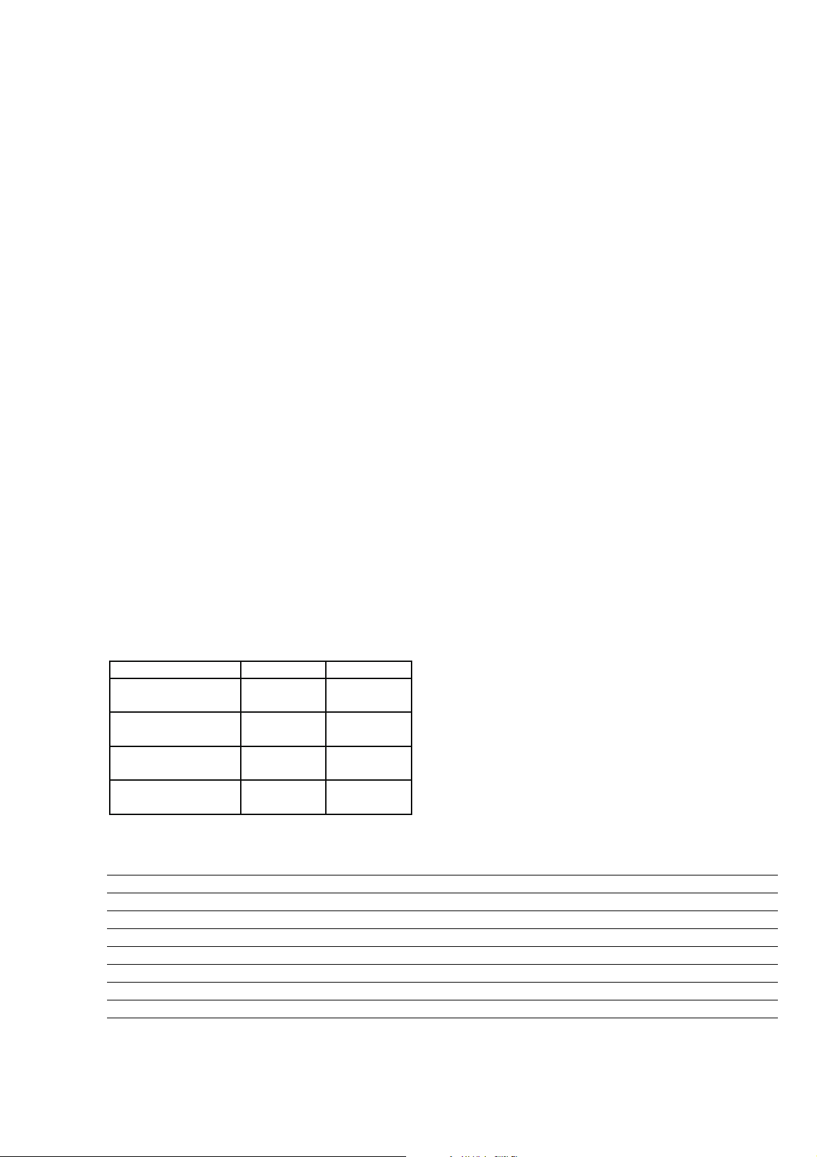
F.201 Acc time 1 (Acceleration time 1)
F.202 Dec time 1 (Deceleration time 1)
F.203 Acc time 2 (Acceleration time 2)
F.204 Dec time 2 (Deceleration time 2)
F.205 Acc time 3 (Acceleration time 3)
F.206 Dec time 3 / FS (Deceleration time 3)
F.207 Acc time 4 (Acceleration time 4)
F.208 Dec time 4 (Deceleration time 4)
NOTE!
When the JOG function is activated, Acc time 4 (F.207) and Dec time 4 (F.208) are selected
automatically.
When the "FAST STOP" is activated (through digital input command), the function is executed with the
DEC TIME 3 delay.
The ramp control can be set for a programmable delay for the acceleration and deceleration times of the drive
reference. This delay time will have to be set on the final system (motor and load), being strictly dependant from
the inertia of the load machine.
The time values are expressed in seconds. The ramps time delay are calculated in accordance with the
Max ref freq (F.020).
It is possible to select up to 4 different time, whose value can be set in these parameters.
The selection of these ramps can be performed through a binary setting of 2 digital inputs, programmed as
Ramp sel 1 and Ramp sel 2.
It is reported below the basis sequence for the full selection.
Active Ramp time Ramp sel 1 Ramp sel 2
F.201 (Acc time 1)
F.202 (Dec time 1)
F.203 (Acc time 2)
F.204 (Dec time 2)
F.205 (Acc time 3)
F.206 (Dec time 3)
F.207 (Acc time 4)
F.208 (Dec time 4)
00
10
01
11
avy4220
Code Name [Code] & Function. Default MIN MAX Unit Variation IPA
F.201 Acc time 1 5 0.1(***) 999.9(***) sec 0.1 (***) 329
F.202 Dec time 1 5 0.1(***) 999.9(***) sec 0.1 (***) 330
F.203 Acc time 2 5 0.1(***) 999.9(***) sec 0.1 (***) 331
F.204 Dec time 2 5 0.1(***) 999.9(***) sec 0.1 (***) 332
F.205 Acc time 3 5 0.1(***) 999.9(***) sec 0.1 (***) 333
F.206 Dec time 3 / FS 5 0.1(***) 999.9(***) sec 0.1 (***) 334
F.207 Acc time 4 / Jog 5 0.1(***) 999.9(***) sec 0.1 (***) 335
F.208 Dec time 4 / Jog 5 0.1(***) 999.9(***) sec 0.1 (***) 336
(***) value depends on the setting of F. 20 0 parameter.
User Manual Chapter 7 - Parameters Description 83
Page 84
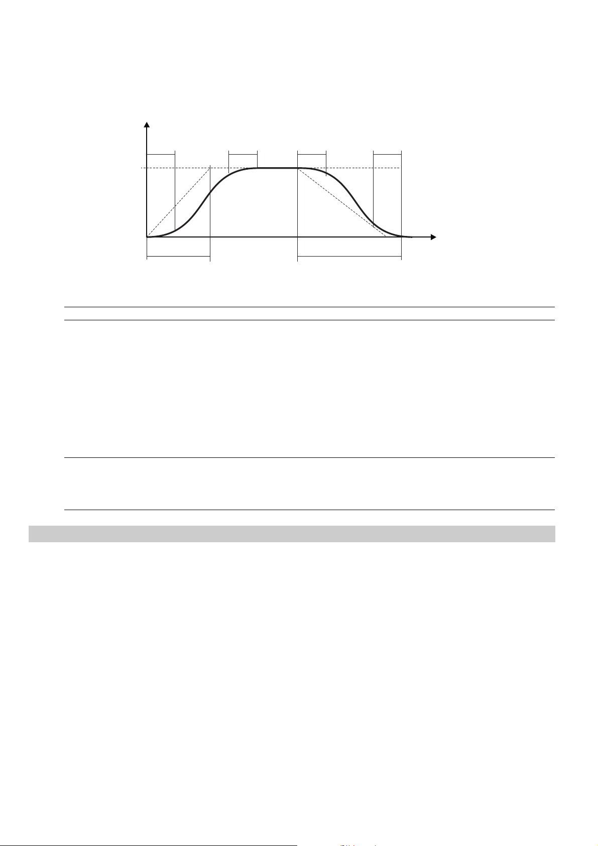
F.250 Ramp S-shape
The S-shaped ramp can be useful to obtain a smooth behaviour of the system during the end of the acceleration
or close to the zero speed during the deceleration.
The value (in seconds) of the S-shaped ramp is added to the ramp time of the linear profile.
The ramp time is thus lengthened by the value of the S-curve constant.
f
F.250
ACC TIME DEC TIME
F.250
Figure 7.5.4: Ramp S-shape
Code Name [Code] & Function. Default MIN MAX Unit Variation IPA
F.250 Ramp S-shape 0 0 10 sec 0.1 337
F.260 Ramp extens src (Ramp extension source)
When an extension of the set ramps time is needed, it can be achieved through the Analog Inputs.
This extension will change linearly according to the value applied on the Analog Input.
The function allows the ramp times extension in a range includes between multiply factor 1 (0V, 0mA o 4mA)
and multiply factor 10 (+/-10V o 20mA).
The parameter select the source from where this function is provided and controlled.
F.250 F.250
t
Code Name [Code] & Function. Default MIN MAX Unit Variation IPA
F.260 Ramp extens src [0] Null 0 0 3 338
Jump Frequencies
F.270 Jump amplitude
F.271 Jump frequency1
F.272 Jump frequency2
In a system composed by motor and drive, at certain frequencies values, it is possible to meet the generation of
noisy vibrations, characterized by mechanical resonances.
Through the parameters F. 27 1 and F. 27 2, it is possible to avoid the working of the inverter around the frequencies
here set.
The parameter F.2 70 defines the tolerance band of the critical zone.
[1] Analog inp 1 (setting through I.200I.204)
[2] Analog inp 2 (setting through I.210I.214)
[3] Analog inp 3 (setting through I.220I.224)
84 Chapter 7 - Parameters Description User Manual
Page 85
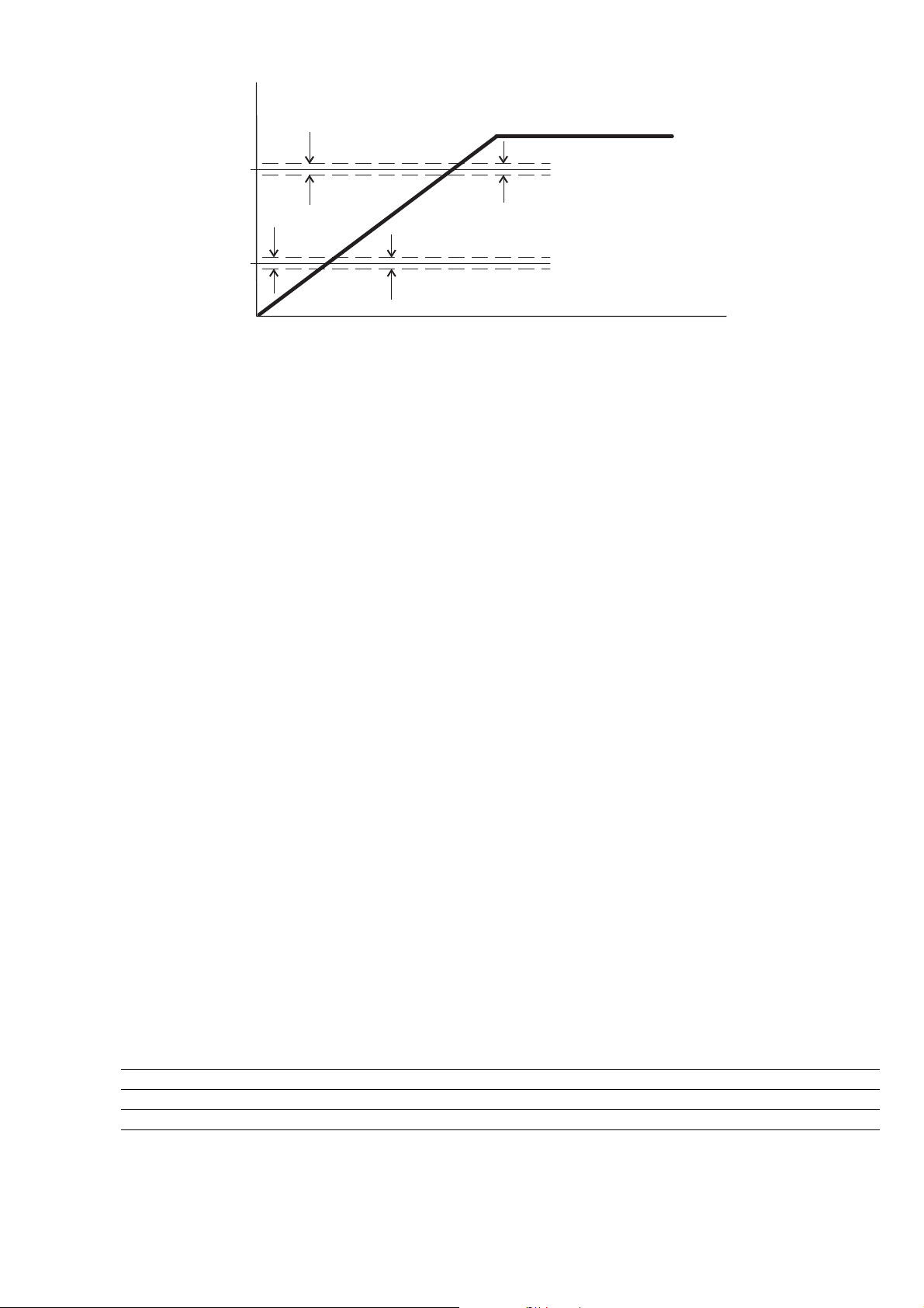
n
F.270
F.270
F.272
F.270
F.270
F.271
t
Figure 7.5.5: Jump Frequencies
When the frequency reference is set to a value within the tolerance band, the frequency output assumes the
following behavior.
Example:
A) Increasing the reference from lower value of F. 27 1 or F. 27 2
F. 27 1 = 30Hz (first forbidden frequency threshold)
F. 27 0 = 1Hz (tolerance band: 29Hz.31Hz)
Setting of frequency reference = 29,5Hz
Frequency output = 29Hz
Setting of frequency reference = 30,5Hz
Frequency output = 29Hz
B) Decreasing the reference from higher value of F.2 71 or F.2 72
F. 27 1 = 30Hz (first forbidden frequency threshold)
F. 27 0 = 1Hz (tolerance band: 29Hz.31Hz)
Setting of frequency reference = 30,5Hz
Frequency output = 31Hz
Setting of frequency reference = 29,5Hz
Frequency output = 31Hz
The user can set any frequency reference, but if its value is within the forbidden range, the inverter will
maintain automatically the speed out the limit of the tolerance band.
During the ramp execution the forbidden frequencies have not any influence, so the output frequency will be
linearly generated.
Code Name [Code] & Function. Default MIN MAX Unit Variation IPA
F.270 Jump amplitude 0 0 100 Hz 0.1 339
F.271 Jump frequency 1 0 0 100 Hz 0.1 340
F.272 Jump frequency 2 0 0 100 Hz 0.1 341
User Manual Chapter 7 - Parameters Description 85
Page 86
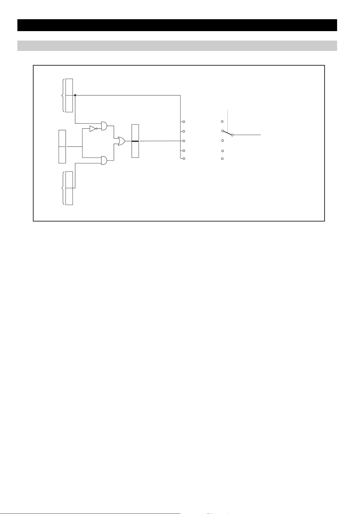
7.6 Menu P - PARAMETERS
Commands
D101
Dig Inp Term
Terminals
Mask
From Serial Link
Dig Inp Exp Term
d121
I400
I410
d102
Dig Inp Virtual
H000
Dig Inp Exp Virtual
H001
d122
P000
Command Source
d100
d120
KEYPAD
0
TERMINAL
1
TERMINAL
2
OR VIRTUAL
SERIAL
3
CONTROL WORD
4
Figure 7.6.1: Basic Commands Logic Selection
To internal decodification
of the regulation
86 Chapter 7 - Parameters Description User Manual
Page 87
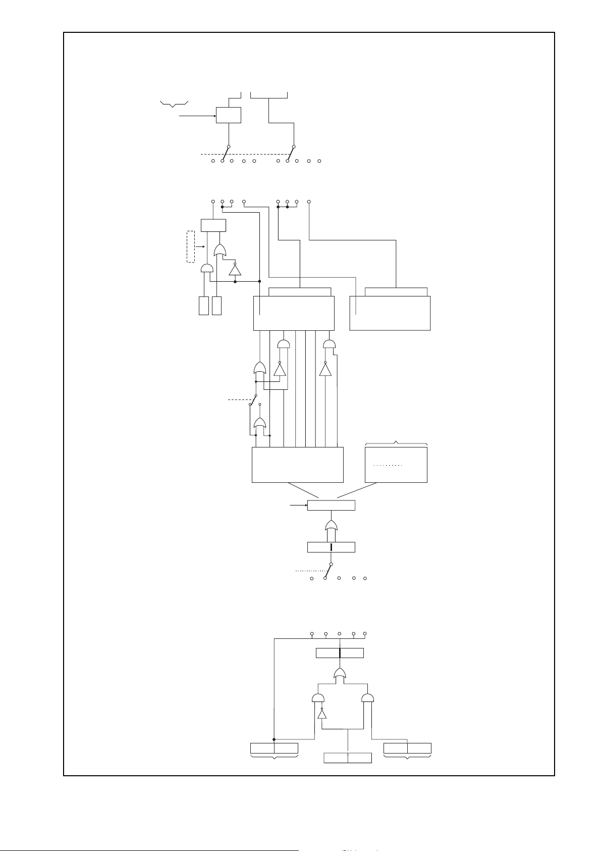
0 : Not active
P003
1 : Active (Default)
P000
CMD
CMD_RUN
CMD_REV
CMD_JOG
CMD_MOTOR DCB
CMD_PINKUP
CMD_RESET
Safe Start
Logic
SOURCE
OR VIRTUAL
1 TERM.
2 TERMINAL
0 KEYPAD
R
RUN KEYPAD
RUN
S
STOP
0 = Modalità RUN/REV
1 = Modalità FWD/REV
P001
3 SERIAL
0
4 RESERVED
RUN
1
DI RUN/FWD
REV
DI REV
OR VIRTUAL
1 TERM.
2 TERMINAL
0 KEYPAD
JOG
DI JOG
MOTOR DCB
MOTOR DCB
PICKUP
PICKUP
3 SERIAL
ALARM RESET
ALARM RESET
4 RESERVED
ENABLE_NC
ENABLE
ENABLE_NO
RUN
REV
FRQ SEL1
JOG
PICKUP
MOTORDCB
To drive
regulation
FRQ SEL..
ALARM RESET
(See Digital
Serial link commands
Input List)
ENABLE
Decodification
Dig Inp
Dig Inp Exp
P000
Command Source
TERMINAL
OR VIRTUAL
243
I400
SERIAL
Mask
(RESERVED)
d120
d102
I410
d101
KEYPAD
TERMINAL
0
1
d100
Dig Inp Exp Term
Dig Inp Term
d121
Terminals
Figure 7.6.2: Main Commands Logic Selection
Dig Inp Virtual
H000
Dig Inp Exp Virtual
H001
From Serial Link
d122
User Manual Chapter 7 - Parameters Description 87
Page 88

P.000 Cmd source sel (Command source selection)
It defines the selection mode for the main commands START and STOP.
P.000 = 1 START & STOP via terminals
In this configuration the commands are active through the terminals.
The motor START can be performed applying the specific logic level (high level +15V , terminal 4), to
the Digital Input 1 (terminal 5), factory set as RUN.
If this connection is removed, the motor will STOP with the set ramp time.
NOTE!
NOTE!
P.000 = 2 Main commands & I/Os setting via virtual channels or terminals
After a cycle of main supply voltage, the drive can be started only according to the settings of
P.003 Safety parameter, which allows the Start/Stop commands to respond to Edge or Level sensitive
signals.
The command Drive enable available as a selection of the digital inputs, adds additional safety logic
for the motor running sequences.
The releasing of it, will produce a coast to stop of the motor. (see chapter INTERFACE, section
Digital inputs).
In this configuration, the commands programmable on the digital inputs or the signalling of the
digital and analog outputs, can be assigned as follows:
Complete selection via serial line or fieldbus as Virtual setting
Complete selection via Terminals setting
Mix of Virtual and Terminal selection
NOTE!
The requirements of commands via terminal strip is depending by virtual I/O settings.
Further information about this function, can be found in the chapters:
INTERFACE section Enabling Virtual I/O
Commands addressing is described in the chapter HIDDEN
P.000 = 3 START & STOP & main commands via Serial line (SERIAL)
It define the selection of the main commands exclusively via serial line or filedbus.
NOTE!
P.000 = 4 Main commands & I/Os setting through Control word bits of Profidrive
Commands via terminal strip are not required.
Further information about the serial line, can be found in the chapters:
INTERFACE section Serial configuration
Commands addressing is described in the chapter HIDDEN, section Commands for serial link.
It allows the selection of the main commands exclusively via Profidrive (optional field bus).
P.001 RUN input config (RUN input configuration)
Definition of the RUN and Reverse logic control.
P.001 = 0
FWD (clockwise direction) with terminal RUN = ON
REV (anti-clockwise direction) with terminal RUN = ON and terminal REV = ON
P.001 = 1
FWD (clockwise direction) with terminal RUN = ON
REV (anti-clockwise direction) with terminal RUN = OFF and terminal REV = ON
88 Chapter 7 - Parameters Description User Manual
Page 89

P.002 Reversal enable
Block of the command direction of the motor.
P.002 = 0
REV (anti-clockwise direction) DISABLED
P.002 = 1
REV (anti-clockwise direction) ENABLED
The function will be applied at any kind of REV logical command (digital input, negative reference and serial
line).
P.003 Safety
The parameter defines the RUN (or REVERSE) command behavior at the drive power on:
P.003 = 0 RUN command via a Level sensitive signal.
At the drive power on, the starting of the motor is allowed when the RUN command is already present on
terminal strip.
P.003 = 1 RUN command via an Edge sensitive signal.
At the drive power on, the starting of the motor is not allowed when the RUN command is already present on
terminal strip.
The starting of the motor can be execute cycling RUN command.
Mapping a digital output as "Ready", the drive state condition can be displayed according to the above
parameter setting.
P.004 Stop mode
Motor stop control function.
P.004 = 0 The control sets the motor ramp deceleration up to 0 Hz.
P.004 = 1 The control cuts off the output voltage, so the motor coasts to stop.
Code Name [Code] & Function. Default MIN MAX Unit Variation IPA
P.000 Cmd source sel [0] Keypad 1 0 4 400
P.001 RUN input config [0] Run / Rev 0 0 1 401
P.002 Reversal enable [0] Disable 1 0 1 402
P.003 Safety [0] OFF 1 0 1 403
P.004 Stop mode [0] In ramp 0 0 1 493
[1] Terminals
[2] Virtual
[3] Serial
[4] Control word
[1] Fwd / Rev
[1] Enable
[1] ON
[1] Ramp to stop
Power Supply
P.020 Mains voltage
Rated value of the line voltage [V
The undervoltage trip function is based on this value (see also chapter PARAMETERS, function Undervoltage
configuration).
P.021 Mains frequency
Rated value of the line voltage frequency [Hz].
User Manual Chapter 7 - Parameters Description 89
rms
].
Page 90
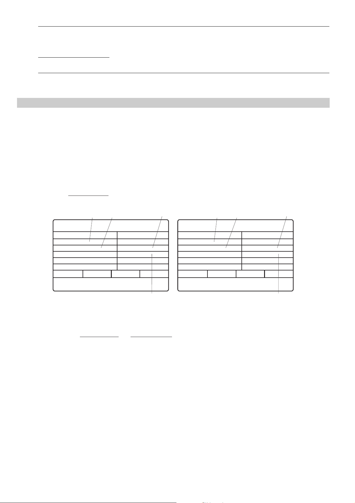
Code LCD display [Code] & LCD select. Default MIN MAX Unit Variation IPA
P.020 Mains voltage 110 (****) 230 575 V 404
220
230
240
P.021 Mains frequency 50 (****) 50 60 Hz 405
60
(****) parameter value depending on drive type.
Motor Data
P.040 Motor rated curr (Motor rated current)
Rated current [A
7.6.3).
In case of control with multiple motors, enter a value equal to the sum of the rated currents of all the motors.
Do not perform any self tune.
P.041 Motor pole pairs
Pole pairs of the motor. The setting of this data, can be easily calculated with the following formula:
N[rpm] =
] of the motor at rated kilowatt/horsepower and voltage (given on the nameplate, see figure
rms
60 [s] x f [Hz]
2p [polepairs]
S.101 (P.062)
Motor & Co.
Type: ABCDE
Motor: 3 phase
Rated voltage
Rated power
Rated speed (n )
IP54
Made in ..............
N
50 Hz
400 V
3kW
1420 rpm
Iso Kl F
S.100 (P.061)
S1
IEC 34-1 / VDE 0530
Nr
.
I nom
Power factor
12345-91
6.7 A
0.8
S.152 (P.042)
S.150 (P.040)
Motor & Co.
Type: ABCDE
Motor: 3 phase
Rated voltage
Rated power
Rated speed (n )
IP54
Made in ..............
S.101 (P.062)
60 Hz
575 V
2Hp
1750 rpm
N
Iso Kl F
S.100 (P.061)
S1
IEC 34-1 / VDE 0530
Nr
.
I nom
Power factor
Efficiency
12345-91
2A
0.83
86.5
S.152 (P.042)
S.150 (P.040)
Figure 7.6.3: Motor Nameplate (Example: kW rating for 400V motor and Hp rating for 575V motor)
Example: calculation of the pole pairs of a motor having the data shown in the above label:
p [polepairs] =
60 [s] x f [Hz]
n [rpm]
N
60 [s] x 60 [Hz]
==2
1750 [rpm]
the value to set in the parameter P.0 4 1 is "2".
Where: p = motor pole pairs; f = rated motor frequency (P. 0 6 2 ); nN = rated motor speed (see figure 7.6.3)
P.042 Motor power fact (Motor power factor)
Motor power factor (given on the nameplate, see figure 7.6.3).
A signalling of the "negative power factor" condition is available on the digital output as "Neg pwr fact ".
P.043 Motor stator R (Motor stator Resistance)
Measurements of the stator resistance of the motor.
This value will be automatically updated, after performing the self tune procedure.
90 Chapter 7 - Parameters Description User Manual
Page 91
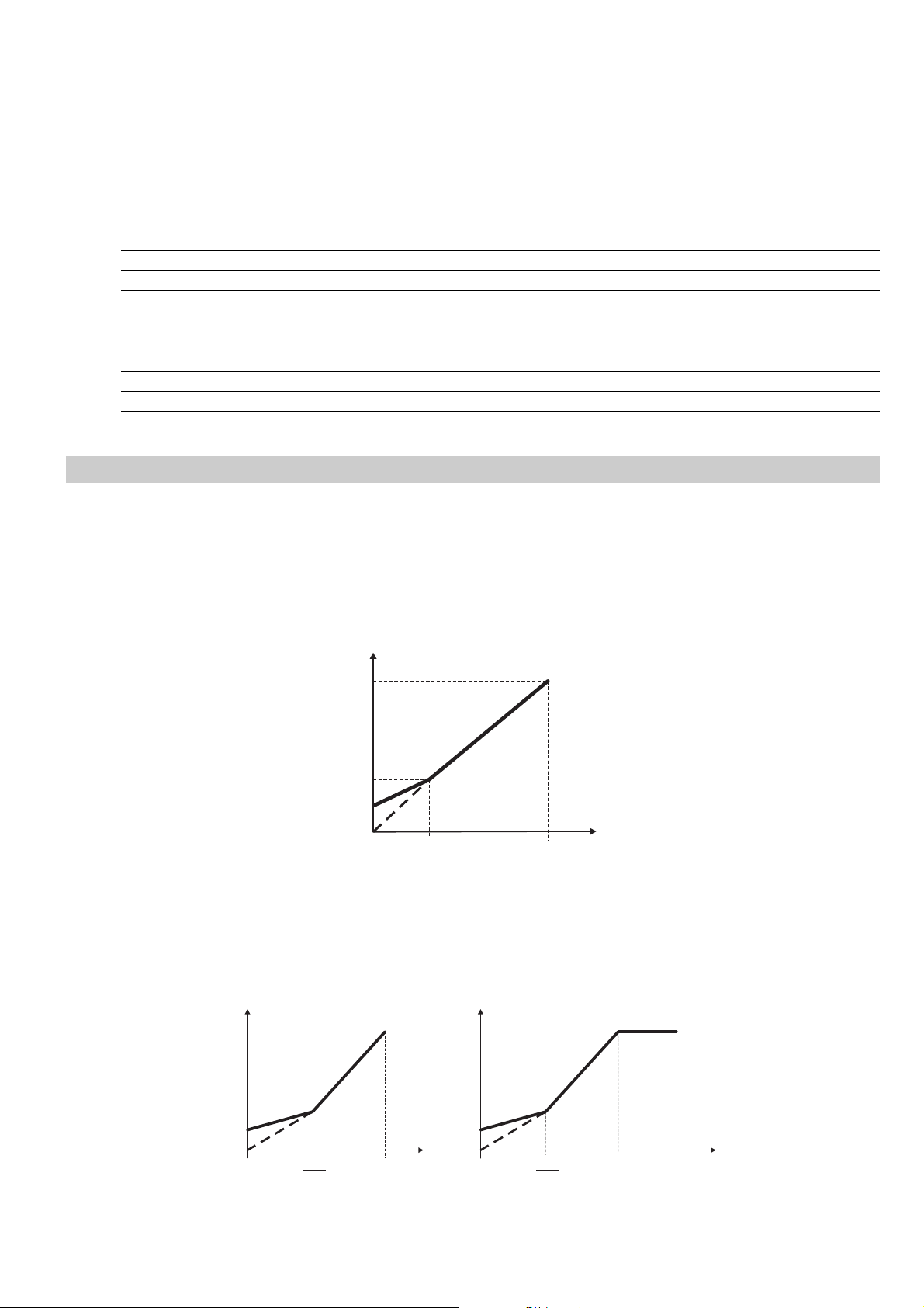
P.044 Motor cooling
Setting of the type of cooling of the motor connected.
P.045 Motor thermal K (Motor thermal costant)
Thermal characteristic of the motor connected.
The data is normally provided by the motor manufacturer, as the time needed to reach the maximum
temperature at rated current.
Code Name [Code] & Function. Default MIN MAX Unit Variation IPA
P.040 Motor rated curr (*) (*) (*) A 0.1 406
P.041 Motor pole pairs (*) 1 60 407
P.042 Motor power fact (*) 0.01 1 0.01 408
P.043 Motor stator R (*) 0 99.99 ohm 0.01 409
P.044 Motor cooling [0] Natural 0 0 1 410
[1] Forced
P.045 Motor thermal K 30 1 120 min 411
P.046 Motor nominal slip (*) 0 25 % 501
P.047 Motor nominal eff (*) 50 100 % 504
V/F Curve
P.060 V/f shape
Se lection of the c urve for th e V/F rati o.
P.060 = 0 (Custom )
The intermediate values of voltage and frequency, are defined by the parameters P.0 6 3 and P. 0 6 4 as well as
the link of the manual Boost on the characteristic.
P.060 = 1 (Linear )
The factory setting provides a Linear V/F ratio, having the middle points fixed by the half value of P. 0 6 3 and
P. 0 6 4 .
P.061
P.063
P.120
V
P.064
Figure 7.6.4: Custom V/F shape
P.062
F
(F.020)
P.061
P.120
V
P.062
2
P.062
(F.020)
F
(n)
P.061
P.120
V
P.062
2
P.062
F.020
F
(n)
Figure 7.6.5: Linear V/F shape
User Manual Chapter 7 - Parameters Description 91
Page 92
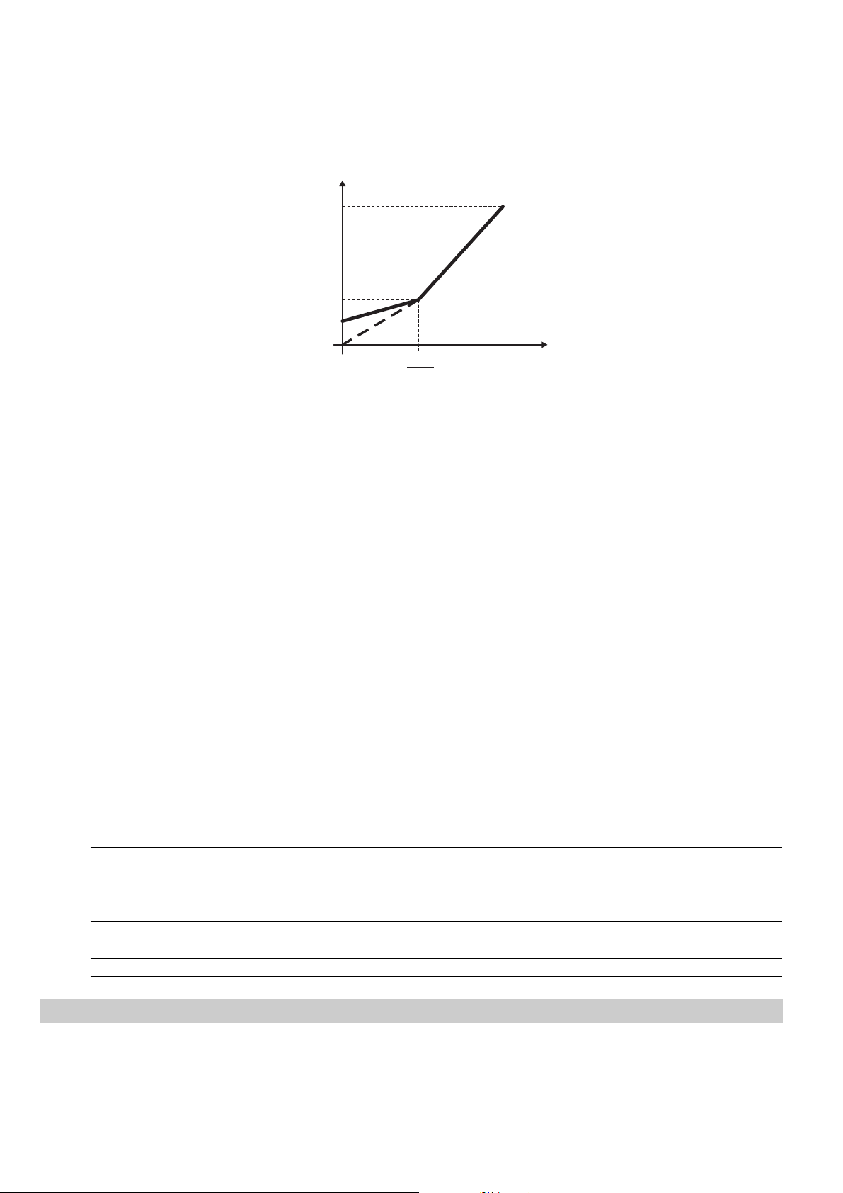
P.060 = 2 (Quadratic )
The Quadratic characteristic is useful when a pump or fan has to be controlled (load where the torque is
proportional to the speed squared).
The factory setting, when this ratio is selected, provides a setting of P. 0 6 3 equal to the 0,25% the Max output
voltage, at a frequency equal to 50% of P. 0 6 2 .
V
P.061
(P.061 x 0.25)
P.120
P.062
Figure 7.6.6: Quadratic V/F shape
P.061 Max out voltage (Maximum output voltage)
Maximum value of the voltage applied to the motor (normally set as the nameplate, see figure 7.6.3).
P.062 Base frequency
Rated frequency of the motor (given on the nameplate, see figure 7.6.3).
It represents the working frequency of the drive, at which the Max out voltage is associated (P. 06 1 ).
P.063 V/f interm volt (V/f intermediate voltage)
Intermediate "voltage" value of the V/F characteristic selected.
P.064 V/f interm freq (V/f intermediate frequency)
Intermediate "frequency " value of the V/F characteristic selected.
NOTE!
When custom V/f shape is selected (P. 0 6 0 = 0):
P. 0 6 4 parameter represents the return point of the output voltage, on the linear characteristic of V/f
ratio (see figure 7.6.4).
P.062
F
2
(F.020)
Code Name [Code] & Function. Default MIN MAX Unit Variation IPA
P.060 V/f shape [0] Custom 1 0 2 412
[1] Linear
[2] Quadratic
P.061 Max out voltage (**) 50 (**) V 1 413
P.062 Base frequency (**) 25 500 Hz 0.1 414
P.063 V/f interm volt (**) 0 P.061 V 415
P.064 V/f interm freq (**) 1 P.062 Hz 0.1 416
Ouput Frequency Limit
P.080 Max output freq (Maximun output frequency)
It is the maximum level of the output frequency, expressed as percentage of Max ref freq (F.020).
92 Chapter 7 - Parameters Description User Manual
Page 93

This parameter takes into account the sum of all the reference frequencies and frequency variables of the drive,
deriving by :
Speed references, Slip compensation, PID regulator
P.081 Min output freq (Minimun output frequency)
Minimum value of output frequency, under which no reference regulation has effect.
It is expressed as percentage of Max output freq (P.080).
The parameter is correlated to the Min ref freq (F.021), as reported in the figure below.
F out
Max output freq (P.080)
Max ref freq (F.020)
(A)
Min output freq (P.081)
Min ref freq (F.021)
(B)
Set frequency
Figure 7.6.7: Min & Max Reference Frequency
A signalling of the "output frequency" status is available on the digital output as "Out freq<set".
Code Name [Code] & Function. Default MIN MAX Unit Variation IPA
P.080 Max output freq 100 0 110 % of F.020 417
P.081 Min output freq 0.0 0.0 25.0 % of F.020 0.1 418
Slip Compensation
P.100 Slip compensat (Slip compensation)
If an induction motor is being used, the mechanical speed will vary with the load due to the slip of the motor.
In order to adjust for this speed error the slip compensation can be used.
During this calibration, make sure that the drive is not in a current limit condition.
If this compensation is set too high it can cause instability.
The changing will be carried out as a percentage of the nominal slip, calculated when set the motor plate date.
The Slip compensation will act directly on the output frequency of the drive. For this purpose the parameter
Max output freq (P.080) expressing the percentage of the Max ref freq (F.020), has to be set to a value
including:
Max ref freq value + Slip compensat value.
See chapter "PARAMETERS", section "Output Frequency Limit".
The Slip compensation must be disabled when a multiple motor connection is being used.
P.101 Slip comp filter (Slip compensation filter)
It is the response time (in seconds) for the reaction of the function.
Increasing this value helps damping oscillations that may arise with load steps (especially negative ones).
User Manual Chapter 7 - Parameters Description 93
Page 94
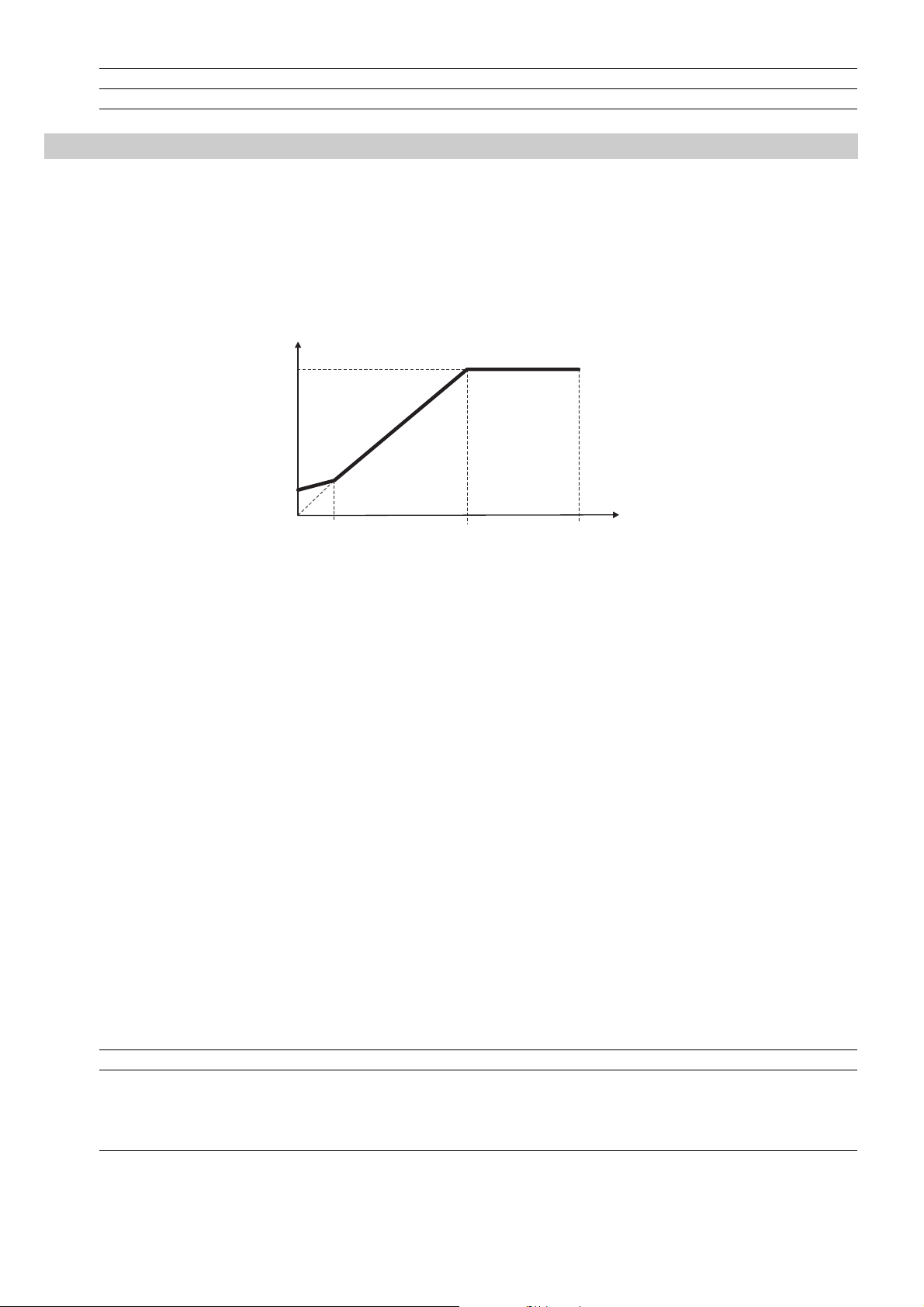
Code Name [Code] & Function. Default MIN MAX Unit Variation IPA
P.100 Slip compensat 0 0 250 % 419
P.101 Slip comp filter 0.1 0 10 sec 0.1 420
Boost
P.120 Manual boost [%]
The resistive impedance of the stator windings causes a voltage drop within the motor, which result in a reduction
in torque in the lower speed range.
Compensation can be made for this effect by boosting the output voltage.
This compensation is carried out continuously across the whole speed range in proportion to the output current
but it is most effective at low speed.
V
P.061
P.120
P.064
P.062
F.020
Figure 7.6.8: Manual Boost Voltage
The setting is in percentage of the Max out voltage (P.061).
P.121 Boost factor src (Factor extension source of manual Boost)
The manual Boost level can be linearly regulated through an analog reference signal.
The regulation of the Boost level will be between 0% (setting the inputs at 0V - 0mA - 4mA) and 100% of the
percentage value set in P.120 (+/- 10V - 20mA).
This parameter selects the source from where this function is provided and controlled.
P.122 Auto boost en (Automatic boost enabling)
The boost can be automatically controlled by the enabling of this parameter. The control is continuously carried
out in the whole speed range.
NOTE!
The automatic boost is automatically calculated during the execution of drive/motor self tuning (P. 0 43
parameter). It is anyway possible to obtain an "Oveboost" at low speed, increasing the value of the
manual boost (P.120 parameter).
F
(n)
The Auto boost must be disabled when a multiple motor connection is being used.
Code Name [Code] & Function. Default MIN MAX Unit Variation IPA
P.120 Manual boost [%] 1 0 25 % of P.061 0.1 421
P.121 Boost factor src [0] Null 0 0 3 422
[1] Analog inp 1 (setting through I.200I.204)
P.122 Auto boost en [0] Disable 1 0 1 423
[1] Enable
94 Chapter 7 - Parameters Description User Manual
Page 95

Automatic Flux Regulation
P.140 Magn curr gain (Magnetizing current gain)
The magnetizing current of the motor, has approximately the no load current value at rated voltage and frequency.
A control of this variable is performed with the changing of its gain. .
The benefit is substantially an availability of motor higher torque at low speeds, obtained with a modality similar
to the "boost voltage" function.
A too high setting can cause undesired oscillation.
N
OTE!
Code Name [Code] & Function. Default MIN MAX Unit Variation IPA
P.140 Magn curr gain 0 0 100 % 0.1 424
It is not reconmmended to use this function if sustained operation below 1 Hz is required.
Anti Oscillation Function
P.160 Osc damping gain (Anti Oscillation damping gain)
The parameter (current symmetry) is used to eliminate any oscillation or beat in the motor current resulting from
tolerances or configurations capable of generating oscillations within the Inverter/cable/ motor system.
The "0" value set at the factory is effective in many cases.
If necessary this value can be altered (0...100) to provide adaptation to the application in question.
During the calibration of the optimum value it is recommended to set the variations of this parameter with slight
increases.
The frequency operation range is around 10Hz30Hz .
Code Name [Code] & Function. Default MIN MAX Unit Variation IPA
P.160 Osc damping gain 0 0 100 425
SW Current Clamp
P.180 SW clamp enable (Software current clamp enabling)
To optimize the performance of the inverter, it is necessary to be able to accelerate and decelerate during the
whole ramp time with the maximum current that the inverter can supply to the motor.
The setting of very short ramp times, that would cause an exceeding of the allowable current limits of the drive,
activates the "Current Clamp"circuit avoiding to reach the overcurrent limits and the consequent "OC" trip.
The intervention of the "Current Clamp" circuit, has as consequence an increase of the real time in which the
final speed is obtained.
It is anyway possible the disabling of the function, setting this parameter at zero.
Code Name [Code] & Function. Default MIN MAX Unit Variation IPA
P.180 SW clamp enable [0] Disable (not active) 1 0 1 426
[1] Enable (active)
Current Limit
The drive is provided with an active current limited function.
It is possible to select different current limits, during the ramps or at steady state.
Current limitation is achieved by a PI regulator effect on speed reference (see P.2 0 6 parameter).
P.200 En lim in ramp (Enabling limit in ramp)
P.200 = 0 Function disabled.
User Manual Chapter 7 - Parameters Description 95
Page 96

P.200 = 1 Enabling of the current limit control during the ramps.
P.200 = 2 Ramp-curr ctrl
During speed acceleration or deceleration, if the current value exceeds the setting of P. 2 0 1 (Current
limit during the ramp), the ramp stage will be momentary blocked and the speed kept at the value
reached in this moment.
When the current will decrease again below this limit, the ramp will be restarted with the profile set.
The ramp time is thus lengthened by the execution of this control.
P.201 Curr lim in ramp (Current limit in ramp)
Value of the current limit during the ramps.
It is as percentage of the nominal current of the drive (see also parameter d.950, chapter DISPLAY).
P.202 En lim in steady (Enabling limit in steady)
Enabling of the current limit control during the ramps.
P.203 Curr lim steady (Current limit in steady)
Value of the current limit during steady state.
It is as percentage of the nominal current of the drive (see also parameter d.950, chapter DISPLAY).
P.204 Curr ctrl P-gain (Current control proportional gain)
Proportional gain of the current regulator.
a setting too low could have a slow reaction on the regulation response.
a setting too high could can have a too fast reaction with consequent oscillations of the system.
P.205 Curr ctrl I-gain (Current control integral gain)
Integral gain of the current regulation.
a setting too low could have a slow reaction on the regulation response.
a setting too high could can have a too fast reaction with consequent oscillations of the system.
P.206 Curr ctr feedfwd (Current control feed forward)
As described in the figure below, the setting of the feed-forward, allows to avoid the drive trip for overcurrent
(OC) during fast acceleration of the load.
When the current exceeds the value of Curr lim in ramp, a quick frequency step (percentage of the motor
rated slip), is automatically sutracted to the reference.
In this case the ramp is extended in order to keep the current level under this limit.
A shortening of the extended ramp time, can be of course achieved excluding the load.
This function operates only during the ramp time (not in steady state).
96 Chapter 7 - Parameters Description User Manual
Page 97
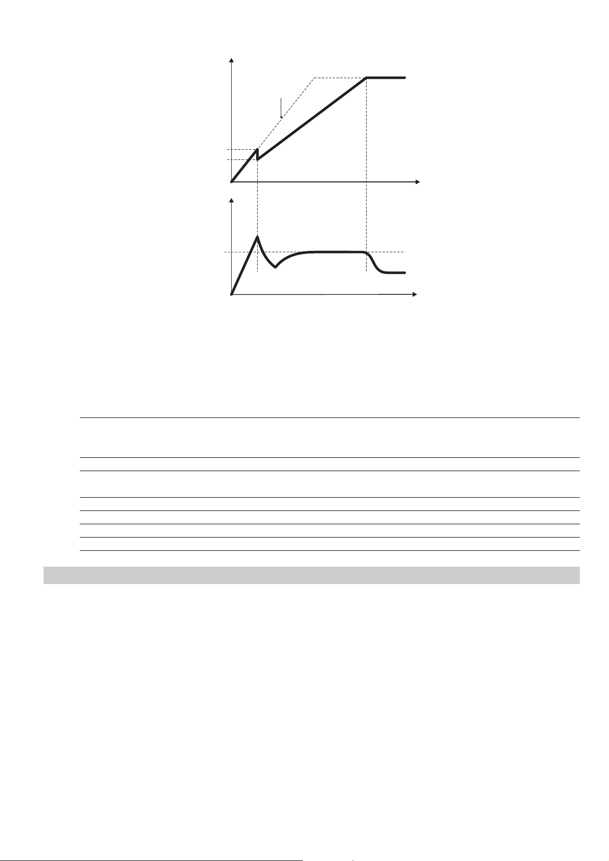
P.206
n
Ramp Profile
Set
I
t
P.201
t
Figure 7.6.9: Current Limit Control in Ramp
A signalling of the "current limit" condition is available on the digital output as "Current limit".
A signalling of the "overcurrent" condition is available on the digital output as "Alarm state".
Code Name [Code] & Function. Default MIN MAX Unit Variation IPA
P.200 En lim in ramp [0] None 0 0 2 427
[1] PI Limiter
[2] Ramp freeze
P.201 Curr lim in ramp 170 20 170 % I nom 428
P.202 En lim in steady [0] Disable 0 0 1 429
[1] Enable
P.203 Curr lim steady 170 20 170 % of I nom 430
P.204 Curr ctrl P-gain 30.0 0.1 100 % 0.1 431
P.205 Curr ctrl I-gain 10.0 0.1 100 % 0.1 432
P.206 Curr ctr feedfwd 0 0 250 % 433
DC Link Limit
The function when enabled, performs a control on the voltage level of the DC link bus capacitor.
During fast deceleration if the load has a big inertia, the DC link value can suddenly increase close to the alarm
threshold. In this case the ramp is controlled keeping the voltage level within safety values.
Consequently the deceleration ramp time is automatically extended, in order to achieve the deceleration of the load,
trying to avoid an eventual block for "overvoltage" (OV alarm).
As for the current limiter, the DC-Link controller is PI-based, with the addition of a programmable feed forward term.
P.220 En DC link ctrl (Enabling DC link control)
P.220 = 0 Function disabled.
P.220 = 1 Enabling of the DC link control function.
P.220 = 2 DC-Ramp ctrl
During fast deceleration, if the DC link level increase close to the alarm threshold, the ramp stage
will be momentary blocked and the speed kept at the value reached in this moment.
When the DC link level, will decrease again within the internal safety values, the ramp will be
restarted with the profile set. The ramp time is thus lengthened by the execution of this control.
User Manual Chapter 7 - Parameters Description 97
Page 98
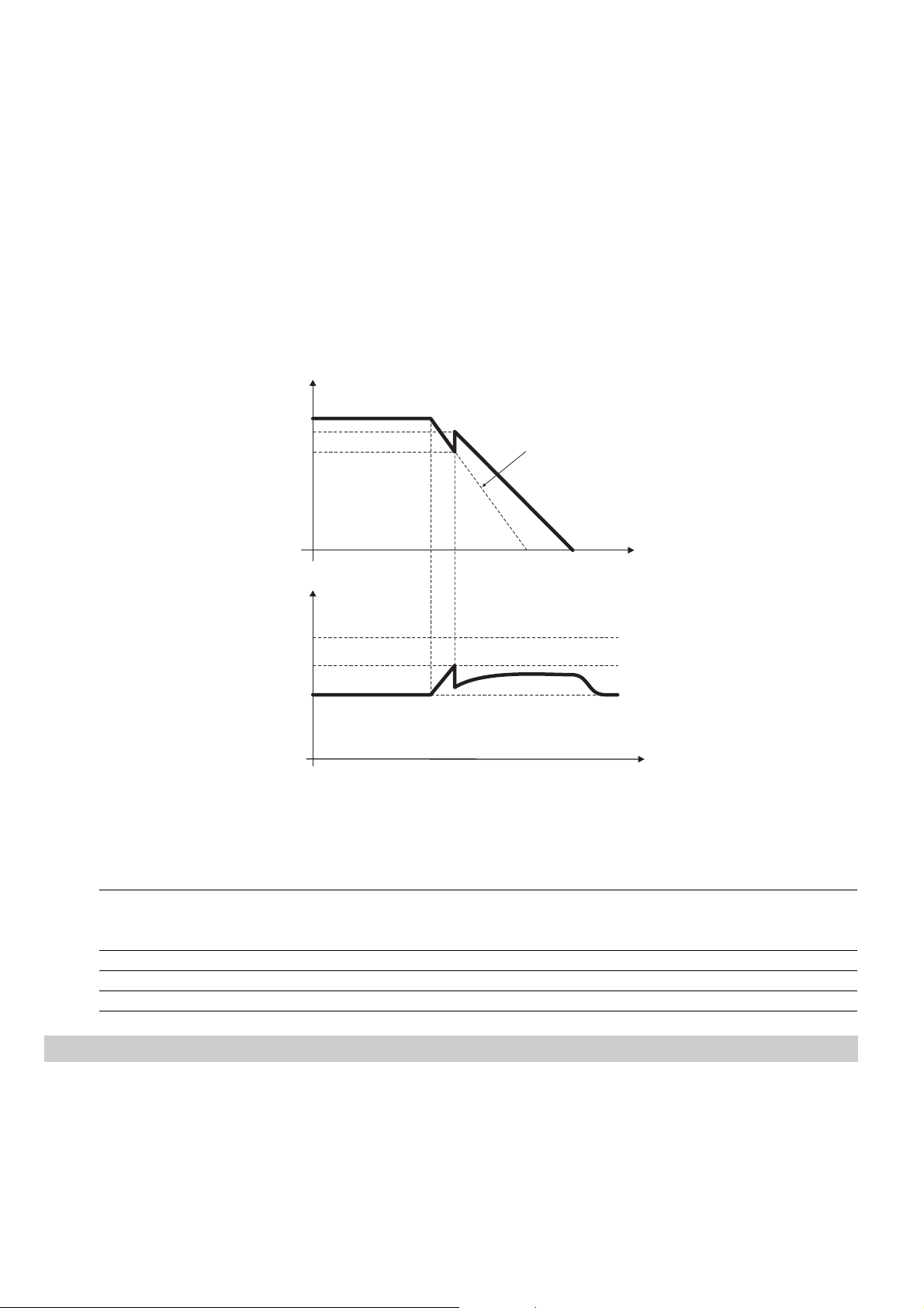
P.221 DC-lnk ctr Pgain (DC link control proportional gain)
Proportional gain of the DC link control regulation.
- a setting too low could have a slow reaction on the regulation response.
- a setting too high could have a too fast reaction with consequent oscillations of the system.
P.222 DC-lnk ctr Igain (DC link control integral gain)
Integral gain of the DC link control regulation.
- a setting too low can have a slow reaction on the regulation response.
- a setting too high can have a too fast reaction with consequent oscillations of the DC link.
P.223 DC-link ctr FF (DC link control feed forward)
As described in the figure beow, this is the setting of the feed-forward for the DC control function.
At the increasing of the DC link level, a quick frequency step (percentage of the motor slip), is automatically
added to the reference. The voltage level decreases toward its rated value.
n
Ramp Profile
Set
t
t
V
Dclink
0V Thr
RATED
P.223
Safety
Dclink
Figure 7.6.10: DC Link Voltage Control
The "overvoltage " alarm will be displayed with the message "OV".
A signalling of the "DC link" status is available on the digital output as "DC bus limit".
Code Name [Code] & Function. Default MIN MAX Unit Variation IPA
P.220 En DC link ctrl [0] None 0 0 2 434
[1] PI Limiter
[2] Ramp freeze
P.221 DC-lnk ctr Pgain 20.0 0.1 100 % 0.1 435
P.222 DC-lnk ctr Igain 2.0 0.1 100 % 0.1 436
P.223 DC-link ctr FF 0 0 250 % 437
Over Torque Alarm Configuration
The torque of the motor (active current) can be monitored through this function.
In particular the overtorque condition and the behaviour of the drive itself, are manageable by these parameters.
P.240 OverTorque mode
It defines the status of the drive during its overtorque condition.
P.240 = 0 Overtorque signalling during ramps and at steady state. No alarm will be generated.
98 Chapter 7 - Parameters Description User Manual
Page 99

P.24 0 = 1 Overtorque signalling only at steady state. No alarm will be generated.
P.240 = 2 Overtorque alarm and signalling during ramps and at steady state.
P.240 = 3 Overtorque alarm and signalling only at steady state.
P.24 1 OT curr l i m t hr (Overtorque current limit threshold)
Overtorque signalling threshold.
It is a percentage of the Motor rated curr (P.040).
P.242 OT level fac src (Overtorque level factor source)
The overtorque level can be linearly regulated through an analog reference signal.
The regulation of this level will be performed between 0% (setting the inputs at 0V - 0mA - 4mA) and 100% of
the percentage value setted with P.241 (+/- 10V - 20mA).
This parameter selects the source from where this function is provided and controlled.
P.242 = 0 OFF
P.242 = 1 Analog Inp 1 (setting through I.200I.204)
P.242 = 2 Analog Inp 2 (setting through I.210I.214)
P.242 = 3 Analog Inp 3 (setting through I.220I.224)
P.243 OT signal delay (Overtorque signalling delay)
Delay time for the alarm signalling.
The alarm will be displayed with the message "Ot"
A signalling of the "overtorque" condition is available on the digital output as "Out trq>thr".
Code Name [Code] & Function. Default MIN MAX Unit Variation IPA
P.240 OverTorque mode [0] No Alm,Chk on 0 0 0 3 438
[1] No Alm,Chk ss
[2] Alm always
[3] Alm steady st
P.241 OT curr lim thr 110 20 200 % 439
P.242 OT level fac src [0] Null 0 0 3 440
[1] Analog inp 1
[2] Analog inp 2
[3] Analog inp 3
P.243 OT signal delay 0.1 0.1 25 sec 0.1 441
Motor Overload Configuration
P.260 Motor OL prot en (Motor overload protection enabling)
Enabling of the motor thermal protection.
The control is performed as an I2t, calculated on the basis of the setting of
Motor rated curr (P.040) and Motor thermal K (P.045).
An overload of the motor, will cause the intervention of the alarm "Motor overload".
The parameter d.052 (menu DISPLAY), is the monitoring of the motor overload level.
A value of 100% represent the threshold for the alarm.
The alarm will be displayed with the message "OLM"
A signalling of the "overcurrent" condition is available on the digital output as "Alarm state".
Code Name [Code] & Function. Default MIN MAX Unit Variation IPA
P.260 Motor OL prot en [0] Disable 1 0 1 444
[1] Enable
User Manual Chapter 7 - Parameters Description 99
Page 100

BU Configuration
P.280 Brake res OL en (Braking resistor overload protection enabling)
Enabling of the thermal protection of the braking resistance.
The protection efficiency is dependant on the accuracy of the parameters concerning the rated value of the
braking resistance.
An overload of the braking resistor, will cause the intervention of the alarm "Braking resistor overload".
P.281 Brake res value (Braking resistor value)
Rated Ohm value of the braking resistance connected.
P.282 Brake res power (Braking resistor power)
Rated power of the braking resistance connected.
P.283 Br res thermal K (Braking resistor thermal costant)
Thermal constant of the braking resistance connected.
This data is expressed in seconds, and it is normally provided by the manufacturer of the device, as the time
that the resistor takes to reach its nominal working temperature while dissipating its rated power.
Further information on the use of the braking resistance and braking devices, can be see in chapter 5.8.
The parameter d.053 (menu DISPLAY), is the monitoring of the braking resistor overload level.
A value of 100% represent the threshold for the alarm.
The alarm will be displayed with the message "OLr".
Code Name [Code] & Function. Default MIN MAX Unit Variation IPA
P.280 Brake res OL en [0] Disable 0 0 1 445
P.281 Brake res value (*) 1 250 ohm 446
P.282 Brake res power (*) 0.01 25 kW 0.01 447
P.283 Br res thermal K (*) 1 250 sec 448
DC Brake Configuration
The drive provides as a standard a set of parameters for the DC braking management.
With this function the drive injects a DC current into the motor windings, arousing in this way a braking torque.
The DC braking can be useful to brake the motor around the zero speed, either at the START and at the STOP
stage, maintaining also the motor shaft locked for a short time.
It should not be used to obtain an intermediate braking.
The function parameters, allow a full control of the function.
At every DC braking command, the message "DCB" will appear on the display.
[1] Enable
P.300 DC braking level
Setting of the DC current level to be injected on the motor phases.
It is a percentage of the Motor rated current (P.040).
P.301 DCB lev fac src (DC Braking level factor source)
The DC braking level can be linearly regulated through an analog reference signal.
The regulation of the DC braking level will be between 0% (setting the inputs at 0V - 0mA - 4mA) and 100% of the
value setted with P.3 0 0 (+/- 1 0 V - 20mA) .
This parameter selects the source from where this function is provided and controlled.
100 Chapter 7 - Parameters Description User Manual
 Loading...