

Tcom Technology SNA-260AA Users Manual
Digital Satellite Receiver
MERCURY User’s Manual

MERCURY User’s Manual
TABLE OF CONTENTS
SAFETEY PRECAUTIONS 4
1. INTRODUCTION 5
1.1. ABOUT THIS MANUAL 5
1.2. GENERAL DESCRIPTION 5
1.3. MAIN FEATURES 5
2. HARDWARE DESCRIPTION 6
2.1. FRONT PANEL CONFIGURATION 6
2.2. REAR PANEL CONFIGURATION 7
2.3. REMOTE CONTROL UNIT 8
3. CONNECTION DIAGRAM 10
3.1. CONNECTION DIAGRAM (without dish) 10
3.1.1. Receiver to TV with RF 10
3.1.2. Receiver to VCR and then to TV with RF 11
3.1.3. Receiver to TV with Audio/Video cables or SCART cables 12
3.2. CONNECTION DIAGRAM (with dish) 13
3.2.1. One dish 13
3.2.2. Two dishes with a DiSEqC Switch 13
4. VIEWING GENERAL INFORMATION 14
4.1. USER SETUP 14
4.1.1. Languages 14
4.1.2. Aspect Ratio 15
4.1.3. TV Type 15
4.1.4. Time Setting 16
4.1.5. Timer Setting 16
4.1.6. OSD Setting 17
4.1.7. User Name 17
4.2. EDIT CHANNELS 18
4.2.0 TV Channels
18
4.2.1. How to Sort the Channels 18
1

MERCURY User’s Manual
4.2.2. How to Move the Channels 19
4.2.3. How to Delete the Channels 19
4.2.4. How to Rename the channels 20
4.2.5. How to Add Channels to a Favorite List 20
4.2.6. How to Hide the channels 21
4.2.7. How to Lock the channels 21
4.2.8. Favorite Lists 22
4.2.9. Moving and Deleting Favorite List Channels 22
4.2.10. Hiding and Locking Favorite List Channels 23
4.2.11. Renaming a Favorite List 23
4.3. INSTALLATION 24
4.3.1. Antenna Setup 24
4.3.2. Satellite Name 24
4.3.3. LNB Frequency 25
4.3.4. DiSEqC Switch 25
4.3.5. 0/12 V Switch 25
4.3.6. LNB Power 25
4.3.7. TP Frequency 25
4.3.8. Antenna Positioning (DiSEqC1.2) 26
4.3.9. Antenna Positioning (USALS) 27
4.3.10. Search Mode 27
4.3.11. Satellite Scan 28
4.3.12. TP Scan 28
4.3.13. Advanced Scan 29
4.3.14. POWER Scan 30
4.3.15. Edit TP/Satellite 31
4.4. SYSTEM SETUP 32
4.4.1. Parental Control 32
4.4.2. Data Transfer for Updating Software 33
4.4.3. Data Reset 34
4.4.4. System Information 35
4.4.5. Adult Filter 35
4.5. GAMES 36
4.5.1. Othello Game 36
4.5.2. Tetris Game 36
2

MERCURY User’s Manual
4.6. OTHER FUNCTIONS 37
4.6.1. Current Program Guide 37
4.6.2. Weekly Program Guide 37
4.6.3. Channel Information 38
4.6.4. Changing Channels 38
4.6.5. Volume Control 39
4.6.6. Channel List for TV/Radio/Favorite List 39
4.6.7. Channel Sort 39
4.6.8. Zoom/Multi-screen 40
4.6.9. Close Caption 41
4.6.10 Teletext 41
5. TROUBLE SHOOTING 42
6. TECHNICAL SPECIFICATIONS 43
3

MERCURY User’s Manual
SAFETEY PRECAUTIONS
This Set Top Box (STB) has been manufactured to meet international safety
standards, including those set by the FCC and Underwriters Laboratories (cUL).
Please read the following safety precautions carefully before handling the STB.
POWER
REQUIRED
CABLE
LOCATION
CLEANING
OVERLOADING
VENTILATION
LIQUIDS
SMALL
OBJECTS
ATTACHMENTS
LIGHTNING
SERVICING
North American models - Use only 100 -120V AC 60Hz.
Europe / Middle East models - Use only 90 - 240V AC 50 / 60Hz
Use standard certified cables to prevent any malfunction of the
STB.
Locate the STB indoors. Locate STB away from potential hazards
such as excessive moisture. STB should not be subjected to
direct sunlight, excessive heat or power surges.
1. Always disconnect the STB power cord from the wall socket
before cleaning it.
2. Use a lightly dampened cloth to clean the exterior of the STB.
(Use no solvents.)
Do not overload wall outlets, extension cords or adapters. This
can cause a fire or electrical shock.
1. NEVER block ventilation slots of the receiver.
2. NEVER stand the STB on soft furnishings or carpets.
3. Ensure that a free airflow is maintained around the STB.
4. Do not use or store the STB where it is exposed to direct
sunlight or near a heater.
5. NEVER stack other electronic equipment on top of the STB.
Keep liquids away from the STB.
Coins or other small objects must be kept away from the STB.
They can fall through ventilation slots of the STB and cause
serious damage.
Do not use any attachments that are not recommended. These
may cause hazards or damage the equipment.
The STB must remain connected at all times to the main power
supply. However, Manufacturer's instructions for safeguarding
other equipment connected to the STB, TV set, etc., should be
followed during lightning storms.
1. Do not attempt to service this product yourself.
2. Refer all servicing to qualified service representatives.
4

MERCURY User’s Manual
Information to the user
NOTE: This equipment has been tested and found to comply with the limits for a
Class B digital device, pursuant to part 15 of the FCC Rules. These limits are
designed to provide reasonable protection against harmful interference in a
residential installation.
This equipment generates, uses and can radiate radio frequency energy and, if not
installed and used in accordance with the instructions, may cause harmful
interference to radio communications. However, there is no guarantee that
interference will not occur in a particular installation. If this equipment does cause
harmful interference to radio or television reception, which can be determined by
turning the equipment off and on, the user is encouraged to try to correct the
interference by one or more of the following measures:
- Reorient or relocate the receiving antenna.
- Increase the separation between the equipment and receiver.
- Connect the equipment into an outlet on a circuit different from that to which the
receiver is connected.
- Consult the dealer or an experienced radio/TV technician for help.
CAUTION : Changes or modifications not expressly approved by the party
responsible for compliance could void the user’s authority to operate the equipment.
5

MERCURY User’s Manual
1. INTRODUCTION
1.1. ABOUT THIS MANUAL
This manual describes how to setup and operate your Fortec Star STB. Only
qualified personnel should handle any problems beyond this manual.
1.2. GENERAL DESCRIPTION
The STB is a high-performance digital satellite receiver, which is fully compliant
with MPEG2, based on DVB transmission standards for in-home reception of
digital satellite services such as digital television and radio channels.
1.3. MAIN FEATURES
Features equipped in STB are as follows:
- POWER Scan (blind search) with complete parameter control
- One-button quick start Power Scan on the remote
- One-button jump to Channel Edit function
- True Dolby Digital 5.1 audio pass-through (optical)
- 150 programmable satellites and 6,000 programmable channels
- Timer function for Sleep / Wake Up / VCR Record and Channel Reminder
- Fully MPEG 2 / DVB compliant, MCPC/SCPC, C/KU reception
- 1 LNB input with IF loop through for 2nd receiver
- Variable input symbol rate 2 ~ 45Msps
- Manual PID scan function
- DiSEqC 1.2 and USALS supported
- Picture-In-Graphics function
- Multi-Picture (4,9, or 16 pictures) function
- ZOOM In/Out
- Electronic Program Guide
- Teletext supported by OSD and VBI
- Multi language menu
- 7 favorite channel group selection and parental lock
- Close Caption Supported
- Data transfer: receiver-to-receiver or PC-to-receiver
- 13V/18V LNB switching / 22KHz on/off
- 4 RCA connections (1 Video, 2 Audio L/R, 0/12V)
- Dimensions: 260 x 210 x 45mm
6

MERCURY User’s Manual
2. HARDWARE DESCRIPTION
2.1. FRONT PANEL CONFIGURATION
1. STAND BY: This key allows you to turn your STB on or off (stand by).
2. CHANNEL UP & DOWN: These keys are used to change the channels.
3. LED DISPLAY: This LED display will show the current channel number
or current time. While the receiver is in stand by mode, the display will
show the current time.
4. REMOTE SENSOR: This sensor receives the infrared signal from the
Remote Control Unit and operates your receiver. Do not block the view
of the sensor.
5. SMART CARD INTERFACE (for Embedded CAS models only)
To watch scrambled channels, you should insert a smart card, which has
been issued by the service provider, into the Smart Card Interface slot. You
can watch only a specific range of channels with entitlements in the smart
card. The smart card includes information to decipher parameters
necessary for descrambling the program.
7

MERCURY User’s Manual
2.2. REAR PANEL CONFIGURATION
1. ANT. IN: For a terrestrial (conventional) TV aerial, or cable signal.
2. TO TV: For connecting an RF cable to the aerial input of a TV.
3. CH 3 - 4: Select Channel (for North American model.) Modulator type
may vary in European or Middle Eastern models.
4. Audio R/L RCA Connectors: Connect these terminals to the audio
L/R input terminals of a TV, VCR or audio system.
SCART Connectors: For TV/VCR for Europe and Middle East models.
5. Video RCA Connector: Connect this terminal to the corresponding
video input terminal of TV or VCR.
6. 0/12V: 0V, 12V output.
7. RS-232C Serial Port: A customer service representative can use this
port to re-load preprogrammed channel information to the STB. This
port can also be used for upgrading software.
RS 232C Connection Configuration
Pin No Satellite Receiver PC Pin No
2
3
5
Rx → → Tx
Tx → → Rx
Gnd → → Gnd
8. S/PDIF Output: Digital Audio Output (Dolby Digital 5.1 pass -through).
9. S-VIDEO: Super Video Output.
10. LNBF Input: Satellite dish input (F-connector).
11. Loop Through Out: Used for a connection to another STB.
12. Power Switch: Power On, Off.
13. Power Cord: Connect to power outlet.
3
2
5
8
MERCURY User’s Manual
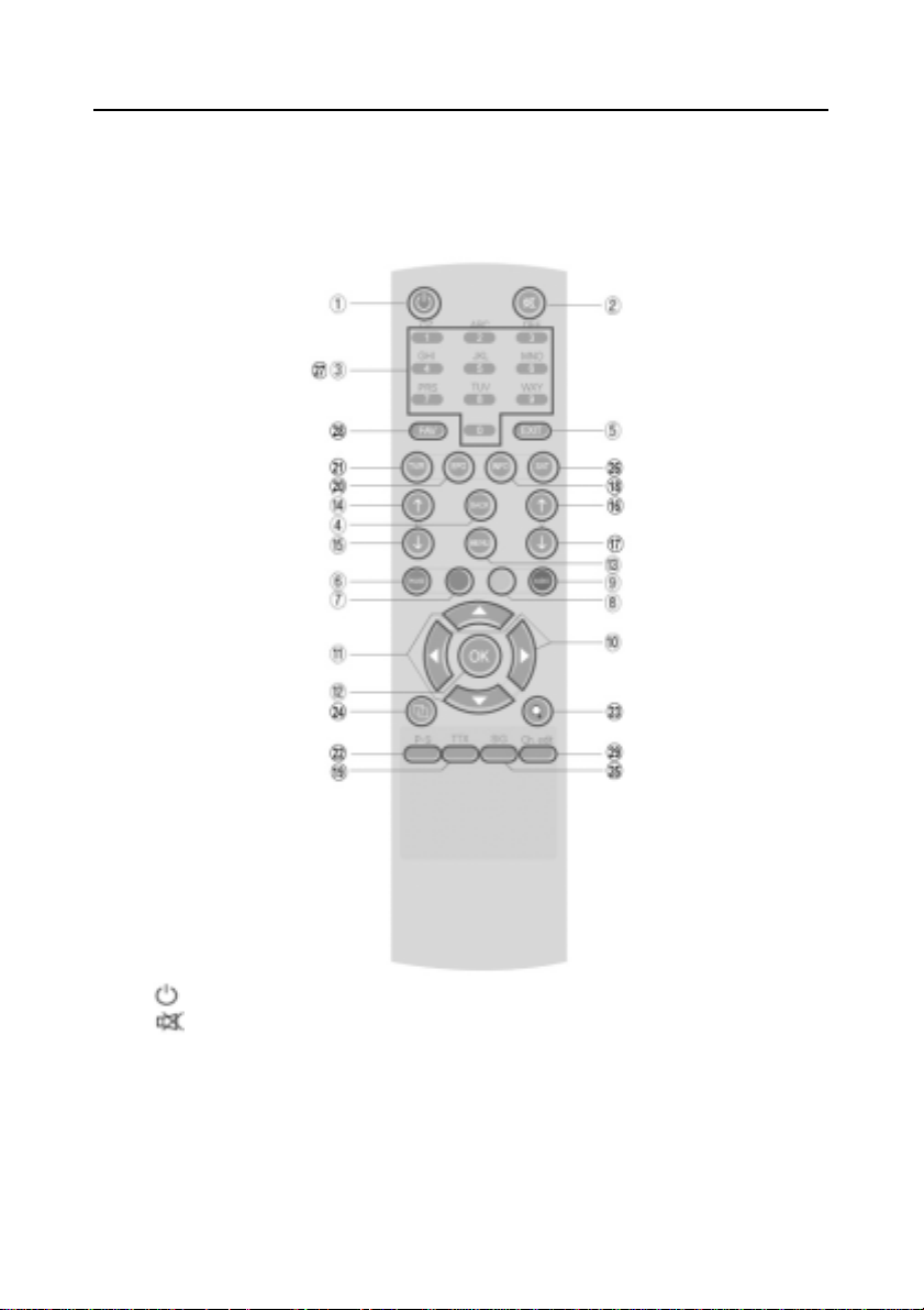
2.3. REMOTE CONTROL UNIT
1. STAND BY: Turns the receiver On/Off.
2. MUTE: Mutes audio output.
3. NUMERIC KEY (0-9): Controls the numerical operation and changes the
program channels directly.
4. BACK: This key returns you to the previous mode or menu. In TV View mode,
it returns you to the last viewed channel.
5. EXIT: Use this key to return to the viewing mode from any menu function.
9

MERCURY User’s Manual
6. PAUSE (Red key): To pause the video while viewing a program, but the
audio remains active.
7. UHF (Green key): This button is not used in NTSC models. (Varies by
region )
8. TV/SAT (Yellow key): Switch to antenna/cable bypass input signal.
9. AUDIO (Blue key): Selects audio mode (stereo, mono, language) and
alternative audio track.
NOTE: Red, Green, Yellow, and Blue Keys: These colored keys are used for
additional functions while in the Menu, or while playing video games.
10. CH UP/DOWN (▲,▼): Changes channels in Non-menu state. Moves the
curser position up/down while in the Menu state.
11. VOL UP/DOWN (◄,►): Changes the volume level in the Non-menu state.
Changes settings in the Menu state. Moves to next or previous step.
12. OK: The OK key is used to select a program, highlighted line or parameter
value. It is also used to show the TV/Radio Channel List while watching TV or
listening to the Radio.
13. MENU: Shows the Main Menu on the screen.
14. PAGE UP (P ): Used to move the highlight bar upwards one page at a
time in menus, or will scroll the INFO bar up while viewing a channel.
15. PAGE DOWN (P ): Used to move the highlight bar downwards one page
at a time in menus, or will scroll the INFO bar down while viewing a channel.
16. Volume (V ): Volume up. Controls volume in select menu screens.
17. Volume (V ): Volume down. Controls volume in select menu screens.
18. INFO: Shows the program information on the screen.
19. TTX: This key shows teletext information about the channel (if available).
20. EPG: This key shows program information about the channel (if available).
21. TV/RADIO: Selects TV or Radio mode.
22. P. S . : POWER Scan (blind search) quick start button.
23. ZOOM: Zoom function in the viewing mode.
24. MULTI CH: Multi Channel function in the viewing mode.
25. SIGNAL: Signal function in the viewing mode.
26. SAT: Selects a satellite.
27. A~Z: Use these keys in the Channel List view to find channels alphabetically.
28. FAV: Selects the favorite channels list. Can be used while viewing a TV
channel or the TV Channel List.
29. Ch. edit: Channel Edit quick start button while viewing a channel.
10
MERCURY User’s Manual
3. CONNECTION DIAGRAM
3.1. CONNECTION DIAGRAM (without a satellite dish)
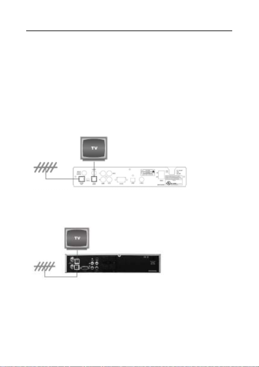
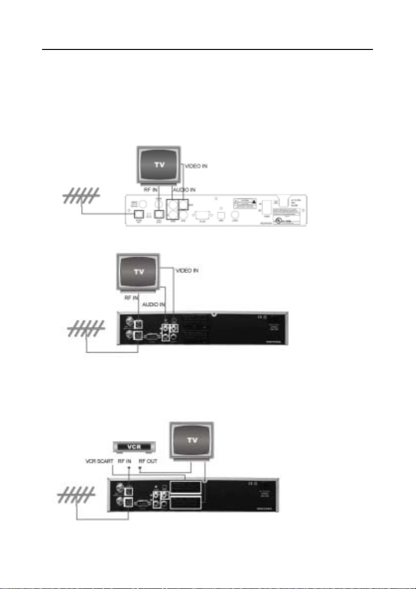
3.1.1. Receiver to TV with RF
Connect the TV antenna to the ANT IN socket on the receiver.
Connect the TV out on the receiver to the RF / Cable INPUT of the TV set.
North American model: Select VHF Channel 3 or 4 on the TV set.
Select the same channel number on the Rear Panel of the receiver.
European and Middle East models: Search on the TV set for UHF Channel 38.
Channel 38 is set at factory.
11
MERCURY User’s Manual
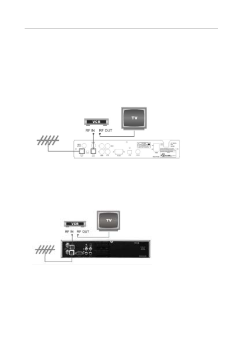
3.1.2. Receiver to VCR and then to TV with RF
Connect the TV antenna to the ANT IN socket on the receiver.
Connect the TV out on the receiver to the RF / Cable IN of the VCR.
Connect the RF output on the VCR to the RF / Cable IN on the TV set.
North American model: Select VHF channel 3 or 4 on the TV set and the VCR.
European and Middle East models: Search on the TV set and the VCR for UHF
channel 38.
Note: USE different UHF channels for VCR and receiver.
12
MERCURY User’s Manual
3.1.3. Receiver to TV with Audio/Video cables or SCART cables
Connect the TV antenna to the ANT IN socket on the receiver.
Connect the Video and Audio output on the receiver to the Video and Audio
inputs of the TV set.
North American model:
European and Middle East models:
For European and Middle East models, SCART cables can be used
Connect the SCART cable from the TV SCART of the receiver to the SCART of
the TV set. Connect the SCART cable from the VCR SCART of the receiver to
the SCART of the VCR.
13
MERCURY User’s Manual
3.2. CONNECTION DIAGRAM (with a satellite dish)
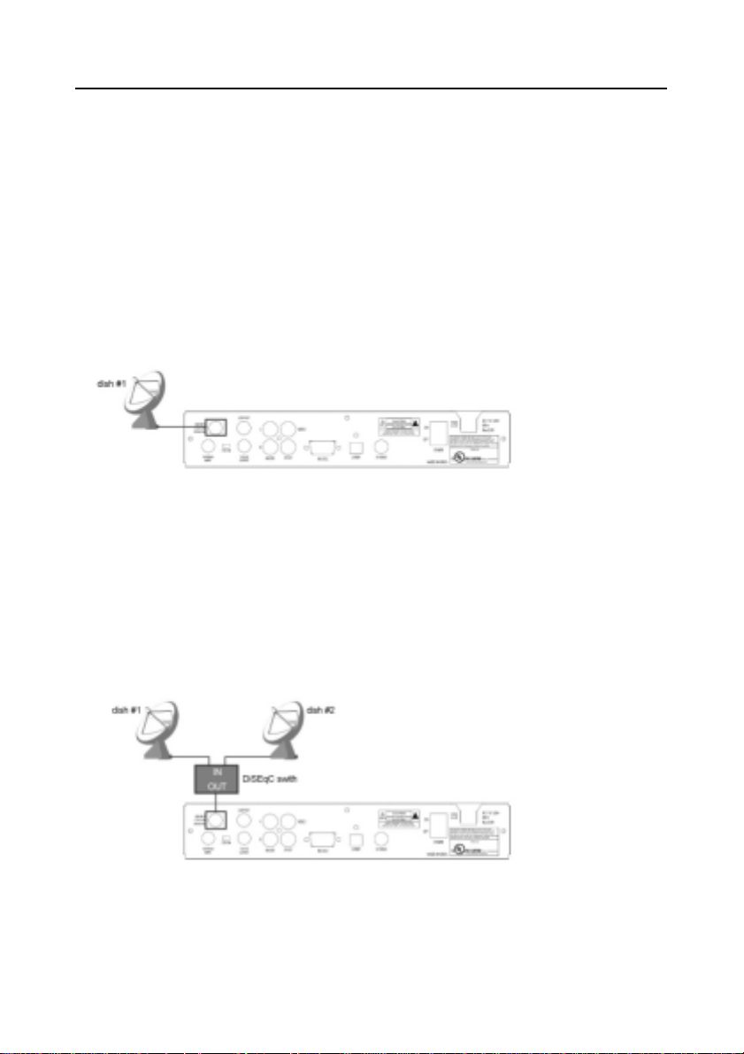
3.2.1 . One Dish
Connect the cable from the satellite dish to the LNB Input socket on the
receiver.
Connect the TV out socket on the receiver to the RF / Cable IN of the TV set.
For improved picture quality, connect the Video and Audio output on the
receiver to the Video and Audio inputs of the TV set (RCA jacks). For the best
picture quality, connect the S-Video from the receiver to your TV, or use the
SCART connections when supplies - connectors vary by region.
3.2.2. Two Dishes with a DiSEqC Switch
If you want to watch programs from more than one satellite (for example, from
Intelsat America 5 and from AMC 4) it can be done using two fixed dishes (fixed,
meaning permanently pointed at one satellite) and a DiSEqC switch. Connect
the two cables from the satellite dishes to a DiSEqC switch. From the switch,
connect a cable to the LNB Input socket on the receiver.
If you need to install a more complicated configuration of multiple dishes and
receivers, please consult with a professional satellite installer.
14
 Loading...