

Page 1
p
SERVICE MANUAL
PDP42U3H
1. Caution………………………………………………….2
2. Specification…………………………………………….6
3. BOM List………………………………………………..8
4. Alignment Procedure………………………………….18
5. Block Diagram………………………………………....22
6. Schematic Diagram……………………………………23
7. Explode View Diagram………………………………..45
This manual is the latest at the time of printing, and does not
include the modification which may be made after the
rinting, by the constant improvement of product.
Page 2
RISK
ELECTRI
SHOCK
NOT
OPEN.
SCHNEIDER ELECTRONICS GMBH-GERMANY
2
1. CAUTION
CAUTION:
Use of controls, adjustments or procedures other than those specified herein may result in
hazardous radiation exposure.
CA UT ION : TO RE DUCE THE RIS K OF
CA U T ION
RISK
OF ELE CTR I
SHOCK
The lighting flash with arrowhead symbol, with an equilateral triangle is intended to
alert the user to the presence of uninsulated voltage within the products
enclosure that may be of sufficient magnitude to constitute a risk of electric shock to
the person.
The exclamation point within an equilateral triangle is intended to alert the user to the
presence of important operating and maintenance (servicing) instructions in the
literature accompanying the appliance.
DO NOT
C
OPEN.
ELECTR ICA L SHOCK, DO NOT RE MOVE
COVER (OR BACK). NO USER SER VIC EABLE
PAR TS INS IDE . RE FER SER VIC ING TO
QUALIFIE D SERVICE PE RSONNEL.
dangerous
WARNING: TO REDUCE RISK OF FIRE OR ELECTRIC SHOCK, DO NOT
EXPOSE THIS APPLIANCE TO RAIN OR MOISTURE.
2
Page 3

SCHNEIDER ELECTRONICS GMBH-GERMANY
3
IMPORTANT SAFETY INSTRUCTIONS
CAUTION:
Read all of these instructions. Sa ve these instructions for later use . Follo w all Warnings and
Instructions marked on the audio equipment.
1. Read Instructions-All the safety and operating instructionsshouldbe read before the productis operated.
2. Retain Instructions- The safety and operating instructions should be retained for future reference.
3. Heed Warnings- All warnings on the product and in the operating instructions should be adhered to.
4. Follow Instructions- All operating and use instructions should be followed.
FOR YOUR PERSONAL SAFETY
1. When the power cord or plug is damaged or frayed, unplug this television set from the wall outlet and refer servicing to
qualified service personnel.
2. Do not overload wall outlets and extension cords as this can result in fire or electric shock.
3. Do not allow anything to rest on or roll over the power cord, and do not place the TV where power cord is subject to
traffic or abuse. This may result in a shock or fire hazard.
4. Do not attempt to service this television set yourself as opening or removing covers may expose you to dangerous
voltage or other hazards. Refer all servicing to qualified service personnel.
5. Never push objects of any kind into this television set through cabinet slots as they may touch dangerous voltage
points or short out parts that could result in a fire or electric shock. Never spill liquid of any kind on the television set.
6. If the television set has been dropped or the cabinet has been damaged, unplug this television set from the wall outlet
and refer servicing to qualified service personnel.
7. If liquid has been spilled into the television set, unplug this television set from the wall outlet and refer servicing to
qualified service personnel.
8. Do not subject your television set to impact of any kind. Be particularly careful not to damage the picture tube surface.
9. Unplug this television set from the wall outlet before cleaning. Do not use liquid cleaners or aerosol cleaners. Use a
damp cloth for cleaning.
10.1. Do not place this television set on an unstable cart, stand, or table. The television set may fall, causing serious injury
to a child or an adult, and serious damage to the appliance. Use only with a car t or stand recommended by the
manufacturer, or sold with the television set. Wall or shelf mounting should follow the manufacturer s instructions, and
should use a mounting kit approved by the manufacturer.
10.2. An appliance and cart combination should be moved with care. Quick stops, excessive force, and uneven surfaces
may cause the appliance and cart combination to overturn.
3
Page 4
SCHNEIDER ELECTRONICS GMBH-GERMANY
4
PROTECTION AND LOCATION OF YOUR SET
11. Do not use this television set near water ... for example, near a bathtub, washbowl, kitchen sink, or laundry tub, in a
wet basement, or near a swimming pool, etc.
Never expose the set to rain or wate r. If the set has been exposed to rain or water, unplug the set from the wall
outlet and refer servicing to qualified service personnel.
12. Choose a place where light (artificial or sunlight) does not shine directly on the screen.
13. Avoid dusty places, since piling up of dust inside TV chassis may cause failure of the set when high humidity persists.
14. The set has slots, or openings in the cabinet for ventilation purposes, to provide reliable operation of the receiver, to
protect it from overheating. These openings must not be blocked or covered.
Never cover the slots or openings with cloth or other material.
Never block the bottom ventilation slots of the set by placing it on a bed, sofa, rug, etc.
Never place the set near or over a radiator or heat register.
Never place the set in enclosure, unless proper ventilation is provided.
a built-in
PROTECTION AND LOCATION OF YOUR SET
15.1. If an outside antenna is connected to the television set, be sure the antenna system is grounded so as to provide some
protection against voltage surges and built up static charges, Section 810 of the National Electrical Code, NFPA No.
70-1975, provides information with respect to proper grounding of the mast and supportingstructure, grounding of the
lead-in wire to an antenna discharge unit, size of grounding conductors, location of antenna dischargeunit, connection
to grounding electrode, and requirements for the grounding electrode.
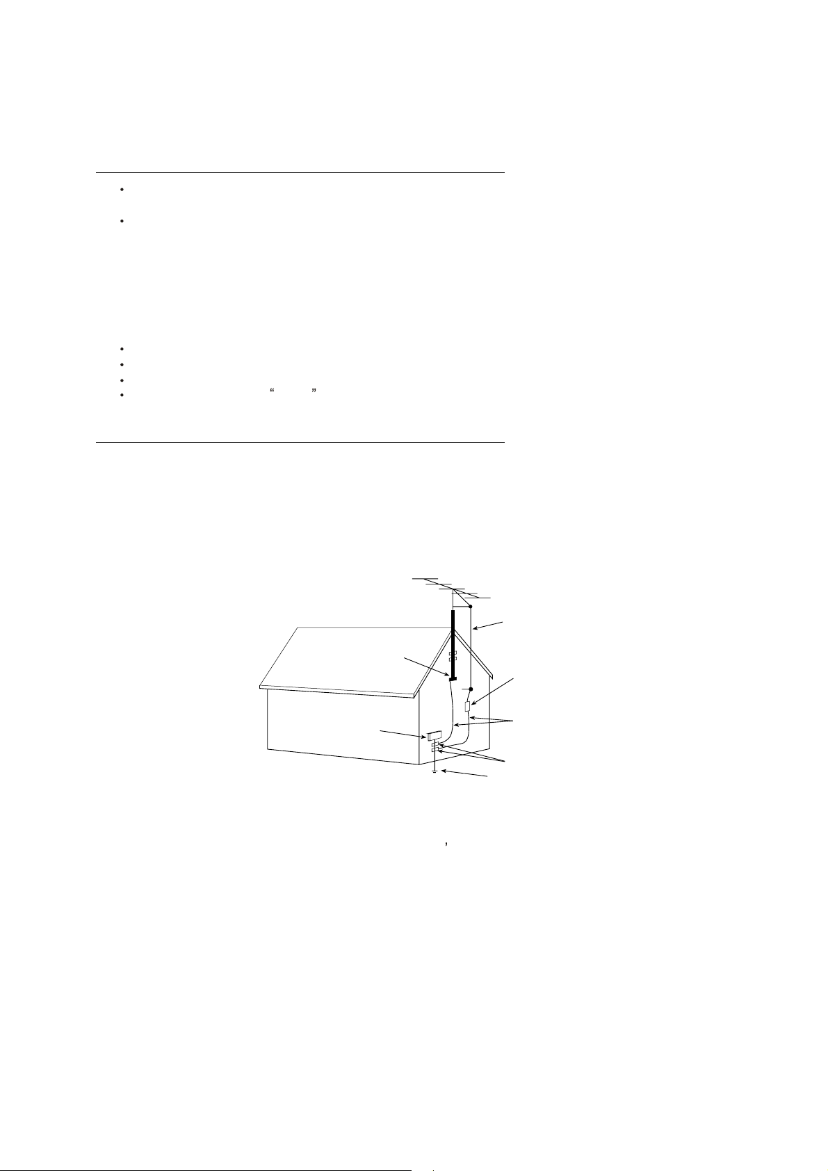
EXAMPLE OF ANTENNA GROUNDING AS PER NATIONAL ELECTRICAL CODE INSTR UCTIONS
EXAMPLE OF ANTENNA GROUNDING AS PER
NATIONAL ELECTRICAL CODE
ANTENNA
LEAD- IN WIRE
GROUND CLAMP
ELECTRIC SERVICE
EQUIPMENT
NEC-NATIONAL ELECTRICAL CODE
ANTENNA DISCHARGE
UNIT (NEC SECTION
810-20)
GROUNDING
CONDUCTORS
(NECSECTION 810-21)
GROUND CLAMPS
POWER SERVICE GROUNDING
ELECTRODE SYSTEM
(NEC ART 250. PART H)
15.2. Note to CATV system installer : (Only for the television set with CATV reception)
This reminder is provided to call the CATV system attention to Article 820-40 of the NEC that provides
installer s
guidelines for proper grounding and, in particular, specifies that the cable ground shall be connected to the grounding
system of the building, as close to the point of cable entry as practical.
16. An outside antenna system shouldnot be located in the vicinity of overhead power lines or other electric lights or power
circuits, or where it can fall into such power lines or circuits. When installing an outside antenna system, extreme care
should be taken to keep from touching such power lines or circuits as contact with them might be fatal.
17. For added protection for this television set during a lightning storm, or when it is left unattended and unused for long
periods of time, unplug it from the wall outlet and disconnect the antenna. This will prevent damage due to lightning
and power-line surges.
4
Page 5

SCHNEIDER ELECTRONICS GMBH-GERMANY
5
OPERATION OF YOUR SET
18.
This television set should be operated only from the type of power source indicated on the marking label.If you are not
sure of the type of power supply at your home, consult your television dealer or local power company. For television
sets designed to operate from battery power, refer to the operating instructions.
19. If the television set does not operate normally by following the operating instructions, unplug this television set from the
wall outlet and refer servicing to qualifiedservice personnel. Adjust only those controls that are covered in the operating
instructions as improper adjustment of other controls may result in damage and will often require extensive work by a
qualified technician to restore the television set to normal operation.
20. When going on a holiday : If your television set is to remain unused for a period of time, for instance, when you go on
a holiday, turn the television set and unplug the television set from the wall outlet.
off
IF THE SET DOES NOT OPERATE PROPERLY
21. If youare unable to restore normaloperation by followingthe detailedprocedurein youroperating instructions,
do not attempt any further adjustment. Unplug the set and call your dealer or service technician.
22. Whenever the television set is damaged or fails, or a distinct change in performance indicates a need for
service, unplug the set and have it checked by a professional service technician.
23. It is normal for some TV sets to make occasional snapping or popping sounds, particularly when being
turned on or off. If the snapping or popping is continuous or frequent, unplug the set and consult your
dealer or service technician.
FOR SERVICE AND MODIFICATION
24. Do not use attachments not recommendedby the television set manufacturer as they may cause hazards.
25. When replacementparts are required,be sure the service technicianhas used replacementparts specified
by the manufacturer that have the same characteristics as the original part. Unauthorized substitutions
may result in fire, electric shock, or other hazards.
26. Upon completion of any service or repairs to the television set, ask the ser vice technician to perform
routine safety checks to determine that the television is in safe operating condition.
5
Page 6
Environment
6
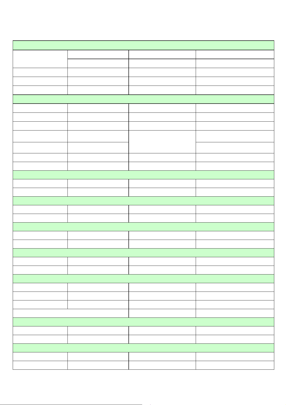
2.Product Specification
Environment Temperature
Humidity
Air Pressure(kps) 86~106
Screen Parameter
Screen Size 42“ Angle of View (H/V) 160°/160°
Max. Resolution 852 x 480 Responsive Time um
Ratio
Contrast ( Darkness,
Nakedness)
Luminance of Peak
Value(cd/m²)
Colors Supporting 16.7 M Max. V. Frequency(Hz) TV: 60Hz / PC: 85Hz
Max. H. Frequency(Hz) TV:15.7kHz / PC: 69kHz
Color System(AV)
■PAL □PAL - M ■NTSC 3,58 ■SECAM
□PAL - N ■NTSC 4,43 Comb-Filter: ■NTSC ■PAL
Operation Temperature(℃) 0~45
Store Temperature(℃)
Operation Humidity(%) 20~80%
Store Humidity(%) 20~90%
■16:9 □4:3
3000:1
1000
-10~60
Image Size(mm x mm) 1.08 × 1.08
Color Temperature(°K)
Warm:9300
Cool:11000
PC Signal
■VGA ■SVGA ■XGA □WXGA
□SXGA □True XGA
SDTV /HDTV Signal
■VGA
■Y/Pr/pb
Antenna(
■PAL DK ■PAL I ■PAL BG ■NTSC-M
■SECAM DK ■SECAM I ■SECAM BG □ SECAM L
Special Features
□100 Hz Progressive Scan ■Black and White Mode ■Smart Picture ■DLTI
■50/60 Hz Progressive Scan □Child Lock ■MADA ■DCTI
■Black Stretch ■PIP (PC 、DVI Mode)■Picture Dynamic Reduce Noise ■Timer On/Off
■Color Temperature Adjustment
Stereo
■Nicam □MTS □FM-FM ■German Stereo
□ BTSC
RF)
■720×480p ■720×576p ■1280×720p ■1920×1080i
■720×480p ■720×576p ■1280×720p ■1920×1080i
Program
□Program Auto Mark ■Program Compositor ■Channels: 99
■ Auto Searching ■Manual Searching ■Tuning
Page 7
Teletext
7
Type: Pages:
Audio
□Insert SPK. ■ Insert Amplifier ■Sound Effect ■AVC
■Output Power(W):
■Sound Effect Adjustment: ■ Bass ■Treble ■Balance ■Others:Five Bands Equalizer
Display
OSD(2 languages)
Adjustment via OSD
■Contrast ■Chroma ■H/V - size(PC)□Picture Rotation
■Brightness ■Tint ■H/V - place (PC)
Connector
Plasma Multimedia Monitor
2×8W
English,Chinese
□Antenna Input
Video Terminal
■VGA Input(Type:D-15 Pins Quantity: 1)□VGA Output(Type:Quantity:
■ DVI Input Type:DVI-I 29Pins Quantity:1)■RS-232 (Type:D-9PIN Quantity: 1)
■Y/Pb/Pr (Y/Cb/Cr) input ( ■RCA □BNC Quantity:1)
■AV Input(■RCA □BNC Quantity:1 Note: input from Y port of Y/Cb/Cr )
■S-Video Input (Quantity: 1 ) □S-Video Output(Quantity: 1 )
□SCART(□Full SCART □Video Input □ YUV Input □ S-Video □
□DVSS
□BNC ■IEC □Others:
RGB□ Video Output)
□Others Video or (AV) Output or Input:□ The port connected with MFB: 15PIN
Audio Connector
■Audio Input(■RCA 2 , 1 for CVBS; 1 for Component/PC □others) □Bass Output(Audio Jack)
■Audio OutputL/R( ■RCA □Others: 1 ) □Audio Output 5.1
□Audio Digital Coaxial(RCA)□Audio digital optical ■Speaker Output (Insert Amplifier)
Power Supply
Max. Power
Consumption(W):
Standby Power
Consumption(W):
Accessories
■Remote Controller ■VGA line (Type:DB15 )■Power Supply LIne (1.8 m) □Scart Line ( m)
□Multifunction Box ■Antenna (1.8 m) ■Speakers(Optional)■Stand(Optional)
■Bracket(
Packing
Unit Size(w×h×d, mm) 1057×662×82 Net Weight(kg) 28KG
Packing Size(w×h×d, mm) 1170×383×817 Gross Weight(kg) 35KG
Optional)
300
<3
Voltage(V/Hz):
■Switch on/off ■Auto stand-by(Timer:15 Min)
110/220VAC 50/60 Hz
Page 8

3. BOM LIST
8
ITEM DESCRIPTION LOCATION QTY.
06-0Y0938-B004X ASS'Y-REMOTE HANDSET 1
11-0BC337-0BX TRANSISTOR (NPN) BC337-40 Q1501 1
13-18L901-SCB IC MX18L901SC U1501 1
14-IRE05B-XX0 IR EMITTING DIODE TSAL6200 D1501 1
19-BB0105-JTX SMD. RES 1M OHM 1/10W +/-5% 0805 R1502 1
19-BB0472-JTX SMD. RES 4.7K OHM 1/10W +/-5% R1501;R1506;R1507 3
19-BB0229-JTX SMD. RES 2.2 OHM 1/10W +/-5% R1504 1
28-BB0101-JCX SMD CAP. 100 PF 50V C 0805 C1501;C1502 2
28-BB0220-JCX SMD.CAP 22 PF 50V C 0805 C1503;C1504 2
28-BD0105-ZFX SMD CAP 1UF 25V +80-20% C1505 1
40-DP4221-RMB P.C.B. REMOTE HANDSET BD 1
41-WJ0050-B00 WIRE BARE JUMPER 5MM J1;J21 2
41-WJ0060-B00 WIRE BARE JUMPER 6MM J2;J3;J4 3
45-COS455-KY0 CERAMIC RESONATOR 455KHZ X1501 1
45-OSC32K-7Y0 CRYSTAL 32.768KHZ X1502 1
49-HS38Y0-00X01 RUBBER PAD KEYS 1
55-HS38YB-0HA02 YREMOTEHANDSET-BOTTOMCABINET 1
55-HS38YD-0HA02 YBATT.DOOR 1
55-HS38YT-0HA YREMOTEHANDSET-FRONTCABINET 1
56-HS38YL-0HH02 LENS 1
63-F20070-AB2 S/T SCREW F 2 X 7 2
67-906670-0A009 ALUMINIUM FRONT PANEL 1
67-X90673-0E2 SPRING (+) 1
67-X90674-0E2 SPRING (-) 1
67-X90675-0E2 SPRING (+/-) 1
74-007030-60C POLYBAG (7CMX30CM) 1
71-270870-0A9 LABEL 1
08-DP4226-AMY ASS'Y-AUDIO AMPLIFIER BOARD 1
09-FM5817-STX SMD.DIODE FM5817 D601;D602;D603;D604 4
09-LL4148-ATX SMD. SWITCHING DIODE LL4148 D605;D607;D608;D609 4
10-1N5820-F0X DIODE 1N5820 D610 1
11-SA1015-YBX TRANSISTOR ST2SA1015Y (PNP) Q601 1
13-0L7809-CVS IC L7809 SGS (TO-220) U604 1
13-LM2596-12B IC LM2596S-12 P+ U603 1
13-NJW114-2MB IC JRC-NJW1142 U602 1
13-TA2024-00B IC TA2024 U601 1
19-BB0000-JTX SMD. RES 0 OHM 1/10W +/-5% R620;R650;R651;R652;R653;C657;C658;C659 8
19-BB0101-JTX SMD. RES 100 OHM 1/10W +/-5% R609;R610 2
19-BB0102-JTX SMD. RES 1K OHM 1/10W +/-5% R614;R626 2
19-BB0103-JTX SMD. RES 10K OHM 1/10W +/-5% R613;R615;R617 3
19-BB0109-JTX SMD. RES 1 OHM 1/10W +/-5% 0805 R627;R628 2
19-BB0202-JTX SMD. RES 2K OHM 1/10W +/-5% 0805 R602;R603;R605;R607 4
19-BB0203-JTX SMD. RES 20K OHM 1/10W +/-5% R612;R616 2
19-BB0222-JTX SMD. RES 2.2K OHM 1/10W +/-5% R618 1
19-BB0223-JTX SMD. RES 22K OHM 1/10W +/-5% R604;R601;R606;R608;R622;R623;R624;R625 8
19-BB0822-JTX SMD. RES 8.2K OHM 1/10W +/-5% R611 1
25-BCB100-M1X CAP. ELEC 10 UF 16V +/-20% C631 1
25-BFB229-M1X CAP. ELEC 2.2 UF 50V +/-20% C653 1
25-BDN221-M1X CAP. ELEC 220UF 25V +/-20% C637;C643;C648;C651 4
Page 9

ITEM DESCRIPTION LOCATION QTY.
9
25-BFA471-M1X CAP. ELEC 470 UF 50V +/-20% C652 1
25-HCB220-M1X CAP. ELEC 22 UF 16V +/-20% C614 1
25-HCB470-M1X CAP. ELEC 47 UF 16V +/-20% C649 1
C605;C606;C607;C608;C611;C619;C622;C623;
28-BB0104-ZFX SMD CAP. 0.1 UF 50V +80/-20% 0805
28-BB0222-KBX SMD CAP 0.0022UF 50V +/-10% C601;C602;C603;C604;C610;C620 6
28-BB0223-ZFX SMD CAP. 0.022 UF 50V F 0805 C609;C621 2
28-BB0224-ZFX SMD. CAP 0.22UF 50V +80%/-20% 0805 C638;C639;C644;C645 4
28-BB0334-ZFX SMD. CAP 0.33UF 50V +80%/-20% C618 1
28-BB0474-ZFX SMD. CAP 0.47UF 50V +80% -20% C640;C646 2
28-BD0105-ZFX SMD CAP 1UF 25V +80-20% C612;C613;C615;C616;C617;C634 6
28-XC0225-MTX TANTALUM CAP. 2.2 UF 16V +/-20% C630;C632 2
33-GLN300-NTX CHIP BEAD 30 OHM +/-25% L608;L609;L606 3
33-SLL330-MTX FILTER SLF12565T-33M2R8 L607 1
34-R100K2-10X COIL CHOKE SG9006 10UH +/-20% L602;L603;L604;L605 4
36-371620-00X NETWORK FILTER NF0801 T1 1
36-WID450-XX0 COIL WIDTH 45UH L601 1
40-DP4226-AMB2X P.C.B. AM BD 1
46-39299H-04X HS 4P 1007#26 500 EI-4Y/SCN-4Y J3 1
46-39445H-04X HS 4P 2547#24 200MM TJC3-4Y/SCN-4Y J2 1
46-CD015T-08L HS 8P 2547#24 150MM J1 1
47-SPK015-XX0 SOCKET WP4-4C J5 1
08-P42U3H-ANY ASS'Y-ANALOG BOARD 1
07-380FI5-NB3 TUNER TEDE9-289A TU1 1
09-0BA982-ATX SMD.DIODE BA982-GS08 D131 1
09-0BAV99-ATX HIGH SPEED DOUBLE DIODE BAV99 D102 1
09-55C33V-DTX SMD.DIODE BZV55-C33 D101 1
09-LL4148-ATX SMD. SWITCHING DIODE LL4148 D001;D002;D003;D004;D005;D006;D007;D008 8
09-RLZ8B2-DTX SMD. ZENER DIODE RLZ8.2B D904;D905;D906;D910 4
10-1N4001-EBX DIODE 1N4001 (RECTIFIER) D802 1
11-SC3779-DBX TRANSISTOR 2SC3779D (RF AMPL) Q121 1
12-BC846B-0BX TRANSISTOR BC846B Q111 1
12-BC847A-0BX SMD TRANSISTOR BC847A (NPN)
12-BC857A-0BX SMD TRANSISTOR BC857A (PNP) Q261;Q262 2
12-SK2158-0BX TRANSISTOR 2SK2158 Q012;Q013 2
13-0TDA91-78P IC TDA9178 IC202 1
13-00M24C-08B IC EEPROM 8K M24C08 IC003 1
13-0L7805-CVS +5V 1.5A IC L7805CV IC802 1
13-L7808C-D2B IC L7808CD2T-TR IC801 1
13-PT7825-MTB
13-MSP341-0TB IC MSP3410G(64PINS) IC204 1
13-TDA918-1TB IC SM TDA9181T/N1 (PHSE) R IC203 1
13-TDA932-1HB IC SM TDA9321H/N2 (PHSE) R IC201 1
13-V212MV-64B IC MTV212MV64I MCU (WRITE) IC001 1
18-FH0120-JLX RES. M.O. 12 OHM 3W +/-5% R801 1
19-AA0000-FTX SMD. RES 0 OHM 1/16W +/-1% 0603 R109;R140;R220;R224;R232;R238 6
19-AA0101-JTX RES. SMD 100 OHM 1/16W +/-5%
IC PTTM7825MT(5V)
C624;C625;C626;C627;C628;C629;C633;C635;
C636;C641;C642;C647;C650;C654;C655
Q131;Q202;Q203;Q204;Q205;Q206;Q263;Q271;
Q272;Q281;Q902;Q905;Q906;Q912;Q913;Q914;
Q916;Q917
IC002 1
R016;R019;R020;R021;R026;R031;R032;R106;
R107;R206;R207;R028;R212;R216;R217;R218;
R288;R284;R285;RN1;RN2
23
18
21
Page 10

ITEM DESCRIPTION LOCATION QTY.
10
R111;R112;R123;R137;R139;R225;R233;R239;
19-AA0102-JTX RES. SMD 1K OHM 1/16W +/-5%
19-AA0103-JTX RES. SMD 10K OHM 1/16W +/-5%
19-AA0473-JTX RES.SMD 47K 1/16W 0603 +/-5% R017;R014;R272 3
19-AA0104-JTX RES. SMD 100K OHM 1/16W +/-5% R110;R954;R958;R208 4
19-AA0151-JTX SMD RES. 150 OHM 1/16W +/-5% R122 1
19-AA0153-JTX RES.SMD 15K 1/16W 0603 +/-5% R209 1
19-AA0182-JTX SMD. RES 1.8K OHM 1/16W +/-5% 0603 R133 1
19-AA0222-JTX RES. SMD 2.2K OHM 1/16W +/-5% R132;RN10;RN11;RN7;RN8 5
19-AA0223-JTX RES.SMD 22K 1/16W 0603 +/-5% R135;R138;R271;R905;R926;R929 6
19-AA0224-JTX SMD. RES 220K OHM 1/16W +/-5% 0603 R963 1
19-AA0274-JTX RES.SMD 270K OHM 1/16W 5% R103 1
19-AA0301-JTX RES.SMD 300 OHM 1/16W +/-5% 0603 R245;R270 2
19-AA0330-JTX RES. SMD 33 OHM 1/16W +/-5% R124 1
19-AA0331-JTX RES. SMD 330 OHM 1/16W +/-5% R210;R211;R237;R265;R266;R268;R269 7
19-AA0332-JTX RES. SMD 3.3K OHM 1/16W +/-5% R263;R919;R922 3
19-AA0391-JTX RES.SMD 390 OHM 1/16W +/-5% 0603 R231;R261 2
19-AA0471-JTX RES. SMD 470 OHM 1/16W +/-5%
19-AA0472-JTX RES. SMD 4.7K OHM 1/16W +/-5% R029;R030;R033;R034 4
19-AA0560-JTX SMD RES. 56 OHM 1/16W +/-5% R121 1
19-AA0561-JTX RES SMD 560OHM 1/16W +/-5% R264;R267 2
19-AA0680-JTX RES. SMD 68 OHM 1/16W +/-5% R962 1
19-AA0682-JTX SMD. RES 6.8K 1/16W +/-5% 0603 R131;R920;R923 3
19-AA0820-JTX SMD. RES 82 OHM 1/16W +/-5% 0603 R904;R924;R925 3
R243;R246;R262;R273;R282;R907;R928;R931;
R960;R965;R966;R971;R972;R973;R974
R010;R011;R012;R013;R015;R027;R079;R080;
R134;R213;R214;R215;R906;R927;R930;RN13
R125;R230;R236;R275;R281;R939;R961;R964;
R967;R975
23
16
10
19-BB0000-FTX SMD. RES O OHM 1/10W +/-1%
25-BDA471-M1X CAP. ELEC 470 UF 25V +/-20% C804 1
27-MBC104-J0X CAP. M.P.E 0.1 UF 63V +/-5% C226;C228;C263 3
27-PBC472-J0X CAP. P.E 0.0047UF 63V +/-5% C227 1
27-PBC682-J0X CAP. P.E 0.0068UF 63V +/-5% C233 1
28-AB0102-KBX SMD. CAP 1000 PF 50V +/-10% B C924;C925;C928;C930 4
28-AB0103-ZFX CAP.SMD 10NF 50V +80-20% 0603
28-AB0104-ZFX CAP. SMD 0.1UF 50V +80%~-20% F
28-AB0180-JCX SMD. CAP 18 PF 50V +/-5% 0603 C229;C232 2
28-AB0201-JCX CAP.SMD 200PF 50V +/-5% 0603 C109 1
28-AB0271-JCX SMD. CAP 270 PF 50V +/-5% C C108 1
28-AB0300-JCX SMD CAP. 30 PF 50V +/-5% 0603 C016;C017 2
28-AB0331-JCX SMD. CAP 330 PF 50V +/-5% 0603 C282 1
28-AB0339-JCX SMD.CAP. 50V 3.3PF +/-5% CN31;CN32 2
28-AB0472-KBX CAP.SMD 4700PF 50V +/-10% 0603 C113;CN6;CN7;CN9;CN10 5
28-AB0560-JCX SMD CAP. 56 PF 50V +/-5% 0603 CN28 1
28-AC0105-ZFX SMD. CAP 1 UF 16VDC +80%/-20% C018 1
28-AD0474-ZFX SMD. CAP 0.47 UF 25V +80/-20% C205;C207;C213;C266;C269;C287 6
28-RC0105-MAH SMD. CAP 1 UF 16V +/-20% C234;C107 2
R0001;R0002;R0003;R0004;R0005;R0006;
R0007;R0008;R0009;R0010;R0011;R0012; R0013
C012;C013;C015;C044;C103;C106;C112;C122;
C131;C132;C133;C135;C202;C208;C214;C215;
C224;C230;C235;C236;C239;C242;C244;C265;
C285;C288;C802;C907;CN1;CN15;CN26;CN29;
CN30;CN33;C121
C021;C110;C111;C136;C212;C216;C217;C238;
C267;C281;C805;C909;C927;C933;C936;C938;
CN16;CN24;C807
13
35
19
Page 11

ITEM DESCRIPTION LOCATION QTY.
11
28-RC0106-MAH SMD. CAP 10 UF 16V +/-20%
28-RC0107-MAH SMD. CAP 100 UF 16V +/-20% C803 1
28-RC0225-MAH SMD. CAP 2.2 UF 16V +/-20% C261 1
28-RC0226-MAH SMD. CAP 22 UF 16V +/-20% C902;C908;C911;C922;C931;C932 6
28-RC0335-MAH SMD. CAP 3.3 UF 16V +/-20% CN17 1
28-RC0475-MAH SMD. CAP 4.7 UF 16V +/-20% C101 1
28-RC0476-MAH1 SMD. CAP 47 UF 16V +/-20% C014;C102;C201;C225;C240;CN14;CN2;C806 8
28-XC0225-MTX TANTALUM CAP. 2.2 UF 16V +/-20% C262 1
33-DLL220-KTX SMD. INDUCTOR 22 UH +/-10% 3225 L201;L203;L204;L205 4
33-ELL109-KTX SMD.COLL MGFI2012CIROKT L121 1
33-ELM100-KTX SMD. COIL 10UH +/-10% 0805 L105;L208;L209;L903;L904;L905;L906;L907 8
33-GLN121-NTX CHIP BEAD 120 OHM +/-25% FB1;FB2 2
33-GLN301-NTX CHIP BEAD 300 OHM +/-25% LN1;LN2;LN3 3
33-MLL101-MTX SMD. COIL 100 UH L001;L101 2
34-A100K0-1IX COIL CHOKE 10 UH +/-10% L261 1
34-R102K7-0EX COIL 1000 UH +/-10% L102;L103 2
34-R220J2-0EX COIL PL - 22 UH +/-5% L202 1
34-R220K2-1BX COIL CHOKE 22 UH +/-10% L801 1
38-350980-00X COIL I.F.T. 350980 FOR VCO T201 1
40-DP42U3-MAC4X P.C.B. BD 1
45-FIL4M5-0Y1 CERAMIC FILTER SFSH4.5MDB Z262 1
45-FIL5M5-0Y1 CER FILTER 5.5MHZ Z261 1
45-OSC12M-0Y2 CRYSTAL 12.0MHZ X010 1
45-OSC18M-4Y0 CRYSTAL 18.432M XN1 1
45-OSC3M5-8N0 CRYSTAL 3.58MHZ (CL=20PF) X204 1
45-OSC4M4-3N0 CRYSTAL 4.43MHZ (CL=20PF) X201 1
45-SAW376-0K0 SAW FILTER K3760K SAW1 1
46-CD040T-04B HS 4P 1007#24/1185#26 400MM TJC3-4Y JP2 1
46-FG010F-10001 HS 10P 2854#26 100MM PH-10Y/SAN-10Y JP3 1
46-FG040T-04G HS 4P 1185#26 400MM PH-4Y/SAN-4Y JP1 1
47-RCA111-HX0 3P RCA SOCKET AV-3.2-3W-X3 P901;P903 2
47-SVI008-XX0 S_VIDEO TERMINATOR P902 1
71-AV0000-T02 BARCODE LABEL 1
08-P42U3H-DIY ASS'Y-DIGITAL BOARD 1
09-0BAV99-ATX HIGH SPEED DOUBLE DIODE BAV99 D4;D5;D6;D7;D8;D12;D13;D14;D15 9
09-LL4148-ATX SMD. SWITCHING DIODE LL4148 D17;D18 2
09-RLZ5B6-DTX SMD DIODE RLZ5.6BTE11 D1;D2;D3;D9;D10;D11 6
12-BC847A-0BX SMD TRANSISTOR BC847A (NPN) Q7;Q18;Q001;Q002;Q003;Q19 6
12-BT3904-0BX SMD. TRANSISTOR MMBT3904LT1(NPN) Q1;Q2;Q3;Q4;Q5;Q6 6
12-SK3019-0BX SMD. TRANSISTOR 2SK3019 Q13;Q14;Q15;Q16 4
13-024LC1-6BB IC 24LC16B U29 1
13-024LC2-1AP IC 24LC21A (WRITE) U27;U16 2
13-LD1117-18B 1.8V REGULATOR IC LD1117S18TR U40 1
13-643220-T6B IC HY57V643220C(L)T-6 U13;U20;U21 3
13-89C205-12P IC AT89C2051-24PI(DIP) (WRITE) U35 1
13-BGA388-00B IC BGA388 U18 1
13-TFP401-APB IC TFP401APZP U26 1
13-63LVDM-83B IC THC63LVDM83R U44 1
13-EF4052-BTB IC HEF4052BT(D) U8 1
13-F040PC-90P IC 4M MX29F040PC-70(WRITE) U34 1
C231;C241;C243;C280;C910;C926;C934;C935;
C937;CN11;CN12;CN22;CN23;CN25
14
Page 12
ITEM DESCRIPTION LOCATION QTY.
12
13-FLI230-00B IC FLI2300-BD U12 1
13-IC1084-CMB IC AIC1084-33CM 3.3V (TO-263) U37 1
13-0L7805-CVS +5V 1.5A IC L7805CV U36 1
13-LD1117-25B 2.5V REGULATOR IC LD1117S25(SOT-223) U41 1
13-LD1117-33B IC LD1117 3.3V U39;U42 2
13-ST232C-D0B IC ST232CD(SOP) U43 1
13-PT7825-MTB
13-PT7825-STB IC PTTM7825ST( 3.3V) U19 1
13-P80C32-UBB IC P80C32UBA(PLCC44) U31 1
13-PI5V33-0QB IC PI5V330Q (QSOP) U10 1
13-RT9172-N25 IC RT9172N-25CM5 U38 1
13-SN74AH-C1B IC SN74AHC139DR U32 1
13-SN74HC-14B IC SN74HC14D-SOP14 U3 1
13-SN74HC-37B IC SN74HC373 U33 1
13-T9883B-11B IC MST9883B110 U11 1
13-TB1274-BFBG IC TB1274BFG U4 1
15-LED20R-XX0 CHIP LED HMF0805POM-BR1 D22 1
18-FH0479-JLX RES. M.O. 4.7 OHM 3W +/-5% R335 1
18-FH0689-JLX RES.M.O. 3W 6.8 OHM +/-5% R336 1
19-BB0000-JTX SMD. RES 0 OHM 1/10W +/-5%
19-BB0100-JTX RES. SMD 10 OHM 1/10W +/-5%
19-BB0101-JTX SMD. RES 100 OHM 1/10W +/-5%
19-BB0102-JTX SMD. RES 1K OHM 1/10W +/-5% R330;R5;R14;0R17;R20;R44;R3;R8;R13 9
19-BB0103-JTX SMD. RES 10K OHM 1/10W +/-5%
19-BB0104-JTX SMD. RES 100K OHM 1/10W +/-5% 0805 R226;R158 2
19-BB0121-JTX SMD. RES 120 OHM 1/10W +/-5% R2;R10;R95;R255;R256;R259;R262 7
19-BB0151-JTX RES. SMD 150 OHM 1/10W +/-5% R99;R100;R96;R97;R104 5
19-BB0220-JTX SMD. RES 22 OHM 1/10W +/-5%
19-BB0272-JTX SMD. RES 2.7K OHM 1/10W +/-5% R52;R90 2
19-BB0273-JTX SMD. RES 27K OHM 1/10W +/-5% R40 1
19-BB0330-JTX SMD. RES 33 OHM 1/10W +/-5% 0805 R7 1
19-BB0332-JTX SMD. RES 3.3K OHM 1/10W +/-5% R4;R19;R23;R34;R37 5
19-BB0391-JTX RES. SMD 390 OHM 1/10W +/-5% R195 1
19-BB0470-JTX SMD. RES 47 OHM 1/10W +/-5% R183 1
19-BB0471-JTX SMD. RES 470 OHM 1/10W +/-5% R24;R35;R39;R46;R116;R300;R009;R011;R013 9
19-BB0472-JTX SMD. RES 4.7K OHM 1/10W +/-5%
IC PTTM7825MT(5V)
U30 1
L16;R124;R125;RS1;0RS1;RS2;R12;0R12;R17;
0R19;R41;R72;R73;R74;R75;R76;R77;R78;
R79;R80;R81;R83;R85;R87;R89;R110;R111;
R112; R113;R175;R176;R188;R227;R228;R281;
R285; MR1;MR3;MR4;MR5;MR6;MR7;MR8;0R3;
R327; R328;R329;R282;R283;R284;R008;R010;
R012; R212;R117;R119;R121;R48;OR15;R123
0R4;0R5;0R6;0R8;0R9;0R21;R108;R151;R152;
R153;R154;R155;R179;R180;R181;R182;R184;
R114
R25;R26;R27;R28;R29;R45;R47;R49;R50;
R127;R128;R130;R132
R11;R38;R42;R91;R94;R98;R135;R136;R145;
R146;R147;R157;R159;R161;R165;R167;R178;
R225;R235;R242;R243;R244;R245;R246;R247;
R248;R249;R250;R251;R252;R253;R254;R257;
R258;R260;R261;R1;R18;R21;R30;R018;R325;
R326
R92;R93;R101;R102;R103;R150;R160;R162;
R163;R164;R166;R168;R169;R170;R171;R172;
R173;R174;R177;R185;R196;R287;R288;R319;
R320;R014;R331;R332;R333;R334
R6;R9;R31;R32;R187;R189;R191;R192;R193;R19
9;R201;R229;R230;R231;R232;R233;R234;R236;
R237;R238;R239;R240;R241;R131
60
18
13
43
30
24
Page 13
ITEM DESCRIPTION LOCATION QTY.
13
19-BB0473-JTX SMD. RES 47K OHM 1/10W +/-5% 0805 R105;R156;R224 3
19-BB0682-JTX SMD. RES 6.8K OHM 1/10W +/-5% R51 1
19-BB0750-JTX SMD. RES 75 OHM 1/10W +/-5% R22;R33;R36;R118;R120;R122 6
RP1;RP2;RP3;RP4;RP5;RP6;RP7;RP8;RP11;
RP12;RP13;RP15;RP17;RP25;RP26;RP27;
23-A08220-JBX NETWORK RES. 22 OHM +/-5%
27-PBC103-J0X CAP. P.E. 0.01UF 63V +/-5% C25 1
27-PBC222-J0X CAP. P.E 0.0022UF 63V +/-5% C31 1
28-BB0100-JCX SMD. CAP. 10PF 50V +/-5% C116;C118;C197 3
28-BB0101-JCX SMD CAP. 100 PF 50V C 0805
28-BB0102-KBX SMD CAP. 0.001UF 50V B 0805 C101;C196;C198;C199;C204;C205;C207;C221 8
28-BB0103-ZFX SMD CAP. 0.01 UF 50V F 0805
28-BB0104-ZFX SMD CAP. 0.1 UF 50V +80/-20% 0805
RP28;RP29;RP37;RP38;RP39;RP40;RP41;
RP42;RP24;RP007;RP008;RP009;RP010;
RP011;RP012
C6;C11;C12;C13;C187;C188;C287;C288;C289;
C290;C292
C22;C38;C41;C44;C298;C299;C300;C301;
C302;C397;C399;C011
C271;C272;C273;C274;C275;C285;C293;C294;
C295;C297;C322;C331;C333;C334;C340;C342;
C345;C347;C350;C352;C356;C358;C364;C365;
C366;C367;C003;C337;C338;C383;C384;C386;
C387; C382;C394;C398;CS1;C385;CS2;C002;
CS4; C004;C005;C006;C007;C18;C19;C21;C27;
C28; C29;C30;C32;C35;C78;C82;C84;C89;C90;
C92;C93;C94;C95;C96;C107;C108;C109;C110;
C111;C112;C113;C114;C115;C119;C123;C125;
C127;C129;C130;C131;C132;C133;C134;C135;
C136;C137;C138;C139;C140;C141;C142;C143;
C147;C148;C149;C150;C151;C152;C153;C154;
C155;C156;C157;C158;C159;C160;C161;C162;
C164;C165;C166;C167;C168;C169;C170;C171;
C172;C173;C174;C175;C193;C200;C201;C202;
C203;C209;C210;C212;C213;C215;C217;C219;
C222;C223;C224;C226;C227;C228;C229;C230;
C231;C232;C234;C235;C236;C237;C238;C239;
C240;C241;C242;C243;C244;C245;C246;C247;
C248;C249;C250;C251;C252;C253;C254;C255;
C258;C259;C260;C261;C262;C263;C264;C265;
C266;C267;C268;C269;C270;CS3
31
11
12
178
28-BB0120-JCX SMD. CAP 12 PF 50VDC +/-5% C324;C325;C328;C329 4
28-BB0180-JCX SMD. CAP 18 PF 50V +/-5% C284 1
28-BB0200-JCX SMD. CAP 20 PF 50V +/-5% C117 1
28-BB0220-JCX SMD.CAP 22 PF 50V C 0805 C281;C282;C283 3
28-BB0272-KBX SMD. CAP 2700PF 50V +/-10% C373 1
28-BB0330-JCX SMD.CAP 33 PF 50V C 0805 C121;C122 2
28-BB0331-JCX SMD. CAP 330 PF 50V C 0805 C9;C3 2
28-BB0470-JCX SMD CAP. 47 PF 50V C 0805 C34;C36;C88;C91 4
28-BB0473-ZFX SMD. CAP 0.047UF 50V +80% -20% C97;C100;C104 3
28-BB0479-JCX SMD. CAP 4.7 PF 50V +/-5% C2;C5;C8;C23;C102;C105 6
28-BB0561-JCX SMD. CAP 560PF 50V +/-5% 0805 C103 1
28-BB0822-KBX CAP.SMD 8200PF 50V +/-10 0805 C87 1
28-BB0823-ZFX CAP.SMD 0.082UF 50V 80-20 0805 C85 1
28-BD0105-ZFX SMD CAP 1UF 25V +80-20% C233;C323 2
28-CC0476-MTX TANTALUM CAP. 47 UF 16V +/-20% 6032
28-DC0107-MTX TANTALUM CAP. 100 UF 16VDC +/-20% C37;C128;C146;C326;C327;C344 6
28-RD0477-MAZ ALUMINIUM CAP. 470 UF 25V +/-20% C40;C43;C336 3
C1;C4;C7;C20;C144;C145;C330;C335;C346;
C39;C42;C339
12
Page 14

ITEM DESCRIPTION LOCATION QTY.
14
C10;C14;C15;C77;C81;C120;C124;C126;C206;
C218;C220;C225;C286;C291;C296;C332;C341;
28-XC0106-MTX TANTALUM CAP.10 UF 16V +/-20%
28-XC0225-MTX TANTALUM CAP. 2.2 UF 16V +/-20% C33 1
28-XC0226-MTX SMD. CAP 22 UF 16V +/-20% C83;C211;C214;C256;C257 5
28-XC0475-MTX TANTALUM CAP. 4.7 UF 16V +/-20% B C26;C208;C216 3
28-YC0474-MTX SMD.CAP. 0.47UF 16V +/-20% C24 1
33-ELL339-KTX SMD. COIL 3.3 UH +/-10% 0805 L1;L2;L3;L13;L15;L17;L18 7
33-ELN190-NTX CHIP BEAD 19 OHM +/-25% L26;L27;L23 3
33-ELN201-NTX CHIP BEAD 200 OHM +/-25%
33-GLN190-NTX CHIP BEAD 19 OHM +/-25% (3216) L4;L5;L6;L7;L21;L28 6
40-P4226W-DIC6X P.C.B. DIGITAL 1
45-OSC13M-5Y0 CRYSTAL 13.5MHZ (SHORT FEET) X1 1
45-OSC14M-3N0 CRYSTAL 14.318MHZ U17 1
45-OSC16M-2Y0 CRYSTAL JAS16T 16.2M Y1 1
45-OSC24M-5N0 CRYSTAL 24.576 MHZ Y3 1
45-OSC27M-0Y3 CRYSTAL 27MHZ Y2 1
46-0D018F-07B01 HS 7P 1007#26 180MM EI-7Y/SCN-7Y J2 1
46-33079W-04X PIN BASE *4 TJC3-4A J6;P3;CN002 3
46-33079W-05X PIN BASE *5 TJC3-5A J8 1
46-33079W-06X PIN BASE *6 TJC3-6A J7 1
46-33079W-08X PIN BASE *8 TJC3-8A J5 1
46-35199W-04X CONN.PH-4A 4PIN PITCH=2.0MM CN003 1
46-35199W-05X CONN.PH-5A 5PIN PITCH=2.0MM P7 1
46-35199W-10X CONN. PH-10 10PIN PITCH=2.0MM CN001 1
46-39297H-12X HS 12P 1007#26 200 SCN-12Y P8 1
46-39519W-30X 30PIN BASE DF13-30DP-1.25V JH3 1
46-39539H-30X 30PIN TO 31PIN LVDS 500MM 1
47-DVI001-KX0 DVI SOCKET KL-DIV024-04A P6 1
47-ICS003-XX0 IC JACK FOR U34 1
47-RCA109-HX0 3P RCA SOCKET AV-3.2-3W-X1(R/B/G) P2 1
47-RCA123-XX0 RCA SOCKET AV-3.2-2W-G6 J4 1
47-VGA002-XX0 VGA JACKET D-SUB-15WP P4 1
47-VGA008-KX0 VGA SOCKET KL-PC09M-02 (FEMALE) JDP1 1
48-TAC001-XX0 TACT SWITCH SW1 1
67-387190-0A0 HEAT SINK FOR U18;FOR U12 2
67-387190-1A0 HEAT SINK FOR U13;FOR U20;FOR U21 3
67-387200-1A0 HEAT SINK FOR U11 1
67-387200-3A0 HEAT SINK FOR U4 1
71-AV0000-T02 BARCODE LABEL 1
08-P42U3H-DP2 ASS'Y-DISPLAY PART2 1
35-FB0101-00X FERR BEAD 1
35-FB0133-00X FERR. BEAD ZCAT3035-1330 1
4A-OPT42P-MS1 42"OPTICS FILTER 1
54-700150-000 SP0NGE BAR 2
54-807990-0U0 SPONGE 2
C343;C348;C349;C351;C353;C354;C355;C357;
C359;C360;C361;C362;C363;C163;C396;C395;
C010;C391
FB1;FB001;FB2;FB002;FB3;FB003;FB9;FB11;
FB12;FB13;FB14;FB16;FB21;FB22;FB23;FB25;
FB26;FB28;FB29;FB31;FB32;FB33;FB34;FB35;
FB41;FB43;FB44;FB49;FB50;FB51;FB52;FB53;
FB54;FB55;FB56;FB57;FB58;FB59;FB301;FB302;
FB303;FB304
35
42
Page 15

ITEM DESCRIPTION LOCATION QTY.
15
54-703860-2U0 SP0NGE BAR 2
54-703860-9U0 SP0NGE BAR 1
54-708640-0U0 PVC INLAY 1
54-710460-0U0 SPONGE (2MMX10MMX960MM) 2
54-710470-0U0 SPONGE (2MMX10MMX555MM) 2
54-714150-0U0 SPONGE 1
54-714170-0U0 INSULATION BOARD 1
54-714370-0U0 PVC TRANSPARENT INLAY 1
54-714380-1U0 SP0NGE BAR 1
54-714490-0U0 PC SCREW POST 4
54-715620-0U0 SPONGE 960X8X4 MM FOR UP & LOW SUPPORT 2
54-715620-1U0 SPONGE 520X8X4 FOR LEFT & RIGHT SUPPORT 2
54-716070-0U0 CONDUCTIVE FABRIC 35X50 4
54-716080-0U0 CONDUCTIVE FABRIC 2
54-804100-0U0 SP0NGE BAR RBCC3802-240-A 1
54-804110-0U0 SP0NGE BAR KRCF-002-15050 1
55-705160-1CN01 FORNT PANEL 1
56-4226PK-0HA02 POWER BUTTON 1
56-4226SL-0HC01 LENS 1
56-700090-1HA01 PUSH BUTTON 1
58-4U3HMP-JKTZ1 PLATE MODEL NO. 1
58-715610-1UI01 PVC 1
63-B30060-BF3 S/T SCREW B 3.0 X 6 BF MTG LED & FRONT FRAME 1
MTG BUTTON & M.FRAME;MTG COMTROL BD
63-B30080-BT2 S/T SCREW B 3 X 8 BT
63-T40160-BF2 S/T SCREW T 4 X 16 BF
63-W30080-BT4 S/T SCREW W 3 X 8 BT MTG SUPPORTS & F.PANEL 26
64-B30080-104 M/C SCREW B 3 X 8 MTG TERMINAL & T.PLATE 2
64-B30100-104 M/C SCREW B 3 X 10 MTG SHIELD COVER & PCB BD BRACKET 3
64-Z30080-104 M/C SCREW 3.0 X 8 FOR DIGITAL BD/ ANY BD/ AMY BD 10
64-B30140-304 TRIANGLE M/C SCREW B 3 X 14 3
64-B40080-102 M/C SCREW B 4 X 8 MTG COVER & MAIN SUPPORTS 9
64-B40150-104 M/C SCREW B 4 X 15 MTG PCB BD BRACKET & MODULE 3
64-B50120-102 M/C SCREW B 5 X 12 MTG MODULE & SUPPORT 4
64-F30080-103 M/C SCERW F 3 X 8 MTG POWER & TERMINAL PLATE 2
64-S40080-104 M/C SCREW S 4 X 8 1
66-702620-0E2 SCREW POST FOR TERMINAL 2
67-715630-0B0 COPPERING 1
67-M70484-0A0 BRACKET "UP" 1
67-M70485-3A0 BRACKET "LOWER" 1
67-M70486-1A0 IRON BRACKET 2
67-M70515-2G0 MODULE LEFT BRACKET 1
67-M70515-3G0 MODULE RIGHT BRACKET 1
67-M71382-1A0 BRACKET 1
67-P70522-1A904 REAR BOARD 1
67-P70523-2A901 END SOM BOARD 1
67-S70634-0E7 SCREEN CAN 1
67-S70635-0E7 SCREEN CAN 1
& M.FRAME;MTG LED BD & M.FRAME;MTG
POWER BD & F.FRAME;MTG TERMINAL &
TERMINAL PLATE
MTG MODULE & FRONT FRAME;MTG B.COVER
& M.FRAME;MTG MODULE & FRONT
FRAME;MTG B.DISPLAY & MAIN SPEAKER
19
34
Page 16

ITEM DESCRIPTION LOCATION QTY.
16
67-S70636-0E7 SCREEN CAN 1
67-S71383-0E0 SHIELD CAN 1
67-S71384-0E7 SHIELD BOX (TOP) 1
57-10654X-00F TWIST TIE NY66 2
46-CC060F-06M01 5P UL2547#26 600MM 1
54-807980-0U0 SPONGE 2
54-808000-0U0 SPONGE 1
08-P42U3H-DP3 ASS'Y-PACKING PART+B380 1
41-UK3000-0JM EARPHONE SOCKET CHANGE RCA LINE 1
41-VK1800-9UU RF. LINE OF PIN 1800 +/-50MM 1
46-39286V-15X SIGNAL LINE 1
49-204260-BAT 7# BATT. UM4 R03P SIZE AAA 2
51-GC0180-0JG POWER CORD L=1800MM 1
58-PVC001-0UI INLAY HOLDER DOOR 2
70-271510-00A SERVICE CARD 1
70-PDP000-B01 WARRANTY CARD 1
70-PDP000-W01 SERVICE INDEX 1
71-270870-0A9 LABEL 2
71-BAR002-XX0 BAR CODE LABEL 1
71-DDHD00-X02 LABEL 1
71-DYP000-TZ1 HEAT SINK LABEL 1
71-TV0000-H03 PASS CARD 1
71-YSTZ00-111 WARNING LABEL 2
71-ZGMP00-Z11 LABEL 1
72-P42U3H-003 OPERATION MANUAL 1
74-022032-6WE POLYBAG (23CMX34CMX0.06MM) 2
74-165110-20H EPE+PO 1
75-42U3BT-CC0 POLYFOAM "BT" 1
75-42U3TP-CC0 POLYFOAM"TP" 1
76-P42U3H-1AT00 CARTON BOX 1
71-268390-0A0AF LABEL (QC) GREEN 3
08-P42U3H-IRY ASS'Y-IR RECEIVER BOARD 1
02-IRR009-XX0 IR RECEIVER MODULE AT138AT-07 IR001 1
11-SC1815-YBX TRANSISTOR 2SC1815-Y (NPN) Q001;Q002 2
14-LED03D-XX0 RED/BLUE LED BT-H603RBW-31 D001 1
18-CB0102-JNX RES. C.F. 1K OHM 1/6W +/-5% R001;R002;R003;R004 4
25-BCB470-M1X CAP. ELEC 47 UF 16V +/-20% C002 1
26-EBP103-ZFX CAP. CER 0.01UF 50V +80/-20% F C001 1
34-A100K0-1IX COIL CHOKE 10 UH +/-10% L001 1
40-P4226H-IRA0X P.C.B. IR RECEIVE BD 1
41-WJ0075-B00 WIRE BARE JUMPER 7.5MM J001;J002 2
46-CE040F-05001 HS 5P 2468#24/1185#26 400MM TJC3-5Y P002 1
08-P42U3H-KBY ASS'Y-KEYPAD BOARD 1
10-HS5V1B-DBX DIODE 500MW 5.1HSB Z001;Z002;Z003;Z004 4
18-CB0471-JNX RES. C.F. 470 OHM 1/6W +/-5% R001;R002;R003;R004 4
40-P42U3H-KEA1X P.C.B KEY BD 1
46-33079W-05X PIN BASE *5 TJC3-5A P001 1
48-TAC002-XX0 TACT SWITCH SW001;SW002;SW003;SW004 4
08-P42U3H-SWY ASS'Y-SWITCH BOARD 1
40-DP4226-SWC1X P.C.B. SWITCH BD 1
46-39210W-02X01 2PIN AMP BASE HORIZONTAL P801;P802 2
Page 17

ITEM DESCRIPTION LOCATION QTY.
17
46-39317H-02X01 HS 2P 1617#18 450MM 2
48-POW001-XX0 SWITCH POWER KDC-A11 B2 SW800 1
57-702240-0UG NYLON RIVET 2
64-B30060-103 M/C SCREW B 3 X 6 2
67-M70527-0G0 SWITCH BRACKET 1
4A-SCR42P-LG4 PDP 42" KK MODULE PDP42V69001 1
V8-PU3H00-01D01 SOFTWARE CODE FOR U16 1
V8-PU3H00-01D02 SOFTWARE CODE FOR U27 1
V8-PU3H00-01M02 SOFTWARE CODE FOR U35 1
V8-PU3H00-01M01 SOFTWARE CODE FOR IC001 1
V8-PU3H00-02F01 SOFTWARE CODE FOR U34 1
Page 18

18
4. Alignment Procedure
Flowchart of alignment procedure:
Voltage
adjustment
White
balance
Adjustment
VCO and AGC
adjustment
ALIGNMENT PROCEDURE:
D-mode:
1) Press “◀” key to reduce the volume to 0 and press “MUTE” key, then press “9”, “7”,
2) Press ▼/▲ to select item ,press ◀/▶ to change the settings.
3) Press “RECALL” key to quit.
After entering D-mode , you can adjust the settings:
“3”, “5”” continually to enter the factory mode.
Press “1” to enter Page1
Item Description Default data
STAND-BY 0:work directly; 1:Stand-by after power on 1
LOGO 0: LOGO off; 1: LOGO on 1
FACT-KEY
BKEY-LK 1: Lock the panel button. 0
TV-FREEZ 1: Image freezes when switching TV channel. 0
E2P-INIT Press “▶” key to initialize the data of E2PROM. NO
SCR-SAVE 1: Display a white pattern to clear the image remains. * 0
TIMELOCK 1: Enable the ON/OFF timer. 0
Press “2” to enter Page2: White Balance adjustment menu
Item Description Default data Default data Default data
RGB MODE AV MODE
RCUT-9K3 Red cutoff at 9300k 225 249 208
GCUT-9K3 Green cutoff at 9300k 205 247 239
BCUT-9K3 BLUE cut off at 9300K 200 245 240
RGAIN-93 RED drive at 9300K 15 95 95
GGAIN-93 Green drive at 9300K 15 91 95
BGAIN-93 Blue drive at 9300K 15 100 100
RCUT-11K Red cutoff at 11000k 224 249 209
GCUT-11K Green cutoff at 11000k 220 247 237
BCUT-11K Blue cutoff at 11000k 245 100 245
RGAIN-11 RED drive at 11000K 13 86 88
GGAIN-11 Green drive at 11000K 14 88 90
BGAIN-11 Blue drive at 11000K 15 100 100
0: Enter D-mode as above;
1: Enter D-mode directly by pressing RECALL button.
* 0
YPbPr
MODE
Page 19

19
Press “3” to enter Page3: TV adjustment menu Press “4” to enter Page4: Geometry
picture geometry adjustment menu
Item DATA Item Default data
BLK-STRC 30 HB00-PAL 13
NOLINER 0 VB00-PAL 77
VGAMMA 32 HB00-NTS 29
LINE 10 VB00-NTS 75
STEEP 63 HPNL-PAL 5
CORING 10 VPNL-PAL 77
COLDELAY 7 HPNL-NTS 21
YDELAY 15
VPNL-NTS 73
AGC 4
FFA 1
FOB 1
VCO 63
LOCK OK
FREQ 471.25
I. Voltage adjustment at V
and Vs: (the required values are labeled on the top right corner
a
of the panel)
1. Coarse adjustment
1) Unplug the output of the power panel, Apply 220VAC to mains power input.
2) Adjust V
3) Adjust V
2. Fine adjustment
Adj until voltage at Va reaches the required value(±1V).
a
Adj until voltage at Vs reaches the required value(±1V).
s
1) Apply a white signal.
2) Press “M“ button to select picture menu, press ▼/▲ to select CONTRAST and
BRIGHTNESS, press ◀/▶ to change the settings to 100.
3) The set warms up about 15 min, then adjust V
Adjust V
Adjust V
Adj until voltage at Va reaches the required value (±0.5V).
a
Adj until voltage at Vs reaches the required value (±0.5V).
s
and Vs respectively.
a
II. Adjustment of White balance
i. Adjustment of White balance under RGB mode
1. Receive the 16 Gray-scale pattern,
2. Press “PICTURE” key to select STANDARD mode.
3. Adjustment of Warm temperature( 9300K)
1) Set BCUT-9K3 to 200, BGAIN-93 to 15. Use a color analyzer to measure the black
side of the screen (the scale where the luminance is about 5±1nit). Set the reading of
the color analyzer to x=0.284±0.005, y=0.299±0.005 by adjusting the value of RCUT9K3 and GCUT-9K3 repeatedly.
2) Then measure the white side of the screen (the scale where the luminance is
100±5nit). By changing the value of GGAIN-93 and RGAIN-93, set the reading of the
color analyzer to x=0.284±0.005, y=0.299±0.005.
3) Repeat step 1) & 2) until you can get the correct reading for both black and white
sides.
4. Adjustment of Cool temperature (11000K)
1) Set BCUT-11K to 200, BGAIN-11 to15. Use a color analyzer to measure the black side
of the screen (where the luminance is 5±1nit). By changing the value of RCUT-11K
Page 20

and GCUT-11K, set the reading of the color analyzer to x=0.265±0.005,
20
y=0.280±.0.005.
2) Then measure the white side of the screen where the luminance is 100±5nit. By
changing the value of GGAIN-11 and RGAIN-11, set the reading of the color analyzer
to x=0.265±0.005, y=0.280±.0.005.
3) Repeat step 1) & 2) until you can get the correct reading for both black and white
sides.
4) Press RECALL button to quit.
ii. Adjustment of White balance under AV mode
1. Receive the black/white pattern.
2. Press “PICTURE” key to select STANDARD mode.
3. Adjustment of Warm temperature( 9300K)
1) Set BCUT-9K3 to 240, BGAIN-93 to 100. Use a color analyzer to measure the black
side of the screen (the scale where the luminance is about 5±1nit). Change the value
of RCUT-9K3 and GCUT-9K3 until the reading of the color analyzer to
x=0.284±0.005, y=0.299±0.005.
2) Then measure the white side of the screen (the scale where the luminance is
100±5nit). By changing the value of GGAIN-93 and BGAIN-93, set the reading of the
color analyzer to x=0.284±0.005, y=0.299±0.005.
3) Repeat 1) & 2) until you can get the correct reading for both black and white sides.
4. Adjustment of Cool temperature(11000K)
1) Set BCUT-11K to 245, BGAIN-11 to 100. Use a color analyzer to measure the black
side of the screen (the scale where the luminance is about 5±1nit). By changing the
value of RCUT-11K and GCUT-11K, set the reading of the color analyzer to
x=0.265±0.005, y=0.280±.0.005.
2) Then measure the white side of the screen (the scale where the luminance is
100±5nit). By changing the value of GGAIN-11 and RGAIN-11, set the reading of the
color analyzer to x=0.265±0.005, y=0.280±.0.005.
3) Repeat 1) & 2) until you can get the correct reading for both black and white sides.
4) Press RECALL button to quit.
iii. Adjustment of White balance under YPbPr mode
1. Apply the 10 Gray-scale pattern to YPbPr.
2. Press “PICTURE” key to select STANDARD mode.
3. Adjustment of Warm temperature (9300K)
1) Set BCUT-9K3 to 240, BGAIN-93 to 100. Use a color analyzer to measure the black
side of the screen(the scale where the luminance is About 5±1nit ). Change the value of
RCUT-9K3 and GCUT-9K3 until the reading of the color analyzer to x=0.284±0.005,
y=0.299±0.005.
2) Then measure the white side of the screen. By changing the value of GGAIN-93 and
BGAIN-93, set the reading of the color analyzer to x=0.284±0.005, y=0.299±0.005.
3) Repeat 1) & 2) until you can get the correct reading for both black and white sides.
4. Adjustment of Cool temperature (11000K)
1) Set BCUT-11K to 245, BGAIN-11K to 100. Use a color analyzer to measure the black
side of the screen. By changing the value of RCUT-11K and GCUT-11K, set the reading of
the color analyzer to x=0.265±0.005, y=0.280±.0.005.
2) Then measure the white side of the screen. By changing the value of GGAIN-11 and
RGAIN-11, set the reading of the color analyzer to x=0.265±0.005, y=0.280±.0.005.
3) Repeat 1) & 2) until you can get the correct reading for both black and white sides.
4) Press RECALL button to quit.
Page 21

21
III. ALIGNMENT PROCEDURE FOR BOX:
1. VCO Adjustment:
1) Apply the Color-Bar signal (80dB) to TV jack.
2) Repeatedly press “M” key to AUTO SEARCH menu. Press ▼/▲ to select MANUAL
item to search the signal. After catching the program, select FINE item and adjust until the
frequency displayed in OSD is identical with the input signal.
3) Enter D-mode, then press “3” key to enter Page3.
Select LOCK item, and press “▶” key to make VCO become 63, then adjust T201 on
the Analog Board to make the image normal and LOCK become 1.
Then select VCO item, and adjust VCO very finely: First press “◀” key to make LOCK
become 0, then press “▶” key to make LOCK become OK exactly.
4) To check the searched frequency: Search the input signal in MANUAL mode and
compare the frequency displayed in OSD with the input frequency. If the error is within
0.05MHz, then the adjustment is OK.
2. AGC Adjustment:
1) Under TV mode, input Philips Test signal (Freq: 471.25MHz, Amp:60dB).
2) Enter D-mode and Page3. Then select AGC item, and adjust the value until the noise
on the background of the image just disappears. And make sure there is no AdjacentChannel Interference in the image.
3) After adjustment is OK, press RECALL button to quit the factory mode.
Page 22

5
22
FRONT PANEL CONTROL BOARD
D D
(D-SUB9)
analog
board
interface
(RCA*3)
TXD
RXD
INT_STB
SCL_STB
SDA_STB
Y_STB
Cb_STB
Cr_STB
HS_STB
VS_STB
Y/Yd_panel/CVBS
Cb/Pb_panel
Cr/Pr_panel
RX0RX0+
RX1RX1+
RX2RX2+
RXCRXC+
ANALOG R1
ANALOGG1
ANALOG B1
HSYNC1
VSYNC1
PDP42U3 don't use it.
PDP4226H should be
use it.
TC90A69
<Value>
TB1274AF
Y2
U2
V2
Y1
U1
V1
CVBS1
<Value>
TC90A69
FSC
FSC
TB1274AF
EL8300_1
G
B
R
<Value>
C_COM
Y_COM
Y_COM
C_COM
G
B
R
SCL
SDA
SCL
SDA
YS1
HS
VS
Y
U
V
EL8300
4052
<Value>
HS3
VS3
HS1
VS1
HS0
VS0
SERIAL PORT
C C
SDTV/HDTV
INPUT
B B
DVI INPUT
(DVI-25)
VGA INPUT
(D-SUB15)
CTL_X
HS_OUT
VS_OUT
4052
CTL_Y
4
89C2051
AC_ON
KEY1
RLY_ON
KEY2
5V_MONI
KEY3
VsVa_ON
KEY4
89C2051
RF
LED_R
LED_B
standby_sync
FRONT_IR
<Value>
PI5V330
PI5V330_1
Y1
SEL_Hd
U1
V1
Y2/G
U2/B
V2/R
<Value>
HS2
VS2
PI5V330_2
PI5V330
Y
Pb
Pr
G
B
R
<Value>
OR1 R
OR2 R
OR3 R
SEL_VGA
Y
U
V
AD9888
Yin1
Y
Uin1
U
Vin1
V
HSYNC1
VSYNC2
<Value>
80C32_MCU
standby_sync
FRONT_IR
TXD
RXD
INT_STB
SCL2
SDA2
JTEST
SEL_A/B
SCL1
SDA1
<Value>
SCL
AD9883A
80C32
SDA
SOGOUT
Cb[0..7]
Cr[0..7]
Y[0..7]
PCLK
3
MCA9
MCA8
MCALE
TMDSPD
JTEST
JWR
P0[0..7]
OE_DIG
VS
HS
RES
<Value>
power on reset
2
1
POWER BOARD
JRD
INT1
A18(FOR 512KB)
A18
<Value>
FLI2310
<Value>
Cb[0..7]
Cr[0..7]
PCLK
SDA
SCL
VS1
HS1
VS2
HS2
Y[0..7]
RESET
SDRAM1
ADR[0..10]
<Value>
ADR[0..10]
SiI161 (SiI169 FOR HDCP)
<Value>
DATA[0..31]
DATA[0..31]
FLI2310
SCDT
RX0RX0+
RX1RX1+
RX2RX2+
RXCRXC+
CAS#
SDWE#
CAS#
SDWE#
SiI161
RAS#
RAS#
Cb/Cr_out[0..7]
PAR[0..7]
PAG[0..7]
PAB[0..7]
HSYNC_DVI
VSYNC_DVI
DVICK
DDE
SDCLK
13.5MHZ
MEMCLKO
Y_out[0..7]
HS_DI
OSC_13.5MHZ
CLK
<Value>
JAGAUM
TEST
INTR#
MCRD#
MCWR#
MCA[0..7]
Y_PC[0..7]
C_PC[0..7]
VS_DI
PCLK
HSREF_PC
VSREF_PC
prep.
PCLK_PC
PBR[0..7]
PBG[0..7]
PBB[0..7]
RESET
GPIO4
PAR[0..7]
PAG[0..7]
PAB[0..7]
DVICLK_PA
DE_PA
HSYNC_PA
VSYNC_PA
R1_ANALOG
G1_ANALOG
B1_ANALOG
HS_PB
VS_PB
ADR[0..10]
<Value>
DATA[0..31]
TMDSPD
JAGASM
CAS#
SDWE#
OS C _ 1 4 . 3 1 8MHZ
CLK
<Value>
MCA8
MCA9
MCALE
14.318M
THC63LVDS83
THC63LVDS83
<Value>
PD[24..47]
PVSYNC
PHSYNC
PDE
PSHFCLK
SII164
PD[0..23]
PVSYNC
PHSYNC
PDE
PSHFCLK
<Value>
SiI164
PD[24..47]
PENVDD
PD[0..23]
PVSYNC
PHSYNC
PDE
PSHFCLK
GPIO0
GPIO1
GPIO3
RAS#
CLK_SDRAM
PDP42V6_PANEL
TX0-
TX0-
TX0+
TX1+
TX2+
TX3+
TX0+
TX1-
TX1-
TX1+
TX2-
TX2TX2+
TX3-
TX3TX3+
PENVDD
SCLK
SLE
SDATA
<Value>
PDP42V5_PANEL
TX0-
TX0-
TX0+
TX0+
TX1-
TX1-
TX1+
TX1+
TX2-
TX2-
TX2+
TX2+
TX3-
TX3-
TX3+
TX3+
SCLK
SLE
SDATA
<Value>
A A
PDP42U3 DIGITAL BOARD SCHEMATIC(JAGASM+FLI2300)
5
4
3
SDRAM2
ADR[0..10]
<Value>
2
CAS#
DATA[0..31]
SDRAM3
RAS#
SDWE#
CLK
<Value>
ADR[0..10]
CAS#
DATA[0..31]
CLK
SDWE#
RAS#
Title
PDP42U3H/26H DIGITAL BOARD(FLI2300+JAGASM)
Size Document Number R e v
Custom
TCL MULTIMEDIA R&D. -- YangHong
Date: She et
1
1.0
11Friday, February 20, 2004
of
Page 23

23
Page 24

5
24
4
3
2
1
CN003
1
2
3
4
J3
1
2
3
D D
C C
B B
4
5
6
7
8
9
CON9
HEAD PHONE
J4
1
2
3
4
CON4
AUDIO R/L ACR
R257
10K
AGND4
R260
10K
AGND4
C360 10UF/16V R255
C361 10UF/16V
R258
10K
C362
10UF/16V
C363
R261
10UF/16V
10K
PHONE_L_IN
PHONE_R_IN
Audio_L_IN
Audio_R_IN
AGND4
+
+
+
+
J5
1
2
3
4
5
6
7
8
CON8
R259
R262
120
PHONE_L_IN
120
PHONE_R_IN
R256
120
Audio_L_IN
120
Audio_R_IN
AGND4
CON4
+5V_STB
R340
NC
ࡴ㒭ᑣ㑻ᵓկ⬉㛮 㛮
R321 22
R322 22
TXD
RXD
RXD_MCU4
TXD_MCU4
RXD_MCU
TXD_MCU
R319 22
R320 22
R288 22
R287 22
6FKHPHIRUGLJLWDOERDUGRIGLVSOD\SDJHV
JDP1
1
1
6
6
7
7
8
8
9
9
CONN DSUB 9-P
STB CONTROL CONNECT
+5V_STB
GND
RXD
2
2
TXD
3
3
R341
4
4
NC
5
5
GND
EA# 4
EA
FB59
12
C364
GND
GND
0.1uF
0.1uF
C365 0.1uF
C366 0.1uF
C367
U43
16
15
14
13
12
11
10
VCC
GND
T1out
R1in
R1out
T1in
T2in
T2out
MAX232
1
C1+
2
V+
3
C1-
4
C2+
5
C2-
6
V-
7
89
R2inR2out
Audio Amplifier
ࡳᬒᵓᦦᑻ
J6
1
2
3
MUTE
4
CON4
GND
TO audio amplier board
A A
5
SCL_5V 4,17,18
SDA_5V 4,17,18
MUTE 3
4
Title
AUDIO CONNECTOR
Size Document Number Rev
PDP42U3H
3
2
Date: Sheet
121Monday, June 14, 2004
1
1
of
Page 25

5
25
VOLTAGE
D D
P8
+5V
+5V
+5V
GND
GND
GND
+12V
+12V
GND
GND
NC
NC
JST-S12B-PH-K
1
2
3
4
5
6
7
8
9
10
11
12
GND
GND_2596
+5V_MAIN
C332
10uF/16V
+12V_MAIN
+5V_MAIN
4
+3.3V DIGITAL POWER
LM1084CM-3.3U37
3 2
IN OUT
C333
0.1uF
GND
R281 0
4
TAB
GND
1
+5V
C334
0.1uF
C335
47uF/10V
+3.3V
3
CN002
4 HEADER
+12V_MAIN
+9V
1
2
3
4
R335 10
R337
CHANGE
GND
R338
NC
R212 R
R215 R
R336 4.7
R339
NC
NC
+12V
+5V_ANALOG
C336
470uF/25V
2
+5V ANALOG POWER
U36
1
Vin
C337
0.1uF
GND
Vout
GND
2
7805
1
C338
0.1uF
+5V_Analog
L28
3
100uH
C339
47uF/16V
+2.5V DIGITAL POWER
C C
CN4
1
2
CON
CHANGE
+9V
GND
+5V_MAIN
FB49
1 2
FB51
1 2
C344
100uF/16V
C345
0.1uF
U38 RT9172-2.5
2
Vin
1
FEEDBACK
/SD
GND
3
GND
Vout
C346
47uF/16V
C347
0.1uF
+2.5V
+5V_ANALOG
FB50
1 2
C343
10uF/16V
+3.3V ANALOG POWER
12
C340
0.1uF
LM1117MPX-3.3U39
3 2
IN OUT
TAB
GND
1
+3.3V_ANALOG
12
4
C341
10uF/16V
C342
0.1uF
4
FB52
5
1 2
JA2.5V1
FB53
B B
A A
5
FB56
1 2
C353
10uF/16V
+5V_STB +3.3V_STB
FB58
1 2
10uF/16V
GND
C359
LM1117MPX-2.5
U41
3 2
IN OUT
12
TAB
GND
1
GND
3 2
C356
0.1uF
4
10uF/16V
IN OUT
GND
1
GND
4
A2.5V
C354
LM1117MPX-3.3U42
TAB
1 2
A2.5V
FB57
1 2
12
4
C357
10uF/16V
JA2.5V2
C348
10uF/16V
AGND2
C355
10uF/16V
AGND3
C358
0.1uF
+1.8V DIGITAL POWER
+3.3V
3
FB54
1 2
FB55
1 2
12
C349
10uF/16V
2
GND
LM1117MPX-1.8U40
3 2
IN OUT
TAB
C350
0.1uF
GND
1
GND
Title
POWER
Size Document Number Rev
PDP42U3H
Date: Sheet
12
4
C351
10uF/16V
+1.8V
C352
0.1uF
1
1
of
221Monday, June 14, 2004
Page 26

5
26
4
3
2
1
GND
RF
J8
1
2
3
4
5
CON5
J7
1
2
3
4
5
6
CON6
AC_ON_PANEL
5V_MONI_PANEL
RL_ON_PANEL
VsVa_ON_PANEL
standby_sync 4
MUTE 1
LED_BLUE
ᣝ䬂ᵓᦦᑻ
R253
R252
10K
10K
LED_RED
+5V_STB
RF
KEY3
KEY2
KEY1
KEY0
D D
AC_ON_PANEL
RL_ON_PANEL
J2
1
2
3
4
5
6
7
CON7
C C
ᕙᴎ⬉⑤ᦦᑻ
R018 10K
GND
12pF
C328
C327
100uF/25V
VsVa_ON_PANEL
5V_MONI_PANEL
CONNECT WITH POWER BOARD
FRONT_IR4
24MHZ
Y3
1 2
GND
12pF
C329
RESET4
+5V_STB
AC_ON_PANEL
RL_ON_PANEL
L26 100uH
L27 100uH
VsVa_ON_PANEL
5V_MONI_PANEL
+5V_STB
R242
R243
10K
10K
KEY0
KEY1
RF
KEY2
KEY3 VsVa_ON_PANEL
FRONT_IR
R254 10K
FB44
1 2
C330
47uF/16V
R244
10K
R245
10K
C331
0.1uF
+5V_STB
C326
100uF/25V
GND
U35
2
3
6
7
8
9
11
5
4
1
20
P3.0/RXD
P3.1/TXD
P3.2/INTO
P3.3/INT1
P3.4/T0
P3.5/T1
P3.7
XTAL1
XTAL2
RST/VPP
VCC
AT89C2051/DIP20
P1.0/AIN0
P1.1/AIN1
P1.2
P1.3
P1.4
P1.5
P1.6
P1.7
12
13
14
15
16
17
18
19
LED_RED
LED_BLUE
AC_ON_PANEL
5V_MONI_PANEL
RL_ON_PANEL
standby_sync
MUTE
CONNECT WITH FRONT PANEL BOARD
+5V_STB
R250
R248
R249
R246
R247
10K
10K
make two mcu sync
R251
10K
10K
10K
10K
B B
A A
5
GND
Title
SLAVE MCU 89C2051
Size Document Number Rev
PDP42U3H
4
3
2
Date: Sheet
321Monday, June 14, 2004
1
1
of
Page 27

27
5
+5V_STB
VCC
RST
INTR_STB#
VCC_MCU
3
GND
5
3
1
RXD_MCU
TXD_MCU
SW1
OE_DIG/MCA18
standby_sync
EA#
RESET
SCL_STB19
SDA_STB19
R344
3k3
VCC_MCU
GND
MC_SCLK
MC_DATA
SCL_STB
C322
0.1UF
R226
100K
GND
OR16
OPEN
OR17
1K
MOR12 0R
GND
VCC_MCU
R238
4.7K
12
C370
NC
FLASHWE#
NC
11
13
14
15
16
17
2
3
4
5
6
7
8
9
35
10
MOR11 0R
VCC_MCU
12
GND
RST#
RST
2543
1
PBRST#
VCC
D D
DEBUG PORT
P7
+5V_STB
1
+5V
2
RXD
3
TXD
4
RESET#
5
GND
GND GND
JST-S5B-PH-K
RXD_MCU1
TXD_MCU1
FRONT_IR3
INTR_STB#19
JTEST16,18
SEL_A/B16
MC_SCLK14
MC_DATA14
OE_DIG/MCA1814
standby_sync3
C C
80C251(10.29)
80C251(10.29)
80C251(10.29)
B B
SCL_3V10,14,15
SDA_3V10,14,15
A A
EA#1
R224
D19
1N4148
47K
12
C323
SW1
1UF
PB
GND
EA#
VCC_MCU
R229
4.7K
EA#
MCWR#
MCA16
MCA17
SDA_STB
SDA_STB
MCA17
+3.3V
R231
R230
4.7K
4.7K
1
G
SD
2
Q13 2SK3019
+3.3V
R240
4.7K
1
G
SD
2
Q15 2SK3019
R342
1k
5
MOR6 4.7K
1
RESET
U30
4
PBRST-
2
GND
RST-
MAX825-D
FRONT_IR
R227 0
R228 0
MR1 0R
MOR7 0R
MR3 0R
MOR8 0R
MR4 0R
MOR9 0R
VCC_MCU
VCC_MCU
R237
R236
4.7K
4.7K
MC_SCLK
3
12
C368
NC
GND GND
MC_DATA
3
12
C369
NC
GND GND
VCC_MCU
R343
4.7k
3
Q21
D23
BC847AL
BAV70
2
GND
2 1
C324
12pF
U31
P3.0/RXD
P3.1/TXD
P3.2/INT0#
P3.3/INT1#
P3.4/T0
P3.5/T1
P1.0
P1.1
P1.2
P1.3
P1.4
P1.5
P1.6
P1.7
EA/VP
RESET
R239
4.7K
C371
NC
4
GND
1 2
Y2
27M
21
44
X1
VCC
VCC=44
GND=22
80C32
80C32PLCC
GND
VSS2
22123
MOR13 0R
R232
4.7K
1
G
SD
3
Q142SK3019
+5V
1
G
SD
3
2SK3019
Q16
4
+5V_STB
2
R241
4.7K
2
C325
12pF
20
VSS1
R225
10K
X2
RD#/P3.7
WR#/P3.6
A8/P2.0
A9/P2.1
A10/P2.2
A11/P2.3
A12/P2.4
A13/P2.5
A14/P2.6
A15/P2.7
AD0/P0.0
AD1/P0.1
AD2/P0.2
AD3/P0.3
AD4/P0.4
AD5/P0.5
AD6/P0.6
AD7/P0.7
R233
4.7K
RESET
VCC_MCU
C004
0.1uF
19
MCWR#
18
33
ALE/P
32
PSEN
MCA8
24
MCA9
25
MCA10
26
MCA11
27
MCA12
28
MCA13
29
MCA14
30
MCA15
31
MCAD0
43
MCAD1
42
MCAD2
41
MCAD3
40
MCAD4
39
MCAD5
38
MCAD6
37
MCAD7
36
VSS2
80C32-PLCC44
34
+5V
R234
4.7K
SCL_5V 1,17,18
SDA_5V 1,17,18
80C32(10.29)
C006
0.1uF
RESET 3
FB40
1 2
1 2
FB41
MOR10 0R
MR5 0R
VCC_STB
GND
MCA14
MCA15
MCRD#
MCA14
MCA15
MCWR#
CONFIGURATION
DATA
1
2
3
4 5
GND
+3.3V_STB
+5V_STB
MCA16
MCRD#
MCA17
13
14
15
17
18
19
20
21
512k OR47
U33
3
D0
4
D1
7
D2
8
D3
13
D4
14
D5
17
D6
18
D7
SN74LV373A
DQ0
DQ1
DQ2
DQ3
DQ4
DQ5
DQ6
DQ7
29EE010-DIP32
MCAD0
MCAD1
MCAD2
MCAD3
MCAD4
MCAD5
MCAD6
MCAD7
MCALE
MCAD0
MCAD1
MCAD2
MCAD3
MCAD4
MCAD5
MCAD6
MCAD7
SOCKET-DIP32
OR19 0R
OR20 0R
㽕㑻 䳔 ˈ㢹᮴߭
BIOS
JRD#
JWR#
FB42
1 2
+5V_STB
1 2
+3.3V_STB
FB43
168
U32A
2
Y0
A
3
VCCGND
Y1
B
Y2
1
Y3
G
168
U32B
14
A
Y0
13
VCCGND
B
Y1
Y2
15
G
Y3
3
U29
A0
VCC
A1
TEST
A2
SCL
SEEPROM
GND SDA
AT24C16
80C251(10.29)
MCA[15..0]
VCC_MCU
C005
0.1uF
2010
GND
MCA0
2
Q0
MCA1
5
VCCGND
Q1
MCA2
6
Q2
MCA3
9
Q3
MCA4
12
Q4
MCA5
15
Q5
MCA6
16
Q6
MCA7
19
Q7
111
OCG
GND
VCC_MCU
C007
0.1uF
GND
U34
MCA0
12
A17
A0
MCA1
11
A1
MCA2
10
A2
MCA3
9
A3
MCA4
8
A4
MCA5
7
A5
MCA6
6
A6
MCA7
5
A7
MCA8
27
A8
MCA9
26
A9
MCA10
23
A10
MCA11
25
A11
MCA12
4
A12
MCA13
28
A13
MCA14
29
A14
MCA15
3
A15
2
A16
24
OE
31
WE
22
CE
GND VCC
MR6 0R
GND
OE_DIG/MCA18
OR46
MR7 0R
MR8 0R
MCA16
PSEN#
FLASHWE#
MCAD[7..0] 10
JRD# 10
JWR# 10
3
W27C020/SST29E020
A18
16 32301
4
5
6
7
SN74AHC139PW
12
11
10
9
SN74AHC139PW
8
7
6
MOR14 0R
A18
JRD#
JWR#
VCC_MCU
MC_SCLK
MC_DATA
OR18
OPEN
PROMCS#
80C251(10.29)
R235
10K
MCA8
MCA9
VCC_MCU
MCALE 10
MCA8 10
MCA9 10
80C251(10.29)
VCC_STB
MC1 0.1uF
147
1
2
9
10
MU3A
74VHC32MTC
147
MU3C
74VHC32MTC
GND
MCA17
MCA16
MCA15
MCA14
MCA12
MCA13
2
VCC_MCU
NC
MCWR#
PSEN#
GND
3
8
2
MU3B
4
5
74VHC32MTC
GND
MOR1 0R
MOR2 0R
147
74VHC139MTC
C401
0.1u
PSEN#
FLASHWE#
JAGUAR#
6
14
13
15
MCA0
MCA1
MCA2
MCA3
MCA4
MCA5
MCA6
MCA7
MCA8
MCA9
MCA10
MCA11
MCA12
MCA13
MCA14
MCA15
MCA16
MCA17
SST39SF040
GND
MU1A
14
1 2
7
74VHC14MTC
MU1C
14
5 6
7
74VHC14MTC
GND
168
MU2A
74VHC139MTC
VCC_STB
MU2B
A
B
G
DEVSEL#
MC3 0.1uF
168
VCCGND
Y0
Y1
Y2
Y3
GND
2
3
1
4
VCCGND
Y0
A
5
Y1
B
6
Y2
7
Y3
G
VCC_STB
MC2 0.1uF
MU1F
14
13 12
7
74VHC14MTC
GND
GND
BLANK#
12
MOR5 0R
11
ADDRESS1#
10
ADDRESS2#DEVSEL#
9
Title
MAIN MCU 80C32
Size Document Number Rev
PDP42U3H
Date: Sheet
U45
20
A0
19
A1
18
A2
17
A3
16
A4
15
A5
14
A6
13
A7
3
A8
2
A9
31
A10
1
A11
12
A12
4
A13
5
A14
11
A15
10
A16
6
A17
30
CE
32
OE
7
PGM
9
VPP
GND
1
824
D0
VCCGND
D1
D2
D3
D4
D5
D6
D7
GND
14
3 4
7
74VHC14MTC
14
9 8
7
74VHC14MTC
14
11 10
7
74VHC14MTC
GND
MOR3 0R
MOR4 0R
PROMCS#
MTP1
1
JAGUAR#
1
MU1B
MU1D
MU1E
MCAD0
21
MCAD1
22
MCAD2
23
MCAD3
25
MCAD4
26
MCAD5
27
MCAD6
28
MCAD7
29
JRD#
JWR#
MTP2
MTP3
1
1
1
of
421Monday, June 14, 2004
Page 28

5
28
D D
6
7
16
14
15
28
8
25
26
27
P6
DDC_CLK
DDC_DAT
HPD
+5V
GND
AHSYNC
AVSYNC
ARED
AGREEN
ABLUE
C285 0.1uF
U27
1
A0
2
3
4 5
GND
C C
VCC
A1
TEST
A2
SCL
GND SDA
X24C04S8
8
7
GND
6
DVI CONNECTOR
R196 22R
GND
R199 4.7K
R201 4.7K
LOCATE VERY
CLOSE TO
CONNECTOR. ALL
ROUTES MUST BE
EQUAL LENGTH.
R203
4.7K
B B
R204
4.7K
+5V
1
G
SD
3
+5V
1
G
SD
3
Q122SK3019
R205
4.7K
Q112SK3019
R208
4.7K
+3.3V
2
2
GND
GND
RX5+
RX5-
RX4+
RX4-
RX3+
RX3-
SHLD2/4
RX2+
RX2-
SHLD1/3
RX1+
RX1-
SHLD0/5
RX0+
RX0-
SHLDC
RXC+
RXC-
R206
4.7K
C388
100p
C389
100p
4
REST10,14
+3.3V
C286
10uF/16V
+3.3V
+3.3V
12
C296
[169]
C297
0.1uF
GND
FB33
OR12 0R
DDC_SCLK
DAVCC1
+3.3V
12
12
GND
FB35
1 2
GND
C298
10nF
21
20
5
4
13
12
3
2
1
11
10
9
19
18
17
22
23
24
R207
4.7K
DDC_DATA
DDC_SCLK
GND
RX2+
RX2-
RX1+
RX1-
RX0+
RX0-
RXC+
RXC-
GND
10uF/16V
C287
100pF
1 2
C291
10uF/16V
GND
C299
10nF
R194 0R
R195 390R
DAVCC1
C288
100pF
FB34
C293
0.1uF
C294
0.1uF
C300
10nF
3
RX2+
RX2-
RX1+
RX1-
RX0+
RX0-
RXC+
RXC-
C289
100pF
12
C301
10nF
+3.3V
C295
0.1uF
C290
100pF
C302
10nF
[169]
GND
R189 4.7K
R190 4.7K
R191 4.7K
R192 4.7K
R193 4.7K
C292
100pF
[169]
OR11 0R
DDC_DATA
R186 0R
[161B]
R188 0R
U26
96
EXT_RES
80
RX2+
81
RX2-
85
RX1+
86
RX1-
90
RX0+
91
RX0-
93
RXC+
94
RXC-
82
AVCC
84
AVCC
88
AVCC
95
AVCC
79
AGND
83
AGND
87
AGND
89
AGND
92
AGND
97
PVCC
TMDS RECEIVER
98
PGND
6
CVCC
38
CVCC
67
CVCC
68
GND
39
GND
5
GND
18
OVCC
29
OVCC
43
OVCC
57
OVCC
78
OVCC
76
OGND
58
OGND
45
OGND
28
OGND
19
OGND
Sil161
100
OCK_INV
SCDT
8
7
99
STAG_OUT
RESERVED
3
4
ST
PIXS
+3.3V
GND
1
2
PD
QE0
QE1
QE2
RESERVED
QE3
QE4
QE5
QE6
QE7
QE8
QE9
QE10
QE11
QE12
QE13
QE14
QE15
QE16
QE17
QE18
QE19
QE20
QE21
QE22
QE23
QO0
QO1
QO2
QO3
QO4
QO5
QO6
QO7
QO8
QO9
QO10
QO11
QO12
QO13
QO14
QO15
QO16
QO17
QO18
QO19
QO20
QO21
QO22
QO23
ODCK
DE
VSYNC
HSYNC
CTL1
CTL2
CTL3
PDO
9
OR15 0R
SCDT
2
HSYNC DEJITTER CIRCUIT ENABLE
OR10
4.7K
[161B]
R187
4.7K
10
11
12
13
14
15
16
17
20
21
22
23
24
25
26
27
30
31
32
33
34
35
36
37
49
50
51
52
53
54
55
56
59
60
61
62
63
64
65
66
69
70
71
72
73
74
75
77
44
46
47
48
40
41
42
R209
+3.3V
SCDT 10
OR13 4.7K
4.7K
GND
22Rx4
[169]
RP37
1 8
2 7
3 6
4 5
RP38
1 8
2 7
3 6
4 5
22RX4
RP39
1 8
2 7
3 6
4 5
22RX4
RP40
1 8
2 7
3 6
4 5
22RX4
RP41
1 8
2 7
3 6
4 5
22RX4
RP42
1 8
2 7
3 6
4 5
22RX4
DVICK
DVIDE
DVI_VSYNC
DVI_HSYNC
+3.3V
+3.3V
GND
1
PAB0
PAB1
PAB2
PAB3
PAB4
PAB5
PAB6
PAB7
PAG0
PAG1
PAG2
PAG3
PAG4
PAG5
PAG6
PAG7
PAR0
PAR1
PAR2
PAR3
PAR4
PAR5
PAR6
PAR7
PLACE TERMINATION
RESISTANCE AT OUTPUTS
BASED ON ROUTE LENGTH
OR14
4.7K
[169]
R210
4.7K
PAB[7..0] 10
PAG[7..0] 10
PAR[7..0] 10
DVICK 10
DVIDE 10
DVI_VSYNC 10
DVI_HSYNC 10
A A
Title
DVI INPUT
Size Document Number Rev
PDP42U3H
5
4
3
2
Date: Sheet
521Monday, June 14, 2004
1
1
of
Page 29
5
29
4
3
2
1
D D
C C
P[23..0]7
B_IN0P16
B_IN1P17
B_IN2P18
B_IN3P19
B_IN4P20
B_IN5P21
B_IN6P22
B_IN7P23
G_IN0P8
G_IN1P9
G_IN2P10
G_IN3P11
G_IN4P12
G_IN5P13
G_IN6P14
G_IN7P15
RP30 100Rx4
45
36
27
18
RP31 100Rx4
45
36
27
18
RP32 100Rx4
45
36
27
18
RP33 100Rx4
45
36
27
18
FB_OUT0
FB_OUT1
FB_OUT2
FB_OUT3
FB_OUT4
FB_OUT5
FB_OUT6
FB_OUT7
FG_OUT0
FG_OUT1
FG_OUT2
FG_OUT3
FG_OUT4
FG_OUT5
FG_OUT6
FG_OUT7
FB_OUT[0..7] 20
FG_OUT[0..7] 20
R_IN0P0
R_IN1P1
R_IN2P2
R_IN3P3
R_IN4P4
R_IN5P5
R_IN6P6
R_IN7P7
RP34 100Rx4
RP35 100Rx4
FR_OUT0
45
FR_OUT1
36
FR_OUT2
27
FR_OUT3
18
FR_OUT4
45
FR_OUT5
36
FR_OUT6
27
FR_OUT7
18
FR_OUT[0..7] 20
B B
RP36 100Rx4
PHS
PHSYNC7
PVSYNC7
PDE7
PSHFCLK7
A A
5
PVS
PDE
PSHFCLK
C281
22pF
22pF
22pF
C284
18pF
C283
C282
GND GNDGND GND
4
3
45
36
27
18
R185 22R
FPHS
FVS
FPDE
FPCLK
FPHS 20,21
FVS 20,21
FPDE 20,21
FPCLK 20,21
Title
DRIVER
Size Document Number Rev
PDP42U3H
2
Date: Sheet
621Monday, June 14, 2004
1
1
of
Page 30

5
30
4
3
2
1
C275
0.1uF
FB32
1 2
OR8 10
GND
+3.3V
PVSYNC
PHSYNC
PDE
PSHFCLK
FPENVDD 21
P[23..0] 6
P[47..24] 21
R184
10
PVSYNC 6
PHSYNC 6
PDE 6
PSHFCLK 6
SLE 20,21
TP6
probe
1
TP3 DELETED
FB31
+2.5V
D D
1 2
C C
B B
C270
0.1uF
GND
0.1uF
C271
L11
L12
L13
L14
L15
L16
M11
M12
M13
M14
M15
M16
N11
N12
N13
N14
N15
N16
P11
P12
P13
P14
P15
P16
R11
R12
R13
R14
R15
R16
T11
T12
T13
T14
T15
T16
JAGUAR
C272
0.1uF
U18C
VSS
VSS
VSS
VSS
VSS
VSS
VSS
VSS
VSS
VSS
VSS
VSS
VSS
VSS
VSS
VSS
VSS
VSS
VSS
VSS
VSS
VSS
VSS
VSS
VSS
VSS
VSS
VSS
VSS
VSS
VSS
VSS
VSS
VSS
VSS
VSS
AF10
AF16
AF21
AC8
AC14
AC20
PD00
VDD
VDD
VDD
VDDC
VDDC
VDDC
JAGUAR - PANEL
VSSC
VSSC
VSSC
AC11
AC17
AC22
VSS
AF19
AF13
VSS
PD01
PD02
PD03
PD04
PD05
PD06
PD07
PD08
PD09
PD10
PD11
PD12
PD13
PD14
PD15
PD16
PD17
PD18
PD19
PD20
PD21
PD22
PD23
PD24
PD25
PD26
PD27
PD28
PD29
PD30
PD31
PD32
PD33
PD34
PD35
PD36
PD37
PD38
PD39
PD40
PD41
PD42
PD43
PD44
PD45
PD46
PD47
PVSYNC
PHSYNC
PSHFCLK
PNLCLK
PWM1
ENVDD
ENBKL
VSS
AF8
PDE
AF5
AC6
AD6
AE6
AF6
AC7
AD7
AE7
AF7
AD8
AE8
AC9
AD9
AE9
AF9
AC10
AD10
AE10
AD11
AE11
AF11
AC12
AD12
AE12
AD13
AE13
AD14
AE14
AF14
AC15
AD15
AE15
AF15
AC16
AD16
AE16
AD17
AE17
AF17
AC18
AD18
AE18
AF18
AC19
AD19
AE19
AD20
AE20
AC21
AE21
AF20
AC13
AF12
B1
AD21
AF22
C273
0.1uF
C274
0.1uF
GND
P0
P1
P2
P3
P4
P5
P6
P7
P8
P9
P10
P11
P12
P13
P14
P15
P16
P17
P18
P19
P20
P21
P22
P23
P24
P25
P26
P27
P28
P29
P30
P31
P32
P33
P34
P35
P36
P37
P38
P39
P40
P41
P42
P43
P44
P45
P46
P47
R183 47
OR9 10
R179 10
R180 10
R181 10
R182 10
GND
A A
5
4
GND
3
+3.3V
Title
JAGASM OUTPUT
Size Document Number Rev
PDP42U3H
2
Date: Sheet
721Monday, June 14, 2004
1
1
of
Page 31

5
31
4
3
2
1
GND1
SD[63..0]
TSA[10..0]
R178
10K
GND
TSA0
TSA1
TSA2
TSA3
TSA5
TSA6
TSA7
TSA8
TSA10
FB30
1 2
AGND3
+3.3V
3935
41
1
15
VSSQ VCCQ
52 55
75
VCCQ
VSSQ
78
81
VCCQ
VSSQ
84
VCC
VCC
DQ0
DQ1
DQ2
DQ3
DQ4
DQ5
DQ6
DQ7
DQ8
DQ9
DQ10
DQ11
DQ12
DQ13
DQ14
DQ15
DQ16
DQ17
DQ18
DQ19
DQ20
DQ21
DQ22
DQ23
DQ24
DQ25
DQ26
DQ27
DQ28
DQ29
DQ30
DQ31
VSS
VSS
44
58
29
VCC
2
4
5
7
8
10
11
13
74
76
77
79
80
82
83
85
31
33
34
36
37
39
40
42
45
47
48
50
51
53
54
56
VSS
VSS VCC
K4S643232C-TC/L70
72
86 43
3935
41
1
15
52 55
75
VSSQ VCCQ
78
81
VCCQ
VSSQ
84
VCCQ
VSSQ
29
VCC
VCC
VCC
DQ0
DQ1
DQ2
DQ3
DQ4
DQ5
DQ6
DQ7
DQ8
DQ9
DQ10
DQ11
DQ12
DQ13
DQ14
DQ15
DQ16
DQ17
DQ18
DQ19
DQ20
DQ21
DQ22
DQ23
DQ24
DQ25
DQ26
DQ27
DQ28
DQ29
DQ30
DQ31
VSS
VSS
VSS
VSS VCC
44
58
72
86 43
U21
SD0
SD1
SD2
SD3
SD4
SD5
SD6
SD7
SD8
SD9TSA9
SD10
SD11
SD12
SD13
SD14
SD15
SD16
SD17
SD18
SD19
SD20 SD52
SD21
SD22
SD23
SD24
SD25
SD26
SD27
SD28
SD29
SD30
SD31
TSA0
TSA1
TSA2
TSA3
TSA4
TSA5
TSA6
TSA7
TSA8
TSA9
TSA10
25
A0
26
A1
27
A2
60
A3
61
A4
62
A5
63
A6
64
A7
65
A8
66
A9
24
A10/AP
14
NC1
21
NC2
30
NC3
57
NC4
69
NC5
70
NC6
73
NC7
22
BA0
23
BA1
20
CS
67
CKE
68
CLK
19
RAS
18
CAS
17
WE
16
DQM0
71
DQM1
28
DQM2
59
DQM3
49
VCCQ
VCCQ
VCCQ
VCCQ
VCCQ
K4S643232C
VSSQ
VSSQ
VSSQ
VSSQ
VSSQ
61232
38
46
U20
25
A0
26
A1
27
A2
60
A3
61
A4
62
A5
63
A6
64
A7
65
A8
66
A9
24
A10/AP
14
NC1
21
NC2
30
NC3
57
NC4
69
NC5
70
NC6
73
NC7
22
BA0
23
BA1
20
CS
67
CKE
68
CLK
19
RAS
18
CAS
17
WE
16
DQM0
71
DQM1
28
DQM2
59
DQM3
49
VCCQ
VCCQ
VCCQ
VCCQ
VCCQ
K4S643232C
VSSQ
VSSQ
VSSQ
VSSQ
VSSQ
61232
38
46
+3.3V
SD32
2
SD33
4
SD34
5
SD35
7
SD36TSA4
8
SD37
10
SD38
11
SD39
13
SD40
74
SD41
76
SD42
77
SD43
79
SD44
80
SD45
82
SD46
83
SD47
85
SD48
31
SD49
33
SD50
34
SD51
36
37
SD53
39
SD54
40
SD55
42
SD56
45
SD57
47
SD58
48
SD59
50
SD60
51
SD61
53
SD62
54
SD63
56
K4S643232C-TC/L70
SD[63..0]9
TSA[10..0]9
D D
C C
+3.3V
GND1
C257
22uF/16V
2
GND
Title
JAG SDRAM
Size Document Number Rev
PDP42U3H
Date: Sheet
1
TSBA0 9
TSBA1 9
TSCS# 9
TSCKE 9
TSCLK 9
TSRAS# 9
TSCAS# 9
TSWE# 9
TSDQM 9
of
821Monday, June 14, 2004
1
GND
B B
+3.3V
C245
C244
0.1uF
GND1
+3.3V
A A
C258
0.1uF
GND1
5
0.1uF
C259
0.1uF
0.1uF
0.1uF
DECOUPLING FOR SDRAMS
C247
C246
0.1uF
C261
C260
0.1uF
C248
0.1uF
C262
0.1uF
C249
0.1uF
C263
0.1uF
4
C250
0.1uF
C264
0.1uF
C251
0.1uF
C265
0.1uF
C252
0.1uF
C266
0.1uF
C253
0.1uF
C267
0.1uF
C254
0.1uF
C268
0.1uF
C255
0.1uF
C269
0.1uF
3
+3.3V
C256
22uF/16V
GND1
Page 32

5
32
4
3
2
1
SD[63..0]
+3.3V
D D
C C
B B
C234
0.1uF
C235
0.1uF
TSA1
TSA0
TSA2
TSA3
TSA5
TSA4
TSA6
TSA8
TSA7
TSA10
TSA9
C236
0.1uF
GND1
RP25
22RX4
RP27
22RX4
RP29
C237
0.1uF
C238
0.1uF
SA1
18
27
SA2
36
SA3
45
SA5 SA5
18
SA4
27
SA6
36
45
SA8
18
SA7
27
SA10
36
SA9
45
C239
0.1uF
A26
J26
N26
U26
Y26
AF26
D23
U18B
SD0
AD22
SDD00
VDD
VDD
VDD
SD1
AE22
SD2
SD3
SD4
SD5
SD6
SD7
SD8
SD9
SD10
SD11
SD12
SD13
SD14
SD15
SD16
SD17
SD18
SD19
SD20
SD21
SD22
SD23
SD24
SD25
SD26
SD27
SD28
SD29
SD30
SD31
SA0
SA1
SA2
SA3
SA4
SA6
SA7
SA8
SA9
SA10
SDD01
AC23
SDD02
AD23
SDD03
AE23
SDD04
AC24
SDD05
AD24
SDD06
AE24
SDD07
AF24
SDD08
AC25
SDD09
AD25
SDD10
AE25
SDD11
AF25
SDD12
AD26
SDD13
AE26
SDD14
AB24
SDD15
AB25
SDD16
AB26
SDD17
AA23
SDD18
AA24
SDD19
AA25
SDD20
AA26
SDD21
Y23
SDD22
Y24
SDD23
Y25
SDD24
W24
SDD25
W25
SDD26
W26
SDD27
L23
SDD28
L24
SDD29
L25
SDD30
K24 K25
SDD31 SDD32
V23
SDA0
V24
SDA1
V25
SDA2
V26
SDA3
U23
SDA4
U24
SDA5
U25
SDA6
P25
SDA7
P26
SDA8
N24
SDA9
N25
SDA10
JAGUAR
VDD
VSS
VSS
VSS
VSS
A23
F26
L26
R26
GND
K23
VDD
VDD
VDDC
JAGUAR - SDRAM
VSS
VSS
AC26
AF23
G23
VDDC
VSSC
GND
T23
N23
VDDC
VSSC
AB23
W23
VDDC
VSSC
D21
VDDC
SDCKN
SDRAS#
SDWE#
SDCKE
SDCAS#
SDCKP
SDCKFB
MEMCLK
SDD63
SDD62
SDD61
SDD60
SDD59
SDD58
SDD57
SDD56
SDD55
SDD54
SDD53
SDD52
SDD51
SDD50
SDD49
SDD48
SDD47
SDD46
SDD45
SDD44
SDD43
SDD42
SDD41
SDD40
SDD39
SDD38
SDD37
SDD36
SDD35
SDD34
SDD33
DQS
BANK
DQM
SDCS0
A25
A24
B26
B25
B24
B23
C26
C25
C24
C23
D26
D25
D24
E26
E25
E24
E23
F25
F24
F23
G26
G25
G24
H26
H25
H24
H23
J25
J24
J23
K26
M25
M24
M23
M26
P23
P24
R25
R24
T26
R23
T25
T24
SBA#
SDQM
SCS#
SRAS#
SWE#
SCKE
SCAS#
SD63
SD62
SD61
SD60
SD59
SD58
SD57
SD56
SD55
SD54
SD53
SD52
SD51
SD50
SD49
SD48
SD47
SD46
SD45
SD44
SD43
SD42
SD41
SD40
SD39
SD38
SD37
SD36
SD35
SD34
SD33
SD32
C240
0.1uF
SDQMSA0
SBA#
SCS#
SRAS#
SWE#
SCKE#
SCAS#
SD[63..0] 8
C241
0.1uF
22RX4
RP26
22RX4
RP28
GND
R177
22R
C242
0.1uF
18
27
R175 0R
36
R176 0R22RX4
45
OR7 0R
18
27
36
45
C243
0.1uF
TSDQM
TSBA0
TSRAS#
TSWE#
TSCAS#
TSCLK
FB29
1 2
1
probe
+2.5V
TSDQM 8
TSBA0 8
TSCS# 8
TSBA1 8
TSRAS# 8
TSWE# 8
TSCKE 8
TSCAS# 8
TSCLK 8
TP5
TSA[10..0]
A A
5
4
TSA[10..0] 8
Title
JAG SDRAM
Size Document Number Rev
PDP42U3H
3
2
Date: Sheet
921Monday, June 14, 2004
1
1
of
Page 33

5
33
4
3
2
+3.3V
1
5
3
1
SDA_3V 4,14,15
SCL_3V 4,14,15
C379
NC
+3.3V
GND
GND
R158
100K
C232
0.1UF
+3.3V
R157
10K
REST 5,14
FB28
+3.3V
D D
PAB[7..0]5
PAG[7..0]5
PAR[7..0]5
C C
SCLK,21
B B
+3.3V
R165
10K
DI_YCLK14
DI_HSYNC14
DI_VSYNC14
R166 22R
PB_b[7..0]14
PB_g[7..0]14
PB_r[7..0]14
VGA_HSYNC12,16
VGA_VSYNC12,16
DVICK5
DVIDE5
DVI_HSYNC5
DVI_VSYNC5
Pull to Select Intel Micro
DI_YCLK
VGA_HSYNC
DI_HSYNC
VGA_VSYNC
PAB0
PAB1
PAB2
PAB3
PAB4
PAB5
PAB6
PAB7
PAG0
PAG1
PAG2
PAG3
PAG4
PAG5
PAG6
PAG7
PAR0
PAR1
PAR2
PAR3
PAR4
PAR5
PAR6
PAR7
DVICK
DDE
DVI_HSYNC
DVI_VSYNC
R015 NC
PB_b0
PB_b1
PB_b2
PB_b3
PB_b4
PB_b5
PB_b6
PB_b7
PB_g0
PB_g1
PB_g2
PB_g3
PB_g4
PB_g5
PB_g6
PB_g7
PB_r0
PB_r1
PB_r2
PB_r3
PB_r4
PB_r5
PB_r6
PB_r7
GND
RP24 22Rx4
R170 22R
R171 22R
R173 22R
R174 22R
C229
0.1uF
C230
0.1uF
45
36
27
18
P1
P2
N2
N3
M1
M2
M3
M4
L1
L2
L3
L4
K2
K3
K4
J1
J2
J3
J4
H1
H2
H3
G1
G2
G4
F1
F2
G3
E2
AA2
AA3
Y1
Y2
Y3
W1
W2
W3
W4
V1
V2
V3
V4
U1
U2
U3
U4
T1
T2
T3
T4
R1
R2
R3
P4
D6
C6
P3
C231
0.1uF
U18A
PA00
PA01
PA02
PA03
PA04
PA05
PA06
PA07
PA08
PA09
PA10
PA11
PA12
PA13
PA14
PA15
PA16
PA17
PA18
PA19
PA20
PA21
PA22
PA23
PCLKA
DEIN
HSYNC0
DVSYNC
PWM1/GPIO0
PB00
PB01
PB02
PB03
PB04
PB05
PB06
PB07
PB08
PB09
PB10
PB11
PB12
PB13
PB14
PB15
PB16
PB17
PB18
PB19
PB20
PB21
PB22
PB23
PCLKB
HSYNC1
HSYNC2
PBVSYNC
JAGUAR
A5H4K1
VDD
VDD
PORT APORT B
VSS
C1
VDDC
R4
VDDC
AA1
VDD
JAGUAR - DIGITAL
VSS
N1
AC5
VSS
VSSC
VSSC
D4N4Y4
AB4
VDDC
PORT C CPU
PCFIELD/GPIO3
PCVREF/GPIO2
VSSC
C226
0.1uF
GND
MCAD0
MCAD1
MCAD2
MCAD3
MCAD4
MCAD5
MCAD6
MCAD7
MCA8
MCA9
MCCS#
MCALE
MCRD#
MCWR#
INTR#
SYSRST#
TEST
SDA
SCL
CLAMPOUT
HSYNCOUT
GPIO4
PC00
PC01
PC02
PC03
PC04
PC05
PC06
PC07
PC08
PC09
PC10
PC11
PC12
PC13
PC14
PC15
PCLKC
PCHREF
PCHSYNC
PCVSYNC
B6
B5
C5
D5
A4
B4
A3
B3
C3
A2
C4
D3
E3
E4
D2
E1
D1
F4
F3
A1
C2
B2
AF1
AF2
AF3
AF4
AE1
AE2
AE3
AE4
AD1
AD2
AD3
AD4
AC1
AC2
AC3
AC4
AE5
AD5
AA4
AB2
AB3
AB1
1 2
C227
0.1uF
MCAD0
MCAD1
MCAD2
MCAD3
MCAD4
MCAD5
MCAD6
MCAD7
MCA8
MCA9
MCALE
JRD#
JWR#
INTR_ASM#
R161 10K
R162 22R
R163 22R
GPIO4:internal
PLL clock
output
R164 22R
PC0
PC1
PC2
PC3
PC4
PC5
PC6
PC7
PC8
PC9
PC10
PC11
PC12
PC13
PC14
PC15
R168 22R
R169 22R
R172 22R
C228
0.1uF
MCAD[7..0]
MCA8 4
MCA9 4
MCALE 4
JRD# 4
JWR# 4
R160 22R
GND
R167
GND2
10K
+2.5V
+3.3V
MCAD[7..0] 4
GND1
SCDT
SDATA
DI_YCLK
DI_HSYNC
DI_VSYNC
+3.3V
R159
10K
SCDT 5
PC[15..0] 14
SDATA 20,21
DI_YCLK 14
DI_HSYNC 14
DI_VSYNC 14
GND
REST 5,14
D20
R156
1N4148
47K
12
C233
1UF
4
2
RESET
U19
PBRST-
GND
MAX825
12
GND GND
C378
NC
VCC
RST
RST-
12
R017
R016
NC
NC
GND
A A
5
4
GND
SAME COPPER ISLAND ON L4
GND
Title
JAG DIGITAL INPUT
Size Document Number Rev
PDP42U3H
3
2
Date: Sheet
10 21Monday, June 14, 2004
1
1
of
Page 34

34
5
C196
1 2
U17
1
N
2
OVDG
14.318MHz OSC
AGND2
1nF
4
3
FB21
AGND2
+2.5V
GND2
D D
UNDER THESE LINES GND PLANE MUST
BE CUT FROM VGA AS SHOWN ON VGA
SHEET.
C C
ARED1P12
AGREEN1P12
ABLUE1P12
B B
A A
GND
GND
5
FB25
4
+3.3V
R15022R
C197
10pF
GND
A6
U18D
A10
R2N
A11
R2P
A14
G2N
A15
G2P
A18
B2N
A19
B2P
A12
R1N
A13
R1P
A16
G1N
A17
G1P
A20
B1N
A21
B1P
A8
I1
A9
I2
C15
RREFH
C14
RREFL
C17
GREFH
C16
GREFL
C19
BREFH
C18
BREFL
C13
IREFH
C12
IREFL
JAGUAR
VDDP1
VDDP2
B22
C22
12
C221
C222
1nF
0.1uF
DIGITAL PLL GND
4
VSSP1
A22
PGND1
A7
XIN
XOUT
JAGUAR - ANALOG
PVSS1
GPVSS
VSSP2
B20
B21
D22
C223
0.1uF
PVDD1
D20
C224
0.1uF
GPVDD
C21
IVDD2
IVDD1
RVDD2
RVDD1
GVDD2
GVDD1
BVDD2
BVDD1
IVSS2
IVSS1
RVSS2
RVSS1
GVSS2
GVSS1
BVSS2
BVSS1
SVSS
SVDD
AVSS1
AVDD1
AVDD2
AVSS2
CVSS2
CVSS1
CVDD2
CVDD1
AVDD3
AVDD4
DVDD
DVSS
XVSS
XVDD
C225
10uF/16V
FB26
3
JA2.5V1
D11
D12
D13
D14
D15
D16
D17
D18
C198
B11
B12
B13
B14
B15
B16
B17
B18
B19
D19
C20
C10
C11
C7
B8
B9
D8
D9
C8
C9
D10
B10
B7
GND
D7
12
GND2
1nF
AGND2
QUIET
ANALOG
GND
C205
1nF
AGND2
C207
1nF
AGND2
PGND1
C209
0.1uF
C212
0.1uF
+2.5V
3
AGND2
C215
0.1uF
0.1uF
C213
0.1uF
C217
0.1uF
C219
0.1uF
C199
C210
1nF
AGND2
AGND2
C201
C200
0.1uF
0.1uF
R151
C206
10R
10uF/16V
R152
10R
C208
4.7uF/16V
CAPTURE PLL GND
C211
22uF/16V
C214
22uF/16V
C216
4.7uF/16V
C218
10uF/16V
AGND2
C220
10uF/16V
GND
GND
PGND1
C202
0.1uF
R153 10R
R154 10R
R155
10R
FB22
FB23
FB24
12
GND2
C203
0.1uF
AGND3
12
12
JA2.5V1
JA2.5V1
JA2.5V1
C204
1nF
JA2.5V2
+3.3V
GND
JA2.5V2
JA2.5V2
2
1
PLACE NEAR LM1117-2.5
Title
JAG ANALOG INPUT
Size Document Number Rev
PDP42U3H
2
Date: Sheet
11 21Monday, June 14, 2004
1
1
of
Page 35

5
35
+5V
R312
R314
10K
R313
VGA
DDDA(ID1)
DDCK(ID3)
1617
MH1MH2
RED
GREEN
BLUE
GND
RGND
GGND
BGND
VCC
GND
HSYNC
VSYNC
10K
AGND2
ID2
ID0
D D
C C
P4
B B
R316
10K
10K
R315
R317
10K
10K
FB11
1 2
R118
75
AGND2
FB12
1 2
R120
75
AGND2
FB13
1 2
R122
75
AGND2
1
2
3
4
5
6
7
8
9
AGND2
10
11
AGND2
DDDA
12
13
14
15
PHSI1
PVSI1
DDCK
FB14
FB16
R135
10K
12
12
3
1
BAV99 FOOTPRINT
R127 100R
R128 100R
R130
R132
R136
10K
C182 1uf
C180 1uf
C178 1uf
3
2
1 2
100R
100R
4
R282 nc
R283 nc
R284 nc
U14
1
INA+
2
CEA
3
VS-
4
CEB
5
INB+
6
NC
7 10
CEC
8
INC+
AGND2
D12
3
EL8300
D13
3
1 2
1 2
16
INA-
15
OUTA
14
VS+
13
OUTB
12
INB-
11
NC
OUTC
9
INC-
A3.3V
D15
D14
3
BAV99
1 2
+3.3V
FB002
1 2
CUT IN GND PLANE AND
JOIN NEAR ANALOG
POWER SUPPLY
AGND2
C187
C188
100pf
100pf
C176
0.1uF
R119 0
R117 0
3
C183
2.2pf
C179
2.2pf
AGND2
C181
2.2pf
AGND2
AGND2
12
C177
10uF/16V
AGND2
C008 0.1uF
FB10
1 2
C387 3.9nfR121 0
C386 3.9nf
C385 3.9nf
C009 0.1uF
+5V
VGA_VSYNC 10,16
VGA_HSYNC 10,16
C400 0.1uF
2
ABLUE1P 11
AGREEN1P 11
ARED1P 11
BLUE1 16
GREEN1 16
RED1 16
1
AGND2
AGND2
3
1
2
EDID
DATA
AGND2
+5V
+5V
+5V
C193
0.1uF
8
U16
WC
NC1
NC2
DDC
GND
VCC
GND
4
SDA
SCL
VCLK
ST24FW21
GND
5
6
7
R146
10K
R147
10K
4
ASTRON HDB600-15
CUT IN GND
PLANE AND JOIN
NEAR JAG
A A
R145
10K
+5V
5
AGND2
Title
VGA INPUT
Size Document Number Rev
PDP42U3H
3
2
Date: Sheet
12 21Monday, June 14, 2004
1
1
of
Page 36

5
36
D D
R115
NL
GND
RP13 22Rx4
RP15 22Rx4
RP17 22Rx4
ADDR0
ADDR1
ADDR2
ADDR3
ADDR4
ADDR5
ADDR6
ADDR7
ADDR8 DATA8
ADDR9
ADDR10
C C
SDRAM_CLKIN
DQM
BA0
BA1
WEN
CASN
RASN
CSN
R114 100/5%
DQM14
BA014
BA114
WEN14
CASN14
RASN14
CSN14
SDRAM_CLK14
B B
SDRAM_CLKIN14
SDRAM_CLK
4
GND
.1uF/50V
186
VDDVSS
C161
C162
.1uF/50V
GND
15
29
43
VDD
VDD
VDD
KM432S2030C
86 PIN TSOP
KM432S2030C
VSS
VSS
VSS
72
58
44
C160
.1uF/50V
U13
45
36
27
18
45
36
27
18
45
36
27
18
+3.3VD
25
26
27
60
61
62
63
64
65
66
24
14
21
30
57
69
70
73
16
71
28
59
22
23
17
18
19
20
68
67
R116
470/5%
A0
A1
A2
A3
A4
A5
A6
A7
A8
A9
A10
NC
NC
NC
NC
NC
NC
NC
DQM0
DQM1
DQM2
DQM3
BA0
BA1
WE
CAS
RAS
CS
CLK
CKE
+3.3VD
3935414946
VDDQ
VSSQ
63212
VDDQ
VSSQ
VDDQ
VSSQ
38
VDDQ
VSSQ
3
557581
VDDQVSSQ
527884
VDDQ
VSSQ
VDDQ
VDDQ
VSSQ
VSSQ
GND
+
GND
C163
2.2uF/25V
DQ0
DQ1
DQ2
DQ3
DQ4
DQ5
DQ6
DQ7
DQ8
DQ9
DQ10
DQ11
DQ12
DQ13
DQ14
DQ15
DQ16
DQ17
DQ18
DQ19
DQ20
DQ21
DQ22
DQ23
DQ24
DQ25
DQ26
DQ27
DQ28
DQ29
DQ30
DQ31
2
2
4
5
7
8
10
11
13
74
76
77
79
80
82
83
85
31
33
34
36
37
39
40
42
45
47
48
50
51
53
54
56
DATA0
DATA1
DATA2
DATA3
DATA4
DATA5
DATA6
DATA7
DATA9
DATA10
DATA11
DATA12
DATA13
DATA14
DATA15
DATA16
DATA17
DATA18
DATA19
DATA20
DATA21
DATA22
DATA23
DATA24
DATA25
DATA26
DATA27
DATA28
DATA29
DATA30
DATA31
DATA[0..31]
1
SDRAM_DATA[0..31] 14ADDR[0..10]14
+3.3VD
C164
C165
0.1uF
0.1uF
0.1uF
GND
A A
5
DECOUPLING FOR SDRAM
C166
C167
0.1uF
4
C168
0.1uF
C169
0.1uF
C170
0.1uF
C171
0.1uF
C172
C173
0.1uF
0.1uF
3
C174
0.1uF
C175
0.1uF
Title
SDRAM
Size Document Number Rev
PDP42U3H
2
Date: Sheet
13 21Monday, June 14, 2004
1
1
of
Page 37

5
37
P3
1
+3.3V
+3.3V
2
GND
GND
3
MC_SCLK 4
SCL
4
MC_DATA 4
SDA
JST-S4B-PH-K
R107 0R
R106 0R
R109
10K/5%
R111 0R
R112 0R
R113 0R
NC
OR3 0
GND
TP2
probe
1
R305
0
OR22
0
GND
R285 0
R286 0
+3.3VD
U0
U1
U2
U3
U4
U5
U6
U7
V0
V1
V2
V3
V4
V5
V6
Y0
Y1
Y2
Y3
Y4
Y5
Y6
Y7
SCL
SDA
DATA0
DATA1
DATA2
D D
C C
B B
P_CLK15
SOGOUT15
AD_HSYNC15
AD_VSYNC15
P_CLK15
HS_AD_IN15,16
VS_AD_IN15,16
DU[0..7]15
DV[0..7]15
DY[0..7]15
GND
SCL_3V4,10,15
SDA_3V4,10,15
U[0..7]
V[0..7]
Y[0..7] V7
+3.3VD
R110
0R
REST5,10
C381
C380
NC
GND GND
4
X1
13.5MHz
1 2
12
C121
3
GND
33pF/5%
R105
47K,5%
GND
10UF/16V
208
207
206
205
204
203
202
201
200
199
198
197
196
195
194
193
192
191
190
VSSio
XTAL IN
VSScore
PORT2_7
PORT2_6
PORT2_5
PORT2_4
PORT2_3
PORT2_2
PORT2_1
PORT2_0
VDD9(3.3)
FILDID_PRT2
VSYN_PORT2
HSYN_PORT2
1
HSYNC1_PORT1
2
VSYNC1_PORT1
3
FIELD ID1_PORT1
4
IN_CLK1_PORT1
5
HSYNC2_PORT1
6
VSYNC2_PORT1
7
FIELD ID2_PORT1
8
VDD1(3.3)
9
VSSio
10
IN_CLK2_PORT1
11
PORT1_A0
12
PORT1_A1
13
PORT1_A2
14
PORT1_A3
15
PORT1_A4
16
VDDcore1(1.8)
17
VSScore
18
PORT1_A5
19
PORT1_A6
20
PORT1_A7
21
PORT1_B0
22
PORT1_B1
23
PORT1_B2
24
PORT1_B3
25
PORT1_B4
26
PORT1_B5
27
PORT1_B6
28
PORT1_B7
29
PORT1_C0
30
VDD2(3.3)
31
VSSio
32
PORT1_C1
33
PORT1_C2
34
PORT1_C3
35
PORT1_C4
36
VDDcore2(1.8)
37
VSScore
38
PORT1_C5
39
PORT1_C6
40
PORT1_C7
41
IN_SEL
42
FILM SYNC_IN
43
DEV_ADDR1
44
DEV_ADDR0
45
SCLK
46
SDATA
47
RESET_N
48
VDD3(3.3)
49
VSSio
50
SDRAM DATA0
51
SDRAM DATA1
52
SDRM DT2
SDRAM DATA3
SDRAM DATA4
SDRAM DATA5
SDRAM DATA6
SDRAM DATA7
SDRAM DATA8
SDRAM DATA9
SDRAM DATA10
5354555657585960616263646566676869707172737475767778798081828384858687888990919293949596979899
SDRAM DATA11
XTAL OUT
VDDcore8(1.8)
IN_CLK_PORT2
VDD4(3.3)
VSSio
SDRAM DATA12
SDRAM DATA13
SDRAM DATA14
SDRAM DATA15
VDDcore3(1.8)
VSScore
SDRAM DATA16
TEST2
SDRAM DATA17
GND
C124
+
189
12
33pF/5%
188
TEST1
SDRAM DATA18
C122
C125
187
TEST0
SDRAM DATA19
.1uF/50V
186
DAC_PVDD(3.3)
SDRAM DATA20
10UF/16V
C123
.1uF/50V
185
184
183
DAC_AVSS
DAC_GR_AVSS
DAC_AVDD(3.3)
DAC_GR_AVDD(3.3)
s2300
SDRAM DATA21
SDRAM DATA22
SDRAM DATA23
SDRAM DATA24
C120
182
DAC_VREFIN
U12
SDRAM DATA25
+
181
180
DAC_RSET
DAC_VREFOUT
VDDcore4(1.8)
VSScore
179
178
DAC_COMP
DAC_AVSSR
SDRAM DATA26
SDRAM DATA27
177
DAC_AVDDR(3.3)
SDRAM DATA28
176
175
174
DAC_ROUT
DAC_AVSSG
SDRAM DATA29
SDRAM DATA30
R104
187/1%
173
DAC_AVDDG(3.3)
SDRAM DATA31
.1uF/50V
172
171
DAC_GOUT
DAC_AVSSB
DAC_AVDDB(3.3)
VDD5(3.3)
VSSio
TEST IN
3
C119
GND
DAC1.8V
170
169
168
167
DAC_VSS
DAC_BOUT
DAC_VDD(1.8)
SDRAM ADDR10
SDRAM ADDR9
SDRAM ADDR8
ANALOG GND
DAC1.8V
166
165
164
163
162
DAC_PVSS
AVSS_PLL_FE
AVSS_PLL_SDI
AVDD_PLL_FE(1.8)
AVDD_PLL_SDI(1.8)
SDRAM ADDR7
SDRAM ADDR6
VDDcore5(1.8)
VSScore
SDRAM ADDR5
PLL1.8V
161
160
159
158
157
PLL_PVSS
PLL_PVDD(1.8)
AVSS_PLL_BE2
AVSS_PLL_BE1
AVDD_PLL_BE2(1.8)
AVDD_PLL_BE1(1.8)
VID_OUT15
VID_OUT14
VID_OUT13
VID_OUT12
VID_OUT11
VID_OUT10
VDDcore7(1.8)
VID_OUT23
VID_OUT22
VID_OUT21
VID_OUT20
VID_OUT19
VID_OUT18
VID_OUT17
VID_OUT16
VDDcore6(1.8)
TEST OUT1
TEST OUT0
SDRAM CLKIN
SDRAM CLKOUT
SDRAM ADDR4
SDRAM ADDR3
SDRAM ADDR2
SDRAM ADDR1
SDRAM ADDR0
WEN
100
101
102
103
104
DAC3.3V
GND_ANALOG
PGND3
OE
VID_OUT7
VID_OUT6
VID_OUT5
VID_OUT4
VID_OUT3
VID_OUT2
VID_OUT1
VID_OUT0
VSSio
VDD8(3.3)
VSScore
VID_OUT9
VID_OUT8
VSSio
VDD7(3.3)
CLKOUT
VSScore
CTLOUT4
CTLOUT3
CTLOUT2
CTLOUT1
CTLOUT0
TEST3
VSSio
VDD6(3.3)
DQM
CSN
BA0
BA1
CASN
RASN
2
probe
g7
g6
g5
g4
g3
g2
g1
g0
r7
r6
r5
r4
r3
r2
r1
r0
b7
b6
b5
b4
b3
b2
b1
b0
G/Y7
G/Y6
G/Y5
G/Y4
G/Y3
G/Y2
G/Y1
G/Y0
C7
C6
C5
C4
C3
C2
C1
C0
12
DAC1.8V
C127
.1uF/50V
r7
r6
r5
r4
r3
r2
r1C7
r0C6
b7C5
b6C4
b5C3
b4C2
b3C1
b2C0
b1
b0
TP3
1
probe
JP2
1
2
3
4
5
6
7
8
9
HEADER 9
1
OR21 10R
OR4 10R
OR5 10R
OR6 10R
TP4
R_OUT
G_OUT
B_OUT
DI_HSYNC_test
DI_VSYNC_test
GND_ANALOG
FB003
PGND3 GND
+
C126
10UF/16V
+1.8VD
156
155
154
153
152
151
150
149
148
147
146
145
144
143
142
141
140
139
138
137
136
135
134
133
132
131
130
129
128
127
126
125
124
123
122
121
120
119
118
117
116
115
114
113
112
111
110
109
108
107
106
105
GND
GND
G/Y7 g7
G/Y6 g6
G/Y5 g5
G/Y4 g4
G/Y3 g3
G/Y2 g2
G/Y1 g1
G/Y0 g0
R108 10R
R126 10R
SDRAM_CLKIN
SDRAM_CLK
DQM
CSN
BA0
BA1
CASN
RASN
WEN
DI_YCLK 10
DI_VSYNC_test
DI_HSYNC_test
SDRAM_CLKIN 13
SDRAM_CLK 13
DQM 13
CSN 13
BA0 13
BA1 13
CASN 13
RASN 13
WEN 13
RP006 22Rx4
RP005 22Rx4
RP004 22Rx4
RP003 22Rx4
RP002 22Rx4
RP001 22Rx4
RP7 22Rx4
RP8 22Rx4
RP11 22Rx4
RP12 22Rx4
DI_VSYNC 10
DI_HSYNC 10
45
36
27
18
45
36
27
18
45
36
27
18
45
36
27
18
45
36
27
18
45
36
27
18
45
36
27
18
45
36
27
18
45
36
27
18
45
36
27
18
PC15
PC14
PC13
PC12
PC11
PC10
PC9
PC8
PB_g7
PB_g6
PB_g5
PB_g4
PB_g3
PB_g2
PB_g1
PB_g0
PB_r7
PB_r6
PB_r5
PB_r4
PB_r3
PB_r2
PB_r1
PB_r0
PB_b7
PB_b6
PB_b5
PB_b4
PB_b3
PB_b2
PB_b1
PB_b0
PC7
PC6
PC5
PC4
PC3
PC2
PC1
PC0
R330
1K
1
PB_g[7..0] 10
PB_r[7..0] 10
PB_b[7..0] 10
PC[15..0] 10
+5V
R131
4.7K
D22
1 2
Q19
LTE-4208
C1815
ADD
GND
+3.3V
+1.8V
5
OE_DIG/MCA1B
+
C128
100uF/16V
L21
RFC
GND
+
C146
100uF/16V
C129
.1uF/50V
C130
.1uF/50V
C147
.1uF/50V
GND
OE_DIG/MCA184
A A
C131
.1uF/50V
C148
.1uF/50V
GND
C132
.1uF/50V
C149
.1uF/50V
C133
.1uF/50V
C150
.1uF/50V
ADDR0
ADDR4
ADDR2
ADDR1
ADDR6
ADDR9
ADDR7
ADDR8
ADDR10
ADDR5
DATA26
DATA27
DATA30
DATA28
DATA29
+3.3VD
DATA31
DAC3.3V
DAC1.8V+1.8VD
DATA8
DATA9
DATA4
DATA5
DATA6
DATA3
DATA7
C134
.1uF/50V
C151
.1uF/50V
4
DATA10
DATA11
C135
.1uF/50V
C152
.1uF/50V
DATA13
DATA12
DATA14
DATA15
C136
.1uF/50V
+1.8VD
C153
.1uF/50V
DATA16
+3.3VD
12
.1uF/50V
DATA18
DATA19
DATA17
C137
L23 5.6uH
C154
.1uF/50V
DATA23
DATA20
DATA21
DATA24
DATA22
DATA25
PLL1.8V
ADDR3
DAC3.3V
C138
.1uF/50V
GND_ANALOG
PLL1.8V
C155
.1uF/50V
PGND3
3
C139
.1uF/50V
C156
.1uF/50V
ADDR[0..10]
C140
.1uF/50V
C157
.1uF/50V
C141
.1uF/50V
C158
.1uF/50V
C142
.1uF/50V
C159
.1uF/50V
DATA[0..31]
C143
.1uF/50V
ADDR[0..10] 13
SDRAM_DATA[0..31] 13
+
+
C144
C145
47UF/16V
47UF/16V
Title
FLI2300
Size Document Number Rev
PDP42U3H
2
Date: Sheet
1
14 21Monday, June 14, 2004
1
of
Page 38

5
38
3.3AN
D D
VS_AD_IN14,16
HS_AD_IN14,16
Y_AD_IN16
C C
U_AD_IN16
V_AD_IN16
SCL_3V4,10,14
SDA_3V4,10,14
B B
AGND1
SCL_3V
SDA_3V
C88
47pF
C91
47pF
14
3 4
7
14
9 8
7
SN74LVC14APWR
C98 4.7pF
AGND1
C102 4.7pF
C105 4.7pF
C84
0.1uF
U3B
SN74LVC14APWR
U3D
R95
120
R96
150
AGND1
R97
150
AGND1
R99 150R
150R
R100
AGND1
14
U3C
5 6
7
SN74LVC14APWR
GNDAGND1
U3E
14
11 10
7
SN74LVC14APWR
L16
3.3uH
C99 4.7pF
AGND1
L17
3.3uH
C103 560pF
AGND1
L18
3.3uH
C106 560pF
AGND1
C377
NC
AGND1AGND1
4
C376
NC
C97 47nF
C100 47nF
C104 47nF
C002
0.1uF
+3.3V_ANALOG
R92 22
R93 22
AGND1
R98 10K
GND
C109
C108
0.1uF
0.1uF
C101
1nF
OR2 NC
C110
C111
0.1uF
0.1uF
FB9
0.1uF
C112
0.1uF
C107
12
C89
0.1uF
AGND1
C113
0.1uF
C114
0.1uF
AGND1
C115
0.1uF
3.3AN
AGND1
3
FB001
8.2nF
C87
R90 3.3K
R91 10K
AGND1
41
42
43
44
45
46
47
48
49
50
51
52
53
54
55
56
57
58
59
60
AGND1
AD_VS
AD_HS
C90 0.1uF
R94 10K
GND
VD
BAIN
GND
VD
VD
GND
GAIN
SOGIN
GND
VD
VD
GND
RAIN
A0
SCA
SDA
REF BYP
VD
GND
PVDD
40
VD
GND
GND
CLAMP
MIDSCV
MST9883(AD9883)
GNDVDGND
VSOUT
SOGOUT
61626364656667686970717273747576777879
PVDD
PVD
PVD
HSOUT
DATACK
+3.3V
12
82nF
C85
FILT
GND
VSYNC
HSYNC
LQFP80
GND
VDD
RED7
RED6
39nF
C86
PGND
GND1
VD
VD
VDD
VDD
GND
GND
GND
COAST
RED5
R014 22R
RED4
RED3
RED2
RED1
RED0
BLUE0
BLUE1
BLUE2
BLUE3
BLUE4
BLUE5
BLUE6
BLUE7
GREEN0
GREEN1
GREEN2
GREEN3
GREEN4
GREEN5
GREEN6
GREEN7
VDD
VDD
21222324252627282930313233343536373839
80
R10122R
R10222R
R10322R
AGND1
GND
GND
VDD
GND
GND
GND
12
C83
22uF/16V
AD9883
U11
20
19
18
17
16
15
14
13
12
11
10
9
8
7
6
5
4
3
2
1
GND1
2
C92
0.1uF
PGND GND1
C94
0.1uF
C95
0.1uF
C93
0.1uF
9883 digital GND
C117
C116
20pF
10pF
GND1
FB8
1 2
C96
0.1uF
RP1 22Rx4
RP2 22Rx4
RP3 22Rx4
RP4 22Rx4
RP5 22Rx4
RP6 22Rx4
C118
10pF
1
DU[0..7]
DU0
45
DU1
36
DU2
27
DU3
18
DU4
45
DU5
36
DU6
27
DU7
18
DY0
45
DY1
36
DY2
27
DY3
18
DY4
45
DY5
36
DY6
27
DY7
18
DV0
45
DV1
36
DV2
27
DV3
18
DV4
45
DV5
36
DV6
27
DV7
18
DY[0..7]
DV[0..7]
DV[0..7] 14
P_CLK 14
AD_HSYNC 14
AD_VSYNC 14
SOGOUT 14
DU[0..7] 14
DY[0..7] 14
A A
Title
AD9883
Size Document Number Rev
PDP42U3H
5
4
3
2
Date: Sheet
15 21Monday, June 14, 2004
1
1
of
Page 39

5
39
4
3
2
1
PI5V330
U8
+
Da
Db
Dc
Dd
C79
10UF
+5V_ANALOG
C80
0.1uF
AGND1
4
7
9
12
D D
AGND1
HS_AD_IN14,15
C C
Y_PANEL
Y_PANEL18,19
GREEN112
Cb_PANEL
B B
Cb_PANEL18,19
BLUE112
Cr_PANLE
RED112
JTEST4,18
"low" select 1(YPbPr INPUT)
"high" select 2(RGB INPUT)
VGA_HSYNC10,12
HS_127418
HS_STB19
GREEN1
BLUE1
RED1
R88 0
R72 0
R73 0
R77 0
R76 0
+5V_ANALOG
R82 0
R84 0
R86 0
AGND1
L14
3.3uH
16
U9
2
S1a
3
S2a
S1b
S2b
S1c
S2c
S1d
S2d
IN
#EN
VCC
QSOP16
GND
8
AGND1
5
6
11
10
14
13
1
15
4052
161
VCCY0
152
X2Y2
143
X1Y_OUT
134
X_OUTY3
125
X0Y1
116
X3INH
107
AVEE
98
BVSS
R327 0
R328 0
R329 0
3.3uH
ADD
L13
R75 0
R74 0
R78 0
R79 0
Y_OUT2
U_OUT2
V_OUT2
SEL_A/B4
"low" select 1(FROM PI5V330)
"high" select 2(FROM 1274)
C77
10UF
+
R810
R800
C78
0.1uF
AGND1
Y_127418
U_127418Cr_PANEL18,19
V_127418
R89 0
VGA_VSYNC 10,12
VS_STB 19
AGND1
VS_1274 18
SEL_A/B 4
JTEST 4,18
+5V_ANALOG
R83
R85 0
R87 0
VS_AD_IN 14,15
2
0
3
5
6
11
10
14
13
1
15
3.3uH
S1a
S2a
S1b
S2b
S1c
S2c
S1d
S2d
IN
#EN
L15
U10
16
VCC
QSOP16
GND
8
AGND1
PI5V330
C82
C81
0.1uF
10UF
+
AGND1
Y_AD_IN
4
Da
7
Db
9
Dc
12
Dd
U_AD_IN
V_AD_IN
Y_AD_IN 15
U_AD_IN 15
V_AD_IN 15
A A
Title
SWITCH
Size Document Number Rev
PDP42U3H
5
4
3
2
Date: Sheet
16 21Monday, June 14, 2004
1
1
of
Page 40

5
40
4
3
2
1
D D
CVBS18
C C
B B
C1815
AGND1
+5V_DECODER
C45 0.01uF
AGND1
C61
0.1uF
C390
0.01uF
R63
330
C47 0.01uF
C48 0.01uF
C52 0.01uF
C392
10uF/16V
C393
0.01uF
AGND1
COMB_Y18
Q8
R56
150
R59
180
COMB_C18
L8 100uH
47uF/16V
L10 100uH
L11 19ohm
FB300 19ohm
C64 0.01uF
C49
AGND1
C59
47uF/16V
add
AGND1
C50
0.01uF
C55 0.47uF
0.01uF 0.1uF
⬅ᬍЎ
C60
0.01uF
C391
10uF/16V
Q10
C1815
AGND1
AGND1
U5
1
BIAS
2
VRT
3
VDD1
4
TEST1
5
VSS2
6
VRB
TC90A69
7
YC1N
8
TEST
9
KILLEQ
10
TEST2
11
VDD3
12
VSS3
13
VDD2
14
TEST3
C62 0.1uF
VB1
COUT
VSS1
YOUT
VB2
PLLDET
FIL
VSS4
VDD4
FSC
TESTOUT
MODE1
SDA
SCL
28
27
26
25
24
23
22
21
20
19
18
17
16
15
Q9
C1815
AGND1
C46 0.01uF
R54 0
R55 0
C51 0.01uF
R58 330
C56 680pF
C58 0.01uF
C375
NC
AGND1 AGND1
R62
330
C53
0.1uF
AGND1
R60 22
R61 22
C374
NC
C57
0.01uF
FSC 18
C63
47p
AGND1
L9 100uH
C54
47uF/16V
+5V_DECODER
SDA_5V 1,4,18
SCL_5V 1,4,18
A A
Title
COMFILTER
Size Document Number Rev
PDP42U3H
5
4
3
2
Date: Sheet
17 21Monday, June 14, 2004
1
1
of
Page 41

5
41
4
3
2
1
C23 4.7pF
NC1
0.01uF
AGND1
2.2uF/16V
C37
100uF/16V
AGND1
C43
470uF/25V
+5V_DECODER
L4 100uH
C24
0.47uF/16V
C25 0.01uF
R41 0
C27 0.1uF
R44
1K
C33
CVBS17
C38
0.01uF
C42
47uF/16V
AGND1
C18 0.1uF
CS1
0.1uF
Y/C-GND
Yvi-out
C19 0.1uF
C21 0.1uF
CS2
CS3
0.1uF
0.1uF
25
R1-in
G1-in
Sync-GND
Sync-VCC
SCL
14
AGND1
AGND1
B1-in
24
YS1
23
Cr-out
22
Cb-out
21
Y-out
20
CLP-fil
19
Y1-in
18
Cb1-in
17
Cr1-in
16
15
YS3
SDA
R49 100
R50 100
R52
2.7K
RS1 0
C26 4.7uF/16V
RS2 0
R45 100
R47 100CS4
COMB_C 17
COMB_Y 17
C20
C22
47uF/16V
0.01uF
39
C3-in
40
APC-fil
41
CVBS3/Y3-in
42
ADDRESS
43
C2-in
44
CVBS2/Y2-in
45
Comb SYS
46
Fsc-out
47
AFC-fil
48
C1-in
Digital_VDD
AGND1
ORS1
0
38373635343332313029282726
fil
X'tal
YS/YM
B2-in
R2-in
Y2-in
G2-in
Cb2-in
Y/C-VCC
U4
TB1274
CVBS1/
Sync-in
CVBS-outVSComb Y-in
Digital-VDD
Comb C-in
Digital-GNDHSSCP
12345678910111213
R48
Sync_VCC
0
R51
6.8K
AGND1
0.1uF
AGND1
C35 0.1uF
Cr2-in
16.2M
Y1
R40
27K
C31
2200pF
C44
0.01uF
Y_STB 19
U_STB 19
V_STB 19
U3A
SN74LVC14APWR
AGND1
C28 0.1uF
C29 0.1uF
C30 0.1uF
AGND1
AGND1
AGND1
14
12
7
C010
C011
10uF/16V
0.01uF
R012 0
R010 0
R008 0
AGND1
SDA_5V
SCL_5V
HS_1274
C34
47pF
VS_1274
C36
47pF
JTEST 4,16
+5V_DECODER
Y_PANEL 16,19
Cb_PANEL 16,19
Cr_PANEL 16,19
HS_1274 16
VS_1274 16
AGND1
Q003
C1815
R013
470
AGND1 AGND1
C373
2700F
add
+5V_DECODER
AGND1
+5V_DECODER
C1815
AGND1
SDA_5V 1,4,17
SCL_5V 1,4,17
C372
NC
Q001
R009
C1815
470
Q002
R011
U_1274 16V_1274 16
470
Y_1274 16
D D
+5V_DECODER
Y_STB19
+5V_DECODER
C40
470uF/25V
+5V_DECODER
AGND1
AGND1
Q7
C1815
C39
47uF/16V
R46
470
C C
Y_PANEL16,19
B B
+5V_ANALOG
L6
100uH
Q18
C1815
AGND1
R42 10K
FSC17
C32 0.1uF
C41
0.01uF
R300
470
R43 0
AGND1
L5
100uH
L7
100uH
AGND1
A A
Title
VIDEO DECODER
Size Document Number Rev
PDP42U3H
Date: Sheet
5
4
3
2
Monday, June 14, 2004
1
18 21
1
of
Page 42

5
42
4
3
2
+5V_ANALOG
1
1
1
1
R1
10K
R4
3.3K
AGND1
R9
4.7K
R11
10K
AGND1
R18
10K
R19
3.3K
AGND1
+5V_ANALOG
Q4
MMBT3904
2 3
R24
470
+5V_ANALOG
Q5
MMBT3904
2 3
R35
470
+5V_ANALOG
Q6
MMBT3904
2 3
R39
470
1
1
1
2
Q1
MMBT3904
2 3
R5
1K
+5V_ANALOG
Q2
MMBT3904
2 3
R14
1K
+5V_ANALOG
Q3
MMBT3904
2 3
R20
1K
Cr_PANEL
Cb_PANEL
Y_PANEL
V_STB
Y_STB
Title
Size Document Number Rev
Date: Sheet
U_STB
VIDEO INPUT
PDP42U3H
V_STB 18
Y_STB 18
U_STB 18
Cr_PANEL 16,18
Cb_PANEL 16,18
Y_PANEL 16,18
of
19 21Monday, June 14, 2004
1
1
STB-DIGITAL
1617
AGND1
V_GND
Y_GND
U_GND
INTR_STB_IN#
GND
SDA_STB_IN
HS_STB_IN
VS_STB_IN
R16 NC
R17
0
V
Y
U
OR1
GND
R12 0
R15
GND
R6 4.7K
4.7K
NC
+5V_STB
SCL_STB_IN
P1
D D
C C
ASTRON HDB600-15
MH1MH2
CTL2
GND
Y_GND
U_GND
V_GND
GND
GND
SCL
SDA
1
Y
2
U
3
V
4
5
6
7
8
9
INT
10
11
12
13
HS
14
VS
15
GND
V
V_GND
Y
Y_GND
U
U_GND
STB INPUT (D-SUB15)
+5V_STB
1 2
C16
0.1uF
D7
3
C12
100pf
1 2
GND
GND
FB4
1 2
C17
0.1uF
D8
BAV99
SCL_STB1A
SDA_STB1A
INTR_STB#1A
C13
100pf
HS_STB 16
VS_STB 16
+5V_STB
GND
SDA_STB 4
4
D4
D5
D6
3
3
1 2
SCL_STB_IN
SDA_STB_IN
B B
INTR_STB_IN#
HS_STB_IN
VS_STB_IN
INTR_STB#4
A A
SCL_STB4
R25 100R
R26 100R
100R
R27
100R
R28
100R
R29
R123 0
SCL_STB1A
R124 0
5
R31
4.7K
GND
INTR_STB#1A
GND
GND
R32
4.7K
U1
NC
IN0
IN1Z0Z1
GND NC
U2
NC
IN0
IN1Z0Z1
GND NC
1 2
3
82B715
VCC
82B715
VCC
3
1 2
C11
100pf
HS_STB
VS_STB
GND
SDA_STB1A
R125 0
FB1
1 2
R3
C2 4.7pF
1K
AGND1
FB2
1 2
R8
C5 4.7pF
1K
AGND1
FB3
1 2
C8 4.7pF
R13
1K
AGND1
Y
U
V
HS_STB_IN
VS_STB_IN
INTR_STB_IN#
SCL_STB_IN
SDA_STB_IN
AGND1
P2
GND
Cr
GND
Cb
GND
Y
JST-S8B-PH-K
YCbCr/YPbPr INPUT
(RCAX3)
L1
R2
3.3uH
120
R7
33
R10
120
CN001
1
2
3
4
5
6
7
8
9
10
CON9
6
5
4
3
2
1
AGND1
3
C3
330pF
AGND1
L2
3.3uH
C6
100pF
AGND1
L3
3.3uH
C9
330pF
AGND1
C10
R22
10UF/16V
75
AGND1
C14
10UF/16V
R33
75
AGND1
C15
R36
10UF/16V
75
AGND1
C1
+
47UF/16V
D1
5V
C4
+
47UF/16V
C7
+
D2
47UF/16V
+
D9
5V
+
D10
5V
+
D11
5V
5V
D3
5V
R21
10K
R23
3.3K
AGND1
R30
10K
R34
3.3K
AGND1
R37
3.3K
R38
10K
AGND1
Page 43

5
43
4
3
Place all 1nF capacitors as close to package pins as possible.
Use tantalum or other high-frequency caps in all locations.
2
1
GND
GND
C308
1nF
PGND5
C311
1nF
PGND5
R222 47
R223
33K
DVI_TX2+
DVI_TX2-
DVI_TX1+
DVI_TX1-
DVI_TX0+
DVI_TX0-
DVI_TXC+
DVI_TXC-
C309
0.1uF
C312
0.1uF
L3.3V
PGND5
C303
1nF
C306
1nF
L3.3V
AVCC_3
C304
0.1uF
C314
1nF
C318
1nF
C320
1nF
GND
GND
GND
GND
C307
0.1uF
GND
FB37
C310
10uF
FB39
C313
10uF
PGND1 SHOULD NOT BE DIRECTLY
CONNECTOR TO PGND2 .they should
individely connected
C305
10uF
C315
0.1uF
C319
0.1uF
C321
0.1uF
+3.3V
FB36
FB38
+3.3V
HEADER 25
25
SCLK10,21
SDATA10,21
SLE7,21
C316
10uF
GNDGND
SCLK
SDATA
SLE
DVI_TX2+
DVI_TX2-
DVI_TX1+
DVI_TX1-
DVI_TX0+
DVI_TX0-
DVI_TXC+
DVI_TXC-
GND
25
24
24
23
23
22
22
21
21
20
20
19
19
18
18
17
17
16
16
15
15
14
14
13
13
12
12
11
11
10
10
9
9
8
8
7
7
6
6
5
5
4
4
3
3
2
2
1
1
JH2
L3.3V
D D
R216 100
FHSYNC
FVSYNC
FPDE
FSHFCLK
R217 100
R219 100
R220 100
R221 100
R318 NC
FR_OUT7
FR_OUT6
FR_OUT5
FR_OUT4
FR_OUT3
FR_OUT2
FR_OUT1
FR_OUT0
FG_OUT7
FG_OUT6
FG_OUT5
FG_OUT4
FG_OUT3
FG_OUT2
FG_OUT1
FG_OUT0
FB_OUT7
FB_OUT6
FB_OUT5
FB_OUT4
FB_OUT3
FB_OUT2
FB_OUT1
FB_OUT0
R299 4.7k
GND
FR_OUT[0..7]6
FG_OUT[0..7]6
C C
FB_OUT[0..7]6
FPHS6,21
FVS6,21
FPDE6,21
FPCLK6,21
B B
L3.3V
R218
R213
R298
100
100
100
GND
11
MSEN/SOUT
10
PD
13
ISEL/RST#
15
BSEL/SCL
14
DSEL/SDA
9
EDGE/CHG
34
RESERVED
35
DKEN
36
D23
37
D22
38
D21
39
D20
40
D19
41
D18
42
D17
43
D16
44
D15
45
D14
46
D13
47
D12
50
D11
51
D10
52
D9
53
D8
54
D7
55
D6
58
D5
59
D4
60
D3
61
D2
62
D1
63
D0
4
HSYNC/SYNCI
5
VSYNC
2
DE
57
IDCK+
8
DK1
7
DK2
6
DK3
56
IDCK-
U28
EXT_RES
SiI 164
TX2+
TX2-
TX1+
TX1-
TX0+
TX0-
TXC+
TXC-
AVCC
AVCC
AGND
AGND
AGND
PVCC
PGND
PVCC
PGND
VCC
VCC
VCC
VREF
GND
GND
19
31
30
28
27
25
24
22
21
23
29
20
26
32
18
17
49
48
1
12
33
3
16
64
AVCC_3
GND
R214
510 1%
GND
C317
0.1uF
GND
A A
Title
TMDS TRANSMITTER
Size Document Number Rev
PDP42U3H
5
4
3
2
Date: Sheet
20 21Monday, June 14, 2004
1
1
of
Page 44

5
44
D D
4
3
2
1
R_OUT0
R_OUT1
R_OUT2
R_OUT3
R_OUT4
R_OUT5
R_OUT6
R_OUT7
G_OUT0
G_OUT1
G_OUT2
G_OUT3
G_OUT4
G_OUT5
G_OUT6
G_OUT7
B_OUT0
B_OUT1
B_OUT3
B_OUT4
B_OUT5
B_OUT6
B_OUT7
LVDS_ON
VCC
FB301
2012
R323
NC
C384
0.1uF
U44
1
RS
9
VCC
26
VCC
50
TD0
2
TD1
51
TA0
52
TA1
54
TA2
55
TA3
56
TA4
3
TA5
8
TD2
10
TD3
4
TA6
6
TB0
7
TB1
11
TB2
12
TB3
14
TB4
16
TD4
18
TD5
15
TB5
19
TB6
20
TC0
22
TC1
23
TC2
24
TC3
27
TC4
28
TC5
30
TC6
25
TD6
31
CLK IN
32
/PWDN
THC63LVDM83A
LVDS VCC
PLL VCC
GND
GND
GND
GND
GND
LVDS GND
LVDS GND
LVDS GND
PLL GND
PLL GND
TCLK+
TCLK-
R/F(NC)
TC+
TD+
+3.3V +3.3V
FB303 FB304
LVDSVCC
44
PLLVCC
34
C399
5
13
10nF
21
29
53
36
43
49
33
35
47
TA+
48
TA-
45
TB+
46
TB-
41
42
TC-
37
38
TD-
39
40
R324 NC/10K
17
R326
10K
RA+
RA-
RB+
RB-
RC+
RC-
RD+
RD-
RCLK+
RCLK-
C394
0.1UF
C395
10UF
C396
10UF
VCC
C397
10nF
C398
0.1UF
RARA+
GND
RBRB+
GND
RCRC+
GND
RCLKRCLK+
GND
RDRD+
GND
JH3
2
2
4
4
6
6
8
8
10
10
12
11
12
14
13
14
16
15
16
18
17
18
20
19
20
22
21
22
24
23
24
26
25
26
28
27
28
30
29
30
CONN FLEX 30
1
1
3
3
5
5
7
7
9
9
11
13
15
17
19
21
23
25
27
29
FPENVDD 7
SDATA 10,20
SCLK 10,20
SLE 7,20
+3.3V
FB302
C382
0.1uF
P[24..47]7
C C
B B
P24
P25
P26
P27
P28
P29
P30
P31
P32
P33
P34
P35
P36
P37
P38
P39
P40
P41
P42 B_OUT2
P43
P44
P45
P46
P47
RP007 22Rx4
45
36
27
18
RP010 22Rx4
RP009
22Rx4
45
36
27
18
RP012 22Rx4
RP008 22Rx4
45
36
27
RP011 22Rx4
18
C383
0.1uF
FPHS6,20
FVS6,20
FPDE6,20
FPCLK6,20
VCC
45
36
27
18
45
36
27
18
45
36
27
18
VCC
R325 10K
GND
A A
Title
LVDS OUTPUT
Size Document Number Rev
PDP42U3H
5
4
3
2
Date: Sheet
21 21Monday, June 14, 2004
1
1
of
Page 45

45
 Loading...