

Page 1
BC840-MC Series
Firmware version 4.22
Full HD IP box camera with H.264 and MPEG-2/4
User Manual
Page 2

Note: To ensure proper operation, please read this manual thoroughly before using the
product and retain the information for future reference.
Copyright © 2017 Siqura B.V.
All rights reserved.
BC840-MC v4.22
User Manual v4 (151611-4)
AIT55
Nothing from this publication may be copied, translated, reproduced, and/or published by
means of printing, photocopying, or by any other means without the prior written permission
of Siqura.
Siqura reserves the right to modify specifications stated in this manual.
Brand names
Any brand names mentioned in this manual are registered trademarks of their respective
owners.
Liability
Siqura accepts no liability for claims from third parties arising from improper use other than
that stated in this manual.
Although considerable care has been taken to ensure a correct and suitably comprehensive
description of all relevant product components, this manual may nonetheless contain errors
and inaccuracies. We invite you to offer your suggestions and comments by email via
[email protected]. Your feedback will help us to further improve our documentation.
How to contact us
If you have any comments or queries concerning any aspect related to the product, do not
hesitate to contact:
Siqura B.V.
Zuidelijk Halfrond 4
2801 DD Gouda
The Netherlands
General : +31 182 592 333
Fax : +31 182 592 123
E-mail : [email protected]
WWW : http://www.tkhsecurity.com
2
Page 3

Contents
1 About this manual ..................................................................................... 8
2 Safety and compliance .............................................................................. 9
2.1 Safety ................................................................................................ 9
2.2 Compliance ......................................................................................... 12
3 Product overview ...................................................................................... 13
3.1 Models ............................................................................................... 13
3.2 Features ............................................................................................. 13
3.3 Description ......................................................................................... 14
4 Interfaces ................................................................................................. 16
4.1 ONVIF ................................................................................................ 16
4.2 OSA ................................................................................................... 16
4.3 Web UI ............................................................................................... 16
4.4 MX/IP ................................................................................................ 17
4.5 SNMP ................................................................................................. 17
4.6 SAP ................................................................................................... 17
4.7 NTCIP ................................................................................................ 17
5 Stream media via RTSP ............................................................................. 19
5.1 RTSP and RTP ..................................................................................... 19
5.2 Transfer via UDP or TCP ....................................................................... 20
6 Access the webpages ................................................................................ 21
6.1 System requirements ........................................................................... 21
6.2 Connect via web browser ...................................................................... 21
6.3 Find the unit with Device Manager ......................................................... 22
6.4 Connect via UPnP ................................................................................ 23
6.5 Log on to the unit ................................................................................ 23
7 Navigate the webpages ............................................................................. 25
7.1 Menu ................................................................................................. 25
7.2 Access control ..................................................................................... 25
7.3 Webpage elements .............................................................................. 26
8 View live video via browser ....................................................................... 27
8.1 Activate Live View ................................................................................ 27
8.2 View live video .................................................................................... 28
8.3 Use your browser for PTZ control ........................................................... 29
9 Status ....................................................................................................... 31
9.1 View status information ........................................................................ 31
9.1.1 Stream states ................................................................................. 31
9.1.2 Edge recording ................................................................................ 32
9.2 View measurements data ...................................................................... 32
9.2.1 General, network, and stream measurements ...................................... 32
9.2.2 SD card size .................................................................................... 33
9.2.3 FTP Push ........................................................................................ 33
10 Network .................................................................................................... 34
3
Page 4

Contents
10.1 Network settings ................................................................................. 34
10.2 Advanced ........................................................................................... 35
10.2.1 Services ......................................................................................... 35
10.2.2 Network ......................................................................................... 35
11 Video ......................................................................................................... 36
11.1 Image ................................................................................................ 36
11.1.1 Camera setup .................................................................................. 37
11.1.2 Use Focus assist .............................................................................. 38
11.1.3 Image profiles ................................................................................. 39
11.1.3.1 Image profile management ........................................................ 39
11.1.4 Preview .......................................................................................... 40
11.1.5 Exposure ........................................................................................ 41
11.1.6 Day/Night Control ............................................................................ 43
11.1.7 White Balance ................................................................................. 43
11.1.8 Appearance ..................................................................................... 44
11.2 Video encoding overview ...................................................................... 45
11.3 Encoder 1 ........................................................................................... 46
11.3.1 Encoder Settings ............................................................................. 47
11.3.1.1 Parameter value combinations .................................................... 48
11.3.2 Constant Quality Mode configuration .................................................. 48
11.3.3 Make a video connection ................................................................... 49
11.3.4 Advanced ....................................................................................... 50
11.3.4.1 Encoder ................................................................................... 50
11.3.4.2 Stream Manager ....................................................................... 52
11.3.4.3 Transmitter # ........................................................................... 53
11.3.4.4 RTSP Transmitter ...................................................................... 54
11.3.4.5 SAP Settings ............................................................................ 54
11.3.5 Meta data insertion .......................................................................... 56
11.3.6 Notes ............................................................................................. 59
11.4 Encoder 2 ........................................................................................... 61
11.4.1 Edge recording ................................................................................ 61
11.5 Encoder 3/4 ........................................................................................ 62
11.5.1 Encoder Settings ............................................................................. 63
11.5.1.1 Combinations of settings ............................................................ 64
11.5.1.2 Note ........................................................................................ 65
11.5.2 Make a video connection ................................................................... 65
11.5.3 Advanced ....................................................................................... 65
11.5.3.1 Encoder ................................................................................... 65
11.5.3.2 Stream Manager, Transmitter #, RTSP Transmitter, and SAP
settings ...................................................................................
11.6 Live View ............................................................................................ 68
11.6.1 (M)JPEG output ............................................................................... 68
11.6.2 Encoder Settings ............................................................................. 69
11.6.3 Advanced ....................................................................................... 69
11.7 OSD ................................................................................................... 70
11.7.1 OSD facilities .................................................................................. 70
11.7.2 Text Settings .................................................................................. 71
11.7.3 Text # ............................................................................................ 71
11.7.3.1 Advanced ................................................................................. 72
11.7.4 Graphics ......................................................................................... 73
11.7.4.1 Advanced ................................................................................. 74
11.8 VMD .................................................................................................. 75
11.8.1 VMD startup .................................................................................... 75
11.8.2 Configure detection parameters ......................................................... 76
11.8.3 Set the mask .................................................................................. 76
11.8.4 VMD detection window ..................................................................... 78
67
4
Page 5

Contents
11.8.5 VMD alarm ...................................................................................... 78
11.8.6 Advanced ....................................................................................... 78
11.9 FTP Push ............................................................................................ 80
11.9.1 Post JPEG images ............................................................................ 81
11.9.2 General .......................................................................................... 81
11.9.3 FTP server ...................................................................................... 81
11.9.4 Event management .......................................................................... 82
11.9.5 Monitor and troubleshoot FTP Push ..................................................... 82
11.10 Image Monitor ..................................................................................... 83
11.10.1 Image quality check ......................................................................... 84
11.10.2 Enable the Image Monitor ................................................................. 84
11.10.3 Dial legend ..................................................................................... 85
11.10.4 Measurements configuration .............................................................. 88
11.10.5 Region of Interest (ROI) ................................................................... 89
11.11 Tamper Detect .................................................................................... 90
11.11.1 Camera movement and scene changes ............................................... 91
11.11.2 Enable Tamper Detect ...................................................................... 91
11.11.3 Reference images ............................................................................ 91
11.11.3.1 Create a reference image ........................................................... 91
11.11.3.2 Mask the ROI ........................................................................... 92
11.11.3.3 Compare images ....................................................................... 92
11.11.3.4 Delete a reference image ........................................................... 93
11.11.4 Position measurement ...................................................................... 94
11.11.5 Alarms ........................................................................................... 95
11.11.5.1 Alarm examples ........................................................................ 96
11.12 Privacy Mask ....................................................................................... 97
12 Audio ........................................................................................................ 98
12.1 Enable audio ....................................................................................... 98
12.1.1 Input Settings ................................................................................. 99
12.1.2 Output Settings ............................................................................... 99
12.2 Make audio connections ........................................................................ 100
12.2.1 MX Transmitter Settings ................................................................... 100
12.2.2 MX Receiver Settings ........................................................................ 101
12.3 Advanced ........................................................................................... 101
12.3.1 Audio Input ..................................................................................... 101
12.3.2 Audio Output ................................................................................... 102
12.3.3 Audio Encoder ................................................................................. 102
12.3.4 Audio Decoder ................................................................................. 102
12.3.5 Transmitter # ................................................................................. 103
12.3.6 Receiver 1 ...................................................................................... 104
12.3.7 RTSP Transmitter ............................................................................. 105
12.3.8 SAP Settings ................................................................................... 106
13 Data RS-422/485 ...................................................................................... 108
13.1 General Settings .................................................................................. 108
13.2 UART Settings ..................................................................................... 109
13.3 Make data connections ......................................................................... 109
13.4 TCP Server Settings ............................................................................. 110
13.5 Advanced ........................................................................................... 110
13.5.1 RS-4xx Settings .............................................................................. 110
13.5.2 Transmitter # ................................................................................. 111
13.5.3 Receiver 1 ...................................................................................... 112
14 CC Streams ............................................................................................... 114
14.1 CC channels, CC status, and alarms ....................................................... 114
5
Page 6

Contents
14.2 Input # Settings .................................................................................. 115
14.3 Make contact closure connections .......................................................... 115
14.4 Advanced ........................................................................................... 116
14.4.1 Transmitter # ................................................................................. 116
14.4.2 Receiver 1 ...................................................................................... 116
15 PTZ ........................................................................................................... 118
15.1 Enable PTZ control ............................................................................... 118
15.2 Upload/Remove PTZ drivers .................................................................. 119
15.3 Data Settings ...................................................................................... 119
16 Security ..................................................................................................... 121
16.1 HTTPS ................................................................................................ 121
16.2 Certificate/Request information ............................................................. 122
16.3 CA-Issued certificate ............................................................................ 122
16.4 Self-signed certificate ........................................................................... 123
16.5 Open a secure connection ..................................................................... 123
17 Edge recording .......................................................................................... 124
17.1 Edge recording basics ........................................................................... 124
17.2 Monitoring .......................................................................................... 125
17.3 Recording ........................................................................................... 125
17.4 Clips .................................................................................................. 125
17.5 SD card .............................................................................................. 126
18 Event Management .................................................................................... 127
18.1 Associate events with output facilities ..................................................... 127
18.1.1 CC Output # ................................................................................... 127
18.1.2 CC Stream # ................................................................................... 128
18.1.3 FTP Push ........................................................................................ 128
18.1.4 Recorder ........................................................................................ 129
19 Device Management .................................................................................. 130
19.1 General .............................................................................................. 130
19.1.1 Identification ................................................................................... 130
19.1.2 Device Name ................................................................................... 131
19.1.3 Advanced ....................................................................................... 131
19.1.3.1 Alarm Settings .......................................................................... 131
19.1.3.2 LED control .............................................................................. 131
19.2 Logging .............................................................................................. 132
19.2.1 Log file ........................................................................................... 132
19.2.2 Syslog settings ................................................................................ 132
19.3 SNMP ................................................................................................. 132
19.3.1 SNMP System Information ................................................................ 133
19.3.2 SNMP Communities .......................................................................... 133
19.3.3 SNMP Agent .................................................................................... 133
19.3.4 SNMP Traps .................................................................................... 133
19.3.5 Polling ............................................................................................ 133
19.4 MX ..................................................................................................... 134
19.4.1 MX/IP ............................................................................................. 134
19.4.2 MX Notifications ............................................................................... 134
19.5 Auto Discovery .................................................................................... 135
19.5.1 Advertise the BC840-MC ................................................................... 135
19.5.1.1 Note ........................................................................................ 135
19.6 ONVIF ................................................................................................ 136
19.6.1 Note .............................................................................................. 136
6
Page 7

Contents
19.7 FTP/Telnet .......................................................................................... 136
19.8 Firmware ............................................................................................ 137
19.8.1 Firmware images ............................................................................. 137
19.8.2 Current Version ............................................................................... 137
19.8.3 Upgrade ......................................................................................... 138
19.8.4 Troubleshoot upgrade issues ............................................................. 138
19.8.5 Advanced ....................................................................................... 139
19.9 Backup/Restore ................................................................................... 139
19.9.1 Backup ........................................................................................... 140
19.9.2 Restore .......................................................................................... 140
19.10 Reboot ............................................................................................... 140
20 User Management ..................................................................................... 141
20.1 Web Access ........................................................................................ 141
20.1.1 Access control ................................................................................. 141
20.1.2 Manage user accounts ...................................................................... 141
20.2 Linux ................................................................................................. 142
21 Date and Time ........................................................................................... 144
21.1 Date and time ..................................................................................... 144
21.2 SNTP Settings ..................................................................................... 145
21.3 Advanced ........................................................................................... 146
22 Multicasting .............................................................................................. 147
22.1 Multicast ............................................................................................ 147
22.2 Multi-unicasting ................................................................................... 148
22.3 Port numbers ...................................................................................... 148
Appendix: Enable JavaScript ..................................................................... 149
Appendix: Install a video player ................................................................ 150
Download video player software ............................................................ 150
Install QuickTime ................................................................................. 150
Install VLC .......................................................................................... 150
Appendix: Enable UPnP in Windows .......................................................... 152
Appendix: NTCIP Configuration ................................................................. 153
Supported conformance groups ............................................................. 153
Configuration .................................................................................. 153
CCTV configuration .......................................................................... 154
Motion control ................................................................................. 154
SNMP MIB .......................................................................................... 155
7
Page 8

1 About this manual
What this manual covers
This manual applies to the BC840-MC, TKH Security's full HD box camera with H.264 and
MPEG-2/4. It explains:
● How to communicate with the unit
● How to configure the device settings
● How to operate the unit
Who should read this manual
This manual is intended for technicians and operators involved in the configuration and
operation of BC840-MC cameras.
What you should already know
Adequate knowledge and skills in the following fields are recommended when working with
this product:
● Basic understanding of camera technologies
● CCTV systems and components
● Ethernet network technologies and Internet Protocol (IP)
● Windows environments
● Web browsers
● Video, audio, and contact closure transmissions
● Video compression methods
Before you continue
Before you continue, read and obey all instructions and warnings in this manual. Keep this
manual with the original bill of sale for future reference and, if necessary, warranty service.
When you unpack your product, make sure there are no missing or damaged items. If any
item is missing, or if you find damage, do not install or operate this product. Ask your supplier
for assistance.
Why specifications may change
We are committed to delivering high-quality products and services. The information given in
this manual was current when published. As we continuously seek to improve our products
and user experience, all features and specifications are subject to change without notice.
We like to hear from you!
Customer satisfaction is our first priority. We welcome and value your opinion about our
products and services. Should you detect errors or inaccuracies in this manual, we would be
grateful if you would inform us. We invite you to offer your suggestions and comments via
[email protected]. Your feedback helps us to further improve our documentation.
Acknowledgement
This product uses the open-source Free Type font-rendering library. The Open Source
Libraries and Licenses document, available at www.tkhsecurity.com/support-files, gives a
complete overview of open source libraries used by our video encoders and IP cameras.
8
Page 9

2 Safety and compliance
This chapter gives the BC840-MC safety instructions and compliance information.
In This Chapter
2.1 Safety................................................................................................................... 9
2.2 Compliance.......................................................................................................... 12
2.1 Safety
The safety information contained in this section, and on other pages of this manual, must be
observed whenever this unit is operated, serviced, or repaired. Failure to comply with any
precaution, warning, or instruction noted in the manual is in violation of the standards of
design, manufacture, and intended use of the module. Siqura assumes no liability for the
customer's failure to comply with any of these safety requirements.
Trained personnel
Installation, adjustment, maintenance, and repair of this equipment are to be performed by
trained personnel aware of the hazards involved. For correct and safe use of the equipment
and in order to keep the equipment in a safe condition, it is essential that both operating and
servicing personnel follow standard safety procedures in addition to the safety precautions
and warnings specified in this manual, and that this unit be installed in locations accessible to
trained service personnel only.
Safety requirements
The equipment described in this manual has been designed and tested according to the
UL/IEC/EN 60950-1 safety requirements. For compliance information, see the EU
Declaration of Conformity, which is available for download at www.tkhsecurity.com/supportfiles.
Warning: If there is any doubt regarding the safety of the equipment, do not put it into
operation.
This might be the case when the equipment shows physical damage or is stressed beyond
tolerable limits (for example, during storage and transportation).
Important: Before opening the equipment, disconnect it from all power sources.
The equipment must be powered by a SELV1 power supply. This is equivalent to a Limited
Power source (LPS, see UL/IEC/EN 60950-1 clause 2.5) or a "NEC Class 2" power supply.
When this module is operated in extremely elevated temperature conditions, it is possible for
internal and external metal surfaces to become extremely hot.
1. SELV: conforming to IEC 60950-1, <60 Vdc output, output voltage galvanically isolated
from mains. All power supplies or power supply cabinets available from TKH Security comply
with these SELV requirements.
9
Page 10

Safety and compliance
Power source and temperature ratings
Verify that the power source is appropriate before you plug in and operate the unit. Use the
unit under conditions where the temperature remains within the range given in the Technical
Specifications of this product. You can download the BC840-MC datasheet at
www.tkhsecurity.com/support-files.
Optical safety
The following optical safety information applies to BC840-MC models with SFP interface.
This product complies with 21 CFR 1040.10 and 1040.11 except for deviations pursuant to
Laser Notice No. 50, dated June 24, 2007. This optical equipment contains Class 1M lasers or
LEDs and has been designed and tested to meet IEC 60825-1:1993+A1+A2 and IEC
60825-2:2004 safety class 1M requirements.
Warning: Optical equipment presents potential hazards to testing and servicing personnel,
owing to high levels of optical radiation.
When using magnifying optical instruments, avoid looking directly into the output of an
operating transmitter or into the end of a fiber connected to an operating transmitter, or there
will be a risk of permanent eye damage. Precautions should be taken to prevent exposure to
optical radiation when the unit is removed from its enclosure or when the fiber is disconnected
from the unit. The optical radiation is invisible to the eye.
Use of controls or adjustments or procedures other than those specified herein may result in
hazardous radiation exposure.
The installer is responsible for ensuring that the label depicted below (background: yellow;
border and text: black) is present in the restricted locations where this equipment is installed.
EMC
Warning: Operation of this equipment in a residential environment could cause radio
interference.
This device has been tested and found to meet the CE regulations relating to EMC and
complies with the limits for a Class A device, pursuant to Part 15 of the FCC rules. Operation
is subject to the following two conditions: (1) This device may not cause harmful interference,
and (2) This device must accept any interference received, including interference that may
cause undesired operation. These limits are designed to provide reasonable protection against
interference to radio communications in any installation. The equipment generates, uses, and
can radiate radio frequency energy; improper use or special circumstances may cause
interference to other equipment or a performance decrease due to interference radiated by
other equipment. In such cases, the user will have to take appropriate measures to reduce
such interactions between this and other equipment.
Note that the warning above does not apply to TKH Security products which comply with the
limits for a Class B device. For product-specific details, refer to the EU Declaration of
Conformity.
Any interruption of the shielding inside or outside the equipment could make the equipment
more prone to fail EMC requirements.
10
Page 11

Safety and compliance
To ensure EMC compliance of the equipment, use shielded cables for all signal cables including
Ethernet, such as CAT5E SF/UTP or better, as defined in ISO IEC 11801. For power cables,
unshielded three wire cable (2p + PE) is acceptable Ensure that all electrically connected
components are carefully earthed and protected against surges (high voltage transients
caused by switching or lightning).
ESD
Electrostatic discharge (ESD) can damage or destroy electronic components. Proper
precautions should be taken against ESD when opening the equipment.
Care and maintenance
The unit will normally need no maintenance. To keep it operating reliably:
● Prevent dust from collecting on the unit.
● Do not expose the equipment to moisture.
Handle the camera carefully
Do not abuse the camera. Avoid bumping and shaking. The camera can be damaged by
improper handling or storage.
Do not disassemble the camera
To prevent electric shock, do not remove screws or covers. There are no user serviceable
parts inside. Consult technical support if a camera is suspected of malfunctioning.
Do not use strong or abrasive detergents to clean the camera
Use a dry cloth to clean the camera when it is dirty. If the dirt is hard to remove, use a mild
detergent and wipe gently. To clean the lens, use lens tissue or a cotton tipped applicator and
ethanol. Do not clean the lens with strong detergents.
Never face the camera towards the sun
Do not aim the camera at bright objects. Whether the camera is in use or not, never aim it at
the sun or other extremely bright objects, as this can damage the camera.
RoHS
Global concerns over the health and environmental risks associated with the
use of certain environmentally-sensitive materials in electronic products have
led the European Union (EU) to enact the Directive on the Restriction of the
use of certain Hazardous Substances (RoHS) (2011/65/EU). TKH Security
offers products that comply with the EU’s RoHS Directive.
Product disposal
The unit contains valuable materials which qualify for recycling. In the
interest of protecting the natural environment, properly recycling the unit at
the end of its service life is imperative.
When processing the printed circuit board, dismantling the lithium battery
calls for special attention. This kind of battery, a button cell type, contains so
little lithium, that it will never be classified as reactive hazardous waste. It is
safe for normal disposal, as required for batteries by your local authority.
11
Page 12

Safety and compliance
2.2 Compliance
The EU Declaration of Conformity for this product is available for download at
www.tkhsecurity.com/support-files.
12
Page 13
3 Product overview
This chapter introduces the BC840-MC and its features.
In This Chapter
3.1 Models.................................................................................................................13
3.2 Features.............................................................................................................. 13
3.3 Description...........................................................................................................14
3.1 Models
The BC840-MC series includes the following models.
Model Description
BC840-MC Network box camera, 1080p, CMOS, dual H.264/MJPEG, dual
MPEG-2/4
BC840-MC-XT Network box camera, 1080p, CMOS, dual H.264/MJPEG, dual
MPEG-2/4, extended temperature
3.2 Features
BC840-MC Common features
● 1/2.8” Progressive scan CMOS imager
● Full HD 1080p resolution
● Multistream/multicodec
● ONVIF Profile S
● Day/Night with IR-cut filter
● Wide dynamic range
● Alarm: two inputs / two outputs
● Analogue video output
● Two-way audio
● Up to 10 privacy masks
● 24 Vac; 12 Vdc / 24 Vdc; 802.3af PoE
● SFP Interface (optional)
● SD card slot for edge recording
13
Page 14

Product overview
BC840-MC-XT Features
3.3 Description
The BC840-MC is a network box camera which provides high-quality, high-definition images.
It is also a highly flexible platform which provides multistream encoding. With a built-in SFP
option, the BC840-MC is ready for the widest range of applications.
● Common features (see above)
● Hardened: -40 °C to +75 °C (-40 °F to
+167 °F)
Extended temperature
The BC840-MC-XT model offers an extended temperature range of -40°C to +75°C. This is
particularly useful in hot environments, such as deserts. With its passive cooling, the BC840MC-XT boasts low energy consumption and high reliability.
Multicodec and multistreaming
The versatile BC840-MC camera is capable of quad streaming, with dual H.264/MJPEG
streams simultaneous with two flexible encoding outputs which can provide MPEG-2 or
MPEG-4 streams. Each stream is optimised for its purpose. The H.264 implementation is
based on dedicated hardware resulting in unparalleled video quality.
Edge recording
The BC840-MC offers edge recording when the connection with the NVR is lost. The recorded
images are available as AVI and can easily be downloaded from the device. The recordings are
stored on a single µSDHC card with a maximum capacity of 32 GB.
Open Streaming Architecture (OSA) and ONVIF
The BC840-MC is designed with OSA offering standardised streaming video and remote
control based on international standards and tested with different vendors. A comprehensive
HTTP API gives access to all controls and makes integration easy. The BC840-MC also fully
supports ONVIF and is listed as ONVIF Profile S conformant.
Image quality monitor and tampering alarm
When the image from the camera becomes too poor, an image quality alert is raised. The
built-in Image Quality Monitor continuously monitors the camera image on contrast, exposure,
sharpness, and noise. In addition, the built-in Tamper Detector monitors changes in the
camera’s position or field of view. The instant a camera’s position is changed a tamper detect
alert is raised.
14
Page 15

Product overview
Privacy masks
Privacy masks can be configured through the web interface of the BC840-MC to conceal
sensitive areas, such as point-of-sale keypads in retail or ATM applications as well as windows
or other exposed areas appearing in city centre surveillance situations.
Web interface
Configuration, management, and live viewing are simplified by the access-controlled web
interface. Full in-band control is available through Device Manager and the HTTP API. The
BC840-MC is field-upgradeable.
FTP push
Upon an event, the BC840-MC can push a JPG image to one or two FTP servers. The event
can be triggered externally by VMD, the Image Monitor, or Tamper Detect. The BC840-MC can
also periodically upload images to the remote server(s).
Video Motion Detection (VMD)
The BC840-MC is fitted with a motion detector, which raises an event when a certain amount
of motion is detected in a predefined area in the image. The motion detector runs real-time on
the live images. The detection itself is based on ‘averaged pixel change’. The region of interest
(ROI) is obtained by masking the parts of the image of less or no interest, such as trees or a
fountain which would otherwise trigger false events. The mask can be drawn freely over the
image.
Audio and I/O channels
By combining streaming video with duplex audio and I/O contacts over IP, the BC840-MC
provides all the interfaces necessary for any IP CCTV application. The balanced audio inputs/
outputs are suitable for all industrial audio systems.
Fiber and EoC options
The BC840-MC is available with an optional, pluggable SFP slot. This offers unparalleled
flexibility in connectivity. With fiber SFPs you can connect over multimode or single-mode
optical fiber cable and cover distances from 100 m to 120 km or more. To connect over
(existing) coax, you can use TKH Security's ECO-plug for Ethernet over Coax.
Analogue output
With its analogue output, the hybrid BC840-MC solution can provide local video for a public
view monitor or local DVR.
Power source choices
The BC840-MC camera can be powered by 24 Vac, 12 Vdc / 24 Vdc, or over the network with
802.3af-compliant PoE sources.
Reliability
Dependability and high reliability are key factors in this camera's design cycle. TKH
Security BC840-MC cameras are assembled with meticulous care and thorough testing at our
ISO 9001‑compliant factory.
15
Page 16

4 Interfaces
A variety of methods can be employed to communicate with the BC840-MC. This chapter
outlines the interfaces you can use to control the unit and manage the media streams it is
handling.
In This Chapter
4.1 ONVIF................................................................................................................. 16
4.2 OSA.................................................................................................................... 16
4.3 Web UI................................................................................................................16
4.4 MX/IP..................................................................................................................17
4.5 SNMP.................................................................................................................. 17
4.6 SAP.....................................................................................................................17
4.7 NTCIP..................................................................................................................17
4.1 ONVIF
The Open Network Video Interface Forum (ONVIF) is an open industry forum for the
development of a global standard for the interface of IP-based physical security products.
ONVIF is committed to the adoption of IP in the security market. The ONVIF specification
ensures interoperability between products regardless of manufacturer. It defines a common
protocol for the exchange of information between network video devices including automatic
device discovery, video streaming and intelligence metadata. The BC840-MC fully supports
ONVIF. It has been tested to support ONVIF Profile S.
4.2 OSA
TKH Security's Open Streaming Architecture (OSA) consists of a standard set of open
communication protocols to govern media streaming via RTSP and equipment management
via HTTP. OSA enables easy integration of the BC840-MC with third-party products. The
protocol consists mainly of different CGI (Common Gateway Interface) program calls for
listing and configuring parameters. A detailed description of the HTTP API is given in the SPI
specification which can be downloaded at www.tkhsecurity.com/support-files.
4.3 Web UI
Using the BC840-MC's web server is the most straightforward way to access the unit. The
webpages enable you to configure the settings of the BC840-MC and view live video images
from a standard web browser.
16
Page 17

Interfaces
4.4 MX/IP
MX/IP is a proprietary TKH Security protocol which gives direct access to the settings of the
BC840-MC. Using special MX software, such as MX Configuration Tool, BC840-MC settings can
be read from and written to the Management Information Base (MIB), a list of variables
stored inside the unit. Offering full control of the BC840-MC, the MIB enables you to remotely
configure device settings and manage media streams. Additional MX viewing and control
software offers real-time monitoring of video streams and playback of recorded images. For
more information about MX/IP, the MIB, and the EMX network service, refer to the manuals
which document the MX SDK and the MX applications.
Note: If you prefer using open standards, you can disable the MX/IP protocol. This is done
on the MX tab of the Device Management page. Be aware that doing so prevents you from
upgrading the BC840-MC firmware through MX Firmware Upgrade Tool.
4.5 SNMP
The Simple Network Management Protocol (SNMP), part of the internet protocol suite, can be
used to monitor network devices such as the BC840-MC for conditions or events that require
administrative attention. For more information, refer to appropriate literature on SNMP.
The BC840-MC supports in-band SNMP. Via SNMP, several status variables can be read and
traps can be generated on events. You can configure BC840-MC SNMP settings on the SNMP
tab of the Device Management page.
The SNMP Agent is MIB-2 compliant and supports versions 1 and 2c of the SNMP protocol.
Note: The BC840-MC includes SNMP support for its image quality monitor and tamper detect
functions. A trap is sent when bad image quality or camera tampering is detected and
another one when the situation returns to normal.
Required MIB files can be downloaded at www.tkhsecurity.com/support-files.
4.6 SAP
The BC840-MC supports the Session Announcement Protocol (SAP), a protocol used for
broadcasting multicast session information. A SAP listening application can listen to the
announcements advertised by the BC840-MC SAP announcer. The application can use this
information to receive a video or audio stream that the BC840-MC is transmitting to the
advertised multicast address. For more information, see the description of the Video and
Audio pages.
4.7 NTCIP
The National Transportation Communications for ITS Protocol (NTCIP) is a communication
protocol deployed in Intelligent Transportation Systems (ITS) in the USA. It is a family of
standards designed to provide definitions of common data elements and communication
protocols for the interaction between traffic management centre(s) and road-side devices such
17
Page 18

Interfaces
as cameras, traffic signals, and highway lighting. The goal of the standards is to achieve
interoperability and interchangeability between systems manufactured by different vendors in
order to reduce the total cost of traffic systems, including maintenance.
The BC840-MC supports all the mandatory parts and some of the optional parts of the NTCIP
CCTV specification as laid down in the NTCIP 1205:2001 v01.08 document. For details about
the NTCIP configuration of the BC840-MC, see Appendix: NTCIP Configuration.
The BC840-MC supports the standard NTCIP SNMP MIB. This MIB database is used to store
information, which in turn will be used to control cameras and other devices in the
transportation management system. An electronic version of the MIB is available from a NEMA
FTP site. To get access to the FTP site, send your name, organisation name, and email
address to [email protected], and request access.
18
Page 19

5 Stream media via RTSP
The easiest way to extract a video or audio stream from the BC840-MC is to use the RealTime Streaming Protocol (RTSP). This chapter explains the role of the BC840-MC in RTSP
media sessions and describes how to open a media stream from the unit in a video player
plug-in.
In This Chapter
5.1 RTSP and RTP.......................................................................................................19
5.2 Transfer via UDP or TCP.........................................................................................20
5.1 RTSP and RTP
The BC840-MC implements an RTSP server. A hardware or software decoder (the latter within
a viewing application, for example) is the RTSP client. Media sessions between client and
server are established and controlled with RTSP. Media stream delivery itself is handled by the
Real-Time Transport Protocol (RTP). The BC840-MC supports video and audio streaming via
UDP and TCP.
Use the following URL format to get a video stream into, for example, VLC or QuickTime.
rtsp:// <IP address of encoder>:<RTSP Port>/VideoInput/<x>/<y>/<z>
where:
<x> is the number of the Video Input
<y> is the media type of the required encoder
<z> is the encoder number
Note: The <RTSP Port> is optional. If not entered, port 554 is used by default.
Note: The encoder number index <z> in the URL only takes enabled encoders into account,
with the encoder mode set to the indicated media type <y> (RTSP is a streaming protocol
which takes care of stream control; it does not handle device configuration).
The stream in the following figure will be pulled from the unit with the IP address
172.22.250.131, using Video Input 1 and the first enabled H.264 encoder.
RTSP URL format
19
Page 20
Stream media via RTSP
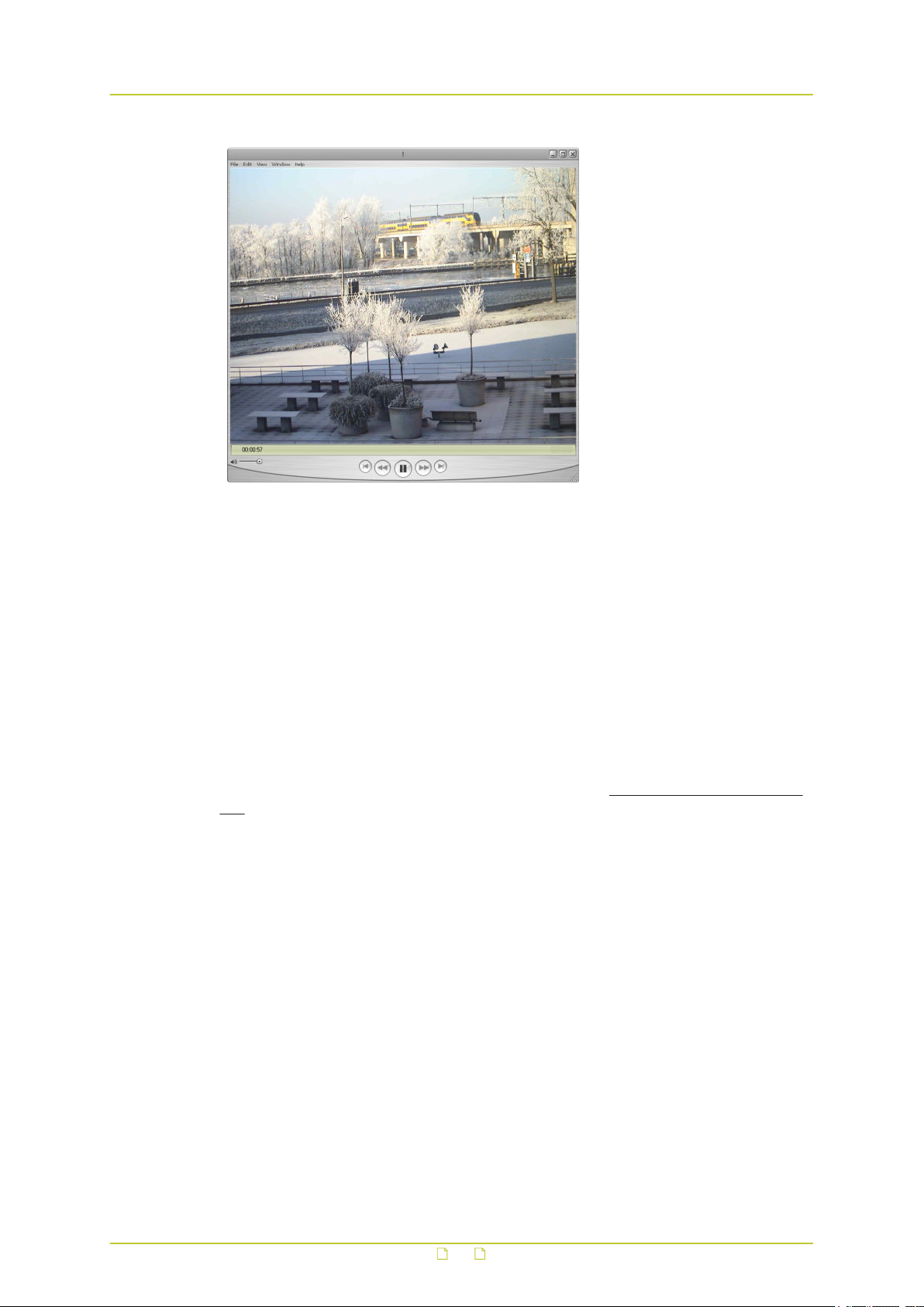
A BC840-MC video stream viewed in QuickTime
5.2 Transfer via UDP or TCP
The BC840-MC supports the following types of streaming.
● UDP/IP (multicast and/or unicast)
● TCP/IP (RTP, RTP over RTSP, RTP over RTSP over HTTP)
The BC840-MC reports to the client that it supports transfer over UDP and TCP. The choice is
made on the client side. In VLC, for example, using a TCP connection can be forced
(Preferences > Inputs and Codecs > Network > RTP over RTSP (TCP)).
For details on controlling BC840-MC media streams through HTTP and RTSP, refer to the SPI
specification. You can download this HTTP API specification at www.tkhsecurity.com/supportfiles.
20
Page 21
6 Access the webpages
The webpages of the BC840-MC offer a user-friendly interface for configuring its settings and
viewing live video over the network. This chapter explains how to connect to the web interface
of the unit.
In This Chapter
6.1 System requirements............................................................................................ 21
6.2 Connect via web browser....................................................................................... 21
6.3 Find the unit with Device Manager...........................................................................22
6.4 Connect via UPnP..................................................................................................23
6.5 Log on to the unit................................................................................................. 23
6.1 System requirements
To access the webpages of the BC840-MC you need the following.
● A PC with a web browser installed.
● An IP connection between the PC and the BC840-MC.
6.2 Connect via web browser
To connect to the unit via your web browser
1 Open your web browser.
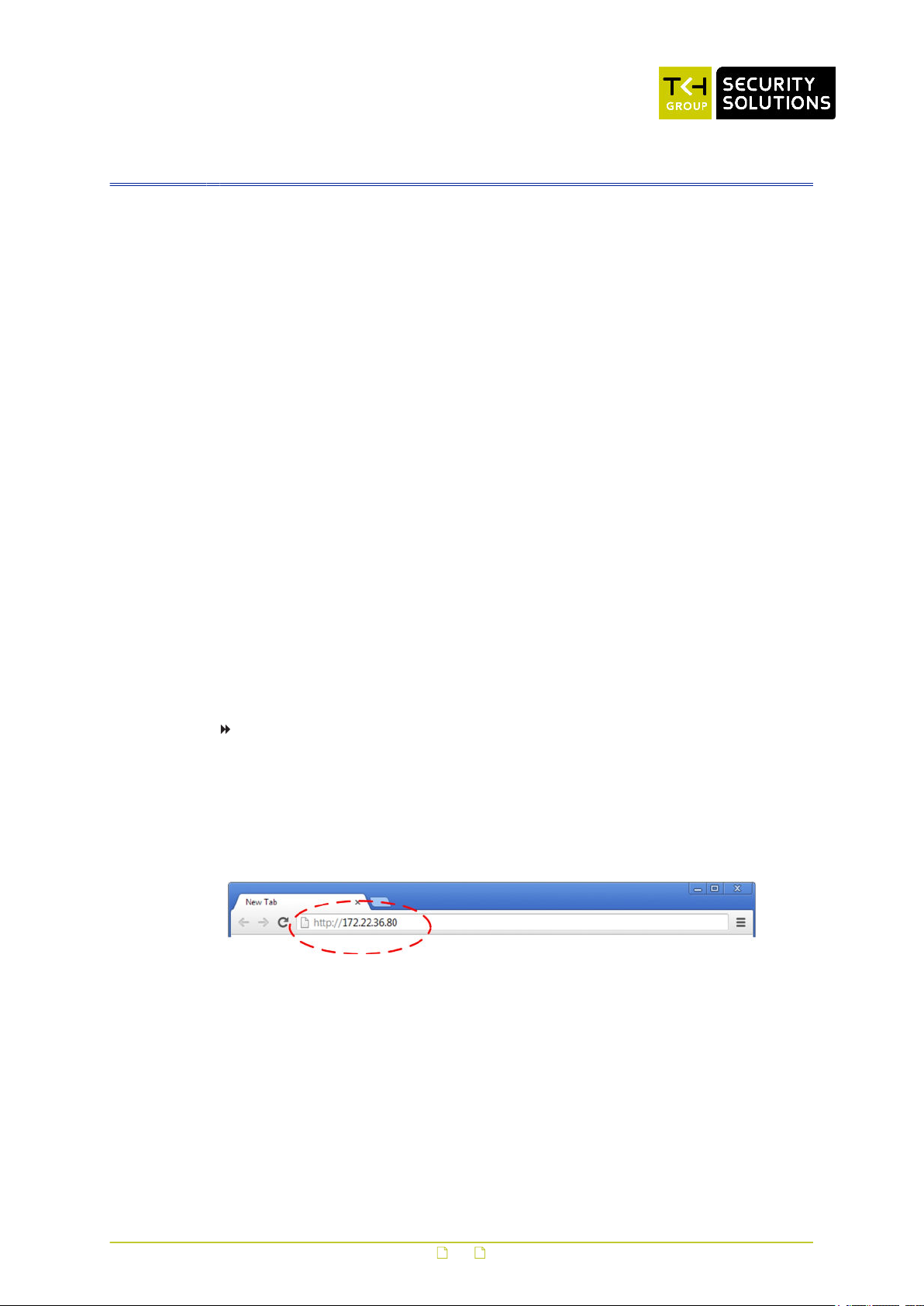
2 Type the IP address of the BC840-MC in the address bar, and then press ENTER.
If your network configuration is correct you are directed to the login page of the unit.
If the page is not displayed correctly, make sure that JavaScript is enabled in your web
browser (see Appendix: Enable JavaScript).
Type the IP address of the BC840-MC in the address bar of the browser
21
Page 22
Access the webpages
6.3 Find the unit with Device Manager
Device Manager is a Windows-based software tool that you can use to manage and configure
TKH Security IP cameras and video encoders. The tool automatically locates these devices and
offers you an intuitive interface to set and manage network settings, configure devices, show
device status, and perform firmware upgrade.
To install Device Manager
1 Download the latest version of Device Manager at www.tkhsecurity.com/support-files.
2 Double-click the setup file.
3 Follow the installation steps to install the software.
To connect to the unit via Device Manager
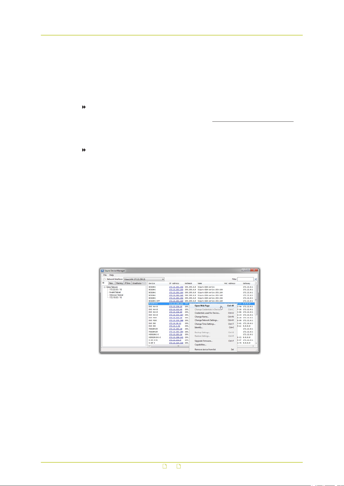
1 Start Device Manager
The network is scanned and detected devices appear in the List View pane.
2 If multiple network adapters exist, select the appropriate adapter to scan the network
that you wish to connect to.
3 To refresh the List view pane, click the Rescan now button.
4 Use the tabs in the Tree View pane to define the scope of your search.
5 Click the column headings in the List View pane to sort devices by type, IP address, or
name.
6 Use the Filter box, to search for a specific series or model.
7 To connect to the webpages of the BC840-MC, double-click its entry in the device list,
- or -
Right-click the entry, and then click Open Web Page.
The login page of the BC840-MC is opened in your web browser.
Connect to a device via Device Manager
22
Page 23
Access the webpages
6.4 Connect via UPnP
Universal Plug and Play (UPnP) support is enabled by default on the BC840-MC. With the UPnP
service enabled in Windows (see Appendix: Enable UPnP in Windows), you can access the unit
from Windows Explorer.
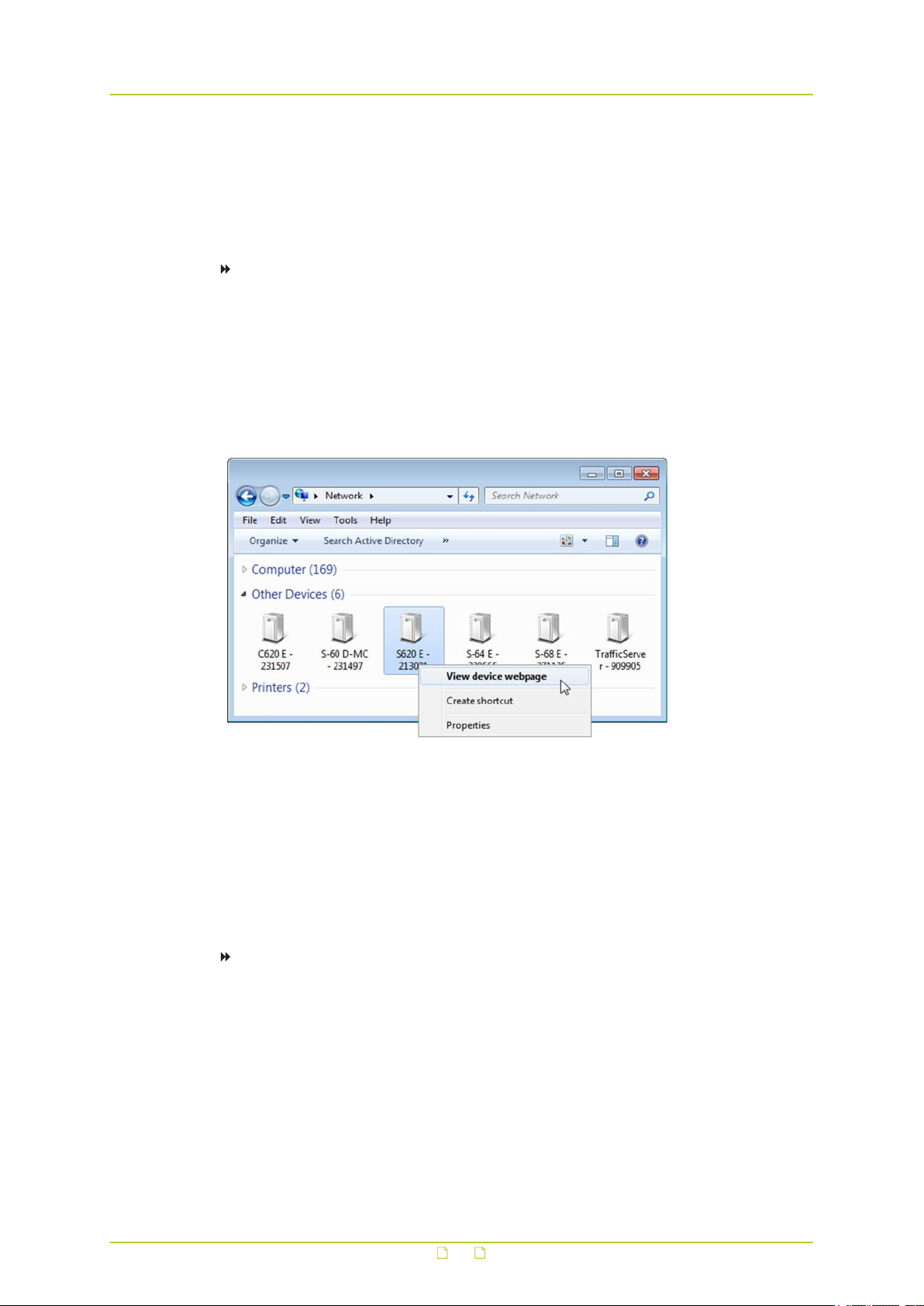
To connect to the unit via UPnP
1 In Windows Explorer, open the Network folder.
Detected devices in the same subnet as the computer are displayed, including TKH
Security codecs and cameras with UPnP support.
2 Double-click the BC840-MC,
- or Right-click the unit, and then click View device webpage.
The login page of the BC840-MC is opened in your web browser.
Connect to a device via Windows Explorer
For more information about UPnP, see Auto Discovery (Device Management chapter).
6.5 Log on to the unit
Users with a valid account for the BC840-MC can log on to the unit.
To log on to the BC840-MC
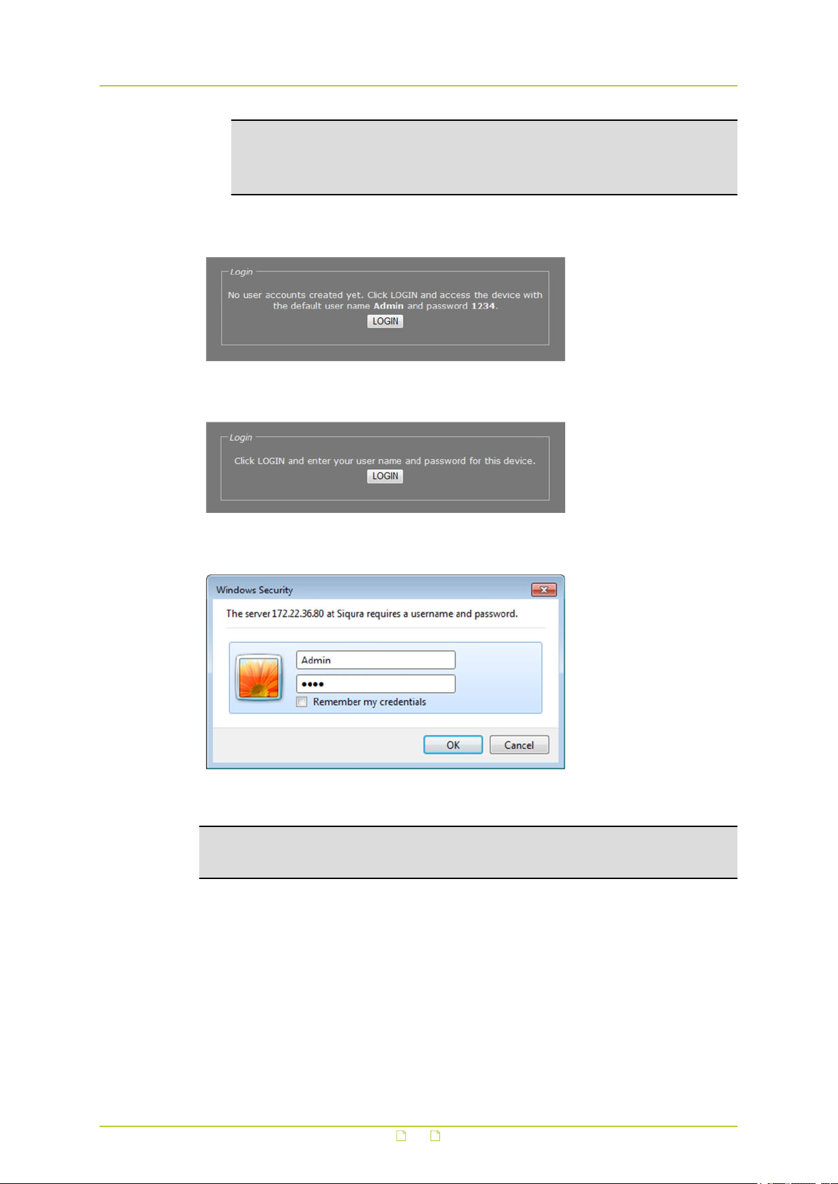
1 On the Login page, click LOGIN.
2 Log on with the account that was created for you.
User name and password are case sensitive.
The default user name set at the factory for the BC840-MC is "Admin" with password
"1234".
23
Page 24
Access the webpages
3 Click OK or press ENTER.
Access possible with default Admin account only (default Admin
password unchanged)
Note: To prevent unauthorised access from people using the default account, we
recommend that the administrator changes the default password after first login and
creates separate user accounts as needed. This also removes the default account
details from the login screen.
On successful login, the Live Video page appears.
Access possible with the user account created for you (default Admin
password has been changed)
Connect dialogue box
Note: The appearance of the BC840-MC webpages and dialogue boxes is determined by the
operating system and web browser used on the host PC. Therefore, some of the screenshots
in this manual may slightly differ from what you actually see on your screen.
24
Page 25
7 Navigate the webpages
This chapter introduces the webpages and common elements found on them. It also discusses
user account types and associated access levels.
In This Chapter
7.1 Menu...................................................................................................................25
7.2 Access control...................................................................................................... 25
7.3 Webpage elements................................................................................................26
7.1 Menu
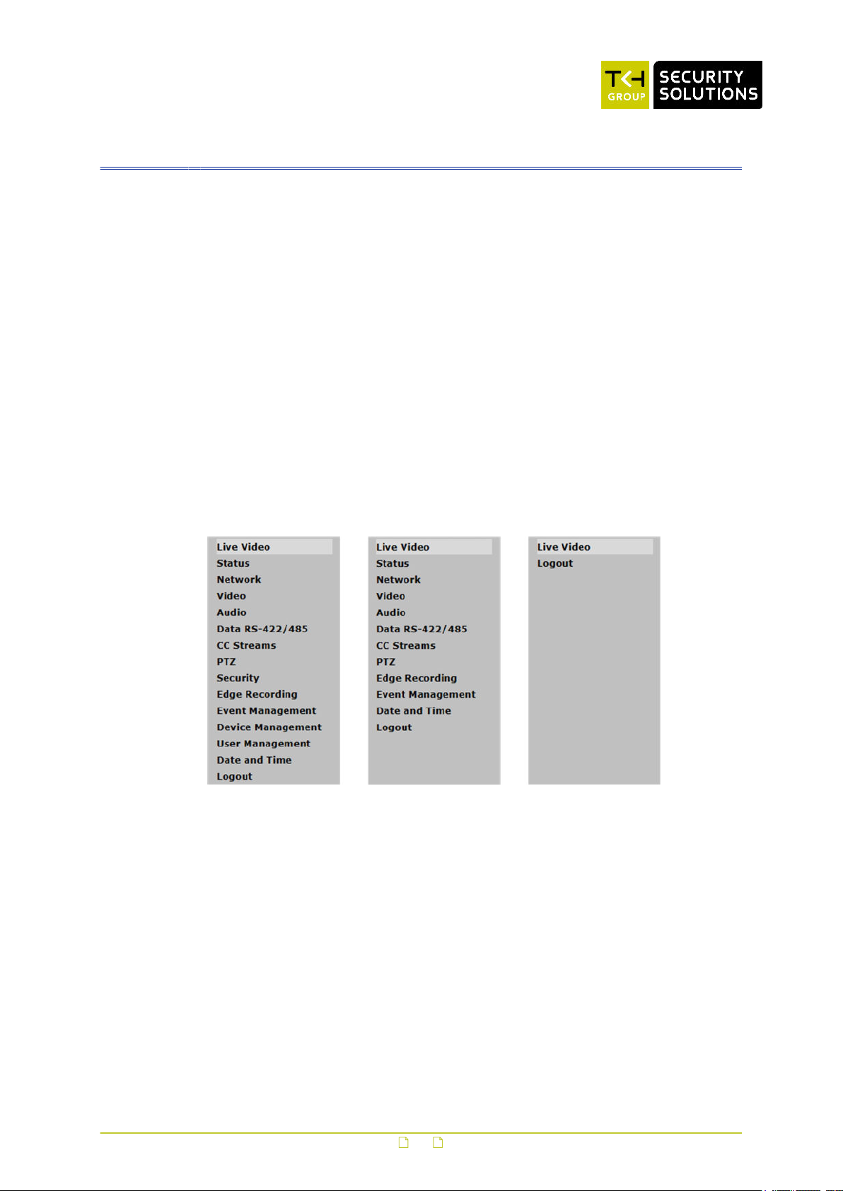
Use the menu on the left of each webpage to go to the other pages.
● Click the option associated with the user or device settings you want to view or configure.
● Click Live Video to reopen the home page of the BC840-MC.
● Click Logout to log out the current user and display the Login box.
BC840-MC menus available to (from left to right) Admin, Operator, and Viewer accounts
7.2 Access control
Whether a specific BC840-MC webpage is available to you on the navigation menu depends on
the user account you logged in with. The unit supports three account types with associated
access levels.
25
Page 26

Navigate the webpages
Account User rights
Admin Full access to all pages. Create, edit, and delete user accounts on
User Management page.
Operator Access to device configuration pages. No access to Device
Management, User Management, and Security.
Viewer Home page only. View live video.
7.3 Webpage elements
Apart from the menu, the webpages share the following features.
● Sections are used to organise parameters and their values.
● Buttons (see below) appear in sections with editable fields.
● Tabs are used to organise page content.
● Check boxes enable you to select features.
This Button Does This Note
Writes changes to the unit.
Undoes unsaved changes and
shows values as they were
before editing.
Opens the Advanced Settings
section with additional settings.
Closes the Advanced Settings
section.
Some sections (for example, those
on the VMD tab of the Video page)
do not have Save and Cancel
buttons. Changes you make here
are immediately written to the
device.
Important: Be aware that
configuring Advanced Settings
requires in-depth understanding of
the impact of your changes on the
workings of your BC840-MC. If in
doubt, do not change the default
values.
26
Page 27

8 View live video via browser
On the Live Video page, you can view live video from the BC840-MC and - if PTZ functionality
is implemented - control the camera from your web browser.
In This Chapter
8.1 Activate Live View.................................................................................................27
8.2 View live video..................................................................................................... 28
8.3 Use your browser for PTZ control............................................................................ 29
8.1 Activate Live View
Live View inactive
The Live View function is inactive when you open the Live Video page.
To activate Live View
● Click Play LiveView>>.
27
Page 28
View live video via browser
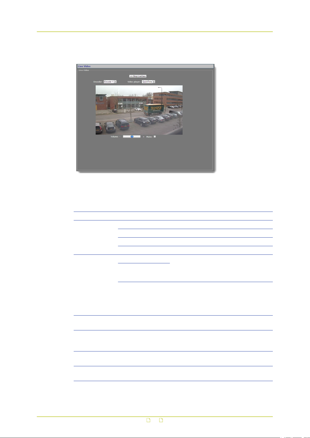
8.2 View live video
Live View activated
With Live View enabled, the Live Video section includes the following items.
Item Description
<<Stop Live View Closes the preview.
Encoder The video encoder used to encode the images seen in the preview.
Encoder 1/2 H.264/MJPEG encoding
Encoder 3/4 MPEG-2/4 encoding
Live View Live View encoding
Video player QuickTime The video player plug-in used for the previews
VLC
No Player BC840-MC supports QuickTime and VLC. If
Refresh rate Live View encoder
mode only
Preview Shows live images from the camera as encoded by the selected
encoder. Encoder 1-4 previews are streamed over RTSP. Live View
encoder previews are transported to the web page using HTTP.
Volume Encoder 1-4 mode
only
Mute Encoder 1-4 mode
only
on this page and the Video page. Note that
QuickTime does not support H.264 High
Profile mode.
neither is detected on the host machine the
Video player list has a “No Player” indication.
For more information, see Appendix: Video
Player Plug-In Installation.
Indicates the current refresh rate of the
webpage.
Move the slider to control audio volume.
Select/clear this check box to mute/unmute
audio.
28
Page 29
View live video via browser
Aspect ratio
Live video can be shown with 16:9 or 4:3 aspect ratio. You can change the aspect ratio on the
Image tab of the Video page.
Enable an encoder
The preview shows images from the selected encoder, unless the specific encoder is disabled.
You can enable and disable encoders on the Video page.
Enable audio
If the audio controls are not available in Encoder # mode, go to the Audio page and make
sure that audio is enabled and properly configured.
Audio Disabled warning
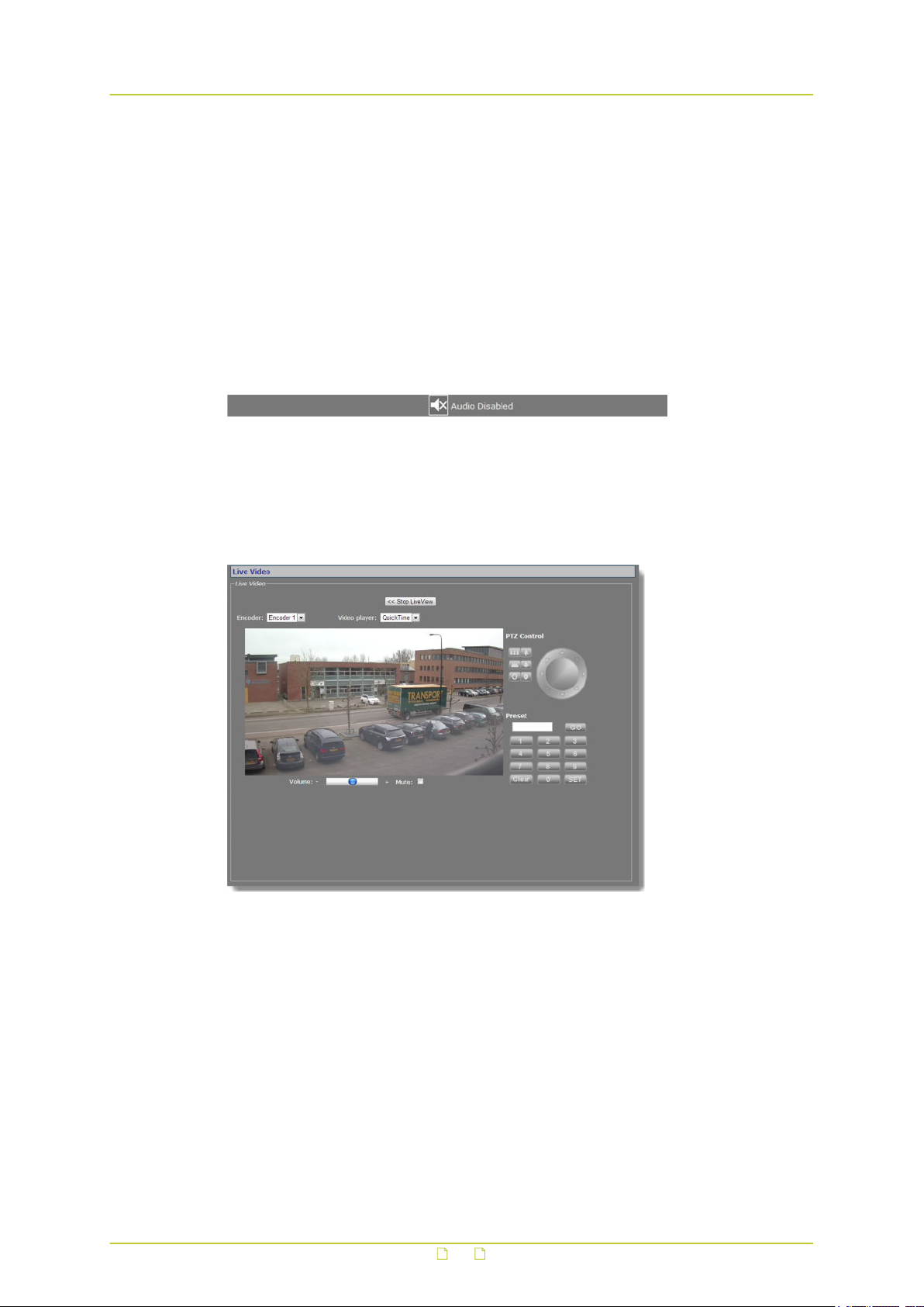
8.3 Use your browser for PTZ control
Live Video page with PTZ Control panel
Display the PTZ control panel
Although the BC840-MC itself does not have PTZ functionality, it can be mounted on a PTZ
mounting bracket which can then be controlled from the BC840-MC's serial data port
(RS-4xx). With a PTZ driver selected on the PTZ webpage, the PTZ control panel is available
on the Live Video page. If the BC840-MC supports the PTZ driver, you can use the panel to
control the camera and manage the presets via the mounting bracket. PTZ drivers not
included in the driver list on the PTZ page can be uploaded to the BC840-MC via PTZ Driver
Management on the same page.
29
Page 30
View live video via browser
PTZ control
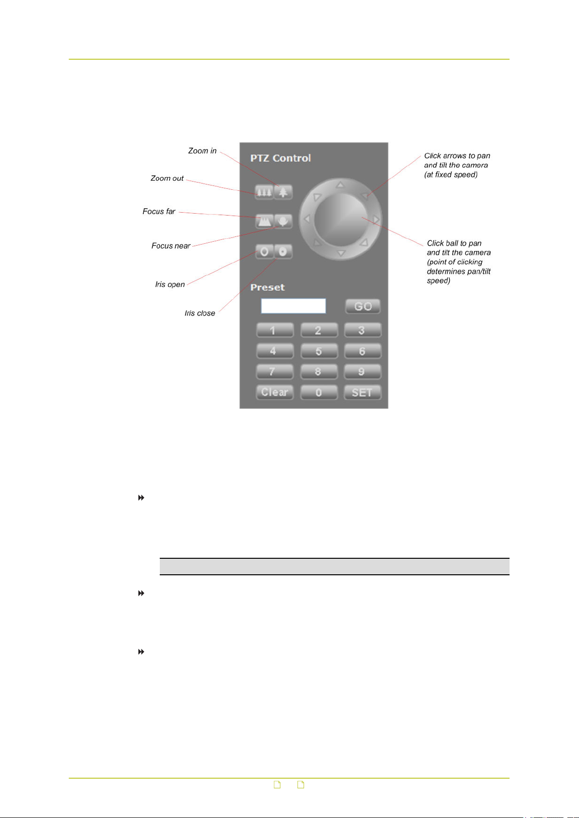
Use the upper section of the PTZ Control panel to pan, tilt, zoom, and focus the camera, and
control the iris, as shown in the following figure.
PTZ Control panel
Preset
Use the Preset section to define and recall preset camera positions.
To enter and save a preset camera position
1 Click the appropriate number button(s) to enter the preset number.
2 Adjust the position of the camera for the desired view.
3 When satisfied with the position, click SET.
Note: The SET button is not available to users with Viewer rights.
To recall a preset camera position
1 Click the appropriate number button(s) to enter the preset number.
2 Click GO.
To erase a preset camera position
1 Call the preset.
2 Press Clear.
3 If desired, override the preset with a new preset position.
30
Page 31

9 Status
The status information and measurements on the Status page may provide helpful clues to
identify and troubleshoot technical issues.
In This Chapter
9.1 View status information......................................................................................... 31
9.2 View measurements data....................................................................................... 32
9.1 View status information
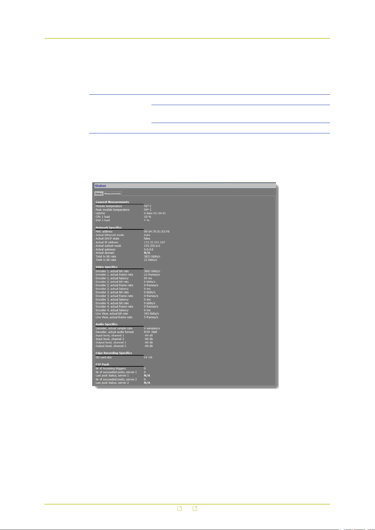
Status page: a snapshot with automatic page updating
9.1.1 Stream states
The Status tab provides information on the stream states of video and audio streams.
Stream state Description
OK There is nothing wrong with the stream. Note that if the video
Idle The transmitter/receiver is not enabled.
Waiting The transmitter/receiver has lost its stream connection.
signal is removed from the video input on the encoder side, the
Decoder rx state is still reported as OK, since the video transmitter
is sending a stream - that is, a No Video image - to the decoder.
Possible causes:
● An incorrect port number.
● The transmitter on the encoder side is not enabled.
● No FloodGuard packets have been received for more than three
seconds. For details on the FloodGuard flooding prevention
mechanism, see the note on FloodGuard in the Video chapter.
31
Page 32
Status
9.1.2 Edge recording
The Edge recording section shows whether an SD card is present and if it can be accessed.
Item Description
SD card status OK SD card present and functioning.
Error Unable to access SD card. Possible damage to
card, connectors, or slot.
Not present No SD card detected.
9.2 View measurements data
Status > Measurements
9.2.1 General, network, and stream measurements
The Measurements tab shows general measurements, such as the module temperatures
(current and peak) and the module uptime.
You also find network specifics here, such as the MAC address, the actual IP address, the
network load from this module, the load information per processor, and signal stream-specific
details.
32
Page 33

Status
9.2.2 SD card size
Note that the storage capacity available for edge recording is limited to 75% of the actual SD
card size given under Edge Recording Specifics - that is, for example, 24 GB of a 32 GB SD
card. This limit is to prevent slow read/write speeds.
9.2.3 FTP Push
You can use the FTP Push data to monitor the FTP Push process.
33
Page 34
10 Network
On the Network page, you can change the network settings of the BC840-MC. In this chapter,
you learn how to set a valid, fixed IP address and, alternatively, how to have an IP address
automatically assigned by a DHCP server.
In This Chapter
10.1 Network settings................................................................................................. 34
10.2 Advanced...........................................................................................................35
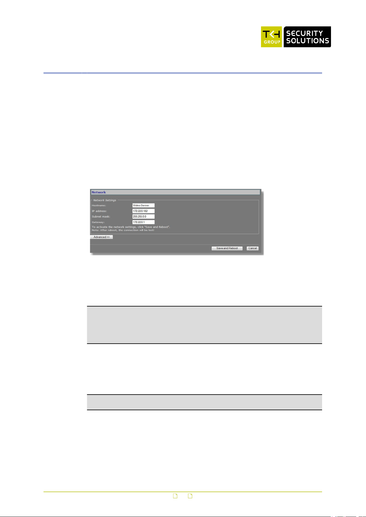
10.1 Network settings
Network page
On the Network page, you can set the name of the unit, the IP address, the subnet mask, and
the gateway IP address. For correct functioning of the BC840-MC, it is vital to set its network
addressing to be compatible with the subnet it is hooked into.
Note: The factory-set IP address of the unit is in the 10.x.x.x range with a subnet mask of
255.0.0.0. Achieving initial communication with the unit requires that the network adapter of
the browsing PC is set to the factory-default subnet of the BC840-MC. Once you have made
the webpages accessible in this way, you can use the Network page to change the default
network settings to the desired settings.
For IP address input to be valid, the unit's IP address:
● must be within the 1.0.0.1 – 223.255.255.254 range
● cannot start with 127 (reserved for loopback on local host)
After changing IP settings, do not forget to save the new settings and reboot the unit (see
chapter Device Management).
Important: It is essential to set at least the IP address and subnet mask correctly. Keep
these value on record, otherwise management of the unit will require special software.
34
Page 35

Network
10.2 Advanced
Network > Advanced
10.2.1 Services
Item Description
RTSP server
enable
RTSP server port This is the port number used to contact the RTSP server. The default
10.2.2 Network
Item Description
DHCP enable Allows assigning of the IP address by a DHCP server instead of using static
Ethernet mode Transmission mode and speed.
MTU size Set to Ethernet (1500) by default. Maximum Transmission Unit (MTU) is
Select this check box to enable the BC840-MC to act as a server in
RTSP media sessions.
transport layer port number for the RTSP protocol is 554 for both UDP
and TCP transports.
IP addressing.
Auto Autonegotiation (default).
10 HDX Half duplex, 10 Mbit.
10 FDX Full duplex, 10 Mbit.
100 HDX Half duplex, 100 Mbit.
100 FDX Full duplex, 100 Mbit.
the maximum size (in bytes) of an IP packet that can be transmitted over
the network without dividing it into pieces. An MTU size that you select
here must be supported on the other side of the link.
35
Page 36
11 Video
On the Video page, you can configure settings for camera setup, video encoding, on-screen
display, video motion detection, image posting via FTP, camera health monitoring, tampering
detection, and privacy masks.
In This Chapter
11.1 Image............................................................................................................... 36
11.2 Video encoding overview...................................................................................... 45
11.3 Encoder 1.......................................................................................................... 46
11.4 Encoder 2.......................................................................................................... 61
11.5 Encoder 3/4....................................................................................................... 62
11.6 Live View........................................................................................................... 68
11.7 OSD.................................................................................................................. 70
11.8 VMD.................................................................................................................. 75
11.9 FTP Push............................................................................................................80
11.10 Image Monitor.................................................................................................. 83
11.11 Tamper Detect.................................................................................................. 90
11.12 Privacy Mask.....................................................................................................97
11.1 Image
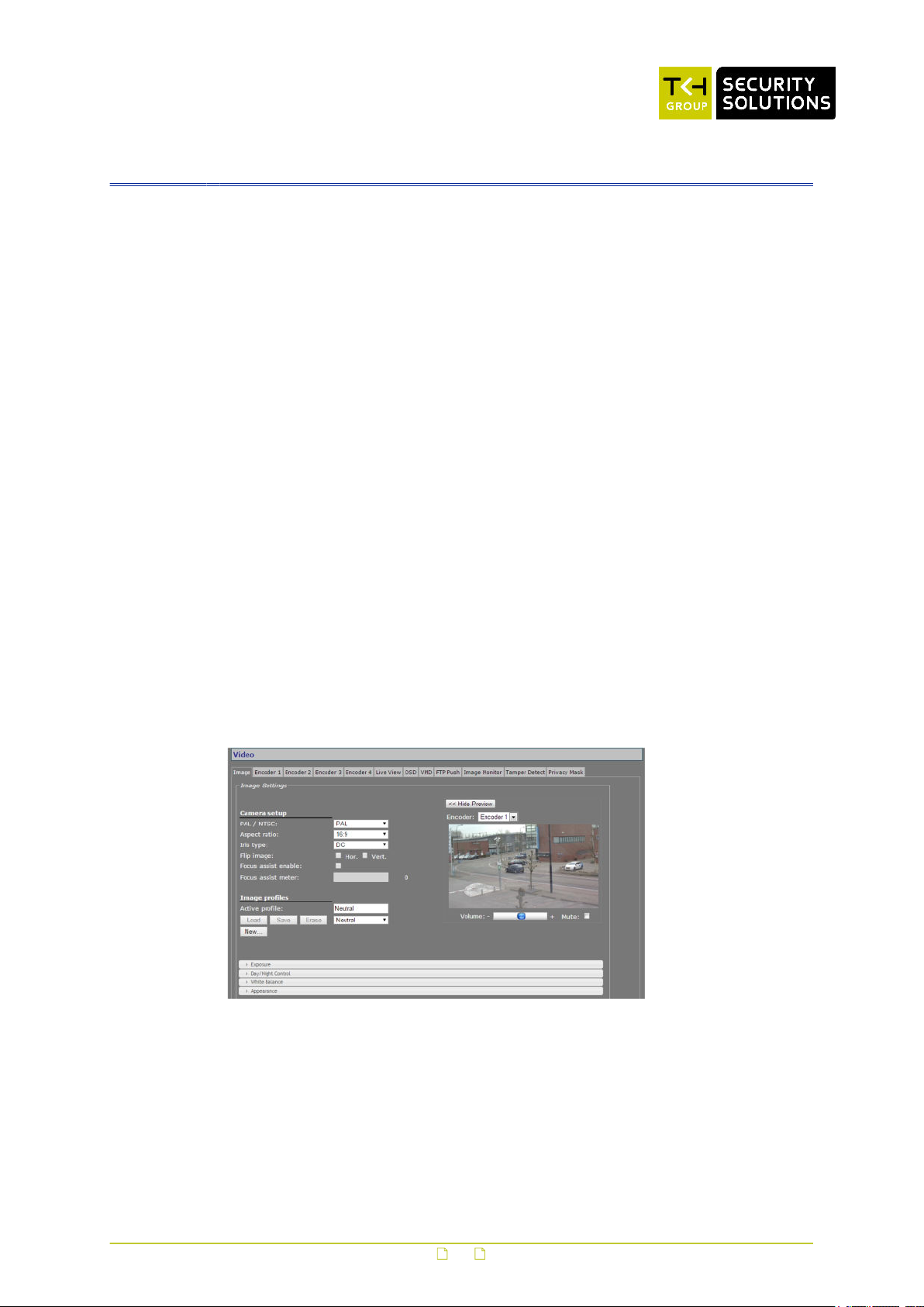
Video > Image
Tab layout
Settings on the Image tab are grouped in the following categories.
● Camera setup
● Image profiles
● Exposure
36
Page 37

Video
● Day/Night Control
● White Balance
● Appearance
Accordion style menus at the bottom of the Image tab are opened/closed by clicking the
menu's title bar.
Preview
Click Show Preview>> to open the preview and see the effect of your current settings.
11.1.1 Camera setup
Item Description
PAL/NTSC PAL Sets the video display standard. Affects the
Aspect ratio Sets the proportional relationship between the width and the height of
Iris type DC Activates electrical iris control. The camera
Flip image Horizontal Rotates the image around a vertical axis
Focus assist
enable
Focus assist meter With Focus Assist enabled, a blue bar indicates the focus level. A white
NTSC
the preview images shown on the BC840-MC webpages.
16:9 Produces a widescreen format (letterbox-like)
4:3 Produces a box-like picture. Note that the
Manual To be selected for lenses without iris setting
Vertical Rotates the image around a horizontal axis
Activates the Focus Assist function. Alternatively, you can also press
the Focus Assist button on the back of the camera. Using Focus Assist
is described below.
bar with the same function appears as an overlay over the image.
selectable frame rates on the encoder tabs
(PAL: 1-25 fps; NTSC: 1-30fps). Note that
this setting also determines the video
standard on the analogue output on the back
of the camera.
picture.
video will be cropped on the left and right to
fit within the preview.
will automatically handle the level of light
allowed to enter the lens. Select this option
for DC Auto Iris lenses. Video Auto Iris lenses
are not supported.
or manual iris setting.
through the centre of the image (left becomes
right, and vice versa). See pictures below.
through the centre of the image (top becomes
bottom, and vice versa). See pictures below.
37
Page 38
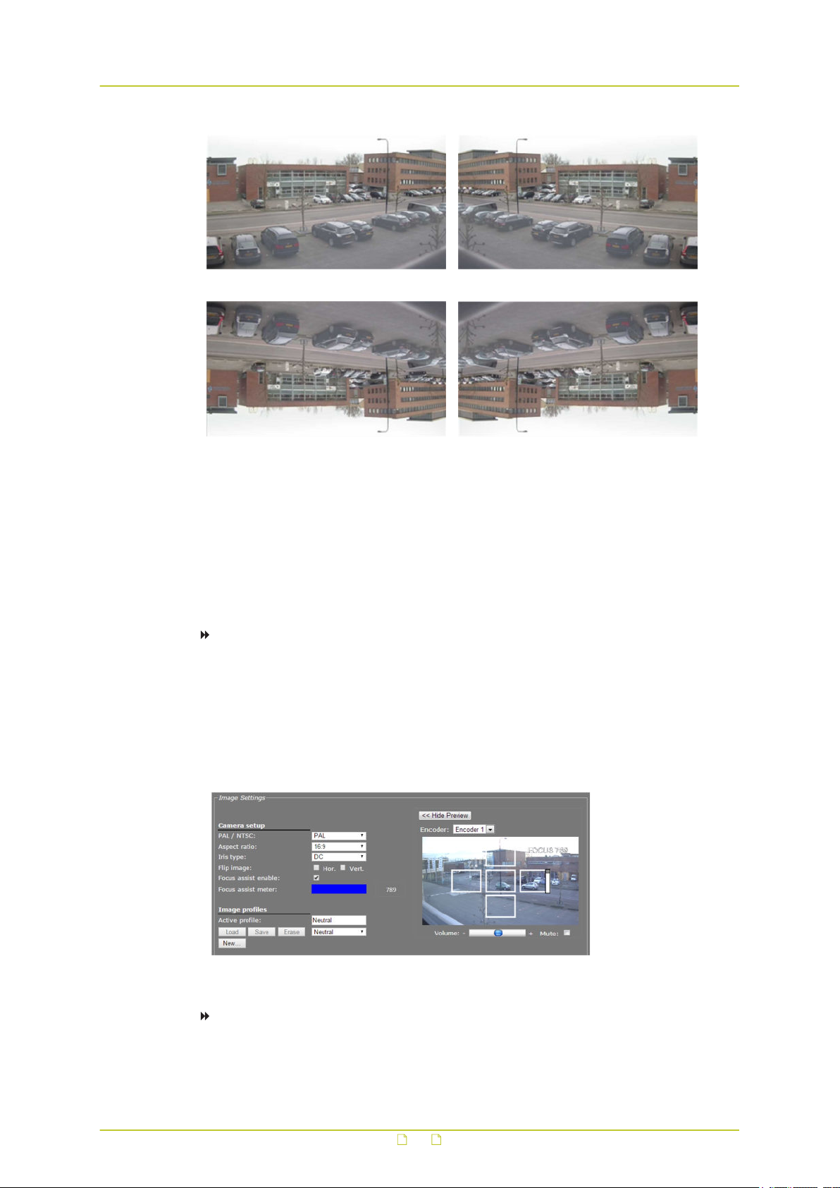
Video
Original image Flip horizontal
Flip vertical Flip horizontal and vertical
11.1.2 Use Focus assist
BC840-MC includes Focus Assist functionality to achieve optimal image quality. Focus Assist
can be used from the Video page but also from the back of the camera body. The latter may
prove useful when setting the focus without a monitor.
To use Focus Assist from the webpage
1 On the Video page, select the Image tab.
2 Under Camera setup, select Focus assist enable.
The focus level is indicated by the blue Focus assist meter bar. The meter is also
overlaid over the image as a vertical white bar.
3 Aided by the feedback from the Focus assist meter, adjust the focus on the lens.
The greater the detail in the scene, the higher the number on the Focus assist meter.
Focus assist meter enabled
To use Focus Assist from the camera body
1 To activate Focus Assist, turn the focus ring of the lens all the way in one direction, and
then press the white button on the back of the camera housing.
38
Page 39

Video
The Focus LED - also on the back of the housing - shines orange, indicating that Focus
Assist has not registered a maximum sharpness value yet.
2 Slowly turn the focus ring of the lens until the LED shines red.
3 Next, turn back the focus ring to find the point where the Focus LED shines green.
This is the point where the camera is properly focused.
LED state Indicates Action
Orange Focus Assist has not registered a
Red Focus Assist has registered a
Green The camera is properly focused. None
11.1.3 Image profiles
Video > Image > Image profiles
Image profiles
The accordion style menus at the bottom of the Image tab allow you to configure Exposure,
Day/Night, White Balance, and Appearance settings. Combinations of these settings can be
saved to and loaded from a profile. In addition to custom profiles created by the user, the
profile list includes preset profiles for specific purposes. When a profile has been selected,
changing one of its defined parameters sets the Profile box to '--'.
maximum focus value yet.
maximum focus value, but is not
properly focused yet.
Turn the focus ring of the lens all
the way from left to right until a
maximum value is seen.
Slowly turn the focus ring until the
Focus LED shines green.
Item Description
Active profile The active combination of settings.
Load Activates the selected profile.
New Enables you to enter a name for a new profile.
Save Saves and activates the selected profile.
Erase Removes the selected profile.
Profile list Available profiles.
11.1.3.1 Image profile management
To create a custom image profile
1 On the Video page, click the Image tab.
2 In the Image profiles section, click New.
3 Enter a name for the new profile, and then click OK.
39
Page 40

Video
4 Configure the required settings in the Exposure, Day/Night Control, White Balance,
and/or Appearance sections.
5 Click Save.
To load an image profile
1 On the Video page, click the Image tab.
2 In the Image profiles section, click to open the profile list.
3 Select the profile, and then click Load.
The profile displays in the Active profile box and the camera adopts the new settings.
To erase an image profile
1 On the Video page, click the Image tab.
2 In the Image profiles section, click to open the profile list.
3 Select the profile, and then click Erase.
The profile is removed from the profile list.
11.1.4 Preview
Video > Image > Preview
Item Description
Show Preview>> Click to view live images and see the effect of the current settings.
<<Hide Preview Closes the preview. This may improve webpage responsiveness.
Encoder The encoder handling the images seen in the preview.
Volume Encoder #
mode
Mute Encoder #
mode
Move the slider to control audio volume.
Select/clear this box to mute/unmute audio.
40
Page 41

Video
11.1.5 Exposure
Exposure is the amount of light received by the image sensor and is determined by how wide
you open the lens diaphragm (iris adjustment), by how long you keep the sensor exposed
(shutter speed), and by other exposure parameters. In the Exposure section of the Image tab,
you can define a variety of exposure settings.
Video > Image > Exposure
41
Page 42

Video
Item Description
Gain control
mode
Actual gain Auto gain control
Manual gain Manual gain control
Max auto gain Auto gain control
Shutter mode The shutter speed determines how long the image sensor is exposed to
Min shutter
time
Max shutter
time
Manual shutter Manual shutter
Transition
speed
EV
compensation
Metering area Auto, Center, Left, Right, Top, Bottom Defines what zone of the
Backlight
compensation
Wide dynamic
range
Gain is an electronic way of increasing the video signal to control the
exposure. Higher gain values introduce more noise in the image.
Auto The camera automatically controls gain. A
maximum can be set via the Max auto gain
parameter.
Manual Enables gain configuration via the Manual gain
parameter.
Shows current gain level.
mode only
Drag the slider to set a gain value manually.
mode only
Drag the slider to set an upper limit for automatic
mode only
light.
Auto The camera automatically controls the shutter
Manual Enables shutter speed configuration via the
Auto shutter mode
only
Auto shutter mode
only
mode only
Slow, Medium, Fast Controls the transition time span between
The camera is calibrated to expose images correctly for scenes that have
a mix of light and dark areas. Use exposure value (EV) compensation for
scenes where the major part of the image is either very bright or very
dark. For a very bright scene (snow, for example), set the EV value as a
positive number (+1/3 EV ~ +2 EV). For very dark scenes, set a
negative EV value (-1/3 EV ~ -2 EV).
In images with a bright light source behind the subject of interest, use
backlight compensation to adjust the exposure of the entire image to
expose the subject in the foreground properly.
In images with indoor and outdoor contrast issues, use wide dynamic
range to adjust exposure in areas of the image to preserve greater
scene detail in both the shadows and highlights of the image.
gain control.
speed. Use Min shutter time and Max shutter
time to set shutter speed limits.
Manual shutter list.
Determines the minimum shutter speed.
Selecting Minimal sets the minimum shutter
speed to 1/10000 s.
Determines the maximum shutter speed.
Enables you to set a shutter speed. To see clear
images in a dark environment, select a slow
shutter speed.
subsequent exposure levels. With a slow setting,
the camera takes more time to adjust to a new
light situation.
image is to have most weight
in measuring the exposure of
the entire scene.
42
Page 43

Video
Item Description
Flicker
reduction
Compensates for flickering caused by discrepancies between the frame
rate (video standard) and the AC frequency of the lighting.
11.1.6 Day/Night Control
With Day/Night Control, the camera can still catch clear images at night. In daylight, the IR
cut filter blocks infrared light for clear images. At night, the IR cut filter is removed to utilise
infrared light; the displayed images will be in black and white.
Video > Image > Day/Night Control
Item Description
Day/night mode Auto Enables day/night switching. The internal circuit
Day Activates the IR cut filter. Camera is set to colour
Night Removes the IR cut filter. Camera is set to black
Transition
threshold
Transition speed Auto mode only Sets the delay the camera takes into account
Auto mode only Sets the threshold for the camera to place/remove
automatically decides when to place/remove the
IR cut filter based on the value of the lighting
conditions as determined by the Transition
threshold.
mode.
and white mode.
the IR cut filter. With a higher threshold value, the
camera switches to night mode at lower light
levels (higher gain value). With a lower threshold
value, the camera switches to night mode at
higher light levels (lower gain value).
when switching from day to night mode and vice
versa. Using a higher value here prevents the
camera to trigger on for example headlights of a
car temporary shining directly into the camera at
night.
11.1.7 White Balance
A digital camera needs to find a reference color temperature, which is a way of measuring the
colour of a light source as a basis for calculating all the other colours. The unit for measuring
this ratio is in degree Kelvin (K). You can select one of the white balance control modes
according to the installation condition. The following table shows the colour temperature of
some typical light sources.
43
Page 44

Video
Light source Colour temperature in K
Cloudy sky 6,000 to 8,000
Noon sun and clear
sky
Household lighting 2,500 to 3,000
75-watt bulb 2,820
Candle flame 1,200 to 1,500
Light source reference
Video > Image > White Balance
6,500
Item Description
White balance
mode
White balance
adjust
White balance red Sliders to adjust colour temperatures. Drag the
White balance
blue
11.1.8 Appearance
ATW outdoor Use this option for outdoor applications.
ATW indoor Use this option for indoor applications.
AWB Can be applied to scenes without distinct white
areas. A possible alternative for ATW outdoor and
ATW indoor if you cannot achieve a satisfactory
white balance with these.
Manual/Hold Activates the Adjust Now button, and the White
balance red and White balance blue sliders. Use
these for manual white balance setting.
Manual/Hold
mode only
Press Adjust Now to recalculate the white balance
according to the current image and then lock it.
sliders to increase/decrease the red/blue values in
the image while observing the preview.
Video > Image > Appearance
44
Page 45
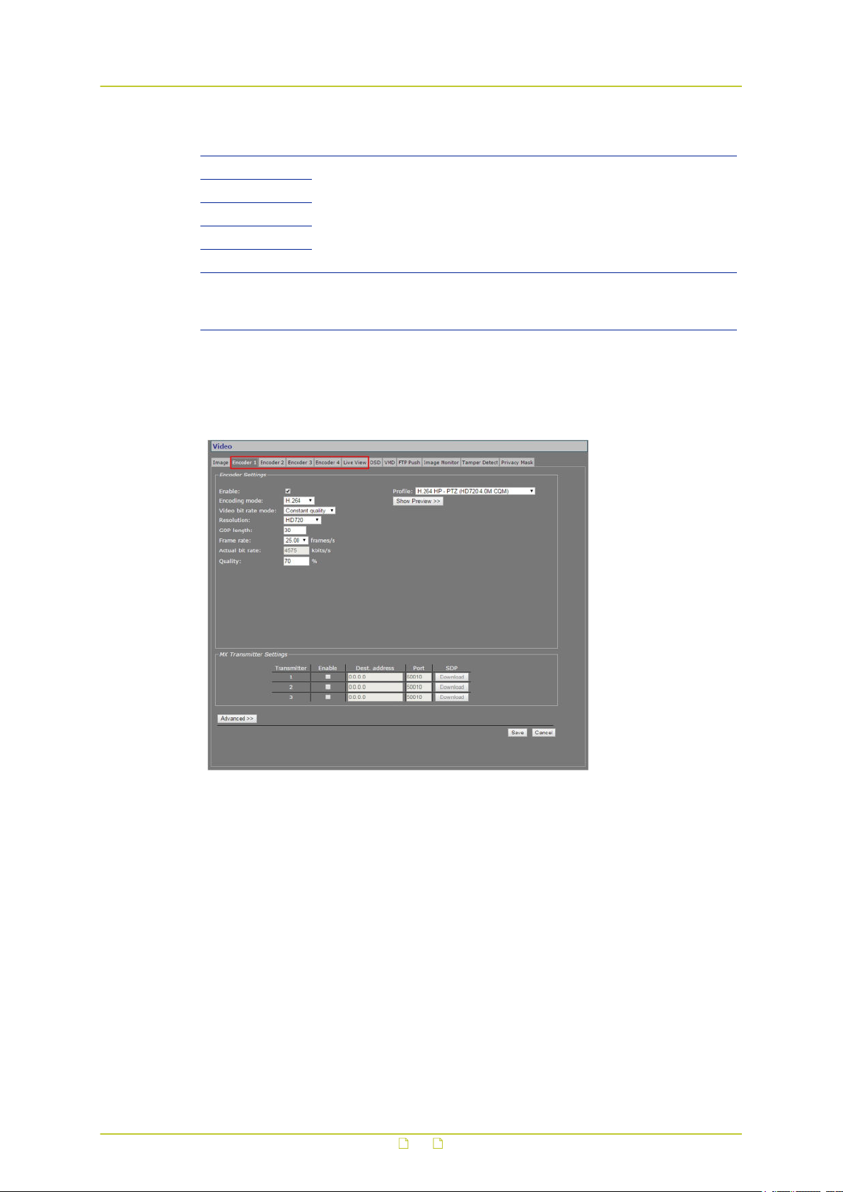
Video
Item Description
Color saturation Drag the slider or enter values into the boxes to adjust current settings
Hue
Contrast
Brightness
Sharpness
Adaptive noise
filter
aided by the visual feedback from the preview. Settings entered here
apply to all video encoders.
This function monitors the amount of noise in the image. In dark
images with rising noise levels introduced by increased Gain, it
gradually intervenes to reduce the noise.
11.2 Video encoding overview
Encoder tabs on Video page
Video encoding
The BC840-MC features a built-in, multicodec video server. Four video encoders can
simultaneously generate independent digital video streams with different resolutions and
frame rates. Encoders 1 and 2 can each convert the video signal into H.264 or MJPEG format.
Encoders 3 and 4 can both handle MPEG-2/4 encoding.
Multistreaming
Up to twenty streams can be retrieved using RTSP. A total of twelve copies – three per
independent encoder – can be transmitted to different unicast and/or multicast destinations
using TKH Security's proprietary MX protocol. The BC840-MC supports source-specific
multicast (SSM). MPEG-2/4, H.264, and audio streams can also be transmitted to multicast
destinations using the Session Announcement Protocol (SAP).
45
Page 46
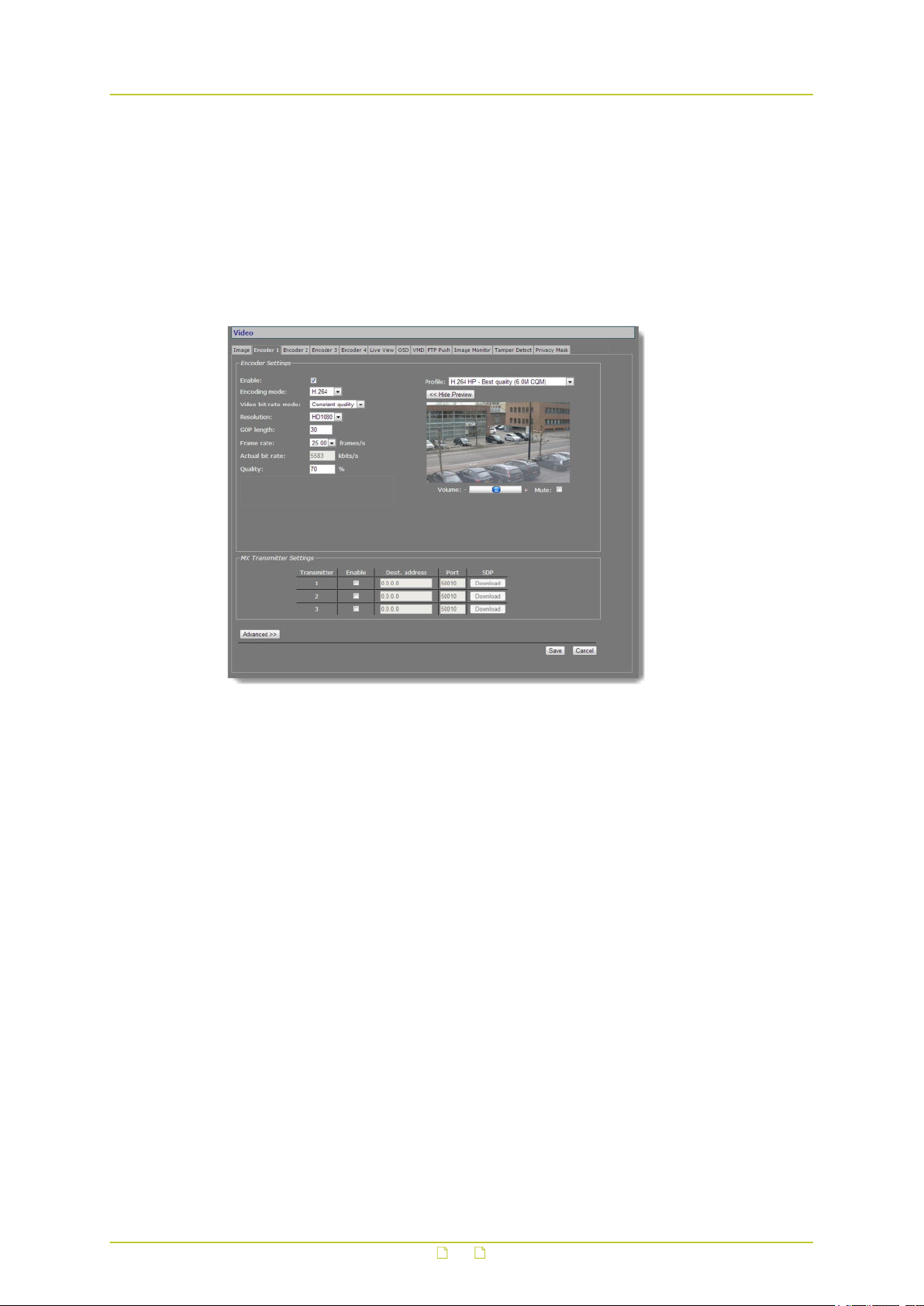
Video
Live View encoder
The Live View encoder can convert the analogue video input signal to (M)JPEG format for
streaming to web applications or remote devices using the HTTP protocol. Via FTP Push, JPEG
images can also be posted on an FTP server.
11.3 Encoder 1
Video > Encoder 1
46
Page 47

Video
11.3.1 Encoder Settings
Item Description
Enable All encoders are enabled by default. Use this check box to disable/re-
Encoding mode H.264 or
● To enable and configure UDP/MJPEG streaming, select MJPEG from
● To transport JPEG over HTTP and/or use the Live View previews in
Video bit rate
mode
Resolution Indicates the number of pixels that can be displayed in each
GOP length Distance in frames between two I-frames.
Frame rate PAL: 1-25 fps; NTSC: 1-30 fps. Selectable rates are determined by
Bit rate Constant bit
Actual bit rate Constant
enable this specific encoder.
The method used to compress the video signal.
MJPEG
The BC840-MC can stream (M)JPEG over UDP and HTTP.
the Encoding mode list and configure settings.
the webpages, go to the Live View tab, enable the Live View
encoder, and configure its settings.
Controls variations in bit rates.
Constant
quality
Constant bit
rate
dimension (width x height).
HD1080 1080p (1920x1080)
1440x1080 1080p (1440x1080)
HD720 720p (1280x720)
960H 960x576 (PAL); 960x480 (NTSC)
D1 720x576 (PAL); 720x480 (NTSC)
VGA 640x480
2CIF 720x288 (PAL); 720x240 (NTSC)
CIF 352x288 (PAL); 352x240 (NTSC)
With Encoder 1 and Encoder 2 both doing H.264 encoding or both
doing MJPEG encoding, the BC840 will simultaneously handle single
full HD encoding up to 30 fps and single CIF encoding up to 30 fps.
Dual full HD H.264 encoding or dual full HD MJPEG encoding is
supported up to 15 fps. For a combination of H.264 encoding and
MJPEG encoding there are no limits. The maximum resolution for Live
View encoding is D1
the video mode (PAL, NTSC) set on the Image tab.
rate mode only
quality mode
only
Keeps the image quality constant, with varying
network load. See Constant Quality Mode (CQM)
configuration (below) for TKH Security's
recommended strategy for controlling image quality.
Keeps network load constant at the cost of varying
image quality. Frames may be skipped.
The speed of the digital transmission - that is, the
amount of information transferred/processed per
unit of time.
This field is dynamically updated with the current bit
rate to provide feedback on the bit rate that is used
on average with the current Quality setting.
47
Page 48

Video
Item Description
Quality Constant
quality mode
only
Profile Preset combinations of settings for specific purposes. When a profile
has been selected, changing one of its defined parameters sets the
Profile box to '--', to indicate that a custom profile has been
configured. When a freely chosen parameter value combination
matches a preset profile, the name of the profile shows in the Profile
box.
Show Preview>> Click to view live images and see the effect of the current settings.
<<Hide Preview Closes the preview. This may improve webpage responsiveness.
Volume Move the slider to control audio volume.
Mute Select/clear this box to mute/unmute audio.
Reflects the amount of compression. Generally
speaking: the higher the quality setting, the lower
the compression ratio and the more bits are
consumed. This means a trade-off has to be found
between the desired quality level and available
bandwidth.
11.3.1.1 Parameter value combinations
Set sensible combinations of video bit rate mode, resolution, GOP length, and frame and bit
rates. When you set and save these values, inappropriate value combinations are 'corrected'
by automatic selection of the closest suitable combination.
Important: If in doubt about the effects of specific encoder settings, you are advised to
select the profile offering the closest match to your required application.
11.3.2 Constant Quality Mode configuration
Constant Quality mode (CQM) can be used in situations with intermittent increases of
movement in camera images. This mode provides better pictures when quickly panning a PTZ
camera, for example. TKH Security recommends the following strategy for Constant Quality
mode configuration.
To configure CQM settings
1 In Encoder Settings, open the Video bit rate mode list, and then select Constant
quality.
2 With the video source connected and the encoder enabled, go to the Quality field and set
the desired quality (range: [0 ... 100%]), aided by the visual feedback in the Preview.
3 Press Save to store your settings.
The Actual bit rate field is dynamically updated with the current bit rate.
4 Determine if the average bit rate used with the current Quality setting is acceptable. If
not, modify the Quality setting.
5 To set the upper limit for the bit rate, open the Advanced Settings section and use the
CQM max bit rate field to specify the maximum bit rate.
Generally, it is not necessary to change the default setting of 6000 kbit/s, unless there
are physical limitations on the network.
6 Press Save to store your settings.
48
Page 49
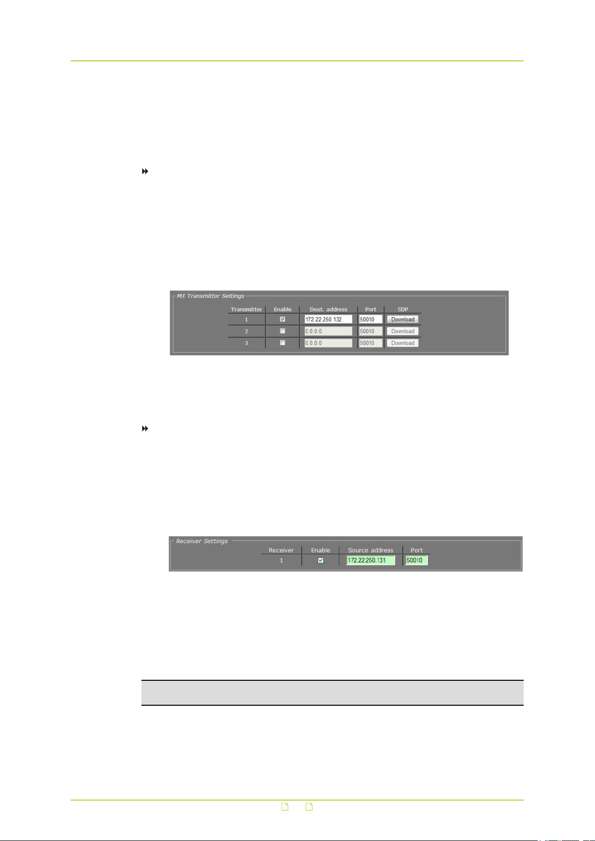
Video
11.3.3 Make a video connection
Creating a video link between a video encoder and a video decoder involves two steps:
● Configuring settings of the encoder
● Configuring settings of the decoder
To configure the encoder settings
1 Open the webpages of the encoder, go to the Video page, and then open the appropriate
Encoder tab.
2 In the MX Transmitter Settings section, specify the destination IP address.
This is the address of the video decoder which will receive the video stream.
3 Enter the port number of the decoder.
For more information about port numbers, see the Port Numbers section.
4 Select Enable, and then click Save.
Video Transmitter Settings (encoder side).
Transmitter 1 enabled, holding the decoder IP address and input port number.
An input port number must be used only once per device.
To configure the decoder settings
1 Open the webpages of the decoder, go to the Video page, and select the Decoder tab.
2 In the MX Receiver Settings section, specify the source IP address.
This is the address of the video encoder which will transmit the video stream.
3 Enter the port number of the decoder.
For more information on port numbers, see the Port Numbers section.
4 Select Enable, and then click Save.
Video Receiver Settings (decoder side).
Receiver 1 enabled, holding the encoder IP address and the decoder input port number.
An input port number must be used only once per device.
With these settings configured correctly, the video link is established. The decoder takes the
video stream from the encoder, detects the video format and uses the appropriate decoding
algorithm to convert the stream to an analogue output signal.
Note: Source and destination IP addresses can be unicast or multicast. For more
information, see the Multicast chapter.
Highlighted fields
The source address and port number fields are highlighted in green when the enabled receiver
receives a stream from the specified source. The two fields are marked in red when no stream
is received with the receiver enabled and correctly configured.
49
Page 50
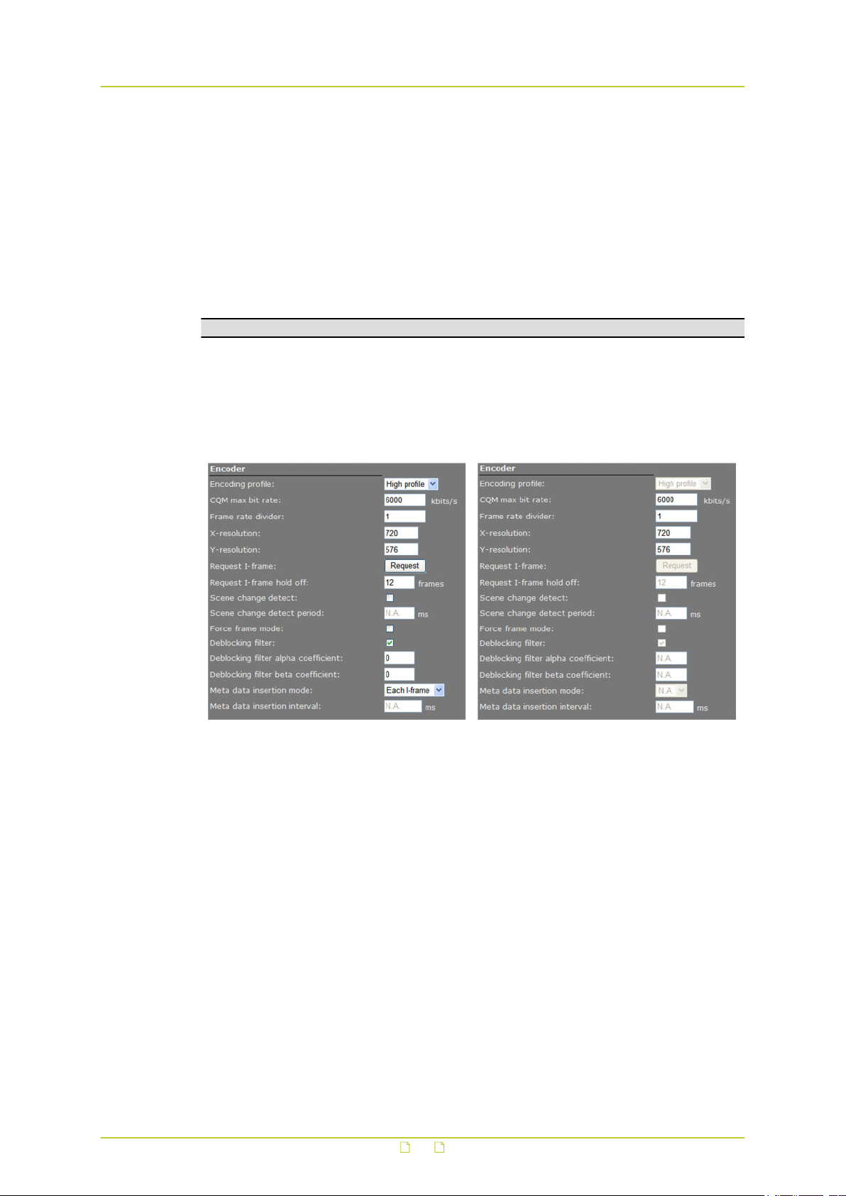
Video
SDP download
Use the SDP Download button to download a Session Description Protocol (SDP) file from the
encoder. SDP files contain streaming media initialisation parameters and properties. An SDP
file does not deliver media itself but through file association the media stream can be opened
in media players such as QuickTime and VLC. You can also use the SDP file to specify the URI
in your web browser.
11.3.4 Advanced
Important: If in doubt about these settings, do not change the default values.
11.3.4.1 Encoder
Depending on the selected encoding mode, specific parameter values in this section are
dimmed - that is, not available for configuration.
H.264 encoding, Constant Quality Mode MJPEG encoding, Constant Quality Mode
Video > Encoder 1/2 > Advanced Settings > Encoder
50
Page 51

Video
Item Description
Encoding profile Main profile Compatibility mode for decoders which do not
support High profile.
High profile Improved encoding quality (as compared to Main
profile).
CQM max bit rate Available in Constant quality mode (CQM). Use this setting to set the
maximum bit rate for a given picture quality configured in the Encoder
Settings section.
Frame rate divider Relates to the frame rate configured in the Encoder Settings section.
X-resolution Variables that enable you to freely set picture resolution instead of
Y-resolution
Request I-frame When joining a multicast stream in the middle of a long GOP,
Request I-frame
hold off
Scene change
detect
Scene change
detect period
Force frame mode If Force frame mode is enabled, the H.264 video stream is
Deblocking filter Enables the in-loop deblocking filter in the AVC encoder. H.264
Deblocking filter
alpha coefficient
Deblocking filter
beta coefficient
Meta data
insertion mode
Meta data
insertion interval
using the resolution presets in the Encoder Settings section.
requesting an I-frame will speed up response time, i.e. image display
will start sooner.
Range: [0…255] frames. Requesting (too) many I-frames may add to
latency. To prevent this, you can specify the distance in frames,
starting after the previous I-frame, before another I-frame is sent
upon request.
Enables the scene detection algorithm. If enabled, the encoder can
fully restart a new GOP with an I-slice and an instantaneous decoding
refresh (IDR) picture, depending on image content.
Sets the minimum time between scene changes in milliseconds. This
is a hold-off mechanism that prevents a scene change for the
specified time, starting from the previous scene change.
compressed and sent using entire frames (Frame mode). If disabled,
the stream is compressed and sent using entire frames or the
separate fields (Field mode).
encoding can handle portions of the video image in blocks of varying
sizes which can be processed independently. The deblocking filter
enhances image quality by smoothing block edges and reducing
blocking distortion. Be aware, however, that applying the filter
requires substantial processing power.
Set the alpha/beta coefficients of the deblocking filter. Entering
experimental values for these coefficients may help you in achieving
optimal image quality.
Determines the method used to add meta data to the stream. For
details, see the section on Meta Data Insertion.
Disabled No meta data added to the stream.
Fixed interval Activates Meta data insertion interval parameter.
Each I-frame Data block is added after each I-frame. The interval
is determined by the GOP length, therefore.
Range: [100-10000] ms. Sets the (fixed) interval at which meta data
is added to the stream. Activate this parameter by setting Meta data
insertion mode (see above) to Fixed interval.
51
Page 52

Video
11.3.4.2 Stream Manager
Video > Encoder # > Advanced > Stream Manager
Balancing network load
Peaks in the network load vary with encoder output. Use the Stream Manager to balance
network load. It can limit the output rate per stream sent to the transmitters. Be warned that
setting the Stream bandwidth limit to a lower value may introduce latency because peaks in
the encoder output will be buffered.
Item Description
Stream bandwidth
limit
Keep-alive interval Range: [10 … 100000] milliseconds. The frequency for sending
Low latency Raises the output bandwidth limit to allow for peaks in the network
Note on Low Latency mode: This mode may cause packet loss in the network. In this
mode, short bursts of 100 MB data may overflow the input buffer of an Ethernet aggregation
switch. As a rule of thumb, the average load of an Ethernet port should not exceed 40% of
its maximum load (i.e. 40 MB for a 100 MB port).
Range: [0...100000] kbit/s. Sets the maximum bit rate per stream
sent to the transmitters. This will serve to spread bursts but in its
turn may give rise to latency, e.g. when handling large I-frames.
You are advised to limit the outgoing bit rate per encoder to a
maximum of 15 Mbit/s. The total outgoing bit rate of all encoders
(including the Live View encoder), RTSP controlled streams, and
SAP streams, should not exceed 25 Mbit/s. See the value for the
Total tx bit rate parameter on the Measurements tab of the Status
page.
The Stream bandwidth limit mechanism is disabled when Low
latency (see below) is selected. See also the graphic in the Note on
FloodGuard.
keep-alive messages to the encoder.
load. To be selected if you need to keep the delay between the
input and output of images as short as possible, for improved
tracking with a dome camera for example. Selecting Low latency
disables the Stream bandwidth limit mechanism.
52
Page 53

Video
11.3.4.3 Transmitter #
Video > Encoder # > Advanced > Transmitter 1
Item Description
DSCP field Range: [0...63]. DSCP (Differentiated Services Code Point) uses the
Connection
priority
Multicast TTL Range: [0...127]. Specify the number of routers (hops) that multicast
RTP control mode Select the transport protocol to control the stream.
Stream type UDP + RTP Default setting. Plain RTP stream over UDP.
RTP type Default value: [0]. This parameter determines the RTP payload format
Link loss alarm
timeout
first 6 bits of the ToS (Type of Service) field in the header of IP
packets for packet classification purposes. The bit pattern in the field
indicates the type of service and forwarding behavior at the next node.
With 26 bits, up to 64 network service types can be defined. RFC 2724
(see - http://www.ietf.org/rfc/rfc2474.txt) describes the Differentiated
Services (DS) field and the DiffServ Code Point. See also the note on
Differentiated Services later in this chapter.
Parameter intended for use with MX Software Development Kit.
traffic is permitted to pass through before expiring on the network.
None No transport protocol selected.
FloodGuard Flooding prevention mechanism. For more
information, see the note on FloodGuard later
in this chapter.
RTCP Real-Time Control Protocol, a network control
protocol for use in communications systems to
control streaming media servers.
UDP + RTP + NKF Adds an extended RTP header for TKH
Security applications requiring extra
information.
(e.g. H.264, MPEG-2/4, or audio). To avoid an RTP type conflict, the
values specified on both sides of the connection must be the same.
The default value of "0" automatically sets the appropriate media type.
You are advised not to change this setting.
Range: [1...1000] s. Default: 10 s. Time in seconds before alarm sent.
53
Page 54
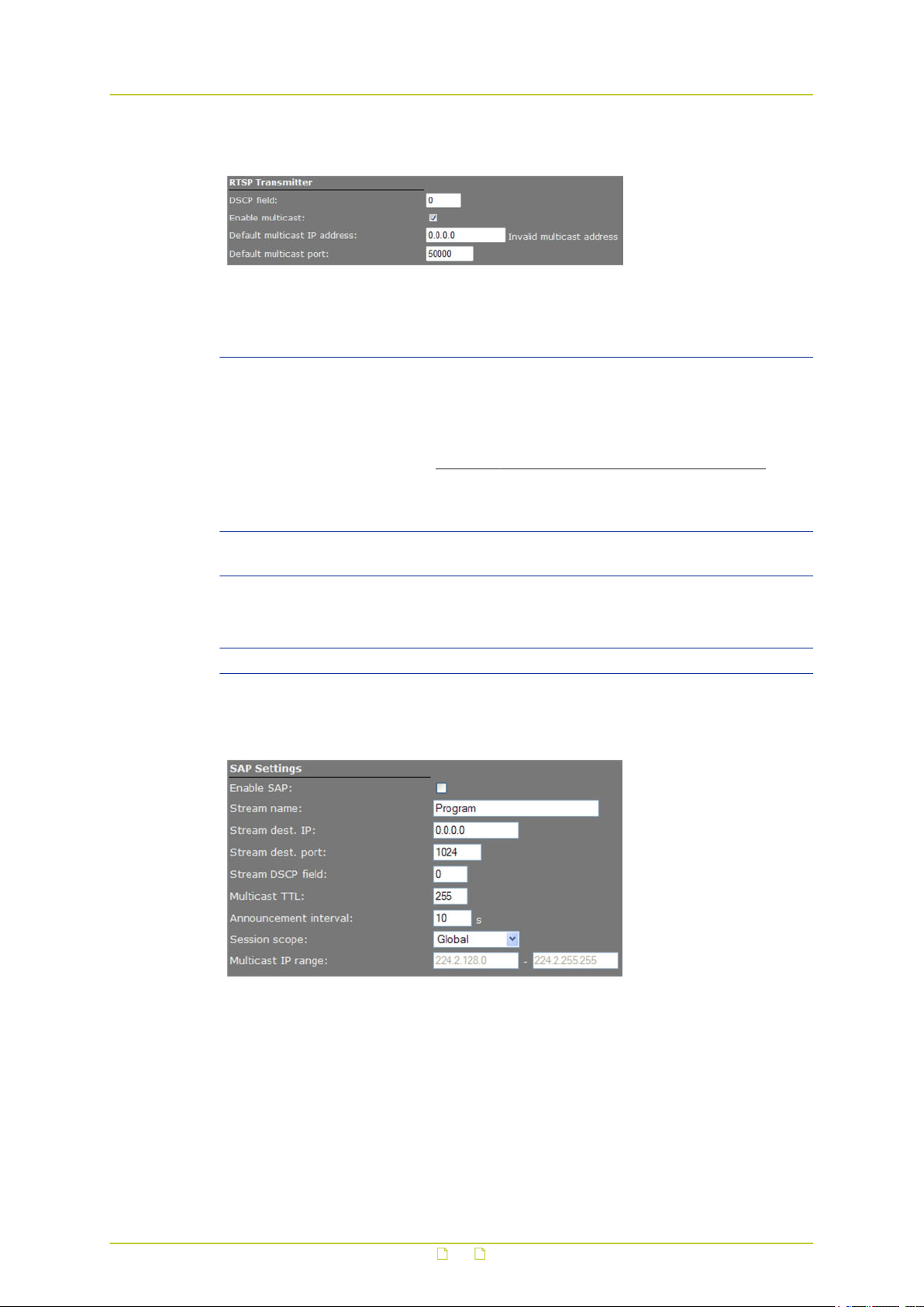
Video
11.3.4.4 RTSP Transmitter
Video > Encoder # > Advanced > RTSP Transmitter
Item Description
DSCP field Range: [0...63]. DSCP (Differentiated Services Code Point) uses
Enable multicast Activates the Default multicast IP address text box. The RTSP
Default multicast IP
address
Default multicast port Port number for multicast sessions.
the first 6 bits of the ToS (Type of Service) field in the header of IP
packets for packet classification purposes. The bit pattern in the
field indicates the type of service and forwarding behavior at the
next node. With 26 bits, up to 64 network service types can be
defined. RFC 2724 (see - http://www.ietf.org/rfc/rfc2474.txt)
describes the Differentiated Services (DS) field and the DiffServ
Code Point. See also the note on Differentiated Services later in
this chapter.
transmitter itself does not require enabling.
Select Enable multicast (see above) to activate this check box.
The "Invalid multicast address" warning disappears upon
specification of a valid multicast address.
11.3.4.5 SAP Settings
Video > Encoder # > Advanced > SAP Settings
SAP announcer
The BC840-MC includes a SAP announcer. The Session Announcement Protocol is used to
advertise that a media stream generated by the BC840-MC is available at a specific multicast
address and port.
54
Page 55

Video
The BC840-MC can send SAP multicast streams generated by its H.264 and audio encoders.
The video streams will include audio if audio is enabled on the Audio web page and if the
multicast IP range is the same as for video. Note that audio in itself can also be received as a
separate stream. For more information about SAP, see the note later in this chapter.
Item Description
Enable SAP When selected, session announcements are sent at the frequency
determined by the Announcement interval parameter and the
media stream is transmitted to the multicast IP address specified in
the Stream dest. IP address box.
Stream name Enter a descriptive name to identify the media stream.
Stream dest. IP Enter the multicast IP address the media stream is to be sent to.
The address must be within the range defined by the Multicast IP
range parameter.
Stream dest. port The destination port number. Default: 1024.
Stream DSCP field Range: [0…63]. See the note on DSCP.
Multicast TTL Range: [0...127]. Specify the number of routers (hops) that
multicast traffic is permitted to pass through before expiring on the
network.
Announcement
interval
Session scope Global, the default session scope, sets the Multicast IP range
Multicast IP range See Session scope.
Determines the frequency of announcements.
parameter to 224.2.128.0 - 224.2.255.255 (IPv4 global scope
sessions). A SAP listening application will recognize the global
scope and automatically listen for SAP announcements at the
224.2.127.254 multicast IP address.
The Administrative session scope allows you to enter a custom IP
range within the 239.0.0.0 - 239.255.255.255 (IPv4 administrative
scope sessions) range. For an Administrative session scope, the
multicast address for SAP announcements will be set to the highest
address in the relevant administrative scope. For example, for a
scope range of 239.16.32.0 - 239.16.33.255, the IP address
239.16.33.255 is used for SAP announcements.
To configure SAP settings, do the following
1 In the SAP settings section, select Enable SAP.
2 Enter a stream name.
3 In the Session scope list, select Global or Administrative.
4 If you selected Administrative in the previous step, specify the Multicast IP range.
5 Enter the Stream Destination IP address and the port number.
The IP address must be within the scope range displayed for the Multicast IP range
parameter.
6 Enter/modify the values for Stream DSCP field, Multicast TTL, and Announcement
Interval, if desired.
7 Click Save.
The video stream can now be viewed in a media player, such as QuickTime or VLC.
55
Page 56
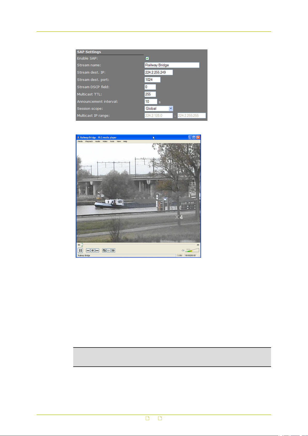
Video
SAP example settings
BC840-MC SAP network stream opened via VLC Playlist
11.3.5 Meta data insertion
Enabling
All BC840-MC encoders can be configured to include meta data in the video streams they
generate. The insertion of meta data is enabled by setting an interval via the Advanced
Settings of the encoder. A meta data message is added to the stream as a block of data with
a fixed format (see examples below). The messages can contain user data, product info, and
status info.
Note: This section provides a general explanation of meta data insertion as implemented in
TKH Security products. The unit described in this manual, may or may not feature all of the
media (e.g. audio, contact closure) and encoding formats included below.
User data message
For MPEG-2 and MPEG-4, User data is preceded by the User data header (00 00 01 B2):
56
Page 57

Video
0x00 0x00 0x01 0xB2 User data message
For MJPEG, these (for the rest identical) messages are inserted as comment field (FF FE):
0xFF 0xFE
For H.264, these (for the rest identical) messages are inserted as SEI NAL-unit (0x06),
marked as type User Data Unregistered (0x05):
0x06 0x05 Size UUID (16 bytes) User data message
Size
(MSB)
Size (LSB) User data message
Product info message
The Product info message (always inserted) is used to identify the source of a specific video
stream. The data ID is 0x00, with the message in the following layout.
Serial
nr
(ASCII)
0x80
SW version
(ASCII)
0x80
'O' 'P' 'T' 'C' 0x00
Prod. name
(ASCII)
0x80
Status info message
This message contains all relevant status messages, related to the video stream or codec. The
data ID is 0x01, with the message in the following layout.
(future
'O' 'P' 'T' 'C' 0x01 Status1 Status2 Status3 Status4
expansion
possible)
Status 1 Video status
Bit 0 (lsb) Video loss on input
Bit 1 Black/white video
Bit 2 VMD alarm
Bit 3 Tampering alarm
Bit 4 Image quality alarm
Bit 5 (for future use, will be ‘0’)
Bit 6 (for future use, will be ‘0’)
Bit 7 (msb) Fixed ‘0’
57
Page 58

Video
Status 2 General status
Bit 0 Reserved for Temperature alarm
Bit 1 (for future use, will be ‘0’)
Bit 2 (for future use, will be ‘0’)
Bit 3 (for future use, will be ‘0’)
Bit 4 (for future use, will be ‘0’)
Bit 5 Reserved for Audio present
Bit 6 Fixed ‘1’
Bit 7 Fixed ‘0’
Status 3 CC status (part 1)
Bit 0 CCin-1
Bit 1 CCin-2
Bit 2 CCin-3
Bit 3 CCin-4
Bit 4 CCin-5
Bit 5 CCin-6
Bit 6 CCin-7
Bit 7 Fixed ‘0’
Status 4 CC status (part 2)
Bit 0 CCin-8
Bit 1 (for future use, will be ‘0’)
Bit 2 (for future use, will be ‘0’)
Bit 3 (for future use, will be ‘0’)
Bit 4 (for future use, will be ‘0’)
Bit 5 (for future use, will be ‘0’)
Bit 6 Fixed ‘1’
Bit 7 Fixed ‘0’
User defined text message
This message can be defined and enabled by the user, using the SPI API, for example. There
is no maximum limit on the amount of characters. Considering that this data is part of a video
stream, the maximum should be reasonable.
58
Page 59

Video
11.3.6 Notes
Note on Differentiated Services: Differentiated Services (DiffServ, or DS) is a method for
adding QoS (Quality of Service) to IP networks. In routed networks, critical network traffic
such as video and audio streams, which require a relatively uninterrupted flow of data, can
get blocked due to other traffic. DiffServ can be used to classify network traffic and give
precedence - i.e. low-latency, guaranteed service - to high-priority traffic, while offering
best-effort service to non-critical traffic such as file transfers or web traffic.
Each stream has a DSCP (Differentiated Services Code Point) field in the IP header. Routers
will identify the network service type in the DSCP field and provide the appropriate level of
service. Low-latency service can be realized, for example, through priority queuing,
bandwidth allocation, or by assigning dedicated routes.
Note on RTP and RTCP: The Real-time Transport Protocol (RTP) is designed for end-to-end
real-time, audio or video data flow transport. It is regarded as the primary standard for
video/audio transport over multicast or unicast network services. RTP does not provide
guaranteed delivery, but sequencing of the data makes it possible to detect missing packets.
It allows the recipient to compensate for breaks in sequence that may occur during the
transfer on an IP network. Error concealment can make the loss of packets unnoticeable.
RTP is usually used in conjunction with the Real-time Transport Control Protocol (RTCP). RTP
carries the media streams. RTCP provides reception quality feedback, participant
identification and synchronization between media streams.
Note on the Session Announcement Protocol (SAP): SAP, defined in RFC 2974 (see RFC
2974 - http://www.ietf.org/rfc/rfc2974.txt), is a protocol for advertising multicast session
information. A SAP announcer periodically broadcasts announcement packets which include
the session description information of multicast sessions presented by the announcer. SAP
uses the Session Description Protocol (SDP) as the format of the session descriptions. The
announcement is multicast with the same scope as the session it is announcing, ensuring
that the recipients of the announcement are within the scope of the session the
announcement describes. SAP listening applications can listen to the announcements and
use the information to construct a guide of all advertised sessions. This guide can be used to
select and start a particular session. The SAP announcer is not aware of the presence or
absence of SAP listeners.
Note on FloodGuard: FloodGuard is a TKH Security proprietary stream control mechanism
that can be enabled/disabled independently for each video and sampled data transmitter.
FloodGuard throttles the transmitter when it no longer receives control messages from the
receiver, thereby preventing the transmitter from flooding the network.
FloodGuard only works when enabled on both the transmitter and the receiver, and when
the transmitter sends to a unicast address.
When a transmitter is enabled, it opens a control receive port with the port number equal to
its source port number + 1. This port listens for control packets from the destination
receiver. When no FloodGuard packets come in during the time set for the FloodGuard
throttle delay, the receiver is expected to have disappeared (powered off, receiver disabled,
network problem, etc.) and the stream is 'throttled'. In throttled mode the transmitter - in
order to contact the intended receiver (again) - sends empty packets into the network at an
interval determined by the FloodGuard throttle interval parameter. After reception of a valid
FloodGuard packet the transmitter immediately resumes streaming.
59
Page 60
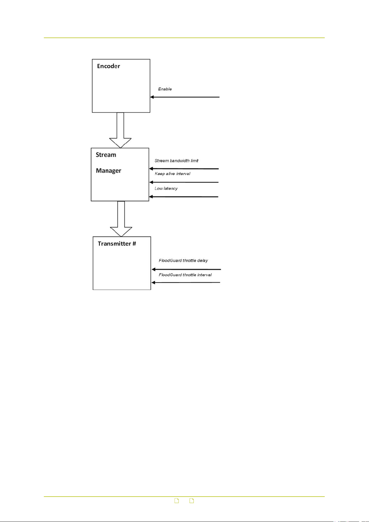
Video
Stream Manager and FloodGuard
60
Page 61
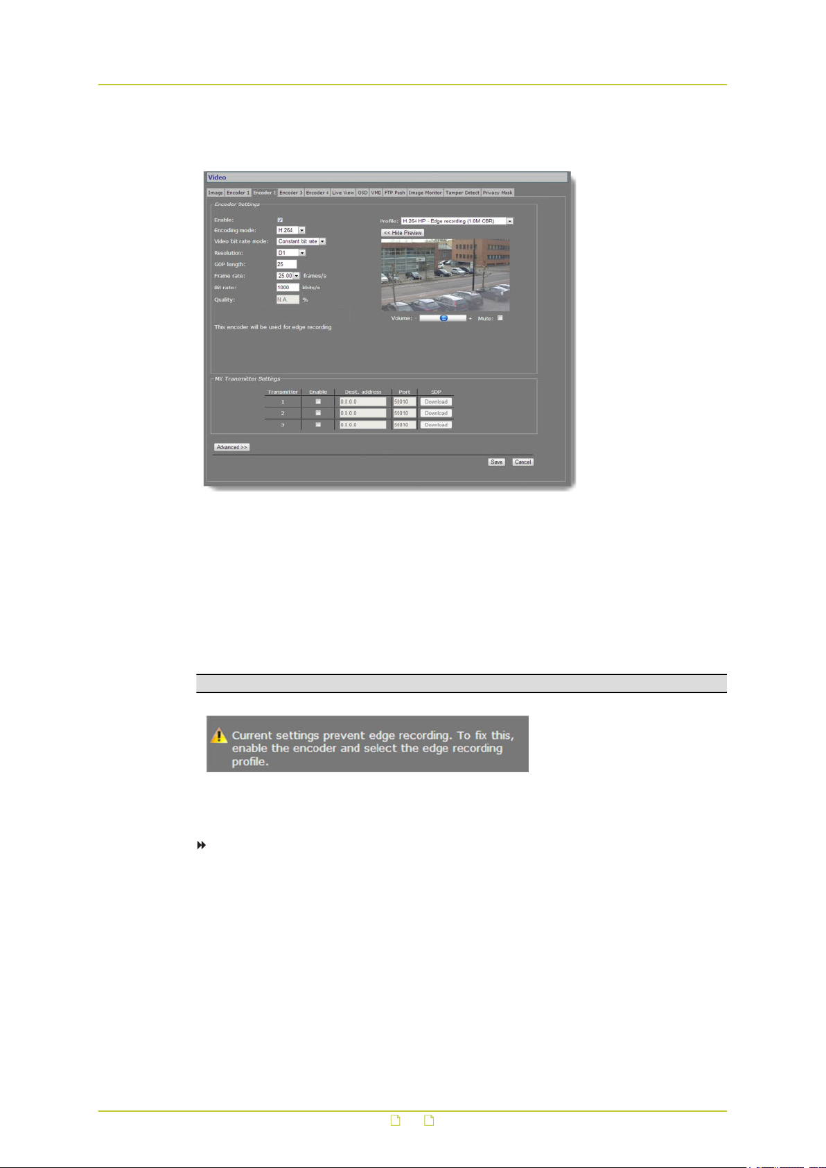
Video
11.4 Encoder 2
Video > Encoder 2
11.4.1 Edge recording
Configuring Encoder 2 settings is done in the same way as for Encoder 1. It is important to
bear in mind, however, that edge recording uses video generated by Encoder 2 and that this
requires specific Video bit rate, GOP length, and Bit rate settings.
Important: If you change these settings, edge recording may become impossible.
Warning: Incorrect encoder settings for edge recording
To configure settings for edge recording
1 Select Enable to enable the encoder.
2 On the Profile list, select H.264 - Edge recording (1.0M CBR).
3 Click Save.
This creates the following settings.
- Encoding mode: H.264
- Video bit rate mode: Constant bit rate
- GOP length: 25
- Bit rate: 1000 kbit/s
61
Page 62
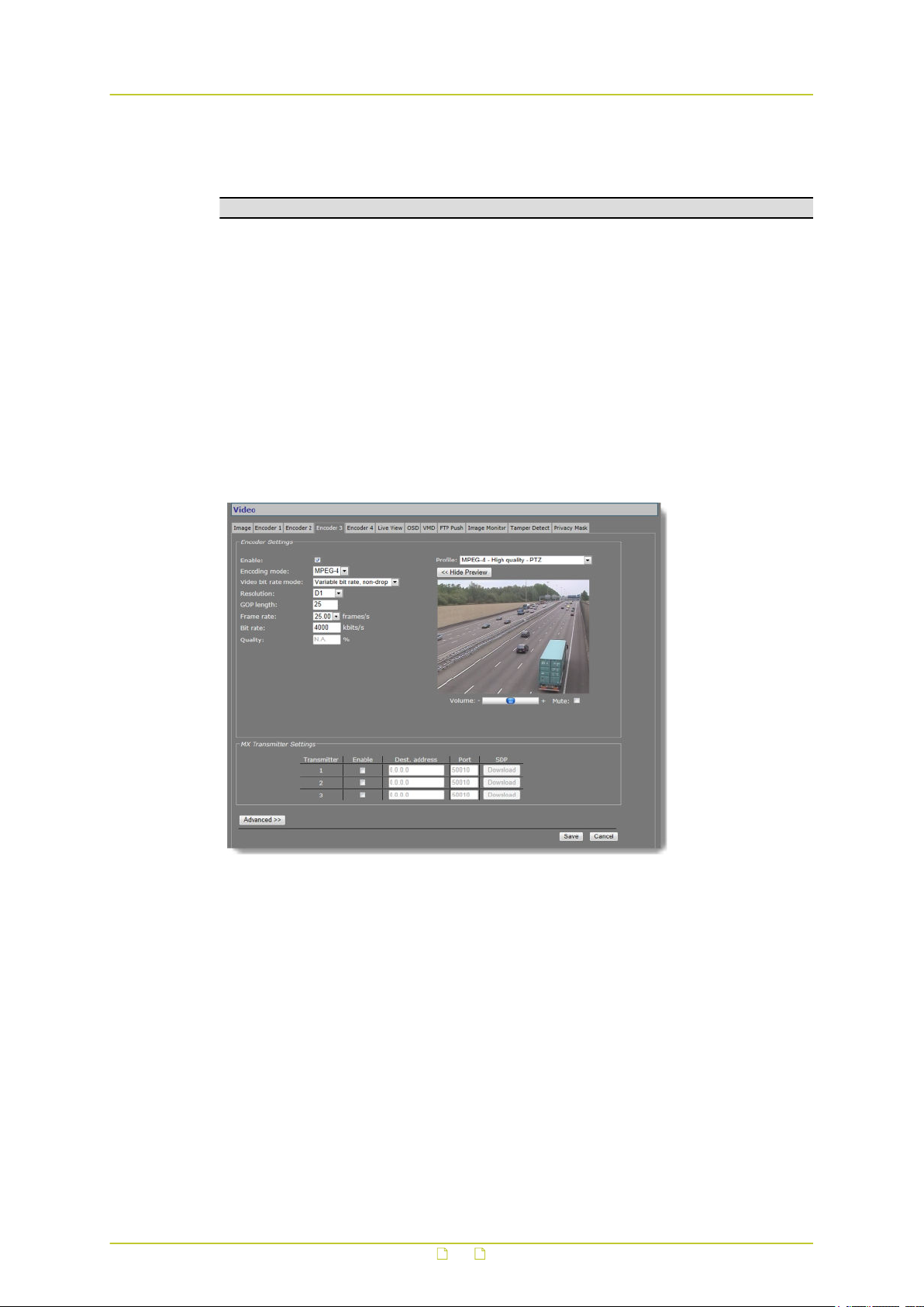
Video
These settings are also the out-of-the box, factory-default settings for Encoder 2. If they are
no longer correct just select the H.264 - Edge recording (1.0M CBR) profile to restore the
proper settings.
Note: For best results, we recommend to use CIF resolution for edge recording.
Custom settings
If you need to apply custom settings, you can do so with the following restrictions.
● Encoding mode: always set to H.264
● Video bit rate mode: always set to Constant bit rate
● GOP length: ≥ 25
● Bit rate: ≤ 1000 kbit/s
● Resolution: CIF (recommended)
11.5 Encoder 3/4
Video > Encoder 3
62
Page 63
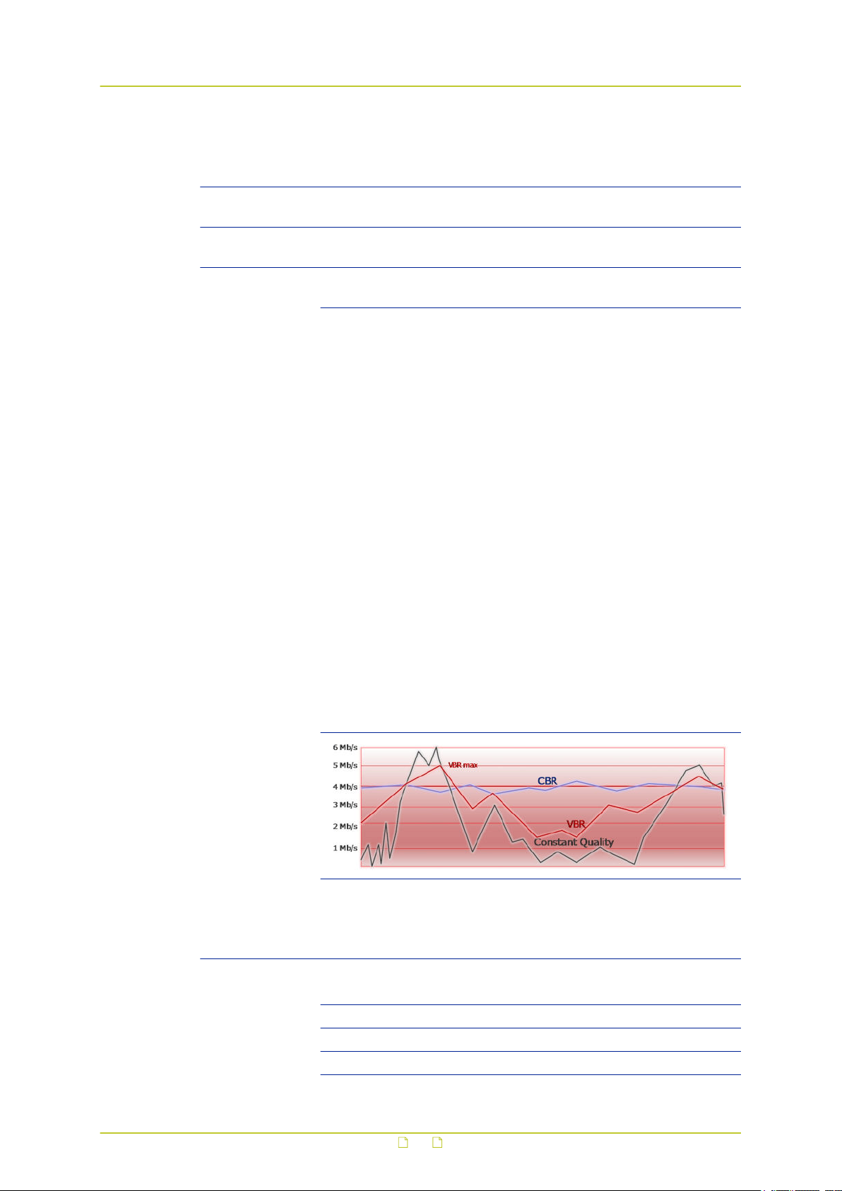
Video
11.5.1 Encoder Settings
Item Description
Enable All encoders are enabled by default. Use this check box to disable/re-
Encoding mode MPEG-4 or MPEG-2 The method used to compress the video
Video bit rate
mode
enable this specific encoder.
signal.
Controls variations in bit rates. For a concise explanation, consult the
note on Encoder Settings later in this chapter..
MPEG-4 encoding mode supports the following bit rate modes.
Constant quality Keeps the image quality constant, with
varying network load (from a few kb/s to 10
Mb/s or higher). The image quality is
determined by the values set for the “Q min I”
and “Q min P” parameters in the Advanced
Settings section.
Variable bit rate Variable network load, but limited to value set
for the VBR maximum bit rate parameter in
the Advanced Settings section. The frame rate
will suffer when the VBR maximum bit rate is
reached.
Variable bit rate, nondrop
Constant bit rate Keeps network load constant at the cost of
Constant bit rate,
non-drop
Variable network load, but limited to value set
for the VBR maximum bit rate parameter in
the Advanced Settings section. The quality will
decrease when the VBR maximum bit rate is
reached. The frame rate will be constant.
varying image quality. Frames may be
skipped.
Keeps network load constant at the cost of
varying image quality. Frames are never
skipped.
MPEG-2 encoding mode supports the following bit rate mode.
Constant bit rate,
non-drop
Resolution The following resolutions are supported.
resolution (h x v) PAL NTSC
D1 720x576 720x480
2/3 D1 480x576 480x480
1/2 D1 352x576 352x480
63
Keeps network load constant at the cost of
varying image quality. Frames are never
skipped.
Page 64

Video
Item Description
4CIF 704x576 704x480
2CIF 720x288 720x240
CIF (top field only) 352x288 352x240
QCIF 176x144 176x120
In addition, VGA (640x480) and QVGA (320x240) are also supported.
For more information on CIF resolutions, see "Notes" later in this
chapter.
Note: The BC840-MC will simultaneously handle dual H.264 encoding
and dual MPEG-2/4 encoding at full frame rate, and Live View
encoding at 5 frames per second. Setting Encoders 3 and 4 to
perform MPEG-2/4 encoding in D1 resolution at the same time may
overtax the hardware. The total output bandwidth, including streams
controlled by RTSP, and those enabled through SAP, should not
exceed 25 Mb/s.
GOP length Distance in frames between two I-frames.
Frame rate PAL: 1-25 fps; NTSC: 1-30 fps. Selectable rates are determined by the
video mode (PAL, NTSC) set on the Image tab.
Bit rate Range: [10…15000]. Selecting a profile (see below), automatically sets
the bit rate associated with the profile.
Profile Preset combinations of settings for specific purposes. When a profile
has been selected, changing one of its defined parameters sets the
Profile box to '--', to indicate that a custom profile has been
configured. When a freely chosen parameter value combination
matches a preset profile, the name of the profile shows in the Profile
box.
Show Preview>> Click to view live images and see the effect of the current settings.
<<Hide Preview Closes the preview. This may improve webpage responsiveness.
Volume Move the slider to control audio volume.
Mute Select/clear this box to mute/unmute audio.
11.5.1.1 Combinations of settings
Set sensible combinations of video bit rate mode, resolution, GOP length, and frame and bit
rates. When setting and saving these values, you may notice that inappropriate value
combinations are ‘corrected’ by automatic selection of the closest suitable combination. The
output bit rate set may range from 10-15000 kbps. The total output bandwidth should not
exceed 25 Mb/s.
64
Page 65

Video
11.5.1.2 Note
Note on Encoder Settings: Video bit rate mode can be set to be constant (i.e. the number
of bits in a group of pictures) or variable. Selecting the correct mode for a given application,
with emphasis on a good compromise between detail and good representation of frequent
changes (motion), is generally vital.
Constant bit rate mode (CBR) is generally safest. Although the image quality may vary, the
network load generated will remain fairly constant.
If constant picture quality is required and a varying network load will pose no problems,
choose Variable bit rate mode (VBR). Video streaming is generally smoother under VBR.
Improving video picture quality and video stream quality, in terms of latency and
smoothness for example, is subject to trade-offs. Many aspects of picture quality and stream
quality are governed by a series of compression and signal parameters which may work
favorably on one aspect while adversely affecting another.
For example, increasing the bit rate generally improves video quality, but also puts
additional load on the network. But even for a given bit rate and network performance, video
quality and streaming are influenced by other parameters and aspects. Please consult
appropriate literature on video encoding formats, and application notes for clarification.
If in doubt about the effects of specific encoder settings, you are advised to select the profile
offering the closest match to your required application.
11.5.2 Make a video connection
Creating a video link between Encoder 3/4 and a video decoder is done in the same fashion as
described for Encoder 1/2 earlier in this chapter.
11.5.3 Advanced
Important: If in doubt about these settings, do not change the default values.
11.5.3.1 Encoder
Depending on the selected encoding mode, specific parameter values in this section are
dimmed - that is, not available for configuration.
MPEG-2 mode
Video > Encoder # > Advanced > Encoder (MPEG-2 mode)
65
Page 66

Video
Item Description
Frame rate divider Relates to the frame rate configured in the Encoder Settings
section.
X-resolution Variables that enable you to freely set picture resolution instead of
Y-resolution
Stream type Transport Stream or Elementary Stream.
Quantization matrix MPEG Default, Alternative 1, or Alternative 2.
Meta data insertion
mode
Meta data insertion
interval
using the resolution presets in the Encoder Settings section.
For details, see the section on Meta Data Insertion.
Disabled No meta data added to stream.
Fixed interval Activates Meta data insertion interval
parameter (below).
Each I-frame Data block is added after each I-frame. The
interval is determined by the GOP length,
therefore.
Activate this parameter by setting Meta data insertion mode
(above) to Fixed interval.
Note on Quantization: Quantization is a lossy compression technique used in image
processing. It is based on the fact that variations in high frequency brightness, for example,
are not easily distinguished by the human eye. A quantization matrix, a combination of
predefined values, is used to reduce the amount of information in the high frequency
components of an image, thereby making the stream more compressible. The values in a
quantization matrix are often chosen such that certain frequencies are kept in the source to
avoid losing image quality.
MPEG-4 mode
Video > Encoder # > Advanced > Encoder (MPEG-4 mode)
66
Page 67

Video
Item Description
VBR maximum
bit rate
Q min I Used to achieve consistent picture quality within a single GOP or across
Q min P
Frame rate
divider
X-resolution Variables that enable you to freely set picture resolution instead of using
Y-resolution
Request Iframe
Request Iframe hold off
Meta data
insertion mode
Meta data
insertion
interval
Range: [0...15000]. Sets a limit for variable bit rate.
consecutive GOPs. Lower values produce a better picture, but will yield
higher bit rates and require more processing. Default Q min I = 3; default
Q min P = 2.
Relates to the frame rate configured in the Encoder Settings section.
the resolution presets in the Encoder Settings section.
When joining a multicast stream in the middle of a long GOP, requesting
an I-frame will speed up response time, i.e. image display will start
sooner.
Range: [0…255] frames. Requesting (too) many I-frames may add to
latency. To prevent this, you can specify the distance in frames, starting
after the previous I-frame, before another I-frame is sent upon request.
For details, see the section on Meta Data Insertion.
Disabled No meta data added to stream.
Fixed interval Not supported for MPEG-4 streams. If
a fixed interval is set, the nearest Iframe will be used.
Each I-frame Data block is added after each I-frame.
The interval is determined by the GOP
length, therefore.
Activate this parameter by setting Meta data insertion mode (above) to
Fixed interval.
11.5.3.2 Stream Manager, Transmitter #, RTSP Transmitter, and SAP settings
Configuring Stream Manager, Transmitter #, RTSP Transmitter, and SAP settings for
MPEG-2/4 encoding is done in the same way as for Encoders 1/2. For details, see the
description earlier in this chapter.
67
Page 68
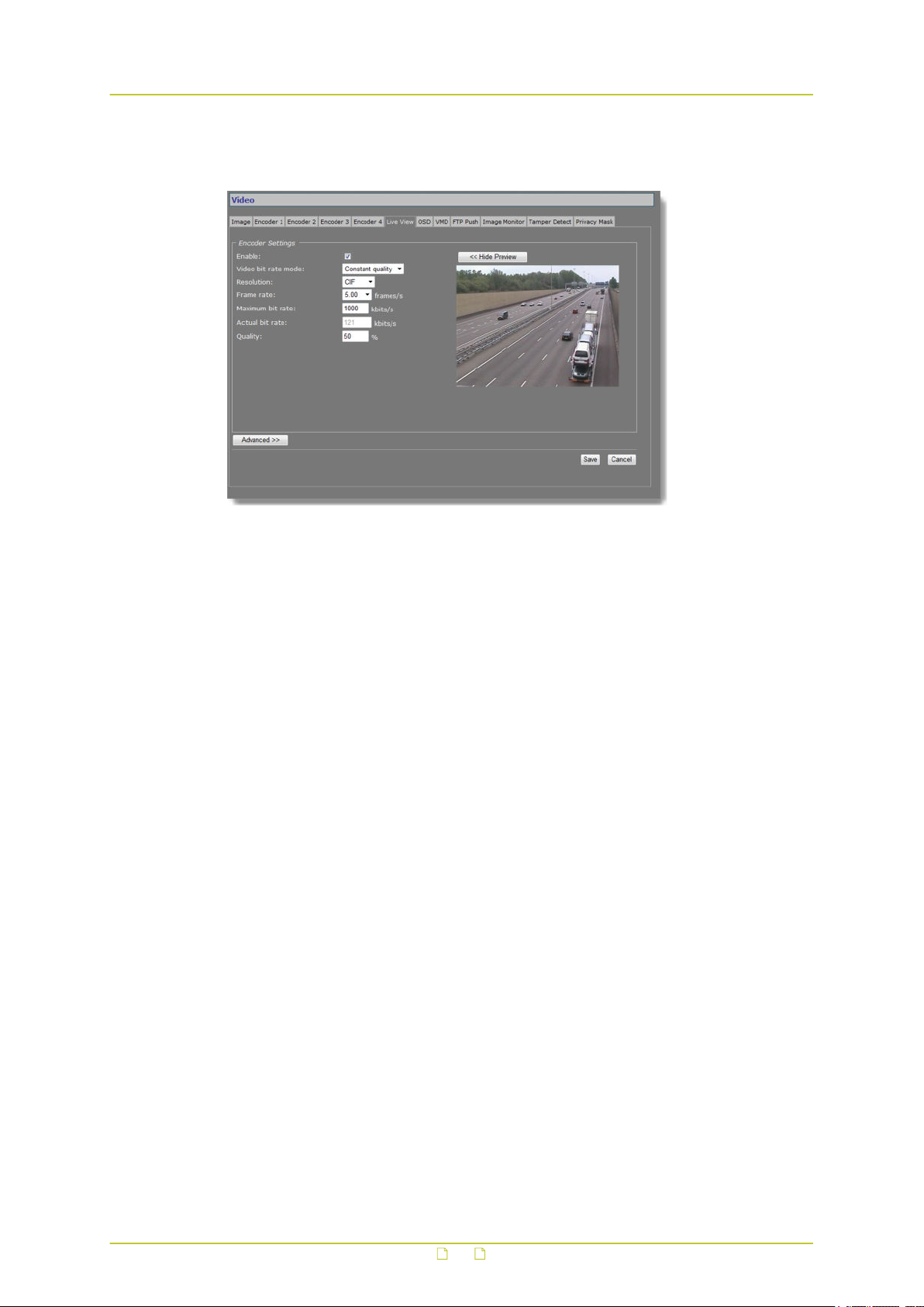
Video
11.6 Live View
Video > Live View
11.6.1 (M)JPEG output
The BC840-MC provides multiple (M)JPEG output methods.
● To transport JPEG over HTTP and/or to use the Live View previews in the webpages,
enable the Live View encoder and configure its settings.
● To enable and configure UDP/MJPEG streaming, go to the Encoder 1/2 tab, select MJPEG
encoding mode and configure settings.
● To activate the uploading of JPEG images to an FTP server, configure the required settings
on the FTP Push tab and the Event Management page.
68
Page 69

Video
11.6.2 Encoder Settings
Item Description
Enable All encoders are enabled by default. Use this check box to disable/re-
Video bit rate
mode
Resolution Set sensible combinations of mode, resolution, frame rate and
Frame rate
(Maximum) bit
rate
Actual bit rate Constant
Quality Constant
Show Preview>> Click to view live images and see the effect of the current settings.
<<Hide Preview Closes the preview. This may improve webpage responsiveness.
enable this specific encoder.
Controls variations in bit rates.
Constant
quality
Constant bit
rate
(maximum) bit rate. It is advised to limit MJPEG encoding to 5 fps
when the BC840-MC is also handling MPEG-2/4 encoding with 1xD1
and 1xCIF or 2CIF at full frame rate.
Quality Mode
(CQM) only
Quality Mode
(CQM) only
Keeps the image quality constant, with varying
network load. The quality is determined by the value
set for the Quality parameter (see below).
Keeps network load constant at the cost of varying
image quality. Frames may be skipped.
This field is dynamically updated with the current bit
rate to provide feedback on the bit rate that is used
on average with the current Quality setting.
Reflects the amount of compression. Generally
speaking: the higher the quality setting, the lower
the compression ratio and the more bits are
consumed. This means a trade-off has to be found
between the desired quality level and available
bandwidth.
11.6.3 Advanced
Video > Live View > Advanced
69
Page 70
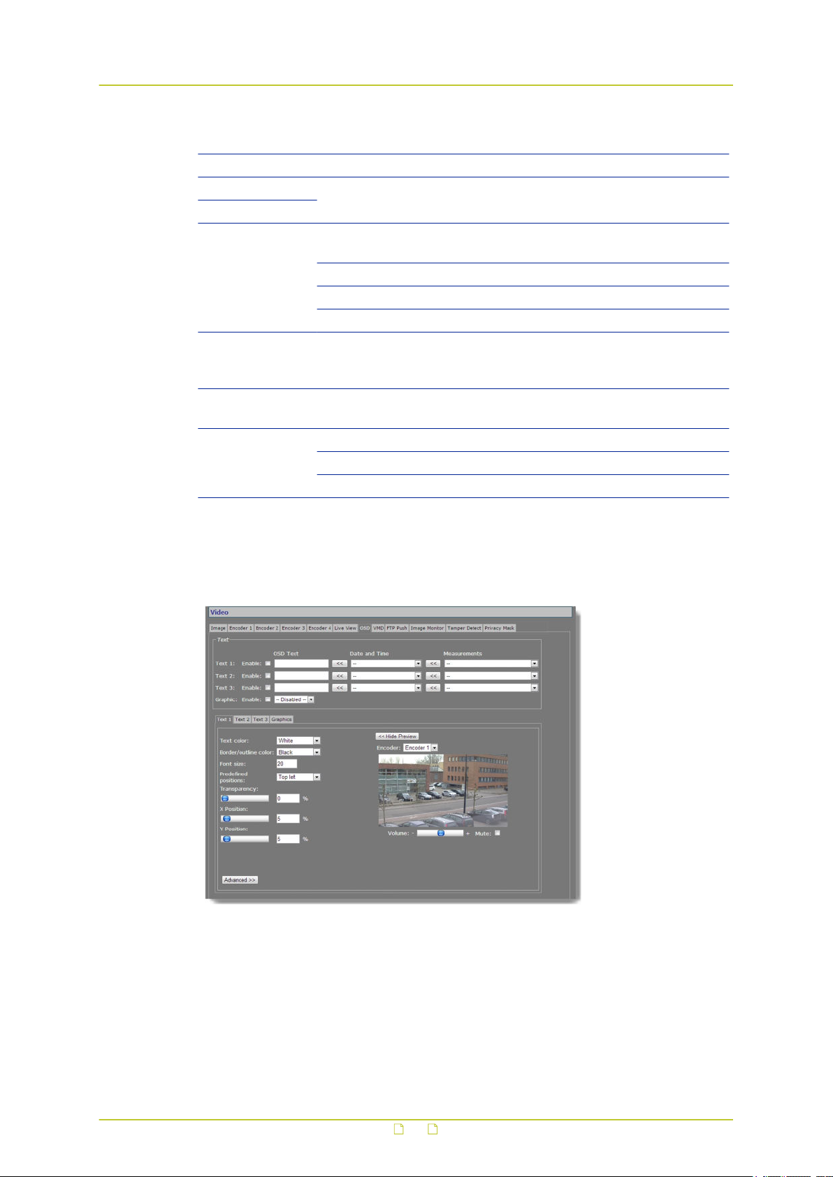
Video
Item Description
Frame rate divider Relates to the frame rate configured in the Encoder Settings section.
X-resolution Variables that enable you to freely set picture resolution instead of
Y-resolution
Meta data
insertion mode
Meta data
insertion interval
Enable HD
snapshot
Resolution Indicates the image size of the HD snapshot image (width x height).
using the resolution presets in the Encoder Settings section.
Determines the method used to add meta data to the stream. For
details, see the section on Meta Data Insertion.
Disabled No meta data added to the stream.
Fixed interval Activates Meta data insertion interval parameter.
Each frame Data block is added after each frame.
Range: [100-10000] ms. Sets the (fixed) interval at which meta data
is added to the stream. Activate this parameter by setting Meta data
insertion mode (see above) to Fixed interval.
Select this check box if you want to enable the possibility to retrieve
HD JPEG snapshot images using the URL http://<ip>/hdvideo.jpg
HD1080 1080p (1920x1080)
HD720 720p (1280x720)
11.7 OSD
Video > OSD
11.7.1 OSD facilities
The BC840-MC features programmable on-screen display (OSD) facilities. One graphic and up
to three OSD text bars can be displayed, each of which can be independently configured.
Visual feedback is provided in the preview.
70
Page 71
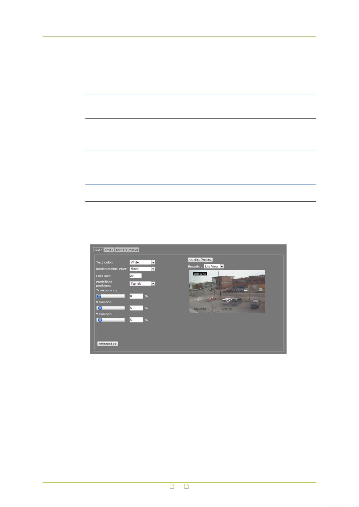
Video
11.7.2 Text Settings
Item Description
Enable All OSD objects can be enabled and configured separately. To
OSD text The text to be displayed. Maximum: 255 characters. Text is
Date and Time Select a format from the list and click the Append button to add
Measurements Select a measurement from the list and click the Append button to
Graphic Graphics that have been uploaded to the module (see Graphics tab,
(temporarily) remove a bar or graphic from the screen, clear the
Enable check box.
displayed in a single line. The number of characters visible on
screen is determined by the font size and the space offered by the
screen line.
the information to the OSD text box.
add the information to the OSD text box.
Advanced settings) can be selected from the list and enabled.
11.7.3 Text #
Video > OSD >Text 1, with 3 OSD bars in the preview.
Render modes: 'Border' (top left) and 'Outline' (bottom right & bottom centre)
71
Page 72
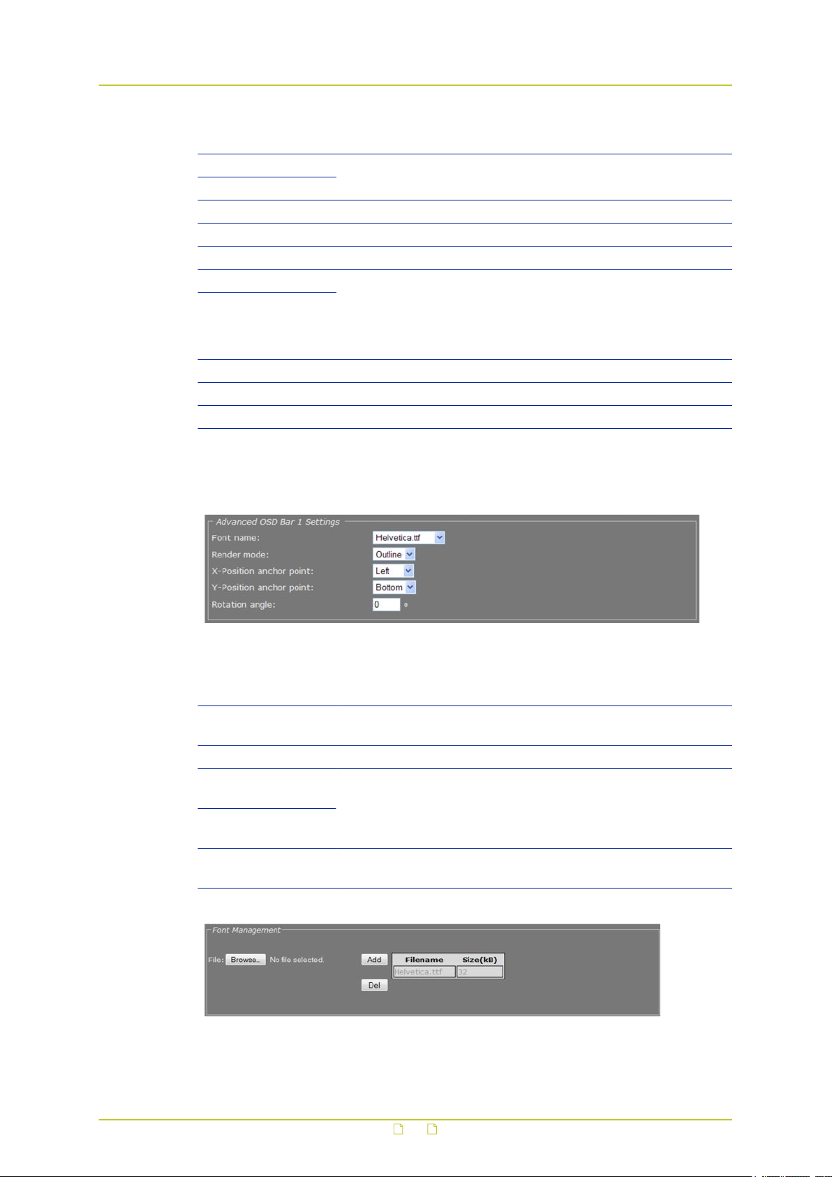
Video
Item Description
Text color Changes made here and in the other fields are immediately written
Border/outline color
Font size Range: [0...256].
Predefined positions Presets for positioning the OSD object.
Transparency Move the slider or type a percentage.
X Position Variables that enable you to freely position the object, instead of
Y Position
Show Preview>> Click to view live images and see the effect of the current settings.
<<Hide Preview Closes the preview. This may improve webpage responsiveness.
Encoder The encoder handling the images seen in the preview.
11.7.3.1 Advanced
into the device and reflected in the preview.
using the presets. Drag the sliding buttons or enter a percentage.
When a preset has been selected, changing one of its defined
parameters sets the Predefined positions box to ‘--’, indicating that
a custom position has been configured.
Video > OSD > Text 1 > Advanced > Advanced OSD Bar 1 Settings
Item Description
Font name Offers a selection from default and uploaded fonts (see Font
Management).
Render mode Outline or Border.
X-Position anchor
point
Y-Position anchor
point
Rotation angle Background size automatically adjusts to text dimensions when a
Video > OSD > Text 1 > Advanced > Font Management
Variables that enable you to shift the OSD object relative to the
anchor point.
bar is rotated.
72
Page 73
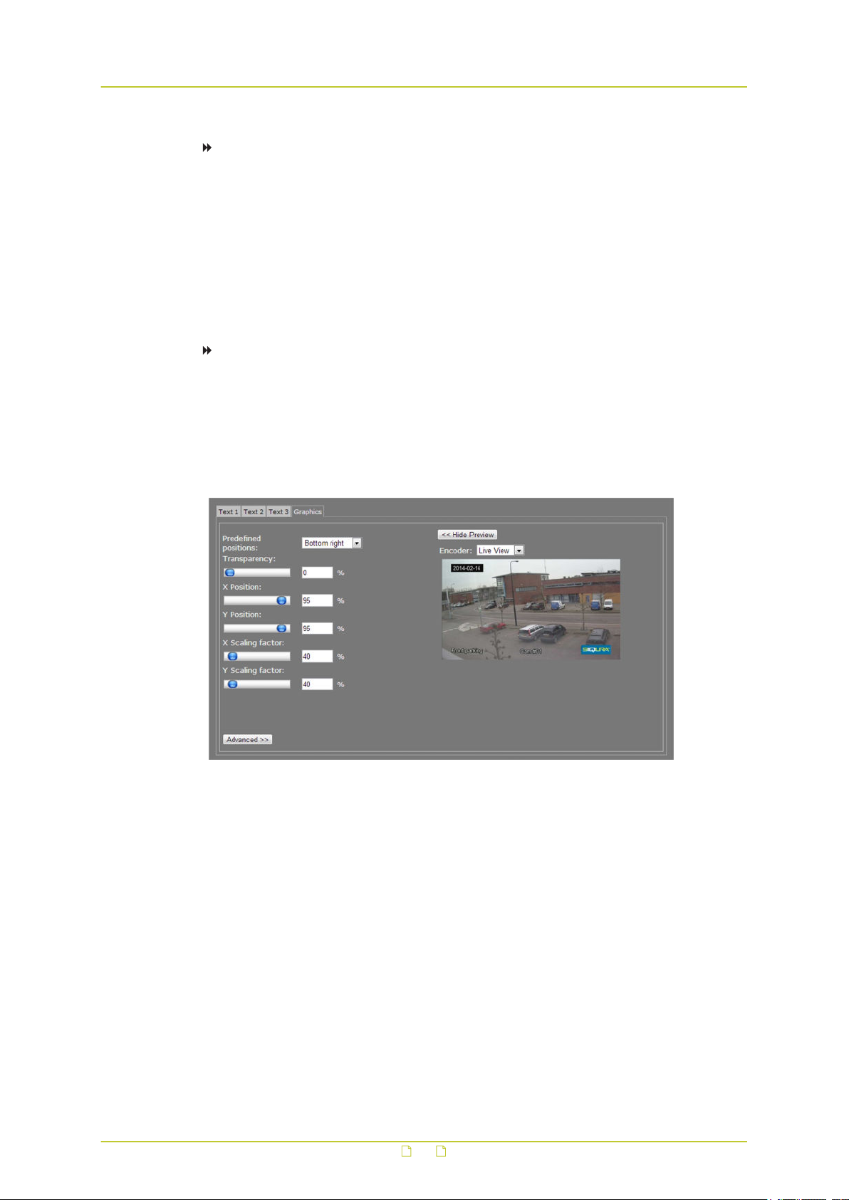
Video
To upload a font
1 In the Font management section, click Browse.
The Open dialog box displays.
2 Browse to the folder containing the font to be uploaded.
3 Select the correct file (.ttf extension), and then click Open.
The file appears in the File text box on the web page.
4 To start the upload, click Add.
The new font is added to the Font list and to the Font name list in the Advanced OSD
Bar # Settings section.
To remove a font
1 In the Font management section, select the font.
2 Click the Del button.
11.7.4 Graphics
Video > OSD > Graphics, with 3 OSD bars and a graphic (bottom right) in the preview
The Graphics tab enables you to manage graphics, and scale and position a selected graphic
on your screen.
73
Page 74
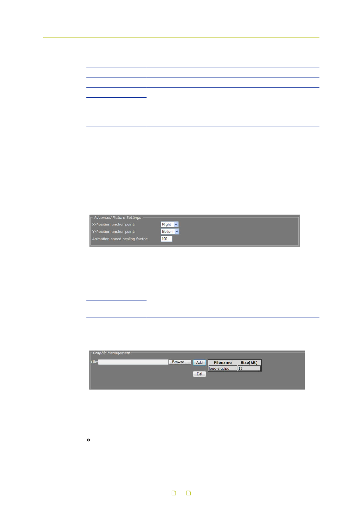
Video
Item Description
Predefined positions Presets for positioning the OSD object.
Transparency Move the slider or type a percentage.
X-Position Variables that enable you to freely position the object, instead of
Y-Position
X Scaling factor Variables that enable you to freely configure the dimensions of the
Y Scaling factor
Show Preview>> Click to view live images and see the effect of the current settings.
<<Hide Preview Closes the preview. This may improve webpage responsiveness.
Encoder The encoder handling the images seen in the preview.
11.7.4.1 Advanced
using the presets. Drag the sliding buttons or enter a percentage.
When a preset has been selected, changing one of its defined
parameters sets the Predefined positions box to ‘--’, indicating that
a custom position has been configured.
object.
Video > OSD > Graphics > Advanced > Advanced Picture Settings
Item Description
X-Position anchor
point
Y-Position anchor
point
Animation speed
scaling factor
Video > OSD > Graphics > Advanced > Graphic Management
You can upload your own graphics with a maximum file size of 100 kB to the BC840-MC. If
necessary, use a picture resize tool to reduce the file size.
Variables that enable you to shift the OSD object relative to the
anchor point.
Enables you to set the speed for an animated GIF graphic.
To upload a graphic
1 In the Graphic Management section, click Browse.
The Open dialog box displays.
74
Page 75

Video
2 Browse to the folder containing the graphic to be uploaded.
3 Select a file with the correct file extension (.bmp, .gif, .jpg, jpeg), and then click Open.
The file appears in the File textbox.
4 To start the upload, click Add.
The graphic is added to the graphics list and to the Graphic drop-down list in the Text
section.
To remove a graphic
1 In the Graphic Management section, select the graphic.
2 Click Del.
11.8 VMD
Video > VMD
Video Motion Detection (VMD) enables the user to define a portion or portions of the screen
and to detect picture changes there. These changes could be caused by motion or varying
lighting, for example. Regions of less interest can be masked.
11.8.1 VMD startup
To start Video Motion Detection
1 On the Video page, click the VMD tab.
2 Select Enable VMD to activate the detection process.
Depending on the current VMD settings, a VMD alarm will be generated on changes in
the picture.
75
Page 76
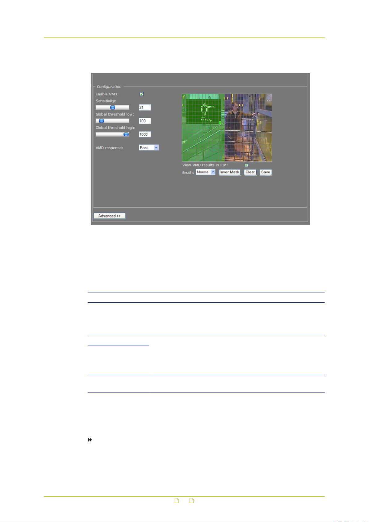
Video
11.8.2 Configure detection parameters
Video > VMD > Configuration
VMD enabled: Configuration section with controls, video picture, and motion detection inset, the latter
with mask applied. The mask permits motion detection in the right half of the picture only, at the top
of the stairs, so passers-by and cars would not be registered by the detector facility; neither will the
details in the background (the trees are reflected in the window pane though, and this could be
masked separately).
Item Description
Enable VMD Expands the Configuration section, as shown in the above figure.
Sensitivity This setting relates to local detection levels: local change is only
detected if its level exceeds a certain value. The sensitivity setting
can be used to eliminate unwanted ('false') triggering (e.g. caused
by background noise or constant local movement).
Global threshold low These settings relate to the summed amount of change within fully
Global threshold high
VMD response Fast or Filtered. Filtering is used to suppress a single peak as false
or partly unmasked portion(s) of the screen; a value between the
two thresholds gives rise to a corresponding VMD alarm. The level
of this alarm can be set (A-N) using separate TKH Security
software.
triggering.
11.8.3 Set the mask
To set a mask
● To edit the mask, click on the grid that is put over the image.
One or more mask elements at, and possibly around, that position, are produced.
76
Page 77
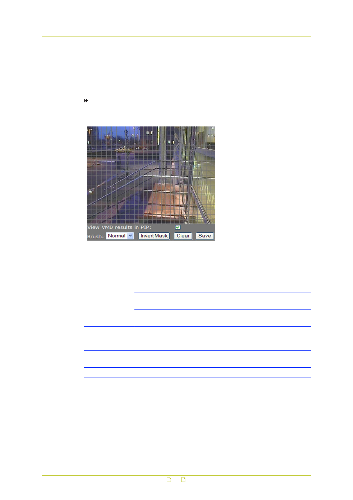
Video
● Hold the standard mouse button and drag, to 'brush' (i.e. mask) larger areas, with a
'Normal', 'Small', or 'Large' brush.
● Use the 'Invert Mask' button to reverse a selection.
● Hold the right mouse button and drag, to erase mask areas.
● Use the 'Save' button to store the mask in the unit.
To delete a mask
● Press the Clear button.
Masking grid
Item Description
Brush Normal Allows grid elements to be accessed in 4-
element groups.
Large Allows grid elements to be accessed in 16-
element groups.
Small Allows grid elements to be accessed one at a
time.
Invert Mask Enables you, for example, to start creating a mask by marking the
(smaller) area(s) you do wish to monitor and then use this button to
reverse the selection.
View VMD results
in PIP
Clear Clears the mask.
Save Makes the current mask effective and stores it for later use.
Inserts the Video Motion Detection inset providing feedback on current
VMD settings.
77
Page 78
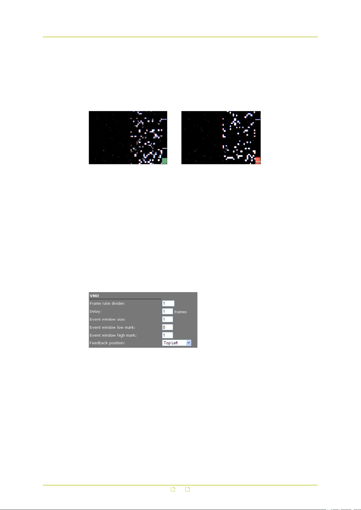
Video
11.8.4 VMD detection window
The VMD detection window shows up as a small picture within the larger picture. Depending
on the thresholds set, the motion detection bar on the right side of the picture shows up
green or red (see figures below), the latter indicating a VMD alarm will be generated. In the
pictures, the upper and lower thresholds are shown as two white markers. If the bar runs over
the highest marker, it will turn green again and there will be no alarm condition.
VMD detection windows, with mask applied to the left half of the window. The small white blocks
indicate grid elements where change occurred above the sensitivity level. The summed change is
reflected in the bars on the right, the green one (left) not reaching the lower threshold. The red
one (right picture) extending past it, since this threshold is set much lower.
11.8.5 VMD alarm
If movement is detected, a module alarm (VMD) will be generated and sent out over the
network using the (unsolicited) notification mechanism. Such alarms can be caught using
appropriate software.
11.8.6 Advanced
Video > VMD > Advanced > VMD
78
Page 79

Video
Item Description
Frame rate divider Range: [1...100]. Used to determine the number of frames used
for VMD. Only 1 divided by this value frames are evaluated.
Delay Range: [1...10] frames. The delay in frames between the currently
processed frame and the stored frame with which it is to be
compared.
Event window size Range: [1…32]. Number of frames evaluated at a time to
determine if there is a VMD alarm.
Event window low
mark
Event window high
mark
Feedback position Enables you to position the detection window (not to be confused
Note on Advanced VMD Settings: Motion is detected by comparing the current frame with
a reference image (e.g. a previous frame) and calculating the difference between the two.
The value you enter for the Event window size parameter determines how many frames are
evaluated for VMD purposes at a time. Not all frames from the original video stream are
used for VMD. Only 1 divided by the value set for the frame rate divider frames are
evaluated.
A VMD event becomes active when, within the Event window, the number of frames with
motion exceeds a configurable value, the Event window high mark. After this, the VMD event
will remain active until the number of frames with motion drops below another configurable
value, the Event window low mark.
Range: [0…31]. Thresholds determining if there is a VMD alarm.
with an event window).
79
Page 80
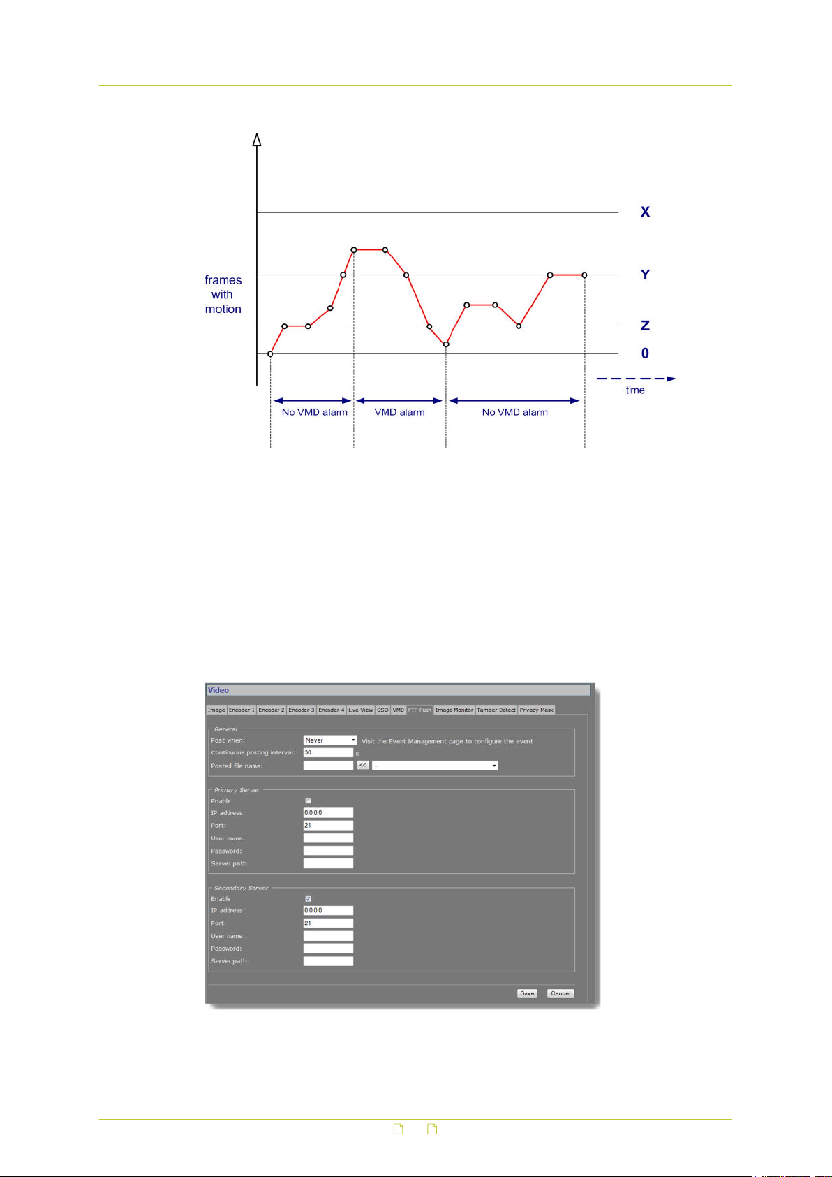
Video
VMD Alarm: Event window high/low mark
X = Event window size
Y = Event window high mark
Z = Event window low mark
VMD alarm becomes active when in at least Y out of X frames motion is detected.
VMD alarm becomes inactive when in at least Z out of X frames no motion is detected.
11.9 FTP Push
Video > FTP Push
80
Page 81

Video
11.9.1 Post JPEG images
The BC840-MC can be configured to upload images, generated by its Live View encoder, to an
FTP server. Posting the files in JPEG format can be set to be continuous or event-triggered. On
the Event Management page, one or more events can be associated with FTP Push.
11.9.2 General
Item Description
Post when Never No image posting
Event On Image is posted when configured event
Event Off Image is posted when configured event
Event Changed Images are posted when configured event
Continuous Posting not associated with any event. Images
Continuous
posting interval
Posted file name Enter a descriptive name. Use the Append list and button (<<) to
Append list Options to add information and file extension to the file name entered.
Range: [1-300] s. Applies to continuous posting only. Determines the
frequency of image posts.
include extra information to identify the files. The "$", "#", and "@"
symbols described below can also be typed directly after the name.
<UTC-Time/date>.jpg Time/date. Appended as "_$.jpg".
<SeqNr>.jpg Sequence number. Appended as "_#.jpg".
<SeqNr>_<UTCTime/date>.jpg
<SeqNr>_<Event
State>.jpg
<UTC-Time/
date>_<Event
State>.jpg
occurs.
ceases.
occurs or ceases.
are sent continuously at the frequency set for
the Continuous posting interval parameter.
Sequence number and time/date. Appended
as "_#_$.jpg".
Sequence number and event state. Appended
as "_#[email protected]". Examples of event state:
T=true, F=false.
Time/date and event state. Appended as "_
[email protected]".
11.9.3 FTP server
A target FTP server must hold a user account associated with the BC840-MC. You can assign a
primary server and a secondary server. Images are posted simultaneously to both the primary
server and secondary server.
81
Page 82
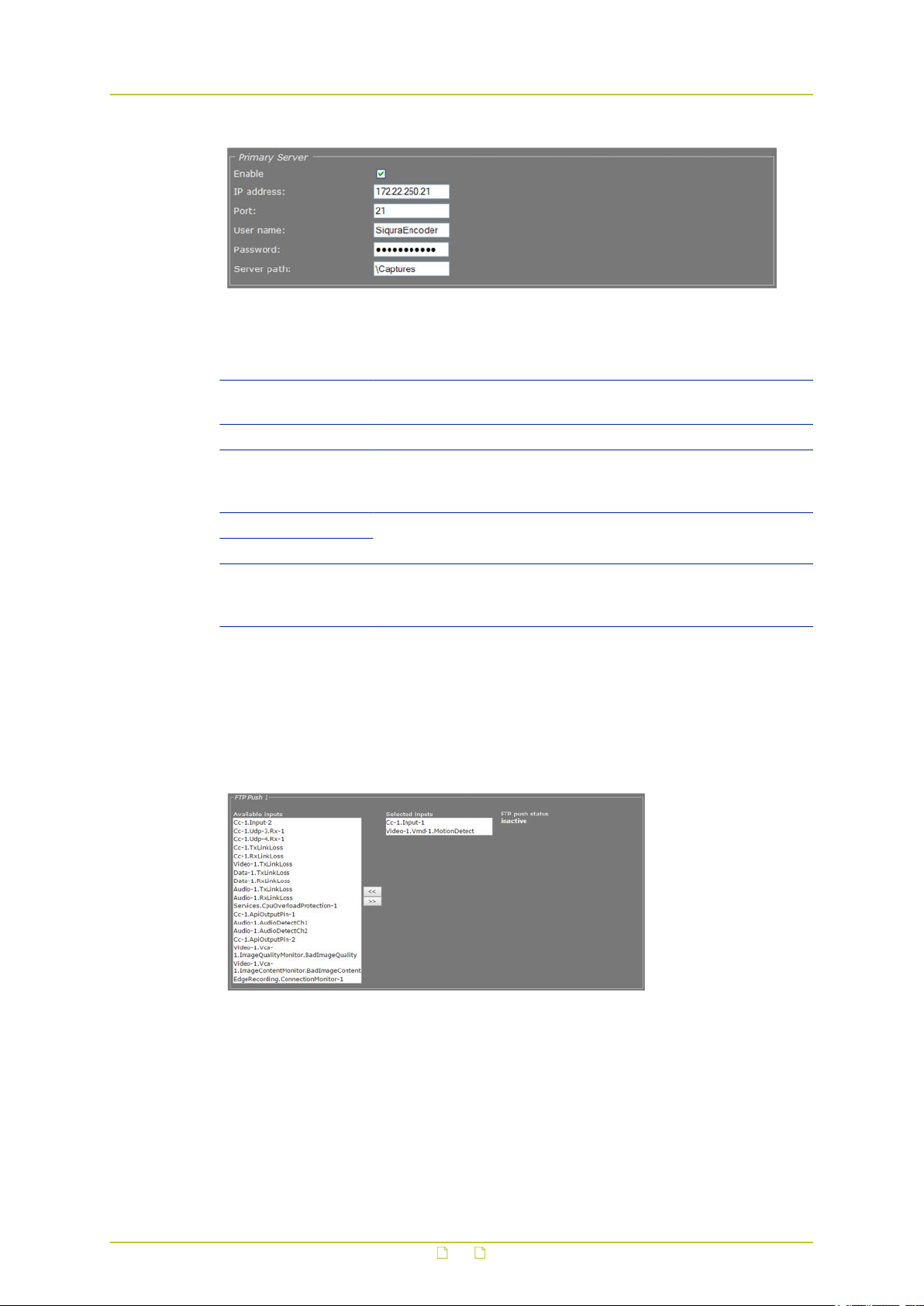
Video
Video > FTP Push > Primary Server, example settings
Item Description
Enable Select or clear to respectively enable/disable the connection with
this server.
IP address IP address of the FTP server.
Port The FTP protocol typically uses port 21 on the FTP server to listen
for clients initiating a connection. Port 21 is also where the server
is listening for commands issued to it.
User name The authorization to access the FTP server.
Password
Server path Folder on the FTP server assigned to the FTP client. To be used, for
example, if the client is not allowed to access the server root
folder.
11.9.4 Event management
Having selected Event On, Event Off, or Event Changed as a trigger, do not forget to go to the
Event Management page to associate one or more events with the FTP push.
Event Management > FTP Push 1. Two inputs associated with FTP Push.
11.9.5 Monitor and troubleshoot FTP Push
You can monitor FTP push on the Measurements tab of the Status page. Measurements on this
tab are continuously updated. In the FTP Push section, you can compare the number of
incoming triggers with the number of succeeded posts.
82
Page 83
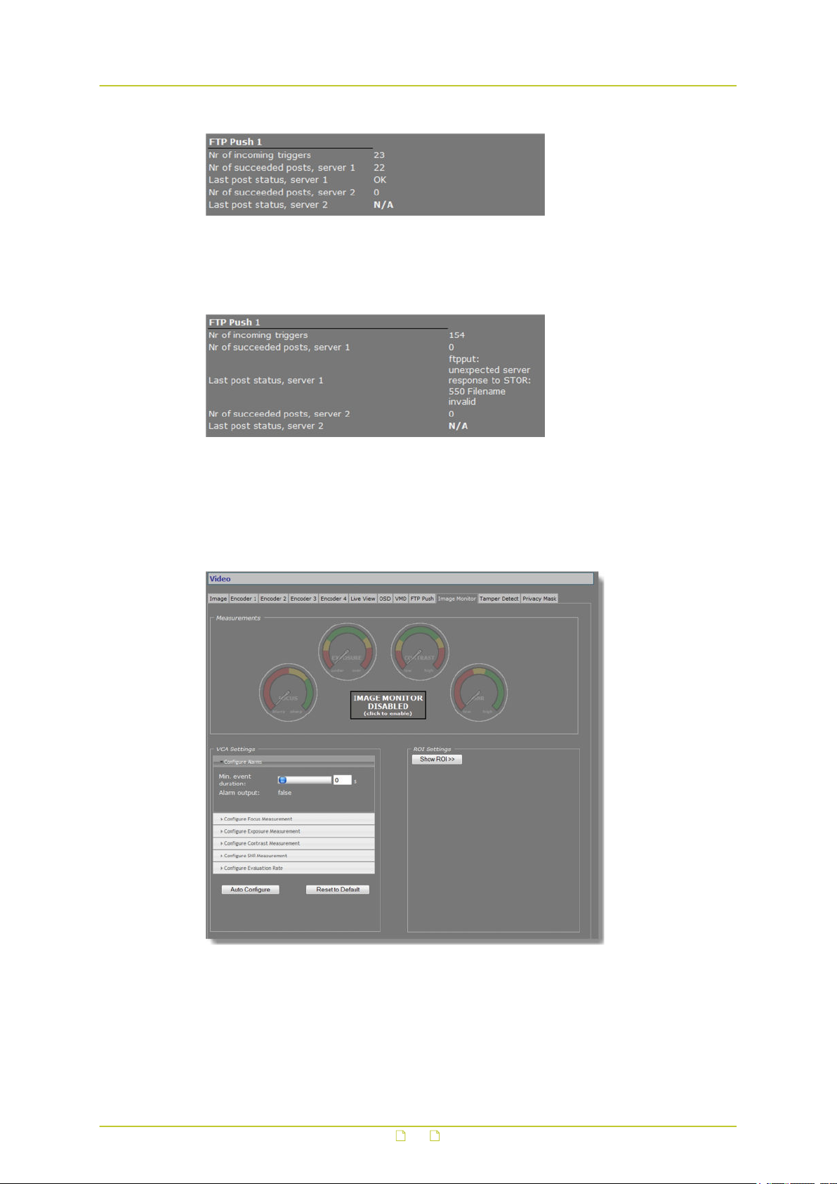
Video
Status > Measurements > FTP Push 1
If you need to troubleshoot the file upload process, the messages reporting the last post
status will in most cases point you to possible causes of problems.
Last post status: example of error message
11.10 Image Monitor
Video > Image Monitor
83
Page 84
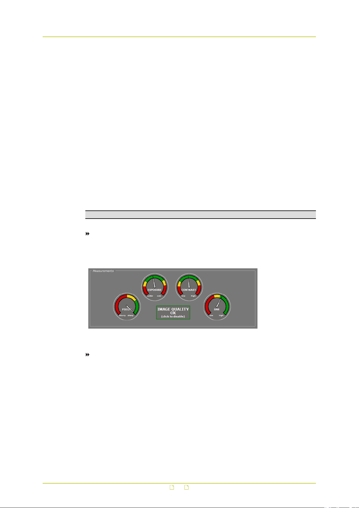
Video
11.10.1 Image quality check
The Image Monitor can detect if images produced by the camera are still usable. It can give
an indication of the performance of the camera and show whether or not it needs attention. A
quality check is made against what is normally a good picture.
Examples of detectable occurrences:
● The camera is in focus during sunny days, but out of focus in low light situations.
● The initial daytime camera position seemed ok, but streetlights and spot lights affect the
image during nighttime.
● The lens has got dirty.
● The iris control has got stuck.
● Camera failure.
11.10.2 Enable the Image Monitor
The Image Monitor can measure camera focus, exposure, contrast level, and SNR (Signal-toNoise Ratio). The four measurements are disabled by default. You can enable them
simultaneously or separately.
Note: Enabling/disabling a measurement also enables/disables the associated alarm.
To enable all measurements simultaneously
● In the Measurements section, click IMAGE MONITOR DISABLED.
The four dials are activated, the pointers indicating the current measurements.
Image Monitor: all measurements enabled
To enable/disable individual measurements
1 In the VCA Settings section, click the accordion style menu labelled with the
measurement you require.
The settings of the selected measurement display.
2 Select/Clear the Enable box to enable or disable the measurement, respectively.
84
Page 85
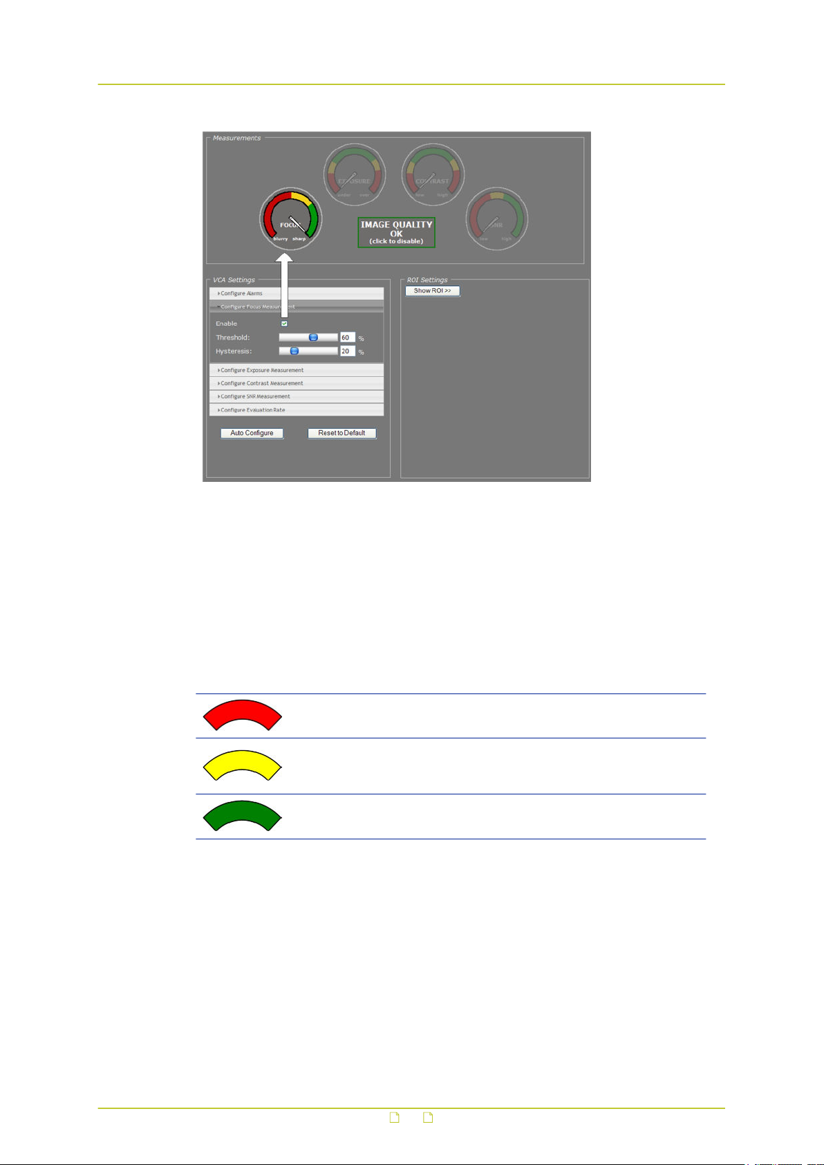
Video
Image Monitor: FOCUS measurement enabled only
11.10.3 Dial legend
The coloured dials in the Measurements section provide a quick and easy glance at the health
of the camera. You can fine-tune each measurement's alarm thresholds to your needs in the
VCA Settings section.
Dial legend
Error state.
Hysteresis: the area where the alarm output is either "true" or "false"
depending on the preceding alarm state, as illustrated in the figure
below.
Correct camera performance.
85
Page 86
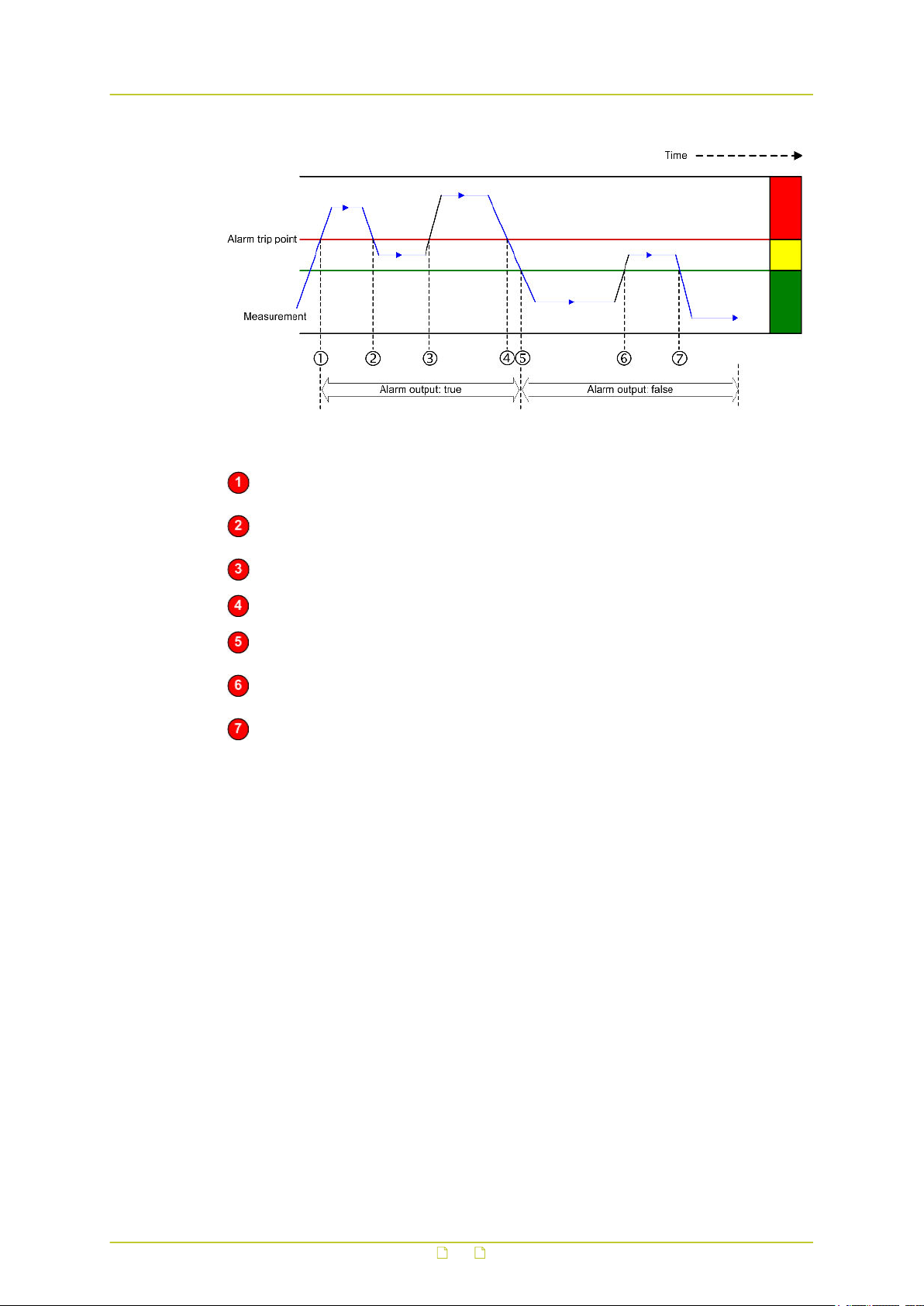
Video
Hysteresis and alarm output
The Measurement rises above the trip point. After expiry of the delay set for the Min.
event duration, the alarm is activated.
The Measurement drops into the Hysteresis area (i.e. the margin between incorrect
and correct performance) but falls short of the "safe" area. The alarm is continued.
The Measurement re-enters the Error state area. The alarm continues.
The Measurements drops into the Hysteresis area. The alarm continues.
Camera performance is correct. The alarm is deactivated after expiry of the Min.
event duration.
The Measurement rises into the Hysteresis area. The alarm trip point is not reached.
Alarm output remains "false".
Camera performance is correct. Alarm output remains "false".
86
Page 87
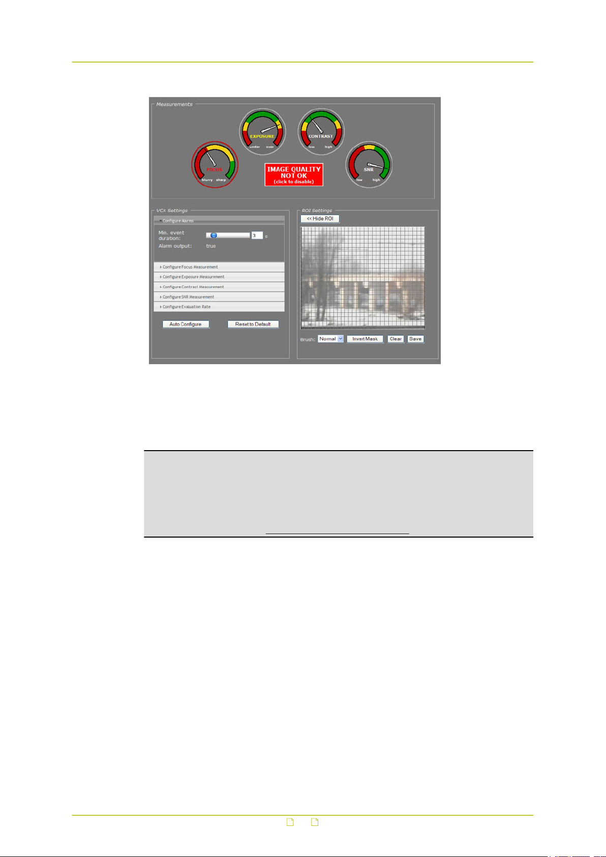
Video
Image Quality not OK: Alarm output = true
The red circle around the Focus dial in the figure above indicates that the alarm is raised by
the Focus measurement. The Exposure dial has no red circle, although the pointer is in the
Hysteresis area. This shows that Exposure was correct before and that this measurement in
itself is not the cause of the alarm.
Note: In addition to the visual indications on the web pages, alarms can also be read from
the BC840-MC 's internal Management Information Base (MIB) using appropriate software,
or through TKH Security's Open Streaming Architecture (OSA) - that is, the "SPI API". The
BC840-MC includes SNMP support for its image monitor and tampering detection. A trap is
sent when bad image quality or camera tampering has been detected and another one when
the situation returns to normal. This support requires a new SNMP MIB, the OPTC-VCA-MIB,
which can be downloaded at www.tkhsecurity.com/support-files.
87
Page 88

Video
11.10.4 Measurements configuration
Video > Image Monitor > VCA Settings
The default Measurements values will mostly work well for you. If you do need to modify them
you can do so in the VCA Settings section.
Item Description
Configure Alarms Min. event duration Alarm output delay time: the time span that is
to elapse before a continued change in
conditions actually activates/deactivates the
alarm output.
Alarm output True or False. Indication of current status.
Configure Focus
Measurement
Configure
Exposure
Measurement
Configure
Contrast
Measurement
Configure SNR
Measurement
Configure
Evaluation Rate
Auto Configure Adjusts the alarm thresholds, based upon the current measurements.
Reset to Default Restores the original thresholds. Does not affect the current activity
Allow you to enable/disable each measurement separately and
customise its alarm threshold and hysteresis to your requirements.
The value entered here determines the speed at which the host
machine processes the algorithms underlying the measurements.
Higher values take up more CPU power.
The green area is centred around the current pointer position.
status of the measurements (i.e. being Enabled or Disabled).
Tip: A PTZ camera moving from one preset to the next may trigger an alarm if the scene
change takes too long. Setting an appropriate time for the Min. event duration parameter
can delay the alarm output until the camera has adopted the new position and the alarm
condition has ceased.
88
Page 89
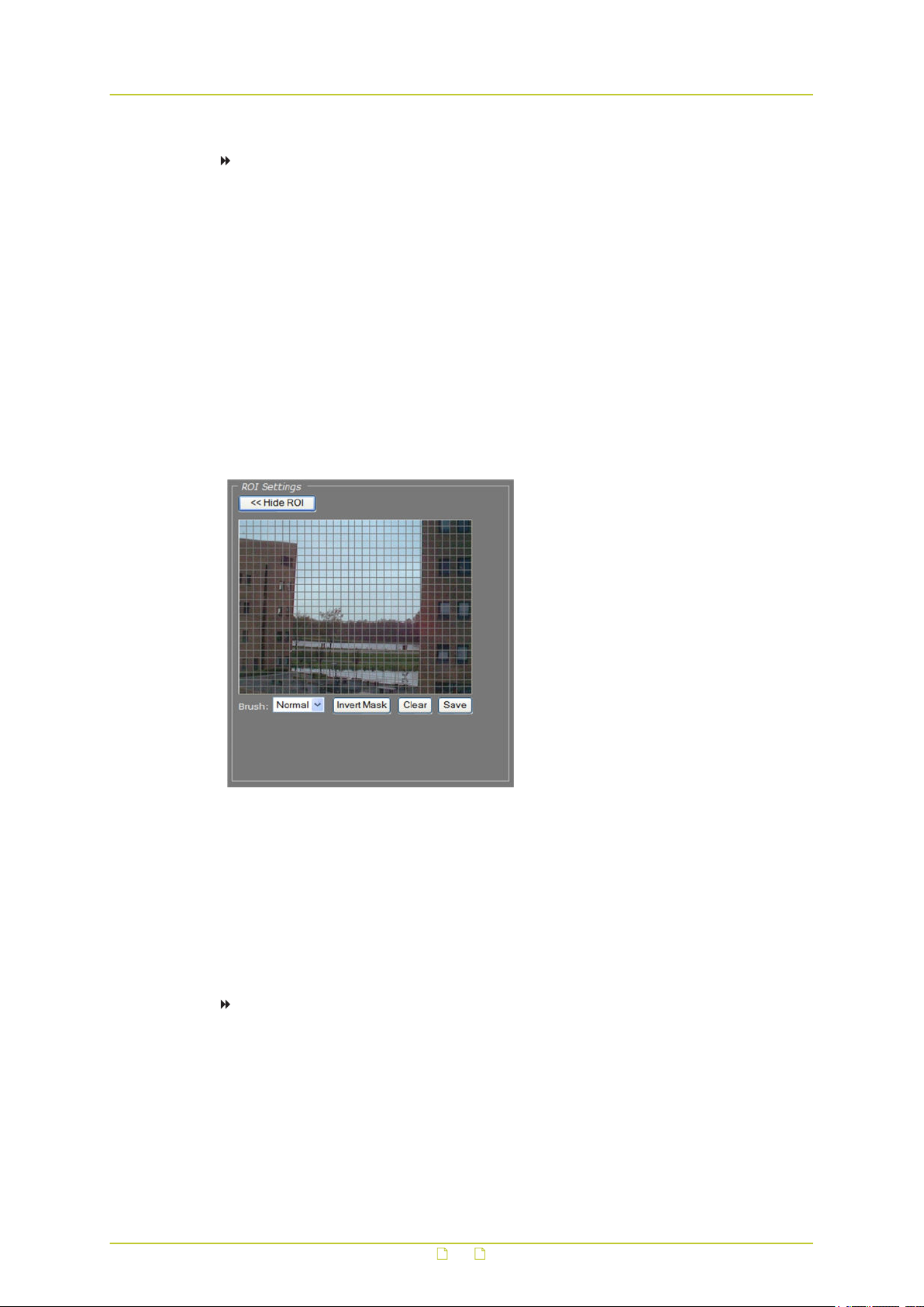
Video
To configure a measurement
1 In the VCA Settings section, click the button for the measurement you wish to configure.
The measurement's settings display.
2 Select the Enable box, if necessary.
3 Set the alarm threshold to your requirements.
Note that you can set two thresholds for Exposure (under- and overexposure) and
Contrast (low and high contrast).
4 Set the Hysteresis.
5 Click the Configure Alarms button and set the Min. event duration, if desired.
6 Click the Configure Evaluation Rate button and modify this setting, if desired.
11.10.5 Region of Interest (ROI)
Video > Image Monitor > ROI Settings
ROI preview
Pressing Show ROI>> in the ROI Settings section opens a preview with a grid overlay. You
can use it to mask portions of the image you wish to exclude from monitoring. Certain regions
can disrupt the measurements or be of no importance. You may want to filter out a bright
source of light, a region with low contrast, or differences in focus, for example. The part of the
image that you have not selected on creating the mask is called the Region of Interest (ROI).
To set a mask
● To edit the mask, click on the grid that is put over the image.
One or more mask elements at, and possibly around, that position, are produced.
● Hold the standard mouse button and drag, to 'brush' (i.e. mask) larger areas, with a
'Normal', 'Small', or 'Large' brush.
● Use the 'Invert Mask' button to reverse a selection.
● Hold the right mouse button and drag, to erase mask areas.
● Use the 'Save' button to store the mask in the unit.
89
Page 90
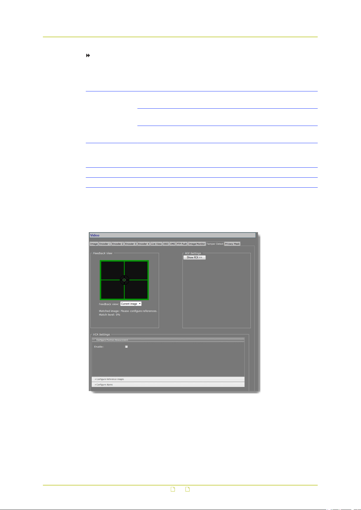
Video
To delete a mask
● Press the Clear button.
Item Description
Brush Normal Allows grid elements to be accessed in 4-
element groups.
Large Allows grid elements to be accessed in 16-
element groups.
Small Allows grid elements to be accessed one at a
time.
Invert Mask Enables you, for example, to start creating a mask by marking the
(smaller) area(s) you do wish to monitor and then use this button to
reverse the selection.
Clear Clears the mask.
Save Makes the current mask effective and stores it for later use.
11.11 Tamper Detect
Video > Tamper Detect
90
Page 91
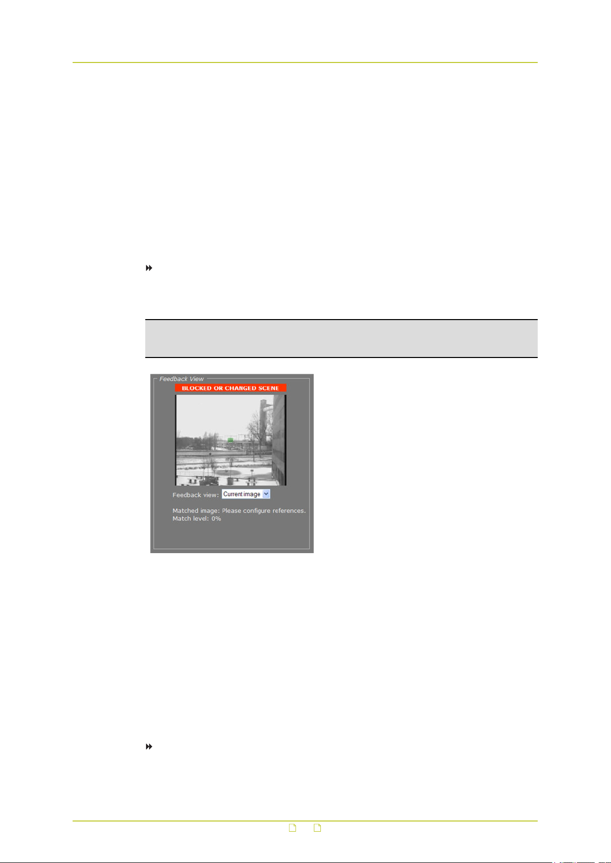
Video
11.11.1 Camera movement and scene changes
As a result of tampering, or more accidentally, after cleaning, a camera may no longer cover
the area designated for monitoring. The Tamper Detect function can detect camera position
changes and scene changes such as a blocked camera view, for example. It does so by
comparing the current image to one or more reference images that were captured and stored
earlier.
11.11.2 Enable Tamper Detect
Tamper Detect is disabled by default.
To enable Tamper Detect
● In the VCA Settings section, select Enable.
The Position Measurement settings are opened.
Important: If no reference images have been stored yet, a BLOCKED OR CHANGED SCENE
alarm displays in the Feedback View. Tamper Detect cannot find a match with the current
image. You will need to create one or more reference images first.
Tamper Detect enabled: No reference images found
11.11.3 Reference images
You can create up to 16 reference images. This enables you to store images captured in
different day/night situations and/or from multiple PTZ preset positions. When the camera
moves to a different preset Tamper Detect tries to match the new scene to the available
reference images.
11.11.3.1 Create a reference image
To create a reference image
1 In the VCA Settings section, click Configure Reference Images.
2 Open the Reference image list, and then select the image you want to create.
91
Page 92
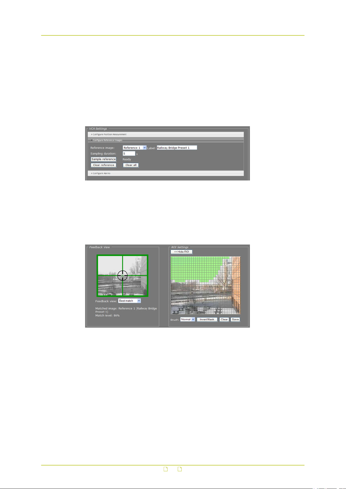
Video
3 Enter a descriptive name in the Label box.
4 Enter a value (in seconds) for the Sampling duration.
This parameter enables you to capture the background of a scene only and have specific
elements such as moving objects filtered out of the image. With a longer time span for
the sampling duration, persons passing in front of the camera, for example, or cars
driving on a highway can be smoothed out to prevent them from triggering a changed
scene alarm.
5 Click the Sample reference button.
The current image is sampled.
Reference image 1 created
11.11.3.2 Mask the ROI
You can use the ROI settings section to exclude portions of the image from monitoring, as
explained earlier in the Region of Interest section.
Region of less interest masked
11.11.3.3 Compare images
Tamper Detect compares the current scene with all available reference images. If a match is
found a green crosshair is superimposed on the image in the Feedback view. Information
about the matched image and the match level is displayed under the Feedback view.
The small green circle in the middle of the image indicates the amount of camera movement
that is allowed. A position alarm is raised when the green circle is outside the crosshair
centre. For information about adjusting the amount of allowed camera movement, see
Position Measurement.
If no match is found a BLOCKED OR CHANGED SCENE alarm is raised.
92
Page 93
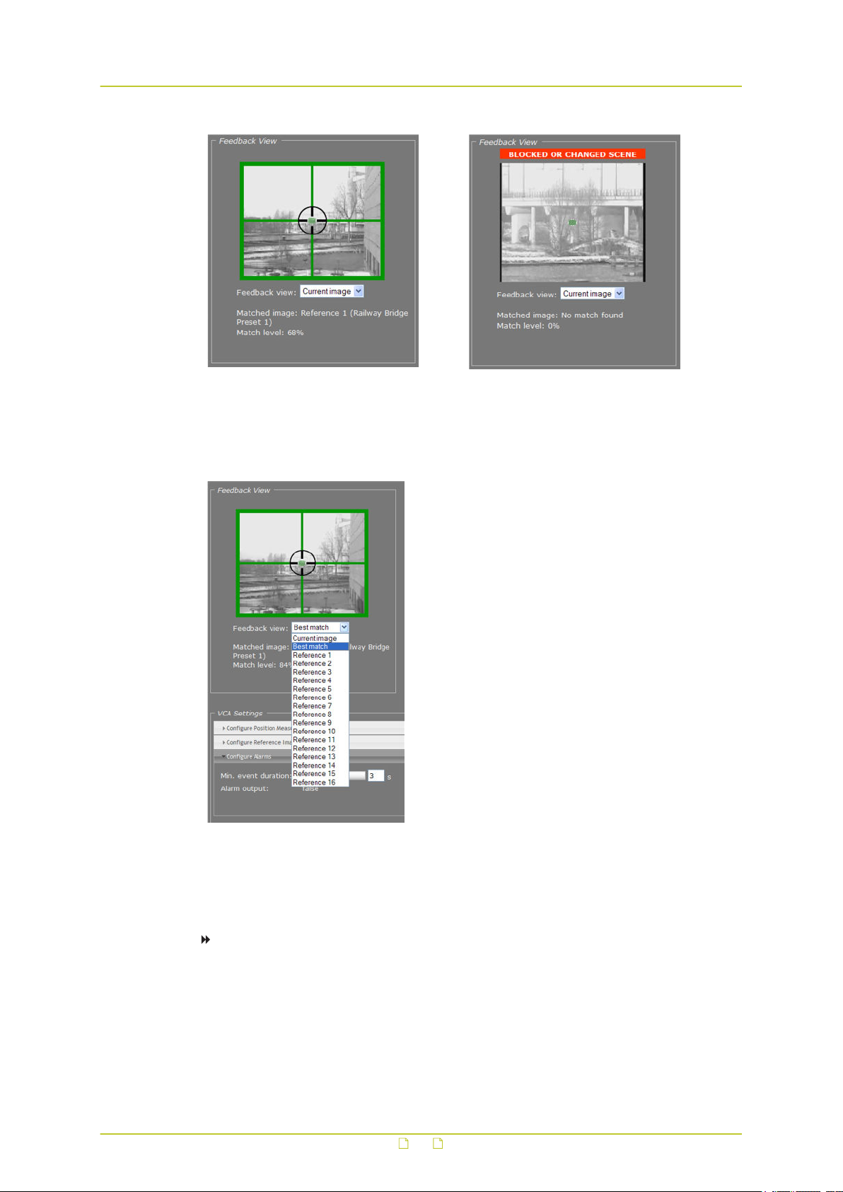
Video
Current image matches Reference 1 Reference image(s) available. No match found
The drop-down list in the Feedback View section can be used to display the current image, the
best matching reference image, or a specific reference image.
with current image, though.
Feedback view list
11.11.3.4 Delete a reference image
To delete a reference image
1 In the VCA Settings section, open the Reference image list.
2 Select the image you wish to delete.
3 Press Clear reference.
Note that the Clear all button deletes all available references.
93
Page 94

Video
11.11.4 Position measurement
Video > Tamper Detect > Position Measurement
After creating one or more reference images you can configure the Position Measurement
settings to define thresholds for allowed camera movement and image matching.
Item Description
Enable Enables Tamper Detect functionality.
Match threshold The current image and the reference image it is compared with are
considered a match upon reaching the degree of similarity specified
here. The lower the percentage entered for this parameter, the
fuzzier the match.
Match hysteresis This is the margin area where there is either a match or no match,
depending on the preceding match level. If your alarm output
frequently alternates between "true" and "false" you can use this
parameter to fine-tune your settings.
Position threshold Determines the amount of camera movement that is allowed
before a position alarm is raised. Raising this value allows more
camera movement. This is indicated by the increased size of the
green circle in the center of the image.
Evaluation rate The value entered here determines the speed at which the host
machine processes the algorithms underlying the measurements.
Higher values take up more CPU power.
Defaults Restores the original settings. Does not affect the current activity
status of Tamper Detect - that is, being Enabled or Disabled.
94
Page 95

Video
11.11.5 Alarms
Video > Tamper Detect > Configure Alarms
The Configure Alarms section enables you to view the current status of the alarm output and
to set a delay for the activation/deactivation of alarm outputs.
Note: In addition to the status indication in this section, alarms can also be read from the
BC840-MC 's internal Management Information Base (MIB) using appropriate software, or
through TKH Security's Open Streaming Architecture (OSA) - that is, the "SPI API". The
BC840-MC includes SNMP support for its image monitor and tamper detect functions. A trap
is sent when bad image quality or camera tampering has been detected and another one
when the situation returns to normal. This support requires a new SNMP MIB, the OPTCVCA-MIB, which can be downloaded at www.tkhsecurity.com/support-files.
Item Description
Min. event duration Alarm output delay time: the time span that is to elapse before a
continued change in conditions actually activates/deactivates the
alarm output.
Alarm output True or False. Indication of current status.
Tip: A PTZ camera moving from one preset to the next may trigger an alarm if the scene
change takes too long. Setting an appropriate time for the Min. event duration parameter
can delay the alarm output until the camera has adopted the new position and the alarm
condition has ceased.
95
Page 96
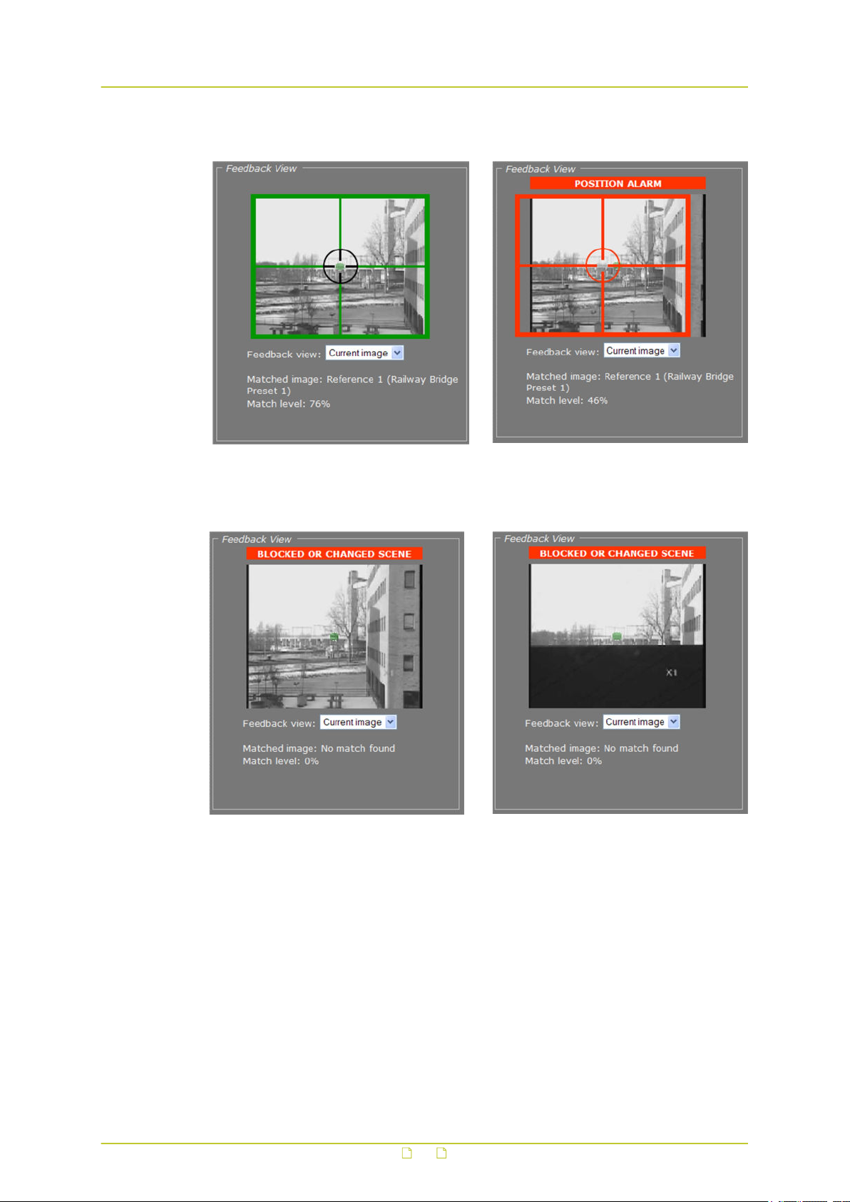
Video
11.11.5.1 Alarm examples
Original camera position Camera has moved to the right. Although the
current image still matches Reference 1, the
changed camera position results in a position
alarm.
Camera has moved further to the right.
Current image no longer matches any reference
image, resulting in a changed scene alarm.
96
Blocked scene alarm
Page 97
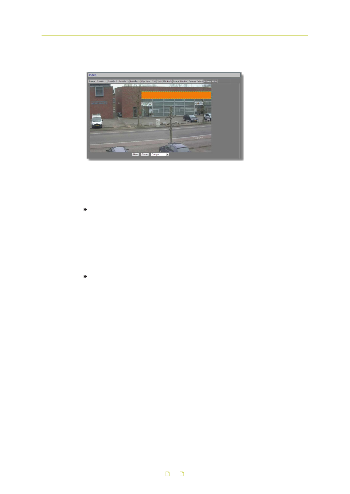
Video
11.12 Privacy Mask
Video > Privacy Mask
The privacy mask function aims to avoid intrusive monitoring. The BC840-MC supports up to
10 masks.
To create a privacy mask
1 On the Video page, click the Privacy Mask tab.
2 Under the preview, click New.
A square mask appears as an overlay in the centre of the preview.
3 Use the pointer to position and size the mask.
If desired, click to select the mask, and then select a mask colour from the list under the
preview.
To delete a mask
1 On the Video page, click the Privacy Mask tab.
2 Using the pointer, select the mask in the preview.
3 Click Erase.
97
Page 98
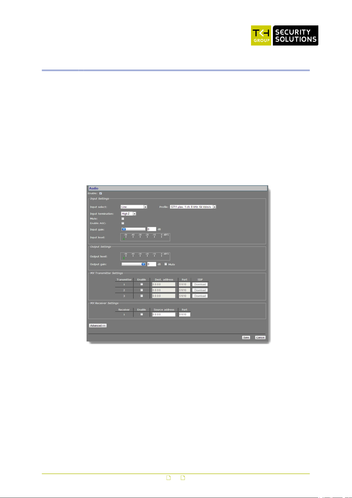
12 Audio
This chapter describes the functionality and settings found on the Audio page of the BC840MC.
In This Chapter
12.1 Enable audio.......................................................................................................98
12.2 Make audio connections......................................................................................100
12.3 Advanced......................................................................................................... 101
12.1 Enable audio
Audio page
Using the Enable check box at the top of the Audio page, you can enable/disable the entire
audio functionality (the latter, for example, to prevent unwanted eavesdropping). Remember
to Save the configuration to make it effective.
98
Page 99

Audio
12.1.1 Input Settings
Item Description
Input select Line, Microphone, or Microphone + bias.
Input
termination
Mute Audio on/off.
Enable AGC To adjust the gain to an appropriate level, Automatic Gain Control reduces
Input gain Range: [0…30] dB. Is disabled when AGC is enabled. Drag the sliding
Input level VU meter to display audio input level.
Profile Preset combinations of settings. A non-standard setting configured
Can be set to High-Z or 600 ohms, to match audio source. Single-ended.
the volume if the signal is strong and raises it when it is weaker.
button or type a value. Gain control reacts directly, without the need to
press Save.
through the Advanced Settings gives ‘--’ in the Profile selector.
G711 A-law. 1 ch. 8 kHz 64
kbit/s
G711 μ-law. 1 ch. 8kHz. 64
kbit/s
Legacy PCM ● 2 channels (stereo)
● default setting
● mainly used in Europe
● mono, low quality
● used for QuickTime
● mainly used in USA
● mono, low quality
● used for Genetec's Omnicast
● high quality, 15.7 kHz
12.1.2 Output Settings
Item Description
Output level VU meter to display audio output level.
Output gain Range: [-80…0] dB.
Mute Select/clear this box to mute/unmute audio.
99
Page 100

Audio
12.2 Make audio connections
Audio > MX Transmitter and MX Receiver Settings, two-way audio
Audio streams
The BC840-MC provides bidirectional audio. The BC840-MC can send three audio streams to
different destinations, multicast or unicast, to an A-80, or any C-/S-series codec with an audio
interface. It can also receive one audio stream from an A-80 or any C-/S-series codec that
features audio.
Highlighted fields
The source address and port number fields are highlighted in green when the enabled receiver
receives a stream from the specified source. The two fields are marked in red when no stream
is received with the receiver enabled and correctly configured.
Two-way audio
The figure above shows the setup for two-way audio on the side of the BC840-MC. The device
on the other side of the connection (with the IP address 172.22.250.131) would need similar
settings, that is - it must hold the IP address of the BC840-MC as the destination and source.
Transmitters and receivers must be enabled in order for streaming to start. Remember to
Save a configuration to make it effective.
SDP download
Use the SDP Download button to download a Session Description Protocol (SDP) file from the
encoder. SDP files contain streaming media initialisation parameters and properties. An SDP
file does not deliver media itself but through file association the media stream can be opened
in media players such as QuickTime and VLC. You can also use the SDP file to specify the URI
in your web browser.
12.2.1 MX Transmitter Settings
Item Description
Enable Select/Clear to enable/disable the stream transmission,
respectively.
Dest. address IP address of the codec that will receive the stream.
Port The local port number of the codec that will receive the stream.
SDP To download a Session Description Protocol (SDP) file from the
encoder, click the Download button.
100
 Loading...