

Page 1
English Manual
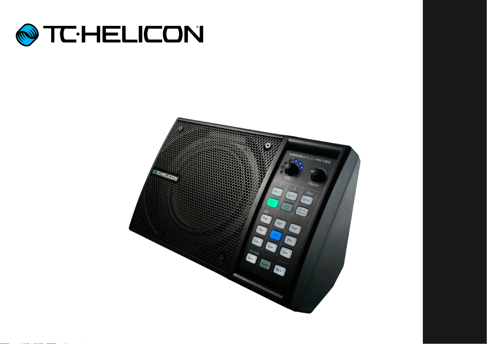
VoiceSolo FX150
Page 2

Important safety instructions 1
Before you begin 4
Introduction 7
Set up – aka
“Where do I put this thing?” 9
Connecting – aka
“Exploring the ins and outs” 11
Input 1: combo jack for XLR or ¼” input 12
Input 2: combo jack for XLR or ¼” input 12
Aux input 12
Out 13
USB connector 13
Monitoring explained 14
Show me how! 17
Solo singer 18
Solo singer using a TC-Helicon
vocal processor 19
Solo singer using a TC-Helicon
vocal processor (alternate) 20
Two singers 21
Singer with acoustic guitar 22
Singer with electric guitar 23
Singer with guitar and 3rd party
guitar effects processor 24
Singer & acoustic guitarist in
a band with monitor mix 25
Singer & acoustic guitarist in
a band with monitor mix (alternate) 26
Singer & electric guitarist in
a band with monitor mix 27
Singer with a TC-Helicon
processor in a band with monitor mix 28
Singer & guitarist with a TC-Helicon
processor in a band with monitor mix 29
Singer & guitarist with a 3rd party guitar
processor in a band with monitor mix 30
Controls – aka
“Pushing buttons” 31
Advanced controls 34
Technical Specifications 36
Product VoiceSolo FX150
Product (firmware) version 1.11
Document Reference manual
Document version / date 2014-04-25
VoiceSolo FX150 Reference manual a
Page 3

Important safety instructions
Important safety instructions
VoiceSolo FX150 Reference manual 1
Page 4

Important safety instructions
1. Read these instructions.
2. Keep these instructions.
3. Heed all warnings.
4. Follow all instructions.
5. Do not use this apparatus near water.
6. Clean only with a dry cloth.
7. Do not block any ventilation openings. Install in accordance with the manufacturer’s
instructions.
8. Do not install near any heat sources such
as radiators, heat registers, stoves, or other
apparatus (including amplifiers) that produce heat.
9. Do not defeat the safety purpose of the polarized or grounding-type plug. A polarized
plug has two blades with one wider than
the other. A grounding-type plug has two
blades and a third grounding prong. The
wide blade or the third prong is provided for
your safety. If the provided plug does not fit
into your outlet, consult an electrician for
replacement of the obsolete outlet.
10. Protect the power cord from being walked
on or pinched, particularly at plugs, convenience receptacles, and the point where
they exit from the apparatus.
11. Only use attachments/accessories specified by the manufacturer.
12. Use only with a cart, stand, tripod,
bracket, or table specified by the
manufacturer, or sold with the apparatus. When a cart is used, use
caution when moving the cart/apparatus
combination to avoid injury from tip-over.
13. Unplug this apparatus during lightning
storms or when unused for long periods of
time.
14. Refer all servicing to qualified service personnel. Servicing is required when the apparatus has been damaged in any way,
such as power-supply cord or plug is damaged, liquid has been spilled or objects
have fallen into the apparatus, the apparatus has been exposed to rain or moisture,
does not operate normally, or has been
dropped.
Caution
You are cautioned that any change or modifications not expressly approved in this manual
could void your authority to operate this equipment.
Service
– All service must be performed by qualified
personnel.
– There are no user-serviceable parts inside.
Warning
– To reduce the risk of fire or electric shock, do
not expose this apparatus to rain or moisture
and objects filled with liquids, such as vases,
should not be placed on this apparatus.
– This apparatus must be earthed.
– Use a three wire grounding type line cord like
the one supplied with the product.
– Be advised that different operating voltages
require the use of different types of line cord
and attachment plugs.
– Check the voltage in your area and use the
correct type.
Voltage Line plug according to standard
110 to 125V UL817 and CSA C22.2 no42.
220 to 230V CEE7 page VII, SR section 107-
2-D1 / IEC83 page C4.
– This equipment should be installed near the
socket outlet and disconnection of the device
should be easily accessible.
– To completely disconnect from AC mains, dis-
connect the power supply cord from the AC
receptacle.
– The mains plug of the power supply shall re-
main readily operable.
– Do not install this device in a confined space.
– For use at an altitude of 2000m or lower.
– Do not open the unit – risk of electric shock
inside.
VoiceSolo FX150 Reference manual 2
Page 5

Important safety instructions
EMC / EMI
Electromagnetic compatibility /
Electromagnetic interference
This equipment has been tested and found to
comply with the limits for a Class B digital device, pursuant to part 15 of the FCC rules.
These limits are designed to provide reasonable
protection against harmful interference in residential installations. This equipment generates,
uses and can radiate radio frequency energy
and, if not installed and used in accordance with
the instructions, may cause harmful interference
to radio communications. However, there is no
guarantee that interference will not occur in a
particular installation.
If this equipment does cause harmful interference to radio or television reception, which can
be determined by turning the equipment off and
on, the user is encouraged to try to correct the
interference by one or more of the following
measures:
For customers in Canada
This Class B digital apparatus complies with Canadian ICES-003.
Cet appareil numérique de la classe B est
conforme à la norme NMB-003 du Canada.
Explanation of graphic symbols
The lightning bolt triangle is used to
alert the user to the presence of uninsulated “dangerous voltages” within
the unit’s chassis that may be of sufficient magnitude to constitute a risk of
electric shock to humans.
The exclamation point triangle is used
to alert the user to presence of important operating and service instructions
in the literature accompanying the
product.
– Reorient or relocate the receiving antenna.
– Increase the separation between the equip-
ment and receiver.
– Connect the equipment into an outlet on a cir-
cuit different from that to which the receiver is
connected.
– Consult the dealer or an experienced ra-
dio / TV technician for help.
VoiceSolo FX150 Reference manual 3
Page 6

Before you begin
Before you begin
VoiceSolo FX150 Reference manual 4
Page 7

Before you begin
About this manual
This reference manual will help you learn understanding and operating your VoiceSolo FX150.
You can download the most current version of
this reference manual from
tc-helicon.com/products/voicesolo-fx150/support
To get the most from this reference manual,
please read it from start to finish, or you may
miss important information.
Getting support
If you still have questions about the product after reading this reference manual, please get in
touch with TC-Helicon Support:
tc-helicon.com/support/
Please register your
VoiceSolo FX150
To register your VoiceSolo FX150 using the
VoiceSupport software, launch VoiceSupport
and click on the ACCOUNT button.
! Please note that registration of your product is
NOT required to use VoiceSupport, download
presets, update firmware or contact support.
VoiceSolo FX150 Reference manual 5
Page 8
Before you begin
FX150
HI Z
FULL MIX
Master
Edit
HI Z
FULL MIX
Master
Edit
XLR Male XLR Female
Combo Jack
MIDI Jack
1/4 inch jack
XLR Male XLR Female
Combo Jack
MIDI Jack
1/4 inch jack
Power Input
Mini USB
1/8 inch jack GRND Lift
USB Type A
USB Type B
XLR Male XLR Female
Combo Jack
MIDI Jack
1/4 inch jack
Power Input
Mini USB
1/8 inch jack GRND Lift
USB Type A
USB Type B
XLR Male XLR Female
Combo Jack
MIDI Jack
1/4 inch jack
XLR Male XLR Female
Combo Jack
MIDI Jack
1/4 inch jack
Power Input
Mini USB
1/8 inch jack GRND Lift
USB Type A
USB Type B
XLR Male XLR Female
Combo Jack
MIDI Jack
1/4 inch jack
Power Input
Mini USB
1/8 inch jack GRND Lift
USB Type A
USB Type B
XLR Male XLR Female
Combo Jack
MIDI Jack
1/4 inch jack
Power Input
Mini USB
1/8 inch jack GRND Lift
USB Type A
USB Type B
XLR Male XLR Female
Combo Jack
Power Input
Mini USB
1/8 inch jack GRND Lift
USB Type A
USB Type B
Power Input
XLR Male XLR Female
Power Input
1/8 inch jack GRND Lift
XLR Male XLR Female
Combo Jack
MIDI Jack
1/4 inch jack
Power Input
Mini USB
1/8 inch jack GRND Lift
USB Type A
USB Type B
Diagrams
– The box in the lower left corner shows what
Legend
signals you will hear from your VoiceSolo
FX150.
VoiceSolo FX150 back panel
– The box in the lower right corner shows what
you will hear from your mixer / PA speakers.
When we refer to a “P.A.” or a “mixer” in this
Microphone
manual, we actually mean any sound gathering and sound producing sources. This could
be anything from a “stick system” or a portable/all-in-one loudspeaker system to powered
Acoustic guitar
studio monitors or even a DAW recording interface.
Electric guitar
– Please note that we do not account for other
inputs or instruments in these diagrams – so
Keyboard or other instrument
you won’t see pictures of drums etc.
– There are separate diagrams for hooking up
TC-Helicon vocal processors. Some of our
processors come with a headphone output
and some don’t. We will try to account for
both cases.
– We have tried to put as many combinations
and examples into our diagrams as possible,
but we may have missed one or two. Using the
complete set of diagrams, you should be able
to create your own unique connection setup.
Just bear in mind the key points, like whether
you need to press the FULL MIX/CH1 button.
TC-Helicon processor
Guitar FX processor
Mixing desk
P. A.
Monitor mix
To give you clear and concise representations
of what goes where, we have provided several
connection diagrams in the “Connecting – aka
“Exploring the ins and outs”” on page 11 section. There are a few things we would like you to
keep in mind as you follow these diagrams:
– Signal sources that go into your VoiceSolo
FX150 (e.g. microphone or guitar) will always
be shown to the left of the back panel image
(1).
– “Downstream” devices (mixers, speakers) will
always be shown to the right of the back panel
image (2).
– There are two “call out” boxes on the left side
of each diagram, showing whether or not the
HI Z button and the FULL MIX/CH1 button are
pressed.
Pressed Not pressed
VoiceSolo FX150 Reference manual 6
XLR cable
TRS cable
TS (guitar) cable
1/8” cable
Page 9

Introduction
Introduction
VoiceSolo FX150 Reference manual 7
Page 10

Introduction
Thank you for purchasing the
TC-Helicon VoiceSolo FX150!
In a live setting, getting a good monitor sound
can be extremely challenging. If you are fortunate enough to have a dedicated monitor engineer going from gig to gig with you, then you
probably aren’t reading this manual anyway – so
let’s get to the rest of us.
If you can’t hear yourself sing, play or speak, you
can’t perform at your best. Getting feedback (the
good kind) allows you to adjust your mix, your
pitch, intensity and many other facets of your
performance, giving your audience the best possible experience.
Get ready to elevate your live performances with
this flexible and powerful personal stage monitor!
In the box: the goodie list
The VoiceSolo FX150 box should contain the following items:
– VoiceSolo FX150
– Power supply
– Vertical mount adapter
– Multilingual quick guide
If you are missing an item, please contact your
retailer immediately.
Inspect all items for signs of transit damage. In
the unlikely event of transit damage, inform the
carrier and supplier.
If damage has occurred, keep all packaging as it
can be used as evidence of excessive handling
force.
Now, let’s get to the setup!
VoiceSolo FX150 Reference manual 8
Page 11

Set up – aka “Where do I put this thing?”
Set up – aka
“Where do I put this thing?”
VoiceSolo FX150 Reference manual 9
Page 12
Set up – aka “Where do I put this thing?”
The first thing we should do is figure out where
you are going to put the FX150. You have got a
few options, depending on your situation.
Mic stand mount
This is our preferred location. It’s nice and close
at hand for adjustments. It also provides a great
angle for crystal clear sound.
To connect the FX150 to your mic stand:
Tabletop or floor
“Click”
Some mic stands have a “thinner” top post. If
this is the case for you, the ideal mounting location for your FX150 is directly on top of the
tightening mechanism (or “chuck”) between your
lower and upper mic stand sections.
VoiceSolo FX150 Reference manual 10
Page 13

Connecting – aka “Exploring the ins and outs”
Connecting – aka
“Exploring the ins and outs”
VoiceSolo FX150 Reference manual 11
Page 14

Connecting – aka “Exploring the ins and outs”
Input 1: combo jack for XLR or ¼” input
A. This is where you will plug in your microphone,
guitar or other instrument.
B. If you are using a guitar without a preamp,
plug it in here and press the “Hi Z” button next
to the input.
Input 2: combo jack for XLR or ¼” input
A. This input is great for a second mic, a pre-
amped guitar or another line level instrument.
B. Input 2 can also act as a monitor input if your
mixing board is capable of sending a monitor
mix.
We will explore monitor mixes and their use on
the upcoming pages.
Aux input
The 1/8” input is perfect for two different types
of connections.
– If you are playing to backing tracks, use the
Aux jack to connect your media player.
– If you use a TC-Helicon (or 3rd party) vocal/
guitar processor, connect the processor’s
headphone out to the FX150’s Aux jack.
This setup can also give you a second chan-
nel of “More ME!” which we will discuss in the
monitor mix sections.
FX150
“How do I know if I have a preamp in my guitar?”
– Electric guitars: It’s uncommon to have a
preamp in any electric guitar. Use Input 1 with
the “Hi Z” button pressed.
– Acoustic guitars: Does your guitar need a
battery? That’s an easy way to tell if you have
an onboard preamp. If you are unsure, contact
your guitar manufacturer to find out what your
guitar is using.
VoiceSolo FX150 Reference manual 12
Page 15

Connecting – aka “Exploring the ins and outs”
Out
This XLR output can operate in two ways, depending on whether you are using Input 2 as
a “normal” input for guitar/vocals etc. or for a
monitor mix coming from the Front-of-House
(FOH) mixer.
First we will cover FULL MIX:
When using Inputs 1 & 2 for guitar/vocals etc.,
the OUT will send “what you hear” coming from
the FX150’s speaker to a PA or mixer. This output
also contains sounds from the AUX input.
Next, we will cover CH1 mode:
FX150
A. When you have pressed the FULL MIX/CH1
switch, the OUT will send only the sounds
from Input 1.
B. The combination of Input 1, Input 2 (Monitor
Mix) and Aux is what you will hear from the
FX150’s speaker.
C. You will only hear Input 1 coming from the P.A.
USB connector
The USB connector on the FX150 allows for updates of the unit’s firmware (if and when such an
update is released).
Updating firmware is done via our VoiceSupport
program. You can download VoiceSupport at
tc-helicon.com/products/voicesupport/
The USB connector does not pass audio.
When looking at the diagram above, keep the
“Diagrams” (page 6) section in mind. Grey
lines represent cables and the images in the
This is the most likely way a solo performer will
use the FX150, especially in a smaller venue.
VoiceSolo FX150 Reference manual 13
bottom boxes show “What you hear” from your
FX150 and from the P.A.
The P.A. images only show signals that “belong”
to you. We don’t show the rest of the band.
Page 16

Monitoring explained
Monitoring explained
VoiceSolo FX150 Reference manual 14
Page 17

Monitoring explained
What is a Monitor Mix?
Typically, in a reasonably sized venue, you will
have a few wedge style monitors on stage.
The Front-of-House (FOH) engineer (better
known as the sound guy or gal) can route signals from the main mixer back to the stage. This
is called a monitor or cue mix.
In an ideal situation, each person on stage will
get a unique blend of the instruments they wish
to hear through their monitor.
In a lot of venues, the number of monitor mixes
is limited to one or two (or none, ugh). If there are
two mixes, the lead singer usually commandeers
one mix (jerk!) and the band shares the other.
This is less than ideal, since each band member
probably wants to hear a bit more of themselves
relative to the other instruments.
The FX150 allows you to use a single mix and
add “More ME!” to that signal.
Using Input 2 as a Monitor Input
D
E
CH1
FX150
B
C
A. The FOH engineer sends a fairly even “moni-
tor” mix of all instruments to the stage.
B. Plug that “monitor” mix cable into Input 2 on
the FX150.
C. Press the FULL MIX/CH1 switch.
D. Plug your microphone or instrument into Input
1.
E. The FOH engineer uses the FX150’s OUT to
get your signal back to the main mixer. Be-
cause you pressed the FULL MIX/CH1 switch,
only the signal from Input 1 gets sent to the
FOH mixer. This prevents a feedback loop in
the monitor signal path.
A
A. Input 1 contains your primary (“More ME!”)
signal.
B. Input 2 contains the monitor mix (everything
else).
C. Aux contains your secondary (“More ME!”)
signal.
By adjusting the levels of Input 1, Input 2 and Aux
relative to each other, you can create your own
custom mix with as much “ME!” as you like!
Drums Guitar Keyboard Vocals
If you plug a media player or multi effect unit (via
Input 1 Input 2 Aux
its headphone out) into the AUX while CH1 is en-
Cue Mix More me
“More me” for a singer
gaged, you will ONLY hear those sounds through
your FX150’s speaker. The signal will NOT be
passed via the OUT. You will need to connect the
“More me” mix
main output from your multi effect unit to the PA.
Now here comes the best part…
VoiceSolo FX150 Reference manual 15
Page 18

Monitoring explained
Monitor THRU Connections
OR
If you have multiple VoiceSolo FX150 units on
stage, you can “daisy chain” them all together
using Input 2 and THRU, as shown above.
A. At the first FX150, plug the FOH monitor mix
into INPUT 2.
B. Press the FULL MIX/CH1 switch.
C. Connect an XLR cable between THRU on the
first FX150 and INPUT 2 on the next FX150.
D. Remember to press the FULL MIX/CH1 switch
on the second FX150 as well.
E. Repeat the process for each FX150 on stage.
Here are some examples of how “More ME!”
might look and sound for different musicians in
a band.
Drums Guitar Keyboard Vocals
Cue Mix More me
“More me!” vocals
Drums Guitar Keyboard Vocals
Cue Mix More me
“More me!” guitar
Drums Guitar Keyboard Vocals
Cue Mix More me
“More me!” guitar & vocals
The “More me! guitar & vocals” example is a
special case. Here, a multi effect unit’s headphone output is connected to the FX150 Aux
input, while the multi effect unit’s main outs are
connected to the FOH mixer.
! Remember that you will need to connect each
Drums Guitar Keyboard Vocals
FX150’s OUT to the FOH mixer!
Cue Mix More me
Depending on what’s plugged into Input 1 and
Aux on each FX150, each performer can have
“More me!” keyboards
their own “More ME!” mix.
VoiceSolo FX150 Reference manual 16
Page 19

Show me how!
Show me how!
VoiceSolo FX150 Reference manual 17
Page 20

Show me how!
Solo singer
A. Plug your microphone into Input 1.
B. Connect the FX150’s OUT to your PA’s Mixer.
C. Got backing tracks? Connect your audio
source to the AUX using a 1/8” cable.
FX150
VoiceSolo FX150 Reference manual 18
Page 21

Show me how!
Solo singer using a TC-Helicon vocal processor
A. Plug in your TC-Helicon unit into Input 1.
B. Connect the FX150’s OUT to your PA’s Mixer.
C. Got backing tracks? Connect your audio
source to the AUX using a 1/8” cable.
FX150
VoiceSolo FX150 Reference manual 19
Page 22

Show me how!
Solo singer using a TC-Helicon vocal processor (alternate)
A. Plug your TC-Helicon unit’s headphone out
into the FX150’s AUX.
B. Connect the FX150’s OUT to your PA’s Mixer.
This setup leaves Inputs 1 and 2 free for other
mics or instruments. You will have to figure out
how to crowd all those people around the FX150
though.
If your TC-Helicon processor has an AUX input,
you can connect your media player there to add
backing tracks to the signal. Use the mixer in
your TC-Helicon processor to balance the vocals
and backing track.
FX150
VoiceSolo FX150 Reference manual 20
Page 23

Show me how!
Two singers
A. Plug your microphone into Input 1.
B. Plug your singing partner’s microphone into
Input 2.
C. Connect the FX150’s OUT to your PA’s Mixer.
D. Got backing tracks? Connect your audio
source to the AUX using a 1/8” cable.
B
FX150
VoiceSolo FX150 Reference manual 21
Page 24

Show me how!
Singer with acoustic guitar
A. Plug your microphone into Input 1.
B. Plug your guitar into Input 2.
C. Connect the FX150’s OUT to your PA’s Mixer.
D. Got backing tracks? Connect your audio
source to the AUX using a 1/8” cable.
FX150
VoiceSolo FX150 Reference manual 22
Page 25

Show me how!
Singer with electric guitar
A. Plug your guitar into Input 1.
B. Plug your microphone into Input 2.
C. Connect the FX150’s OUT to your PA’s Mixer.
D. Got backing tracks? Connect your audio
source to the AUX using a 1/8” cable.
Don’t forget to press the HI Z switch!
FX150
VoiceSolo FX150 Reference manual 23
Page 26

Show me how!
Singer with guitar and 3rd party guitar effects processor
A. Plug your mic into Input 1.
B. Connect the headphone out from your 3rd
party processor into the FX150’s AUX using an
1/8” cable.
C. Connect the FX150’s OUT to your PA’s Mixer.
FX150
VoiceSolo FX150 Reference manual 24
Page 27

Show me how!
Singer & acoustic guitarist in a band with monitor mix
A. Plug your microphone into Input 1.
B. Plug the Monitor Mix from FOH into Input 2.
C. Connect the FX150’s OUT to your PA’s Mixer.
D. Plug your guitar into an input on your PA’s mix-
er.
Don’t forget to press the FULL MIX/CH1 switch!
FX150
VoiceSolo FX150 Reference manual 25
Page 28

Show me how!
Singer & acoustic guitarist in a band with monitor mix (alternate)
A. Plug your guitar into Input 1.
B. Plug the Monitor Mix from FOH into Input 2.
C. Connect the FX150’s OUT to your PA’s Mixer.
D. Plug your mic into an input on your PA’s mixer.
Don’t forget to press the FULL MIX/CH1 switch!
This is a good configuration for a worship setup.
Typically the vocal monitor mix is quite good but
you may have trouble hearing your instrument.
This allows “More ME!” for guitar.
FX150
VoiceSolo FX150 Reference manual 26
Page 29

Show me how!
Singer & electric guitarist in a band with monitor mix
A. Plug your microphone into Input 1.
B. Plug the Monitor Mix from FOH into Input 2.
C. Connect the FX150’s OUT to your PA’s Mixer.
D. Mic your guitar amp.
Don’t forget to press the FULL MIX/CH1 switch!
FX150
VoiceSolo FX150 Reference manual 27
Page 30

Show me how!
Singer with a TC-Helicon processor in a band with monitor mix
A. Plug the Headphone OUT from your TC-Heli-
con unit into the AUX on the FX150.
B. Plug the Monitor Mix from FOH into Input 2.
C. Connect the output of your TC-Helicon pro-
cessor to the mixer.
Don’t forget to press the FULL MIX/CH1 switch!
This configuration leaves Input 1 free for an additional instrument or mic.
FX150
VoiceSolo FX150 Reference manual 28
Page 31

Show me how!
Singer & guitarist with a TC-Helicon processor in a band with monitor mix
A. Plug the Headphone OUT from your TC-Heli-
con unit into the AUX on the FX150.
B. Plug the Monitor Mix from FOH into Input 2.
C. Plug your TC-Helicon processor’s main out
into the mixer.
Don’t forget to press the FULL MIX/CH1 switch!
This setup is great for a TC-Helicon unit with
both vocal and guitar processing, such as VoiceLive Play GTX, VoiceLive 2, VoiceLive 3, VoiceLive Touch, VoiceLive Touch 2 or Harmony G-XT.
FX150
VoiceSolo FX150 Reference manual 29
Page 32

Show me how!
Singer & guitarist with a 3rd party guitar processor in a band with monitor mix
A. Plug your microphone into Input 1.
B. Plug the Monitor Mix from FOH into Input 2.
C. Connect the FX150’s OUT to your PA’s Mixer.
D. Connect your guitar processor’s headphone
out to the FX150’s AUX using an 1/8” cable.
E. Connect the main outs from your guitar pro-
cessor to the mixer.
Don’t forget to press the FULL MIX/CH1 switch!
E
FX150
VoiceSolo FX150 Reference manual 30
Page 33

Controls – aka “Pushing buttons”
Controls – aka
“Pushing buttons”
VoiceSolo FX150 Reference manual 31
Page 34

Controls – aka “Pushing buttons”
Aux
Edit
VOICESOLO FX-300
Master
Level
Voice
Cancel
HI Z
Master
Edit
There are two knobs on the FX150:
1. The Edit knob controls parameters depending
on selection.
The Edit knob has a semi-circle of LED’s sur-
rounding it. From left to right, these LED’s rep-
resent minimum to maximum values for each
parameter. LED’s may light one at a time or in
groups, depending on how many options are
available.
2. The Master knob controls the speaker volume.
The Master knob does NOT change the volume
of the OUT connection.
Use the Edit knob to make changes.
Press the button again to exit and save your
changes.
Inputs 1+2
1 2
Level Level
Vocal
Vocal
Tone
Tone
– Press the “Level” button and use the Edit
knob to control the volume of the associated
channel.
If the Vocal Tone button lights red at any time
during your performance, the Input is clipping
and the level should be reduced.
– Press the “Vocal Tone” button to switch the
Voice Tone section of the associated channel on or off. The Voice Tone section includes
an adaptive EQ, compression, de-essing and
gating.
Using Vocal Tone is highly recommended for
microphone inputs.
Each channel has several controls. The controls
for input 1 and input 2 are identical, so we will
just describe them once.
To adjust any of the parameters listed below,
push the button for the parameter that you’d like
to change: Level, High, Mid, Low, Style etc.
VoiceSolo FX150 Reference manual 32
Page 35

Controls – aka “Pushing buttons”
1 2 Aux
Edit
VOICESOLO FX-300
Master
Level Level Level
High
Mid
Low
Voice
Cancel
Vocal
Tone
Vocal
Tone
HI Z
FULL MIX
Master
Edit
Master
HI Z
Master
Edit
1 2 Aux
EQ
REVERB
Edit
VOICESOLO FX-300
Master
Level Level Level
High
Mid
Low
High
Mid
Low
High
Mid
Low
Voice
Cancel
Vocal
Tone
Vocal
Tone
HI Z
FULL MIX
Master
Edit
EQ
EQ
High
Mid
Low
– Press the “High” button and use the Edit knob
to control the high frequency band of the as-
sociated channel’s EQ.
– Press the “Mid” button and use the Edit knob
to control the mid frequency band of the as-
sociated channel’s EQ.
– Press the “Low” button and use the Edit knob
to control the low frequency band of the asso-
ciated channel’s EQ.
If you have Vocal Tone turned on, any EQ adjustments will affect the adaptive EQ. Think of these
adjustments as “fine tuning” for the Vocal Tone.
If you prefer more broad control over the EQ, turn
Vocal Tone off.
High
Mid
Low
Aux
Aux
Level
Voice
Cancel
– Press the “Level” button of the Aux input and
use the Edit knob to control the volume of the
Aux signal.
If the Vocal Cancel button lights red at any
time during your performance, the Aux is clipping and the level should be reduced.
– Press the “Vocal Cancel” button to switch the
Vocal Cancel feature on or off. When activated, Vocal Cancel will attempt to remove vocals
from recorded music.
The ability of Voice Cancel to remove vocals
from recorded music is highly dependent on
the original mix and other sonic qualities of the
source material.
Reverb
Level StyleLevel
– Press the “Level” button in the Reverb section
and use the Edit knob to control the amount of
reverb of the associated channel.
– Press the “Style” button and use the Edit knob
to set the reverb style.
The available reverb styles are:
1. Snappy Room
2. Warehouse
3. Broadway Hall
4. Amsterdam Hall
5. Wooden Chamber
6. Bright Plate
7. Bright Chamber
8. Indoor Arena
9. Hockey Arena
The Reverb style is global for both inputs 1
and2. This means that you cannot have a different reverb style on each channel – but you can
have different reverb amounts.
In CH1 mode, Reverb is only applied to the signal on Input 1. Reverb will not be applied to Input
2, as the incoming signal is likely a monitor mix.
VoiceSolo FX150 Reference manual 33
Page 36

Advanced controls
Advanced controls
VoiceSolo FX150 Reference manual 34
Page 37

Advanced controls
Input 1 trim
We have pre-set the input trim on Input 1 such
that you shouldn’t need to adjust it.
If you do need to make a change, you may do so
ONLY in CH1 mode.
Press and HOLD the LEVEL button on the input
you’d like to change.
Use the Edit knob to increase or decrease the
gain.
Press the LEVEL button again to confirm your
changes and exit.
Input 1 metering
We offer visual input metering for Channel 1,
when CH1 is the output mode.
To activate the input meter, press and hold
Channel 1’s LEVEL button for a few seconds.
The buttons will light up to show how much input signal is coming into Channel 1. The lights
will “bounce” up and down as the level changes.
Ideally, you want to see the Vocal Tone button
lighting up yellow when you are singing/playing
at your loudest. If the Vocal Tone button turns
red, the input is overloading, and you should turn
the level down slightly, following the Input Trim
instructions above.
Mic control
The FX150 takes advantage of Mic Control enabled microphones to activate/deactivate the
Reverb effect. This is extremely useful if you’d
like to talk to your audience without Reverb. Mic
Control allows you to quickly turn Reverb on and
off.
First, make sure the +48V (Phantom Power)
switch is pressed IN on the back of the FX150
unit. Mic Control can’t work without Phantom
Power.
To enable Mic Control on Channel 1 or Channel 2, press and hold the Reverb Level button
for five seconds. You will need to perform this
procedure on each channel that you’d like Mic
Control active on.
When Mic Control activates, you will see the Level button blink a few times.
To disable Mic Control, repeat the above process for each channel. The button will blink again
to verify that Mic Control has been turned off.
Factory reset
If you wish to restore your FX150 to its factory
settings, press and hold all three LOW buttons
(in the EQ section) while powering on the unit.
Continue holding the buttons until the unit has
fully powered up.
VoiceSolo FX150 Reference manual 35
Page 38

Technical Specifications
Technical Specifications
VoiceSolo FX150 Reference manual 36
Page 39

Technical Specifications
Effects
– Tone
– Reverb
Control
Front panel:
– Encoder with light ring for mix controls
– Master Volume Control
– Channel 1 and 2
– Level
– Adaptive Vocal Tone on/off
– 3 band EQ
– Reverb send
– Aux Channel
– Level
– Voice Cancel
– 3 band EQ
– 9 Reverb types
Rear Panel:
– Hi-Z enable (Channel 1)
– Output select: Full mix/Channel 1 Processed
– Phantom power on/off
Size
– Height: 8.25 inches (210 mm)
– Width: 11.25 inches (286 mm)
– Depth: 7.25 inches (184 mm)
Weight
– Weight: 6.75 lbs (3 kg)
Construction
– Ridged, very low resonance high impact
polystyrene
– One-click Friction Grip™ mic-stand mounting
system
– Connections
Analog Inputs
– XLR/TRS Combo Jacks (channel 1 and 2)
– 1/8” Stereo Aux Input
Analog Outputs
– XLR true stage monitor pass thru (channel 2)
– XLR processed mix output
Other
– USB for software updates
– Mic Control these microphones:
TC-Helico n MP-75
Sennheiser e 835 fx
Loudspeaker
– Full Range 6.5” Tannoy 2-way coaxial ICT
Driver
Amplifier
– 150W Class-D
– 150W Smart Power compensation and pro-
tection
Power
– Power supply (supplied) 42.5V, 1.5A
Safety
– EMC:
Complies with EN 55103-1 and EN 55103-2
FCC part 15, Class B, CISPR 22, Class B
– Safety:
Certified to IEC 65, EN 60065, UL6500 and
CSA IEC 65, EN 60065, UL6500 and CSA
Operating Requirements
– Operating Temperature:
32°F to 122°F (0°C to 50°C)
– Storage Temperature:
-22°F to 167°F (-30°C to 70°C)
– Humidity:
Max. 90 % non-condensing
Included with VoiceSolo FX150
– Region specific power supply
– Adaptor for stand-alone position
– User guide
Optional Accessories
– FX150 Gig Bag
Warranty
See www.tc-helicon.com/support for warranty
information.
VoiceSolo FX150 Reference manual 37
Page 40

Technical Specifications
VoiceSolo FX150 Reference manual 38
 Loading...