

Page 1

English Manual
Applies to UpCon software version 1.00
Last update: 2014-01-15
UpCon
Page 2

Page 3

Important safety instructions 1
Warning 1
Service 1
Caution 1
EMC/EMI 1
For the customers in Canada 1
About this manual 2
Getting support 2
Before you get started 2
Register your product 2
Stay up-to-date on loudness 2
Unpacking and setup 3
Package contents 3
Software: TC Icon and UpCon firmware 3
Finding and installing TCIcon software –
Microsoft Windows 4
Finding and installing TCIcon software –
OSX 6
UpCon: An introduction 8
Cinema-quality upconversion 8
Uncompromised Downmix 8
Loudness Transparency 8
Redundancy and reliability 8
Operating UpCon 8
Expanding UpCon 8
UpCon presets 9
Serial digital interface (SDI) 9
UpCon features overview 9
Getting to know UpCon 10
Front panel indicators 10
Front panel reset button 11
Back panel connectors 11
Scenes, Routings, Engines 12
Status section 20
Setting up audio 21
Setting up audio dithering 22
Setting up GPI/O 24
Setting up GPI 24
GPI 1: Preset Recall 24
GP Input Calibration 24
Setting up GPO 24
Recalling, storing and deleting settings 26
The Library concept 26
Library – Recall page 26
Library – Store page 26
Library – Delete page 27
Library – Bank page 28
Updating UpCon firmware 28
Finding and installing UpCon firmware –
Microsoft Windows 29
Finding and installing UpCon firmware –
OSX 31
Icon Setup 33
Accessing the Icon Setup pages 33
Info page 33
Devices page 33
Security page 33
Joystick page 34
UI page 34
Color page 34
The UpCon algorithm 35
UpCon algorithm – Main page 35
UpCon algorithm – Level page 36
UpCon algorithm – Style page 37
UpCon algorithm – Limit page 38
UpCon algorithm – Auto page 38
Setting up UpCon 13
Networking basics and troubleshooting 13
Appendix 1:
Links and additional information 40
Quick Setup 15
Updating UpCon software 16
Appendix 2: UpCon GPI/O page 40
GPIO Technical specifications 40
Basic operation 17
GPI installation 40
Introduction 17
Basic TC Icon operation 17
Faders 17
On-screen keyboard 18
Technical specifications 42
UpCon Frame 42
UpCon 3G Card 42
Accessing UpCon 19
Scanning / rescanning a network for devices 19
Obtaining UpCon status information 20
Clock section 20
English Manual a
Page 4

Page 5

Important safety instructions
Important safety
instructions
– Please read these instructions.
– Keep these instructions.
– Heed all warnings.
– Follow all instructions.
– Do not use this apparatus near water.
– Clean only with dry cloth.
– Do not block any ventilation openings.
– Install in accordance with the manufactur-
er’s instructions.
– Do not install near heat sources such as ra-
diators, heat registers, stoves, or other apparatus (including amplifiers) that produce
heat.
– Only use attachments/accessories specified
by the manufacturer.
– Refer all servicing to qualified service per-
sonnel. Servicing is required when the apparatus has been damaged in any way,
such as power-supply cord or plug is damaged, liquid has been spilled or objects
have fallen into the apparatus, the apparatus has been exposed to rain or moisture,
does not operate normally, or has been
dropped.
– Mains ground must be connected.
Norwegian:
Apparatet må tilkoples jordet stikkontakt.
– Swedish:
Apparaten skall anslutas till jordat uttag.
– Finnish:
Laite on liitettävä suojakoskettimilla varustettuun pistorasiaan.
Warning
– To reduce the risk of fire or electrical shock,
do not expose this equipment to dripping or
splashing and ensure that no objects filled
with liquids, such as vases, are placed on the
equipment.
– Do not install in a confined space.
EMC/EMI
This equipment has been tested and found to
comply with the limits for a Class B Digital de-
vice, pursuant to part 15 of the FCC rules.
These limits are designed to provide reasonable
protection against harmful interference in resi-
dential installations. This equipment generates,
uses and can radiate radio frequency energy and
– if not installed and used in accordance with the
instructions – may cause harmful interference
to radio communications. However, there is no
guarantee that interference will not occur in a
particular installation.
If this equipment does cause harmful interfer-
ence to radio or television reception – which can
be determined by turning the equipment off and
on –, the user is encouraged to try correcting
the interference by one or more of the following
measures:
– Reorient or relocate the receiving antenna.
– Increase the separation between the equip-
ment and the receiver.
– Connect the equipment to an outlet on a cir-
cuit different from the one to which the receiver is connected.
– Consult the dealer or an experienced radio/TV
technician for help.
For the customers in Canada
This Class B digital apparatus complies with Ca-
nadian ICES-003.
Cet appareil numérique de la classe B est
conforme à la norme NMB-003 du Canada.
Service
All service must be performed by qualified personnel.
Caution
You are cautioned that any change or modifications not expressly approved in this manual
could void your warranty.
English Manual 1
Page 6

Before you get started
About this manual
This manual will help you learn understanding
and operating the TC UpCon. This manual is
available in print and as a PDF download from
the TC Electronic website.
Please read this manual in full, or you may
miss important information.
Please do not operate UpCon before you have
made all connections to external equipment as
described in “Setting up UpCon” on page 13.
In the subsequent sections of the manual, we
assume that all connections are made correctly
and that you are familiar with the previous sections.
To download the most current version of this
manual, view the product warranty, and access
the growing FAQ database for this product, visit
the web page
Before you get started
Register your product
Please register this product so we can inform
you about updates and other product-related
news. To register your product, please go to:
tcelectronic.com/support/account-registration/
registration/
www.tcelectronic.com/support/
Getting support
If you still have questions about the product after reading this manual, please get in touch with
TC Support:
www.tcelectronic.com/support/
2 UpCon
Page 7

Software: TC Icon and UpCon firmware
Unpacking and setup
Package contents
The product box should contain the following
items:
– UpCon
– 2 power cables
– 1 USB stick containing…
– the TC Icon software
for Windows and OSX,
– the UpCon software (firmware),
– this manual in PDF format,
– this manual.
Software: TC Icon and
UpCon firmware
Operating UpCon requires a TC Icon remote
or a computer running the TC Icon software.
When you are working with a system involving
one or multiple UpCon units, you are interacting
with two types of software:
1. TCIcon software:
TC Icon is the software that you will install on
the computer(s) which you are using to ac-
cess, configure, operate and update the UpCon unit(s).
TC Icon software is available for Microsoft
Windows and Mac OSX operating systems.
TC Icon software is free and can be in-
stalled on multiple computers.
Downloading and installing TC Icon software
is described in this section of the UpCon manual.
2. TCUpCon firmware:
UpCon firmware is the software installed on
every UpCon.
Every UpCon comes pre-installed with the
most current firmware version available at the
time of production. You can download newer
versions of UpCon firmware from the TC website. Updated firmware versions will contain
bug fixes and/or new features.
UpCon firmware updates are free.
Use TC Icon software installed on your com-
puter (see above) to transfer firmware to your
UpCon unit(s).
Downloading and installing UpCon firmware
updates is described in “Updating UpCon
firmware” on page 28.
English Manual 3
Page 8
Software: TC Icon and UpCon firmware
Finding and installing TCIcon
software – Microsoft Windows
The most current version of TC Icon software for
Microsoft Windows at the time of production is
provided on the USB stick that came with your
UpCon, but you may want to download the latest
version from the TC Electronic website.
You can download the latest version of TC Icon
software for Microsoft Windows from:
www.tcelectronic.com/support/software/
– On this page, locate the “UpCon” section.
– In this section of the support page, look for
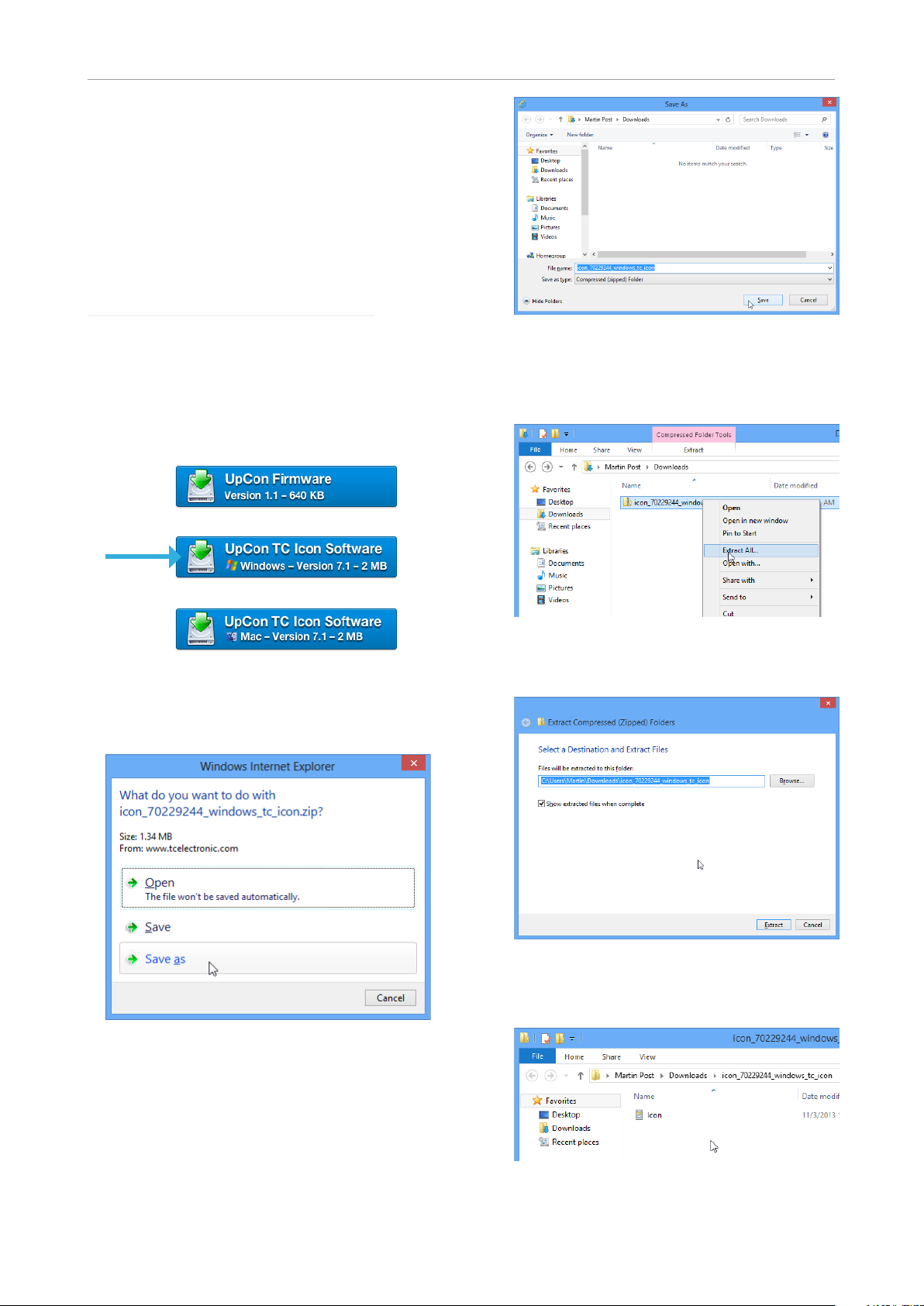
“TC Icon software” and click the button representing the latest version of the TC Icon software for Microsoft Windows.
Depending on your browser type and con-
figuration, a dialog may be shown asking you
what you want to do with this file.
– Go to the folder containing the ZIP file you just
downloaded.
– Right-click the .ZIP file and choose “Extract
All…“ from the context menu.
A dialog box will allow you to specify where
the extracted files should be stored.
Accept the defaults or change the path.
– After extracting the ZIP file, you will see a
Choose “Save”.
The software will be downloaded to your
browser’s default download location. Usually,
this is the “Downloads” folder for your user account.
4 UpCon
.CAB (“Cabinet”) file in Windows Explorer.
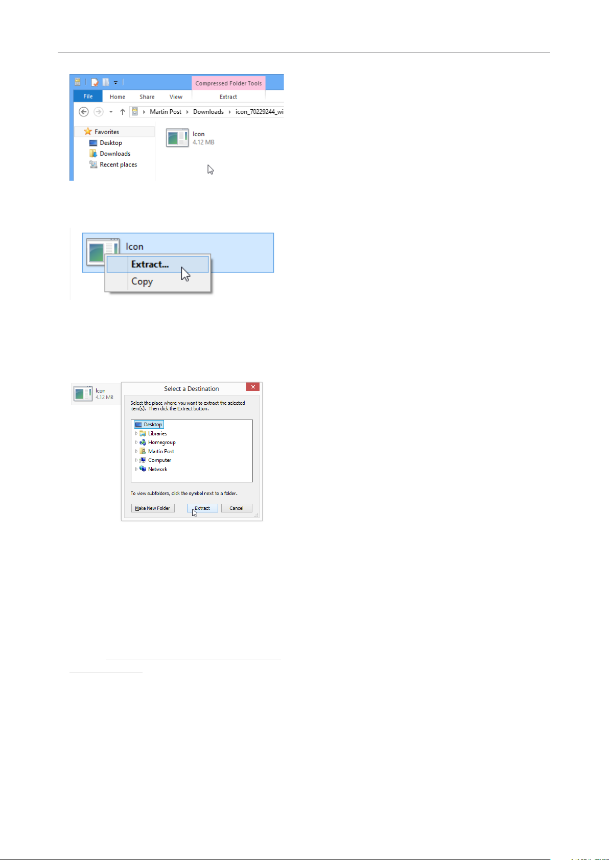
– Double-click the .CAB file.
An “Icon” application file will be shown.
Page 9
Software: TC Icon and UpCon firmware
Updating TC Icon software
To update the TC Icon software on your PC when
a newer version is released,
– quit the TC Icon software if it currently running
on your PC,
– download and extract the newer version as
described in this section and
– Right-click the “Icon” application file and
choose “Extract…“ from the context menu.
In the dialog box that is shown next (“Select
destination”), select a folder where you can
easily find the application – e.g., the Windows
desktop.
– replace the currently installed version by copy-
ing the newer version over it.
– Click “Extract” to extract the application to the
selected destination.
– Launch the TC Icon application that you just
extracted by double-clicking its icon.
TC Icon will try to establish connections to all
connected TCdevices on a local network, including your UpCon.
If a connection cannot be established, please
refer to “Networking basics and troubleshooting” on page 13.
If you experience technical problems during
software download or installation, please ask a
person with administrator privileges on this computer for assistance.
English Manual 5
Page 10
Software: TC Icon and UpCon firmware
Finding and installing
TCIcon software – OSX
The most current version of TC Icon software for
OSX at the time of production is provided on the
USB stick that came with your UpCon, but you
may want to download the latest version from
the TC Electronic website.
You can download the latest version of TC Icon
software for OSX from:
www.tcelectronic.com/support/software/
– On this page, locate the “UpCon” section.
– In this section of the support page, look for
“TC Icon software” and click the button representing the latest version of the TC Icon software for OS X.
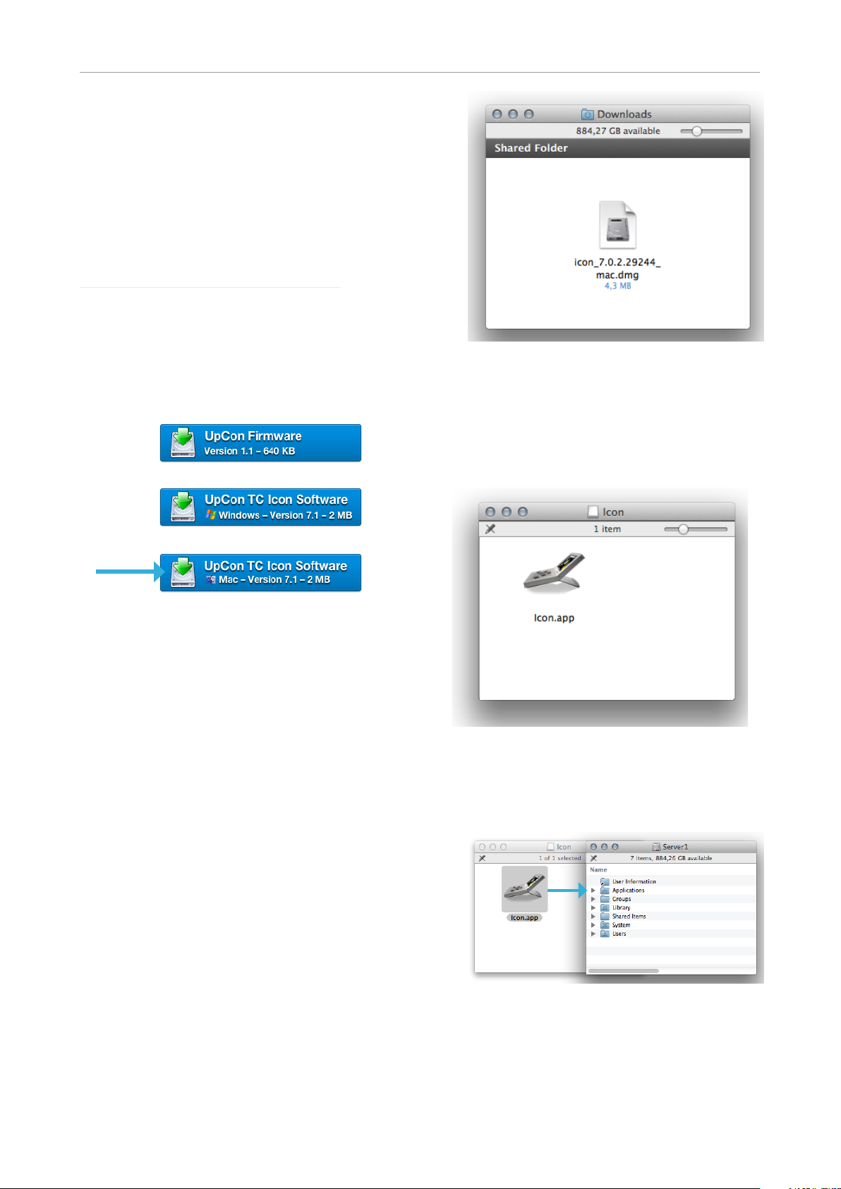
– After the ZIP file has been extracted, you will
see a .DMG (“Disk Image”) file in the Finder.
– Double-click the .DMG file to mount this disk
image.
An “Icon” disk image containing an “Icon” app
will be shown.
Depending on your browser type and con-
figuration, a dialog may be shown asking you
what you want to do with this file. Choose
“Save”.
The software will be downloaded to your
browser’s default download location. Usually,
this is the “Downloads” folder for your user account.
– Go to the folder containing the file you just
downloaded.
– If you are seeing a .ZIP file, double-click it to
extract its contents. However, your browser
may already have extracted the contents from
the .ZIP file automatically.
– Copy the TC Icon application from the disk im-
age to your hard disk by dragging it to the “Ap-
plications” folder, or to another folder where
you can easily find it.
– You can now unmount (eject) the disk image
by right-clicking it and selecting “Eject” from
the context menu.
6 UpCon
Page 11

Software: TC Icon and UpCon firmware
Updating TC Icon software
To update the TC Icon software on your Mac
when a newer version is released,
– quit the TC Icon software if it currently running
– Launch TC Icon by double-clicking the appli-
cation.
TC Icon will try to establish connections to all
connected TCdevices on a local network, including your UpCon.
If a connection cannot be established, please
refer to “Networking basics and troubleshooting” on page 13.
If you experience technical problems during
software download or installation, please ask a
person with administrator privileges on this computer for assistance.
on your Mac,
– download and extract the newer version as
described in this section and
– replace the currently installed version by copy-
ing the newer version over it.
English Manual 7
Page 12

UpCon: An introduction
UpCon: An introduction
conversion from stereo to 5.1, you can stay compliant – regardless of the signal’s channel format.
Thank you for choosing UpCon.
UpCon is a state-of-the-art upconverter that
gives you absolute piece of mind that your transmission is always optimized for 5.1 HD TV.
We have combined uncompromising upconversion and downmix in a single, high-density rack
unit.
UpCon continuously monitors the channel format of the incoming audio – and if the signal falls
back from true 5.1 to stereo, it seamlessly crossfades into a convincing 5.1 surround upconversion without adding any interruptions or artifacts.
Cinema-quality upconversion
UpCon is based on our famous UnWrap HD algorithm, the “go-to” upconverter for film and
mastering professionals that can be heard in
countless cinema movies and music tracks. It
offers the same ultra-low latency and overkill
processing resolution, always delivering unparalleled and convincing 5.1 content from a stereo
source.
Uncompromised Downmix
When you downmix, one of the main factors to
consider is the 5.1 source itself.
Redundancy and reliability
We are aware that UpCon is inserted at a very
critical point in your audio signal path. It’s an “always-on” type of unit that needs to deliver nonstop performance – year after year.
With dual fuses, dual fans and dual power, you
are virtually risk-free of losing power while on
air. And in the unlikely event of the UpCon losing
power, rest assured that your transmission will
go on – thanks to the Relay Bypass feature that
passes your stream directly from input to output,
no matter what happens. And if one of the power
sources fails, you can be notified using GPIO or
SNMP traps.
Operating UpCon
As you can easily see, UpCon is a „headless
system“ – it has no front panel controls (with the
exception of the Reset button).
UpCon is operated using the TC Icon software,
which you can download from the TC Electronic
website.
You can use the same version of the TC Icon
software to operate UpCon and other professional broadcast products from TC Electronic
(e.g. DB4 and DB8MKII).
A 5.1 signal generated by UpCon translates better into stereo than one made by any competing
upconverter – regardless of whether you let UpCon handle the downmix or if it happens at the
end-listener’s TV set. This is essential to broadcasters that generally transmit 5.1 signals, but
receive commercials in stereo, or air newscasts
relying on signals coming in from around the
world - some in 5.1 and others in stereo.
In short: With UpCon in your signal chain, your
downmix will be optimized – no matter what.
Loudness Transparency
In terms of perceived loudness compared to the
source, many format converters will output a significantly different signal. But this is not the case
with UpCon - the upconverted audio is loudness
transparent.
Broadcasters often need to stay within certain
boundaries according to regulations or recommendations, and by letting UpCon handle the
Accordingly, a significant part of this manual
covers operating UpCon using TC Icon software
running on a standard computer, and the screen
shots you see are taken from the OSX or Windows versions of this software.
Please invest some time in learning TC Icon’s
basic concepts – you will benefit from it when
operating systems that may include many networked TC signal processors.
Expanding UpCon
UpCon comes with the ability to process one
stream right out of the box, but users can install
one or two additional 3G Transmission cards.
3G Transmission cards
Each 3G Transmission card can process one
SDI audio stream. Accordingly, an UpCon with
two extra 3G Transmission cards can handle
three independent streams – making it the
perfect high-density solution for any TV station
8 UpCon
Page 13

UpCon: An introduction
in need of processing multiple streams simultaneously.
Instructions on upgrading a base UpCon
with one or two Transmission 3G cards are
not part of this manual. They are provided in
a separate document that comes with the 3G
Transmission card.
UpCon presets
UpCon comes with ready-to-use presets based
on international standards. More presets will be
made available as part of software updates, and
from the TC website. These presets are based
on information from broadcasters around the
world.
If you feel that an important preset is missing or
that a given preset does not work as it should,
please get in touch with TC Electronic technical
support.
Serial digital interface (SDI)
With regards to inputs and outputs, UpCon is
based on the Serial digital interface (SDI) – a
family of audio and video interfaces standardized by the Society of Motion Picture and Television Engineers (SMPTE).
be remote-controlled from an SNMP applica-
tion.
– True redundancy: No compromise, long term
field-tested PSUs. Dual inlets, dual fuses, dual
fans.
– Up to 24 audio channels simultaneously
processed and measured: With a fully load-
ed UpCon, up to 24 audio channels can be
processed simultaneously.
– 100BaseT Full-Duplex Ethernet: Standard
Ethernet control allows easy system integra-
tion. A second port is available for daisy-
chaining, allowing a high number of units on
one network.
– Bit transparent: Supports coded transmis-
sion like Dolby E or Dolby AC3.
An SDI signal may contain up to sixteen audio
channels (8 pairs) at 48kHz sample rate and 24
bit resolution. We assume that you have a good
working knowledge of SDI. The standard as such
is not discussed in this manual.
UpCon features overview
– Audio at its finest: 24 bit transparent, fully
synchronous I/O, 32 bit and higher internal
processing.
– Automatic 5.1 detection: Automatically de-
tect and engage upconversion and down-mix.
– Ultra-low latency: No need for frame offset.
– Always have 5.1 and stereo: Regardless if
the input is 5.1 OR stereo, you can always
have 5.1 and stereo on the outputs.
– Artifact-free: Artifact-free crossfade between
bypass and upconversion.
– GPIO and SDI metadata: Engage format
conversion using GPIO or SDI metadata.
– SD/HD/3G SDI, Relay Bypass: Supports
latest SDI standards, up to 3G: 2.97 mBit/s,
1080p, 3D(2x1080i). Auto relay bypass.
– SNMP (Simple Network Management Pro-
tocol): SNMP trapping lets UpCon send out
messages (such as warnings) over Ethernet to
an SNMP application. Vice versa, UpCon can
English Manual 9
Page 14
Getting to know UpCon
Getting to know UpCon
This section of the manual describes the device’s status indicators and connectors.
! Please note that additional status information
can be displayed using TC Icon software –
see “Obtaining UpCon status information” on
page 20.
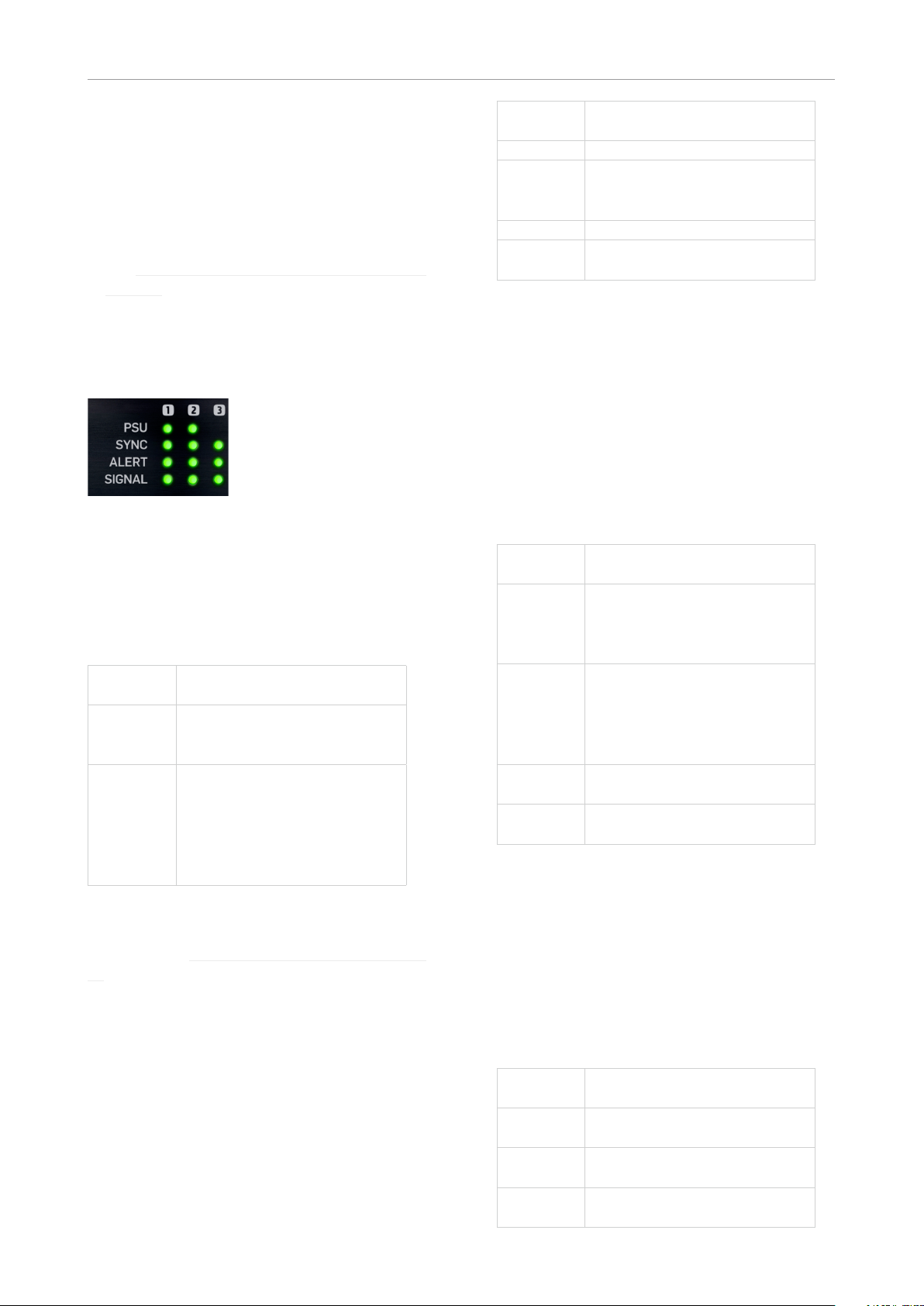
Front panel indicators
UpCon has the following front panel status indicators:
Front panel indicators on UpCon
PSU 1 and PSU 2 LEDs
The PSU 1 and PSU 2 LEDs indicate the status
of the two built-in power supplies.
LED co lor /
indication
Green An external power is connect-
Red There is a problem with the
Please refer to the descriptions of the PSU connectors in the “Back panel connectors” on page
11 section for more information.
Sync LED(s)
UpCon has three Sync LEDs – one for each of
the up to three cards/engines in the device. If
only one card is installed, only the first LED will
be used.
The Sync LEDs indicate if synchronization to
the currently connected signal source has been
achieved.
Status
ed and the power supply is fully functioning.
power supply. Either there is
no external power connected,
or there is a problem at certain checkpoints in the relevant
power supply.
LED co lor /
indication
Off Startup – no lock achieved.
Green An SDI stream has been detect-
Yellow There is an SDI anomaly.
Red UpCon cannot lock to the SDI
Status
ed at the corresponding input,
and UpCon is locked to it.
audio stream.
Alert LED
UpCon has three Alert LEDs – one for each of
the up to three cards/engines in the device. If
only one card is installed, only the first LED will
be used.
The Alert LEDs indicate problems either within
the device or with the signal being processed.
Detection for the Alert LEDs and GPO occurs at
the UpCon’s input.
LED co lor /
indication
Off UpCon is not connected to a
Green UpCon is connected to a com-
Green –
blinking
Yellow There has been silence for
Status
computer running the TC Icon
software or a hardware TC
Icon.
puter running the TC Icon software or a hardware TC Icon.
Normal operation, no problems
detected.
Preset recall
more than five seconds.
Signal LED
UpCon has three Signal LEDs – one for each of
the up to three cards/engines in the device.
The Signal LEDs indicate if audio streams are
received and processed by UpCon. Detection
for the Signal LEDs and GPO occurs at the UpCon’s input.
LED co lor /
indication
Off No audio signal (above
Green An audio signal above
Yellow An audio signal above -1dBFS
Status
-70dBFS) has been detected.
-70dBFS has been detected.
has been detected.
10 UpCon
Page 15

Getting to know UpCon
Front panel reset button
The Reset button on the front panel can be used
to reset the IP address of a UpCon unit or to
reset Ethernet communication between UpCon
and a computer when a communication error
has occurred.
Resetting the IP address
of a UpCon unit
It may be necessary to reset the IP address of a
UpCon unit. To do so, proceed as follows:
– Switch off UpCon by disconnecting both pow-
er supplies.
– Insert a straightened paper clip or a similar
object into the “Reset” hole on the front panel
until it touches the button behind the panel.
– Boot the UpCon by connecting one or both
power supplies while still holding the straight-
ened paper clip onto the Reset button.
UpCon will boot using its default IP address.
The default IP address is 192.168.1.[xx], where
[xx] is the last two digits of the device’s serial
number as printed on its back.
Resetting Ethernet communication
It may be necessary to reset Ethernet communication between UpCon and a computer during
operation. To do so, proceed as follows:
– During operation, insert a straightened paper
clip or a similar object into the “Reset” hole
on the front panel until it touches the button
behind the panel, and press the button for
approximately 5 seconds until the LEDs start
blinking.
This will reset Ethernet communication with-
out interrupting audio streams.
Back panel connectors
UpCon back panel connectors
If possible, connect these two power sockets to
two independent power sources to minimize the
risk of power loss.
Due to the redundant design, UpCon will still be
fully operational when one of the two power supplies fails. However, to ensure maximum security
and stability, you should address the issue and
investigate the cause of the error indication at
the first given opportunity.
In case of complete power loss, the device is
hardware-bypassed via relays, ensuring that no
signal loss occurs.
Ethernet (2 x / 6 x)
UpCon is equipped with 32 bit Ethernet interfaces fully compliant with the IEE 802.3u standard, supporting 10 and 100 Mbit/s (100Base-TX
ports).
UpCon has either two, four or six Ethernet ports
– depending on the number of 3G Transmission
cards installed.
Connect a computer running TC Icon software
or a hardware TC Icon device to one of these
ports using a “straight-through” cable with 8P8C
modular connectors (“RJ45”). A “crossover” type
cable is not required.
The Ethernet ports are used exclusively for connecting a controller (namely a computer running
TC Icon software). No audio signals are transmitted for processing over Ethernet ports.
SDI In Port(s) – (1 / 3)
UpCon has either one, two or three SDI In ports,
depending on the number of 3G Transmission
cards installed.
Connect the upstream SDI device to an SDI
In socket on UpCon. Use a coaxial cable with
BNC connectors with a nominal impedance of
75 Ohms.
SDI Out Port(s) – (1 / 3)
PSU (2 x)
UpCon has two C13 type power inlet sockets.
The dual power inlets provide extended operational security and stability. They accept 100 to
230 Volts AC at 50/60Hz.
English Manual 11
UpCon has either one, two or three SDI Out
ports, depending on the number of Transmission
3G cards installed.
Connect the downstream SDI device to an SDI
Out socket on UpCon. Use a coaxial cable with
Page 16

Getting to know UpCon
BNC connectors with a nominal impedance of
75 Ohms.
GPIO Port(s) – (1 / 3)
Connect a controller to this port to control various UpCon features remotely.
Scenes, Routings, Engines
UpCon offers considerable flexibility in routing,
and processing audio signals. To benefit from
this flexibility, you need to understand the basic
concepts and building blocks of the device as
outlined in this chapter.
Scenes
A Scene is the most extensive selection you can
make when recalling, storing or deleting settings.
A Scene includes…
– all settings for both Engines on a processor/
card
– signal routings to and from these Engines.
Recalling (Loading), storing (saving) and deleting Routing Presets is covered in the “Recalling,
storing and deleting settings” on page 26 section of this manual.
Recalling a Scene is equivalent to a “total recall.”
All the settings that make up a Scene are called
a Scene preset.
Recalling (Loading), storing (saving) and deleting
Scene Presets is covered in the “Recalling, storing and deleting settings” on page 26 section
of this manual.
Engines
Instead of recalling or storing a full Scene as described in the previous section, you may want to
edit, store or recall the settings for one particular
Engine.
All the settings for one particular Engine are
called an Engine preset.
Recalling (Loading), storing (saving) and deleting
Engine Presets is covered in the “Recalling, storing and deleting settings” on page 26 section
of this manual.
Routings
All the settings that define how signals are routed to and from the Engines on a processor/card
are called a Routing preset.
12 UpCon
Page 17

Setting up UpCon
Subnet mask and TCP/IP addresses
Setting up UpCon
UpCon can be used in a variety of configurations
and setups. However, as all TC Broadcast processors in your system can be controlled from a
single computer running TC Icon software, even
large and complex setups are basically operated in the same manner as the basic setup described in this chapter.
Networking basics and
troubleshooting
You may setup and operate your UpCon in a
simple networking environment – where you can
connect a computer and one UpCon directly using a standard Ethernet cable –, or your system
may be more complex, involving several computers, several UpCon and other TC devices.
Either way, you are operating a system based on
TCP/IP – the same protocol suite the Internet is
built on. Accordingly, you need to follow basic
networking procedures when setting up your
system.
It is absolutely possible that a standard computer running the TC Icon software will detect a UpCon “out of the box” without problems. However,
if it doesn’t, there is most likely a subnet issue
or an IP address conflict. In this case, please
refer to the following sections.
The subnet mask is a number that defines a
“group” of computers (or other devices) connected to a network. All units in this group must
have the same subnet mask.
The default subnet mask of each UpCon is
255.255.255.0.
The TCP/IP address of each device connected to a network has to be unique. An IP ad-
dress consists of four decimal numbers (ranging
from 0 to 255) separated by dots, e.g. 192.168.1.1
The first three numbers (e.g. “192.168.1”) must
be the same for each unit – but the remaining
number has to be unique in the subnet. I.e., no
two units in the subnet can have the same last
number.
The default IP address of each UpCon is
19 2 .16 8.1.[n n],
…where [nn] is identical to the last two digits in
the UpCon’s serial number (you will find the serial number of UpCon on a label on the rear side
of the device). This way, multiple UpCon’s can
be setup directly out of the box without having
to change their IP numbers.
If your computer is using the same IP address
as a UpCon on the same network, you have two
options:
– Alter the last octet (the last three numbers) of
your computer’s IP address or
– Alter the last octet of the UpCon’s IP address.
English Manual 13
Page 18

Setting up UpCon
Changing your computer’s subnet
mask and TCP/IP address
If and where you can change the subnet mask
and IP address of your computer depends on…
– the operating system you are using and
– your account privileges.
In case of doubt, please consult your company’s
network administrator.
To find and change the TCP/IP
address and the subnet mask on
a computer running Windows:
– G o to Control Panel / Net work Connectio ns / In-
ternet Protocol (TCP/IP).
– Set the TCP/IP address.
To find and change the TCP/
IP address and the subnet mask
on a computer running OSX:
– Go to System Preferences / Network.
– Select “Ethernet”.
– Under “Configure IPv4”, select “Manually”.
– Set the TCP/IP address.
OSX Network preferences
For further information, please refer to you operating system’s integrated help system.
14 UpCon
Page 19

Setting up UpCon
Changing subnet mask and
TCP/IP address of a UpCon
To change the subnet mask and TCP/IP address
of a UpCon, you need to access it using a computer running the TC Icon software. This means
that in case of an IP address conflict that keeps
you from accessing UpCon in the first place, you
need to change your computer’s IP first as described in the previous section.
– Launch the TC Icon software on your comput-
er.
– Select the particular UpCon you want to ac-
cess.
– Click on the Frame tab.
– Select the System page.
– Select the Setup subpage.
– Select Net.
To change the IP address:
– Select the IP address parameter.
– Enter the new IP address.
– Confirm by clicking Enter.
To change the subnet mask:
– Select the IP Subnet Mask parameter.
– Enter the new subnet mask.
– Confirm by clicking Enter.
Resetting the IP address of a UpCon
You may need to reset the IP address of a UpCon. This procedure is described in the section
“Front panel reset button” on page 11.
If the serial number of a particular UpCon ends
with “00”, the default IP address for this device
will be 192.168.1.100, as “00” is not a valid IP
number in all networks.
There is a small risk that two UpCon (or other TC
signal processors) on a network have the same
last two digits in the serial number and thus will
conflict after a reset. To resolve this issue, reset
one UpCon first and change its IP address before connecting the second UpCon.
Quick Setup
This guide applies for a simple setup as illustrated below.
Ethernet
connection
Requirements for this setup are:
– UpCon
– CAT5 Ethernet cable
– Computer equipped with an Ethernet adapter,
running Microsoft Windows or Mac OSX and
the latest version of TC Icon software.
Proceed as follows:
– Unpack UpCon and mount in a well-ventilated
space.
– Connect UpCon and your computer using an
Ethernet cable.
– Power up your computer and UpCon.
– If you have not already done so, download and
install the latest version of the TC Icon soft-
ware editor on your computer.
– Launch the TC Icon software on your comput-
er.
The following screen will appear:
– Click “Assign”. The network is scanned, and
all connected and operational devices will be
listed on the next screen.
English Manual 15
Page 20

Setting up UpCon
– Select the device you wish to access.
– If you cannot access UpCon, please refer to
“Networking basics and troubleshooting” on
page 13.
That’s it – you are now ready to configure and
operate your UpCon.
Updating UpCon software
The latest version of both the UpCon software
and the TC Icon software editor available at the
time of production are supplied with your UpCon.
However, from time to time, software updates
are made available by TC, containing both bug
fixes and new features.
Please download and install the most current
version of the TC Icon software from:
www.tcelectronic.com/support/software/
The TC Icon software is available for
– Microsoft Windows and
– Mac OSX.
Using TC Icon software, you can access your
UpCon and update its built-in software (the firmware), which is provided as a separate download.
Updating UpCon firmware is described in “Updating UpCon firmware” on page 28.
16 UpCon
Page 21

Basic operation
Basic operation
Introduction
This section of the manual is a general introduction to operating UpCon using the TC Icon software.
In the following chapters we assume that you
have connected UpCon and your computer directly or as part of a network as described in
“Setting up UpCon” on page 13.
Several UpCon and other TC signal processors
(e.g. DB4/DB8MKII), and computers running the
TC Icon software can be connected and operated at the same time as part of a standard Local Area Network (LAN). The TC Icon software is
used to detect, configure and operate devices
from your computer.
If you encounter communication errors or cannot
detect or operate a device properly, please refer
to “Networking basics and troubleshooting” on
page 13.
Basic TC Icon operation
The TC Icon software interface has been optimized for use in real-time situations in broadcast
and post production environments (which usually are very different from standard desktop computing tasks and environments). Accordingly,
buttons are very prominent and clearly labelled
to ensure proper operation even in stressful situations. In addition, important parameters can be
assigned to on-screen faders, allowing for precise control and immediate visual feedback.
The interface can be customized. Customizable
parameters include fader positions and user interface colors. For more information, please refer
to the chapters ““UI page” on page 34” and
“Color page” on page 34 of this manual.
TC Icon interface: Tabs versus pages
– Use the tab buttons on the upper edge of the
TC Icon window to select a primary group of
functions.
– Use the page buttons on the left edge of the
TC Icon window to select specific pages.
TC Icon modes: Base and
Device operation
The TC Icon software has two operation modes:
Base and Device operation.
– Use Base mode to select devices and con-
figure the network and the TC Icon software
itself.
In Base mode, you will see the Select, Auto
and Setup tabs on the upper edge of the TC
Icon window. Most Base mode functions are
described in the chapter “Icon Setup” on page
33.
– Use Device operation mode to operate the
currently selected device.
In Device Mode, you will see the specific tabs
for operating the currently selected TC device.
Switching between Base and
Device operation modes:
– To switch between Base and Device operation
modes, click the Icon symbol in the upper left
corner of the window.
Faders
The TC Icon software has large on-screen faders. They have several features that will help you
operate your UpCon efficiently.
– There are six on-screen faders.
– You can change the position of the faders or
hide them completely – see“UI page” on page
34.
– The name of the parameter that a fader is cur-
rently assigned to is displayed above the fad-
er.
– When no label is shown above a fader, that
fader is currently not assigned to a parameter.
– Fader assignments and values will always re-
flect the last Engine you have accessed.
Using Faders for fine adjustments
When a parameter is assigned to a fader, you
can choose between Normal and Fine adjust-
ment mode.
– In Normal Adjustment mode, the fader range
will cover the full parameter range – e.g.
-18dB to 18dB for the Center Trim parameter.
– In Fine Adjustment mode, the fader range
will be smaller, allowing you to fine-tune
around the current value – e.g. in 0.1dB steps
for a level parameter.
To switch a fader from Normal Adjustment mode
to Fine Adjustment mode or back, click the label
English Manual 17
Page 22

Basic operation
above that fader. Fine Adjust mode will be indicated by two triangles in the label field.
Fader label indicating Fine adjustment mode
Fader Groups
UpCon algorithms encompass many parameters
on several pages. For efficient operation, the
most important parameters can be assigned to
the on-screen faders in Fader Groups. Fader
Groups allow you to access the most important
features immediately, no matter what particular
page is currently being displayed.
Fader group 1 selected in the
Fader Group selector
– Use the arrow buttons on the Fader Group se-
lector to select the “User” Fader Group.
– Click the “Fader Asgn” button (on the left edge
of the TC Icon software window).
– Click the label of a fader that you want to as-
sign to a parameter.
– Click the name of the parameter that you want
to assign to the previously selected fader.
– Repeat the last two steps until you have made
all desired assignments.
– Click the “Fader Asgn” button again.
Assigning Fader 6 on the fly
Even when using one of the predefined Fader
Groups for an Engine, you can always assign the
sixth Fader to whatever parameter you want to
control in a given situation. Like all other Faderrelated settings, this is an Engine-specific setting: You can assign Fader 6 to one parameter
when Engine 1 is selected and to another parameter when Engine 2 is selected.
To assign a parameter to fader 6:
– To assign a parameter to the fader 6, simply
click on a parameter field. That parameter will
immediately be assigned to the sixth fader. If
that parameter is also assigned to one of the
other faders, you can now use both faders to
control that parameter.
You can access predefined Fader Groups that
cover typical applications, and you can define a
User Fader Group with your own assignment for
each fader.
You can select and customize Fader Groups per
Engine – meaning that you can use one group of
fader assignments for Engine 1, and another one
for Engine 2.
To select a Fader Group:
– Select the tab of an Engine (on the top edge of
the TC Icon software window).
– Use the arrow buttons on the Fader Group se-
lector (on the left edge of the TC Icon software
window) to select the desired Fader Group.
The name of the currently selected Engine
and Fader Group are displayed on the Fader
Group selector. E.g., “E1 Group 1” means that
you have selected the predefined Fader Group
1 for Engine 1.
To set up the User Fader Group:
– Select the tab of an Engine (on the top edge of
the TC Icon software window).
On-screen keyboard
UpCon allows you to store and rename presets,
assign labels to inputs and outputs and perform
other functions where text input is required.
When you access one of these functions, an onscreen keyboard will be displayed.
TC Icon software – On-screen keyboard
While they keyboard is being displayed, you can
either click the letters shown on-screen or use
your computer’s keyboard for character input.
When you are done, click the large Enter button
or press your computer keyboard’s Enter key.
18 UpCon
Page 23

Accessing UpCon
In the following sections of this manual, we as-
Accessing UpCon
– Connect your computer and UpCon as de-
scribed in the “Setting up UpCon” chapter.
– Power up your computer and your UpCon.
– On your computer, launch the TC Icon soft-
ware.
– When you do this for the first time or the sys-
tem configuration has been changed, the fol-
lowing screen will appear:
sume that you are operating a basic system with
only one UpCon connected.
– Click “Assign”.
– All currently connected TC signal processors
that are supported by the TC Icon software
should be detected and assigned to one of the
8 on-screen slots/locations.
– If a connected device is not detected, please
refer to “Networking basics and troubleshoot-
ing” on page 13.
– Click the icon representing the UpCon to ac-
cess it.
Scanning / rescanning a
network for devices
The scenario described above covers the first
time you boot up your system or when no connected units are assigned.
When…
– you make changes to your setup,
– when devices are powered up or down, or
– if there are connection errors, these may not
be detected immediately.
In this case, you should scan the network again.
To scan a network for devices:
– In the TC Icon software, go to Setup / Devices
– Click the Detect button.
For further information, see “Devices page” on
page 33.
English Manual 19
Page 24

Obtaining UpCon status information
Obtaining UpCon
status information
Please note that the LEDs on the front of a UpCon will display basic status information as long
as the device is powered – see “Front panel indicators” on page 10.
A power supply failure may be indicated as described in the following section.
Sync indicator
The states and color codes shown here are the
same as those shown by the respective UpCon
Sync LED – see “Sync LED(s)” on page 10.
Additional status information can be displayed
using TC Icon.
To display status information about UpCon, go to
Frame / System / Status.
This page will display the following status information:
Clock section
Alert indicator
The states and color codes shown here are the
same as those shown by the respective UpCon
Alert LED – see “Alert LED” on page 10.
Signal indicator
The states and color codes shown here are the
same as those shown by the respective UpCon
Signal LED – see “Signal LED” on page 10.
Power Warning parameter
A failing supply is always indicated by a red LED
on the front panel. TC Icon can also indicate a
failing power supply, depending on the setting of
the “Power Warning” parameter.
“Off” setting
A failing power supply is not reported in the Icon
remote app.
Source indicator
Indicates the source of the clock signal UpCon is
currently following.
Lock indicator
Indicates wether synchronization has been
achieved. If no synchronization has been
achieved, a red LED will be shown in this field.
Sample Rate indicator
Shows the detected sample rate of the signal
UpCon is synced to.
Status section
Power indicator
Displays the current state(s) of the power supplies UpCon is connected to.
“Warning”setting
A failing power supply is indicated by a yellow
“Power” label in the respective UpCon Frame indicator, and a yellow LED will show on the Frame
tab when it is selected.
“Error” setting
A failing power supply is indicated by a red
“Power” label in the respective UpCon Frame
indicator, and a red LED will show on the Frame
tab when it is selected.
Temperature indicator
Shows the current internal temperature of UpCon.
20 UpCon
Page 25

Setting up audio
Audio Groups selector
Setting up audio
To set up au dio, go to Frame / System / I/O / SDI.
Use this page to display information about incoming audio, select audio for processing and
change Advanced SDI settings.
Use the Audio Groups selector to select audio
groups for metering and processing. Available
settings are “Groups 1+2” and “Groups 3+4”.
! Please note that the UpCon always receives
two of the audio groups in the incoming
stream. The unprocessed audio groups are
bypassed bit-transparently, as well as all related SDI packets such as video time code,
close captions etc.
Advanced SDI Mode section
The Advanced SDI Mode section contains SDIrelated settings that you would normally not have
to change.
Advanced settings switch
To change Advanced SDI settings, click the Advanced button in the Advanced SDI Mode sec-
SDI Status indication section
tion of this page.
Lock status indicator
The Lock status field shows the top level status
of lock to an incoming SDI stream. When UpCon
is locked to an acceptable SDI stream on the SDI
input, “Lock” is shown. When no acceptable SDI
stream is available on the SDI input, “No Lock”
and a red LED will be shown in this field.
Format indicator
When the UpCon is locking to an incoming SDI
stream, the Format indicator field will show the
format – e.g. “1080i59.94 HD”. If the UpCon is
not locking to any incoming SDI stream, the Format indicator field will read “N/A”.
Available Groups indicators
SDI with embedded audio carries up to 16 channels of audio, divided into four groups. Accordingly, each group carries four channels of audio.
The four Available Groups indicators what audio
groups are available in the incoming SDI stream
for metering and processing. The on-screen LED
for each available group will light up in green.
If the UpCon is not locking to an incoming SDI
stream, all indicators are turned off.
! Please note that switching off access to Ad-
vanced SDI settings will reset all parameters
in this section to their default values.
Clock Mode parameter
With SDI standards constantly evolving, chances are that upstream equipment treat audio and
video sync differently – e.g., a device may only
pay attention to one or the other. As this may
cause occasional disruption of sound, picture or
both, a problem may be difficult to trace without
measurement equipment monitoring SDI traffic for weeks or months. To diagnose a potential problem, UpCon offers a diagnostic mode,
which may be tried after consulting TC support.
To activate diagnostic mode, set the Clock Mode
parameter to Diagnostic.
In Diagnostic mode, the UpCon will disregard
the audio clock information included in the audio
packets in the SDI stream and de-embed the audio based on the video clock only.
! Use the Diagnostic setting for diagnostic pur-
poses only.
Audio Out Groups parameter
Use the Audio Out Groups parameter to define if
and how the group assignment of the processed
audio signals should be changed.
English Manual 21
Page 26

Setting up audio
Follow In Group setting
The processed audio signals will be assigned to
the same audio channel groups at the SDI output that were selected using the Audio Groups
selector. This is the default setting which is also
used when Advanced SDI mode has not been
activated.
Group 1+2 and Group 3+4 settings
The processed audio signals will be assigned to
the audio channel groups 1 and 2 or groups 3
and 4 at the SDI output.
If you are using this parameter to reassign audio
channels to other groups, make sure that you are
processing the right audio groups downstream.
Rate Detect Mode parameter
Use the Rate Detect Mode parameter to specify
how UpCon should behave when receiving SD,
HD and 3G signals. By narrowing the range of
formats acceptable to the UpCon, lock-up time
may be optimized.
select the stream that UpCon should de-embed/
embed audio from and to.
! Please note that when running 3G Level B,
data stream 1 and data stream 2 need to have
the same bit width so UpCon can de-embed
and process audio. I.e., both data streams
need to contain 8-bit data, or both data
streams need contain 10-bit data). If the bit
widths of the two data streams differ, UpCon
will not be able to de-embed and process audio.
Stream 1 setting
The UpCon will de-embed and embed two of
the up to four available audio groups in stream
1. This is the default setting which is also used
when Advanced SDI mode has not been activated.
Stream 2 setting
The UpCon will de-embed and embed two of
the up to four available audio groups in stream 2.
Automatic setting
When you set the Rate Detect Mode parameter
to Automatic, UpCon will accept all SDI formats:
SD, HD and 3G. This is the default setting which
is also used when Advanced SDI mode has not
been activated.
SD only setting
When you set the Rate Detect Mode parameter
to SD, UpCon will only accept the SD format and
not consider locking to HD or 3G signals. This results in optimal lock-up time for SD signals.
HD only setting
When you set the Rate Detect Mode parameter
to HD, UpCon will only accept the HD format and
not consider locking to SD or 3G signals. This results in optimal lock-up time for HD signals.
3G only setting
When you set the Rate Detect Mode parameter
to 3G, UpCon will only accept the 3G format and
not consider locking to SD or HD signals. This
results in optimal lock-up time for 3G signals.
Bypass Option parameter
Use the Bypass Option parameter to enable
manual overwrite of the SDI hardware bypass
relay. This option is useful for diagnostics purposes.
If the Bypass option is enabled, a Bypass button
will be shown in the Advanced SDI Mode section. Clicking the Bypass button will immediately
activate a hardware bypass of the SDI signal, allowing it to pass through UpCon unprocessed.
If you set the Bypass Option parameter to disabled, the SDI bypass relay can not be overwritten manually.
Setting up audio dithering
To set up audio dithering, go to Frame / System / I/O / Dither.
Stream 3G LevelB selection parameter
With 3G Level B SDI (SMPTE424M), 32 audio
channels in 8 audio groups are available via two
Use the Dither page to set up if and how audio
signals should be dithered.
streams. Use the Stream 3G LevelB parameter to
22 UpCon
Page 27

Setting up audio
Dither out parameters
Use the four Dither out parameters (1/2, 3/4, 5/6,
and 7/8) to configure dithering for each pair of
audio signals. Available settings are “Off” (no
dithering applied), 24 bit, 20 bit, 18 bit and 16 bit.
! If you are handling data-reduced formats, be
sure to set these parameters to “Off”.
English Manual 23
Page 28

Setting up GPI/O
Setting up GPI/O
Setting up GPI
To set up GPI, go to the Frame / System / GPI/O / GPI page. Use this page to configure GPI operation.
UpCon GPI page
UpCon GPI calibration page
Each GPI may be used to switch between up to
8 states. GPI calibration should be performed
when switching between more than two states
(as it is required for preset recall).
UpCon includes four multi-state GP inputs used
to signal…
– preset change,
– content data,
– meter functions and
– logging functions.
The famous multi-state functionality inherited
from DB4 and DB8 makes use of precise voltage
windows to define which function is selected. Error-free operation is ensured by a refined window
detection algorithm.
GPI 1: Preset Recall
GPI 1 enables switching between 2, 3, 4, 7, 8 or
16 Scene Presets.
Please note that setting the GPI Preset Recall
parameter to an even number (2, 4, 8 or 16) will
cause UpCon to instantly recall a Scene User
preset of the Bank selected – even if no GP input
signal is applied.
Current section
The Current section of the GPI Calibration page
provides live status information for the GP inputs. Here, “Vs” denotes positive terminal on the
respective GP connector, typically 3.3 V.
Limits section
The Limits section of the GPI Calibration page
shows the lower (“GPI Lo Threshold”) and upper
(“GPI Hi Threshold”) limits of the voltage windows for the four GP inputs.
To calibrate a GPI input, click the respective Calibrate button and follow the on-screen instructions.
Setting up GPO
To set up GPO, go to the Frame / System / GPI/O / GPO page.
Setting the GPI Preset Recall parameter to an
odd number (3 or 7) enables normal operation
and preset recall via Ethernet and the TC Icon
software as long as no GP input signal is applied. However, if GPI 1 is activated, the GP input
selection of preset overrides normal operation.
! More GPI functions will be added with upcom-
ing UpCon software versions.
UpCon GPO page
GP Input Calibration
To calibrate GPI, go to the Frame / System / GPI/O / Cal page.
24 UpCon
Two relay-based general-purpose outputs are
available. Use this page to configure them.
Page 29

Setting up GPI/O
GPO 1 and GPO 2 parameters
Use the GPO 1 and GPO 2 parameters to specify which status information should be transmitted to the GPO pins. Available settings are “Off”,
“Sync LED”, “Alert LED” and “Signal LED”. If you
select one of the three LED options, the selected
GPO pin pair will communicate the status of the
respective UpCon front panel LED.
Idle State 1 and Idle State 2 parameters
Use the Idle State 1 and Idle State 2 parameters
to specify which state of the respective GPO relay (1 or 2) should represent the inactive state of
the assigned LED/status information. Available
settings are “Open” and “Closed”.
GPO setup example
– To signal UpCon Synchronization Status on
GPO relay 1 – see “Sync LED(s)” on page
10 –, set the GPO 1 parameter to “Sync
LED ”.
– If you set Idle State 1 to “Open”, the GPO 1
relay…
– will be open as long as no synchronization
has been achieved and
– will close when synchronization has been
achieved.
English Manual 25
Page 30

Recalling, storing and deleting settings
Recalling, storing and
deleting settings
The Library concept
The Library gives you access to all settings of
all parameters of the currently selected UpCon.
The highest organizational level of the Library is
a Bank. A Bank will hold either…
– 50 Scene presets or
– 50 Routing presets or
– 100 Engine presets.
Factory presets vs. user presets
When recalling presets, you will see that there
are two categories of presets: Factory presets
and User presets.
– Factory presets can only be recalled, but not
overwritten or deleted. If you change a Fac-
tory preset and you want to keep it, you have
to store it as a User preset.
– User presets can be recalled, edited and
stored, thereby overwriting the previous ver-
sion.
Library – Recall page
– Select the “Recall” page.
– Select the subpage for the setting type you
want to access:
– Scene – to recall a Scene preset
– Route – to recall a Routing preset.
– E(ngine) 1 or E(ngine) 2 – to recall an Engine
preset and use it for the currently selected
Engine.
– Select between Factory and User preset
groups by clicking the Factory or User button.
There are 8 Factory and 8 User preset groups,
with each group holding up to 8 presets.
– Select a preset you want to use.
– Click the large “Recall (Sce ne / Route / Engine)
Preset” button in the upper right corner to re-
call (activate) the selected preset.
The selected preset will be recalled.
Preset information
For many presets, additional information is
stored as part of the preset. When you select
such a preset, an inverted “Info” tag will appear
at the bottom of the large Preset Recall button.
– Click the Info tag to display additional informa-
tion about this preset in a modal dialog.
– Click the OK button do close the dialog.
Library – Store page
Library – Preset Recall page
Library – Scene Store page
Use the Library Recall page of the TC Icon software to recall (load) previously stored settings
into the memory of the currently selected device.
All colored buttons and selected items on the
Recall page are colored in green.
To access the Library Recall page:
– If it isn’t already, select the device you want to
control using the Select page – see “TC Icon
modes: Base and Device operation” on page
17.
– Select the “Library” tab.
26 UpCon
Use the Library Store page of the TC Icon software to store (save) settings to a memory bank.
You can only store settings as User presets. Factory presets cannot be overwritten.
All colored buttons and selected items on the
Store page are colored in red.
To access the Library Store page:
– Select the “Library” tab.
– Select the “Store” page.
Page 31

Recalling, storing and deleting settings
– Select the subpage for the setting type you
want to store:
– Scene – to store all settings (including Rout-
ing and all algorithm settings) as a Scene.
– Route – to store the current Routing.
– E(ngine) 1 or E(ngine) 2 – to store the set-
tings of either Engine 1 or 2 as an Engine
preset.
– Select a User preset group.
There are 8 User preset groups, with each
group holding up to 8 presets.
– Select a preset slot in the currently selected
group that you want to use.
– Click the large “Store (Scen e / Route / Engine)
Preset” button to store (save) your settings as
a preset.
The selected data type will be stored as a pre-
set. You can then recall this preset – see “Library – Recall page” on page 26.
Naming Presets
All user preset types can be (re)named.
the large “Store (Scen e / Route / Engine) Preset” button.
Operating the unit while renaming presets
Please note that even when renaming presets
or adding information as described above, the
faders for the previously accessed page are still
available and operational. This means you can
continue operating the faders even when the
keyboard is shown on screen.
Library – Delete page
To rename a preset:
– On the Store page, select the preset that you
want to rename.
– Click the “Name” button.
– An on-screen keyboard will be shown.
– Use the on-screen keys or the physical key-
board of your computer to edit the name.
– Click the large Enter button to confirm the new
name.
! Please note that the preset itself is not stored
when you click the Enter button! To store
the preset with its new name, click the large
“Store (Scene / Route / Eng ine) Preset” button.
Adding Preset Information
You can add information to presets you have
created or modified. When recalling such a preset later, an inverted “Info” tag will appear at the
bottom of the large Preset Recall button, allowing the user to access this additional information
– see “Preset information” on page 26.
To add information to a preset:
– On the Store page, select the preset that you
want to add information to.
– Click the “Info” button.
– An on-screen keyboard will be shown.
– Use the on-screen keys or the physical key-
board of your computer to edit the name.
– Click Enter to confirm.
! Please note that the preset itself is not stored
when you click the Enter button! To store the
preset with the newly added information, click
Library – Scene Delete page
Use the Library Delete page of the TC Icon software to delete settings from a memory bank. You
can only delete User presets. Factory presets
cannot be deleted.
Please note that all colored buttons and selected
items on the Delete page are colored in yellow.
To access the Library Delete page:
– Select the “Library” tab.
– Select the “Delete” page.
– Select the subpage for the setting type you
want to delete:
– Scene
– Route
– E(ngine) 1 or E(ngine) 2
– Select a User preset group.
There are 8 User preset groups, with each
group holding up to 8 presets.
– Select a preset in the currently selected group
that you want to delete.
– Click the large “Delete (Scene / Route / Eng ine)
Preset” button to delete the selected preset.
– You will be asked to confirm this operation be-
fore the preset is actually deleted.
Operating the unit while deleting presets
Please note that even when deleting presets, the
faders for the previously accessed page are still
available and operational. This means you can
English Manual 27
Page 32

Updating UpCon firmware
continue operating the faders even when the
keyboard is shown on screen.
Updating UpCon firmware
Library – Bank page
Use the Library Bank page of the TC Icon software to copy Scene, Routing and Engine Presets from one location to another. You can copy
Scene, Routing and Engine Presets from and to
Banks and files. Files can be transferred to other computers, allowing you to easily reuse your
presets.
To access the Library Bank page:
– If it isn’t already, select the device you want to
control using the Select page – see “TC Icon
modes: Base and Device operation” on page
17.
– Select the “Library” tab.
– Select the “Bank” page.
– Select the subpage for the setting type you
want to copy:
– Scene – to copy Scene presets.
– Route – to copy Routing presets.
– Engine – to copy Engine presets.
To copy from a Bank to a file on disk
– Select “From Bank” in the first column. The
second column will switch to “To File” accordingly.
– Specify the folder where the file should be
written in the “File Folder” field.
– If you want to overwrite an existing file, select
it in the right column. If you select “New file”
instead, you will be prompted to specify the
file name.
– Click the “Copy Bank” button.
You should keep both the TC Icon software
running on your computer and the software
of your UpCon (the firmware) up to date. Us-
ing up-to-date software versions ensures you
benefit from bug fixes and the latest features.
Updating the firmware of your UpCon requires a computer with the TC Icon software
installed. In TCIcon, you can select a previously
downloaded UpCon firmware file (with a “.tca”
suffix) and apply it to the currently selected UpCon.
For downloading, installing and updating TC Icon
software, please refer to
– “Finding and installing TCIcon software – Mi-
crosoft Windows” on page 4 or
– “Finding and installing TC Icon software –
OSX” on page 6.
This section describes downloading and installing the UpCon firmware.
To copy from a file on disk to a Bank
– Select “From File” in the first column. The sec-
ond column will switch to “To Bank” accordingly.
– Specify the folder from where the file should
be read in the “File Folder” field.
– Click the “Copy Bank” button.
28 UpCon
Page 33

Updating UpCon firmware
Finding and installing UpCon
firmware – Microsoft Windows
You can download the latest version of the UpCon firmware from:
www.tcelectronic.com/support/software/
– On this page, locate the “UpCon” section.
– In this section of the support page, look for
“Firmware” and click the button representing
the latest version of the UpCon firmware.
Depending on your browser type and con-
figuration, a dialog may be shown asking you
what you want to do with this file.
– In Windows Explorer, navigate to the folder
containing the ZIP file you just downloaded.
– Right-click the ZIP file and choose “Extract
All…“ from the context menu.
A dialog box will allow you to specify where
the extracted files should be stored.
Choose “Save”.
The software will be downloaded to your
browser’s default download location. Usually,
this is the “Downloads” folder for your user account.
– Accept the defaults or change the path. We
suggest changing the path to “C:\upcon\”.
This will allow you to locate the file in TC Icon
software more easily.
– After extracting the ZIP file, you will see a .tca
file in Windows Explorer.
In the next steps, you will select this .tca file in
the TC Icon software to transfer it to UpCon.
We will assume that you have extracted the
content of the ZIP archive to C:\upcon\. If you
have extracted it to another location, you will
have to specify this in the “Common Software
Update Folder” field accordingly (see below).
– Connect your PC to the UpCon that you want
to update using an Ethernet cable.
English Manual 29
– Launch the TC Icon software on your PC.
Page 34

Updating UpCon firmware
– In the TC Icon software, select the UpCon that
you want to update.
– Go to the Frame / System / Setup / Version
page.
Here, you will find the current software version
of your UpCon (shown as “UpCon SW Version”). Note this version number.
– Go to the Frame / System / Setup / Update
page.
– Click into the “Common Software Update
Folder” field.
– Enter the path to the folder where the down-
loaded .tca file is located.
Example:
Assuming that…
– your hard disk drive has the letter c:\
– you extracted the downloaded .tca file to
the folder “upcon” on the drive root (see
previous steps)
…the correct path would be:
C:\upcon\
Click “OK”.
– Go to the Frame / System / Setup / Version
page and note the updated software version.
! Please note that a folder may contain mul-
tiple .tca files, which will be shown on the
Frame / System / Setup / Update page when
that folder is selected. Be sure to select the
correct file – usually, the most current one.
! If you experience technical problems during
software download or installation, please ask
a person with administrator privileges on this
PC for assistance.
– Click Enter. You will be returned to the previ-
ous screen.
The name of the .tca file you downloaded
should now be displayed right under the
“Common Software Update Folder” field.
– If you want to make sure you have selected
the correct file before applying the update,
you can select the downloaded software file
and click the “File Info” button to display ad-
ditional information.
– To apply the update, select the downloaded
.tca file and click the “Update SW” button.
– Confirm that you want to perform the update
by clicking the “Yes” button.
– A confirmation message will be shown once
the update has been applied.
30 UpCon
Page 35

Updating UpCon firmware
Finding and installing
UpCon firmware – OSX
You can download the latest version of the UpCon firmware from:
www.tcelectronic.com/support/software/
– On this page, locate the “UpCon” section.
– In this section of the support page, look for
“Firmware” and click the button representing
the latest version of the UpCon firmware.
Depending on your browser type and con-
figuration, a dialog may be shown asking you
what you want to do with this file. Choose
“Save”.
The software will be downloaded to your
browser’s default download location. Usually,
this is the “Downloads” folder for your user ac-
count.
– Go to the folder containing the file you just
downloaded.
– If you are seeing a .ZIP file, double-click it to
extract its contents. However, your browser
may already have extracted the contents from
the .ZIP file automatically.
– After the ZIP file has been extracted, you will
see a .tca file in the Finder.
For the first example, we will assume that you
have left the file at its default position (the
“Downloads” folder).
If you have moved the downloaded .tca file
somewhere else, or if you intend to use a .tca
file on a network or USB drive, you will have to
specify the correct path in the “Common Software Update Folder” field of TC Icon software
accordingly (see “Locating the UpCon firmware
file – example 2” on page 32).
– Connect your Mac to the UpCon that you want
to update using an Ethernet cable.
– Launch the TC Icon software on your Mac.
– In the TC Icon software, select the UpCon that
you want to update.
– Go to the Frame / System / Setup / Version
page.
Here, you will find the current software version
of your UpCon (shown as “UpCon SW Ver-
sion”). Note this version number.
– Go to the Frame / System / Setup / Update
page.
– Click into the “Common Software Update
Folder” field.
– Enter the path to the folder where the down-
loaded .tca file is located.
In the next steps, you will select this .tca file in
the TC Icon software to transfer it to UpCon.
English Manual 31
Page 36

Updating UpCon firmware
Locating and transferring the
UpCon firmware file – example 1
This is a simple default scenario where we assume that…
– your hard disk drive is called
“MacintoshHD”
– your (short) user account name in OS X is
“joe” and
– you have not moved the .tca file from its
download location.
In this case, the correct path to enter in the
“Common Software Update Folder” field is:
/ user s / joe / downloads/
– Click Enter. You will be returned to the previ-
ous screen.
The name of the .tca file you downloaded
should now be displayed right under the
“Common Software Update Folder” field.
– A confirmation message will be shown once
the update has been applied.
Click “OK”.
– Go to the Frame / System / Setup / Version
page and note the updated software version.
Locating the UpCon firmware
file – example 2
If you have moved the .tca file to a folder called
“uc_updates” on an external hard disk called
“DAW_2”, the correct path to enter in “Common
Software Update Folder” would be:
– If you want to make sure you have selected
the correct file before applying the update,
you can select the downloaded software file
and click the “File Info” button to display additional information.
// Vol umes / DAW_2 / uc_up dates /
For the remaining steps, see Example 1.
! Please note that a folder may contain mul-
tiple .tca files, which will be shown on the
Frame / System / Setup / Update page when
that folder is selected. Be sure to select the
correct file – usually, the most current one.
! If you experience technical problems during
software download or installation, please ask
a person with administrator privileges on this
Mac for assistance.
– To apply the update, select the downloaded
.tca file and click the “Update SW” button.
– Confirm that you want to perform the update
by clicking the “Yes” button.
32 UpCon
Page 37

Icon Setup
Assigning devices to
Icon Setup
This chapter covers screens and parameters of
the TC Icon software not directly related to the
day-to-day operation of your UpCon.
Accessing the Icon Setup pages
– If it isn’t already, switch the TC
Icon software to Base mode by
clicking the Icon symbol in the
upper left corner of the window
– see “TC Icon modes: Base and
Device operation” on page 17.
In Base Mode, you will see the
Select, Auto and Setup tabs on
the upper edge of the TC Icon
window.
– Select Setup.
– Select one of the pages described in the fol-
lowing sections of this manual.
the available slots
You need to assign a device to a slot of the
TC Icon software to control it. Each instance
of the TC Icon software can control up to eight
different devices.
– Select a device from the list on the left side of
the screen.
– Click one of the eight slots on the right side
of the screen to assign the selected device to
this slot.
Security page
On the security page, you can set several features regarding device readouts and operation.
Info page
On this page, the version number of the currently
installed TC Icon software is displayed.
To update the TC Icon software, please refer to
the “Updating UpCon software” on page 16
section of this manual.
Devices page
Use this page to detect, control and assign the
devices in your local network.
Detect button
Click the “Detect” button to scan the network for
connected devices. All detected devices will appear in the list.
If you encounter problems when detecting connected devices, please refer to “Networking basics and troubleshooting” on page 13.
Sticky Clip button
Click the Sticky Clip button to activate or deactivate the Sticky Clip feature.
When the Sticky Clip feature is activated (button
highlighted) and clock errors or clippings are detected in a device, the red and yellow warning indicators will remain lit until the user presses “Reset Clip” button. This feature ensures that clock
errors or clippings do not go unnoticed.
Lock Device UI button
Click the Lock Device UI button to lock or unlock
the user interfaces of the devices controlled by
the TC Icon software.
When the Lock Device UI feature is activated
(button highlighted), the user will be able to see
the settings of the currently selected device, but
he cannot change them. This will be indicated by
a semi-transparent overlay and a “Device UI is
locked” message on all device-related screens.
English Manual 33
Page 38

Icon Setup
Joystick page
The MIDI Joystick setup page of the TC Icon
software is not required for operating UpCon
and not described in this manual.
UI page
TC Icon Window parameter
Use the TC Icon Window parameter to specify if
and where faders should be shown. Three options are available. Changes on this page will
take effect next time you open the TC Icon software.
Faders at bottom setting
Faders will be positioned right below the main
interface. This is the default setting.
Fader at right side setting
One fader will be positioned to the right of the
main interface.
Color Element parameters
Use the Color Element parameters to customize
the colors of the currently selected User scheme.
You can change the colors used for:
– Background
– Icon Panel Front
– Icon Panel Back
– Device Panel Front
– Device Panel Back
– User Interface Text.
We suggest changing these colors under realistic/typical lighting conditions to make sure the
interface is readable during day-to-day use.
Changing User scheme colors
– To change the color, select a user interface
component in the Color Element list (e.g.
Background) and set the three R(ed) G(reen)
B(lue) faders to the desired values.
– To apply the new color scheme, click the “Ap-
ply User Scheme” button.
No faders setting
No faders will be shown on screen.
Color page
TC Icon software – Color page
Use the parameters on the Color page to define
the TC Icon software’s interface colors.
Color Scheme parameter
Use the Color Scheme parameter to select a
predefined color scheme. You can select a predefined color scheme from the list or define
your own color scheme using one of the “User
scheme” slots.
34 UpCon
Page 39

The UpCon algorithm
Aux Priority setting
The UpCon algorithm
UpCon is an automatic, real-time 5.1 upconversion audio processor. It continuously monitors
the format of the incoming audio – and if the
signal falls back from true 5.1 to stereo, it seamlessly crossfades into a convincing 5.1 surround
upconversion, without adding any interruptions
or artifacts. Detection does not require metadata
or GPIs to function correctly, and the processing delay is only 0.8 ms (less than 1/40th frame).
Therefore, no extra delays are required to maintain A/V sync.
UpCon algorithm – Main page
When 5.1 and Stereo signals are fed to different
physical inputs (i.e. In 1-6 vs. 7-8) and the stereo (Aux) input should have priority, set the Input
Select parameter to Aux Priority setting. UpCon
is automatically enabled when the input format
is stereo.
If both inputs are active, priority is given to the
Stereo (Aux) input.
In Gain parameter
Use the In Gain parameter to apply a static gain
to the currently processed signal. Parameter
range is from -18dB to +18dB.
If UpCon is used for ingest, better results may
be obtained by using the In Gain parameter to
get the program roughly on Target before processing.
UpCon algorithm – Main page
Main page – Input section
Input Select parameter
Use the Input Select parameter to select how
input signals should be selected for format conversion.
Main Only setting
When 5.1 and Stereo signals are fed to the same
physical inputs (i.e. In 1-6), set the Input Select
parameter to Main Only. UpCon is automatically
enabled when the input format is stereo.
Main 5.1 Priority setting
When 5.1 and Stereo signals are fed to different
physical inputs (i.e. In 1-6 vs. 7-8) and the 5.1
input should have priority, set the Input Select
parameter to Main 5.1 Priority setting. UpCon is
automatically enabled when the input format is
stereo.
If both inputs are active, priority is given to the
5.1 i n pu t .
As UpCon has a high internal headroom, there is
no risk of clipping when positive gain is applied.
Main page – Processing section
Format Conv(ert) parameter
Use the Format Convert parameter to specify if
and how the signal being processed should be
converted.
Off setting
To disable Format conversion, set the Format
Convert parameter to Off.
UpCon setting
To automatically upconvert a stereo signal received at the input to 5.1, set the Format Convert
parameter to UpCon.
If you set the Format Convert parameter to UpCon and the input format is already 5.1, the signal will pass the Engine without format conversion.
Downmix setting
To automatically downmix a 5.1 signal received
at the input to stereo, set the Format Convert
parameter to Downmix.
If you set the Format Convert parameter to
Downmix and the input format is stereo, the signal will pass the Engine without format conversion.
English Manual 35
Page 40

The UpCon algorithm
Compliance parameter
Use the Compliance parameter to specify the
norm that the upconverted signal should comply to. Available settings are “Off”, “A/85 Norm”,
“R128 Norm” and “TR-B32 norm”
Main page – Mixdown section
Gain Center parameter
When you have set the Format Convert parameter on UpCon’s Main page to Downmix, the Gain
Center parameter can be used to apply a static
gain to the Center channel before delay and truepeak limiting.
If the processed input signal is already in stereo,
this parameter has no effect.
The default for the Gain Center parameter is
-3dB, which corresponds to standard downmix
in AC3 decoders. Because the algorithm has a
high internal headroom, there is no overload risk
if the Gain Center parameter is set to 0 dB (or
even positive gain), thereby putting emphasis to
center channel content such as dialog.
Gain Surround parameter
The Gain Surround parameter can be used to
apply a static gain to the surround channels before delay and true-peak limiting.
If the processed input signal is already in stereo,
this parameter has no effect.
UpCon algorithm – Level page
UpCon algorithm – Level page
Level page – Mute and Solo section
Select Solo / Select Mute button
Click this button to switch between the two
modes (Solo and Mute) for the other buttons in
this section.
Solo/Mute (L / C / R / LS / LFE / RS) buttons
Click buttons to mute or solo individual channels
when upconversion has been activated.
! These buttons are not intended for use during
normal operation – they should only be used
during setup phase when the algorithm’s settings are tuned.
Level page – Level section
The default is -6dB, which corresponds to standard downmix in AC3 decoders. Because the
algorithm has a high internal headroom, there is
no risk of overload if the parameter is set to 0dB
(or even positive gain), thereby putting emphasis
to surround channel content such as audience
and room sound.
36 UpCon
Left Front / Center / Right Front
(Front Channel Gain parameters)
Use the Left Front, Center and Right Front parameters to adjust the levels of these channels
when upconversion is active.
After tuning other upconversion parameters, adjust these parameters so that loudness before
and after upconversion is roughly the same.
Left Surround / Right Surround
(Surround Channel Gain parameters)
Use the Left Surround and Right Surround parameters to adjust the levels of these channels
when upconversion is active.
After tuning other upconversion parameters, adjust these parameters so that loudness before
and after upconversion is roughly the same.
Page 41

The UpCon algorithm
LFE parameter
Use the LFE parameter to adjust the level of the
LFE channel when upconversion is active.
Expect some consumers to have LFE reproduced up to 10dB louder than the main channels. A conservative LFE setting is recommended. Also note that LFE level is disregarded in
BS.1770.
UpCon algorithm – Style page
parameter in tandem with the front channel gain
parameters on the Format – UpCon page.
LFE Proc. Hi Cut parameter
Use the LFE Proc. Hi Cut parameter to set the
cut-off frequency for the LFE extraction lowpass filter.
LFE Slope parameter
Use the LFE Slope parameter to set the cutoff
slope (“steepness”) for the LFE extraction lowpass filter.
Style page – Surround section
Surround Delay parameter
Use the Surround Delay parameter to set the
delay for the surround channel. This should normally be set between 0 and 20 ms.
UpCon algorithm – Style page
Use the parameter on the Style page to fine-tune
the way a signal is being processed by the UpCon module.
Style page – Front section
Reference Level parameter
The Reference Level parameter is used for input
level scaling, mainly affecting the Contour Style
settings.
–
For broadcast, use a setting between
-22 and -18dBFS.
–
For film, use a setting between
-20 and -24dBFS
–
For music, use a setting between
-14 and -20dBFS.
Sr Contour Style parameter
Use the Surround Contour Style parameter for
surround channel extraction.
For best results, set this parameter in combination with the Level parameters for the surround
channels on the Level page.
Sr Spectrum parameter
Use the Surround Spectrum parameter to set
the frequency response for surround channel
extraction.
For best results, set this parameter in combination with the Level parameters for the surround
channels on the Level page.
Decorrelate parameter
Use the Decorrelate parameter to specify the decorrelation algorithm for the surround channels.
C Contour Style parameter
Use the C Contour Style parameter for Center
channel extraction.
L/R Process parameter
Use the L/R Process parameter for suppression
of the Center channel in L/R. You should set this
English Manual 37
Focus parameter
Use the Focus parameter to set the surround
image. The obtainable surround imaging ranges
from mono (at a -50 setting) over de-correlated
(at 0) to 180 degree phase shift (at a +50 setting).
Page 42

The UpCon algorithm
Decorrelate Tone parameter
Use the Decorrelate Tone parameter to sharpen
or dampen the de-correlation tone in the surround channels.
UpCon algorithm – Limit page
UpCon algorithm – Limit page
All setting
–
If a threshold is exceeded in any channel, all
channels are limited.
Profile parameter
True-peak limiters may use different profiles.
And although all these profiles are adaptive,
they have been optimized for different applications. Use a profile that suits the signal being
processed.
The available settings are:
–
Dynamic
–
AC3 Codec
–
Universal
–
Loud
–
Voice
Please note that if the “AC3 Codec” profile is
used, the limiter threshold for the C channel is
actually 3 dB higher than set.
Limit page – True-Peak Limit section
Threshold parameter
Use the Threshold parameter to set the truepeak limit threshold. The value set here is relative
to output level.
– For linear audio and most codecs, set the
Threshold parameter to -1dBFS.
– For AC3, setting the Threshold parameter be-
tween -3 and -6dBFS is recommended.
Link parameter
The Link parameter defines which limiters work
together.
C, LR, LFE setting
–
If the threshold is exceeded in the Center
channel, only that channel is limited.
–
If the threshold is exceeded in one of the other
Main channels, all Main channels excluding
Center are limited.
–
If the threshold is exceeded on the LFE chan-
nel, only that channel is limited.
Limit page – Output section
Output Fader parameter
The Output Fader parameter is a post-limiter
fader. Parameter range is from -100dB to 12dB.
UpCon algorithm – Auto page
UpCon algorithm – auto page. The
green UpCon indicator “LED” shows
upconversion is currently active.
LCR, LFE setting
–
If a threshold is exceeded in one of the Main
channels, all Main channels are limited.
–
If the threshold is exceeded on the LFE chan-
nel, LFE is limited independently.
38 UpCon
Auto page – Setup section
Detect parameter – Detection modes
To avoid the need for metadata to control format switching, UpCon’s detector makes use of
advanced sensing with appropriate hysteresis
and timing computations. The Detect parameter
Page 43

The UpCon algorithm
sets the conditions for engaging or disengaging
upconversion.
The 24 bit, 20 bit and 16 bit settings enable detection based on the presence of dither.
The -60, -50, -40, -30, and -20dB settings enable detection based on audio level.
When Main Only mode is selected, the automation system measures the Center, L and R Surround inputs. For instance, if Detect is set at
“16bit”, UpCon reads dither on the C, LSr and
RSr inputs. If dither is available on any of them,
UpCon assumes that a 5.1 signal is available,
and cross-fades into 5.1 bypass.
Note that this automation mode gives priority to
a 5.1 signal, and that outputs are never muted.
When no 5.1 signal is present, upconversion is
engaged.
When the Aux Priority mode is selected, the automation system measures the L and R Aux inputs. For instance, if Detect is set at “-60 dB”,
UpCon reads the audio signal on the Aux inputs.
If audio is available on any of them, UpCon assumes that a 5.1 signal is not available, and
cross-fades into upconversion based on the Aux
inputs.
Note that this automation mode gives priority to
the Aux input, though the 5.1 inputs can be used
simultaneously with the Aux inputs to add to the
upconversion. When no signal is present on the
Aux inputs, upconversion is bypassed.
Dissolve parameter
Use the Dissolve parameter to set the crossfade
time between 5.1 and upconversion. The green
UpCon indicator reads out the upconversion status before the Dissolve time is applied.
! The outputs of UpCon are never muted. Dis-
solve only sets the duration of the crossfade.
English Manual 39
Page 44

Appendix 2: UpCon GPI/O page
Appendix 1: Links and
additional information
– UpCon support page:
www.tcelectronic.com/upcon/support/
– TC Electronic HD Audio YouTube channel:
youtube.com/user/tcelectronicHDaudio
Subscribe for up-to-date information on TC
Electronic broadcast products.
Appendix 2: UpCon
GPI/O page
GPIO Technical specifications
The General Purpose Input/Output (GPIO) connector on the UpCon back panel is configured
as follows:
Fig. 1: GPIO D-SUB connector
Pin No Function
1 GPO 1, contact 1
2 GPO 2, contact 1
3 GPI 2
4 GPI 4
5 3V3 output, 100 mA max
6 GPO 1, contact 2
7 GPO 2, contact 2
8 GPI 1
9 GPI 3
10 3V3 output, 100 mA max
11 Ground
12 Reserved
13 Ground
14 Ground
15 Reserved
Table 1: GPIO pin assignments
The 3V3 output (presented on 2 pins) can be
used for external GPIO network as described below. It is currently limited to 100 mA.
Each of the two GPOs consist of a floating internal relay than can either be set open (this is the
default setting) or closed. Each relay can handle
200 mA / 24 V AC/DC max.
The four GPI inputs are DC coupled 0 to +3V3
inputs. Inside the processor, 100 kOhm resistors
connect the GPI inputs to +3V3 power supply.
When nothing is connected to the GPI input, the
input voltage therefore is +3V3V. A resistor network can be used to pull down the voltage as
suggested in Fig 3-4.
GPI installation
Selection between up to 8 presets is achieved by
feeding the processor a DC voltage to the GPIO
40 UpCon
Page 45

Appendix 2: UpCon GPI/O page
D-SUB connector. The input voltage is compared against voltage windows that correspond
to certain presets.
Between the valid voltage windows, invalid windows have been inserted to protect against erratic operation. The processor constantly monitors the GPI input, and only if several consecutive measurements point to the same, valid voltage window, a recall is performed.
The voltage windows are chosen to enable easy
“binary relay encoding” as shown in fig. 3-4. If
long cable runs are required, HF decoupling using a ceramic capacitor across the D-SUB GPI
and GROUND pins may be needed.
For maximum detection precision and maximum tolerance against cable induced noise/hum
please use the calibration tool in the TC Icon application to set the “HI” and “LO” thresholds of
the GPI voltage range.
tion resumes when a stable, valid measurement
again is detected.
Mode
User Preset No
Scaled Target / Vs
Min typ / V
Target typ / V
Max typ / V
RL3
RL2
1 of 2 1 1.000
2 0.000 0.00 0.00 0.51 clos.
1 of 4 1 1.000
2 0.689 2.18 2.28 2.38 clos. open
3 0.548 1.71 1.81 1.9 1 open clos.
4 0.439 0.00 1.45 1. 55 clos. clos.
1 of 8 1 1.000
2 0.826 2.63 2.73 2.83 clos. open open
3 0.689 2.18 2.28 2.38 open clos. open
4 0.602 1.93 1.99 2.05 clos. clos. open
5 0.548 1.7 5 1.81 1.8 7 open open clos.
6 0.491 1.56 1.62 1.68 clos. open clos.
7 0.439 1.40 1.45 1.50 open clos. clos.
8 0.402 0.00 1.3 3 1. 38 clos. clos. clos.
2.67 3.30 3.30 open
(idle)
3.20 3.30 3.30 open open
(idle)
3.20 3.30 3.30 open open open
(idle)
RL1
Fig. 2: Setup: “1 of 2”
Fig. 3: Setup “1 of 4”. Use 1%
precision resistors
Table 2: GPI voltage windows
Notes:
– “Idle” refers to the state when no input is con-
nected, or when the input is left floating.
– Rather than absolute voltage measurements,
the windows are defined as a fraction of the
supply voltage. This voltage can be measured
with a high impedance DMM on the D-SUB
pin 5 or 10.
– The table shows values as a fraction of the
supply voltage, and, as a guideline, typical
voltages when the supply is 3.30V. (If the supply voltage is e.g. 3.315V, the table should
be corrected by multiplying these values by
3.315/3.3).
Fig. 4: Setup “1 of 8”. Use 1%
precision resistors
In Table 2, voltages outside the limits mentioned
are to be considered invalid. No action is taken
if invalid measurements are made. GPI recall ac-
English Manual 41
Page 46

Technical specifications
Technical specifications
UpCon Frame
General
Frame configuration UpCon holds 1 to 3
UpCon 3G cards
Front indicators Status for: PSU 1,
PSU 2, Sync, Alert,
Signal
Finish Black anodized alumi-
num face plate. Plated
steel chassis
Dimensions 19 x 1.75 x 13.2 inch-
es (483 x 44 x 334
mm), 1 RU
Weight UpCon w/ one card
9.5 lbs. (4.3 kg)
UpCon expanded
max. 10.4 lbs. (4.7 kg)
Mains voltage 100 to 240 VAC, 50-
60 Hz auto-select
Power supply function Dual Power Supply
Redundancy
Fan Dual Fan Redundancy
Power consumption UpCon w/ 1 card 14
W typ., UpCon ex-
panded 45 W typ
Warranty, parts and
labor
EMC
Complies with EN 55103-1 and EN
Safety
Certified to IEC 60065, EN 60065,
Environment
Operating temperature
Storage temperature -22° F to 167° F
Humidity Max. 90 % non-con-
2 years (Extended
Warranty program
available)
55103-2, FCC part
15 class B, CISPR 22
class B
UL 6500 and CSA E65
32° F to 122° F
(0° C to 50° C)
(-30° C to 70° C)
densing
UpCon 3G Card
General
Number of processors Two UpCon HD pro-
cessors, Stereo or 5.1
Number of audio
channels processed
Audio format configuration
Audio processing delay
Adjustable online delay
Delay resolution 32 bit
Frequency response
DIO
Audio sample rate 48 kHz, fully synchro-
Audio processing resolution
IO
Connectors 1 BNC In, 1 BNC Out.
Bypass relay Input to output while
Function Audio de-embed/em-
SDI formats supported
SD 525i59.94, 625i50
HD 720p23.98, 24, 25,
3GA 720p23.98, 24, 25,
3GB (2 streams) 720p23.98, 24, 25,
Complies with standards
Audio input/output selection
Interface function (deembed/embed)
8 in, 8 out (pr. card)
2, 5.1, 2+2, 5.1+2,
2+ 5 .1, 5 .1+5 .1
0.15 ms
0-10 sec per audio
channel
DC to 23.9 kHz +/-
0.01 dB
nous
32 bit, bit transparent
75 Ohm
powered off and dur-
ing boot-up
bed, video thru
29.97, 30, 50, 59.94,
60 | 1080p23.98,
24, 25, 29.97, 30 |
1080i50, 59.94, 60
29.97, 30, 50, 59.94,
60
1080i50, 59.94, 60
1080p23.98, 24, 25,
29.97, 30, 50, 59.94,
60
29.97, 30, 50, 59.94,
60
1080i50, 59.94, 60
1080p23.98, 24, 25,
29.97, 30, 50, 59.94,
60
SMPTE 259M, 292M,
424M, 425M
SDI group 1-2, 3-4,
3G stream 1, 3G
stream 2
Synchronous, bit
transparent
42 UpCon
Page 47

Technical specifications
Input return loss Typ. 17dB, < 1.5 GHz,
typ. 12 dB, 1.5 to 3
GHz
Output return loss Typ. 18dB, < 1.5 GHz,
typ. 12 dB , 1.5 to 3
GHz
Relay bypass return
loss
Typ. 19dB, < 1.5 GHz,
typ. 14 dB , 1.5 to 3
GHz
Adaptive cable equalization (input)
480 m @ SD, 250 m
@ HD, 150 m @ 3G,
Belden 1694A
Jitter tolerance
(input)
Output jitter
(output @ clean
source)
Timing: > 10 UI, Align-
ment: > 0.7 UI
Timing: < 0.25 UI,
Alignment: < 0.22 UI
@ SD
Timing: < 0.5 UI,
Alignment: < 0.1 UI @
HD
Timing: < 1.0 UI,
Alignment: < 0.25 UI
@ 3G
Signal Level (output) 800 mV +/- 5%
DC offset (output) 0 V +/- 0.5 V
Rise/fall time (output) < 700 ps @ SD, < 130
ps @ HD, < 120 ps @
3G
Overshoot (output) < 5% of amplitude
Control Interface
GPI, control inputs (DSUB)
1 BNC In, 1 BNC Out.
75 Ohm
GPO output (D-SUB) 2 relays, floating, 200
mA / 24 V AC/DC max
Output voltage (DSUB)
Ethernet and remote
control
3.3V DC, 100mA cur-
rent limited
2 ports, 10/100
Mbits/s, Base-T,
SNMP enabled
English Manual 43
Page 48

Technical specifications
Item No. E60541011
44 UpCon
 Loading...