

Page 1

USER‘S MANUAL
TM7/TM9
TouchMonitor
Platform engineered and designed by in Germany
EN
Page 2

User‘s Manual for
TC TouchMonitor TM7/TM9
Manual Version: 2.8
Issued: 15.12.2013
Software-Version: 4-00 (12.2013)
© 12/2013. Technical changes without prior notice!
TC Electronic A/S, Sindalsvej 34, DK-8240 Risskov, Denmark,
www.tcelectronic.com, info@tcelectronic.com
RTW GmbH & Co.KG, Am Wassermann 25, 50829 Köln,
Germany, www.rtw.de, rtw@rtw.de
WEEE Reg.-no.: DE 90666819
RoHS Conformity: These instruments comply with and fall under
category 9 Mo nitoring and control equipment
of the regu-lations of the directive on the restriction of the use of certain hazardous substances in electrical and electronic equipment
2011/65/EU of the European Parliament and
• TouchMonitor has been CSA certifi ed for US and Canada:
Council from June 8th, 2011.
Certifi cate of Compliance, No. 2453470, April 10, 2012
• TouchMonitor has been KC certifi ed for Korea:
Reg.-no. TM7: KCC-REI-LA1-TM7
Reg.-no. TM9: KCC-REI-LA1-TM9
Please note:
The external power supply is UL Listed for CAN/US, model
STD-2427PA, manufactured by Adapter Technology Co Ltd.,
Class II double insulated, rated:
Input: 100 - 240 V, 47 - 63 Hz, 1.A Max.
Output: 24 Vd.c., 2.7 A.
The fi gures in this operating manual are carefully created and
are used to illustrate the descriptions. However, they may differ
a little bit from the displays of your unit.
The current version of the manual and the available fi rmware/
fi rmware updates can be found on our web site:
http://www.tcelectronic.com/de/touchmonitor/support/.
The package contains a USB fl ash device source by a third
party company. The device is certifi ed by Shenzhen BSE Tech-
nology Co., Ltd. to be CE conform (E07002566) and RoHS
compliant (R0808179).
A detailed RoHS declaration of conformity about TouchMonitor
TM7/TM9 series will be found in the appendix.
EN-2 Manual TouchMonitor TM7/TM9
Page 3
Safety Instructions
The following symbols may be marked on the panels or covers of
equipment or module and are used in this manuals with these terms:
WARNING!
This symbol alerts you to a potentially hazardous condition, such as
the presence of dangerous voltage that could pose a risk of electrical
shock. Refer to the accompanying Warning Label or Tag, and exercise
extreme caution.
ATTENTION!
This symbol alerts you to important operating considerations or a potential operating condition that could damage equipment. If you see
this marked on equipment, consult the operating manual for precautionary instructions.
NOTE
This symbol points your attention to specifi c characteristics that are
no malfunctions.
Important Safety Instructions
• Read these instructions. Study carefully and understand all safety
and operating instructions before you install and operate the unit!
• Keep these instructions. Keep all safety and operating instructions
for future reference!
• Heed all warnings on the unit and in the safety and operating instructions before you install and operate the unit!
• Follow all instructions to ensure against injury to yourself and damage to the unit or other objects connected to the unit.
To prevent possible electrical shock, death, fi re, injuries and malfunctions, use this product only as specifi ed.
Only use attachments and accessories specifi ed by the manufacturer.
The units of the TouchMonitor series are designed for indoor use only
and may only be operated with a power supply unit provided for it.
EN-3Manual | TouchMonitor 7“/9“ Series common Safety Instructions
EN
Page 4

WARNING!
Always follow the safety precautions below to avoid the possibility of serious injury or even death from electrical shock, short-circuiting, damages, fi re, or other hazards. These precautions include, but are not limited to, the following:
• Do not open the housing. Inside, there are no user-serviceable
parts. Any necessary servicing shall be performed by a properly
qualifi ed technician.
• Do not attempt to repair any part of the unit. Repairs shall only be
carried out by qualifi ed personnel.
• Never remove any parts from the unit and do not make any modifi cations to the unit without the express written consent of RTW.
Modifi cations can cause both safety hazards and affect the unit’s
conformity and certifi cations.
• Only use the power cord and power supply specifi ed for this product and certifi ed for the country of use.
• Use with power supply model STD-2427PA, manufactured by Adapter Technology Co Ltd. (RTW 1168-R).
• The power cord of the external power supply disconnects the product from the power source. Do not block the power cord or power
supply; it must remain accessible to the user at any time.
• Connect and disconnect properly. Use only connectors specifi ed
for this product and fi x them tight before use.
• Observe all terminal ratings and markings on the product. Consult
the operating manual for further ratings information before making
connections to this product.
• Do not apply a potential to any terminal that exceeds the maximum rating of that terminal.
• Avoid exposed circuitry. Do not touch exposed connections and
components when power is present.
• Turn off and disconnect the power supply immediately it the unit
produces unusual smells, noises or smoke, or if foreign substances (e. g. liquids) or foreign objects enter the unit.
• Because of the installed battery the unit shall not be exposed to
excessive heat such as sunshine, fi re, or similar.
• Caution: Danger of explosion if battery is incorrectly replaced. Replace only with the same or equivalent type.
• Do not cover the unit and do not place any objects or anything
containing liquids on it.
• Do not insert your fi ngers or any other objects into the housing.
• Do not operate without cover plates or panels.
• Do not operate with suspected failures. If you suspect there is damage to the unit, have it inspected by qualifi ed service personnel.
• Do not use this apparatus near water.
• Do not operate in wet/damp conditions.
• Do not operate in explosive atmosphere.
• Do not operate in dusty environments.
Safety InstructionsEN-4 Manual | TouchMonitor 7“/9“ Series common
Page 5

ATTENTION!
Always follow the safety precautions below to avoid the possibility of physical injury to you or others, or damage to the unit or other property.
These precautions include, but are not limited to, the following:
• Do not block any ventilation openings. Install in accordance with
the manufacturer‘s instructions to prevent the internal temperature
from becoming too high.
• Do not install near any heat sources such as radiators, heat registers,
stoves, or other apparatus (including amplifi ers) that produce heat.
• Also keep away the unit from direct incident solar radiation.
• Keep product surfaces clean and dry. Clean only with dry cloth.
• Never use any solvent based liquids for cleaning the housing
surfaces and the display.
• Do not place the unit in an unstable position where it might
accidently fall over.
• Before connecting any devices to the unit make sure that the
power supply is disconnected.
• Protect the power cord from being walked on or pinched particularly at plugs, convenience receptacles, and the point where they
exit from the apparatus.
• Unplug this apparatus during lightning storms or when unused for
long periods of time.
• Before moving the unit, remove all connected cables.
• When transporting or moving the unit, always take care not to
scratch or damage the housing surfaces and the display.
• Refer all servicing to qualifi ed service personnel. Servicing is required when the apparatus has been damaged in any way, such as
power-supply cord or plug is damaged, liquid has been spilled or
objects have fallen into the apparatus, the apparatus has been exposed to rain or moisture, does not operate normally, or has been
dropped.
Information on installed battery
The pcb features a battery socket with a 3 V Li/Mn coin cell battery, type CR 1225. It must be inserted from the side with its positive pole on
top and its negative pole towards the pcb surface.
EN-5Manual | TouchMonitor 7“/9“ Series common Safety Instructions
EN
Page 6

Environmental Considerations
Observe the following information about the environmental impact
of the product and the following guidelines when recycling an instrument or component (product end-of-life handling):
• Equipment Recycling
Production of this equipment required the extraction and use of
natural resources. The equipment may contain substances that
could be harmful to the environment or human health if improperly
handled at the product’s end of life. In order to avoid release of
such substances into the environ ment and to reduce the use of
natural resources, we encourage you to recycle this product in an
appropriate system that will ensure that most of the materials are
reused or recycled appropriately.
• Battery Recycling
This product contains a lithium manganese dioxide (Li/Mn) bat-
tery, which must be recycled or disposed of properly according to
your local government regulations.
Environmental ConsiderationsEN-6 Manual | TouchMonitor 7“/9“ Series common
• Restriction of Hazardous Substances
These instruments comply with and fall under category 9 Mo-
nitoring and control equipment of the regulations of the directive
on the restriction of the use of certain hazardous substances in
electrical and electronic equipment 2011/65/EU of the European
Parliament and Council from June 8th, 2011. This product may
contain lead, cadmium and/or mercury in slight quantities. Please
dispose of or recycle the electronic parts or devices according to
your local government regulations.
Page 7

Index of Content
Safety Instructions 3
Important Safety Instructions 3
Warning! 4
Attention! 5
Environmental Considerations 6
Index of Content 7
Before You Begin 9
Introduction 9
Scope of Delivery 11
Installation 13
Connection 14
Pin Assignment 15
Getting Started 17
System Start-up 17
Adapt the TouchMonitor to your Audio System 18
Create Your Own Preset 20
Working with Instruments and Presets 25
Software Modules (Licences Handling) 27
Software Update 31
Specifi cations (Extract) 33
EC Declaration of Conformity 35
RoHS Declarations of Conformity 36
RTW TouchMonitor TM7 Series 36
RTW TouchMonitor TM9 Series 37
Licenses of the Implemented Software 38
EN
EN-7Manual | TouchMonitor TM7/TM9 Index of Content
Page 8

EN-8 Manual | TouchMonitor TM7/TM9
Page 9

Before You Begin
Introduction
Thank you for purchasing a model of the TouchMonitor series. With
the TouchMonitor range you are able to meet the growing requirements in today‘s production, post-production, and broadcast world.
Equipped with high-grade 7“ or 9“ touch screens and an easy-to-use
GUI, TouchMonitor enters a new level of professional audio metering
in terms of precision, performance, effi ciency and fl exibility.
EN
EN-9Manual | TouchMonitor TM7/TM9 Before You Begin | Introduction
Page 10

Simple and fl exible
The graphical user interface used in the TouchMonitor range is controlled simply by using your fi nger or a mouse. Instruments can be
scaled, randomly positioned and combined in almost every way for
optimized use of available screen space. Even multiple instruments of
the same type, assigned to different input channels and confi gurations,
can be displayed simultaneously. A context-sensitive, on-screen help
feature and the intuitive operatable menu system supports the user,
allowing him to make setup changes with ease.
Licences
A totally modular software concept means that you only have to
purchase features that you actually require. This puts you in control,
defi ning the functionality of a TouchMonitor that suits your needs
best. New instruments and functions can be added as software
modules to the device at any time. Simply purchase and activate the
corresponding licence.
Many display functions are available to choose from: the unique RTW
Surround Sound Analyzer, the Real-Time Analyzer (RTA), EBU R128-,
ITU BS.1770-3/1771-, ATSC-A/85-, and ARIB-compliant loudness
Audio I/O options
The TouchMonitor perfectly integrates into today‘s analog and digi-
meters, and the Radar Loudness display acc. to the Loudness Radar
Meter of TC electronic®.
tal audio and video studio environments. It handles input signals of
various formats: analog, AES3, and AES3id. TouchMonitor units can
be equipped with an interface to accept 3G SDI signals (additional
option for TM9, I/O option for TM7). This interface works as an audio
deembedder for mixed use with other audio interfaces displaying additional input channels simultaneously.
Before You Begin | IntroductionEN-10 Manual | TouchMonitor TM7/TM9
Page 11
Scope of Delivery
Unpack the instrument, fi nd your version below, and check, if you received all items listed. If components are missing, please contact your
dealer. Recommended accessories, options and software licences are also listed.
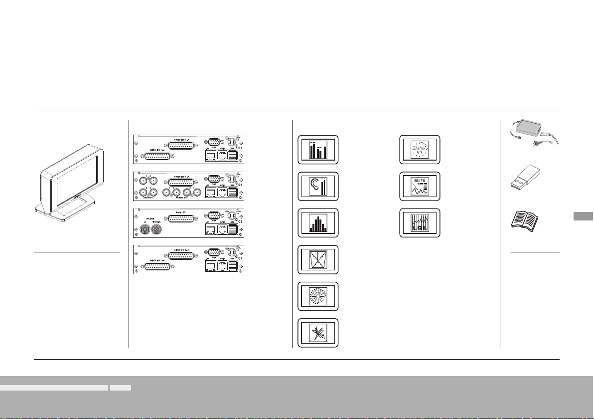
TouchMonitor TM7
Audio Interface as ordered Software Licence, if ordered
Table-top unit 20700
> >
4 x AES3
8 x analog
HW20711
4 x AES3id
8 x analog
HW20712
4 x AES3
3G-SDI
> >
HW20714
8 x AES3
HW20715
Multichannel
mode
SW20001
Loudness and
SPL display
SW20002
RTA - Real Time
Analyzer
SW20003
SSA - Surround
Sound Analyzer
SW20004
Radar Display
SW20005
Premium PPM
+ Vectorscope
SW20006
Timecode
Reader
SW20008
BLITS
SW20013
Logging Data
Server
SW20014
Power supply
USB stick
EN
Short manual
EN-11Manual | TouchMonitor TM7/TM9 Before You Begin | Scope of Delivery
Page 12
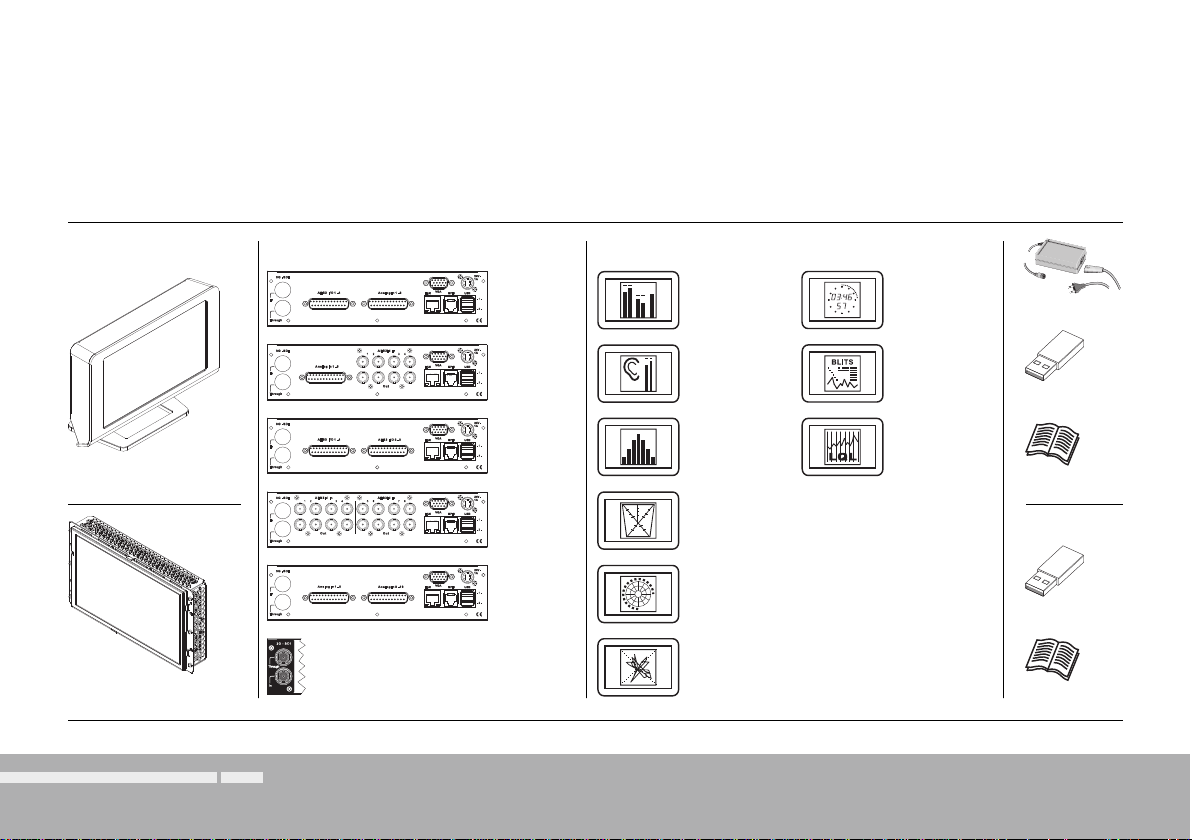
TouchMonitor TM9
Audio Interface as ordered Software Licence, if ordered
Table-top unit 20900
OEM version 20900OEM
Before You Begin | Scope of Delivery EN-12 Manual | TouchMonitor TM7/TM9
> >
4 x AES3
8 x analog
HW20911
4 x AES3id
8 x analog
HW20912
8 x AES3
>
>
HW20913
8 x AES3id
HW20914
16 x analog
HW20915
3G-SDIOption
HW20930
Multichannel
mode
SW20001
Loudness and
SPL display
SW20002
RTA - Real Time
Analyzer
SW20003
SSA - Surround
Sound Analyzer
SW20004
Radar Display
SW20005
Premium PPM
+ Vectorscope
SW20006
Timecode
Reader
SW20008
BLITS
SW20013
Logging Data
Server
SW20014
>
>
Power supply
USB stick
Short manual
USB stick
Short manual
Page 13

Installation
The TouchMonitor TM7 and TM9 table-top units (20700/20900) are
designed for free positioning on tables, desks, et. al. All necessary
power supply voltages are supplied through the +24 V DC 1 A connector. Use with power supply model STD-2427PA, manufactured
by Adapter Technology Co Ltd. (which is the external power supply
unit RTW 1168-R wide voltage power supply, included in 20700 and
20900 packages). The units feature a 7“ resp. 9“ VGA 16 : 9 touch
screen.
Optional an external standard16 : 9 VGA monitor can be connected
for external reading of the display.
Optional an external computer mouse or a Wacom® graphics tablet
can be connected to one of the USB interfaces.
The other ports and interfaces are connected with the appropriate
standard connection cables.
ATTENTION – Please read before installing:
• Before installing the unit please study the safety instructions and
the information on connection and pin assignment.
• An external overcurrent protective device (2 A max.) shall be
installed when using an external 24 V DC power supply!
• Make sure that the delivered power supply unit is not connected.
• Connect your signal sources and all your other components to the
appropriate connectors, using the correct standard connection
cables for the components. Take care about the pin assignment!
• Optionally, connect an external standard 16 : 9 VGA monitor to
the VGA output, using a standard VGA connection cable. The VGA
cable shall be of 10 to 15 m maximum length.
• Finally, connect the locking 4-pin low voltage connector of the
external power supply to the +24 V DC 1 A connector on the rear.
Connect the external power supply to mains.
• The TouchMonitor will initiate its system startup sequence. After
the boot-up the unit is ready for use.
EN-13Manual | TouchMonitor TM7/TM9 Installation
EN
Page 14

Connection
4-pin locking
low voltage
connector
TouchMonitor TM9TouchMonitor TM7
Optional:
3G-SDI interface
option
HW20930
4-pin locking
low voltage
connector
External:
VGA monitor 16 : 9
HW20711
(pictured):
HW20712:
HW20714:
HW20715:
AES3 In/Out 1 - 4
(Sub-D)
AES3id In/Out 1 - 4
(8 x BNC)
3G-SDI In/Through
(2 x BNC)
AES3 In/Out 1 - 4
(Sub-D)
or
Installation | ConnectionEN-14 Manual | TouchMonitor TM7/TM9
Analog In 1 - 8
(Sub-D)
Analog In 1 - 8
(Sub-D)
Audio I/O
(Sub-D)
AES3 In/Out 5 - 8
(Sub-D)
LAN
(RJ-45)
External:
USB mouse
Wacom® graphics tablet
VGA
GP IO
(RJ-11)
24 V DC, 1 A
USB A 2.0
(Full Speed)
HW20911
(pictured):
HW20912:
HW20913:
HW20914:
HW20915:
AES3 In/Out 1 - 4
(Sub-D)
Analog In 1 - 8
(Sub-D)
AES3 In/Out 1 - 4
(Sub-D)
AES3id In/Out 1 - 4
(8 x BNC)
Analog In 1 - 8
(Sub-D)
or
External:
VGA monitor 16 : 9
Analog In 1 - 8
(Sub-D)
AES3id In/Out 1 - 4
(8 x BNC)
AES3 In/Out 5 - 8
(Sub-D)
AES3id In/Out 5 - 8
(8 x BNC)
Analog In 9 - 16
(Sub-D)
or
VGA
LAN
GP IO
(RJ-45)
(RJ-11)
External:
USB mouse
Wacom® graphics tablet
24 V DC, 1 A3G-SDI: Through In
USB A 2.0
(Full Speed)
Page 15

Pin Assignment
Analog In 1 -8, Analog In 9 - 16 (electr
Pin: Function:
1 Analog input 8 resp. 16 (+, hot)
14 Analog input 8 resp. 16 (–, cold)
2 Shield/chassis
15 Analog input 7 resp. 15 (+, hot)
3 Analog input 7 resp. 15 (–, cold)
16 Shield/chassis
4 Analog input 6 resp. 14 (+, hot)
17 Analog input 6 resp. 14 (–, cold)
5 Shield/chassis
18 Analog input 5 resp. 13 (+, hot)
6 Analog input 5 resp. 13 (–, cold)
19 Shield/chassis
7 Analog input 4 resp. 12 (+, hot)
20 Analog input 4 resp. 12 (–, cold)
8 Shield/chassis
21 Analog input 3 resp. 11 (+, hot)
9 Analog input 3 resp. 11 (–, cold)
22 Shield/chassis
10 Analog input 2 resp. 10 (+, hot)
23 Analog input 2 resp. 10 (–, cold)
11 Shield/chassis
24 Analog input 1 resp. 9 (+, hot)
12 Analog input 1 resp. 9 (–, cold)
25 Shield/chassis
13 not used
. balanced, 25-pin Sub-D-F)
P i n 1
P i n 2
P i n 3
P i n 4
P i n 5
P i n
6
P i n 7
P i n 8
P i n 9
P i n 1 0
P i n 1 1
P i n 1 2
P i n 1 3
(External view of the connector)
P i n 1 4
P i n 1 5
P i n 1 6
P i n 1 7
P i n 1 8
P i n 1 9
P i n 2 0
P i n 2 1
P i n 2 2
P i n 2 3
P i n 2 4
P i n 2 5
AES3 I/O 1 - 4, AES3 I/O 5 - 8, Audio I/O (transf.-bal., 25-pin Sub-D-F)
Pin: Function:
1 Digital output 4 resp. 8 (+, hot)
14 Digital output 4 resp. 8 (–, cold)
2 Shield/chassis
15 Digital output 3 resp. 7 (+, hot)
3 Digital output 3 resp. 7 (–, cold)
16 Shield/chassis
4 Digital output 2 resp. 6 (+, hot)
17 Digital output 2 resp. 6 (–, cold)
5 Shield/chassis
18 Digital output 1 resp. 5 (+, hot)
6 Digital output 1 resp. 5 (–, cold)
19 Shield/chassis
7 Digital input 4 resp. 8 (+, hot)
P i n 1
P i n 2
P i n 3
P i n 4
P i n 5
P i n
6
P i n 7
P i n 8
P i n 9
P i n 1 0
P i n 1 1
P i n 1 2
P i n 1 3
(External view of the connector)
P i n 1 4
P i n 1 5
P i n 1 6
P i n 1 7
P i n 1 8
P i n 1 9
P i n 2 0
P i n 2 1
P i n 2 2
P i n 2 3
P i n 2 4
P i n 2 5
20 Digital input 4 resp. 8 (–, cold)
8 Shield/chassis
21 Digital input 3 resp. 7 (+, hot)
9 Digital input 3 resp. 7 (–, cold)
22 Shield/chassis
10 Digital input 2 resp. 6 (+, hot)
23 Digital input 2 resp. 6 (–, cold)
11 Shield/chassis
24 Digital input 1 resp. 5 (+, hot)
12 Digital input 1 resp. 5 (–, cold)
25 Shield/chassis
13 not used
NOTE - The AES3 inputs are permanently terminated with 110 .
EN
EN-15Manual | TouchMonitor TM7/TM9 Installation | Pin Assignment
Page 16

Pin Assignment (continued)
AES3id In/Out 1 - 4, AES3id In/Out 5 - 8, 3G-SDI (unbal., BNC-F)
Pin: Function:
Pin: Signal
Ring: Shield/chassis
(External view of the
AES3id connector)
(External view of the
3G-SDI connector)
NOTE - The AES3id inputs and the 3G-SDI inputs are permanently
terminated with 75 .
24 V - 1 A (4-pin locking low voltage connector, Typ Binder 710)
Pin: Function:
1 - 2 +24 V DC
3 - 4 0 V
Pin 3
Pin 4
(External view of the mounted connector)
Pin 2
Pin 1
NOTE - An external overcurrent protective device (2 A max.) shall be
installed when using an external 24 V DC power supply!
GP IO (RJ-11 6P6C socket)
External control of functions defi ned in the Global Keyboard menu. The inputs
defi ned as „active low“ have to be switched against 0 V (Pin 1).
Pin: Function:
1 GND (0 V)
2 - 6 Function acc. to defi nition in the menu
(External view of the connector)
USB-A
2 Full Speed USB 2.0 interfaces for the connection of USB sticks (Licence
handling, presets, updates) and an external mouse or Wacom® tablet.
VGA (15-pin Sub-D-F)
Pin: Function:
1 R | Video signal
2 G |
3 B |
4 - 8 GND
9 +5 V
P i n 1
P i n 2
P i n 3
P i n 4
P i n 5
(External view of the connector)
P i n 6
P i n 7
P i n 8
P i n 9
P i n 1 0
P i n 1 1
P i n 1 2
P i n 1 3
P i n 1 4
P i n 1 5
10 - 11 GND
12 SDA
13 H-sync
14 V-sync
15 SCI
NOTE - The VGA cable shell not exceed 15 m lenght!
LAN
RJ-45 standard network connector (10/100 MBit)
Installation | Pin AssignmentEN-16 Manual | TouchMonitor TM7/TM9
Page 17

Getting Started
System Start-up
Before connecting the TouchMonitor to the power supply, please
make sure, that the following connections are made according to
your unit (TM7, TMR7, TM9) and to your individual needs:
• Analog and/or digital audio input signals (depending on the hardware confi guration of your unit)
• Digital outputs (if available)
• Optional external standard 16 : 9 VGA monitor
• Optional USB mouse
• LAN/Ethernet (if needed)
• Power supply
When the TouchMonitor is connected to the power supply, it will initiate its system startup sequence. After the boot-up the unit is ready
for use.
We assume that you are starting your TouchMonitor for the fi rst time.
You now should make some global settings to adopt the unit to your
audio system. After this short procedure you can create your fi rst preset to work with.
NOTE - The fi gures in the following paragraphs may show some options that are not available on your unit. The scope of available
options depends on model (TM7, TMR7, TM9), hardware confi guration, and activated licences.
EN-17Manual | TouchMonitor 7“/9“ Series common Getting Started | System Start-up
EN
Page 18

Adapt the TouchMonitor to your Audio System
The description below leads you through the main steps of the global settings to confi gure the TouchMonitor once for the use with your audio
system. These settings are not altered by loading new presets.
1. If not visible, touch the empty space of the screen to display the
control bar.
1.
2.
2. Touch the Menu key in the right section of the control bar to
access the menu system showing the Main Menu.
3.
3. Touch the System key
. This will access the System Menu. The
General sub menu will be active (marked in the control bar).
. If needed, touch Language and select your language in the right
4
half of the menu. The selection will be shown on the Language key.
The new language will be available after reboot.
4.
4.
5.
5. Touch the Audio button in the left section of the control bar to
open the Audio sub menu.
Getting Started | Adapt the TouchMonitor to your Audio System EN-18 Manual | TouchMonitor 7“/9“ Series common
Page 19

6. If your TM unit should use a defi ned reference source, touch the
Sync Reference key and select from the items in the right half
of the menu.
Number and type of available sync reference sources depends
on model and scope of the installed audio interfaces.
7. Touch the Clock key, if you want to set the current date and time.
Start the internal clock with touching the Set time key.
6.
EN
7.
8.
8. Touch the Save key to store your global settings. The unit turns
back to normal display mode.
EN-19Manual | TouchMonitor 7“/9“ Series common Getting Started | Adapt the TouchMonitor to your Audio System
Page 20

Create Your Own Preset
Presets are used to defi ne and edit all the specifi c settings for your work fl ow. So you can create audio groups containing a defi ned signal
source selection and one or more instruments sharing this domain and showing parameters of audio signals. Also you can create non-audio
groups containing intruments, that are not related to audio input signals, like clock, hardware status monitor, or global keyboard.
If you want to create a preset from scratch, please proceed as follows:
1. If not visible, touch the empty space of the screen to display the
control bar.
4. Touch the New button to create a new preset. A preset with an
editable default name is created (see next fi gure, touch Preset
Name to edit).
2. Touch the Menu key in the right section of the control bar to
access the menu system starting with the Main Menu.
3. Touch the Preset Management key. The Internal Presets menu
appears.
3.
4.
Getting Started | Create Your Own PresetEN-20 Manual | TouchMonitor 7“/9“ Series common
Page 21

5. Touch the New Audio key to create the fi rst audio group.
5.
6. The Domain key is marked, select the domain of the required
signal source in the right half of the menu.
7. The Mode key appears and is marked, select your channel mode
in the right half of the menu.
The number of modes depends on your model and the activated software licences.
7.
8. If the Loudness and SPL display software licence (SW20002)
is activated, the Select Loudness sub menu appears. Select the
loudness type you prefer.
EN
6.
8.
EN-21Manual | TouchMonitor 7“/9“ Series common Getting Started | Create Your Own Preset
Page 22
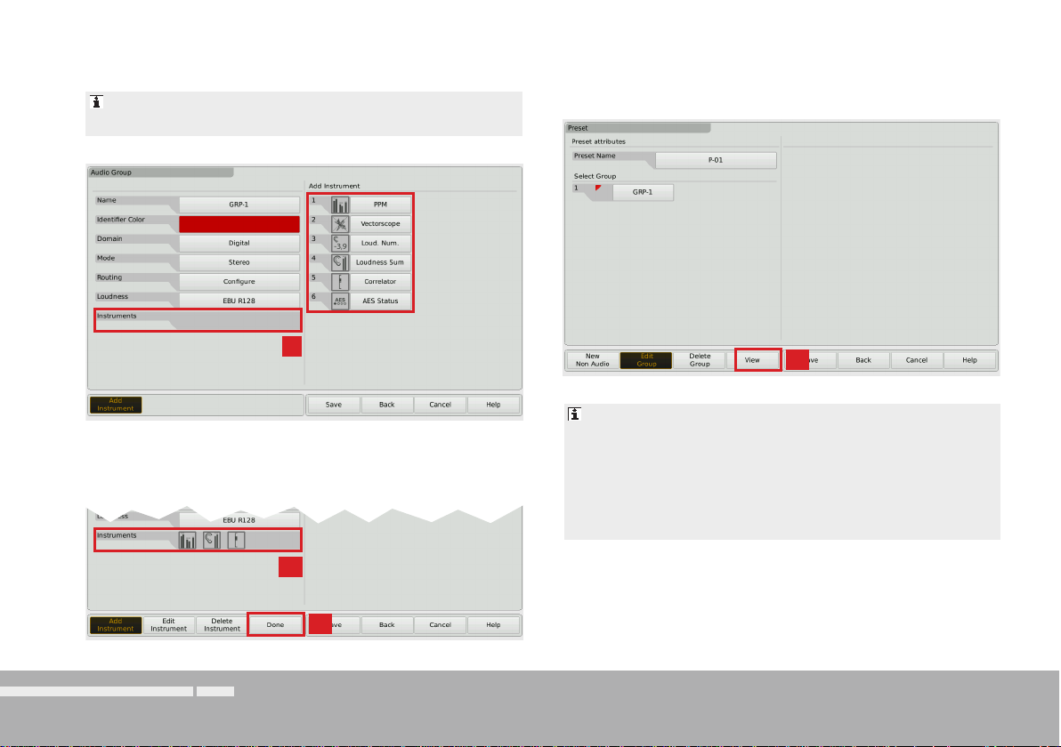
9. The Instruments fi eld appears on the left, and a list of the availa-
ble instruments is shown on the right.
The number of instruments depends on the activated software licences.
11. If you have done all your selections, touch the Done key. This returns you to the Preset menu.
9.
12.
The Preset menu now shows the audio group you just created, marked with a small colored triangle in the upper left
10. Touch the keys of the instruments you want to use. The icon of
every selection is placed on the Instruments fi eld on the left.
edge. In normal operation, all instruments of this group will
always be identifi ed by this color
. The identifi er colors
make it easy to distinguish the group an instrument belongs
to, if you have created several groups.
10.
12. Touch the View key to start arranging the instruments on the
screen. The defi ned groups containing the instruments are shown
11.
Getting Started | Create Your Own PresetEN-22 Manual | TouchMonitor 7“/9“ Series common
on the left (see next fi gure).
Page 23

12.
The View Screen is a comprehensive editor used to position
and size the instruments defi ned in the current preset. All
instruments needed must be positioned before you can watch
them in normal display mode.
13. Touch an instrument icon. It will be applied to the upper left edge
of the graphical screen representation.
14. Use the Position and Size keys to resize the instrument and
place it to another position.
14.
15. Do so with the other instrument icons.
In case of two or more instruments overlapping, a warning will
be displayed. Move the overlapping instrument icon to an unused area. Use the P
osition and Size keys.
15.
EN
13.
EN-23Manual | TouchMonitor 7“/9“ Series common Getting Started | Create Your Own Preset
Page 24
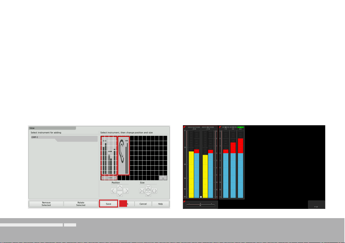
16. When the screen layout satisfi es your demands (you also can rotate instruments), touch the Save key below in the control bar.
17. This will return you to normal display mode showing the new
screen layout resp. the new preset you created.
16.
Getting Started | Create Your Own PresetEN-24 Manual | TouchMonitor 7“/9“ Series common
Page 25
Working with Instruments and Presets
In normal display mode the TouchMonitor shows the instruments and the screen layout defi ned in the currently loaded preset. You can use
the control bar keys to operate a selected instrument or to load a new preset.
If the control bar is not visible, just touch the screen. Then it will be displayed for some seconds to make your selection.
If you want to use the functions of an instrument, please proceed as follows:
1. Touch the screen area of the instrument you want to use. It will be
put into focus. The left section of the control bar now shows the
specifi c functions of the focused instrument.
The current selected instrument is marked with a colored
frame around. It represents the identifi er color like the colored
triangle.
2. Select the desired function.
If there are more than 6 functions, use the More key.
If a function key opens another level of functions, then use
the Close key to get back to the previous level.
EN
EN-25Manual | TouchMonitor 7“/9“ Series common Getting Started | Working with Instruments and Presets
Page 26

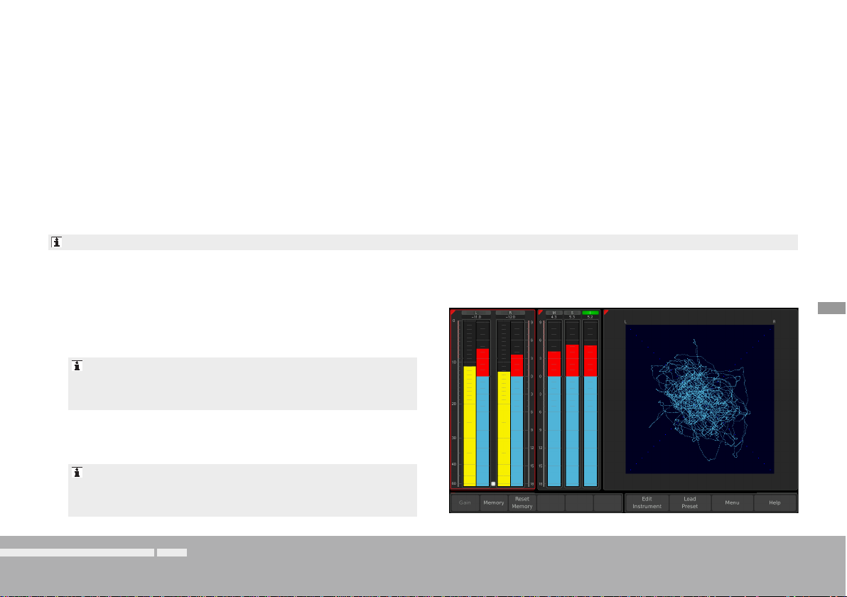
If you want to load another preset, please proceed as follows:
1.
1. Touch the Load Preset key in the right section of the control bar.
A menu page with a list of presets available is shown.
2.
2. Touch the preset you want to use.
The current selected and used preset is marked as active.
In normal display mode, the name of the active preset is displayed in the lower right edge of the screen.
3. The selected preset is loaded. The unit automatically switches
back to normal display mode and displays the selected preset.
Depending on the unit‘s type the functions like Loudness or
Vectorscope shown on the screenshots require further software
licences being activated (for details please see next chapter).
Getting Started | Working with Instruments and PresetsEN-26 Manual | TouchMonitor 7“/9“ Series common
Page 27

Software Modules (Licences Handling)
EN
The TouchMonitor features a modular software concept that enables
you to add new functions and instruments to your unit at any time. The
Licences menu is used to view the licences currently installed on the
TouchMonitor and to acquire new licences. Instruments and functions
already activated are marked with an Installed sign. Instruments and
functions that are not installed have an order key. On the Licences
menu you only will fi nd licencing options that are provided for your
model and were already available at the release date of the software
version installed on the unit.
NOTE - Some licences require others to be installed fi rst before you can aquire them. Please note the corresponding information
while purchasing licences.
NOTE - The fi gures in the following paragraphs may show
licences that are not available on your unit depending on model
(TM7, TMR7, TM9), and hardware confi guration.
EN-27Manual | TouchMonitor 7“/9“ Series common Software Modules (Licences Handling)
Page 28

If you want to acquire new licences, please proceed as follows:
1. Insert a USB memory stick to one of the USB ports on the rear
panel.
4.
2. Touch the empty space of the screen or one of the displayed insstruments, the control bar appears.
2.
3.
3. Touch the Menu key in the right section of the control bar to ac-
cess the menu system showing the Main Menu.
4.
4. Touch the Licences key. The available software licences are dis-
played, the activated ones marked with Installed.
5.
5. T
ouch the order keys of the licences you want to acquire.
6.
Software Modules (Licences Handling) EN-28 Manual | TouchMonitor 7“/9“ Series common
Page 29

6. Touch the Export Requests key displayed in the left section of
the control bar.
The TouchMonitor will establish a folder structure on the USB
stick named /rtw/licence. An encrypted licence request fi le
(nnn_nn.lrf) depending on the individual serial number of the
hardware unit is stored to this folder.
7. Wait until the menu page confi rming the successful export of the
licence request fi le is displayed.
9. Remove the USB stick from the TouchMonitor, insert it to a USB
port of your computer and send the licence request fi le to your
sales representative.
Alternatively to the information of step 6, in single cases this
fi le may also be found in folder /rtw/tm7h/licence resp.
/rtw/tm9h/licence.
8.
EN
8.
8. Touch the Done key. This turns you back to the Main Menu.
With the USB stick inserted, there are additional keys on the
right to export or import individual presets or the global settings to the resp. from the USB stick.
10. After purchasing the licence, a new fi le (nnn_nn.lf) containing the
licence request fi le will be sent to you.
The returned licence fi le is only valid for the individual unit the
licence request fi le was created on.
11. The licence fi le (nnn_nn.lf) shall be stored to the same folder as
the licence request fi le on the USB stick.
EN-29Manual | TouchMonitor 7“/9“ Series common Software Modules (Licences Handling)
Page 30
12. Unmount the USB stick from the computer system! Not till then
remove it from your computer!
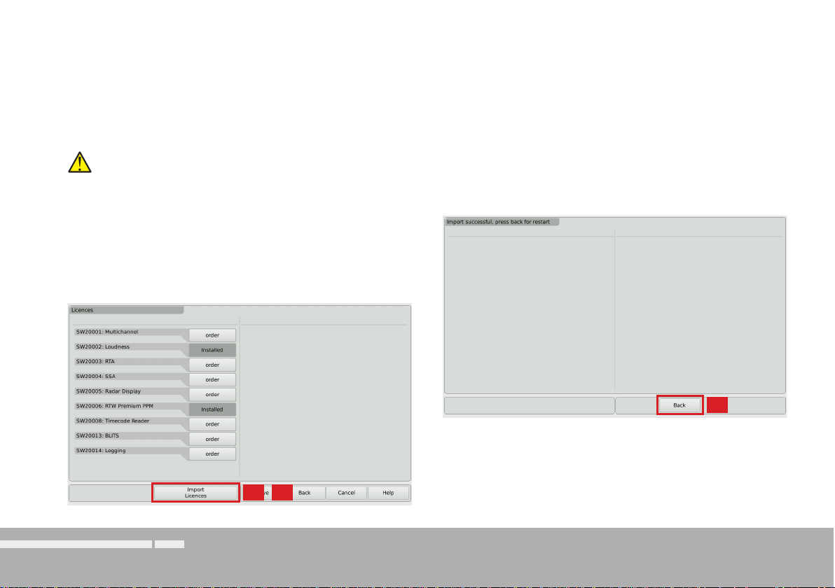
15. The licence fi le will be recognized, and an Import Licences key
will be shown in the left section of the control bar
.
ATTENTION! - Unmounting from the computer system
shall be performed to avoid damage of the copied update fi le!
16. Touch the Import Licences key to import the licence fi le to the
unit.
13. Remove the unmounted USB stick from your computer and insert
it to one of the USB ports on the rear panel of the TouchMonitor.
14. Access the Licences menu as described in steps 2. to 4.
17. When the import is fi nished, reb
oot the TouchMonitor by touching
the Back key.
15.
16.
Software Modules (Licences Handling) EN-30 Manual | TouchMonitor 7“/9“ Series common
18. The licenced instrument or function is now permanently available.
17.
Page 31

Software Update
EN
If you want to add new functions and instruments to your unit at any
time, periodic maintenance of the system software is neccessary,
because you only will fi nd options and licences that were provided for
your model and were already available at the release date of the software version installed on the unit.
Software updates are available from your sales partner or at members
area of our web site (login page: http://www.rtw.de/en/sales-support/manuals-software.html). After log-in click „Audio Monitors“, then
choose the option corresponding to your model.
EN-31Manual | TouchMonitor 7“/9“ Series common Software Update
Page 32

If you want to update your software, please proceed as follows:
1. Copy the update fi le (rtw-tm-fw-n-n.bin, n-n: fi rmware version)
into the main directory of a USB stick.
2. Unmount the USB stick from the computer system! Not till then
remove it from your computer!
ATTENTION! - Unmounting from the computer system
shall be performed to avoid damage of the copied update fi le!
3. Remove the unmounted USB stick from your computer and insert
it to one of the USB ports on the rear panel of the TouchMonitor.
5.
4. If not visible, touch the empty space of the screen to display the
control bar.
5. Touch the Menu key in the right section of the control bar, then
the System key in the Main Menu.
6. Touch the Special key. The additional Start Firmware Update:
rtw-tm-fw-n-n key is displayed.
7. Touch the key. The update starts and takes about 10 minutes.
5.
Software Update EN-32 Manual | TouchMonitor 7“/9“ Series common
8. When the update is fi nished, the TouchMonitor reboots automatically.
Page 33

Specifi cations (Extract)
System
General
Power requirements: +24 V DC (2 A overcurrent protective device shall be installed!)
Current drain: 1 A nominal current, 2.5 A power-up current (10 μsec.)
Power dissipation: TM7: appr. 8.5 W/11 W; TM9: appr. 12.5 W/15 W (w/o/with SDI)
Display: 7“ (TM7) or 9“ (TM9) TFT touch screen 16 : 9
Connectors: 1 x 15-pin Sub-D-F; VGA output with 800 x 480 pixel (TM7)/
1024 x 600 pixel (TM9), 65,536 colors, 60 Hz, for connection of
an external 16 : 9 VGA monitor, internal selectable 4 : 3 mode
1 x 4-pin locking low voltage typ 710 (DC)
2 x USB A; USB 2.0 Full Speed connectors for:
• USB sticks for licence handling, preset export and import,
software updates
• external computer mouse or Wacom® graphics tablet
1 x GPIO (RJ-11-6P6C, for remote control of defi ned functions)
1 x LAN (RJ-45)
with HW20711: 2 x 25-pin Sub-D-F (analog and digital)
with HW20712: 1 x 25-pin Sub-D-F (analog), 8 x BNC-F (digital)
with HW20714: 1 x 25-pin Sub-D-F (digital), 2 x BNC-F (3G-SDI)
with HW20715: 2 x 25-pin Sub-D-F (digital)
with HW20911: 2 x 25-pin Sub-D-F (analog and digital)
with HW20912: 1 x 25-pin Sub-D-F (analog), 8 x BNC-F (digital)
with HW20913: 2 x 25-pin Sub-D-F (digital)
with HW20914: 16 x BNC-F (digital)
with HW20915: 2 x 25-pin Sub-D-F (analog)
Dimensions TM7: • 20700: 198 x 163 x 46 mm (W x H x D)
• 20700OEM: 188 x 109 x 45 mm (W x H x D)
Dimensions TM9: • 20900: 245 x 185.5 x 46.5 mm (W x H x D)
• 20900OEM: 235 x 135 x 45 mm (W x H x D)
Weight: approx. 2,7 kg (TM9 table-top unit without power supply)
Operating temperature: in the range from +5° to +40° C
Functions (with all licences activated)
• Operating using a fi nger (touch screen), mouse, or tablet
• Instruments can be freely scaled and randomly positioned
• PPM: Surround (3.1, 5.0, 5.1, 7.1), 2-channel, multichannel
• Loudness-Meter: EBU R128, ITU-R BS.1770-3/1771-1,
ATSC A/85, ARIB, and customer specifi c, SPL meter
• Loudness Range instrument (LRA)
• Logging Data Server
• Radar Loudness Meter (TC electronic®)
• Moving Coil instrument (BR, VU, Loudness scales)
• Surround Sound Analyzer
• 10-fold Multi-Correlator with LFE mode, Stereo correlator
• 31 and 61 band spectrum analyzer
• 2-channel audio vectorscope
• BLITS, Gain reduction instrument
• AES3 statusmonitor, Numerical displays, Timecode
Analog Inputs
HW20711: 8 analog inputs, 25-pin Sub-D-F connector
HW20712: 8 analog inputs, 25-pin Sub-D-F connector
HW20911: 8 analog inputs, 25-pin Sub-D-F connector
HW20912: 8 analog inputs, 25-pin Sub-D-F connector
HW20915: 16 analog inputs, 2 x 25-pin Sub-D-F connectors
Reference level: adjustable in the range from 0 dBu to +10 dBu
Max. input level: +24 dBu
Impedance: > 10 k, electronically balanced
Frequency range: 20 Hz to 22 kHz at 48 kHz
EN
EN-33Manual | TouchMonitor TM7/TM9 Specifi cations (Extract)
Page 34

Digital Inputs
HW20711: 4 AES3 inputs (transformer balanced, 110 ), 25-pin
Sub-D-F connector with 4 inputs and 4 outputs
HW20712: 4 AES3id inputs (unbalanced, 75 ), 8 BNC-F connectors
with 4 inputs and 4 outputs
HW20714: 4 AES3 inputs (transformer balanced, 110 ), 25-pin
Sub-D-F connector with 4 inputs and 4 outputs and 3G-SDI
interface with BNC-F connectors In and Through
HW20715: 8 AES3 inputs (transformer balanced, 110 ), 2 x 25-pin
Sub-D-F connector with 4 inputs and 4 outputs each
HW20911: 4 AES3 inputs (transformer balanced, 110 ), 25-pin
Sub-D-F connector with 4 inputs and 4 outputs
HW20912: 4 AES3id inputs (unbalanced, 75 ), 8 BNC-F connectors
with 4 inputs and 4 outputs
HW20913: 8 AES3 inputs (transformer balanced, 110 ), 2 x 25-pin
Sub-D-F connector with 4 inputs and 4 outputs each
HW20914: 8 AES3id inputs (unbalanced, 75 ), 16 BNC-F connectors
with 8 inputs and 8 outputs
HW20930: 3G-SDI interface with BNC-F connectors In and Through
Sampling rates: 44.1, 48, 96 kHz, synchronisation via digital input signal
Digital Outputs
HW20711: 4 AES3 outputs, 25-pin Sub-D-F connector (4 in, 4 out)
HW20712: 4 AES3id outputs, 8 BNC-F connectors (4 in, 4 out)
HW20714: 4 AES3 outputs, 25-pin Sub-D-F connector (4 in, 4 out) and
3G-SDI interface with BNC-F connectors In and Through
HW20715: 8 AES3 outputs, 2 x 25-pin Sub-D-F connector (4 in, 4 out each)
HW20911: 4 AES3 outputs, 25-pin Sub-D-F connector (4 in, 4 out)
HW20912: 4 AES3id outputs, 8 BNC-F connectors (4 in, 4 out)
HW20913: 8 AES3 outputs, 2 x 25-pin Sub-D-F connector (4 in, 4 out each)
HW20914: 8 AES3id outputs, 16 BNC-F connectors (8 in, 8 out)
Sampling rates: referenced to digital inputs or internal clock
Basic Stereo PPM (Standard Software)
General
Input sources: analog, digital, 3G-SDI, depending on mounted audio interface
2-ch. peakmeter: for one installed Stereo channel pair L/R
Displays: • Peak level
• Peak hold
• Numerical value of the display
Functions: • Gain (+20 dB, +40 dB depending on selected standard)
• Peak hold on/off, Memory, Reset
Analog Peakmeter
Analog scales: • DIN5: +5 .. -50 dB,
• Nordic: +12 .. -42 dB,
• BR IIa: 7 .. 1 (British),
• BR IIb: +12 .. -12 dB (British),
Integration time: according to standard or 20 ms, 10 ms, 1 ms, 0.1 ms
Peak hold display: 1 s, 2 s, 4 s, 10 s, 20 s, 30 s, manual reset or off
Digital Peakmeter
Word width: 24 bit
Digital scales: • TP60: +3 .. –60 dB
• Dig60: 0 .. –60 dB
• DIN5: +5 .. -50 dB,
• Nordic: +12 .. -42 dB,
• BR IIa: 7 .. 1 (British),
• BR IIb: +12 .. -12 dB (British),
Headroom/Headr. Ref: adjustable in 1 dB steps in the range from 0 to –20 dB
Operation range: adjustable in 1 dB steps in the range from 0 to –20 dB
Attack time: as standard or selectable: Sample, 20 ms, 10 ms, 1 ms, 0.1 ms
British scales also 150 ms selectable
Gain: +20 dB, +40 dB depending on selected standard
High-pass fi lter: Off, 5 Hz, 10 Hz, 20 Hz
Peak hold display: 1 s, 2 s, 4 s, 10 s, 20 s, 30 s, manual reset or off
Over display hold time: 1 s or manual
PPM Over threshold: Full Scale, Full Scale -1LSB, Full Scale -2LSB, –0.1 dBFS,
–0.5 dBFS, –1 dBFS, –2 dBFS, –3 dBFS
PPM Over attack time: 1 to 15 samples
PPM Over word width: 16 to 24 Bit, selectable
True Peak Over
threshold: –1.0 dBTP, –2.0 dBTP, –3.0 dBTP, –4.0 dBTP
Specifi cations (Extract)EN-34 Manual | TouchMonitor TM7/TM9
Page 35

EC Declaration of Conformity
EC Declaration of Conformity | Directive 2004/108/EG and Directive 2006/95/EG
We, RTW GmbH & Co.KG, Elbeallee 19, 50765 Köln, Germany,
declare under sole responsibility that the products of the
RTW TouchMonitor 20900 Series and 20700 Series
(OEM units / table-top and plug-in units with mains adapter)
meet the intend of the Directive 2004/108/EG and the Directive
2006/95/EG . Compliance was demonstrated to the following specifi cations as listed in the offi cial Journal of the European Communities:
EMC 2004/108/EG
EN 61000-6-3: 2007-10-01 Emissions:
EN 55022: 2007-06-01 Class B, radiated
EN 55022: 2007-06-01 Class B, conducted
EN 61000-6-1: 2007-12-01 Immunity:
EN 61000-4-2 + A1 + A2: 2002-02-01
EN 61000-4-4: 2005-09-01
EN 61000-4-5: 2007-08-01
Safety 2006/95/EG
EN 60950-1: 2007-01-01
Tested and documented by the following companies:
EN
SERCO GmbH, Bonn, accredited EMC laboratory
RTW GmbH & Co.KG, Cologne
Date and signature of the responsible person:
2010-12-01
on behalf of RTW
EN-35Manual | TouchMonitor TM7/TM9 EC Declaration of Conformity
Page 36

RoHS Declarations of Conformity
RoHS Declaration of Conformity for TM7 | Directive 2011/65/EU
We, RTW GmbH & Co.KG, Am Wassermann 25, 50829 Köln,
Germany, declare under sole responsibility that the products of the
RTW TouchMonitor TM7 Series
consisting of the components:
• 20700 (TM7 main unit in a table-top frame)
• 20700OEM (TM7 main unit, OEM)
• 20700-3U (TM7 main unit in a 19“/3U/42HP rack-mount
frame)
• 20700VID (TM7 main unit in a half-19“/3U module for
video racks)
• HW20711 (Audio interface: analog/digital AES3)
• HW20712 (Audio interface: analog/digital AES3id)
• HW20714 (Audio interface: digital AES3/3G-SDI)
• HW20715 (Audio interface: digital AES3)
• TM7-MA3U (Mounting adapter: OEM in 19“/3U/42HP)
• TM7-MAVID (Mounting adapter: OEM in 19“ video racks)
RoHS Declarations of ConformityEN-36 Manual | TouchMonitor TM7/TM9
• TM7-MADT (Mounting adapter: OEM in table-top frame)
• 1167 (Snake cable, 25p. Sub-D/4 x XLR-F/M each)
• 1168-R (Power supply 100 - 240 V AC/24 V DC, 2.7 A)
• 1186 (Snake cable, 4 m, 25p. Sub-D/8 x XLR-F)
meet the intend of the Directive 2011/65/EU on the restriction of the
use of certain hazardous substances in electrical and electronic equipment of the European Parliament and Council from June 8th, 2011.
Tested and documented by the following companies:
RTW GmbH & Co.KG, Cologne
Date and signature of the responsible person:
2013-07-11
on behalf of RTW
Page 37

RoHS Declaration of Conformity for TM9 | Directive 2011/65/EU
We, RTW GmbH & Co.KG, Am Wassermann 25, 50829 Köln,
Germany, declare under sole responsibility that the products of the
RTW TouchMonitor TM9 Series
consisting of the components:
• 20900 (TM9 main unit in a table-top frame)
• 20900OEM (TM9 main unit, OEM)
• HW20911 (Audio interface: analog/digital AES3)
• HW20912 (Audio interface: analog/digital AES3id)
• HW20913 (Audio interface: digital AES3)
• HW20914 (Audio interface: digital AES3id)
• HW20915 (Audio interface: analog)
• HW20930 (Audio interface: 3G-SDI)
• HW20930UPG (Retrofi ttable Audio interface: 3G-SDI)
• TM9-MADT (Mounting adapter: OEM in table-top frame)
• 1167 (Snake cable, 25p. Sub-D/4 x XLR-F/M each)
• 1168-R (Power supply 100 - 240 V AC/24 V DC, 2.7 A)
• 1186 (Snake cable, 4 m, 25p. Sub-D/8 x XLR-F)
meet the intend of the Directive 2011/65/EU on the restriction of
the use of certain hazardous substances in electrical and electronic
equipment of the European Parliament and Council from June 8th,
2011.
Tested and documented by the following companies:
RTW GmbH & Co.KG, Cologne
Date and signature of the responsible person:
2013-07-11
on behalf of RTW
EN-37Manual | TouchMonitor TM7/TM9 RoHS Declarations of Conformity
EN
Page 38

Licenses of the Implemented Software
In addition to the hardware the RTW TouchMonitor 7“ and 9“ Series products also
include a software package for which a variety of licenses apply:
A. Software produced by RTW GmbH & Co.KG, which may only be used for the
proper operation of the product as described in the documentation (application,
DSP programs, boot loader). This software is the property of RTW GmbH &
Co.KG and is protected by German and international copyrights.
B. Open source software, released under the GPL (General Public License) of the
Free Software Foundation (FSF):
1. Linux Kernel
2. TinyLogin
3. Busy Box
4. MTDTools
5. GDBServer
The GPL is located at http://www.gnu.org/licenses/gpl.html.
Only the original English version is legally binding, however.
Depending on the model the start screen of the TouchMonitor contains an adapted image based on the photography “Cologne_CathedralNight-6.jpg” of Lukasz Kryger,
Edingburgh, Scotland. The images fall under the Creative Commons Attribution 2.0 Generic License (http://commons.wikimedia.org/wiki/File:Cologne_CathedralNight-6.
jpg, http://creativecommons.org/licenses/by/2.0/deed.en).
Licenses of the Implemented SoftwareEN-38 Manual | TouchMonitor 7“/9“ Series common
C. Software, released under the LGPL (Lesser General Public License) of the
Free Software Foundation (FSF):
Qt® library of Nokia Corporation
The LGPL is located at http://www.gnu.org/licences/lgpl-2.1.html.
Qt® is registered trademark (brand) of Nokia Corporation, Finland.
D. Software, released under the license of the OpenSSL Project:
„This product includes software developed by the OpenSSL Project for
use in the OpenSSL Toolkit. (http://www.openssl.org/)“
This license is located at http://www.openssl.org/source/license.html.
Some changes have been made to the software packages as listed under B. On
request you can have the source code of the altered software sent to you within
three years of purchasing the product.
Cologne, January 2013
 Loading...