

Page 1

1
SYSTEM 6000 OPERATION - CONTENTS
Introduction
Table of Contents . . . . . . . . . . . . . . . . . . . . . . .1
Basic Operation
Accessing a Mainframe . . . . . . . . . . . . . . . . . .2
Display Layout Explanation . . . . . . . . . . . . . . . .2
Engine Structure and Resources . . . . . . . . . . .2
General Setup
Basic TC Icon Operation . . . . . . . . . . . . . . . . . .3
Operating Levels Scene, Routing, Engine . . . . .3
Operation
Library Page
Recall . . . . . . . . . . . . . . . . . . . . . . . . . . . . . . .4
The Wizard and Algorithm Filter . . . . . . . . . . . .5
Store . . . . . . . . . . . . . . . . . . . . . . . . . . . . . . . .7
Bank . . . . . . . . . . . . . . . . . . . . . . . . . . . . . . . .8
The Naming Display . . . . . . . . . . . . . . . . . . . . .8
Delete . . . . . . . . . . . . . . . . . . . . . . . . . . . . . . .9
Frame Page
Routing . . . . . . . . . . . . . . . . . . . . . . . . . . . . .10
Meters . . . . . . . . . . . . . . . . . . . . . . . . . . . . . .10
Frame System Main
Clock . . . . . . . . . . . . . . . . . . . . . . . . . . . . . . .11
SMPTE . . . . . . . . . . . . . . . . . . . . . . . . . . . . . .11
MIDI . . . . . . . . . . . . . . . . . . . . . . . . . . . . . . . .12
External MIDI Control . . . . . . . . . . . . . . . . . . .14
Net - Software Versions, Network Identifier . . .16
Error Indication and Solution guide . . . . . . . . .16
Frame System I/O
Setup . . . . . . . . . . . . . . . . . . . . . . . . . . . . . . .17
DSP . . . . . . . . . . . . . . . . . . . . . . . . . . . . . . . .17
I/O - Slot A, B & C . . . . . . . . . . . . . . . . . . . . .18
Description of I/O card related parameters . . .18
I/O - Slot B with AES-8 . . . . . . . . . . . . . . . . . .19
Frame System Licenses
Licenses . . . . . . . . . . . . . . . . . . . . . . . . . . . . .20
Engine - Edit Page
General introduction to operate
parameters in algorithms
User Fader Group . . . . . . . . . . . . . . . . . . . . .21
Bypass . . . . . . . . . . . . . . . . . . . . . . . . . . . . . .21
Icon Setup
Icon User Interface . . . . . . . . . . . . . . . . . . . . .22
Touch Fader Sensitivity . . . . . . . . . . . . . . . . . .22
Color Scheme . . . . . . . . . . . . . . . . . . . . . . . .22
Automation - SMPTE
The Auto Page . . . . . . . . . . . . . . . . . . . . . . . .23
Modify . . . . . . . . . . . . . . . . . . . . . . . . . . . . . .23
Insert . . . . . . . . . . . . . . . . . . . . . . . . . . . . . . .23
File . . . . . . . . . . . . . . . . . . . . . . . . . . . . . . . . .23
TC Icon Software Editor for PC & MAC
Presentation . . . . . . . . . . . . . . . . . . . . . . . . . .25
TC Electronic, Sindalsvej 34, DK-8240 Risskov
tcdk@tcelectronic.com
Operation Rev 3.00
English version
Page 2
2
BASIC OPERATION - SYSTEM 6000
Engine Structure
The core element of Mainframe 6000 is the 4 Engine
structure. This structure enables you to run up to four
powerful algorithms/presets simultaneously. Each Engine is
capable of utilizing up to 8 Inputs and 8 Outputs, depending
on the selected algorithm/preset. Up to 16 physical Input
and 16 physical Output channels can be routed in the most
flexible way.
Engine Resources
The Mainframe 6000 offers a sofar unseen amount of DSPresources. The flexible DSP distribution structure lets you
run up to 4 Engine presets at the same time using any
available algorithms. How about running your signal from a
full-blown VSS-5.1 Reverb through a MD-5.1 Multiband
Dynamics algorithm to a Toolbox-5.1 for e.g format
conversion and total control of levels ? Setups like this is
no problem with the System 6000.
Be aware that when using some of the most powerful
algorithms or running at 96kHz, less than 4 Engine presets
can be loaded simultaneously. Required Engine resources
pr. algorithm is listed for each algorithm in the algorithmchapter.
Introduction
This section of the manual is a general introduction on how
to operate System 6000 via the TC Icon. The basic System
6000 consists of a Mainframe with a DSP card and up to
three I/O cards, plus a TC Icon remote with Remote CPU.
Several mainframes as well as several TC Icons can be
hooked up at the same time via a standard Local Area
Network (LAN).
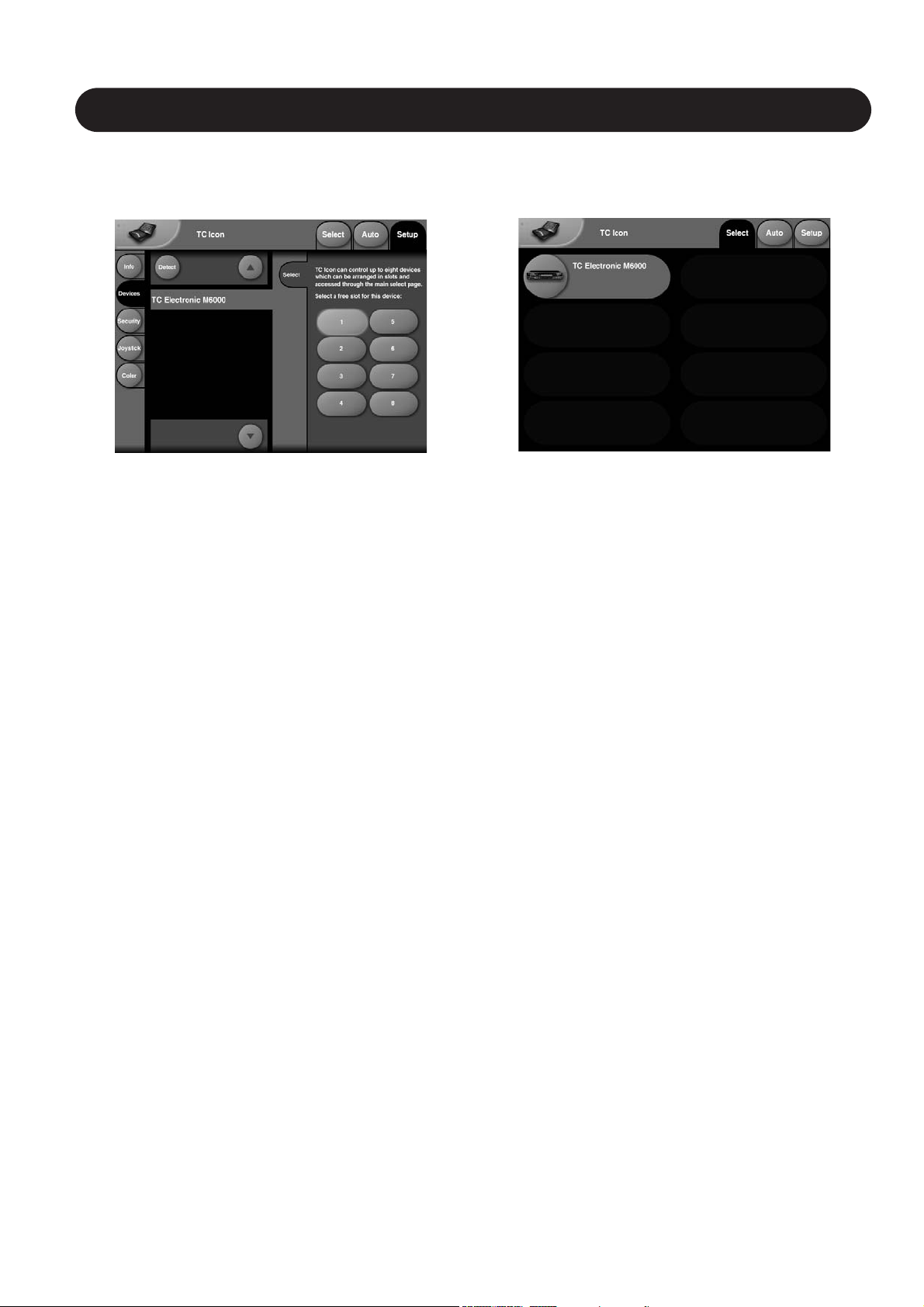
Accessing a Mainframe
First time you connect the Mainframe and TC Icon you
must:
• Power up both devices.
• The TC Icon Setup page appears (see above).
• Press the Detect key.
• When the M6000 mainframe is detected, assign the
frame to one of the eight shortcut keys in the
right side of the display, by pressing any of the keys.
• Go to the Select page (top-tab), and press the
large Mainframe key.
• TC Icon now retrieves data from the Mainframe.
• When ready you will see the Frame - Routing
display, and you are ready to operate the
Mainframe.
To go back to the TC Icon pages press the Icon logo in the
top left corner.
Fig 1
Fig 2
Page 3
3
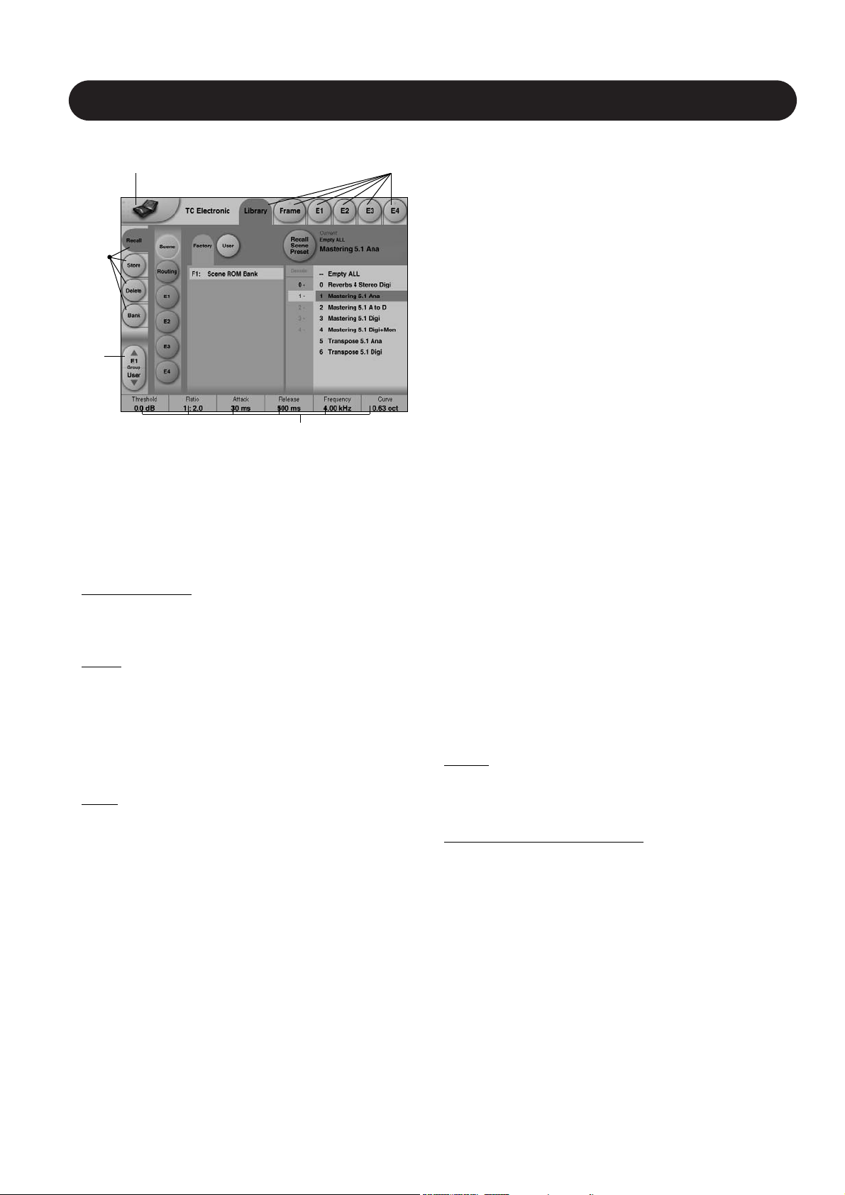
Operating Levels
The Library-Recall page illustrated in Fig.3 leads to
explanation of the “operating levels” in the System 6000.
We differentiate between 3 levels of presets: Scene,
Routing and Engine levels.
• SCENE
This is the most extensive selection you can make. It
includes all four Engine algorithms as well as Physical
and virtual Engine connections. A Scene recall can be
compared to a “total recall.”
• ROUTING
Handles all I/O Routings, including all physical
I/O connections to the Engine I/O’s. No algorithm
(Engine) settings are recalled/stored with this selection.
A Routing preset holds all parameters displayed on the
Frame-Routing page.
• ENGINE
Handles the current algorithm in the selected Engine.
A single preset can be loaded to each of the four
Engines.
Parameter Values and Fader Groups
In the bottom of the display, Fader assignments and values
will always reflect the last modified Engine. Most
parameters can be controlled via the 6 Faders. As some
algorithms hold numerous parameters and we operate with
6 Faders the preset parameters are organized in Fader
Groups. To scroll between the Fader Groups use the
Fader Group selectors.
Parameter value - Fine Adjust
Any parameter value can be adjusted in two accuracies.
A Normal and a Fine Adjust - mode. To switch between the
two modes press the Value Fields above the faders.
As shown in the illustration the Fine Adjust mode will be
indicated with two triangles in the value field.
Fader 6
Any parameter can always be assigned to Fader 6 by
pressing the parameter. Detailed explanation will follow in
the next sections.
User Fader Group - Custom Group
A User Fader group where you can assign parameters to
all 6 faders can also be created and saved along with the
preset. The User Fader group is selected by pressing the
Fader Group selectors.
Did you just unpack the
System 6000 ?
The first time you connect the System 6000 various
settings must be set. Please go to the “Hardware and
Installation” section. This section will also explain how to
upgrade software etc.
BASIC OPERATION - SYSTEM 6000
Fader
Group
Selector
Function
Select
Tabs
Library, Frame &
Engine select Tabs
Parameter values present
in the currently recalled
preset.
Basic TC Icon operation
Navigation in the TC Icon display is easily done when a few
basic elements are explained.
The Icon Link key in the upper left corner allows you to
navigate between the two pages/modes illustrated on the
previous page.
In both modes you:
• Press the top-tabs to do primary selections
• Press the side-tabs or elements to do secondary
selections.
Fig. 1:
Via the “overall” Select & Setup pages you access
overall settings and choices like:
• Selection of which mainframe to operate
• Setting up IP addresses for connected units
• Enable devices to network
• Updates via network or disk
• TC Icon settings such as display appearance
Fig. 2:
The selection of mainframe is done in the Select page
illustrated in “Fig 1”. The page/pages illustrated in Fig. 2
are pages containing parameters on a specific mainframe.
These are the Operating Pages and the page you will be
working in once the system is up and running. Only when
several mainframes are connected you will need to go to
the “overall” Select and Setup pages to switch
mainframe.
The Icon
LINK key
Fig 3
Page 4
Fader
Group
Selector
4
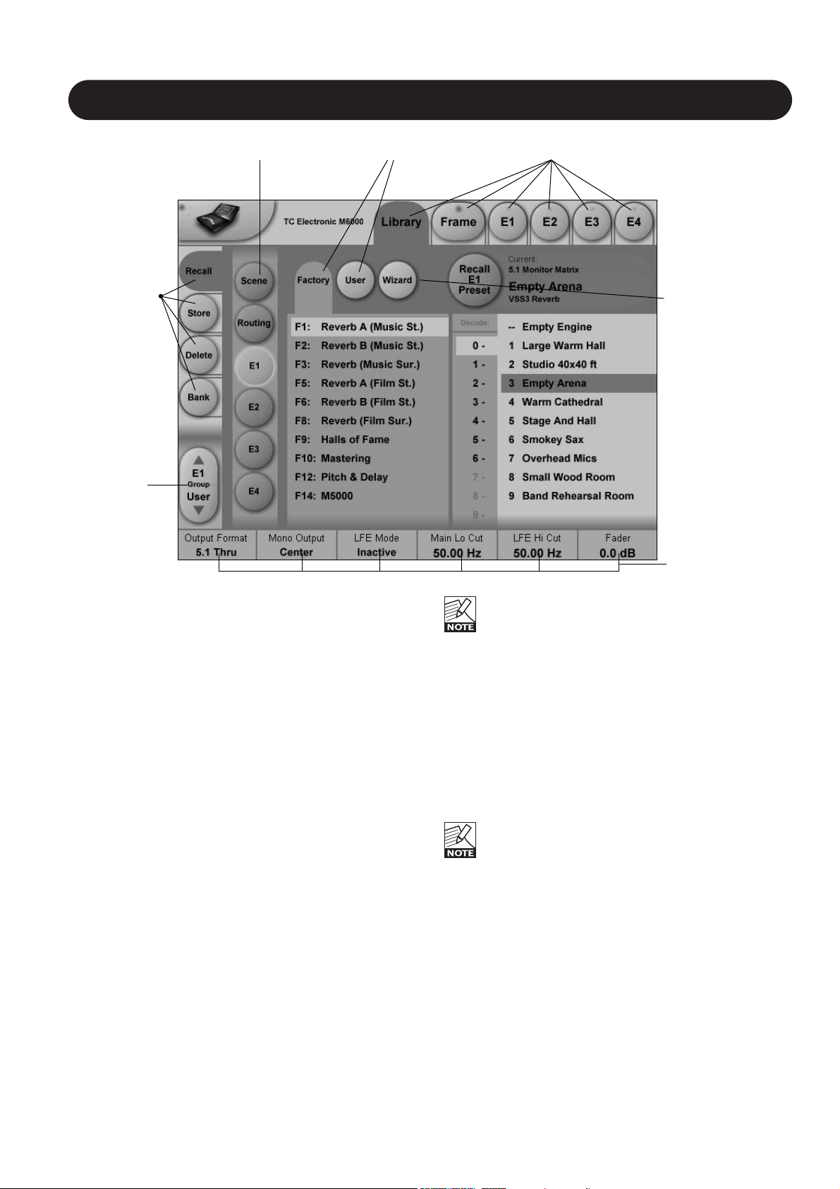
LIBRARY - RECALL
Library Recall
On the Library Recall page the following banks are
available for recall operations.
Scene
Gives access to the following preset banks:
• ROM (Preset #0-49)
• User (Preset #0-49)
Routing
Gives access to the following preset banks:
• ROM (Preset #0-49)
• User (Preset #0-49)
Engine 1-4
Gives access to the following preset banks:
• ROM (Banks #0-13 with 100 presets in each bank.)
• User (Preset #0-99)
Recalling a Scene or an Engine preset
• Press the RECALL tab to select the Recall page.
• Now select the level of: Scene, Routing or Engine 1-4.
• Select which bank you wish to recall from: Factory or
User. If a System 6000 formatted PCMCIA card is
inserted in the Mainframe card-banks will be available
and displayed below the User banks.
• Select presets pressing:
Bank, Decade (=tens) and preset number.
(grayed out numbers indicates that the Decade is empty)
• Press the Recall key to recall/load the preset.
When trying to load an algorithm that requires more
DSP power than currently is free, a Pop-up display
will ask to load the “Empty Engine” preset into an
Engine of your choice. The “Empty Engine” preset is
located as preset 00 in the Reverb Music bank.
Wizard
See next page.
Algorithm Filter
As described on the next page, an Algorithm filter is
available on the Engine recall pages. With this filter you
can narrow down your preset recall options by selecting
specific filter categories.
The Algo Filter key indicates when the filter is
active/inactive.
When the filter is active you can only recall the
presets defined via the algorithm filters.
Operation Level Tabs Bank Selectors
Function
Select
Tabs
Library, Frame and Engine selectors
Parameter Fader
values present in
the last modified
Engine.
Wizard
Page 5
5
THE WIZARD & ALGORITHM FILTER
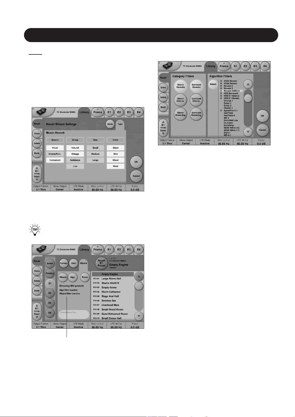
Introduction
To easily find the perfect preset for your application among
the vast amount of presets available in the System 6000,
we have added a Wizard function. Basically the Wizard
allows you to set up a few criterias and thereby narrow
down the pool of presets to select from. All Reverb Factory
presets are marked with Wizard category-tags. When
storing User presets you can assign a Wizard category tag
yourself to each preset. To further narrow down your
selection you can use the Algorithm Filter. Via this filter you
can select categories or specific algorithms to select from.
Finally you can search on preset names that includes
specific words such as “Hall or Cathedral”.
The Wizard is of course 100% non-destructive and
you can at any time press Reset to cancel all Wizard
settings and obtain full access to all presets.
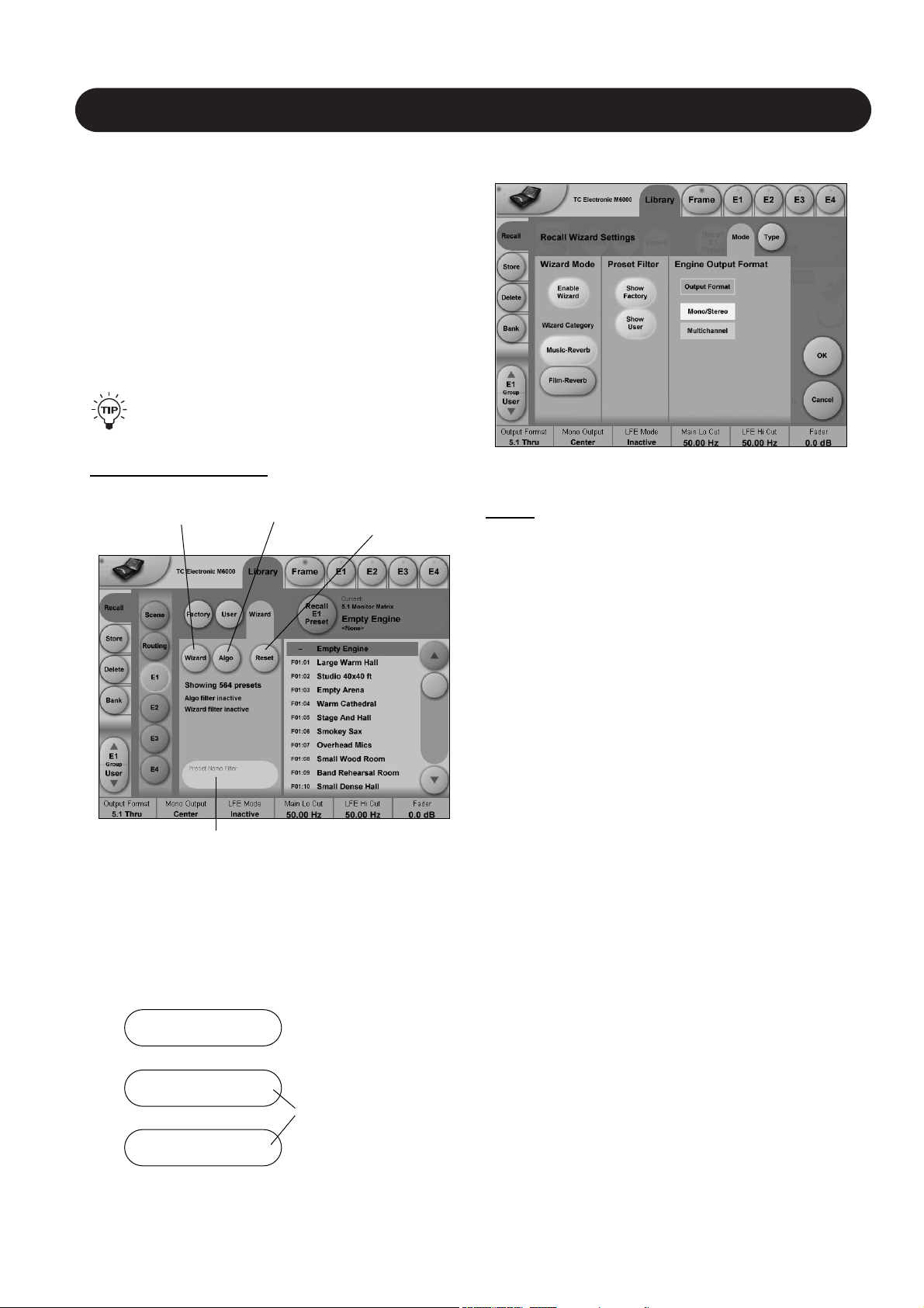
The Wizard
To access; press the Wizard tab on the Wizard “main-page”.
Mode
Enable Wizard
Press to enable the Wizard.
Wizard Category
Select which main categories you would like to select
presets from. Options are: Music-Reverb or Film-Reverb.
Show Factory - Show User
Select whether you wish to be able to recall from either
Factory or User preset banks or from both.
Engine Output Format
Press Output Format to activate the Output format filter.
Then specify which Output format the presets you are
searching for should have.
Options are Mono/Stereo or Multichannel or both.
Now go to the Type page and select Wizard tags.
(see next page)
Press Wizard to
enter Wizard
functions
Press Reset to
reset all Wizard
settings
Press Algo to enter
Algorithm Filter
Preset Name Filter
Search function on
presets names
Preset Name Filter
• Press and a keyboard will pop up.
• Enter any relevant keyword (e.g. “arena”) - and only
presets with names containing “arena” will be listed.
The hierarchy of the Algorithm Filter and Wizard:
Wizard
Preset Name Filter
Algorithm Filter
1
2
3
Applies for all preset
types
Applies specifically for
Reverb presets
Wizard “main-page”
Page 6
6
THE WIZARD & ALGORITHM FILTER
Type
This is where you make the most detailed selection of
presets to choose from.
• Specify from which types of presets you would like to
recall. Types varies depending on the selected Wizard
Category selected on the Mode page.
• Pressing the top field in each column will select or
deselect the entire column.
• Now press OK and and you will return to the Wizard
“main-page” (see below).
On this page you will now have an overview of your
Wizard, Name and Algo Filter selections.
You can at any time press Reset to cancel all
Wizard settings and obtain full access to all presets.
Algorithm Filter
To access; press the Algo tab on the Wizard “main-page”.
Operation
• Press one or more of the six Category Filter keys for an
application specific selection of preset types.
• Use the Slider and the Select key in the Algorithm Filter
section to select or de-select individual Algorithms.
• Press OK to exit.
Whether you now wish to do a standard preset recall from
the Factory/User recall pages; or use the Wizard function
to further narrow down the selection, you can only see and
recall presets matching the Algorithm Filter settings.
Example: You wish to select between various Surround
presets but only in 5.1.
Overview of selections via
Wizard, preset name Filter
and Algorithm Filter
Page 7
7
LIBRARY - STORE
Parameter Fader
values present in
the last modified
Engine.
Library Store
- Scene, Routing or Engine presets
On the Store page the following banks are available for
store operations.
Scene
Allows you to store in the following bank.
• User (Preset #0-49)
Routing
Allows you to store in the following bank.
• User (Preset #0-49)
Engine 1-4
Allows you to store in the following bank.
• User (Preset #0-99)
Storing a Preset
• Press the Store tab and select Scene, Routing or
Engine 1-4.
• Use the “Slider” to select a preset location.
• Press the Store key to store the preset.
Naming a Scene, Routing or Engine preset
• Press the Name field. A keyboard will pop up.
(See next page)
• Type in the new name.
• Press Enter.
The preset is not stored when the keyboard Enter key is
pressed. Only the name is entered.
To store you MUST press the red Store key.
Fader assignments in the bottom of the display will
always reflect the last modified Engine. The Engine
Fader Group selector in the lower left corner
indicates the Engine in use.
Wizard
• Press to enter the Wizard page.
Via the Mode and Type pages you can add preset tags to
user presets. When recalling presets using the Wizard;
these are the tags used.
For further instruction on the Wizard please read pages
5 and 6 of this chapter.
Operation Level Tabs Library, Frame and Engine selectors
Fader
Group
Selector
Function
Select
Tabs
Press to add
Wizard tags to
presets.
Page 8
8
BANK & THE NAMING DISPLAY
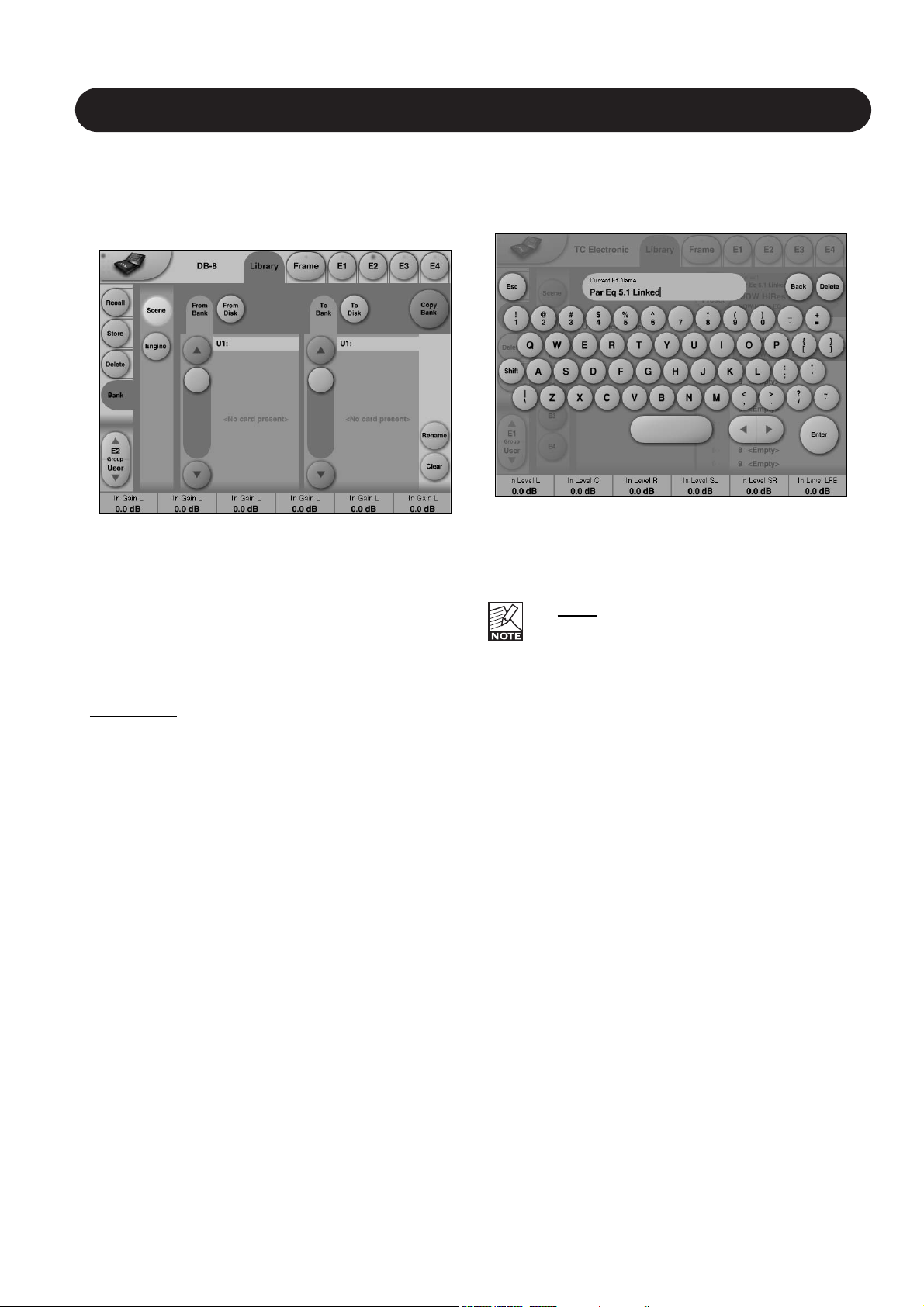
Naming Presets
All user preset types - Scene, Routing or Engine level
can be renamed.
Basic operation
• Press the Name field. A keyboard will pop up.
• Type in the new name.
• Press Enter.
The preset is not stored when the keyboards Enter
key is pressed. Only the name is entered.
To store you MUST press the red Store key on the
Store page.
The previous accessed display will always be present
beneath the keyboard. Current Fader values will be
displayed and faders can be used to adjust parameter
values.
Library - Bank
Via the Library Archive page you can copy Scene,
Routing and Engine banks to and from a 3.5” disk or a
PCMCIA card.
Basic Operation
Recalling/Storing to and from a 3.5” floppy or a PCMCIA
card is handled as a complete User bank transferal.
• Press Scene, Routing or Engine to select preset bank
type.
• Select “from” and “to” depending on your choice.
• Press Copy.
Scene/Routing/Engine Banks
T
o/From Bank
Banks can be Scene, Routing, Engine, or Card banks if
these are present on a PCMCIA card placed in the
Mainframe front panel.
T
o/From File
File banks can be Scene, Routing or Engine Banks located
on a 3.5” disk present in the Mainframe.
Copy
Press to activate copy function between the selected
Banks.
Rename
Press to rename selected bank via the Naming pop-up
display.
Clear
Press to clear the selected Bank. You will be asked to
confirm your choice to avoid unintended deletion.
Page 9

9
LIBRARY - DELETE
Library - Delete
For convenience it is possible to “clean up” the User
bank by deleting individual presets.
On the Delete page the following banks are available
for delete operations.
Scene
Allows you to delete presets in the following bank.
• User (Preset #0-49)
Routing
Allows you to delete presets in the following bank.
• User (Preset #0-49)
Engine
Allows you to delete presets in the following bank.
• User (Preset #1-99)
Deleting a Preset
• Press Delete (side tab) and select level by pressing
Scene, Routing or Engine.
• Select the preset to delete using the on-screen “Slider”
to select a preset
• Press the Delete key to delete the preset.
Parameter Fader
values present in
the last modified
Engine.
Library, Frame and Engine selectors
Fader
Group
Selector
Function
Select
Tabs
Page 10

10
FRAME
Frame - Routing
Introduction
The Routing page is the patch-bay of the System 6000
Mainframe. All routings of physical Inputs/Outputs as well
as internal routing between the Engines are setup here.
The understanding of this page is therefore essential to
operating the System 6000.
To access the Routing Page:
• Press Frame (upper tab)
• Press Routing (side tab)
• Press Route to enable routing facilities
This is the p
age where you:
• Have the overall view of all I/O’s
• Route physical Inputs to Engine Inputs
• Route Engine Outputs to physical Outputs
• Access Input and Output meters
Routing Inputs
• Press the Route key to select route operation.
• Press ENGINE 1 to 4 to select the Engine you
wish to route
• Select a physical Input or another Engine's Output using
Fader 1
• Select Engine Input using Fader 2
Routing Outputs
• Press the Route key to select Route operation
• Press Engine 1 to 4 to select the Engine you wish to
route
• Select an Engine Output using Fader 5
• Select Physical Output using Fader 6
The I/O possibilities are as follows
• It is possible to connect any physical Input to several
Engine Inputs (up to 32), however, it is not possible to
connect more than one physical Input to the same
Engine Input.
• It is possible to connect all Engine Outputs (up to 32) to
one single physical Output.
• It is possible to connect an Engine Output to the Inputs
of the three other Engines.
To distribute a single Output of an Engine to
several physical Outputs:
• Route the Engine Output to a physical Output.
• Route the same Engine Output through a passive
channel of an algorithm loaded in another Engine.
E.g. channels 7 and 8 of the Toolbox-5.1.
When routing an Engine Output to an Engine Input
with the M5000 frame and no TC Icon, the Engine
Input channel number must match the Engine
Output number from where the signal originates.
E.g. Output channel 1 from Engine 1 to Input
channel 1 on Engine 2, 3 or 4.
Engine Processing Delay
Processing delay between the routed Engines
behaves as if the were external devices.
Labels
The Input/Output fields can show either meters or the
Labels/names on the Input/Output channels. To switch
between the two modes press “Labels”.
Renaming Physical Inputs and Outputs
Input and Output channels can be labeled individually. This
is a global renaming process and is accessed by pressing
System (side tab) followed by I/O and Labels. After that
follow the naming procedure described on page 6.
Meters
Engine I/O Meters
Engine I/O meters are shown at the left and right of the
large E 1-4 buttons in the middle of the display. The
number of meters shown will always reflect the number of
I/O channels in the loaded algorithm.
Frame - E1 to E4
This page holds the User group parameters for all four
Engines. Selecting User group parameters is done from the
Engine pages. Values can be altered from both the Engine
Edit pages and the page displayed above. Press the
parameter you wish to assign to the Fader located below.
Page 11

11
FRAME - SYSTEM - MAIN
Clock
Clock Mode
To be able to successfully clock your system you must
select between two basic ranges of Sample Rates. We call
these ranges Normal and Double mode. Double mode
covers Sample Rates 88.2 and 96kHz, Normal mode
covers 32, 44.1 and 48kHz. If incorrect mode is selected
when trying to lock, no lock status can be obtained.
Normal Rate:
32, 44.1 or 48kHz are supported.
When Internal mode is selected 44.1 or 48kHz are
supported
Double Rate:
88.2 or 96kHz are supported.
Clock Master
Select the Clock source for the complete Mainframe,
including all Engines and all I/O’s.
Select between:
Internal, Wordclock, AES 1-2, 3-4, 5-6 or 7-8.
A lock up to an external source will take approx.. 7 sec.
It is not necessary to have the Physical Input
routed to an Engine Input to have the clock accepted.
Internal Clock Rate
The internal Clock Rate can be set to 44.1 or 48kHz when
Clock Mode is set to Normal and 88.2 or 96kHz when
Clock Mode is set to Double.
Locked Clock Rate
The Clock Rate to which the Mainframe is currently locked.
If the incoming Sample Rate is +/- 0.2% away from 32,
44.1, 48, 88.2 or 96kHz the Sample Rate will be shown
with an added "!" to indicate that the Sample Rate is
inaccurate.
Detected Sample Rate
This is a read-only parameter indicating the actual incoming
Sample Rate. The tolerance of this detection is +/- 10Hz.
An incoming Sample Rate of 44.056kHz will be detected as
approx. 44.06kHz and the system indicates the Locked
Clock Rate 44.100kHz.
The system will lock to and reject jitter at any Sample Rate
between:
• 30 - 34kHz
• 42.5 - 45.5kHz
• 46.5 - 48.5kHz
• 85 - 91kHz
• 93 - 97kHz
Sample Slip
Monitors the Clock status of the incoming AES/EBU
Inputs and indicates whether the incoming Clock is in sync
with the mainframe Clock settings. Three states of
incoming clock can be indicated.
Locked
The Input is in Sync with the Mainframe.
Sample Slip
The Input is out of sync with the Mainframe. Check that
there is only one
Master Clock source in your setup.
Not
Available
Indicates no connection available.
SMPTE
Basic Operation
• Press parameter to select and use Fader 6 to set value.
Reader Enabled
On/Off switch for the System 6000 SMPTE Reader.
Frame Rate
Range: 24 FPS, 25 FPS, 29.97 FPS,
30 Drop FPS, 30 FPS.
Running Status
The small field in the top left corner of the numeric display
will state “Running” when SMPTE clock is running.
Page 12

typically used if your sending MIDI device cannot send
Controllers 0 and 32 as described above.
Normal mode
In Normal mode all banks can be accessed for program
changes. Bank selection is done via Ctrl 0 (MSB) and
Ctrl 32 (LSB):
• Controller 0 must be set to 0 in all cases.
• Controller 32 value must match the bank number you
wish to address according to the table below.
Ctrl 32 value 0 - F1: Reverb A (Music Stereo)
Ctrl 32 value 1 - F2: Reverb B (Music Stereo)
Ctrl 32 value 2 - F3: Reverb (Music Surround)
Ctrl 32 value 3 - F4: Reserved
Ctrl 32 value 4 - F5: Reverb A (Film Stereo)
Ctrl 32 value 5 - F6: Reverb B (Film Stereo)
Ctrl 32 value 6 - F7: Reserved
Ctrl 32 value 7 - F8: Reverb (Film Surround)
Ctrl 32 value 8 - F9: Reserved
Ctrl 32 value 9 - F10: Mastering
Ctrl 32 value 10 - F11: Reserved
Ctrl 32 value 11 - F12: Pitch & Delay
Ctrl 32 value 12 - F13: Reserved
Ctrl 32 value 13 - F14: M5000 Presets
Ctrl 32 value 32 - User bank
Ctrl 32 value 64 - Card Bank 1
Ctrl 32 value 65 - Card Bank 2
Ctrl 32 value 66 - Card Bank 3
- - - - -
Ctrl 32 value 73 - Card Bank 10
Example:
You wish to recall preset 10 from the Reverb (Music
Surround) bank. According to the table above:
• Set Ctrl 0 to “0” and Ctrl 32 to “2” and send program
change no 10.
SysEx Device ID
Range: 0 to 126
Select SysEx ID for the Mainframe.
12
FRAME - SYSTEM - MAIN
MIDI Setup Page
Introduction
MIDI Channels
To recall presets for Scene, Routing and Engines 1 to 4
you must first setup individual MIDI channels for these
categories.
In the example above we have setup MIDI channels 1 to 4
for Engines 1 to 4 respectively; channel 5 to access Scene
presets and channel 6 to access Routing presets.
Bank Mode
The Bank mode settings determine the destination bank of
the received program change on the specified MIDI
channels.
Normal mode:
This mode requires that the external sending MIDI device
can send both Controller 0 and 32 in addition to MIDI
program changes. This is an essential feature to recall
presets from a device holding more than 128 preset
location. (see table in next column for details)
Factory and User mode:
These modes will force any incoming program change to
access either Factory or User banks directly and are
Page 13

13
FRAME - SYSTEM - MAIN
MIDI Control Page
On MIDI Control Page the following options are
available:
Read Program Change
Select whether the Frame should read incoming program
changes or not.
Send Program Change
Select whether the Frame should send program changes to
MIDI out when presets are recalled via TC Icon or the TC
Icon Software editor.
Read Control Change
Select whether the Frame should Read Control Changes
messages.
Send Control Change
Options here are Single (7 bit) or Double (14 bit) precison.
Read SysEx - Send SysEx
These two parameters determine whether the Frame
should read and send SysEx.
Page 14

14
FRAME - SYSTEM - MAIN
Single precision:
FADER 1 MIDI CC 70 Sound Controller 1
FADER 2 MIDI CC 71 Sound Controller 2
FADER 3 MIDI CC 72 Sound Controller 3
FADER 4 MIDI CC 73 Sound Controller 4
FADER 5 MIDI CC 74 Sound Controller 5
FADER 6 MIDI CC 75 Sound Controller 6
Double precision, LSB:
(Note that both LSB and MSB must be sent for double precision)
FADER 1 MIDICC 48 General Purpose Controller #1
FADER 2 MIDICC 49 General Purpose Controller #2
FADER 3 MIDICC 50 General Purpose Controller #3
FADER 4 MIDICC 51 General Purpose Controller #4
FADER 5 MIDICC 52 Undefined
FADER 6 MIDICC 53 Undefined
Double precision, MSB
(Note that both LSB and MSB must be sent for double precision)
FADER 1 MIDICC 16 General Purpose Controller #1
FADER 2 MIDICC 17 General Purpose Controller #2
FADER 3 MIDICC 18 General Purpose Controller #3
FADER 4 MIDICC 19 General Purpose Controller #4
FADER 5 MIDICC 20 Undefined
FADER 6 MIDICC 21 Undefined
External MIDI Control - of Fader Parameters
From software version 2.5, all fader assignable parameters can be remote controlled via MIDI Control Change Messages.
To be able to control Faders you must create a dedicated Fader User Group holding these parameters. Page 20 in this
manual section explains how to create User Fader Groups.
Single Precision - Double Precision
We support both single (7bit) and double precision (14 bit) Controller Data, but you should notice that best resolution is
achieved using 14 bit Controller Data. By controlling parameters with Single precision you will be able to control in 128
steps for a complete parameter range. For most applications this will be quite fine and this is also the precision most
external controllers and especially sequencers support. This is called 7 bit precision.
However, System 6000 supports the 14 bit precision standard that has a considerably higher resolution: 128x128=16384
steps.
To achieve this resolution via an external fader control the external controlling device must be able to handle two
controllers at the same time on the same MIDI channel. The scheme below shows which controllers to assign to which
Faders for both Single Precision and Double Precision situations.
MSB value indicates the actual double parameter change. So sending a LSB will not change
the value, but only cache this value for later use when receiving the MSB part.
The LSB must therefore be sent before the MSB.
Page 15

15
FRAME - SYSTEM - MAIN
Setting up
Make sure to select MIDI channel settings corresponding to
the channels your external controller is using for each
Engine. This is setup in the MIDI Setup page.
A
few things to take into consideration when using the TC
Icon Faders to record automation into your sequencer:
Make sure that the record enabled MIDI track does not
echo back the MIDI Input to the System 6000. Otherwise
the System 6000 will receive double MIDI CC values, which
creates a MIDI loop and un-smooth automation data.
The following example explains how to avoid this on a
Protools System. If you are using other systems you should
look for similar features or use the feature introduced in
System 6000 Software version 2.5 (see below):
Example
• In DigiDesign Protools in the MIDI menu you disable MIDI
THRU. This way when the track is record enabled, the
incoming events are not echoed to the Output.
• In case your sequencer or MIDI data recorder does not
offer the possibility to mute the track while recording you
can use a new feature to avoid a MIDI loop with the
System 6000.
The new function is added to System 6000 software
version 2.5 and is located on the System/MIDI page.
The controls used are called Read/Send-Control/Program
Changes, and determines whether you want to send, or
receive MIDI Control Change/Program Changes.
This is especially helpful, in case you are using the ICON
faders to record the MIDI CC data to your external
application.
How to record/playback MIDI data into/from DigiDesign
Protools 5.x ?
Recording
• On the TC Icon go to the Frame/System/Main/MIDI page,
and set up the Send/Receive parameters as follows:
Send CC : ON
Receive CC : OFF
• Make sure that in the Protools MIDI menu, the MIDI
THRU function is disabled to avoid a MIDI loop while in
recording mode (as explained in the previous column).
• Make sure you have your MIDI Input devices correctly
configured in Protools. Set MIDI Thru to OFF in the MIDI
menu.
• Create new MIDI Track
• Set the MIDI Output channel of that track in the Mixer
window
• Add New MIDI controllers, and choose the right
Controller numbers from the list (see next page)
• Record the MIDI automation data using the Icon faders
or external MIDI faders/knobs
Playing Back
• On the TC Icon go to the Frame/System/Main/MIDI page,
and set up the Send/Receive parameters as follows:
Send CC : OFF
Receive CC : ON
• Play back
For more info on MIDI recording in Protools, please
refer to your Protools Manual and Digidesign.
See next page for overview of Single and Double
precision controller numbers.
Page 16

16
FRAME SYSTEM MAIN
Net
Software versions
Current installed software versions.
Network Identifier
Press the field “Network Identifier” to enter a name for the
Mainframe. This is the global TC network name for the
frame. By giving the frame a specific name it will be easier
to identify the frame when hooked up in a network with
several frames.
Error Indication
If “no Lock” is acheived or “Sample Slip” situations occur
this will be indicated via the small red dot in top of the
Frame Tab.
Press the Frame Tab and you will be guided to the exact
page where you can correct or compensate for these
situations. Simply press the “red” tabs.
Page 17

17
FRAME - SYSTEM - I/O
Via the I/O page the following operations are handled:
• Settings for the DSP card
• Settings for up to three I/O cards
• Labeling of all physical Input and Output channels
Basic operation
If more than one mainframe is connected:
• Press the Icon symbol in the upper left corner to enter
the Select & Setup pages
• Select which mainframe you wish to setup
• Press the Icon symbol once again and and select
System - I/O as illustrated above
I/O - SETUP
The following Setup page will appear in:
Frame/System/I/O/Setup when an AES-8 card is
installed.
Analog Input - Digital Input
With an AES-8 card installed in a Mainframe, you must
select whether Input channels 9 through 16 should be
digital or analog.
When Digital Input is selected:
Input channels 9-16 will be the AES-8 card.
When Analog Input is selected:
Only analog Inputs are available!
If an ADA-24/96 card is installed in slot A analog Input
channels 9-10 are available.
If ADA 24/96 cards are installed in both slot A and C,
analog Input channels 9-10 and 13-14 are available.
Please note the following:
• No Inputs on the AES-8 card are available when analog
Input is selected.
• Digital Input must be selected to activate AES-8 card
Input channels 9-16 even if no ADA 24/96 cards are
present.
• Outputs 9-16 are always available. If ADA-24/96 cards
are installed, they will output simultaneously with the
AES-8 Outputs on channel 9-10 (Slot A) and 13-14 (Slot C).
I/O - DSP
Status Bit
Status bit information can be set separately for each of the
AES Outputs.
Options are:
AES/EBU : Professional usage of Status bits.
S/PDIF : Consumer usage of Status bits.
Clock Status - Sample Slip Detection
Input 1-2, Input 3-4, Input 5-6, Input 7-8
Input 9-10, Input 11-12, Input 13-14, Input 15-16
Monitors the Clock status of the incoming AES/EBU
Inputs and indicates whether the incoming Clock is in sync
with the mainframe Clock settings. Three states of
incoming clock can be indicated.
Locked
The Input is in sync with he Mainframe.
Sync Error (Red)
The Input is or has been out of sync with the mainframe.
Press the Reset key to see if Sample Slips are still
occurring. - If so - Check that there is only one Master
Clock source in your setup. This monitoring function is
excellent when trying to determine which connected device
is out of sync.
No Input
Indicates no connection available.
Page 18

I/O - Slot A, B & C
This is where you setup card specific parameters.
Parameters are only available when a I/O Card is detected.
For the ADA 24/96 card the following parameters
can be set.
Level In
Changes the analog nominal Input level between +6dBu
and +30dBu in 6dB increments.
The analog Input level enables you to match the M6000
Input to the Output of e.g. your mixer. If the nominal
operating level on your mixer is e.g. +4dBu and you select
+12dBu on the Level In parameter you will have a
headroom of 8dB. If you select +16dBu in the Level In the
headroom will be +12dB, and so forth.
Level Out
Changes the analog output level between +6dBu and
+24dBu in 6dB increments.
Output Connection
Select the type of connection you are using on the Output
of the card. Select between:
Balanced or unbalanced (with signal on pin 2 or pin 3).
If you are connecting unbalanced cables to the
Outputs when Outmode is set to “Balanced”,
the Outputs will be muted/un-muted
sequentially via a goldplated short circuit
protection relay. This is intentional and will not
cause damage to any device.
Balanced/Unbalanced Operation
Unbalanced operation
Some mastering studios prefer unbalanced wiring.
Please read these notes for optimum performance.
Preferably, balanced cables should be used on Inputs and
Outputs even for unbalanced setups.
Input
Pin 2 hot, pin 3 connected to reference (shield) at the
Output of upstream device.
18
FRAME - SYSTEM - I/O
Output, pin 2 selected
Pin 2 hot, pin 3 connected to reference (shield) at the Input
of downstream device. In this mode pin 3 acts as a
reference Input for the ADA2496 Output stage and should
not be left unterminated.
This mode will not work properly with balanced
inputs unless wiring is compensated as described. If
wired properly, this is the optimum output mode for
feeding unbalanced devices.
Output, pin 3 selected
Pin 3 hot, pin 2 not needed. In this mode pin 2 and pin 1
carry the same output reference.
This works with balanced inputs using 1:1 wiring,
but balanced mode should be selected if driving a
balanced input.
Filters
When operating the mainframe in normal Sample Rates
(32 - 48kHz) you can select different down- and
up-sampling filter types. The AD and DA conversions are
always performed in high-sample domain (88.2 to 96kHz).
Afterwards the digital down- and up-sampling is performed
in the digital domain using a local DSP on the ADA24/96
card. Select filter type according to the source material you
are working on.
Filters
Chose between - Linear, Natural, Vintage, Bright and
Standard (Std).
"Linear" filter
These filters are linear-phase and non-aliasing (the stopband starts below the Nyquist frequency). The pass-band
response is extremely smooth and non-equiripple,
extending beyond 20kHz. With the "Linear" filters you'll
have a hard time discriminating between the sound of the
conversion chain and direct analog, even at 44.1kHz!
"Natural" filter
Based on the "Linear" filter class, but with a carefully
adjusted non-linear phase response, these filters obtain an
almost "better-than-live" reproduction of space while
retaining crystal-clear imaging and absolute tonal neutrality.
The "Natural" filters too are non-aliasing.
"Vintage" filter
Based on the "Natural" filters, here we've added a bit of
warmth and roundness to the treble by introducing a
smoother "tube like" roll-off. This filter would be an
exceptionally good choice when mastering material that
seems too hard in the high-end frequencies.
These filters too are non-aliasing and non-linear phase.
Page 19

19
FRAME - SYSTEM - I/O
If ADA 24/96 cards are installed in both slot A and C,
analog Input channels 9-10 and 13-14 are available.
Please note the following:
• No Inputs on the AES-8 card are available when analog
Input is selected.
• Digital Input must
be selected to activate AES-8 card
Input channels 9-16 even if no ADA 24/96 cards are
present.
• Outputs 9-16 are always available. If ADA-24/96 cards
are installed, they will output simultaneously with the
AES-8 Outputs on channel 9-10 (Slot A) and 13-14 (Slot C).
I/O - Labels
All physical Inputs and Outputs can be named/renamed.
Enter the Titles page by pressing the tabs System and
Titles. Press any of the 16 Inputs/Outputs and the Naming
display will pop up. Enter adequate name for the
Input/Output and press Enter.
The names will be displayed on the Frame-Routing page.
"Bright" filter
These filters are something entirely different: Ultra-short
impulse response, linear phase and quite a bit of deliberate
aliasing produces a "digital" and slightly aggressive sound
adding plenty of top-end life to e.g. Rock and Techno
recordings, or giving you the feeling of air you need when
you are mastering a somewhat dark sounding source
material.
"Standard" filter
This filter emulates the response of typical mid-end
converters: Equiripple half-band filters that are precisely
6dB down at the Nyquist frequency.
These filters are available in 44.1 and 48kHz.
Softclip
The Softclip algorithm runs in the 96kHz domain right after
the AD conversion before the down-sampling filter.
AES-8 Card
Slot B with an AES-8 card installed
The following Setup page will appear in:
Frame/System/I/O/Setup when an AES-8 card is
installed.
Analog Input - Digital Input
With an AES-8 card installed in a Mainframe, you must
select whether Input channels 9 through 16 should be
digital or analog.
When Digital Input is selected:
Input channels 9-16 will be the AES-8 card.
When Analog Input is selected:
Only analog Inputs are available!
If an ADA-24/96 card is installed in slot A analog Input
channels 9-10 are available.
Page 20

20
FRAME - SYSTEM - LICENSES
The I/O Labels are global and are not affected by
preset changes.
Licenses
The System 6000 holds numerous algorithms as a part of
the standard package. Various other algorithms are
available. These algorithms require purchasing of Licenses.
The License types and their status (active/inactive )
available with the installed software are listed under
“License Type”. (see above)
To try out one or more of the licenses a time limited Demo
Key can be achieved by contacting TC Electronic.
Press the Get Demo Key and follow the instructions.
Page 21

21
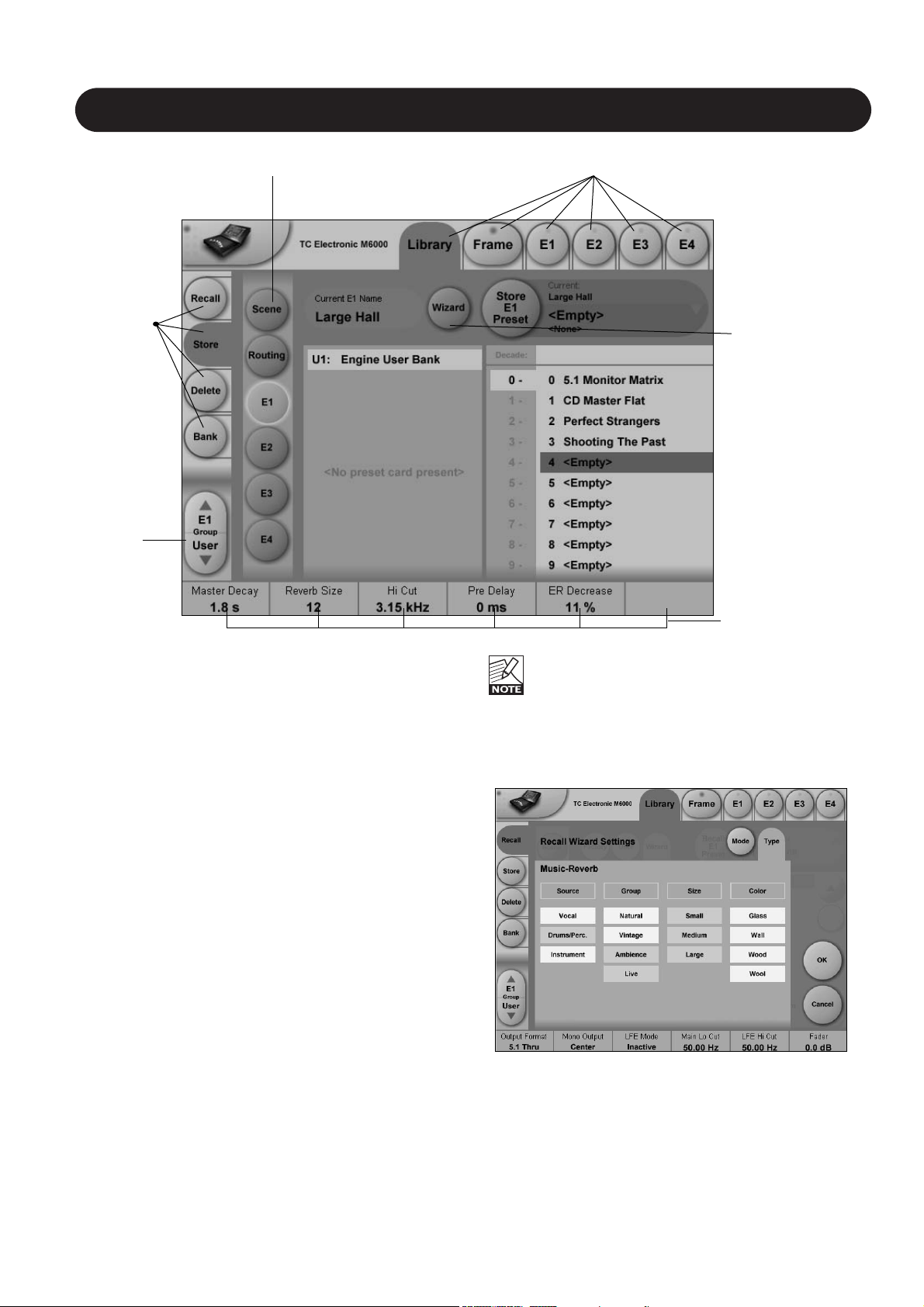
ENGINE - EDIT PAGE
Fader Group
Parameters/
Value fields
Output
Meters
Display
function
indicator
Input
Meters
Library Frame and Engine SelectorsName of the currently
recalled preset
Fader
Group
Selector
Parameter
Pages
Link key
Fine Adjust
Mode
The Engine 1-4 Edit Pages
This is where you edit algorithm parameters.Parameters in
several algorithms are distributed on different pages. As
illustrated above the MD 5.1 has 6 pages: Main, Setup,
Expander, Compressor, Limiter and Output. Depending of
the quantity of parameters represented in the groups one
or more groups will be displayed.
Basic operation
• Press E1 to E4 to select Engine. Parameters for the
recalled algorithms are instantly available for editing.
• Select a parameter group. In the example above - a MD
5.1 algorithm - the groups are Main, Setup,
Expander, Compressor, Limiter and Output.
• All parameters are assigned to the Fader Groups. Select
Fader Group using the Fader Group selector.
• Press any parameter and it is assigned to Fader 6.
Fader User Group - Assign key
By pressing the Fader Group Selector Up key you enter
the User group. In this group you can assign any
parameter to any Fader. The User Fader group is stored
with a preset.
• Press the Link key.
• Select the Fader you wish to link a parameter to, by
pressing the field just above the fader.
• Press the parameter you wish to link to the selected
fader.
Bypass
The Bypass key will respond in different ways depending
on the recalled algorithm. See specific algorithm description.
In some algorithms the Bypass will work as a mute
function.
Naming a Preset
• Press the Name field. A keyboard will pop up.
(See the “Naming display” section).
• Type in the new name.
• Press Enter.
Parameter value - Fine Adjust
Any parameter value can be adjusted in two accuracies.
A Normal and a Fine Adjust - mode. To switch between the
two modes press the Value Fields above the faders.
As shown in the illustration the Fine Adjust mode will be
indicated with two triangles in the value field.
Page 22

22
ICON SETUP
Icon User Interface
Go to the Select & Setup pages pressing the TC Icon
key in the upper left corner.
Press SETUP (upper tab) and UI (side tab) to enter the
setup page for the TC Icon display.
TC Icon Display Parameters
In this display you setup various parameters regarding the
appearance of the display as well as the Fader Touch
Sensitivity.
Display Brightness
Adjust the brightness of the display using either the Arrow
cursors or simply drag the “Adjust handle”.
Show Mouse Cursor
Press to show mouse/pointer position.
Calibrate Display Touch
For optimal performance the Touch Screen will at times
need to be calibrated. Press and follow instructions to
Calibrate the Touch Screen.
Fader Sensitivity
To avoid accidental movement of the faders they are
sensitive to humidity and will only respond when touched
by your skin.
Enable Fader
Touch
Enables touch sensitivity of the Faders.
AC/DC Sensitivity
Sets the Faders sensitivity to AC and DC. Adjust these
handles to achieve optimal performance in your
environment.
Icon Color Scheme
Color Scheme
Select the Color scheme of your choice. Depending on the
surrounding light conditions different schemes may be
more appropriate than others.
Page 23

23
SMPTE
Auto Edit Page
In the Auto Edit page all automation Events are listed and
handled.
Keep
Press to save the Event List locally on the Icon. It is possible
to save one Event List on the Icon. Additional cue-lists can
be stored and recalled on floppy disks on the Mainframe.
The Keep key will turn red as soon as any editing of the list
has taken place, indicating that you must press to save the
list.
This key corresponds/is the same, as the Keep key located
on the File page. (see following page)
Write
When enabled any program change is written to the
SMPTE Event List. This can be. e.g Engine, Routing or
Scene recalls.
Read
When enabled the Event list will be executed according to
incoming SMPTE clock. Read and Write functions can be
activated simultaneously.
General Read and Write status is given in the
Icon Tab in the left corner.
Save
Press to save the Event list. The Save key will turn red as
soon as any editing of the list has taken place, indicating
that you must press to save the list.
This key corresponds/is the same, as the Save key located
on the file page. (see next page)
Be aware that until Save is pressed Edited SMPTE
information is not yet stored in the Event list. For
convenient indication the Save key will be red as
soon as any alteration of the current Event list is
present.
Cursor
The white triangular cursor always indicates the current
clock position in relation to the Event List.
Event Parameters
For each Event the following parameters are available.
Time - indicates the SMPTE time at which the Event
takes place.
Device - indicating on which Device Mainframe the
Event is taking place. Device numbers 1-8,
corresponds to the Device position at the
Select page.
Event - states the occurring Event at the given time.
Modify
Press this key to access Event parameters for the currently
selected Event. (see further description below)
Insert
Press to insert an Event (see further description below)
Delete
Press to delete the selected Event.
Modify/Insert - Edit
Event Settings
Operation
• To access Event settings press Modify in the Edit page.
• Setup all parameters for the Event you are about to
Modify or Insert.
• Press OK to confirm.
Time
The time where the Event being Modified or Inserted
is taking place.
Step/Adjust
Range: Frame, 1 Second, 10 Seconds, 1 min.,
10 min. or 1 hour.
Use the Step parameter to select Adjust range and the
Adjust parameter to increase/decrease the time.
Device
Page 24

24
SMPTE
This parameter selects which Mainframe connected to the
LAN you are working on. Device numbers 1-8, corresponds
to the Device position at the Select page.
Preset Type
Selects whether the preset Event you are working on is a
Scene, Routing, Engine or a System preset.
Bank
Select the bank related to the preset you are about to
setup/recall via SMPTE.
Preset
Select the preset from the selected bank
File
Current List
Keep
Press to save the Event List locally on the Icon. It is possible
to save one Event List on the Icon. Additional cue-lists can
be stored and recalled on floppy disks on the Mainframe.
The Keep key will turn red as soon as any editing of the list
has taken place, indicating that you must press to save the
list.
This key corresponds/is the same, as the Keep key located
on the Edit page. (see previous page)
Revert
This “Undo” function allows you to revert the to the last
saved SMPTE Event list. This is the List that is stored
locally on the TC Icon.
Clear
Press Clear to delete the entire SMPTE Event list present
in the TC Icon.
Remote device disk drive
Event lists can easily be organized and saved to a Floppy
disk in the Mainframe.
Mainframe selection is done in the Auto Edit page.
Get List
Press to get a list of all SMPTE Event lists stored on the
floppy disk located in the Mainframe.
New
Press New to create and name a new Event list in the
floppy disk in the Mainframe.
Save
Press to save the current Event list to the disk.
Load
Press to load Event list from disk.
Delete
Press to delete selected Event preset from the
Event Preset list.
Options
Automation Timecode Options
Master Sync Device
Select which of the Mainframes connected on the LAN you
wish to act as Master Clock.
Start Of Daytime
Range: 23:00:00:.00 or 00:00:00:00
If the SMPTE time code present on your tape media or film
does not start exactly at the beginning of the tape the
23:00:00:00 setting would be a good choice to keep
chronological order in the Event List.
Page 25

25
TC ICON SOFTWARE EDITOR
The TC Icon Software Editor is a fully operational software remote control for the System 6000
All functions available via the TC Icon hardware version are also available via the Software Editor.
From Software release 2.5 a TC Icon Software Editor is availble for Mac operating systems as well as Windows.
A network adapter must be installed in your computer for connection to a Mainframe.
To install the TC Icon Software Editor, please follow the instructions in the Hardware & Installation chapter.
The Hardware & Installation chapter also explains how to setup TCP/IP addresses etc.
 Loading...