


1
ALGORITHMS - CONTENTS
In
Introduction
Table of Contents . . . . . . . . . . . . . . . . . . . . . . . .1
Introduction . . . . . . . . . . . . . . . . . . . . . . . . . . . . .2
Algorithms
ATX/DTX . . . . . . . . . . . . . . . . . . . . . . . . . . . . . . .3
Multiband 5.1 . . . . . . . . . . . . . . . . . . . . . . . . . . .9
MDX 5.1 . . . . . . . . . . . . . . . . . . . . . . . . . . . . . .15
Downconvert 5.1 . . . . . . . . . . . . . . . . . . . . . . . .25
Upconvert 5.1 . . . . . . . . . . . . . . . . . . . . . . . . . .29
Upcon & Upcon+ . . . . . . . . . . . . . . . . . . . . . . .33
EQ/Delay 8 . . . . . . . . . . . . . . . . . . . . . . . . . . . .41
Preset List . . . . . . . . . . . . . . . . . . . . . . . . . . . . . .a
TC Electronic, Sindalsvej 34, DK-8240 Risskov
tcdk@tcelectronic.com
Algorithms DB8/DB4 Rev 1.60
English version
2
INTRODUCTION
Introduction
This chapter contains lists of available factory presets (defaults) for both Scene and Engine set-ups. Also comprehensive
information about the specific processing configurations (algorithms) in DB8 and DB4 are available. If you are looking for
detailed descriptions for the individual parameters in the processors, this chapter is the place to look.
Compatibility: Presets are fully compatible between DB4 and DB8 units.
Scene, Routing and Engine presets may be shared between the units using Floppy Disc, PCMCIA Card or Banks via
Network. However, Engine 3 and Engine 4 settings are disregarded by a DB4.
Channel Distribution In
Surround Algorithms
To best comply with the channel allocation used by most
digital AES-format equipment the Input/Output channels on
surround algorithms are allocated as follows:
1 Left
2 Right
3 Center
4 LFE
5 Left Surround
6 Right Surround
These channel allocations comply with the following
standards:
• ITU-Recommendation ITU-R BR.1384, Parameters for
International Exchange of Multichannel
Sound Recordings, 1998
• SMPTE 320M-1999, for Television - Channel
Assignments and Levels on Multichannel Audio Media
• Surround Sound Forum Recommended Practice
SSF- 02/1-E-2 (3-5-99), Multichannel Recording Format,
Parameters for Programme Interchange and
Archiving, Alignment of Reproduction Equipment
Grouping the Inputs/Outputs this way ensures optimal
flexibility for further external processing and archiving,
when working on setups following the above mentioned
standards.
It is, however, worth noticing that total routing-flexibility
of
physical Inputs/Outputs to Engine Inputs/Outputs is
available on DB8/DB4 via the Routing page.
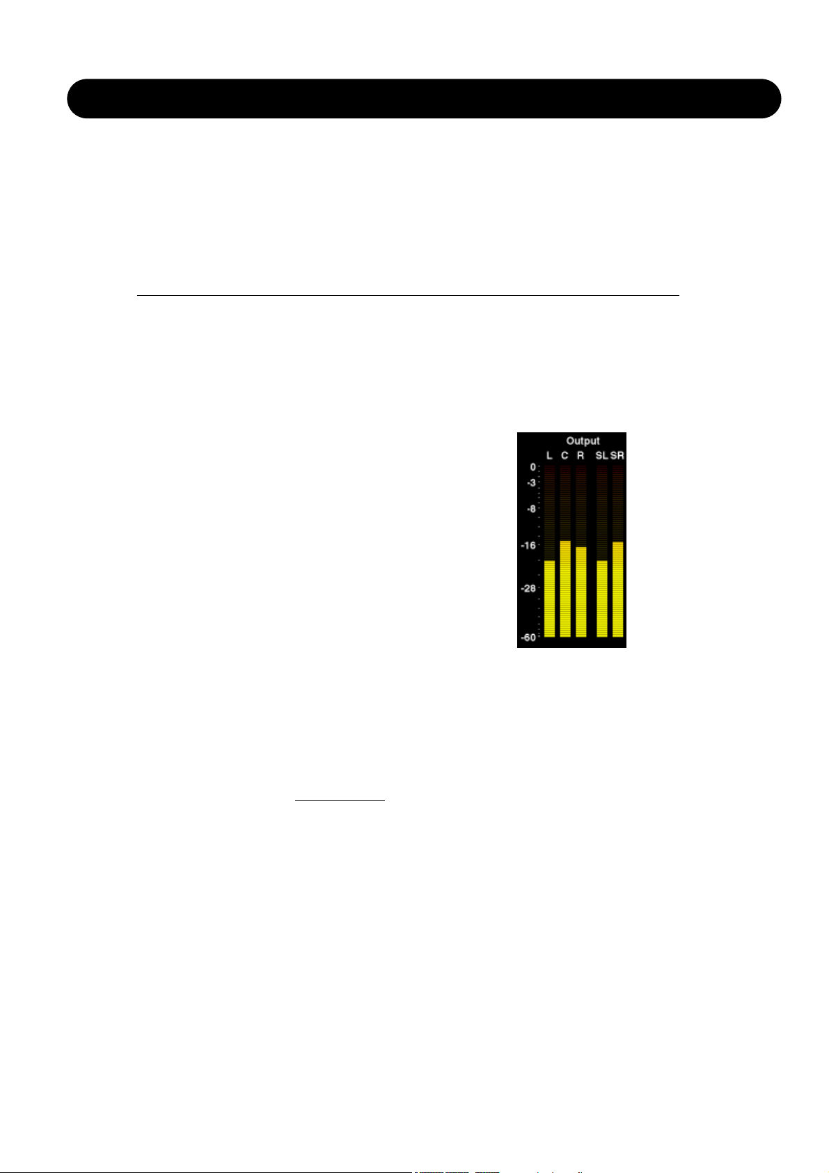
Metering In the Engine Edit Pages
For logical channel metering in the various surround
algorithms, the meters on the Engine Edit pages are
displayed in the following order.
Left - Center - Right - Left Surr. - Right Surr. - LFE
We believe that by displaying the meters on the Engine
Edit pages in the same order as your speakers are
physically placed, the most intuitive metering of channellevels is achieved.
3
ATX/DTX
Introduction
This processor is a comprehensive, high quality Loudness
control, Level optimizer and Peak Limiter. It can be
configured as Stereo, Wide Stereo or Dual Mono. The
processor uses 48 bit processing for extremely low
distortion and wide dynamic range, and oversampled peak
limiting on the Output.
The ATX/DTX algorithms can be operated in three
distinctively different modes:
- Stereo. In this mode the Loudness, EQ and Multiband
sections operate in tandem: Whatever gain change is
applied to one channel, is applied to the other. Also,
many parameters have mutual left and right controls.
- Dual Mono. In this mode the Loudness, EQ and
Multiband sections treat the two Input signals completely
independently.
- Stereo Wide. In this mode the apparent width and image
of stereo signal can be altered simultaneously with
controlling loudness and peak level. The left and right
signal is internally de-composed into an M(Mono) and
S(Stereo) component, and reverted to left and right
signals before peak limiting on the Output.
DTX/ATX
The algorithm previously known as Multiband-2 is now split
into DTX for digital broadcast and ATX for analog
broadcast. The ATX is high res, low latency loudness
control algorithm with adaptive emphasis limiting for
feeding analog transmission. The variations between ATX
and DTX is found only on the Limiter page. All other pages
are therefore described as the same in the manual section.
Reference Level
Reference Level defines the standard operating level, and
scales the Threshold and Target Level parameters of the
Loudness control and Multiband section. The Threshold of
the Limiter is not influenced by this setting, but is always
relative to 0dBFS.
Typical Reference Level settings would be -20 dBFS in the
America and some parts of Asia, and -18 dBFS in Europe,
Japan and some parts of Asia.
If you wish to relate all levels to 0 dBFS, leave the
Reference Level setting at 0 dBFS.
Analog vs. Digital level
If you use analog interfacing, remember always to set the
relationship between absolute analog and digital level
before adjusting parameters in the Engines.
DB8/DB4 has analog scaling before the A to D converter
and analog scaling after the D to A converter. These
settings can be changed and stored from the user interface
on the Slot A-C screens.
Typical analog I/O level scaling would be +24dBu in the
Americas and some parts of Asia, and +18dBu in Europe,
Japan and some parts of Asia. The figure denotes the
analog level required or produced for a 0dBFS signal.
Note 1:
Be careful when changing between configurations.
Moving from Dual Mono to Stereo will result from
parameter settings of the left (or “A”) channel being copied
into the right (or “B”) channel. Going from Dual Mono to
Stereo and back to Dual Mono will therefore overwrite
original right (or “B”) channel settings.
Note 2:
In all configuration modes, linking of the Brickwall
Limiter is set separately on the Limiter page. Some
broadcasters like the sound of operating left and right
limiting without stereo coupling because they feel that it
maximizes loudness and widens the stereo image.
On dual mono sources, of course you should always
choose un-linked Limiter operation.
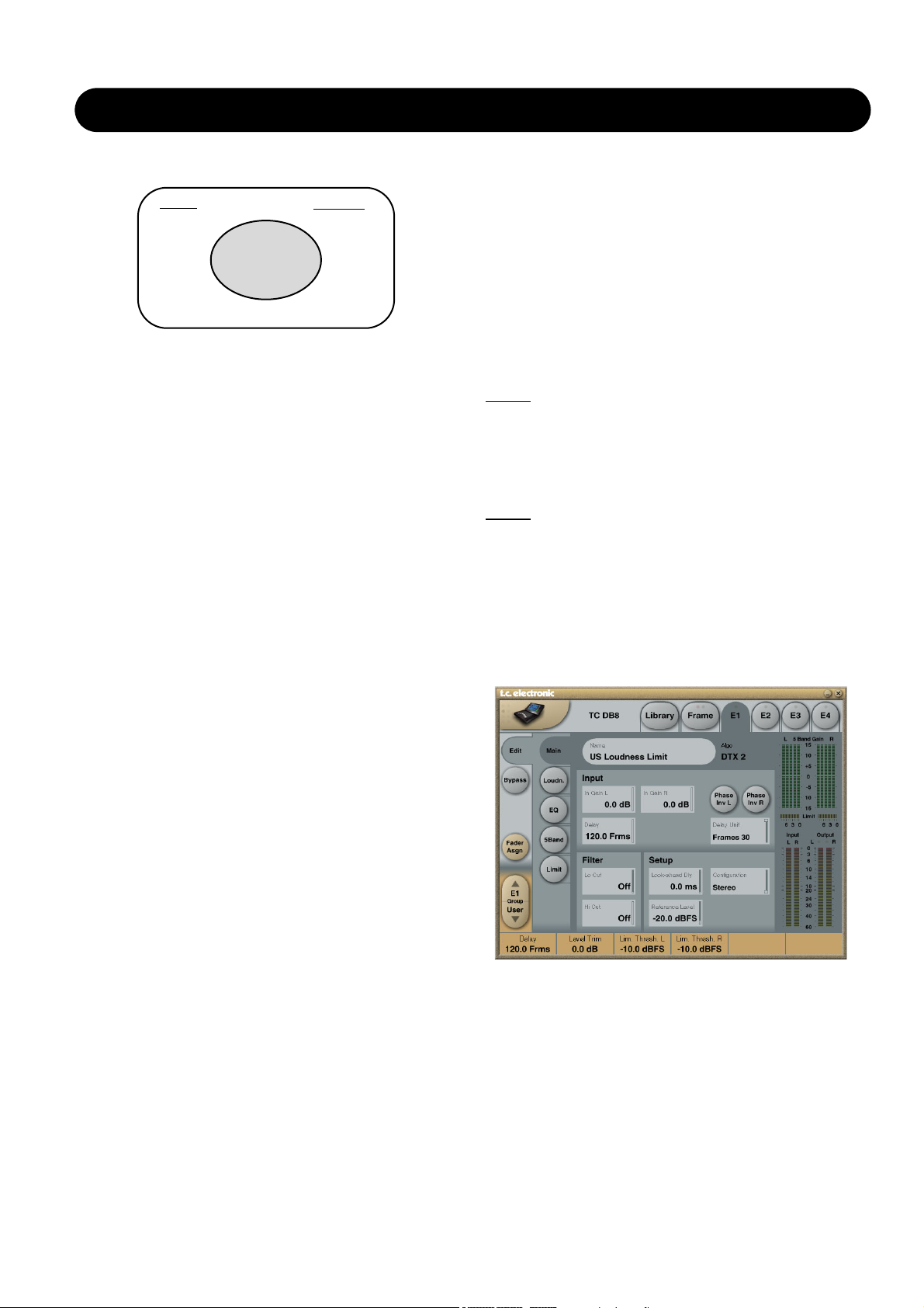
Main page
In Gain
Range: 0dB to Off
Separate level controls for Left and Right Input (A and B).
Phase Inv
Range: Normal/Inverted
Press to phase invert channels A, B or both.
Delay
Range: 0-1000ms
Delay alignment of the Input channels. Depending on
Algorithm Inputs/Outputs are distributed as follows:
E1 - E4
L
R
L
R
INPUT
OUTPUT
•
•
•
•
•
•
•
•
•
•
•
•
•
•
•
•
4
ATX/DTX
selected Configuration type, either one common Delay
setting or individual delay settings are available.
Delay Unit
Range: ms, 24fps, 25fps, 30fps
With this parameter it is possible to select which unit the
Delay parameter should be shown in. Changing this
parameter does not affect the actual delay value.
Lo Cut
Range: Off to 200Hz
Second order LoCut filter on both Inputs.
Hi Cut
Range: Off to 3 kHz
8th order HiCut filter on both Inputs.
Look ahead Dly
Range: 0-15ms
If the 5 band Compression sections is set to use a very
short Attack times (up to approx 10-15ms) overshoots may
occur. The Look Ahead function allows the DB8/DB4 to
evaluate the material just before processing and artifacts
can thereby be prevented.
Be aware that the Look Ahead delay function actually
Delays the Output signal.
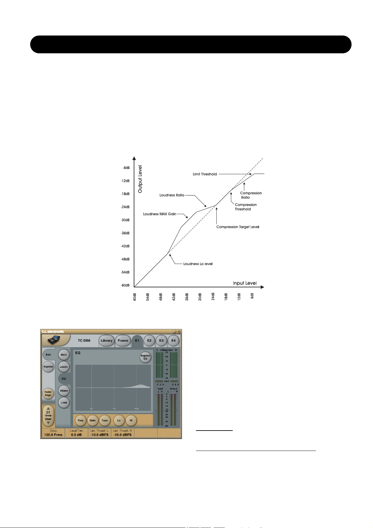
Loudness page
Target Level
Range: +10dB to -10dB
This is the level the Loudness controller will aim at on its
Output. Target Level is relative to Reference Level on the
Main Page.
Max Reduction
Range: -20dB to 0dB
This is the maximum attenuation the Loudness Control is
allowed to perform. If set to 0.0dB, the Loudness Control
cannot attenuate the signal at all. The level diagram on this
page is shown with Max Reduction set at 0.0dB.
Max Gain
Range: 0 to +20dB
This is the maximum gain the Loudness Control is allowed
to perform. If set to 0.0 dB, the Loudness Control cannot
add gain to the signal at all.
Freeze Level
Range: -10dB to-40dB
Sets the minimum level required before the Loudness
Control will start adding more gain. It would typically be set
to avoid boosting signals considered noise. The Freeze
Level parameter is relative to the Reference Level setting
on the Main page.
Freeze Hold
Range: 0 to 5 seconds
When the Input signal drops below the Lo Level, the Gain
Correction of the Loudness Section is frozen for the
duration of the Hold time. When the Hold period expires,
the Gain Correction falls back to 0dB gain.
Level Trim
Range: -18dB to + 18dB
When using the Multinband algorithm, DB8/DB4 operates
with 48 bit precision on all audio internally and it is possible
to correct loudness manually without the risk of overloads.
The Level Trim can be used for permanent off-sets or live
loudness adjustments.
Ratio
Range: 1:1.25 to 1:6
Ratio is the steering factor used when the Loudness
Control applies boost or attenuation to reach the Target
Level. The higher ratio, the more rigid steering towards the
Target Level.
Average Rate (Avg Rate)
Time constants in the Loudness Control are changed
dynamically with the Input signal based on computations by
multi-level detectors. When the Output level is close to the
Target Level, gain changes are relatively slow.
The Average Rate offsets all time constants to be faster or
slower. Values below 1dB/Sec produces a gain change
gating effect when the Output level is already in the target
zone, while values above 4dB/Sec will add density to
sound.
5
ATX/DTX
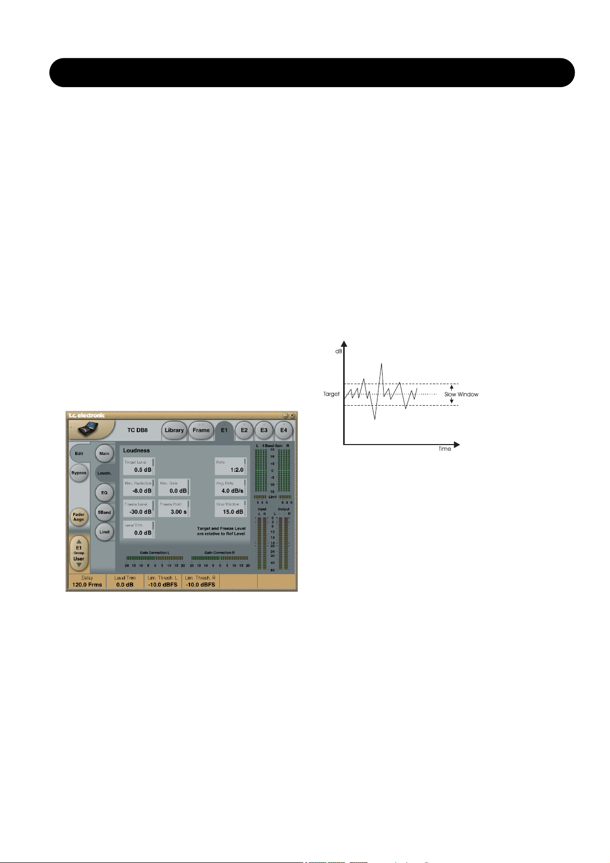
Slow Window
Range: 0 to 20 dB
The slow window is the area around the set Target Level.
Within the slow window the Loudness is only gently
controlled. When the signal exceeds the limits of the Slow
Window the Loudness is treated more radically. Depending
on the set Average Rate and Ratio.
Please see illustration on the next page!
EQ page
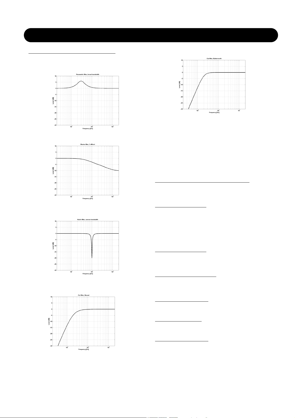
Introduction
This digital EQ features a four-band parametric EQ with
high- and low-pass filters switchable between Notch,
Parametric, Shelving and Cut filters. The needle sharp
notch filter has a range down to 0.01 octave and the
shelving filters has a variable slope, ranging from gentle 3
dB/oct over 6 and 9 to 12dB/oct. Cut filters are switchable
between 12dB/oct maximum flat amplitude (Butterworth) or
flat group delay (Bessel) types. The parametric equalizer
features a natural and well defined bandwidth behavior at
all gain and width settings:
Basic operation
• Press keys Lo, Mid and Hi to activate/deactivate the EQ
bands.
• Select Freq, Gain, Type or Lo/Hi to access all four
parameters on individual bands.
• Press Bypass EQ to bypass all four bands.
T
ype Selector
• Press Type and use faders 1-3 to select filter types.
For Lo and Hi filters select between filter types:
Parametric, Notch, Shelve and Cut.
Multiband parameter illustration
6
ATX/DTX
For the Mid filter select between filter types:
Parametric and Notch.
Parametric Filter - Broad type
Shelving Filter
Notch Filter - Narrow Type
Cut Filter - Bessel type
Cut Filter - Butterworth type
Freq
Press Freq and use Faders 1 to 3 to adjust frequence for
each of the four bands.
Range - Lo band : 20Hz to 20kHz
Range - Mid band : 20Hz to 20kHz
Range - Hi band : 20Hz to 40kHz
Gain
Press Gain and use Faders 1 - 3 to adjust gain for each of
the four EQ bands.
Range for the Parametric, Shelve and Cut type:
Lo Gain : -12dB to +12dB
Mid Gain : -12dB to +12dB
Hi Gain : -12dB to +12dB
Range for the Notch filter:
Lo Gain : -100dB to 0dB
Mid Gain : -100dB to 0dB
Hi Gain : -100dB to 0dB
Type
Press and use Faders 1-3 to set BW value for each of the
4 EQ bands.
Range for the Notch filter:
Lo BW : 0.02oct to 1oct
Mid BW : 0.02oct to 1oct
Hi BW : 0.02oct to 1oct
Range for the Parametric filter:
Lo BW : 0.1oct to 4oct
Mid BW : 0.1oct to 4oct
Hi BW : 0.1oct to 4oct
Range for the Shelve filter:
Lo BW : 3dB/oct to 12dB/oct
Hi BW : 3dB/oct to 12dB/oct
Range for the Cut filter:
Lo BW : Bessel or Butterworth
Hi BW : Bessel or Butterworth
Bandwid
th/Q - Key-Values:
BW Q
0.5 - 2.87
0.7 - 2.04
1.0 - 1.41
7
ATX/DTX
5 Band Page
Xovers
Press this button to access the four cross-over points
between the five-bands. The parameters are Automatically
assigned to faders 1-4.
Parameter range:
Xover 1: Off to 1,6kHz
Xover 2: Off to 4kHz
Xover 3: 100Hz to Of,
Xover 4: 250Hz to Off
Defeat Thresh
Range: -3 to -30dB
This is a unique control which holds the gain from the
multiband compressor below a certain threshold. No matter
the spectral shaping applied from multiband system, below
the Defeat Threshold, the frequency response is flat and
gain is unity.
Defeat Threshold is relative to Compressor Threshold,
which is relative to Reference Level.
Defeat Ratio
Range: Off to Infinity
Controls how close to the Defeat Threshold the make-up
gain of the compressor is counteracted. At high ratios, the
signal only has to be slightly below the Defeat Threshold
before the compressor gain is fully defeated.
Thresholds A & B
Parameter range: -25 to 20dB
Thresholds and the overall All Threshold. Press this button
to access the five individual band Threshold is relative to
Reference Level set at the Main page.
Gain
Parameter range: 0 to 18dB
Press this button to access the five individual band Gains
and the overall All Gain.
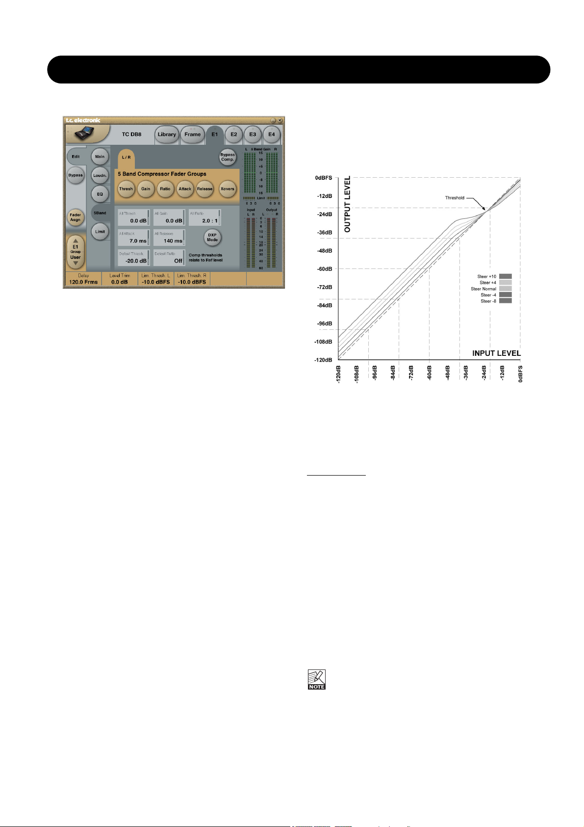
DXP Mode - introduction
The 5-band section is either in normal compression mode,
or DXP mode. Instead of attenuating signals above a
certain threshold, DXP mode (Detail Expansion) lifts up
signals below the Threshold; thereby bringing out details
rather than squashing the loud parts. DXP mode therefore
is capable of adding intelligibility and air to speech, lifting
harmonics, or emphasizing ambience without increasing
overall peak level.
As shown on the illustration, gain is positive below
threshold, unity at Threshold, and the effect decreases
above Threshold. In DXP mode, Ratio becomes Steer.
Steer can be regarded as an adaptive Ratio that gradually
approaches 1:1 above the threshold.
Multiband DXP
DXP mode can be used with any number of bands up to 5.
When used multiband it is particularly effective in bringing
out air and clarity.
The processor can act as an automatic Eq that removes a
boost when it's not needed: At very low levels, where noise
is dominant, and at loud levels where sibilance would
become a problem. Besides from being effective on
speech, DXP mode can be used in mastering to bring up
low levels, e.g. when preparing film or concerts for
domestic or noisy environment listening.
Try setting the Steer and/or Threshold parameters
differently in the bands to hear the effect. High Steer values
add more detail gain than low values, but remember that
Threshold has to be negative to add detail gain at all.
DXP Threshold relates to the Reference Level set on the
Main page.
To disable DXP detail gain at very low levels, use the
Defeat Threshold and Defeat Ratio controls. Defeat
threshold relates to the DXP threshold, and allows for
a certain level-window, inside which detail gain is
applied. Defeat Ratio determines the slope at which DXP
detail gain is defeated.
8
ATX/DTX
Ratio - DXP mode OFF
Parameter range: Off to Infinity:1
Press this button to access the five individual band Ratios
and the overall All Ratio.
The parameters are Automatically assigned to fader 1-6.
Attack
Parameter range: 0.3 to 250ms
Press this button to access the five individual band Attacks
and the overall All Attack.
The parameters are Automatically assigned to fader 1-6.
Release
Parameter range: 20ms to 7s
Press this button to access the five individual band
Release and the overall All Release.
The parameters are Automatically assigned to fader 1-6.
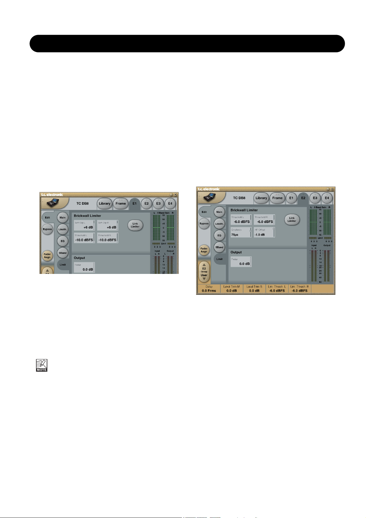
DTX Limit page
Link Limiter
Range: -3, -2, -1, Normal +1, +2, +3
When Link is active, the same amount of peak limiting is
always applied to both channels.
Some broadcasters like the sound of operating left and
right limiting without stereo coupling because they feel that
it maximizes loudness and widens the stereo image. On
dual mono sources, of course you should always choose
un-linked Limiter operation.
The Configuration control on the Main page does not
affect the Link Limiter setting. This link is running
individually from the selected configuration.
Softclip A/L and B/R
Parameter range: - 3dB to Off
When active, Soft Clip applies a saturation effect on signals
close to maximum Output level. The threshold is relative to
the Threshold of the Brickwall Limiter.
This controlled distortion of transients works well for adding
loudness, but is not a desirable effect with some data
compression codecs. While the Brickwall Limiter is
extremely low distortion, Soft Clip is not. Use your own
judgement if you want it or not.
Threshold A & Threshold B
Parameter range: -12 to 0.0dBFS
Sets the Threshold of the Brickwall Limiter.
The Threshold is relative to 0 dBFS, not to the Reference
Level set on the Main page.
The Brickwall Limiter uses 48 bit processing with distortion
figures surpassing the quality demands of DVD-Audio
mastering. Oversampling is used to prevent intersample
peaks from reaching the Output, and time-constants adapt
to the Input signal.
Fader A & Fader B
Parameter range: Off to 0dB
Fader function on the Output. When Dual Mono
configuration is selected, individual Output faders are
available.
ATX Limit page
Parameters that are not described under DTX Limit page:
Emphasis
Range: Off, 50µs, 75µs, J17
To pre-condition signal better for analog transmission, the
limiter in ATX can take downstream emphasis into account.
Note that the output signal of DB4 or DB8 does not contain
pre-emphasis, but is linear, so STL data reduction isn't
compromised. When the Emphasis parameter is set to Off,
linear limiting (like in DTX) is available.
HF Offset
Range: -12dB to 0dB
When set to 0 dB, emphasis limiting precisely follows the
selected pre-emphasis curve. However, lack of peak
conservation in the downstream signalpath (DA converters,
sample rate converters, filters, data reduction etc.) may
necessitate a more conservative HF Offset, targeting, for
instance, 1 or 2 dB below the theoretical roll-off. When the
Emphasis parameter is set to Off, HF Offset has no effect.
Output
Off, -100dB to 0dB
Output level control

9
MULTIBAND-5.1
Introduction
The Multiband-5.1 algorithm is a multi-channel, multi-band
optimizer, with Limiters and extensive possibilities to assign
channels to multiple Sidechains.
Four-band dynamics are available for 5.1-processing.
With the Multiband-5.1 it is possible to integrate dynamics
processing for 5.1 applications offering features, which are
not possible if using multiple stereo dynamic processors.
Multiband-5.1 processor contains:
• 5 channels of three band expansion and compression
• Full-range brickwall limiter on all Outputs
• 1 channel of full range expansion, compression and
limiting for the LFE (Sub) channel
• 3 Sidechains for the five main channels, that can be
assigned in flexible ways
• 1 extra Input channel that can be used for external Side
Chain Input.
Main
At the Main page you have access to the general set-up
parameters for the Expander and Compressor sections.
Meters are shown for all seven Inputs and six Outputs at
the right of the display.
Band Xover Frequencies
Lo Xover
Range: Off to16kHz
Sets the Cross-over frequency between the Lo- and the
Mid- Expander and Compressor bands for the five main
channels (LFr, RFr, Cnt, LSr, RSr).
The two Cross-over points are not allowed to cross
each other. Therefore the parameter range can be
less than 16kHz if the Hi Xover parameter is set
below 16kHz.
Hi Xover
Range: Off to16kHz
Sets the Cross-over frequency between the Mid- and the
Hi- Expander and Compressor bands for the five main
channels (LFr, RFr, Cnt, LSr, RSr).
The two cross-over points are not allowed to cross
each other. Therefore the parameter range can be
less than going down to Off, if the Lo Xover
parameter is set above the Off position.
Performance Settings
Crest
Range:
Peak, 6dB, 10dB, 12dB, 14dB, 16dB, 20dB, 24dB, RMS
Select compression method between RMS and PEAK.
The dB steps between RMS and Peak are the dBs needed
for a peak-value to override RMS measurement.
Nominal Delay
Range: 0 to 15ms
(<2ms in 0.1ms steps. >2ms in 0.5ms steps)
Sets the nominal Delay of the signal compared to the
Sidechain signal. This is also known as "Look ahead
Delay", enabling the Compressor section to become more
responsive to the incoming signal.
Automatic Make Up Gain
Range: Off/On
Switches the Automatic Make-up gain On or Off. As using
compression is a reduction of dynamic range in the signal
a compensation for this loss of gain on the Output side is
possible. Use the Auto Make Up gain to achieve this.
Reference Level
Range: -24dBFS to 0dBFS in 0.5dB steps
This parameter sets the reference level in the algorithm.
The reference level is the level at which the Threshold
parameters will start operating when set to 0dB. E.g. if the
Reference Level is set to -18dBFS (often referred to as
0dBu), a Threshold setting at -4dB, will cause the
Compressor to start operating at -22dBFS.
Algorithm Inputs/Outputs are distributed as follows:
E1 - E4
L
R
C
LFE
SL
SR
Xt
L
R
C
LFE
SL
SR
INPUT
OUTPUT
•
•
•
•
•
•
•
•
•
•
•
•
•
•
•
•
10
MULTIBAND-5.1
Side Chain - Control page
The Sidechain assignment possibilities in the Multiband-5.1
are very comprehensive. Carefully selecting which
channels should be controlled by which Sidechains, is just
as essential as dialing in the correct Threshold and Ratio
values.
It is possible to freely select any or none of three
Sidechains to control each of the main-channels. This also
gives you the option of grouping the channels. In addition
to this, the LFE channel has its own Sidechain control. This
enables e.g. setting up two Multiband-5.1 algorithms in serial
setup, while having six individual Sidechains available,
enabling fully individual Sidechain controls of all channels.
At the Feed page it is possible to make additional Sidechain
link Inputs, for e.g. having the Center-channel contributing
to the Sidechain Inputs of the two Front channels, to create
a more coherent sound from the front-channels.
The illustration above reflects the Processing parameter set
to Multiband-5.1 in Normal mode.
Basic operation
At the Setup/Control page it is possible to decide which
Sidechains should control which channels. Select any of
three Sidechains to be assigned to any of the five Mainchannels. You can also chose to pass the channels
unprocessed through the algorithm. The LFE channel can
be assigned to its own separate Sidechain, or left
unprocessed.
Setting a channel to unprocessed will preserve the
processing delay through the algorithm, keeping the
channel time-aligned to the other (processed)
channels.
Side Chain - Feed page
The Setup/SC Feed page holds parameters specifying
which Input channels should feed the three Sidechains.
Normal
Range: Off, On
When this parameter is set to “On” the Input channels
selected to be controlled by the respective sidechain will
also Input to the sidechain.
Add 1, Add 2 and Add 3
Range: Off, LFr Max, RFr Max, Cnt Max, LSr Max, RSr
Max, Xt Max, LFr Sum, RFr Sum, Cnt Sum, LSr Sum, RSr
Sum, Xt Sum.
These parameters enable extra channels to be assigned to
the respective Sidechain Input. The extra Sidechain Input
channels will not be processed by the sidechain.
The Sum settings will add the Input to the sidechain,
whereas the Max settings only will contribute to the
sidechain if the level exceeds the other Input channel
levels.
Side Chain Control
Range - for the five main channels:
• Unprocessed
• Side Chain 1
• Side Chain 2
• Side Chain 3
Range - for the LFE channel:
• Unprocessed
• LFE
11
MULTIBAND-5.1
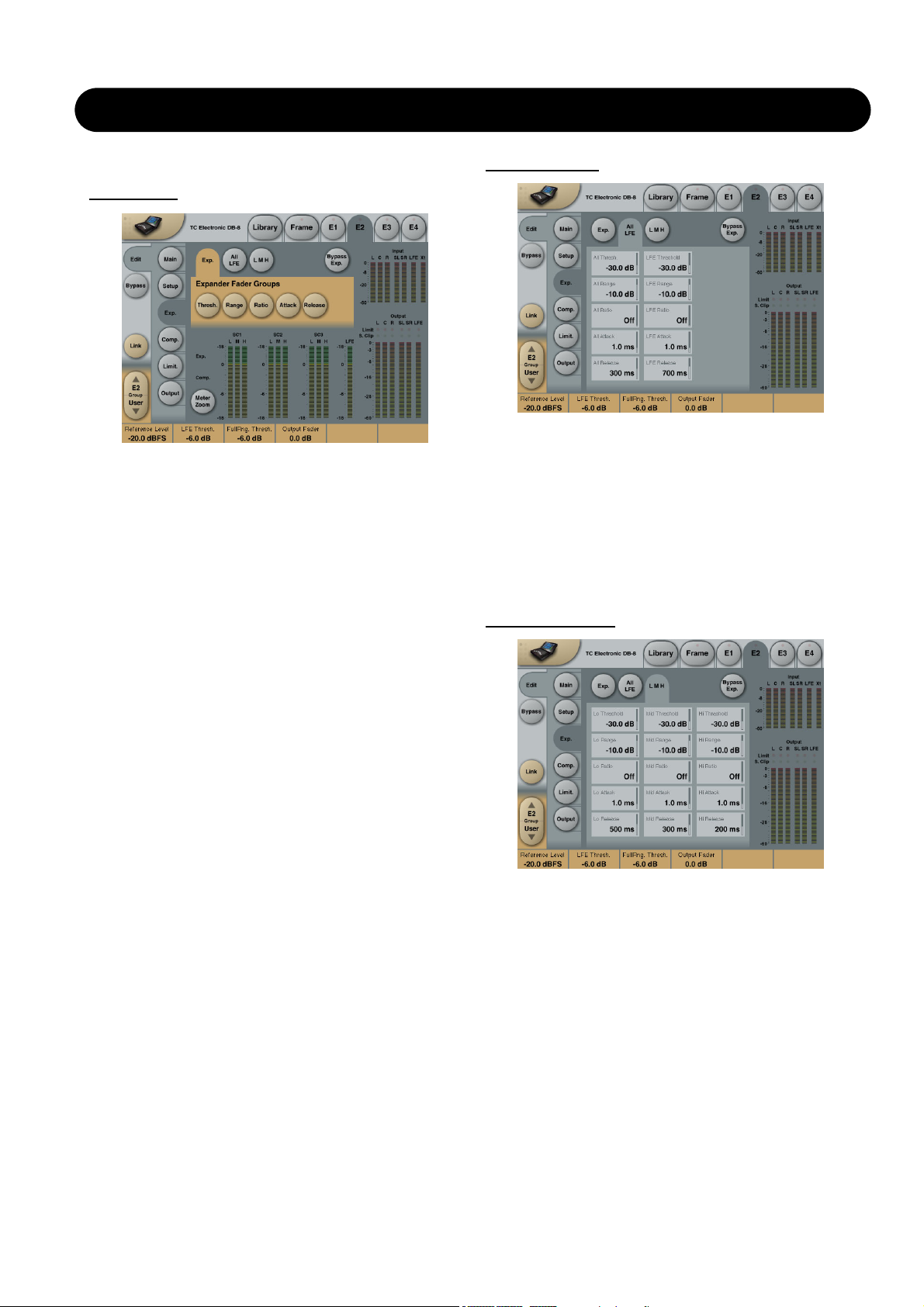
Expander
Exp. page
Pressing Threshold, Range, Ratio, Attack and Release
keys will immediately assign Lo, Mid, Hi, All and LFE
values for these parameters to Faders 1-4.
Be aware that the range of the All parameter is relative to
the settings of the same parameters in the Compressor
section.
Threshold
Range: -50dB to 0dB (in 0.5dB steps)
When the signal drops below the set Threshold point the
Expander starts to generate downward expansion.
Range
Range: -40dB to 0dB in 0.5dB steps
Sets the maximum range of the expansion.
Ratio
Range: Off to Infinity
Sets the Expansion Ratio below the Threshold point.
Release
Range: 20ms to 7sec.
Sets the time it takes for the Expander to release its
attenuation of the signal when the signal exceeds the
Threshold again.
Attack
Range: 0.3 to 100ms
Sets the time it takes for the Expander to reach the
attenuation specified by the Ratio parameter when the
signal drops below the Threshold point.
Meter Zoom
Press Zoom to decrease meter range and have a more
accurate metering.
Bypass Exp.
Press to bypass the Expander section of the MD 5.1
algorithm.
All LFE page
Pressing any parameter will assign this to Fader 6.
All - parameters
These parameters are equivalent to the “All” - Threshold,
Range, Ratio, Attack and Release parameters.
LFE - parameters
These parameters are equivalent to the “LFE” - Threshold,
Range, Ratio, Attack and Release parameters.
All L M H page
Pressing any parameter will assign this to Fader 6.
This page holds all Expander Threshold, Range, Ratio,
Attack and Release parameters for the Lo, Mid and Hi
bands.
12
MULTIBAND-5.1
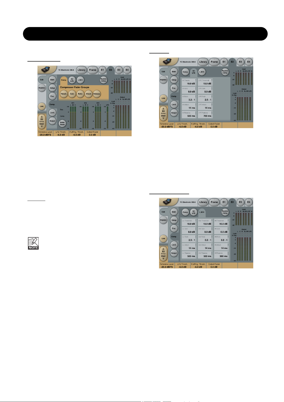
Compressor
Comp. page
Pressing Threshold, Range, Ratio, Attack and Release
keys will immediately assign Lo, Mid, Hi, All and LFE
values for these parameters to Faders 1-4. Be aware that
the range of the All parameter is relative to the settings of
the same parameters in the Expander section.
Threshold
Range: -25dB to 20dB (in 0.5dB steps)
Sets the Threshold level at which the Compressor starts to
operate. The Threshold parameter relates to the Reference
Level setting.
Example:
If the Reference Level is set to -18dBFS, a
Threshold setting of -4dB, will cause the compressor to
start operating at -22dBFS.
Gain
Range: Off, -18dB to 12dB in 0.5dB steps.
Adjusts the gain after the Compressor.
If the Auto Make-up gain parameter is set to On in
the Main page, these gains will already have been
adjusted according to the Threshold and Ratio
parameters.
Ratio
Range: Off to Infinity
Sets the Compression Ratio that must be performed above
the Threshold point.
Attack parameters
Range: 0.3 to 100ms
Sets the time the Compressor takes to reach the
attenuation specified by the Ratio parameter when the level
exceeds the Threshold point.
Release parameters
Range: 20ms to 7sec.
Sets the time the Compressor takes to release the
attenuation of the signal when the signal level drops below
the Threshold point.
Meter Zoom
Press Meter Zoom to decrease meter range and have a
more accurate metering.
All LFE
Pressing any parameter will assign this to Fader 6.
All - parameters
These parameters are equivalent to the “All” - Threshold,
Range, Ratio, Attack and Release parameters.
LFE - parameters
These parameters are equivalent to the “LFE” - Threshold,
Range, Ratio, Attack and Release parameters.
All L M H page
Pressing any parameter will assign this to Fader 6.
This page holds all Compressor Threshold, Range, Ratio,
Attack and Release parameters for the Lo, Mid and Hi
bands.

13
MULTIBAND-5.1
Limiter
The Limiter page is divided into three Sub-pages. One
covering the Softclip section, one for the Full Range Limiter
and one for the LFE Limiter.
Generic p
arameters in this algorithm:
Meter Zoom
Press Meter Zoom to decrease meter range and have a
more accurate metering.
Bypass Limiter
Press to Bypass the Limiter section of the 5.1 algorithm.
Soft Clip page
Softclip
Full Range Softclip
Range: -6dB to Off
Softclipper Threshold setting after the Compressor for the
five multiband channels. Threshold is always relative to
0dBFS (Not the Reference Level.
LFE Softclip
Range: -6dB to Off
Softclipper Threshold setting for the LFE channel only.
Full Limit. p
age
Threshold
Range: -12dB to Off
-6 to OdB in 0.1dB increments
-12 to -6 in 0.5dB increments
Brickwall limiter for the five multiband channels. Threshold
is always relative to 0dBFS. LED on each Output meter
indicates when Limiter is active.
Release
Range: 0.01 to 1.00 seconds
Release time for the Limiter.
Ceiling
Range: -0.10dB to 0dB
Fine-tuning parameter setting the Ceiling for the Limiter.
The Ceiling parameter prevents the Output signal
from exceeding the adjusted Limiter Threshold. It
can be used to "hide" overloads to downstream
equipment, but it does not remove the distortion
associated with an over.
LFE Limiter page
LFE Limiter
Threshold
Range: -12 to +3dB
-6 to + 3 in 0.1dB increments
-12 to -6 in 0.5dB increments
Brickwall limiter for the LFE channel. Threshold is always
relative to 0dBFS. LED on each Output meter indicates
when limiter is active.
Release
Range: 0.01 to 1.00 seconds
Release time for the Limiter.
Ceiling
Range: 0 to -0.10dB in 0.01dB steps.
Fine-tuning parameter setting the Ceiling for the Limiter.
The Ceiling parameter prevents the Output signal
from exceeding the adjusted Limiter Threshold. It
can be used to "hide" overloads to downstream
equipment, but it does not remove the distortion
associated with an over.
14
MULTIBAND-5.1
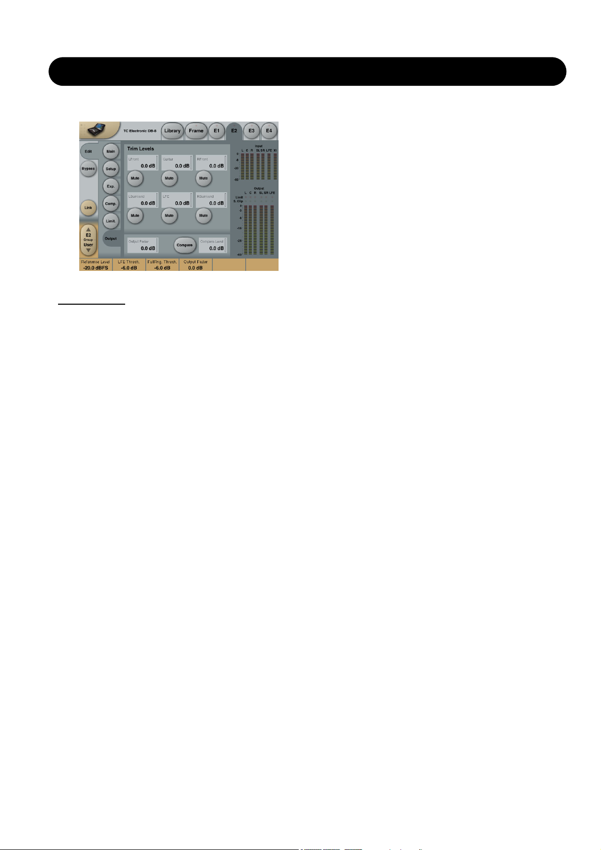
Output
Trim Levels
Output trims
Range: 0dB to -12dB in 0.1dB steps
Level trim of the Output channels. Only the fader is placed
after these trims. These parameters can be used to trim the
levels of the monitoring system, but please note that it also
affects the recorded material.
Mute
Allows muting of each Output-channel.
Output Fader
Range: Off to 0dB
(<-40dB: in 3dB steps, >-40 in 0.5dB steps)
Output fader for all 6 Outputs. Can be controlled with the
optional TC Master Fader connected to the GPI Input.
Compare
Easy switchable On/Off compare function for the entire MD
5.1 algorithm. This is not a bypass function as you are able
to set a Compare Level (see below).
Compare Level
Range: -20 to 0dB
This function allows you to set a Compare level of the
processed signal to match the unprocessed signal for
better A/B listening.
15
MDX 5.1
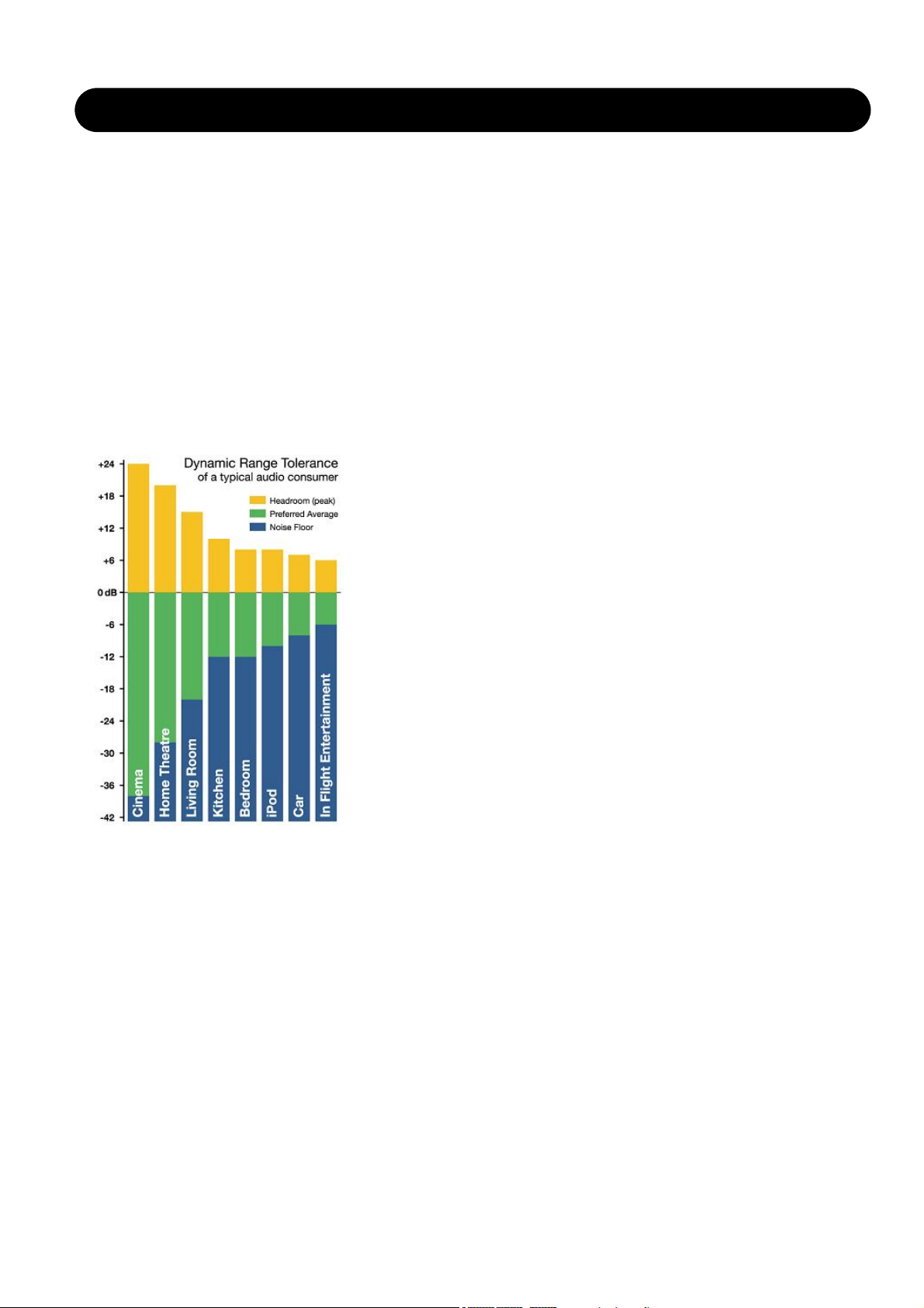
Fig 1. DRT map for consumers under different listening situations.
Dynamic Range of Broadcast Material
Today, program material for TV broadcast is generally aimed at a listener in the Living Room or Kitchen region, see Fig 1.
This kind of material should be thought of as having a normal broadcast dynamic range signature.
Commercials, promos and consumer CDs typically have a more restricted dynamic range, and therefore appear loud on
TV, where normalization is based only on peak content. This kind of material should be thought of as having a hot dynamic
range signature.
On the opposite side we have film production, aimed at a completely different listening scenario, where much softer and
much louder level than the average can be reproduced and heard. Production for wide dynamic range listening can also
include classical or acoustic music. All material of such nature should be thought of as having a soft dynamic range
signature.
Music and entertainment radio is typically aimed at Car listening, so the dynamic range signature is generally hot. The only
type of radio with a wider dynamic range typically carries classical music, drama and low key, talk based programming.
To summarize, broadcast material is produced in a way that fits the listening conditions of a wide majority of consumers in
the best possible way. The most dramatic difference between program material and consumer requirements concerns
feature film. To have a feature film align with domestic listening conditions without loosing too much detail, or distorting the
loud parts, low level may need to be brought up by 12-20 dB, and the headroom restricted by 12-16 dB.
Introduction
MDX5.1 is a high resolution dynamic range processor for multichannel signals. It may also be used to process for mono or
stereo, thereby making changes or adjustments unnecessary.
Its combination of low level lift, multi-band structure, output limiting and extensive controls offers the most sophisticated
dynamic range translation capabilities in the professional audio industry today. Not surprisingly, MDX5.1 has become the
standard for dynamic range control in film and music mastering.
Dynamic Range Tolerance, DRT, at the consumer
The Dynamic Range Tolerance map, Fig 1, illustrates the dynamic range targets for various listening environments. It is
therefore a practical tool for optimizing listener pleasure in digital broadcast.
According to recent studies, listeners typically object against too wide dynamic range much more than when the range is
too restricted. Lack of speech intelligibility is the second worst offender, and often the cause for requesting more dynamic
range limitation. Against the hopes of audio aficionados, as more people are listening through headphones (iPods and
other personal entertainment systems), the DRT trend is therefore currently moving towards more dynamic range
restriction in broadcast.

16
MDX 5.1
Processing for Digital Broadcast
Digital broadcast has the potential to carry more formats at a wider dynamic range than analog. For example, feature films
can be presented more like they were mixed and edited, with fewer compromises on the picture as well as on the audio
side. However, even for HDTV, audio still needs optimization for a presentation environment different than a cinema, like
the picture still needs color space, rate and resolution corrections.
The jumping level problem from analog TV will become bigger if stations transmit feature films with a less suitable dynamic
range than today, because film fall way outside the Dynamic Range Tolerance of the average consumer under her
domestic listening conditions.
Consequently, dynamic range restriction must take place either at the station, or inside the consumer's receiving device.
Dynamic range translation should deal with both overly soft and overly loud parts. Ideally, the perfect re-mapping should
happen at the receiving end to accommodate a wide range of listening conditions. Metadata in conjunction with, for
instance, Dolby AC3, provides some of these capabilities. However, even if the consumer knows how to adjust the dynamic
range of a film to her current listening conditions, the optimum dynamics treatment unfortunately far exceeds the
capabilities of an AC3 decoder. The dynamic range control in the codec is acceptable for cut and boost ranges of 4-6 dB,
but preparing a feature film for broadcast needs considerably more than this.
If such a large correction is left only to the AC3 decoder, the wide-band gain changes can be quite audible. Film and music
dynamic range correction requires a multiband structure so listeners don't sacrifice speech intelligibility, or get subjected to
the spectral intermodulation of a crude, wideband range controller.
MDX5.1
The MDX5.1 processor available in DB4 and DB8 is capable of bringing up low level detail, rather than boosting
everything, and then having to limit the transients afterwards, see Fig 2. Low level lift can even be applied to specific
channels selectively in one, two or three frequency bands.
Fig 2. DXP processing vs. traditional Compression and Limiting.
Note how already loud signals are unnecessarily affected when relying on limiting and clipping.

17
MDX 5.1
Applications
MDX5.1 is well suited for dynamic range control of any kind of broadcast material. Film, sports, music or game shows. It
may be applied during ingest, transmission - or both places.
With suitable parameter settings, high resolution audio can pass through more than one hundred MDX5.1 processors
without perceivable degradation of quality The ingenious topology of DB4 and DB8 allows for the processing to be
performed instantly (the latency is below 0.5 ms, equivalent to moving a microphone approximately 16 cm or 6 inches),
making re-alignment of audio and picture a non-issue.
Processing strategies
The major part of dynamic range translation should be done at the station, leaving only smaller corrections to be performed
at the consumer. This ensures competitive audio with regards to consistency, quality and speech intelligibility, and prevents
asking more from the AC3 decoder than it can deliver in a civilized manner.
Fig 3. Example of dynamic range re-mapping: From Home Theatre/DVD to Living Room listening conditions (Fig 1).
Fig 3 and Fig 4 show rational transfer characteristics complying with the DRT of the consumer, without affecting levels
when they are already on target.
Fig 4. Example of dynamic range re-mapping: From Home Theatre/DVD to Living Room listening conditions (Fig 1).
18
MDX 5.1
Basic Operation
On the Main page, MDX5.1 offer Input Gain controls for the Main Channels and for the LFE Channel. This enables positive
and negative gain normalization to be performed in the 48 bit domain prior to low level processing and output limiting.
These gain controls therefore operate in a safe location, well protected from generating output overloads.
Tip: Use the Input Gains as overload protected level trims in a critical realtime system, such as broadcast, OB or live
music.
On the Link pages, the 5 Main channels (L, C, R, SL and SR) can be linked in numerous ways. The concept is to assign a
channel to a Sidechain. If all channels are assigned to the same Sidechain, processing is identical on all of them. If a
channel is assigned to a different Sidechain, processing on that channel may be different from processing on the other
channels.
The DXP pages reveal separate controls for Sidechain 1-3 plus LFE. This enables, for instance, different settings for the
Center or Surround channels, where speech intelligibility or low level ambience tend to get lost. Like when a feature film is
re-purposed for broadcast or DVD under domestic listening conditions.
If it is required to process more audio channels than 5.1, Engines can be run in parallel to cater for 6.1, 7.1, 10.2, 12.2 or
even higher number formats. Parallel Engines attain perfect phase conservation and resolution, and do not compromise
audio in any way.
MDX5.1 features 48 bit fixed point processing throughout. Split and reconstruction filters are phase linear when the
algorithm is used in multiband modes.
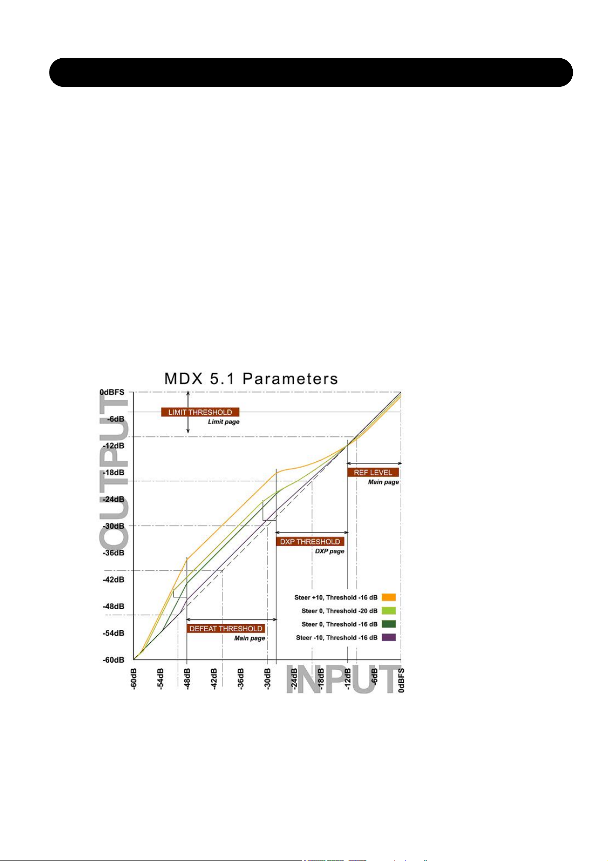
Fig 5. MDX5.1 Level Diagram for different Steer and Threshold settings..
Defeat Threshold relates to DXP Threshold which relates to Ref Level.
Limit Threshold only relates to Digital Full Scale output level.

19
MDX 5.1
The Ref Level parameter on the Main page sets the unity gain point for all channels (unless gain offsets are applied), see
Fig 5. The Thresholds on the DXP pages are relative to Ref Level, so in this particular drawing, Ref Level is set at -12
dBFS, while most DXP Thresholds are set at -16 dB. If you invoke the Defeat Threshold, gain reverts to unity for "below
radar" input levels. Defeat Threshold is relative to DXP Threshold. In the drawing, the Defeat Threshold is set at -20 dB.
Note, that the lower the DXP Threshold, or the higher a Steer setting, the more low level boost is applied. The low level
boost can be different in different channels, and even in different frequency bands.
Also observe that the Limiter threshold setting is not relative to Ref Level, but always referenced to output full scale.
Reading the Gain Meters
Gain meters in indicate absolute gain. The upper segments of a meter gives an indication of the boost and frequency
response applied to low level signals, while the lower segments of a meter gives an indication of the current (dynamic) gain
and frequency response, see Fig 6.
In this example, low level signals are subject to a 5 dB boost in the Low and Hi band. The Low frequency band is currently
attenuated by 2 dB, while the Mid and Hi bands are at 0 dB gain.
Fig 6. Example of MDX5.1
Gain Meter.The meter shows max low level gain
and spectral response, plus current gain and spectral
response.In the example, the Low band is currently
attenuated by 2 dB, while Mid and Hi bands are at
unity gain (0 dB).
Adjustment Tips
The easiest way to specify the yellow area of Fig 1 is to set an appropriate difference between the Ref Level parameter
and the Limit Threshold.
Wide dynamic range material for a high resolution delivery might be broadcast with a substantial difference between the
two, for instance 15 dB or more.
If the audio bandwidth is low, and the listener environment presumably noisy, the difference between Reference and Limit
Thresholds should smaller. For heavily data reduced multi-channel broadcast, best results are typically obtained with a 610 dB difference.
When significant data reduction is to be used, also be careful not to allow peaks going all the way to 0 dBFS. Consider
bringing down the Limit Threshold between 1 and 4 dB. Judge the quality of loud, spacious material passing through
MDX5.1 plus data reduction plus decoding, while listening to the output of the data reduction decoder. Pay special
attention to transient distortion, and if the sound image collapses at high levels.
In general, and especially for feature film re-mapping in ingest, start by processing all channels by the same amount. This
can be achieved by assigning all channels to Sidechain 1, or by using different sidechains with identical settings. Then
conclude if speech in the center channel, ambience in the surrounds or activity in the LFE channel etc. needs special
attention and processing.
When it is indicated to bring up dialog level and speech intelligibility, you may end up with something like the level diagram
presented in Fig 5. This particular transfer curve has been used successfully at stations with special attention to speech
intelligibility.
Compare against the DRT chart, fig 1, and note how the Center channel is given an extra low level advantage compared to
the four lateral channels, without the basic mix balance being generally changed. This curve ensures that dialog can still be
heard when the words could otherwise be lost to listening room noise. The lateral channels are linked two and two, or all in
one group. Presets of this nature is located in Engine Factory Bank F2 ("Loudness, Multichannel"), decade 3, preset 0-3
("Film Curve C3 - C12").

20
MDX 5.1
Fig 7. Example of multiband dynamic range re-mapping of a 5.1 feature film to domestic listening conditions. Preset
names: "Film Curve C3-C12".
Black curve: Center channel. Orange curve: L, R, Ls, Rs.
Tip: To produce multiple ingest versions from the same source material, start doing the one for the highest resolution.
Lower resolution versions can be achieved by adjusting the Limit Threshold to comply with the alternative delivery format,
then adjusting the Ref Level to optimize results under the new, restricted dynamic range conditions. In many cases, no
further tweaking will be needed.
Please be advised that some reproduction systems distort when downmixing hot multichannel signals to stereo. Therefore,
don't abuse multichannel formats by bringing all channels close to 0 dBFS at the same time, except for short duration, loud
incidents.
Tip: When making the final transmission adjustments, try changing the Ref Level parameter up and down a few dB. This is
an efficient way of trimming hundreds of parameters in MDX5.1 at the same time. Listen to the result, while deciding what
is the optimum setting for that particular broadcast platform.
MDX5.1 Factory Preset Nomenclature
Engine presets based on the MDX5.1 algorithm is located in Factory Bank F2 ("Loudness, Multichannel"), decade 2 and 3.
Presets are labelled Film Curve A-D plus a number.
Film Curve A presets add the same amount of boost to all 5.1 channels. At Reference Level, the gain is unity (0 dB). At low
level (- 35 dBFS and below), the number after the "A" in the preset title indicates the amount of low level boost. For
example, the preset "Film Curve A6" adds 6 dB of low level gain to all 5.1 channels.
Film Curve C presets add the same amount of boost to all 5.1 channels, but the max gain is achieved earlier for the Center
channel than for the rest (like in Fig 5). At Reference Level, the gain is unity (0 dB). At low level (- 35 dBFS and below), the
number after the "C" in the preset title indicates the amount of low level boost. For example, the preset "Film Curve C6"
adds 6 dB of low level gain to all 5.1 channels.
Film Curve D presets add 3 dB more gain to the Center channel than to the other channels. Max gain is also achieved
earlier for the Center channel than for the rest (like in Fig 5). At Reference Level, the gain is +3 dB for the Center channel,
but unity (0 dB) for the others. At low level (- 35 dBFS and below), the number after the "D" in the preset title indicates the
amount of low level boost. For example, the preset "Film Curve D6" adds 9 dB of low level gain to the Center channel, but
6 dB of low level gain to the rest of the channels.

21
MDX 5.1 PAGES
Main page
Input Gain Normalizer for
Main and LFE channels
Range: -18dB to +18dB
As we process in a 48 bit domain both positive and
negative gain normalization can be performed prior to low
level processing and output limiting. These gain controls
therefore operate in a safe location, well protected from
generating output overloads.
Reference Level
Range: -24dBFS to 0dBFS in 0.5dB steps
This parameter sets the reference level in the algorithm.
The reference level is the level at which the Threshold
parameters will start operating when set to 0dB. E.g. if the
Reference Level is set to -18dBFS (often referred to as
0dBu), a Threshold setting at -4dB, will cause the
Compressor to start operating at -22dBFS.
Crest
Range: Peak, 6dB, 10dB, 12dB, 14dB, 16dB, 20dB, 24dB, RMS
Select compression method between RMS and PEAK.
The dB steps between RMS and Peak are the dBs needed
for a peak-value to override RMS measurement.
DXP Defeat Level
Range: Off, -30dB to -3dB
MDX5.1 may remove low level gain below the threshold set
with this parameter to avoid having irrelevant sources (e.g.
background noise) become audible. Low level gain is not
revoked if the DXP Defeat Level parameter is set to Off.
The Defeat threshold is relative to DXP Band Thresholds,
which are relative to Reference Level.
Example: If Reference Level is set at -20 dBFS, Band
Thresholds at -15 dB, and DXP Defeat at -22 dB, low level
boost starts rolling off at -47 dBFS. See example at page 18.
Nominal Delay
Range: 0 to 15ms
(<2ms in 0.1ms steps. >2ms in 0.5ms steps)
Adds a delay to the passing audio in order to have regula-
Link Control page
The Sidechain assignment possibilities in the MDX5.1 are
very comprehensive. Carefully selecting which channels
should be controlled by which Sidechains, is just as
essential as dialing in the correct Threshold and Ratio
values.
It is possible to freely select any or none of three
Sidechains to control each of the main-channels. This also
gives you the option of grouping the channels. In addition
to this, the LFE channel has its own Sidechain control. This
enables e.g. setting up two Multiband-5.1 algorithms in serial
setup, while having six individual Sidechains available,
enabling fully individual Sidechain controls of all channels.
At the Feed page it is possible to make additional Sidechain
link Inputs, for e.g. having the Center-channel contributing
to the Sidechain Inputs of the two Front channels, to create
a more coherent sound from the front-channels.
tion start "ahead of time". Using this control can reduce the
need for peak limiting, and prevent dynamic distortion from
being added to sensitive material.
Note that look-ahead is scaled with Attack per band.
Example: If a 5 ms Nominal Delay has been set, and
Attack is 10 ms on the low band and 1 ms on the high
band, audio is delayed 5 ms on all bands (phase linear
topology). However, to prevent pre-transient holes from
being generated, Attack regulation starts 5 ms "ahead of
time" on the low band, but only a little more than 1 ms
"ahead of time" on the high band.
Hi/Lo Crossovers
MDX5.1 uses a phase linear, 48 bit split and recombination filter structure in order to enable different low
level detail boost at different frequencies. This counteracts
spectral inter-modulation, and is useful in order to preserve
speech intelligibility. Two-band or wide-band DXP
processing can be accomplished by setting one or both
crossover points to Off.

22
MDX 5.1 PAGES
The illustration above reflects the Processing parameter set
to MDX5.1 in Normal mode.
Basic operation
At the Setup/Control page it is possible to decide which
Sidechains should control which channels. Select any of
three Sidechains to be assigned to any of the five Mainchannels. You can also chose to pass the channels
unprocessed through the algorithm. The LFE channel can
be assigned to its own separate Sidechain, or be left
unprocessed.
Setting a channel to unprocessed will preserve the
processing delay through the algorithm, keeping the
channel time-aligned to the other (processed)
channels.
Sidechain Control
Range - for the five main channels:
• Unprocessed
• Side Chain 1
• Side Chain 2
• Side Chain 3
Range - for the LFE channel:
• Unprocessed
• LFE
Link Feed page
The Setup/SC Feed page holds parameters specifying
which Input channels should feed the three Sidechains.
Normal
Range: Off, On
When this parameter is set to “On” the Input channels
selected to be controlled by the respective sidechain will
also input to the sidechain.
DXP page
Sidechain Fader Groups
The DXP pages reveal separate controls for Sidechain 1-3
plus LFE. This allows for different settings for the Center or
Surround channels, where speech intelligibility or low level
ambience tend to get lost, like when a feature film is repurposed for broadcast or DVD under domestic listening
conditions.
If it is required to process more audio channels than 5.1,
Engines can be run in parallel to cater for 6.1, 7.1, 10.2,
12.2 or even higher number formats. Parallel Engines
attain perfect phase conservation and resolution, and do
not compromise audio in any way.
Add 1, Add 2 and Add 3
Range: Off, LFr Max, RFr Max, Cnt Max, LSr Max, RSr
Max, Xt Max, LFr Sum, RFr Sum, Cnt Sum, LSr Sum, RSr
Sum, Xt Sum.
These parameters enable extra channels to be assigned to
the respective Sidechain Input. The extra sidechain Input
channels will not be processed by the sidechain.
The Sum settings will add the Input to the sidechain,
whereas the Max settings only will contribute to the
sidechain if the level exceeds the other Input channel
levels.

23
MDX 5.1 PAGES
Limit page - Soft Clip
The Limiter page is divided into three Sub-pages. One
covering the Softclip section, one Main Limiter and one for
the LFE Limiter.
Generic p
arameters in this algorithm:
Meter Zoom
Press Meter Zoom to decrease meter range and have a
more accurate metering.
Bypass Limiter
Press to Bypass the Limiter section.
Softclip
Full Range Softclip
Range: -6dB to Off
Softclipper Threshold setting after the Compressor for the
five multiband channels. Threshold is always relative to
0dBFS (Not the Reference Level.
LFE Softclip
Range: -6dB to Off
Softclipper Threshold setting for the LFE channel only.
Limit page - Main
Threshold
Range: -12dB to Off
-6 to OdB in 0.1dB increments
-12 to -6 in 0.5dB increments
Brickwall limiter for the five channels. Threshold is always
relative to 0dBFS. LED on each Output meter indicates
when Limiter is active.
Release
Range: 0.01 to 1.00 seconds
Release time for the Limiter.
Ceiling
Range: -0.10dB to 0dB
Fine-tuning parameter setting the Ceiling for the Limiter.
The Ceiling parameter prevents the Output signal
from exceeding the adjusted Limiter Threshold. It
can be used to "hide" overloads to downstream
equipment, but it does not remove the distortion
associated with an over.
LFE Limiter
Threshold
Range: -12 to +3dB
-6 to + 3 in 0.1dB increments
-12 to -6 in 0.5dB increments
Brickwall limiter for the LFE channel. Threshold is always
relative to 0dBFS. LED on each Output meter indicates
when the Limiter is active.
Release
Range: 0.01 to 1.00 seconds
Release time for the Limiter.
Ceiling
Range: 0 to -0.10dB in 0.01dB steps.
Fine-tuning parameter setting the Ceiling for the Limiter.
The Ceiling parameter prevents the Output signal
from exceeding the adjusted Limiter Threshold. It
can be used to "hide" overloads to downstream
equipment, but it does not remove the distortion
associated with an over.

24
MDX 5.1 PAGES
Output page
Trim Levels
Output trims
Range: 0dB to -12dB in 0.1dB steps
Level trim of the Output channels. Only the fader is placed
after these trims. These parameters can be used to trim the
levels of the monitoring system, but please note that it also
affects the recorded material.
Mute
Allows muting of each Output-channel.
Output Fader
Range: Off to 0dB
(<-40dB: in 3dB steps, >-40 in 0.5dB steps)
Output fader for all 6 Outputs. Can be controlled with the
optional TC Master Fader connected to the GPI Input.
Compare
Easy switchable On/Off compare function for the entire MD
5.1 algorithm. This is not a bypass function as you are able
to set a Compare Level (see below).
Compare Level
Range: -20 to 0dB
This function allows you to set a Compare level of the
processed signal to match the unprocessed signal for
better A/B listening.

25
DOWNCONVERT 5.1
Main page
Fader 5.1
Parameter range: Off, -120 to 0dB
For the 5.1 I/O channels (L, C, R, SL, SR and LFE), this
fader performs Output level control.
Delay 5.1
Parameter range: 0 to 1200ms
For the 5.1 I/O channels (L, C, R, SL, SR and LFE), this
parameter Delays all channels simultaneously. The Delay
can be changed seamlessly on the fly.
The individual Sample Delay parameters at the Trim
page are additional delay to the setting of this
parameter.
Mute 5.1
Parameter range: On/Off
Toggle this switch to Mute all 5.1 output channels.
Fader ch. 7-8
Parameter range: Off, -120 to 0dB
For the I/O channels 7 and 8, this fader performs Output
level control.
Delay ch. 7-8
Parameter range: 0 to 1200ms
For I/O channels 7 and 8, this parameter Delays the
channels simultaneously. The Delay can be changed
seamlessly on the fly.
The individual Sample Delay parameters at the Trim
page are additional delay to the setting of this
parameter.
Mute ch. 7-8
Toggle this switch to Mute the Output of channels 7 and 8.
Parameter range: On/Off
Format page
The format conversion block enables you to down-mix 5.1
signals to LCRS, Stereo or Mono mix's including Limiter
function.
Level Trim
Delay
Solo/Mute
Phase Inv.
Bass
Management
Calibration
noise-tone
Level Trim
Solo/Mute
Format
Conversion
Limiting
Input Output
Introduction
DownConvert-5.1 is an algorithm offering mix-down functionality of different multi-channel formats to LCRS, Stereo or
Mono mixes. LFE(Sub) channels can also be Extracted or Distributed to and from the 5.1 main Input channels (Bassmanagement). Also 5.1 calibration tools with different noise and sine outputs are available. On top of the 5.1 capabilities,
DownConvert-5.1 contains two thru channels at I/O 7 and 8, with adjustable level and delay.
Algorithm Inputs/Outputs are distributed as follows:
E1 - E4
L
R
C
LFE
SL
SR
7
8
L
R
C
LFE
SL
SR
7
8
INPUT
OUTPUT
•
•
•
•
•
•
•
•
•
•
•
•
•
•
•
•

26
DOWNCONVERT 5.1
Output Format
The Output Format section is basically used to convert
Multi-channel signals to other formats. E.g. when going
from a 5.0 mix to a Stereo or mono signal.
Note that the Bass management is placed before this
format conversion in the signal chain. Use the distribute
part of the Bass-Management to convert from 5.1 to 5.0
mix.
Output Format
Range: 5.1 (=Off or Thru), LCRS, Stereo or Mono
Selects the Output format in which your five main channels
Input material will be mixed down to.
90º Mono
90 degrees mono Insert. This option is placed just before
the two Limiters, meaning at LFr + RFr when Output format
is set to Mono, and LSr + RSr channels when LCRS is
selected as Output format.
Mono Output
Range: Center, LFr+RFr
Selects the Output channel when Mono is selected as
Output format.
Mix Levels
From L/R
Range: -100dB to 0dB
Sets the Input level from the Left and Right front channels.
This parameter is only available when Output is set
to Mono or Stereo.
From Center
Range: -100dB to 0dB
Sets the Input level from the Center channel.
This parameter is only available when Output is set
to Mono or Stereo.
From SL/SR
Range: -100dB to 0dB
Sets the Input level from the Left and Right surround
channels.
Limiter
Two channels of broadband Output brickwall limiter, that
are placed differently according to the selected Output
format.
Output format: 5.1 Thru
The Limiter is inactive.
Output format: LCRS
The Limiter operates on the LS and SR channels.
Output format: Stereo
The Limiter operates as a Stereo Limiter on Left and Right
front channels.
Output format: Mono
The Limiter operates on the Mono sum Output.
Threshold
Range: -12 to 0dB
Limiter Threshold level for the two limiters available. The
Limiters will be placed at LFr + RFr Outputs when Stereo
or Mono mode is selected as Output formats, and at LSr +
RSr when LCRS is selected as Output format.
Release
Range: 10 to 1000 ms
Sets the Release time for the selected Limiter.
Bass management page
Bass Management
Range: Extract, Distribute, Inactive
When the LFE Mode parameter is set to Distribute, the
Bass Management enables you to add LFE information to
the six Output channels in the system. This can normally
be compared to a 5.1 -> 5.0 process, but it can also be a
5.1 -> 5.1 process, leaving the LFE channel unprocessed,
while adding LFE information to the five Main-channels.
The Bass Management is placed just before the Output
Format conversion.
Main Channels
Lo Cut
Range: 10 - 200Hz
Sets the frequency for the Lo Cut filter, on the five main
Output channels (LFr, RFr, Cen, LSr, RSr)
Order
Range: Off, 2nd, 4th order
Sets the slope of the Main channels Lo Cut filter.
LFE Channel
Hi Cut
Range: 10 - 200Hz
Sets the frequency for the Hi Cut filter on the LFE channel.

27
DOWNCONVERT 5.1
Order
Range: Off, 2nd, 4th order
Sets the slope of the LFE Hi Cut filter.
Main Channels To LFE/
LFE To Main Channels
Depending on the selected Bass Management Mode,
Distribute or Extract, the Last section on the Bass page will
appear as: “Main Channels to LFE” or “LFE to Main
Channels”.
Via the parameters: L Front, Center, R Front, L Surround,
LFE and R Surround, - it is possible to either:
• feed the main channels with signal from the LFE channel.
• feed the LFE channel with signal from the Main Channels.
L Front, Center, R Front,L Surround, LFE, R Surround
Range: -100 - 0dBFS
-100 -> -40dB in 3dB steps,
-40 -> 0dB in 0.5dB steps
Main Channels
To LFE - Extract mode
In this mode the Level controls are used to extract signal
from the Main Channels and feed them to the LFE channel.
Use this mode when converting a 5.0 format to 5.1.
LFE To Main Channels - Distribute mode
In this mode the Level controls are used to distribute the
LFE signal to the five Main Channels.
Use this mode when converting a 5.1 format to 5.0.
Solo page
Solo buttons
This page contains individual Solo buttons for all Inputs
and Outputs. Several channels can be soloed
simultaneously.
Trim page
General operation
The tabs in the top of the page (Front, Center, Surr, LFE,
Ch.7/8) is used to select parameters for the respective I/O
channels. Following parameters are available for each I/O
channel:
Input Level
For each of the eight Inputs, separate Input level controls
are available.
Parameter range: Off, -120 to 0dB
Output Level
For each of the eight Outputs, separate Output level
controls are available.
Parameter range: Off, -120 to 0dB
Phase Invert
For each of the eight Inputs, the ability to phase-invert the
signal 180-degrees is available
Parameter range: On, Off
Delay in samples
For each of the eight channels, fine-adjustable Delay
measured in samples can be added.
The Sample Delay is additional to the delay parameter in
milliseconds.
The corresponding value in milliseconds depends
whether the DB8/DB4 is running at 44.1 or 48kHz
sample rate. E.g. 48 samples is equal to 1ms at
48kHz and 1.088ms at 44.1kHz.

28
DOWNCONVERT 5.1
Calibration page
Test signal generator (Oscillator)
Downconvert-5.1 integrates a comprehensive test-signal
generator meant for aligning the monitor system.
When a Test signal is selected, the Input source will
not be present on the Outputs.
The Calibration tone is delivered on the very Input
of the Downconvert.
Generator
Type
Range: Sine, PinkNoise
WhiteNoise
LPF Pink Noise (Low Pass Filtered Pink noise),
HPF Pink Noise (Hi Pass filtered pink noise)
This parameter selects the Signal generator type.
Default: Sine
Sine Frequency
Range: 20Hz to 20kHz
Selects the frequency when Osc. Type is set to Sine.
Default: 1kHz
Output Level
Output Level (RMS)
Range: -60 - 0dBFS
-60 -> -6dB in 1dB steps
-6 -> 0dB in 0.1dB steps
Sets the level of the selected generator to all six Output
channels.
Default: -20dBFS
LFE Trim
Range: -12 - 0dB, in 0.1dB steps
Attenuates the LFE Output channel relative to the main
test-generator level.
Thru - Thru channels are “hardwired” without any
adjustment options.

29
UPCONVERT-5.1 (UNWRAP)
Introduction
Upconvert-5.1 in use
Upconvert-5.1 measures phase, delay and spectral
differences between a pair of stereo channels to create a
5.1 result. For different program material there will be
different optimum settings that best represent the qualities
put into the original mix.
Please familiarise yourself with the controls and parameterranges on known material before you attempt
upconvert-5.1ping new stuff.
Setting up
We suggest that you try Upconvert-5.1 with the Output
being monitored through the Downconvert 5.1 (e.g. by
loading preset "5.1 Monitor Matrix"). This way you can
collapse the 5.1 signal to stereo or mono, and make sure
the result is still list enable.
Try loading some of the Upconvert-5.1 presets. You can
A/B the process by pressing Bypass on the Upconvert-5.1
Engine, or collapse the signal to stereo again by selecting
Stereo format on the Downconvert Engine, if it is inserted
downstream as suggested above.
Time alignment
When all Delays are set at "0", all Outputs from Upconvert-
5.1 are aligned with sample precision. The basic Delay
through the algorithm in this case is 3.6 ms at 44.1 and
48kHz. Try offsetting the Delays in samples and ms, and
note the shift in image.
Delays may be used...
- on the Surround channels to ensure that sounds appear
to originate from the front speakers.
- on the Center channel to compensate for its position.
- on the LFE channel to compensate for speaker position
or to advance/delay it for artistic reasons.
When the front channels are not assigned the same Delay,
please note that a subsequent stereo down-mix may not
work so well.
Bit Transparency
When 0% L/R Processing is selected, Input Trims and
Output Levels are at 0dB, the Inputs are bit transparently
cloned to the L Front and R Front Outputs.
Main Page
Input trims are provided to carefully match the L/R balance.
If working from analog tape, adjust balance with a 1kHz
calibration tone. If working from a digital master with stereo
levels at full scale, it may be necessary to adjust down
Input levels a little bit to avoid Upconvert-5.1 overloads.
The L/R Processing parameter determines how much the L
and R front channels are processed. At 0% Upconvert-5.1
only adds sound to the 4 other channels preserving the
original L and R as they were. Somewhere between 60 and
70% the width of the original mix is typically preserved
even though a Center channel is added. Tip: A/B the width
soloing the three front channels and toggle by-pass.
Upconvert-5.1 may derive an LFE signal from the Input. It
is recommended to lowpass it between 40 and 120Hz
using a 2nd or 4th order filter.
Center Page
To better separate and optimize the Center Output, EQ and
contour controls are provided.
First set the Ref. Level control at the approximate
reference level of the Input signal. For a typical level, set
Ref. Level at -10 to -18dB. With a full scale digital Input,
Ref. Level would be set high, typically 0 to -12dB. With a
quiet or highly dynamic Input, set it between -15 and -25dB.
Then choose between the Contour Styles, and finally apply
EQ to the center channel if desired.
Upconvert-5.1's 48 bit EQ can work wonders on most
signals and be used to selectively suppress spectral
ranges where the L/R width could otherwise get
compromised, or to boost selected frequencies to
strengthen the center anchor function.
Surround Page
To control the surround channels, decorrelation, EQ and
contour controls are provided.
First set the Ref. Level control at the approximate
reference level of the Input signal. For a typical level, set
Ref. Level at -10 to -18dB. With a full scale digital Input,
Ref. Level would be set high, typically 0 to -12dB. With a
quiet or highly dynamic Input, set it between -15 and -25dB.
Then choose between the Contour Styles, and select a
Decorrelation style complementing your program material.
The different decorrelation styles should always be tried.
They are highly subjective and best evaluated with the
Focus control set at "0". When a style is found, try
changing the Focus control to check if further optimization
is possible. It may prove convenient to solo the surround
channels while doing so.
Now adjust the Decorrelation Tone and EQ parameters.
Tuning of the surround parameters is an iterative process
and should include the Delay settings as well.
Algorithm Inputs/Outputs are distributed as follows:
E1 - E4
L
R
L
R
C
LFE
SL
SR
INPUT
OUTPUT
•
•
•
•
•
•
•
•
•
•
•
•
•
•
•
•

30
UPCONVERT-5.1 (UNWRAP)
Main
Left/Right Input trim
Range: -100 to 0dB
Input level trim parameters. You may use these parameters
to attenuate a too hot input signal.
L/R processing
Range: 0 to 100%
This parameter controls the amount of left/right content of
the signal. E.g. if the Center channel level has been
increased the perceived stereo image may seam
considerably reduced collapsed. Increase the L/R
processing to compensate. To find the best suitable setting
you may bypass the entire algorithm and compare while
focusing on the stereo image.
LFE Processing
LFE Hi Cut Frequency
Range: 10 to 200Hz
Sets the Hi Cut frequency for the Output from the LFE
channel.
LFE Hi Cut Slope
Range: Off, 2nd, 4th
Sets how steep the LFE hi cut filter should operate.
Center
Center Contour Style
Select between different styles as processing for the
Center channel Output.
Parameter range: Off and a selection of styles.
Center Contour Threshold
Sets the Threshold point for the Contour Style to be
operating.
Parameter range: -25 to 0dB
EQ
The EQ for the Center channel features four-band
parametric EQ with high- and low-pass filters switchable
between Notch, Parametric, Shelving and Cut filters.
Basic operation
• Select Freq, Gain or Type to access the same parameter
for the four EQ bands.
• Select Lo or Hi to access the three parameters for the
individual EQ band.
• Press Bypass EQ to bypass the entire EQ.
Bypass does not affect the selected Contour Style.
Type Selector
o Press Type and use faders 1-4 to select filter types.
For Lo and Hi filters select between filter types:
Parametric, Notch, Shelve and Cut.
For Mid 1 and Mid 2 filters select between filter types:
Parametric and Notch.
Freq
Press Freq and use Faders 1 to 4 to adjust frequency for
each of the four bands.
Range - Lo band : 20Hz to 5kHz
Range - Mid1 band : 20Hz to 20kHz
Range - Mid2 band : 20Hz to 20kHz
Range - Hi band : 500Hz to 20kHz
Gain
Press Gain and use Faders 1 - 4 to adjust gain for each of
the four EQ bands.
Range for the Parametric, Shelve and Cut type:
Lo Gain : -12dB to +12dB
Mid1 Gain : -12dB to +12dB
Mid2 Gain : -12dB to +12dB
Hi Gain : -12dB to +12dB
Range for the Notch filter:
Lo Gain : -100dB to 0dB
Mid1 Gain : -100dB to 0dB
Mid2 Gain : -100dB to 0dB
Hi Gain : -100dB to 0dB

31
UPCONVERT-5.1 (UNWRAP)
Type
Press and use Faders 1-4 to set BW value for each of the
4 EQ bands.
Range for the Notch filter:
Lo BW : 0.02oct to 1oct
Mid1 BW : 0.02oct to 1oct
Mid2 BW : 0.02oct to 1oct
Hi BW : 0.02oct to 1oct
Range for the Parametric filter:
Lo BW : 0.1oct to 4oct
Mid1 BW : 0.1oct to 4oct
Mid2 BW : 0.1oct to 4oct
Hi BW : 0.1oct to 4oct
Range for the Shelve filter:
Lo BW : 3dB/oct to 12dB/oct
Hi BW : 3dB/oct to 12dB/oct
Range for the Cut filter:
Lo BW : Bessel or Butterworth
Hi BW : Bessel or Butterworth
Surround
Contour Style
Select between different styles as processing for the
surround channels Output.
Parameter range: Off and a selection of styles.
Contour Threshold
Range: -25 to 0dB
Sets the Threshold point for the Contour Style to be
operating.
Decorrelate Style
Range: A selection of styles
Select between different styles of decorrelating the sound
in the two surround Output channels.
Decorrelate Amount
Range: 0 - 100%
Set how much you want to decorrelate the sound in the
surround Outputs.
Decorrelate Tone
Range: +/- 40 steps.
Adjust the tone (color) of the decorrelated part of the sound
on the surround Outputs.
EQ
The EQ for the Center channel features four-band
parametric EQ with high- and low-pass filters switchable
between Notch, Parametric, Shelving and Cut filters.
Basic operation
• Select Freq, Gain or Type to access the same parameter
for the four EQ bands.
• Select Lo or Hi to access the three parameters for the
individual EQ band.
• Press Bypass EQ to bypass the entire EQ.
Bypass does not affect the selected Contour Style.
Type Selector
o Press Type and use faders 1-4 to select filter types.
For Lo and Hi filters select between filter types:
Parametric, Notch, Shelve and Cut.
For Mid 1 and Mid 2 filters select between filter types:
Parametric and Notch.
Freq
Press Freq and use Faders 1 to 4 to adjust frequency for
each of the four bands.
Range - Lo band : 20Hz to 5kHz
Range - Mid1 band : 20Hz to 20kHz
Range - Mid2 band : 20Hz to 20kHz
Range - Hi band : 500Hz to 20kHz
Gain
Press Gain and use Faders 1 - 4 to adjust gain for each of
the four EQ bands.
Range for the Parametric, Shelve and Cut type:
Lo Gain : -12dB to +12dB
Mid1 Gain : -12dB to +12dB
Mid2 Gain : -12dB to +12dB
Hi Gain : -12dB to +12dB
Range for the Notch filter:
Lo Gain : -100dB to 0dB
Mid1 Gain : -100dB to 0dB
Mid2 Gain : -100dB to 0dB
Hi Gain : -100dB to 0dB
Type
Press and use Faders 1-4 to set BW value for each of the
4 EQ bands.
Range for the Notch filter:
Lo BW : 0.02oct to 1oct
Mid1 BW : 0.02oct to 1oct
Mid2 BW : 0.02oct to 1oct
Hi BW : 0.02oct to 1oct

32
UPCONVERT-5.1 (UNWRAP)
Range for the Parametric filter:
Lo BW : 0.1oct to 4oct
Mid1 BW : 0.1oct to 4oct
Mid2 BW : 0.1oct to 4oct
Hi BW : 0.1oct to 4oct
Range for the Shelve filter:
Lo BW : 3dB/oct to 12dB/oct
Hi BW : 3dB/oct to 12dB/oct
Range for the Cut filter:
Lo BW : Bessel or Butterworth
Hi BW : Bessel or Butterworth
Delay
Output Delay
Range: 0 - 200ms
For each of the six Outputs it's possible to adjust the Delay
time in Milliseconds.
Fine Adjust Output Delay
Range: 0 - 100 samples
In addition to the Output Delay in milliseconds, it's possible
to adjust each of the six Output Delays in samples
resolution.
The total Delay on an Output channel is the normal
ms Delay setting, PLUS the Sample Delay setting.
The actual time a Delay set in Samples varies
depending on running Sample Rrate. E.g. if you are
running 48kHz, a 48 samples delay equals 1ms, and
at 96kHz it equals 0.5ms.
Output
Outputs
Mute
Range: Muted/Unmuted
Sets the Mute-status on the Output for each of the 6
channels.
Solo
When a Solo button is selected, the Outputs of all the five
remaining channels will be set to Off, but they can be
selected as additional solo channels.
Output Levels
Range: -120 to +12dB
Individual Output levels for the six Output channels.
Fader
Range: -120 to 0dB
Fades all six Outputs simultaneously.
Preserves the individual Output levels until either the max.
or min. value is reached.

33
UPCON & UPCON PLUS
Main page
Left/Right Input trim
Range: -100 to 0dB
Input level trim parameters. You may use these parameters
to attenuate a too hot input signal.
L/R processing
Range: 0 to 100%
This parameter controls the amount of left/right content of
the signal. E.g. if the Center channel level has been
increased the perceived stereo image may seam
considerably reduced or collapsed. Increase the L/R
processing to compensate. To find the best suitable setting
you may bypass the entire algorithm and compare while
focusing on the stereo image.
LFE Hi Cut freq and Hi Cut Slope
Correct settings of these parameters depend on the quality
if the satellite speakers on your system. Best result from
the LFE channel is achieved if the HiCut Freq is set
relatively low (e.g. around 80Hz) with a 4th order filter.
However, these settings require that the satellite speakers
perform well to as low as 100-120Hz. Good results with
smaller satellite speakers however, can be achieved with a
higher set LFE frequency and a 2’nd order filter. - The main
object is to cover the entire frequency range yet having the
LFE HiCut set as low as possible.
Center page
Contour Style
Two contour styles that may emphasize on different parts
of your source material. Whether it is styles 1 or 2 that
enhance dialog or surround information is difficult say and
highly dependable on the source material.
It is a “try and listen” parameter.
Ref Level
Range: -25dB to 0dB
Set reference level according to your system settings.
Upcon parameters
Introduction
UpCon is an automatic, realtime 5.1 up-conversion audio processor for DB8 and DB4. It continuously monitors the format
of the incoming audio, and if the signal falls back from a true 5.1 to stereo, UpCon seamlessly cross-fades into a
convincing 5.1 surround up-conversion without adding any interruptions or artifacts. Detection does not require metadata or
GPIs to function correctly, and the processing delay is only 2.8 ms (less than 1/10th frame). Therefore, no extra delays are
required to maintain A/V sync.
UpCon is used in Transmission or Ingest to ensure the availability of an uninterrupted 5.1 signal, or to extend the
production capabilities of an audio studio from stereo to 5.1 using the UpCon+ functionality described.
The first part of this manual section is a description of all parameters. Be sure also to read the following section giving indepth information and operational tips. Also refer to the Upconvert 5.1 (Unwrap) introduction.

34
UPCON & UPCON PLUS
EQ
The EQ for the Center channel features a four-band
parametric EQ with high- and low-pass filters switchable
between Notch, Parametric, Shelving and Cut filters.
Basic operation
• Select Freq, Gain or Type to access the same parameter
for the four EQ bands.
• Select Lo or Hi to access the three parameters for the
individual EQ band.
• Press Bypass EQ to bypass the entire EQ.
Bypass does not affect the selected Contour Style.
Type Selector
o Press Type and use faders 1-4 to select filter types.
For Lo and Hi filters select between filter types:
Parametric, Notch, Shelve and Cut.
For Mid 1 and Mid 2 filters select between filter types:
Parametric and Notch.
Freq
Press Freq and use Faders 1 to 4 to adjust frequency for
each of the four bands.
Range - Lo band : 20Hz to 5kHz
Range - Mid1 band : 20Hz to 20kHz
Range - Mid2 band : 20Hz to 20kHz
Range - Hi band : 500Hz to 20kHz
Gain
Press Gain and use Faders 1 - 4 to adjust gain for each of
the four EQ bands.
Range for the Parametric, Shelve and Cut type:
Lo Gain : -12dB to +12dB
Mid1 Gain : -12dB to +12dB
Mid2 Gain : -12dB to +12dB
Hi Gain : -12dB to +12dB
Range for the Notch filter:
Lo Gain : -100dB to 0dB
Mid1 Gain : -100dB to 0dB
Mid2 Gain : -100dB to 0dB
Hi Gain : -100dB to 0dB
Type
Press and use Faders 1-4 to set BW value for each of the
4 EQ bands.
Range for the Notch filter:
Lo BW : 0.02oct to 1oct
Mid1 BW : 0.02oct to 1oct
Mid2 BW : 0.02oct to 1oct
Hi BW : 0.02oct to 1oct
Range for the Parametric filter:
Lo BW : 0.1oct to 4oct
Mid1 BW : 0.1oct to 4oct
Mid2 BW : 0.1oct to 4oct
Hi BW : 0.1oct to 4oct
Range for the Shelve filter:
Lo BW : 3dB/oct to 12dB/oct
Hi BW : 3dB/oct to 12dB/oct
Range for the Cut filter:
Lo BW : Bessel or Butterworth
Hi BW : Bessel or Butterworth
Surround page
The parameters on the Surround page are difficult to
describe precisely as they have slightly different impact
depending on the source material. Experiment !
Contour Style
Range: 1 or 2
The Contour Style parameter allows you to alternate
between emphasizing on different parts of the signal.
Depending on the source material the 2 styles may
emphasize either on the signals speach or surround
information.
Ref. Level
Range: -100 to 0dB
Ref. level should be set at the approximate reference level
of the Input signal. For a typical level, set Ref. Level at -10
to -18dB. With a full scale digital Input, Ref. Level would be
set high, typically 0 to -12dB. With a quiet or highly dynamic
Input, set it between -15 and -25dB.
Decorrelate
Options: Dry, Close, Dorsal, Lateral, Diffuse or Wet
Select between different styles of decorrelation in the
surround output channels. These styles in combination with
the Focus and Tone parameters positions the source
material.
Focus
Where the Decorrelate parameter positions the source
material, the Focus parameter will enhance or attenuate
the perceived position.
continued.......

35
UPCON & UPCON PLUS
Tone
Once Decorrelation type and Focus is set the Tone may
further enhance or smoothen the surrond information.
Delay page
Output Delay
0 to 100ms output delay for each of the six channels. The
Delay may be used to alighn or compensate according to
the listening position.
Output page
Outputs
Mute and Solo functions for all channels.
Output Levels
Individual output levels or all channels.
The “Fader” level allows for simultaneous attenuation of all
channels using a single fader.

36
UPCON APPLICATIONS
Input Routing
UpCon can be used with two distinctively different input routing configurations. Choose the configuration that fits your
station infrastructure and switching the best. Routing is set via the “Frame” page.
Const
ant Inputs
In this configuration, audio is always fed to the 5.1 inputs of UpCon, regardless if the incoming format is Stereo, LtRt or
5.1. A Stereo or LtRt signal only uses two of the six input channels (green inputs on Fig 1), while a 5.1 signal makes use of
all six. When the input falls back to Stereo or LtRt, UpCon cross-fades into up-conversion mode. If the input becomes 5.1,
UpCon cross-fades seamlessly into bypass without muting.
2.
Alternating Inputs
This configuration requires audio to be fed to different inputs depending on its format. Stereo or LtRt signals are fed to the
Aux inputs (blue colored inputs on Fig 1), while 5.1 signals are fed to the 5.1 input. If the Aux inputs are active, UpCon
cross-fades into up-conversion without muting.
Fig 1. UpCon Input Routing.
Green* inputs are used for Stereo and LtRt with Constant Input routing.
Blue* inputs are used for Stereo and LtRt signals with Alternating Input routing.
In both modes, 5.1 input signals are fed to the 5.1 inputs.
* To see colors - download PDF from our website at www.tcelectronic.com
Station Routing
DTV stations handle Loudness and Format control differently. How much processing is done at the station, and how much
is left to the consumer, varies from station to station, as does the generation and reliance on metadata.
UpCon does not need metadata to function correctly, but it can easily be integrated even where stations take metadata
usage to the extreme (see example 2 in Fig 2). More typical scenarios are shown in example 1 and 3, where the station
doesn’t spend time and money on more metadata handling equipment than necessary. The advanced detection circuitry in
Upcon ensures consistent operation without the need for metadata.

37
UPCON APPLICATIONS
Fig 2. Loudness and Format Control at the station.
Recommended UpCon locations shown as blue Gates. UpCon can also be used to extend stereo production studios to
handle 5.1. For more information, see the UpCon+ section.
* To see colors - download PDF DB8/DB4 alogorithm manual section from our website at www.tcelectronic.com
*
*
*
*
*

38
UPCON APPLICATIONS
Automation Parameters
UpCon automatically switches between 5.1 bypass mode and Up-conversion based on the settings in the Auto page (Fig 3).
Processing
Selects between up-conversion permanently active (“On”), Auto Main and Auto Aux configuration.
If an Auto mode is selected, UpCon can either be up-converting, or in 5.1 bypass. When UpCon is up-converting, the
green UpCon indicator next to the output meters is lit.
The Bypass key in the left part of the screen can always be activated, and overrides up-conversion set by the
automation system. Bypass feeds what’s on the 5.1 inputs directly to the 5.1 outputs.
Fig 3. The Auto page parameters.
Note green UpCon indicator to show up-conversion currently active.
Detection Modes
To avoid the need for metadata to control the switching between formats, Upcon’s detector makes use of advanced
sensing with appropriate hysteresis and timing computations. The Detect parameter sets the conditions for engaging or
disengaging up-conversion. The 24 bit, 20 bit and 16 bit settings enable detection based on the presence of dither. The 60, -50, -40, -30, and -20 dB settings enable detection based on audio level.
When the Auto Main mode is selected, the automation system measures the Center, L and R Surround inputs. For
instance, if Detect is set at “16 bit”, UpCon reads dither on the C, LSr and RSr inputs. If dither is available on any of them,
UpCon assumes that a 5.1 signal is available, and cross-fades into 5.1 bypass.

39
UPCON APPLICATIONS
Note that this automation mode gives priority to a 5.1 signal, and that outputs are never muted. When no 5.1 signal is
present, up-conversion is engaged.
When the Auto Aux mode is selected, the automation system measures the L and R Aux inputs. For instance, if Detect is
set at “-60 dB”, UpCon reads the audio signal on the Aux inputs. If audio is available on any of them, UpCon assumes that
a 5.1 signal is not available, and cross-fades into up-conversion based on the Aux inputs.
Note that this automation mode gives priority to the Aux input, though the 5.1 inputs can be used simultaneously with the
Aux inputs to add to the up-conversion (“UpCon+” functions). When no signal is present on the Aux inputs, up-conversion
is bypassed.
Dissolve
Sets the cross-fade time between 5.1 and up-conversion. The green UpCon indicator reads out the up-conversion status
before the Dissolve time is applied.
Note: The outputs of UpCon are never muted. Dissolve only sets the duration of the cross-fade.
Active Recall
Sets the basic state of UpCon when the preset is recalled. If Active Recall is active, the preset will recall with upconversion engaged. This function enables recall of different up-conversion presets without disengaging up-conversion
even shortly. (The difference between Active Recall or not may be noticeable when long Dissolve times are used).
Note: Presets that should recall engaged have to be saved with Active Recall enabled.
UpCon preset examples are found in Factory Preset Bank F4-5.
UpCon+ Applications
UpCon offers the ability to transform a stereo broadcast studio into a 5.1 production environment. Besides from normal
stereo production tools, only a DB4 or DB8 plus extra speakers are needed.
UpCon Plus preset examples are found in Factory Preset Bank F4-7. In these presets, note that the PLUS controls (Center
and Surround) are instantly accessible on fader 3 and 4.
Fig 4. UpCon Plus application example.
UpCon together with a Monitor Matrix Engine provides a 5.1 simulcast upgrade solution for a stereo studio or OB truck including monitor format control and confidence check.
Though the Monitor Matrix preset loaded to another engine inside DB4 or DB8 is not strictly needed to achieve stereo and
5.1 simulcast, it is recommended for compatibility check in the production suite. The Monitor Matrix provides easy acces to
both the stereo signal, the 5.1 up-mix, as well as a subsequent down-mix of the 5.1.

40
UPCON APPLICATIONS
PLUS parameters
These parameters need not be used, but offer additional features when a stereo signal is input to the Aux channels (Auto
Aux configuration). Several broadcasters have asked for the ability to add true extra audio features to a 5.1 signal, even
though the basic production is done in mono or stereo.
Example 1
A Sports or Music concert transmission gets its basic 5.1 audio from up-converted stereo, but an audience/ambience signal
is additionally fed to the L and R Surrounds. The basic production sound is fed to UpCon’s Aux inputs, while the add on
material is fed to the L and R Surround 5.1 inputs. Adjust the L/R Surround parameter to get the desired amount of
additional ambience sound in the rear channels.
Example 2
A News transmission gets its basic 5.1 audio from up-converted stereo, but additional studio reader audio is required in the
Center channel. The basic production sound is fed to UpCon’s Aux inputs, while the add on mono reader is fed to the
Center 5.1 input. Adjust the Center parameter to get the desired amount of additional studio sound to the Center channel.

41
EQ-DELAY 8
EQ/Delay-8 is a multi-channel EQ and Delay algorithm,
with build in flexibility to cover several different
applications and I/O-format setups.
Main page
Link Mode
Select between two basically different channel setups:
1) Four times stereo/dual-mono
2) 5.1 plus one stereo/dual-mono
When switching between the two modes, I/O-labels and
linking functionality changes to fit the different applications
in the best possible way.
The number of available EQ-filters and Delay-time is
unchanged when switching between the two modes.
Link butons
When "4 Stereo" is selected, four individual link buttons is
available for linking in stereo-pairs or leave the channels
for individual operation (dual-mono).
When "5.1 & ch.7/8" is selected, the choice of linking all
five main-channels or just the front and surround set of
channels are available. On top of this, channels 7 and 8
can be linked or left unlinked for individual operation.
When linking a stereo pair the lowest channel
number settings will be copied into the higher
number. When linking all Main-channels, the Center
settings will be copied to the four remaining
channels.
Bypass buttons
Depending on the selected channel setup and activated
links, corresponding Bypass buttons are avialable.
Trim page
Press Front/Center/Surr. or LFE (side fane) to access
parameters for each of the channel groups.
Following parameters are available for each I/O
channel:
Input Level
Parameter range: Off, -120 to 0dB
For each of the 8 Inputs, separate Input level controls are
available.
Output Level
Parameter range: Off, -120 to 0dB
For each of the eight Outputs, separate Output level
controls are available.
Delay in milliseconds
Parameter range: 0 to 1000ms.
For each of the eight channels, a Delay measured in
milliseconds can be added for aligning purposes. The
Delay can be changed seamlessly on the fly.
Delay in samples
For each of the eight channels, fine-adjustable Delay
measured in samples can be added.
The Sample Delay is additional to the delay parameter in
milliseconds.
E1 - E4
1
2
3
4
5
6
7
8
1
2
3
4
5
6
7
8
INPUT
OUTPUT
•
•
•
•
•
•
•
•
•
•
•
•
•
•
•
•
Algorithm Inputs/Outputs are distributed as follows:

42
EQ-DELAY 8
The corresponding value in milliseconds depends
whether the DB8/DB4 is running at 44,1 or 48kHz
sample rate. E.g. 48 samples is equal to 1ms at
48kHz and 1,088ms at 44,1kHz.
EQ page
Basic operation
The available buttons will be labeled depending on the
selected Link Mode at the Main page.
Introduction
This digital EQ features a four-band parametric EQ with
high- and low-pass filters switchable between Notch,
Parametric, Shelving and Cut filters. The needle sharp
notch filter has a range down to 0.01 octave and the
shelving filters has a variable slope, ranging from gentle 3
dB/oct over 6 and 9 to 12dB/oct. Cut filters are switchable
between 12dB/oct maximum flat amplitude (Butterworth) or
flat group delay (Bessel) types. The parametric equalizer
features a natural and well defined bandwidth behavior at
all gain and width settings:
Basic operation
• Press keys Lo, Mid1, Mid2 and Hi to activate/deactivate
the EQ bands.
• Select Freq, Gain, Type or Lo/Hi to access all four
parameters on individual bands.
• Press Bypass EQ to bypass all four bands.
Type Selector
• Press Type and use faders 1-4 to select filter types.
For Lo and Hi filters select between filter types:
Parametric, Notch, Shelve and Cut.
For Mid 1 and Mid 2 filters select between filter types:
Parametric and Notch.
Parametric Filter - Broad type
Shelving Filter
Notch Filter - Narrow Type
Cut Filter - Bessel type

43
EQ-DELAY 8
Cut Filter - Butterworth type
Freq
Press Freq and use Faders 1 to 4 to adjust frequence for
each of the four bands.
Range - Lo band : 20Hz to 20kHz
Range - Mid1 band : 20Hz to 20kHz
Range - Mid2 band : 20Hz to 20kHz
Range - Hi band : 20Hz to 40kHz
Gain
Press Gain and use Faders 1 - 4 to adjust gain for each of
the four EQ bands.
Range for the Parametric, Shelve and Cut type:
Lo Gain : -12dB to +12dB
Mid1 Gain : -12dB to +12dB
Mid2 Gain : -12dB to +12dB
Hi Gain : -12dB to +12dB
Range for the Notch filter:
Lo Gain : -100dB to 0dB
Mid1 Gain : -100dB to 0dB
Mid2 Gain : -100dB to 0dB
Hi Gain : -100dB to 0dB
Type
Press and use Faders 1-4 to set BW value for each of the
4 EQ bands.
Range for the Notch filter:
Lo BW : 0.02oct to 1oct
Mid1 BW : 0.02oct to 1oct
Mid2 BW : 0.02oct to 1oct
Hi BW : 0.02oct to 1oct
Range for the Parametric filter:
Lo BW : 0.1oct to 4oct
Mid1 BW : 0.1oct to 4oct
Mid2 BW : 0.1oct to 4oct
Hi BW : 0.1oct to 4oct
Range for the Shelve filter:
Lo BW : 3dB/oct to 12dB/oct
Hi BW : 3dB/oct to 12dB/oct
Range for the Cut filter:
Lo BW : Bessel or Butterworth
Hi BW : Bessel or Butterworth
Bandwid
th/Q - Key-Values:
BW Q
0.5 - 2.87
0.7 - 2.04
1.0 - 1.41

DB4 & DB8 Scene Preset List v. 1.60
Scene Bank F1-0: Digital I/O Processors
The Scene Bank contains presets for controlling multiple mono, stereo and 5.1 signals.
Warning: A Scene resets Routing and Parameters for all Four Engines.
Note: If DB8 analog inputs or outputs are used, routing must be assigned accordingly, and converters should
be scaled on Frame/System/IO/Slot pages to match surrounding environment.
No Name Applic. Notes
0 Empty Scene Clears all Engines and Routing
1 Limiters, 8 Mono DTV TX Eight Mono -6dBFS Limiters and Delay aligns across
I/O 1 thru 8
2 Limiters, 4 Stereo DTV TX Four Stereo -6dBFS Limiters and Delay aligns across
I/O 1 thru 8
3 Optimizers, 8 Mono DTV TX Eight Mono -3dBFS Level Optimizers and Delay
aligns across I/O 1 thru 8
4 Optimizers, 4 Stereo DTV TX Four Stereo -3dBFS Level Optimizers and Delay
aligns across I/O 1 thru 8
5 5.1 In > Stereo&5.1 Convert Limit 5.1 plus Conversion of 5.1 to stereo
6 Stereo In > Stereo&5.1 Convert Limit stereo plus Conversion of stereo to 5.1
7 LtRt In > LtRt&5.1 Convert Limit LtRt plus Conversion of LtRt to 5.1
8 Monitor Matrix Master
Control
9 Line-up All Outputs Master
Control
Monitor control for multiple input formats
Output calibration tones to all analog and digital
outputs
DB4 & DB8 Engine Preset List v. 1.60
Engine Bank F1: Loudness, Stereo
F1 Banks contain presets for Loudness Control, Limiting and Multiband Level Optimization in Digital TV
Transmission, Analog TV Transmission, Linking and Ingest.
a

F1-0: Loudness Control for DTV Transmission
This Decade holds Automatic Loudness Control and Limiting presets for Stereo and LtRt DTV Transmission.
Loudness correction is based on the TC Grid algorithm offering low latency operation (1.6 ms) with low static
and dynamic distortion for all types of input signals. The presets also include instant peak protection at the
electrical level indicated, and provide additional 4 sec Delay capability (100 frames at 25 fps, 120 frame at
30 fps) adjustable live on Fader #1. Presets may be changed to Dual Mono using the Configuration
parameter. The Gain column indicates if a preset can apply negative and/or positive gain.
Operational Hint: In these presets, use fader #2, “Target Level”, to adjust long term loudness, and fader #56, “Lim. Threshold” to adjust short term peak level. Fader #3 defines how much positive gain a certain preset
is allowed to add.
Note: If DB8 analog inputs or outputs are used, converters should be scaled on Frame/System/IO/Slot
pages to match surrounding environment.
No Name Gain Notes
-- Empty Engine Clears selected Engine
1 US Loudness Limit Negative Loudness Limiter for speech and music broadcast using
RP155 operating levels. The electrical Limit threshold is
preset to -10dBFS.
2 US Loudness Correct Negative
Positive
3 US Commercial Limit Negative Loudness Limiter for hot broadcast material (e.g.
4 EBU Commercial
Limit
5 EBU Loudness Limit Negative Loudness Limiter for speech and music broadcast using
6 EBU Loudness
Correct
7 JP-N Loudness Limit Negative Loudness Limit, Japan National transmission. Turn up
8 France Loudness
Limit
Negative Loudness Limiter for hot broadcast material (e.g.
Negative
Positive
Negative Loudness Limit, Tele France specifications. Turn up fader
Loudness Correction for speech and music broadcast
using RP155 operating levels. The electrical Limit
threshold is preset to –10dBFS.
commercials) using RP155 operating levels. The
electrical Limit threshold is preset to –10dBFS.
commercials) using EBU R68 operating levels. The
electrical Limit threshold is preset to –9.0dBFS.
EBU R68 operating levels. The electrical Limit threshold
is preset to –9.0dBFS.
Loudness Correction for speech and music broadcast
using EBU R68 operating levels. The electrical Limit
threshold is preset to –9.0dBFS.
fader #3 to allow positive gain. The electrical Limit
threshold is preset to –8.0dBFS.
#3 to allow positive gain. The electrical Limit threshold is
preset to –9.0dBFS.
9 BBC Loudness Limit Negative Loudness Limit, BBC specifications. Turn up fader #3 to
allow positive gain. The electrical Limit threshold is preset
to –8.0dBFS.
b

F1-2: Analog Transmission using 75 us Emphasis
DB8 may feed stereo or mono analog transmitters simultaneously with serving and optimizing digital links.
This bank holds presets to be used with 75 micro second downstream emphasis, and are all low latency (40
samples or 0.8 ms).
The output of these presets do not carry emphasis, so they are suitable for linear, data-reduced or analog
STL’s. Depending on equalization and peak conservation through the downstream signal-chain, it may be
indicated to adjust the Limiter Threshold and HF Offset found on the Limit page. If Limit Thresholds are
adjusted several dB, an easy way to obtain the same relation between loudness control, compression and
limiting is to adjust the Reference Level on the Main page by the same amount.
Note: If DB8 analog inputs or outputs are used, converters should be scaled on Frame/System/IO/Slot
pages to match surrounding environment. The settings indicate the analog level in dBu required for a full
scale input, or produced for a full scale output. Level scaling is performed in the analog domain before AD
and after DA conversion.
Presets can be made dual mono by changing Configuration on the Engine Main page. All presets provide
on-line delay with live adjustable offset up to 4 seconds (100 frames at 25 fps, 120 frame at 30 fps).
No Name Gain Notes
0 Limit ATV 75us Negative Emphasis compensated stereo limiter. Limiters may be
linked on Limit page.
0 dB gain for –20 dBFS input. Limit at –6 dBFS.
1 Level Pilot 75us Negative
Positive
2 Level Pilot StEnh
75us
3 Auto Pilot 75us Negative
4 Music TV 75us Negative
5 Limit Dual Mono 75us Negative Two independent emphasis compensated limiters for use
6 Level Pilot Dual Mno
75us
Negative
Positive
Positive
Positive
Negative
Positive
Emphasis compensated wide range realtime loudness
correction for stereo signals.
+4 dB gain for –20 dBFS input. Limit at –3 dBFS.
Emphasis compensated wide range realtime loudness
correction and stereo enhancer.
+4 dB gain for –20 dBFS input. Limit at –3 dBFS.
Emphasis compensated very wide range realtime
loudness correction and stereo enhancer.
+4 dB gain for –20 dBFS input. Limit at –3 dBFS.
Emphasis compensated realtime loudness correction
with moderate low level boost.
+1 dB gain for –20 dBFS input. Limit at –3 dBFS.
with mono signals.
0 dB gain for –20 dBFS input. Limit at –6 dBFS.
Two independent emphasis compensated, realtime
loudness correctors for use with mono signals.
+4 dB gain for –20 dBFS input. Limit at –3 dBFS.
7
8
9
c

F1-3: Analog Transmission using 50 us Emphasis
DB8 may feed stereo or mono analog transmitters simultaneously with serving and optimizing digital links.
This bank holds presets to be used with 50 micro second downstream emphasis, and are all low latency (40
samples or 0.8 ms).
The output of these presets do not carry emphasis, so they are suitable for linear, data-reduced or analog
STL’s. Depending on equalization and peak conservation through the downstream signal-chain, it may be
indicated to adjust the Limiter Threshold and HF Offset found on the Limit page. If Limit Thresholds are
adjusted several dB, an easy way to obtain the same relation between loudness control, compression and
limiting is to adjust the Reference Level on the Main page by the same amount.
Note: If DB8 analog inputs or outputs are used, converters should be scaled on Frame/System/IO/Slot
pages to match surrounding environment. The settings indicate the analog level in dBu required for a full
scale input, or produced for a full scale output. Level scaling is performed in the analog domain before AD
and after DA conversion.
Presets can be made dual mono by changing Configuration on the Engine Main page. All presets provide
on-line delay with live adjustable offset up to 4 seconds (100 frames at 25 fps, 120 frame at 30 fps).
No Name Gain Notes
0 Limit ATV 50us Negative Emphasis compensated stereo limiter. Limiters may be
linked on Limit page.
0 dB gain for –20 dBFS input. Limit at –6 dBFS.
1 Level Pilot 50us Negative
Positive
2 Level Pilot StEnh
50us
3 Auto Pilot 50us Negative
4 Music TV 50us Negative
5 Limit Dual Mono 50us Negative Two independent emphasis compensated limiters for use
6 Level Pilot Dual Mno
50us
Negative
Positive
Positive
Positive
Negative
Positive
Emphasis compensated wide range realtime loudness
correction for stereo signals.
+4 dB gain for –20 dBFS input. Limit at –3 dBFS.
Emphasis compensated wide range realtime loudness
correction and stereo enhancer.
+4 dB gain for –20 dBFS input. Limit at –3 dBFS.
Emphasis compensated very wide range realtime
loudness correction and stereo enhancer.
+4 dB gain for –20 dBFS input. Limit at –3 dBFS.
Emphasis compensated realtime loudness correction
with moderate low level boost.
+1 dB gain for –20 dBFS input. Limit at –3 dBFS.
with mono signals.
0 dB gain for –20 dBFS input. Limit at –6 dBFS.
Two independent emphasis compensated, realtime
loudness correctors for use with mono signals.
+4 dB gain for –20 dBFS input. Limit at –3 dBFS.
7
8
9
d

Bank F1-6: Linking
Presets for general purpose Link and codec optimization. If analog links are employed, consider using
emphasis compensated presets found in Bank F1-2 and F1-3.
All presets provide on-line delay with live adjustable offset up to 4 seconds (100 frames at 25 fps, 120 frame
at 30 fps).
Note: If DB8 analog inputs or outputs are used, converters should be scaled on Frame/System/IO/Slot
pages to match surrounding environment.
No Name Gain Notes
0 Link LoLevel Correct Negative
Positive
1 Link LoLevel Cor.
Dual
2 Link Optimize Negative
3 Link Optimize Dual Negative
4
5
6
7
8
9
Negative
Positive
Positive
Positive
For linking and OB. Correction of low level, reference
level unaffected, limit to -3dBFS
For linking and OB. Correction of low level, reference
level unaffected, limit to -3dBFS. Dual mono
Auto max level for linking. Limit to -1dBFS
Auto max level for linking. Limit to -1dBFS. Dual mono
e

f
Engine Bank F2: Loudness, Multichannel
F2 banks contain presets for Multichannel Level Control in Digital TV Transmission and codec optimization.
Bank F2-0: Limiters for 5.1 Transmission
This Decade holds Limiting presets for 5.1 SDTV and HDTV broadcasts. Presets may also be used for Dual
Mono and Stereo signals. The Gain column indicates if a preset can apply negative and/or positive gain.
Note: If DB8 analog inputs or outputs are used, converters should be scaled on Frame/System/IO/Slot
pages to match surrounding environment.
No Name Gain Notes
0 5.1 NAB Limit Negative Multiband Limiter for use in NAB 5.1 linking and
transmission
1 5.1 NAB Optmz Negative
Positive
2 5.1 EBU Limit Negative Multiband Limiter for use in EBU 5.1 linking and
3 5.1 EBU Optmz Negative
Positive
4
5
6
7
8
9
Multiband level Optimizer for use in NAB 5.1 linking and
transmission
transmission
Multiband level Optimizer for use in EBU 5.1 linking and
transmission

Bank F2-2: Dynamic Range Conversion for 5.1 Ingest and/or Transmission
This Decade holds Dynamic Range Conversion plus Limiting presets for 5.1 broadcast. The same preset
may be used for mono, stereo, LtRt and 5.1. Processing is based on the MDX5.1 algorithm, famed for its
outstanding transparency and low level lift features in film and music mastering. In broadcast, range
conversion typically takes places during ingest and/or transmission.
These presets remap the dynamic range suitable for feature films, or other wide dynamic range material, to
domestic listening conditions. The range conversion and sound quality is far superior to what can be
achieved relying only on metadata in an AC3 transmission, but DB4/DB8 range conversion at the station
works well in combination an AC3, DTS or AAC codec. Unless aggressive levels are needed, it is suggested
to let DB4/DB8 take care of most of the range translation, while leaving the last 3-6 dB to the AC3 codec.
This will ensure that wide dynamic range hungry audience also is accommodated to some extent.
Operational Hint: To avoid spectral intermodulation, processing is performed in three frequency bands plus
LFE. Change the cross-over points and number of frequency bands on the Main page. To avoid interchannel modulation, L and R are processed in one group, Ls and Rs in another group, C and LFE alone.
This can be changed on the Link pages. Transfer characteristic examples can be found on page xx.
Presets use this default Fader layout:
Fader #1: Main Channels. Input level offset for all five Main channels.
Fader #2: LFE Channel. Input level offset for the LFE channel.
Fader #3: Reference Level. Sets the absolute unity gain point.
Fader #4: FullRng Thresh. Limiting point for all five Main channels.
Fader #5: LFE Limit Thresh. Limiting point for the LFE channel.
Note: If DB8 analog inputs or outputs are used, converters should be scaled on Frame/System/IO/Slot
pages to match surrounding environment.
No Name Gain Notes
0 Film Curve A3 Negative
Positive
1 Film Curve A6 Negative
Positive
2 Film Curve A9 Negative
Positive
3 Film Curve A12 Negative
Positive
4
5
6
The A3 preset adds 3 dB of gain to low level components
of a 5.1 signal, while normal broadcast level is passed
without processing. The transfer curve used is the same
for all 5.1 channels.
The A6 preset adds 6 dB of gain to low level components
of a 5.1 signal, while normal broadcast level is passed
without processing. The transfer curve used is the same
for all 5.1 channels.
The A9 preset adds 9 dB of gain to low level components
of a 5.1 signal, while normal broadcast level is passed
without processing. The transfer curve used is the same
for all 5.1 channels.
The A12 preset adds 12 dB of gain to low level
components of a 5.1 signal, while normal broadcast level
is passed without processing. The transfer curve used is
the same for all 5.1 channels.
7
8
9
g

Bank F2-2 and F2-3: Transfer curve examples
Examples of transfer curves available using presets in Bank F2-2 and F2-3.
Fig 1. MDX5.1 Dynamic Range Conversion Example.
Purple curve: Bypass
Blue curve curve: Preset F2-2-1, Film Curve A6
Red curve: Preset F2-2-2, Film Curve A9 plus Defeat Threshold at -20 dB.
Fig 2. MDX5.1 Dynamic Range Conversion Example.
h

Purple curve: Bypass
Blue curve: Preset F2-3-2, Film Curve C9, Center channel
Red curve: Preset F2-3-2, Film Curve C9, all other channels
Fig 3. MDX5.1 Dynamic Range Conversion Example.
Purple curve: Bypass
Blue curve: Preset F2-3-6, Film Curve D9, Center channel
Red curve: Preset F2-3-6, Film Curve D9, all other channels
i

j
Bank F2-3: Dynamic Range Conversion for 5.1 Ingest and/or Transmission
This Decade holds Dynamic Range Conversion plus Limiting presets for 5.1 broadcast. The same preset
may be used for mono, stereo, LtRt and 5.1. Processing is based on the MDX5.1 algorithm, famed for its
outstanding transparency and low level lift features in film and music mastering. In broadcast, range
conversion typically takes places during ingest and/or transmission.
See further descriptions in conjunction with the F2-2 Engine preset bank. While A curve presets use the
same processing across all channels, C and D curves offer extra speech intelligibility, see transfer
characteristic examples on page xx.
No Name Gain Notes
0 Film Curve C3 Negative
Positive
1 Film Curve C6 Negative
Positive
2 Film Curve C9 Negative
Positive
3 Film Curve C12 Negative
Positive
4 Film Curve D3 Negative
Positive
5 Film Curve D6 Negative
Positive
The C3 preset adds 3 dB of gain to low level components
of a 5.1 signal, while normal broadcast level is passed
without processing. To help speech intelligibility, the
Center channel achieves max gain before the others.
The C6 preset adds 6 dB of gain to low level components
of a 5.1 signal, while normal broadcast level is passed
without processing. To help speech intelligibility, the
Center channel achieves max gain before the others.
The C9 preset adds 9 dB of gain to low level components
of a 5.1 signal, while normal broadcast level is passed
without processing. To help speech intelligibility, the
Center channel achieves max gain before the others.
The C12 preset adds 12 dB of gain to low level
components of a 5.1 signal, while normal broadcast level
is passed without processing. To help speech
intelligibility, the Center channel achieves max gain
before the others.
The D3 preset adds 3 dB of gain to low level components
of a 5.1 signal. However, to help speech intelligibility, the
Center channel is boosted 6 dB at low level.
The D6 preset adds 6 dB of gain to low level components
of a 5.1 signal. However, to help speech intelligibility, the
Center channel is boosted 8 dB at low level.
6 Film Curve D9 Negative
Positive
7 Film Curve D12 Negative
Positive
8
9
The D9 preset adds 8 dB of gain to low level components
of a 5.1 signal. However, to help speech intelligibility, the
Center channel is boosted 11 dB at low level.
The D12 preset adds 11 dB of gain to low level
components of a 5.1 signal. However, to help speech
intelligibility, the Center channel is boosted 14 dB at low
level.

Engine Bank F4: Format Conversion
F4 banks contain presets for low latency conversion between formats.
F4-0: Down-Conversion
Presets for transcoding 5.1 signals to mono, stereo or LCRS.
Presets for transcoding 5.1 to 5.0 and vice versa.
Presets for converting LtRt and Stereo signals to mono.
Note: If DB8 analog inputs or outputs are used, converters should be scaled on Frame/System/IO/Slot
pages to match surrounding environment.
No Name Applic. Notes
0 5.1 to LCRS DTV and
ATV TX
1 5.1 to Stereo DTV and
ATV TX
2 5.1 to Stereo (Sr Lo) DTV and
ATV TX
3 5.1 to Stereo (C Hi) DTV and
ATV TX
4 5.1 to Mono DTV and
ATV TX
5 5.1 to Mono (90* shift) DTV and
ATV TX
6 Stereo to Mono DTV and
ATV TX
7 LtRt to Mono DTV and
ATV TX
8 5.0 to 5.1 DTV TX Generate LFE output from 5 main channels
9 5.1 to 5.0 DTV TX Distribute LFE input to 5 main channels
5.1 to LCRS transcoder. Optional 90 degree shift for
summing
5.1 to stereo transcoder to ATSC A/52. Cnt at -6dB, Sur
at -3dB
5.1 to stereo transcoder to ATSC A/52. Cnt at -6dB, Sur
at -6dB
5.1 to stereo transcoder with focus on Center signal
5.1 to mono transcoder
5.1 to mono transcoder with 90 degree shift for summing
Stereo to mono transcoder
LtRt (and stereo) to mono transcoder
k

F4-2: Up-Conversion (Manual)
Presets for transcoding stereo and LtRt signals (matrixed surround) to 5.1. The typical applications are
production and ingest. Analysis of audio is performed in realtime, but note that this processor introduces a
delay of 2.8 ms (less than 1/10 frame).
OBS: These presets do not feature automatic stereo/LtRt/5.1 sensing and switching. For automatic upconversion presets suitable for transmission, please go to F4-4 and F4-6 instead.
Note: If DB8 analog inputs or outputs are used, converters should be scaled on Frame/System/IO/Slot
pages to match surrounding environment.
No Name Applic. Notes
0 Stereo to 5.1 Prod. &
Ingest
1 UpConvert Dry Prod. &
Ingest
2 UpConvert Intimate Prod. &
Ingest
3 UpConvert Lateral Prod. &
Ingest
4 UpConvert Soft Sur Prod. &
Ingest
5 UpConvert Wide Prod. &
Ingest
6 UpConvert Style II Prod. &
Ingest
7 UpConvert LtRt Prod. &
Ingest
8 UpConvert LtRt Music Prod. &
Ingest
9
General purpose stereo to 5.1 transcoder with extra
spacious feeling
General purpose stereo to 5.1 transcoder without spatial
addition
Stereo to 5.1 transcoder with intimate room character
Stereo to 5.1 transcoder with lateralizing room character
Stereo to 5.1 transcoder with dorsal fill-in
Stereo to 5.1 transcoder with extra width
Stereo to 5.1 transcoder with different spectral signature
LtRt to 5.1 general purpose transcoder for high quality
conversion without steering artifacts.
LtRt to 5.1 transcoder for high quality conversion without
steering artifacts and optimized for music.
l

F4-5: Automatic 5.1 Up-Conversion (Joined Inputs)
This bank holds presets for automatic, realtime conversion of stereo and LtRt signals (matrixed surround) to
5.1. If the input format is already 5.1, these presets invisibly and without interruptions cross-fade into bypass.
Presets in this bank make use of the same inputs no matter if the input format is stereo, LtRt or discrete 5.1.
Stereo or LtRt signals are therefore fed to the inputs used for L and R when a 5.1 signal is present. Note that
this routing scheme is different from the presets in Bank F4-6.
UpCon doesn’t require metadata or preset change commands to operate correctly, and the dissolve time
between engaged and disengaged upconversion can be adjusted on fader #1.
UpCon analyzes audio in realtime, but the process introduces a fixed delay of 2.8 ms (less than 1/10 frame).
In order to engage and disengage seamlessly, note that the 2.8 ms delay is also in effect when UpCon is
switched to bypass (unlike other DB4 and DB8 processing where processing latency is removed during
bypass).
Note: If DB8 analog inputs or outputs are used, converters should be scaled on Frame/System/IO/Slot
pages to match surrounding environment.
No Name Applic. Notes
0 UpCon General DTV TX General purpose, automatic Stereo and LtRt to 5.1 up-
converter.
1 UpCon Talk DTV TX Automatic Stereo and LtRt to 5.1 up-converter tuned for
mostly speech based programming.
2 UpCon Music DTV TX Automatic Stereo and LtRt to 5.1 up-converter tuned for
mostly music based programming.
3 UpCon Sports DTV TX Automatic Stereo and LtRt to 5.1 up-converter tuned for
mostly sports and live based programming.
4
5
6
7
8
9
m

F4-7: Automatic 5.1 Up-Conversion & UpCon Plus
This bank holds presets for automatic, realtime conversion of stereo and LtRt signals (matrixed surround) to
5.1. Presets are suitable to extend a stereo studio to 5.1, for instance to enable a stereo OB truck to
simulcast in both stereo and 5.1.
Presets in this bank require a stereo or LtRt signal to be fed to the Aux inputs of the processor, while a
discrete multichannel signal is fed to the separate 5.1 input of the processor. Note that this routing scheme is
different from the presets in Bank F4-4.
Besides from allowing a broadcast station to use various audio routing topologies, the main advantage of
having separate inputs is to enable the UpCon Plus functionality of UpCon. Additional material may be
added live to the Center and Surround channels of the up-converted signal, thereby creating a tailor-made
multichannel signal using normal stereo production tools. When UpCon Plus is selected, the plus inputs are
time-aligned before being added to the up-converted main signal. See the operating manual for further
details.
UpCon doesn’t require metadata or preset change commands to operate correctly, and the dissolve time
between engaged and disengaged upconversion can be adjusted on fader #1.
UpCon analyzes audio in realtime, but the process introduces a fixed delay of 2.8 ms (less than 1/10 frame).
In order to engage and disengage seamlessly, note that the 2.8 ms delay is also in effect when UpCon is
switched to bypass (unlike other DB4 and DB8 processing where processing latency is removed during
bypass).
Note: If DB8 analog inputs or outputs are used, converters should be scaled on Frame/System/IO/Slot
pages to match surrounding environment.
No Name Applic. Notes
0 UpCon General Plus DTV TX General purpose, automatic Stereo and LtRt to 5.1 up-
converter with UpCon Plus functionality.
1 UpCon Talk Plus DTV TX Automatic Stereo and LtRt to 5.1 up-converter tuned for
mostly speech based programming, and with UpCon Plus
functionality.
2 UpCon Music Plus DTV TX Automatic Stereo and LtRt to 5.1 up-converter tuned for
mostly music based programming, and with UpCon Plus
functionality.
3 UpCon Sports Plus DTV TX Automatic Stereo and LtRt to 5.1 up-converter tuned for
mostly sports and live based programming, and with
UpCon Plus functionality.
4
5
6
7
8
9
n

Engine Bank F6: Delay and EQ
F6-0: Parametric EQ, Filter and Delays
The F6 bank contains presets for delay and equalization of multiple mono, stereo and/or 5.1 signals.
Note: If DB8 analog inputs or outputs are used, converters should be scaled on Frame/System/IO/Slot
pages to match surrounding environment.
No Name Applic. Notes
0 Mono EQ & Delays Link &
TX
1 Stereo EQ & Delays Link &
TX
2 5.1&Mono EQ &
Delays
3 5.1&Stereo EQ &
Delays
4
5
6
7
8
9
Link &
TX
Link &
TX
General purpose Equalizer and Delay for 8 mono signals
General purpose Equalizer and Delay for 4 stereo signals
General purpose Equalizer and Delay for 5.1 plus mono
signals
General purpose Equalizer and Delay for 5.1 plus stereo
o

Engine Bank F8: Monitor & Line-up
The F8 banks contains presets for monitoring and line-up purposes.
F8-0: Monitoring
Presets for confidence check of audio using different reproduction formats.
Note: If DB8 analog inputs or outputs are used, converters should be scaled on Frame/System/IO/Slot
pages to match surrounding environment.
No Name Applic. Notes
0 Monitor Matrix Master
Control
1 5.1 to Stereo check Master
Control
2 5.1 to Mono check Master
Control
3 LtRt to Mono check Master
Control
4 Stereo to Mono check Master
Control
5
6
7
8
9
Monitor controller for confidence check of multiple
formats
Monitor controller for confidence check of 5.1 downmixed
to Stereo
Monitor controller for confidence check of 5.1 downmixed
to Mono
Monitor controller for confidence check of LtRt to Mono
using 90 degree summing
Monitor controller for confidence check of Stereo to Mono
using straight summing
p

F8-2: Line-up
Signal generators for Calibration and Line-up purposes.
Note: If DB8 analog inputs or outputs are used, converters should be scaled on Frame/System/IO/Slot
pages to match surrounding environment.
Typical converter scaling in EU/EBU environments: +18 dBu.
Typical converter scaling in US/SMPTE environments: +24 dBu.
No Name Applic. Notes
0 Calibrate 1kHz Test Line-up calibration tone at -20dBFS to 5.1 channels
1 Calibrate 100Hz Test Line-up calibration tone at -20dBFS to 5.1 channels
2 Calibrate 10kHz Test Line-up calibration tone at -20dBFS to 5.1 channels
3 Calibrate Pink Noise Test Line-up calibration noise at -20dBFS RMS to 5.1
channels
4
5
6
7
8
9
q
 Loading...