

Page 1

English Manual
DB6
Product DB6
Product fir mware version
Frame software 1
.80.00
Document English Manual
Document version / date 2014-10-07
Page 2

DB6 English Ma nual (2014-10-07) a
Important safety instructions 1
Warning 2
Caution: 3
Service 3
EMC/EMI 4
For the customers in Canada: 4
About this manual 5
Getting support 6
Before you get started 7
Register your product 8
Stay up-to-date on loudness 8
Unpacking and setup 9
Package contents 10
Setup 10
Software: TC Icon and DB6 firmware 11
Finding and installing TCIcon software –
Microsoft Windows 13
Finding and installing TCIcon software –
OSX 16
DB6: An introduction 18
Keeping audio transparent 19
DB6 and AC3 transmission 19
Signal path transparency check 20
Solid foundations 20
One-step loudness management 20
DB6 – Basic concepts and operation 21
Operating DB6 22
Hardware versions 22
Expanding your DB6 23
DB6 SDI: The Serial Digital Interface 23
DB6 AES 24
SDI vs. AES 24
DB6 presets 24
DB6
status indicators and ports 25
Front panel indicators 26
Front panel reset button 28
Back panel connectors 29
Setting up DB6 33
Networking basics and troubleshooting 34
Quick Setup 37
Updating DB6 software 38
Basic operation 39
Introduction 40
Basic TC Icon operation 40
Faders 41
On-screen keyboard 43
Accessing DB6 44
Operating multiple computers and/or TC
HD devices in one network 45
Scanning / rescanning a network for devices 46
Obtaining DB6 status information 47
Clock section 48
Status section 48
Setting up audio and syncing 51
I/O Setup – DB6 Single SDI and DB6
Multi SDI 52
I/O Setup – DB6 AES 55
Setting up audio dithering 57
DB6 remote control 58
Remote – Master 59
Remote – GPI 61
GP Input Calibration 66
Setting up GPO 67
Remote – SDI 67
Recalling, storing and deleting settings 71
Scenes, Routings, Engines 72
The Library concept 73
Library – Recall page 74
Library – Store page 75
Library – Delete page 77
Library – Bank page 78
Updating DB6 firmware 79
Finding and installing DB6 firmware –
Microsoft Windows 81
Finding and installing DB6 firmware – OSX 84
Icon Setup 87
Accessing the Icon Setup pages 88
Info page 88
Devices page 89
Security page 90
Joystick page 91
UI page 91
Color page 91
Page 3

DB6 English Ma nual (2014-10-07) b
Loudness Wizard 93
An introduction to the Loudness Wizard 94
An introduction to the Loudness Wizard’s
UpCon module 94
Loudness Wizard – Main page 95
Loudness Wizard – Format – Setup page 98
Loudness Wizard – Format – UpCon page 100
Loudness Wizard – Style page 101
Loudness Wizard – Weight page 103
Loudness Wizard – ALC page 105
Loudness Wizard – Limit page 107
Loudness Wizard 2 109
An introduction to aNorm 110
Requirements for activating and using LWiz2 11 3
Activating your LWiz2 license 114
Getting started with aNorm Presets 114
LWiz2 – Reset feature 115
LWiz2 – Main page 116
LWiz2 Setup page 118
LWiz2 Format – UpCon page 120
LWiz2 Format – Weight page 121
LWiz2 Style page 123
LWiz2 aNorm – Setup page 125
LWiz2 aNorm – Trim page 126
LWiz2 aNorm – Advanced page 128
LWiz2 Butterfly page 129
LWiz2 Limit page 133
LM6 135
LM6 – Introduction 136
LM6 – Basic Use 138
LM6 – Radar Page 140
LM6 – Main page 143
LM6 – Setup page 14 6
LM6 – Stat(istic)s page 14 9
Level versus loudness 149
LM6 log files 152
Auto Logging 154
Appendix 1: Links and additional
information 158
Support resources 15 9
TC Electronic on… 159
TC HD resources 159
Product-related information 160
Extending your product’s capabilities with
optional licenses 160
Appendix 2: DB6 GPI/O page 161
GPIO Technical specifications 162
GPI installation 162
Technical specifications 164
DB6 Frame 165
Transmission 3G Card 166
Page 4

Important safety instructions
DB6 English Ma nual (2014-10-07) 1
Important safety instructions
Page 5

Important safety instructions
DB6 English Ma nual (2014-10-07) 2
The lightning flash with an arrowhead
symbol within an equilateral triangle, is
intended to alert the user to the presence
of uninsulated “dangerous voltage” within
the product’s enclosure that may be of
sufficient magnitude to constitute a risk
of electric shock to persons.
The exclamation point within an equilat-
eral triangle is intended to alert the user to
the presence of important operating and
maintenance (servicing) instructions in
the literature accompanying the product.
1. Read these instructions.
2. Keep these instructions.
3. Heed all warnings.
4. Follow all instructions.
5. Do not use this apparatus near water.
6. Clean only with dry cloth.
7. Do not block any ventilation openings. Install in accordance with the manufacturer’s
instructions.
8. Do not install near any heat sources such as
radiators, heat registers, stoves, or other apparatus (including amplifiers) that produce
heat.
9. Do not defeat the safety purpose of the polarized or grounding-type plug. A polarized
plug has two blades with one wider than the
other. A grounding type plug has two blades
and a third grounding prong. The wide blade
or the third prong are provided for your safety. If the provided plug does not fit into your
outlet, consult an electrician for replacement
of the obsolete outlet.
10. Protect the power cord from being walked on
or pinched particularly at plugs, convenience
receptacles, and the point where they exit
from the apparatus.
11. Only use attachments/accessories specified
by the manufacturer.
12. Use only with the cart, stand, tripod,
bracket, or table specified by the manufacturer, or sold with the apparatus. When
a cart is used, use caution when moving the
cart/apparatus combination to avoid injury
from tip-over.
13. Unplug this apparatus during lightning storms
or when unused for long periods of time.
14. Refer all servicing to qualified service personnel. Servicing is required when the apparatus has been damaged in any way, such
as power-supply cord or plug is damaged,
liquid has been spilled or objects have fallen
into the apparatus, the apparatus has been
exposed to rain or moisture, does not operate normally, or has been dropped.
Warning
►
To reduce the risk of fire or electrical shock,
do not expose this equipment to dripping or
splashing and ensure that no objects filled
with liquids, such as vases, are placed on the
equipment.
►
Use a three wire grounding type line cord like
the one supplied with the product.
►
Be advised that different operating voltages
require the use of different types of line cord
and attachment plugs.
►
Check the voltage in your area and use the
correct type. See table below:
Volt age Line plug according to stan-
dard
110-125V UL817 and CSA C22.2 no 42.
220-230V CEE 7 page VII, SR section 107-2-
D1/IEC 83 page C4.
240 V BS 1363 of 1984. Specification
for 13A fused plugs and switched
and unswitched socket outlets.
►
This equipment should be installed near the
socket outlet and disconnection of the device
should be easily accessible.
►
Do not install in a confined space.
►
Do not open the unit – risk of electric shock
inside.
Page 6

Important safety instructions
DB6 English Ma nual (2014-10-07) 3
►
Mains ground must be connected.
►
Norwegian:
Apparatet må tilkoples jordet stikkontakt.
►
Swedish:
Apparaten skall anslutas till jordat uttag.
►
Finnish:
Laite on liitettävä suojakoskettimilla varus-tettuun pistorasiaan.
Caution:
►
You are cautioned that any change or modifications not expressly approved in this manual could void your authority to operate this
equipment.
►
To completely disconnect from AC mains,
disconnect the power supply cord from the
AC receptacle.
►
The mains plug of the power supply shall remain readily operable.
►
Danger of explosion if battery is incorrectly replaced. Replace only with the same or
equivalent type.
►
Ventilation should not be impeded by covering the ventilation openings with items, such
as newspapers, tablecloths, curtains, etc.
►
Only used at altitude not exceeding 2000 m.
Service
►
There are no user-serviceable parts inside.
►
All service must be performed by qualified
personnel.
Page 7

Important safety instructions
DB6 English Ma nual (2014-10-07) 4
EMC/EMI
This equipment has been tested and found to
comply with the limits for a Class B Digital device, pursuant to part 15 of the FCC rules.
These limits are designed to provide reasonable
protection against harmful interference in a residential installations.
This equipment generates, uses and can radiate
radio frequency energy and, if not installed and
used in accordance with the instructions, may
cause harmful interference to radio communications. However, there is no guarantee that interference will not occur in a particular installation.
If this equipment does cause harmful interference to radio or television reception, which can
be determined by turning the equipment off and
on, the user is encouraged to try to correct the
interference by one or more of the following
measures:
►
Reorient or relocate the receiving antenna.
►
Increase the separation between the equipment and receiver.
►
Connect the equipment into an outlet on a circuit different from that to which the receiver
is connected.
►
Consult the dealer or an experienced radio/
TV technician for help.
The user may find the following booklet, prepared by the Federal Communications Com-
mission, helpful: “How to identify and Resolve
Radio/TV interference Problems.” This booklet
is available from the US. Government Printing
Office, Washington, DC 20402, Stock No. 004000-0034-4.
For the customers in Canada:
This Class B Digital apparatus meets all requirements of the Canadian Interference-Causing
Equipment Regulations ICES-003.
Cet appareil numérique de la classe B respecte
toutes les exigences du Réglement sur le matériel brouilleur du Canada ICES-003.
Page 8

About this manual
DB6 English Ma nual (2014-10-07) 5
About this manual
Page 9

About this manual
DB6 English Ma nual (2014-10-07) 6
This manual will help you learn understanding
and operating the TC DB6.
To get the most from this manual, please
read it from start to finish, or you may miss
important information.
This manual is only available as a PDF download
from the TC Electronic website.
Please do not operate DB6 before you have
made all connections to external equipment as
described in “Setting up DB6” on page 33.
In the subsequent sections of the manual, we
assume that all connections are made correctly
and that you are familiar with the previous sections.
To download the most current version of this
manual, view the product warranty, and access the growing FAQ database for this product,
please visit the web page
tcelectronic.com/support/
Getting support
If you still have questions about the product after reading this manual, please get in touch with
TC Support:
tcelectronic.com/support/
Page 10

Before you get st arted
DB6 English Ma nual (2014-10-07) 7
Before you get started
Page 11

Before you get st arted
DB6 English Ma nual (2014-10-07) 8
Register your product
Please register this product so we can inform
you about updates and other product-related
news. To register your product, please go to:
tcelectronic.com/support/
account-registration/registration/
Stay up-to-date on loudness
There are many aspects to loudness, and keeping track of all of them can be a challenge. This
is why TC Electronic has created a dedicated
loudness website, where all of these aspects are
outlined, explained and discussed. This site is an
answer to the question:
“What is loudness – and why is it important?”
Visit the Loudness website at:
tcelectronic.com/loudness/
Page 12

Unpacking and setup
DB6 English Ma nual (2014-10-07) 9
Unpacking and setup
Page 13

Unpacking and setup
DB6 English Ma nual (2014-10-07) 10
Package contents
Depending on the configuration you have purchased, the box should contain the following
items:
►
1 DB6 unit
►
2 power cables
►
1 USB stick containing…
– the TC Icon software,
– the DB6 software,
– this manual in PDF format.
Setup
For basic setup information, see “Quick Setup”
on page 37.
Page 14

Software: TC Icon and DB6 fir mware
DB6 English Ma nual (2014-10-07) 11
Software: TC Icon and
DB6 firmware
Page 15

Software: TC Icon and DB6 fir mware
DB6 English Ma nual (2014-10-07) 12
Operating DB6 requires a TC Icon remote
(sold separately) or a computer running the
TC Icon software.
When you are working with a system involving
one or multiple DB6 units, you are interacting
with two types of software:
1. TCIcon software:
TC Icon is a software application that you in-
stall on the computer(s) which you are using
to access, configure, operate and update the
DB6 unit(s).
TC Icon software is available for Microsoft
Windows and Mac OSX operating systems.
TC Icon software is free and can be in-
stalled on multiple computers.
Downloading and installing TC Icon software
is described in this section of the DB6 manual.
2. TC DB6 firmware:
DB6 firmware is the software installed on ev-
ery DB6.
Every DB6 comes pre-installed with the most
current firmware version available at the time
of production. You can download newer versions of DB6 firmware from the TC website.
Firmware updates will contain bug fixes and/
or new features.
DB6 firmware updates are free.
Use TC Icon software installed on your com-
puter (see above) to transfer firmware to your
DB6 unit(s).
Downloading and installing DB6 firmware
updates is described in “Updating DB6 firmware” on page 79.
You should keep both the TC Icon software
running on your computer and the software
of your DB6 (the firmware) up to date. Using
up-to-date software versions ensures you benefit from bug fixes and the latest features.
Page 16
Software: TC Icon and DB6 fir mware
DB6 English Ma nual (2014-10-07) 13
Finding and installing TCIcon
software – Microsoft Windows
The most current version of TC Icon software for
Microsoft Windows at the time of production is
provided on the USB stick that came with your
DB6, but you may want to download the latest
version from the TC Electronic website.
You can download the latest version of the TC
Icon software for Microsoft Windows from:
tcelectronic.com/support/software/
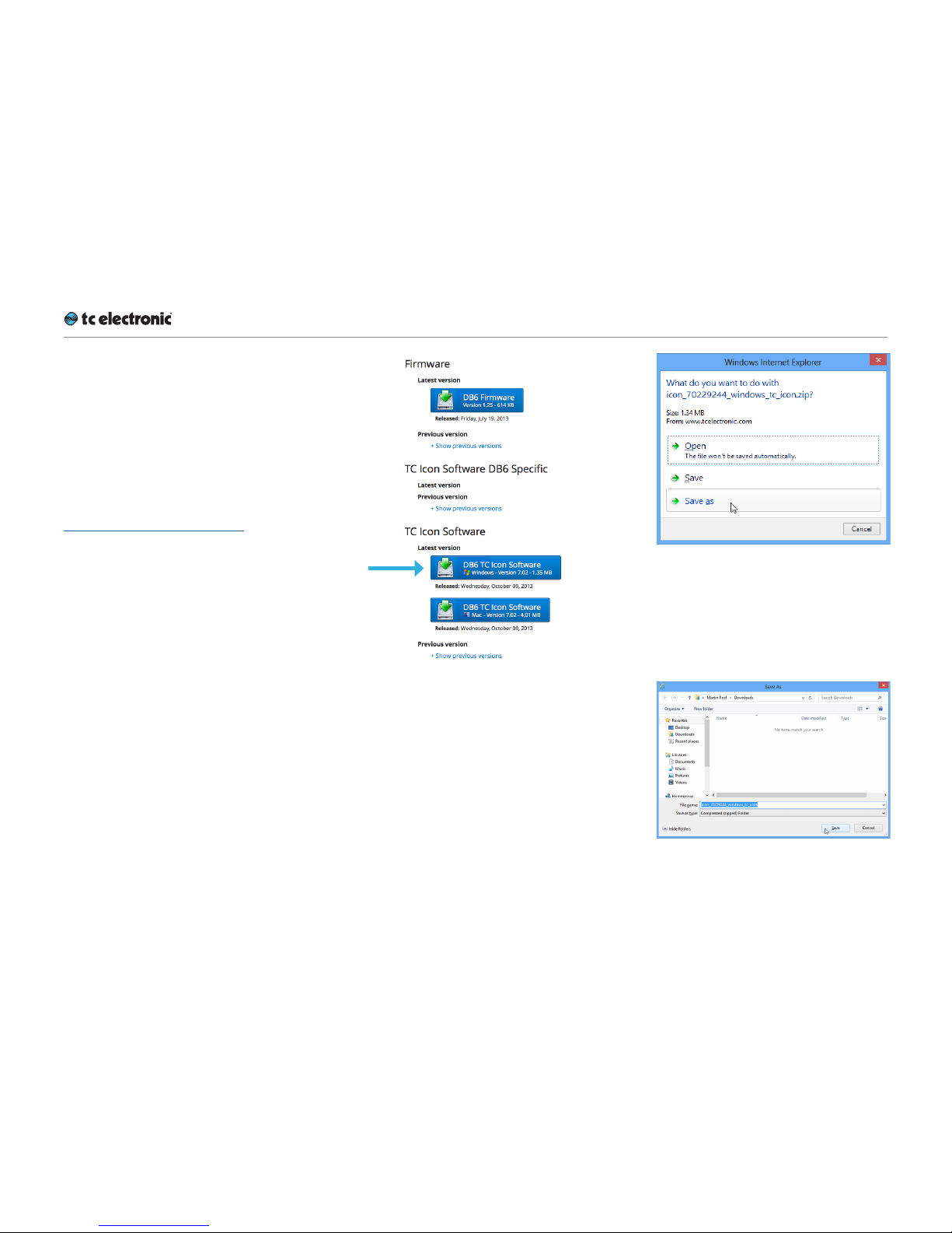
►
On this page, locate the “DB6” section.
►
In this section of the support page, look for
“TC Icon software” and click the button representing the latest version of the TC Icon
software for Microsoft Windows.
Depending on your browser type and con-
figuration, a dialog may be shown asking you
what you want to do with this file.
Choose “Save”.
The software will be downloaded to your
browser’s default download location. Usually,
this is the “Downloads” folder for your user
account.
►
Go to the folder containing the ZIP file you
just downloaded.
Page 17
Software: TC Icon and DB6 fir mware
DB6 English Ma nual (2014-10-07) 14
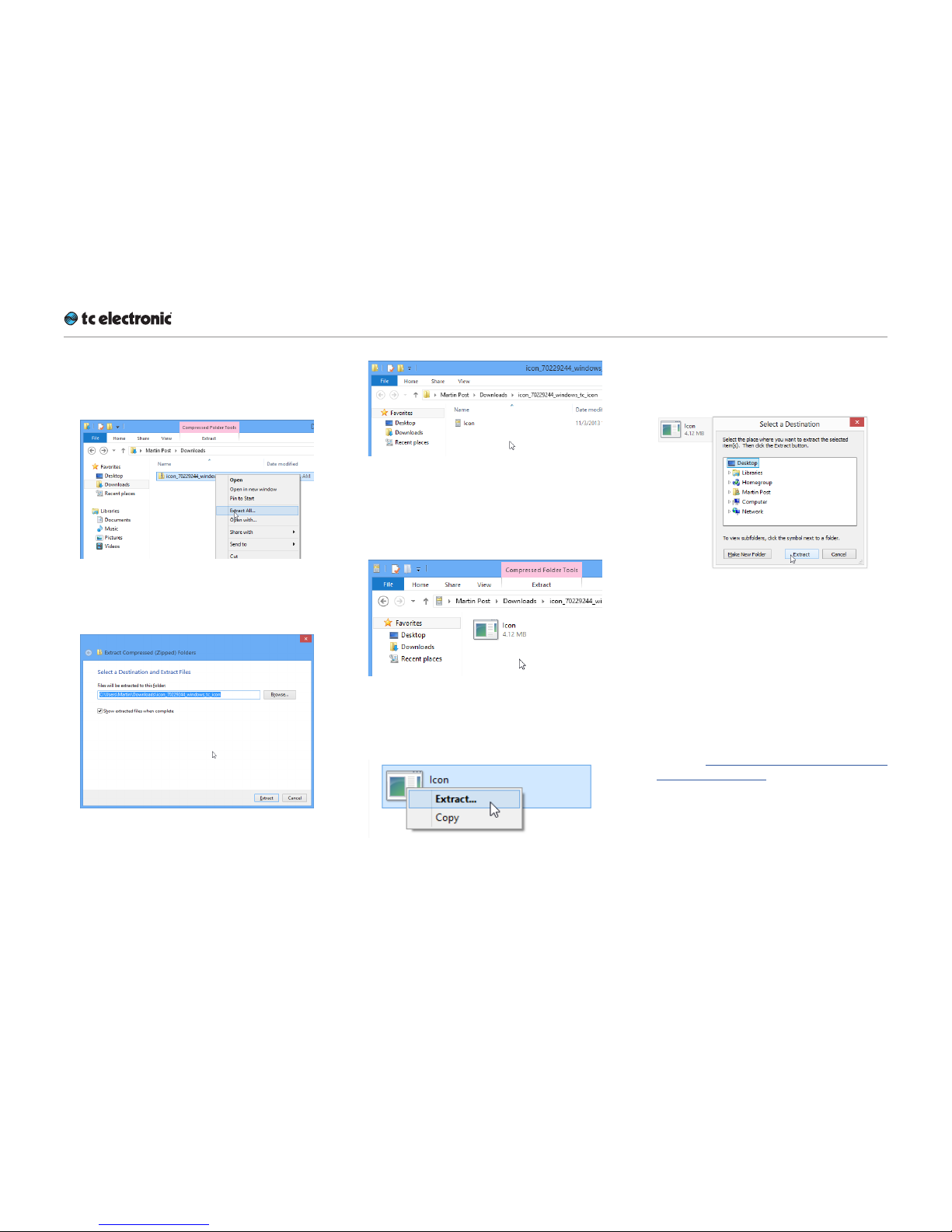
►
Right-click the .ZIP file and choose “Extract
All…“ from the context menu.
A dialog box will allow you to specify where
the extracted files should be stored.
Accept the defaults or change the path.
►
After extracting the ZIP file, you will see a
.CAB (“Cabinet”) file in Windows Explorer.
►
Double-click the .CAB file.
An “Icon” application file will be shown.
►
Right-click the “Icon” application file and
choose “Extract…“ from the context menu.
In the dialog box that is shown next (“Select
destination”), select a folder where you can
easily find the application – e.g., the Windows
desktop.
►
Click “Extract” to extract the application to
the selected destination.
►
Launch the TC Icon application that you just
extracted by double-clicking its icon.
TC Icon will try to establish connections to all
connected TCdevices on a local network, including your DB6.
If a connection cannot be established, please
refer to “Networking basics and troubleshooting” on page 34.
If you experience technical problems during
software download or installation, please ask a
person with administrator privileges on this computer for assistance.
Page 18

Software: TC Icon and DB6 fir mware
DB6 English Ma nual (2014-10-07) 15
Updating TC Icon software
To update the TC Icon software on your computer when a newer version is released,
►
quit the TC Icon software if it currently running on your PC,
►
download and extract the newer version as
described in this section and
►
replace the currently installed version by
copying the newer version over it.
Page 19

Software: TC Icon and DB6 fir mware
DB6 English Ma nual (2014-10-07) 16
Finding and installing
TCIcon software – OSX
The most current version of TC Icon software for
OSX at the time of production is provided on the
USB stick that came with your DB6, but you may
want to download the latest version from the TC
Electronic website.
You can download the latest version of the TC
Icon software for OSX from:
tcelectronic.com/support/software/
►
On this page, locate the “DB6” section.
►
In this section of the support page, look for
“TC Icon software” and click the button representing the latest version of the TC Icon
software for OS X.
Depending on your browser type and con-
figuration, a dialog may be shown asking you
what you want to do with this file. Choose
“S ave ”.
The software will be downloaded to your
browser’s default download location. Usually,
this is the “Downloads” folder for your user
account.
►
Go to the folder containing the file you just
downloaded.
►
If you are seeing a .ZIP file, double-click it to
extract its contents. However, your browser
may already have extracted the contents from
the .ZIP file automatically.
►
After the ZIP file has been extracted, you will
see a .DMG (“Disk Image”) file in the Finder.
►
Double-click the .DMG file to mount this disk
image.
An “Icon” disk image containing an “Icon”
app will be shown.
Page 20

Software: TC Icon and DB6 fir mware
DB6 English Ma nual (2014-10-07) 17
►
Copy the TC Icon application from the disk
image to your hard disk by dragging it to the
“Applications” folder, or to another folder
where you can easily find it.
►
You can now unmount (eject) the disk image
by right-clicking it and selecting “Eject” from
the context menu.
►
Launch TC Icon by double-clicking the application.
TC Icon will try to establish connections to all
connected TCdevices on a local network, including your DB6.
If a connection cannot be established, please
refer to “Networking basics and troubleshooting” on page 34.
If you experience technical problems during
software download or installation, please ask a
person with administrator privileges on this computer for assistance.
Updating TC Icon software
To update the TC Icon software on your computer when a newer version is released,
►
quit the TC Icon software if it currently running on your Mac,
►
download and extract the newer version as
described in this section and
►
replace the currently installed version by
copying the newer version over it.
Page 21

DB6: An introduction
DB6 English Ma nual (2014-10-07) 18
DB6: An introduction
Page 22

DB6: An introduction
DB6 English Ma nual (2014-10-07) 19
Thank you for choosing DB6 – the next step
in professional loudness control. We want
to thank you for choosing this product, and we
hope it will serve you as a reliable, flexible loudness processor for many years to come.
Consistency in loudness is the single most
important audio issue to get right in broadcast today. DB6 employs cutting-edge tech-
nology allowing stations to avoid listener complaints about jumping levels, while transmitting
both analog and digital signals with optimum
processing.
Keeping audio transparent
One of the finest things about new international
loudness standards is that a transparent signal
path is defined all the way from production to the
consumer. We therefore encourage you to take
advantage of DB6’s multiple ways of turning off
loudness processing for content that is already
normalized and suitable for a given platform.
Partial or full disabling of loudness processing
can be automatic or based on external signaling. TC has taken initiatives to make such external signaling part of open broadcast standards
– so expect new developments in this field. For
unknown content, rather than using DB6 to inflict “sausage processing”, use its built-in radar
meters to pull in loudness just enough. The goal
should not be to have all programs sit constantly
at Target level, but rather to have DB6 intervene
as a “safety belt” when something has gone
wrong upstream.
Production measurements such as Program
Loudness and Loudness Range will gradu-
ally make audio mixing more precise and downstream processing less needed. Therefore, review your processing settings at regular intervals, and be prepared to back them off as production catches up.
DB6 and AC3 transmission
DB6 includes numerous functions to optimize
sound and logging when delivering to platforms
using the AC3 codec. While fixed AC3 metadata
recommendations in new ATSC and EBU guidelines means that there are fewer things that can
go wrong, the dynamics processor built into the
AC3 decoder (known as “DRC”) is still one of
the places where audio transparency tends to
get lost.
To prevent DRC from becoming the “sausage
processing” component of the signal path, we
recommended turning it off. DRC also isn’t
BS.1770 compliant, and the limited 20 dB headroom in the “RF” path of AC3 can be dealt with
in better ways that are available in DB6.
Page 23

DB6: An introduction
DB6 English Ma nual (2014-10-07) 20
Signal path transparency check
Once a transmission signal path has been configured and adjusted, check that it is indeed
free of loudness processing when you think it
should be. A good indicator of this is Loudness
Range. Measure a program’s Loudness Range
in the production studio, and check if the value
stays the same when delivered to the consumer.
As long as no dynamics processing is applied,
Loudness Range does not change if a program
is offset in gain.
Loudness range is also robust even across lossy
data reduction unless a low bit rate (lower than
64 kbps) is used. For AC3 transmission, be sure
to check Loudness Range after a domestic decoder as the DRC system may unexpectedly be
engaged.
Solid foundations
TC’s involvement with high quality digital audio
dates back to the mid-eighties of the last century. Our commitment to digital excellence has
continued over the years with equipment for the
music, film and mastering industries. The advanced loudness and true-peak meters in TC’s
signal processors are founded on ITU and EBU
standards – standards that TC has contributed
to significantly.
Many years of experience with analog and digital broadcast and the know-how of skilled engineers: This is the foundation on which this product was built. From the purist and quality-conscious hardware engineers to the software writers, some of whom were involved with designing
the MPEG codecs: The team who has worked on
this signal processor forms a competent, nondogmatic design group ready to take broadcast
audio to the next level.
We are confident you will value the result of their
hard work.
One-step loudness management
DB6 is a signal processor that is able to handle
all aspects of loudness in one simple process:
►
loudness metering at the input stage,
►
up and/or down conversion at any stage,
►
loudness processing,
►
on-line lip-sync delay,
►
loudness metering at the output stage and
►
logging of all relevant loudness statistics.
In short: DB6 is an intelligent loudness processor
that keeps your audio at its finest – regardless
of which platform you need to deliver to. However, please note that DB6 is not a substitute for
managing loudness and true-peak level sensibly in production and linking. The best result is
obtained when production, ingest, linking and
transmission is a transparent loop where as little
adjustment as possible happens downstream of
production.
Page 24

DB6 – Basic concepts and operation
DB6 English Ma nual (2014-10-07) 21
DB6 – Basic concepts
and operation
Page 25

DB6 – Basic concepts and operation
DB6 English Ma nual (2014-10-07) 22
Operating DB6
DB6 is equipped with one or more signal processing cards. Each card encompasses four so-
called engines.
Two of these engines are running the Loudness
Wizard algorithms (see “Loudness Wizard” on
page 93), while the other two are running the
LM6 metering algorithms (see “LM2 (optional)”
on page 148 ).
As you can easily see, DB6 is a „headless system“ – it has no front panel controls (with the exception of the Reset button).
DB6 is operated using the TC Icon software,
which you can download from the TC Electronic
website.
You can use the same version of the TC Icon
software to operate DB6 and other professional
broadcast products from TC Electronic (e.g. DB4
and DB8MKII).
Accordingly, a significant part of this manual
covers operating DB6 using TC Icon software
running on a standard computer, and the screen
shots you see are taken from the OS X or Windows versions of this software.
DB6 offers a variety of ways to engage or disengage audio processing. Processing may be invoked automatically, depending on format, level,
physical inputs etc., while remote control can be
achieved via Ethernet, GPI, SDI metadata etc.
When setting up the device, make sure to
only engage the methods you wish to use. For
example, if GPI inputs are not used, make sure to
make sure to disable the respective input.
Please invest some time in learning TC Icon’s
basic concepts – you will benefit from it when
operating systems that may include many networked TC signal processors.
Hardware versions
DB6 is available in six different hardware versions: DB6 Single, DB6 Multi with one, two or
three 3G Transmission cards installed, and DB6
AES in balanced and unbalanced versions.
DB6 Single handles one SD/HD/3G stream,
making it the perfect choice e.g. for local broadcasters or as an intelligent loudness management tool in an OB van. DB6 single cannot be
expanded to handle more audio streams.
DB6 Multi comes with the ability to process one
stream right out of the box, but users can install
one or two additional 3G Transmission dualengine cards.
DB6 AES (balanced and unbalanced) gives you
up to 16 channels of unbalanced AES I/O on
BNC connectors. Depending on your integrated
transmission system, you may prefer to pass
your entire SDI signal through a loudness management system, or you may prefer to route only
the audio signal through an insert point. With
DB6 AES, you get the opportunity to choose the
latter scenario as well.
Page 26

DB6 – Basic concepts and operation
DB6 English Ma nual (2014-10-07) 23
Expanding your DB6
DB6 offers considerable flexibility in routing, analyzing and processing audio signals. To benefit
from this flexibility, you need to understand the
basic concepts and building blocks of the device
as outlined in this section.
The audio processing capabilities of your device
depend on the number of dual-engine cards/
processors (3G Transmission cards) installed.
Each 3G Transmission card…
►
can process one SDI audio stream
►
holds two multichannel processors
►
is capable of running…
– two LoudnessWizard™ algorithms or
– two LoudnessWizard 2™ algorithms
as well as
– two LM6 Loudness Radar Meters
simultaneously.
Accordingly, a DB6 Multi with two 3G Transmission cards can handle three independent
streams – making it the perfect high-density
solution for any TV station in need of processing
multiple streams simultaneously.
Extensibility is the only relevant difference
between DB6 single and DB6 Multi. Both ver-
sions feature the same high-quality hardware as
well as the same powerful software algorithms.
Instructions on upgrading a base DB6 Multi
with one or two Transmission 3G cards are
not part of this manual. They are provided in
a separate document that comes with the 3G
Transmission card.
DB6 SDI: The Serial
Digital Interface
With regards to inputs and outputs, DB6 SDI
is based on the Serial digital interface (SDI) – a
family of audio and video interfaces standardized by the Society of Motion Picture and Television Engineers (SMPTE).
An SDI signal may contain up to sixteen audio
channels (8 pairs) at 48kHz sample rate and 24
bit resolution.
We assume that you have a good working knowledge of SDI. The standard as such is not discussed in this manual.
Page 27

DB6 – Basic concepts and operation
DB6 English Ma nual (2014-10-07) 24
DB6 AES
For many years, TC Electronic has focused on
developing highly intelligent clocking solutions.
DB6 features one of the most complex and intelligent technologies we have ever made. It is
based on the TC developed DICE™ core with
its JET™ technology, which has been further refined to deliver important features specifically for
broadcast use.
►
DB6 locks really fast and artefact-free to
clock sources.
►
It sends as good an audio signal as possible
through at all times.
►
If the source is lost, DB6 keeps on running at
the “last good sync source rate”.
►
DB6 keeps outgoing clock inconsistencies
(e.g. when the sync reference is lost or the
sync source changes) to a minimum. This ensures that e.g. upstream source switching will
affect downstream devices to the least possible extent.
►
DB6 reduces incoming jitter to a nearly unmeasurable level.
SDI vs. AES
There are no versions of DB6 that provide SDI
and AES inputs and outputs on the same unit.
DB6 presets
DB6 comes with ready-to-use presets based
on international standards. More presets will be
made available as part of software updates from
the TC website. These presets are based on information from broadcasters around the world.
If you feel that an important preset is missing or
that a given preset does not work as it should,
please get in touch with TC Electronic technical
suppor t:
tcelectronic.com/support/
Page 28

DB6status indicators and ports
DB6 English Ma nual (2014-10-07) 25
DB6
status indicators and ports
Page 29
DB6status indicators and ports
DB6 English Ma nual (2014-10-07) 26
This section of the manual describes the device’s status indicators and connectors.
Please note that the number of front panel status indicators and connectors on the device depends on the hardware version you have purchased.
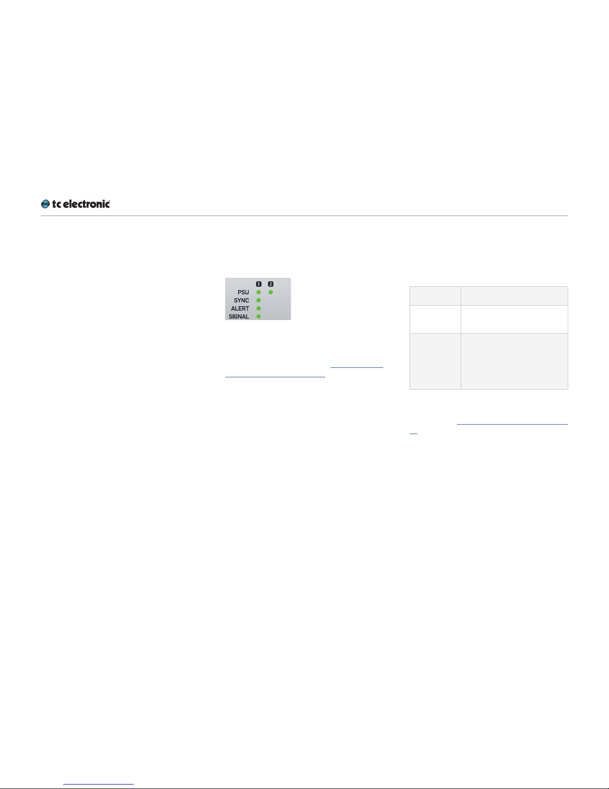
Front panel indicators
DB6 has the following front panel status indicators:
Fig. 15.: Front panel indicators on DB6 Single
Additional status information can be displayed
using TC Icon software – see “Obtaining DB6
status information” on page 47.
PSU 1 and PSU 2 LEDs
The PSU 1 and PSU 2 LEDs indicate the status
of the two built-in power supplies.
LED co lor /
indication
Status
Green An external power is connect-
ed and the power supply is fully functioning.
Red There is a problem with the
power supply. Either there is
no external power connected,
or there is a problem at certain checkpoints in the relevant
power supply.
Please refer to the descriptions of the PSU connectors in the “Back panel connectors” on page
29 section for more information.
Page 30
DB6status indicators and ports
DB6 English Ma nual (2014-10-07) 27
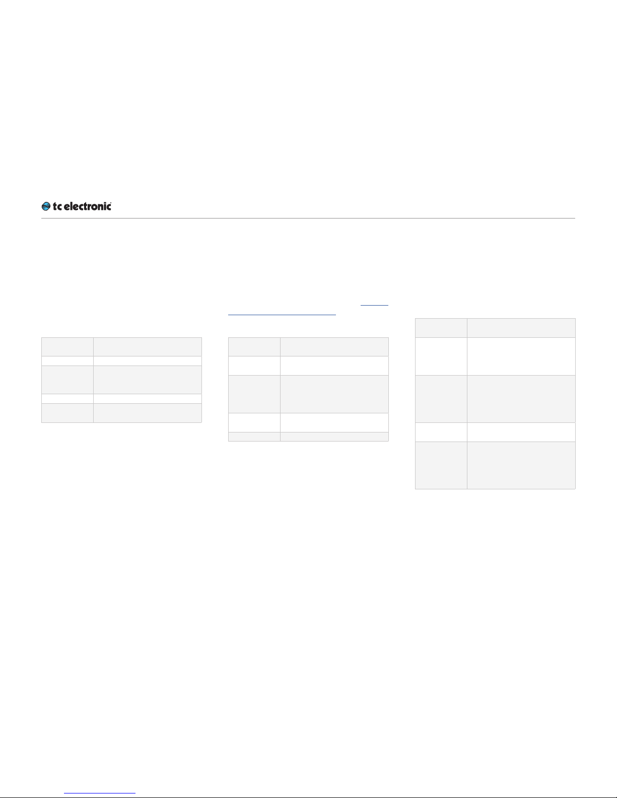
Sync LED(s) – SDI versions
DB6 Single has one Sync LED, while DB6 Multi
has three Sync LEDs – one for each of the up to
three cards/engines in the device.
The Sync LEDs indicate if synchronization to
the currently connected signal source has been
achieved.
LED co lor /
indication
Status
Off Startup – no lock achieved.
Green An SDI stream has been de-
tected at the corresponding in-
put, and DB6 is locked to it.
Yel l ow There is an SDI anomaly.
Red DB6 cannot lock to the SDI au-
dio stream.
Sync LED(s) – AES versions
The Sync LED of DB6 AES (balanced/unbalanced) indicates if synchronization to the signal source selected as Sync Source has been
achieved.
For a description of all Sync states, see “AES Input State indicators” on page 55.
LED co lor /
indication
Status
Off Startup – no lock achieved /
lock status unknown.
Green A clock signal has been de-
tected at the corresponding
AES input, and DB6 is locked
to it.
Yel l ow DB6 is following its internal
clock or set to Bypass.
Red No lock or Freewheel status
Alert LED
DB6 Single has one Alert LED, while DB6 Multi
has three Alert LEDs – one for each of the up to
three cards/engines in the device.
The Alert LEDs indicate problems either within
the device or with the signal being processed.
LED co lor /
indication
Status
Off DB6 is not connected to a
computer running the TC Icon
software or a hardware TC
Icon.
Green DB6 is connected to a com-
puter running the TC Icon software or a hardware TC Icon.
Normal operation, no problems
detected.
Green – blinking
Preset recall
Yel l ow There has been silence for
more than five seconds, or
the LM2/LM6 algorithm has
detected a “High Loudness”
state.
Page 31

DB6status indicators and ports
DB6 English Ma nual (2014-10-07) 28
Signal LED
DB6 Single has one Signal LED, while DB6 Multi
has three Signal LEDs – one for each of the up to
three cards/engines in the device.
The Signal LEDs indicate if audio streams are received and processed by DB6.
Detection for the Signal LEDs and GPO occurs
at the input.
LED co lor /
indication
Status
Off No audio signal (above
-70dBFS) has been detected.
Green An audio signal above
-70dBFS has been detected.
Yel l ow An audio signal above -1dBFS
has been detected.
Front panel reset button
The Reset button on the front panel can be used
to reset the IP address of a DB6 unit or to reset
Ethernet communication between DB6 and a
computer when a communication error has occurred.
Resetting the IP address
of a DB6 unit
It may be necessary to reset the IP address of a
DB6 unit. To do so, proceed as follows:
►
Switch off DB6 by disconnecting both power
supplies.
►
Insert a straightened paper clip or a similar
object into the “Reset” hole on the front panel
until it touches the button behind the panel.
►
Boot the DB6 by connecting one or both
power supplies while still holding the straightened paper clip onto the Reset button.
DB6 will boot using its default IP address. The
default IP address is 192.168.1.[xx], where [xx] is
the last two digits of the device’s serial number
as printed on its back.
Page 32

DB6status indicators and ports
DB6 English Ma nual (2014-10-07) 29
Resetting Ethernet communication
It may be necessary to reset Ethernet communication between DB6 and a computer during op-
eration. To do so, proceed as follows:
►
During operation, insert a straightened paper
clip or a similar object into the “Reset” hole
on the front panel until it touches the button
behind the panel, and press the button for
approximately 5 seconds until the LEDs start
blinking.
This will reset Ethernet communication with-
out interrupting audio streams.
Back panel connectors
Fig. 16.: Back panel connectors
on a DB6 Single
PSU (2 x)
DB6 has two C13 type power inlet sockets. The
dual power inlets provide extended operational
security and stability. They accept 100 to 230
Volts AC at 50/60Hz.
If possible, connect these two power sockets to
two independent power sources to minimize the
risk of power loss.
Due to the redundant design, DB6 will still be
fully operational when one of the two power supplies fails. However, to ensure maximum security
and stability, you should address the issue and
investigate the cause of the error indication at
the first given opportunity.
In case of complete power loss, the device is
hardware-bypassed via relays, ensuring that no
signal loss occurs.
Page 33

DB6status indicators and ports
DB6 English Ma nual (2014-10-07) 30
Ethernet interface(s)
DB6 is equipped with 32 bit Ethernet interfaces fully compliant with the IEE 802.3u standard, supporting 10 and 100 Mbit/s (100Base-TX
ports).
DB6 Single and DB6 AES have two Ethernet
ports, while DB6 Multi has either two, four or six
Ethernet ports, depending on the number of 3G
Transmission cards installed.
Connect a computer running TC Icon software
or a hardware TC Icon device to one of these
ports using a “straight-through” cable with 8P8C
modular connectors (“RJ45”). A “crossover” type
cable is not required.
The Ethernet ports are used exclusively for connecting a controller (namely a computer running
TC Icon software). No audio signals are transmitted for processing over Ethernet ports.
SDI In Port(s)
DB6 Single has one SDI In port, while DB6
Multi has either one, two or three SDI In ports,
depending on the number of 3G Transmission
cards installed.
DB6 AES (balanced/unbalanced) has no SDI In
ports.
Connect the upstream SDI device to an SDI In
socket on DB6. Use a coaxial cable with BNC
connectors with a nominal impedance of 75
Ohms.
Connecting multiple 3G cards
If you are using a DB6. with two or more 3G
Transmission cards installed, daisy-chain the
SDI cards as follows:
►
Connect your signal source to the SDI In port
of the first card.
►
Connect the SDI Out por t of the first card to
the SDI In port of the second card.
►
Connect the SDI Out por t of the second card
to the SDI In port of the third card (if applicable).
►
Connect the SDI Out por t of the third/last
card to the next downstream device.
Connecting the Transmission cards as described
here will have them show up as separate devices
in TC Icon. Select and configure each card to assign and process SDI streams as required.
Page 34

DB6status indicators and ports
DB6 English Ma nual (2014-10-07) 31
SDI Out Port(s)
DB6 Single has one SDI Out port, while DB6
Multi has either one, two or three SDI Out ports,
depending on the number of Transmission 3G
cards installed.
DB6 AES has no SDI Out ports.
Connect the downstream SDI device to an SDI
Out socket on DB6. Use a coaxial cable with
BNC connectors with a nominal impedance of
75 Ohms.
Unbalanced AES-3id In Ports
DB6 AES (Unbalanced) has 8 AES-3id In ports
on BNC connectors with one channel pair per
connector.
DB6 Single and DB6 Multi have no AES In ports.
Unbalanced AES-3id Out Ports
DB6 AES (Unbalanced) has 8 AES-3id Out ports
on BNC connectors with one channel pair per
connector.
DB6 Single and DB6 Multi have no AES Out
ports.
Fig. 17.: DB6 AES (unbalanced version)
back panel connectors
Page 35

DB6status indicators and ports
DB6 English Ma nual (2014-10-07) 32
Balanced AES In/Out Ports
DB6 AES (Balanced) has two Sub-D AES I/O
connectors, with channels 1-8 on the upper connector and channels 9-16 on the lower connector.
DB6 Single and DB6 Multi have no AES In ports.
Fig. 18.: DB6 AES (balanced version)
back panel connectors
About AES channels
DB6 AES (balanced/unbalanced) comes fully
loaded with 16 channels of unbalanced AES I/O,
and by default the first 8 channels are active.
Should you need even more channels, you can
purchase a separate license for activating channels 9-16. See “Extending your product’s capabilities with optional licenses” on page 160.
GPIO Port(s)
Connect a controller to this por t to control various DB6 features remotely.
For more information on GPI, see “DB6 remote
control” on page 58 and “Appendix 2: DB6
GPI/O page” on page 161.
Page 36

Setting up DB6
DB6 English Ma nual (2014-10-07) 33
Setting up DB6
Page 37

Setting up DB6
DB6 English Ma nual (2014-10-07) 34
DB6 can be used in a variety of configurations
and setups. However, as all TC Broadcast processors in your system can be controlled from a
single computer running TC Icon software, even
large and complex setups are basically operated in the same manner as the basic setup described in this chapter.
Networking basics and
troubleshooting
You may setup and operate your DB6 in a simple
networking environment – where you can connect a computer and one DB6 directly using a
standard Ethernet cable –, or your system may
be more complex, involving several computers,
several DB6 and other TC devices.
Either way, you are operating a system based on
TCP/IP – the same protocol suite the Internet is
built on. Accordingly, you need to follow basic
networking procedures when setting up your
system.
It is absolutely possible that a standard computer running the TC Icon software will detect a DB6
“out of the box” without problems. However, if it
doesn’t, there is most likely a subnet issue or an
IP address conflict. In this case, please refer to
the following sections.
Subnet mask and TCP/IP addresses
The subnet mask is a number that defines a
“group” of computers (or other devices) connected to a network. All units in this group must
have the same subnet mask.
The default subnet mask of each DB6 is
255.255.255.0.
The TCP/IP address of each device connected to a network has to be unique. An IP ad-
dress consists of four decimal numbers (ranging
from 0 to 255) separated by dots, e.g. 192.168.1.1
The first three numbers (e.g. “192.168.1”) must
be the same for each unit – but the remaining
number has to be unique in the subnet. I.e., no
two units in the subnet can have the same last
number.
The default IP address of each DB6 is
19 2 .16 8.1.[nn],
…where [nn] is identical to the last two digits in
the DB6’s serial number (you will find the serial
number of DB6 on a label on the rear side of the
device). This way, multiple DB6’s can be setup
directly out of the box without having to change
their IP numbers.
Page 38

Setting up DB6
DB6 English Ma nual (2014-10-07) 35
If your computer is using the same IP address
as a DB6 on the same network, you have two
options:
►
Alter the last octet (the last three numbers) of
your computer’s IP address or
►
Alter the last octet of the DB6’s IP address.
Changing your computer’s subnet
mask and TCP/IP address
If and where you can change the subnet mask
and IP address of your computer depends on…
►
the operating system you are using and
►
your account privileges.
In case of doubt, please consult your company’s
network administrator.
To find and change the TCP/IP
address and the subnet mask on
a computer running Windows:
►
Go to Control Panel / Network Connections / Internet Protoc ol (TCP/IP).
►
Set the TCP/IP address.
Fig. 19.: Windows Internet control panel
To find and change the TCP/
IP address and the subnet mask
on a computer running OSX:
►
Go to System Preferences / Network.
►
Select “Ethernet”.
►
Under “Configure IPv4”, select “Manually”.
►
Set the TCP/IP address.
Page 39

Setting up DB6
DB6 English Ma nual (2014-10-07) 36
Fig. 20.: OSX Network preferences
For further information, please refer to you operating system’s integrated help system.
Changing subnet mask and
TCP/IP address of a DB6
To change the subnet mask and TCP/IP address
of a DB6, you need to access it using a computer
running the TC Icon software. This means that
in case of an IP address conflict that keeps you
from accessing DB6 in the first place, you need
to change your computer’s IP first as described
in the previous section.
►
Launch the TC Icon software on your compu ter.
►
Select the particular DB6 you want to access.
►
Click on the Frame tab.
►
Select the System page.
►
Select the Setup subpage.
►
Select Net.
To change the IP address:
►
Select the IP address parameter.
►
Enter the new IP address.
►
Confirm by clicking Enter.
To change the subnet mask:
►
Select the IP Subnet Mask parameter.
►
Enter the new subnet mask.
►
Confirm by clicking Enter.
Page 40

Setting up DB6
DB6 English Ma nual (2014-10-07) 37
Resetting the IP address of a DB6
You may need to reset the IP address of a DB6.
This procedure is described in the section “Front
panel reset button” on page 28.
If the serial number of a particular DB6 ends with
“00”, the default IP address for this device will be
192.168.1.100, as “00” is not a valid IP number in
all networks.
There is a small risk that two DB6 (or other TC
signal processors) on a network have the same
last two digits in the serial number and thus will
conflict after a reset. To resolve this issue, reset
one DB6 first and change its IP address before
connecting the second DB6.
Quick Setup
This guide applies for a simple setup as illustrated below.
Ethernet
connection
Requirements for this setup are:
►
A DB6
►
A CAT5 Ethernet cable
►
A computer equipped with an Ethernet adapter, running Microsoft Windows or Mac OS X
and the latest version of TC Icon software.
Proceed as follows:
►
Unpack DB6 and install it in a stable, wellventilated space.
►
Connect DB6 and your computer using an
Ethernet cable.
►
Power up your computer and DB6.
►
If you have not already done so, download
and install the latest version of the TC Icon
software editor on your computer.
►
Launch the TC Icon software on your compu ter.
The following screen will appear:
►
Click “Assign”. The network is scanned, and
all connected and operational devices will be
listed on the next screen.
►
Select the device you wish to access.
►
To have TC Icon detect more devices and
assign them to one of up to eight slots, see
“Assigning devices to the available slots” on
page 89.
Page 41

Setting up DB6
DB6 English Ma nual (2014-10-07) 38
►
If you cannot access DB6, please refer to
“Networking basics and troubleshooting” on
page 34.
That’s it – you are now ready to configure and
operate your DB6.
Updating DB6 software
The latest version of both the DB6 software and
the TC Icon software editor available at the time
of production are supplied with your DB6.
However, from time to time, software updates
are made available by TC, containing both bug
fixes and new features.
Please download and install the most current
version of the TC Icon software from:
tcelectronic.com/support/software/
The TC Icon software is available for
►
Microsoft Windows and
►
Mac OSX.
Using TC Icon software, you can access your
DB6 and update its built-in software (the firmware), which is provided as a separate download.
Updating DB6 firmware is described in “Updating DB6 firmware” on page 79.
Page 42

Basic operation
DB6 English Ma nual (2014-10-07) 39
Basic operation
Page 43

Basic operation
DB6 English Ma nual (2014-10-07) 40
Introduction
This section of the manual is a general introduction to operating DB6 using the TC Icon software.
In the following chapters we assume that you
have connected DB6 and your computer directly
or as part of a network as described in “Setting
up DB6” on page 33.
Several DB6 and other TC signal processors
(e.g. DB4/DB8MKII), and computers running the
TC Icon software can be connected and operated at the same time as part of a standard Local Area Network (L AN). The TC Icon software is
used to detect, configure and operate devices
from your computer.
If you encounter communication errors or cannot
detect or operate a device properly, please refer
to “Networking basics and troubleshooting” on
page 34.
Basic TC Icon operation
The TC Icon software interface has been optimized for use in real-time situations in broadcast
and post production environments (which usually are very different from standard desktop computing tasks and environments). Accordingly,
buttons are very prominent and clearly labelled
to ensure proper operation even in stressful situations. In addition, important parameters can be
assigned to on-screen faders, allowing for precise control and immediate visual feedback.
The interface can be customized. Customizable
parameters include fader positions and user interface colors. For more information, please refer
to the chapters ““UI page” on page 91” and
“Color page” on page 91 of this manual.
TC Icon interface: Tabs versus pages
►
Use the tab buttons on the upper edge of the
TC Icon window to select a primary group of
functions.
►
Use the page buttons on the left edge of the
TC Icon window to select specific pages.
Page 44

Basic operation
DB6 English Ma nual (2014-10-07) 41
TC Icon modes: Base and
Device operation
The TC Icon software has two operation modes:
Base and Device operation.
►
Use Base mode to select devices and configure the network and the TC Icon software
itself.
In Base mode, you will see the Select, Auto
and Setup tabs on the upper edge of the
TC Icon window. Most Base mode functions
are described in the chapter “Icon Setup” on
page 87.
►
Use Device operation mode to operate the
currently selected device.
In Device Mode, you will see the specific tabs
for operating the currently selected TC device.
Switching between Base and
Device operation modes:
►
To switch between Base and Device operation modes, click the Icon symbol in the upper left corner of the window.
Faders
The TC Icon software has large on-screen faders. They have several features that will help you
operate your DB6 efficiently.
►
There are six on-screen faders.
►
You can change the position of the faders
or hide them completely – see“UI page” on
page 91.
►
The name of the parameter that a fader is
currently assigned to is displayed above the
fader.
►
When no label is shown above a fader, that
fader is currently not assigned to a parameter.
►
Fader assignments and values will always reflect the last Engine you have accessed.
Using Faders for fine adjustments
When a parameter is assigned to a fader, you
can choose between Normal and Fine adjust-
ment mode.
►
In Normal Adjustment mode, the fader
range will cover the full parameter range – e.g.
-18dB to 18dB for the Center Trim parameter.
►
In Fine Adjustment mode, the fader range
will be smaller, allowing you to fine-tune
around the current value – e.g. in 0.1dB steps
for a level parameter.
To switch a fader from Normal Adjustment mode
to Fine Adjustment mode or back, click the label
above that fader. Fine Adjust mode will be indicated by two triangles in the label field.
Fig. 21.: Fader label indicating Fine
adjustment mode
Page 45

Basic operation
DB6 English Ma nual (2014-10-07) 42
Fader Groups
DB6 algorithms encompass many parameters
on several pages. For efficient operation, the
most important parameters can be assigned to
the on-screen faders in Fader Groups. Fader
Groups allow you to access the most important
features immediately, no matter what particular
page is currently being displayed.
Fig. 22.: Fader group 1 selected in
the Fader Group selector
You can access predefined Fader Groups that
cover typical applications, and you can define a
User Fader Group with your own assignment for
each fader.
You can select and customize Fader Groups per
Engine – meaning that you can use one group of
fader assignments for Engine 1, and another one
for Engine 2.
To select a Fader Group:
►
Select the tab of an Engine (on the top edge
of the TC Icon software window).
►
Use the arrow buttons on the Fader Group
selector (on the left edge of the TC Icon software window) to select the desired Fader
Group. The name of the currently selected
Engine and Fader Group are displayed on
the Fader Group selector. E.g., “E1 Group 1”
means that you have selected the predefined
Fader Group 1 for Engine 1.
To set up the User Fader Group:
►
Select the tab of an Engine (on the top edge
of the TC Icon software window).
►
Use the arrow buttons on the Fader Group
selector to select the “User” Fader Group.
►
Click the “Fader Asgn” button (on the left
edge of the TC Icon software window).
►
Click the label of a fader that you want to assign to a parameter.
►
Click the name of the parameter that you want
to assign to the previously selected fader.
►
Repeat the last two steps until you have made
all desired assignments.
►
Click the “Fader Asgn” button again.
Assigning Fader 6 on the fly
Even when using one of the predefined Fader
Groups for an Engine, you can always assign the
sixth Fader to whatever parameter you want to
control in a given situation. Like all other Faderrelated settings, this is an Engine-specific setting: You can assign Fader 6 to one parameter
when Engine 1 is selected and to another parameter when Engine 2 is selected.
To assign a parameter to fader 6:
►
To assign a parameter to the fader 6, simply
click on a parameter field. That parameter will
immediately be assigned to the sixth fader. If
that parameter is also assigned to one of the
other faders, you can now use both faders to
control that parameter.
Page 46

Basic operation
DB6 English Ma nual (2014-10-07) 43
On-screen keyboard
DB6 allows you to store and rename presets, assign labels to inputs and outputs and perform
other functions where text input is required.
When you access one of these functions, an onscreen keyboard will be displayed.
Fig. 23.: TC Icon software – On-
screen keyboard
While they keyboard is being displayed, you can
either click the letters shown on-screen or use
your computer’s keyboard for character input.
When you are done, click the large Enter button
or press your computer keyboard’s Enter key.
Page 47

Accessing DB6
DB6 English Ma nual (2014-10-07) 44
Accessing DB6
Page 48

Accessing DB6
DB6 English Ma nual (2014-10-07) 45
►
Connect your computer and DB6 as described in the “Setting up DB6” ch apt er.
►
Power up your computer and your DB6.
►
On your computer, launch the TC Icon software.
►
When you do this for the first time or the system configuration has been changed, the following screen will appear:
►
Click “Assign”.
►
All currently connected TC signal processors
that are supported by the TC Icon software
should be detected and assigned to one of
the eight on-screen slots/locations.
►
If a connected device is not detected, please
refer to “Networking basics and troubleshooting” on page 34.
►
Click the icon representing the DB6 to access it.
Operating multiple
computers and/or TC HD
devices in one network
In a more complex setup with multiple TC Icon
hardware remote controls and/or several networked computers running TC Icon software,
each of these TC Icon units and computers can
be used to connect to TC HD devices (System
6000 MKII, DB6, Loudness Pilot, UpCon) on this
network.
If your setup contains multiple TC HD devices,
you should name these devices unambiguously
so you don’t accidentally edit the settings of the
wrong device.
Page 49

Accessing DB6
DB6 English Ma nual (2014-10-07) 46
Scanning / rescanning a
network for devices
The scenario described above covers the first
time you boot up your system or when no connected units are assigned.
When…
►
you make changes to your setup,
►
when devices are powered up or down, or
►
if there are connection errors, these may not
be detected immediately.
In this case, you should scan the network again.
To scan a network for devices:
►
In the TC Icon software, go to Setup / Devices
►
Click the Detect button.
For further information, see “Devices page” on
page 89.
In the following sections of this manual, we assume that you are operating a basic system with
only one DB6 connected.
Page 50

Obtaining DB6 status information
DB6 English Ma nual (2014-10-07) 47
Obtaining DB6 status
information
Page 51

Obtaining DB6 status information
DB6 English Ma nual (2014-10-07) 48
Please note that the LEDs on the front of a DB6
will display basic status information as long as
the device is powered – see “Front panel indicators” on page 26.
Additional status information can be obtained
using TC Icon, where you can also define how
certain error states should be indicated on the
device.
To display status information about DB6, go to
Frame / System / Status.
Fig. 24.: DB6 Single/Multi Status page
This page will display the following status information:
Clock section
Source indicator
Indicates the source of the clock signal DB6 is
currently following.
Lock indicator
Indicates wether synchronization has been
achieved. If no synchronization has been
achieved, a red LED will be shown in this field.
Nominal Rate indicator
Shows the detected sample rate of the signal
DB6 is synced to.
Status section
Power indicator
Displays the current state of the DB6 power supplies.
A power supply failure may be indicated as described under “Power Warning parameter” on
page 48.
Power Warning parameter
A failing supply is always indicated by a red LED
on the front panel of the device. TC Icon can also
indicate a failing power supply, depending on the
setting of the “Power Warning” parameter.
“Off” setting
A failing power supply is not reported in the Icon
remote app.
“Warning” setting
A failing power supply is indicated by a yellow
“Power” label in the respective DB6 Frame indicator, and a yellow LED will be shown on the
Frame tab when it is selected.
“Error” setting
A failing power supply is indicated by a red
“Power” label in the respective DB6 Frame indicator, and a red LED will be shown on the Frame
tab when it is selected.
Page 52

Obtaining DB6 status information
DB6 English Ma nual (2014-10-07) 49
Sync indicator
The states and color codes shown here are the
same as those shown by the respective DB6
Sync LED on the front panel of the device – see
“Sync LED(s) – SDI versions” on page 27.
Alert indicator
The states and color codes shown here are the
same as those shown by the respective DB6
Alert LED on the front panel of the device– see
“Alert LED” on page 27.
Frame Identification parameter
If you are operating a complex system with multiple DB6 units, you may need to identify one
specific unit quickly. To do so, select the respective Frame using TC Icon software and then use
the Frame Identification parameter to have that
Frame identify itself with blinking Alert LEDs as
follows:
“Off” setting
This is the default setting. The Alert LED operates as described in “Alert LED” on page 27.
“Green/Off”, “Yellow/Off”, “Red/Off”, “Green/
Yellow”, Green/Red”, “Yellow/Red”
The Alert LED on the front panel of the respective Frame will blink in the chosen color/color
combination, while the Alert indicator field will
read “LED blinking”.
Signal indicator
The states and color codes shown here are the
same as those shown by the respective DB6
Signal LED on the front panel of the device – see
“Signal LED” on page 28.
Page 53

Obtaining DB6 status information
DB6 English Ma nual (2014-10-07) 50
Temperature indicator
Shows the current internal temperature of DB6 in
degrees Celsius.
Page 54

Setting up au dio and syncing
DB6 English Ma nual (2014-10-07) 51
Setting up audio and syncing
Page 55

Setting up au dio and syncing
DB6 English Ma nual (2014-10-07) 52
I/O Setup – DB6 Single
SDI and DB6 Multi SDI
To set up audio, go to Frame / System / I/O / SDI.
Use this page to…
►
display information about incoming audio,
►
select audio for processing and
►
change Advanced SDI settings.
Fig. 25.: I/O setup – SDI page
(DB6 Single and DB6 Multi)
SDI Status indication section
Lock status indicator
The Lock status field shows the top-level lock
status of an incoming SDI stream.
►
When DB6 is locked to an acceptable SDI
stream on the SDI input, “Lock” is shown.
►
When no acceptable SDI stream is available
on the SDI input, “No Lock” and a red LED
will be shown in this field.
Format indicator
When the DB6 is locking to an incoming SDI
stream, the Format indicator field will show the
format – e.g. “1080i59.94 HD”. If the DB6 is not
locking to any incoming SDI stream, the Format
indicator field will read “N/A”.
Available Groups indicators
SDI with embedded audio carries up to 16 channels of audio, divided into four groups. Accord-
ingly, each group carries four channels of audio.
The four Available Groups indicators show which
audio groups are available in the incoming SDI
stream for metering and processing. The onscreen LED for each available group will light up
in green. If the DB6 is not locking to an incoming
SDI stream, all indicators are turned off.
Audio (In) Groups selector
Settings: “Groups1+2”/“Groups3+4”/“Groups
1+3”/“Groups1+4”/“Groups2+3”/“Groups2+4”
Use the Audio Groups selector to select audio
groups for metering and processing.
! Please note that DB6 always receives two of
the audio groups in the incoming stream. The
unprocessed audio groups are bypassed bittransparently, as well as all related SDI packets such as video time code, close captions
etc.
Page 56

Setting up au dio and syncing
DB6 English Ma nual (2014-10-07) 53
Advanced SDI Mode section
The Advanced SDI Mode section of the I/O SDI
page contains SDI-related settings that you
would normally not have to change.
Advanced settings switch
To change Advanced SDI settings, click the Advanced button in the Advanced SDI Mode section of this page.
! Please note that switching off access to Ad-
vanced SDI settings will reset all parameters
in this section to their default values.
Clock Mode parameter
With SDI standards constantly evolving, chances are that upstream equipment treat audio and
video sync differently – e.g., a device may only
pay attention to one or the other. As this may
cause occasional disruption of sound, picture or
both, a problem may be difficult to trace without
measurement equipment monitoring SDI traffic for weeks or months. To diagnose a potential
problem, DB6 offers a diagnostic mode, which
may be tried after consulting TC support. To activate diagnostic mode, set the Clock Mode parameter to Diagnostic.
In Diagnostic mode, the DB6 will disregard the
audio clock information included in the audio
packets in the SDI stream and de-embed the audio based on the video clock only.
! Use the Diagnostic setting for diagnostic pur-
poses only.
Audio Out Groups parameter
Use the Audio Out Groups parameter to define if
and how the group assignment of the processed
audio signals should be changed.
Follow In Group setting
The processed audio signals will be assigned to
the same audio channel groups at the SDI output that were selected using the Audio Groups
selector. This is the default setting which is also
used when Advanced SDI mode has not been
activated.
Settings: “Groups1+2”/“Groups3+4”/“Groups
1+3”/“Groups1+4”/“Groups2+3”/“Groups2+4”
The processed audio signals will be assigned
to the selected audio channel groups at the SDI
output.
If you are using this parameter to reassign audio
channels to other groups, make sure that you are
processing the right audio groups downstream.
Rate Detect Mode parameter
Use the Rate Detect Mode parameter to specify
how DB6 should behave when receiving SD, HD
and 3G signals. By narrowing the range of formats acceptable to the DB6, lock-up time may
be optimized.
Automatic setting
When you set the Rate Detect Mode parameter
to Automatic, DB6 will accept all SDI formats:
SD, HD and 3G. This is the default setting which
is also used when Advanced SDI mode has not
been activated.
SD only setting
When you set the Rate Detect Mode parameter
to SD, DB6 will only accept the SD format and
not consider locking to HD or 3G signals. This
results in optimal lock-up time for SD signals.
HD only setting
When you set the Rate Detect Mode parameter
to HD, DB6 will only accept the HD format and
not consider locking to SD or 3G signals. This results in optimal lock-up time for HD signals.
3G only setting
When you set the Rate Detect Mode parameter
to 3G, DB6 will only accept the 3G format and
not consider locking to SD or HD signals. This
results in optimal lock-up time for 3G signals.
Stream 3G LevelB selection parameter
With 3G Level B SDI (SMPTE424M), 32 audio
channels in 8 audio groups are available via two
streams. Use the Stream 3G LevelB parameter
to select the stream that DB6 should de-embed/
embed audio from and to.
Page 57

Setting up au dio and syncing
DB6 English Ma nual (2014-10-07) 54
! Please note that when running 3G Level B,
data stream 1 and data stream 2 need to have
the same bit width so DB6 can de-embed and
process audio. I.e., both data streams need to
contain 8-bit data, or both data streams need
contain 10-bit data). If the bit widths of the
two data streams differ, DB6 will not be able
to de-embed and process audio.
Stream 1 setting
The DB6 will de-embed and embed two of the up
to four available audio groups in stream 1. This is
the default setting which is also used when Advanced SDI mode has not been activated.
Stream 2 setting
The DB6 will de-embed and embed two of the
up to four available audio groups in stream 2.
Bypass button
Settings: Enabled, Disabled
Use the Bypass button to immediately activate a
hardware bypass of the SDI signal, allowing it to
pass through DB6 unprocessed.
Page 58

Setting up au dio and syncing
DB6 English Ma nual (2014-10-07) 55
I/O Setup – DB6 AES
To set u p audio, go to Frame / S ystem / I/O / AES.
Use this page to…
►
display information about incoming audio,
►
set the sync signal source
►
change Advanced AES settings.
Fig. 26.: I/O setup – AES page (DB6 AES)
AES section
Lock status indicator
Lock status states: Lock, No lock,
Freewheel, Internal, Bypassed
The Lock status indicator shows the overall reference clock status. The colors of the “LED” in
this field represent the Icon application warning/
error scheme, which is used for alarms on e.g.
Icon, the DB6 front UI, GPO and SNMP.
►
“Lock” (green LED / OK ): DB6 has obtained
lock to the reference signal set in the Sync
Source field.
►
“No Lock” (red LED / Error): “No Lock” is typically displayed when there is no signal present on the Input that DB6 is set to lock to, or if
the incoming sample rate is outside the legal
range (48 kHz +1.7% / -1.3 %) and the Clock
Fallback parameter is set to Halt.
►
“Freewheel” (red LED / Error): “Freewheel” is
displayed when there is no signal present
on the Input that DB6 is set to lock to, or if
the incoming sample rate is outside the legal
range (48kHz +1.7% / -1.3%) and the Clock
Fallback is set to Freewheel.
►
“Internal” (yellow LED / Warning): “Internal” is
displayed when DB6 is set to sync to its internal referenced master clock at 48.000 kHz.
►
“Bypassed” (yellow LED / Warning): “Bypassed” is displayed when the DB6 hardware
bypass relay has been activated.
Sample Rate indicator
The Sample Rate indicator field displays the
sample rate of the sync source DB6 is currently
following. Sample rate is measured and displayed with 1Hz precision (21PPM @ 48kHz).
AES Input State indicators
Indicator states: Green, yellow, grey
The AES Input State indicators show the status
of the AES inputs. States are displayed as follows:
►
Green: A green “LED” indicates that a signal
is present and synchronous at the respective
input.
►
Yellow: A yellow “LED” indicates that a sig-
nal is present and running asynchronously
relative to the sync source. This typically happens when the upstream device is running at
an internal master clock rate and is not locked
to the house clock.
►
Grey: A grey “LED” indicates that no signal is
present at the respective input or that the incoming sample rate is outside the legal range
(48 kHz ±0.38%).
Page 59

Setting up au dio and syncing
DB6 English Ma nual (2014-10-07) 56
Sync Source
Settings: AES 1/2, AES 3/4, AES 5/6, AES 7/8,
AES 9/10, AES 11/12, AES 13/14, AES 15/16*
Use the Sync Source parameter to select the
signal source that DB6 should sync to.
Please note that channel pairs from 9/10 to 15/16
are only available as Sync Sources when you
have the optional AES 16ch license. For more
information, see “Extending your product’s capabilities with optional licenses” on page 160.
When the Clock Master parameter is set to “Internal”, the Sync Source setting is irrelevant.
However, you should be aware that you can use
this parameter to pre-select a sync source that
will be used when you switch DB6 AES directly
from Internal to External Sync.
Advanced Mode section (AES)
The Advanced AES Mode section contains additional AES-related settings.
Fig. 27.: I/O setup – AES page (DB6 AES)
with Advanced settings activated
Advanced settings switch
To change advanced AES settings, click the Advanced button in the Advanced Mode section of
this page.
! Please note that switching off access to Ad-
vanced AES settings will reset all parameters
in this section to their default values.
Clock Master parameter
Settings: External (default), Intern. 48 kHz
Use the Clock Master parameter to set whether
DB6 should be referencing an incoming external clock source or an internal crystal running at
48kHz.
►
External reference is mandatory in a broadcast installation and therefore the default setting.
►
Internal is typically only for test and laboratory use.
Clock Fallback parameter
Settings: Freewheel (default), Halt
Use the Clock Fallback parameter to set how the
internal clock of DB6 should be applied when the
external sync source is not present.
►
Freewheel: When sync is lost and the Clock
Fallback parameter is set to Freewheel, the
DB6 will continue running on the “last good
rate”. If possible, DB6 will run on a 96 bit precision version of the last good sample rate
that the DB6 received. This will only generate few sample slips downstream and on the
inputs (which may still receive audio) so the
audio quality is not significantly reduced. In
some borderline cases it may not be possible
to calculate the last good incoming sample
rate. In such a situation, the DB6 will revert to
the internal 48 kHz clock and audio will still
be sent through. Expect more sample slips in
such a situation.
►
Halt: When the sync source is not present
and the Clock Fallback parameter is set to
Halt, all AES outputs are turned off – meaning
no audio data and no AES carrier (no clock)
are being sent out. Use this setting if you prefer to stop audio and clock output completely
Page 60

Setting up au dio and syncing
DB6 English Ma nual (2014-10-07) 57
in a reference sync error situation. In this situation, the input signals are also turned off,
and accordingly, meter activity will cease.
With both settings, DB6 will revert to the reference input signal (as set with the Sync source
parameter) once it becomes available again. The
changeover will be handled as smoothly as possible on both audio and clock.
Bypass button
Settings: Enabled, Disabled
Use the Bypass button to immediately activate a
hardware bypass of the SDI signal, allowing it to
pass through DB6 unprocessed.
Setting up audio dithering
To set up audio dithering, go to Frame / System / I/O / Dither.
Fig. 28.: System – I/O – Dither page
Use the Dither page to set up if and how audio
signals should be dithered.
Dither out parameters
Setting “Off ” (no dithering applied),
24 bit, 20 bit, 18 bit , 16 bit
Use the Dither out parameters to configure dithering for each pair of audio signals.
By default, the Dither Out parameters swill be
shown for channel pairs 1/2, 3/4, 5/6, and 7/8.
Please note that channel pairs from 9/10 to 15/16
are only available as Sync Sources when you
have the optional AES 16ch license. For more
information, see “Extending your product’s capabilities with optional licenses” on page 160.
! If you are handling data-reduced formats, be
sure to set these parameters to “Off”.
Page 61

DB6 remote control
DB6 English Ma nual (2014-10-07) 58
DB6 remote control
Page 62

DB6 remote control
DB6 English Ma nual (2014-10-07) 59
DB6 provides extensive remote control features.
GPI and SDI metadata allow you to tailor remote
control to your station’s demands.
Remote – Master
The Remote Master page provides an overview
of the current remote control setup. It also allows you to enable the remote control features
(via GPI or SDI metadata) that you want to use.
Scene Recall section
GPI input 1 can be used for User Scene preset recall (see “Librar y – Recall page” on page
74).
Please not that the Icon user interface is locked
when GPI is used for control.
GPI button
Use this button to enable GPI 1 input for User
Scene Recall.
An “Enable” button that controls the same function can be found on the Remote – GPI page in
the GPI 1 – Scene Recall section.
Current Scene status field
The Current Scene status field shows the name
of the currently active Scene preset. The currently active Scene will be shown here wether it has
been selected via GPI or not. The name shown
here is identical to that shown on the Library –
Recall – Scene page as “Current” and on top of
the Frame – Routing page. When GPI is disabled,
“-“ is shown.
Page 63

DB6 remote control
DB6 English Ma nual (2014-10-07) 60
Processing section
Audio processing in your DB6 can be controlled
via GPI or SDI metadata.
When GPI or SDI metadata are being used to
control the device, a blue LED on the respective
Engine pages will indicate that their features are
remote-controlled.
GPI and SDI buttons
Use these buttons to activate audio processing
remote control via GPI 2 input or incoming SDI
metadata.
Please note that this is a “radio button” set – only
one of them can be active at a time.
“Enable” buttons that control the same function
can be found on the Remote – GPI page (in the
GPI 2 – Processing Control section) and on the
Remote – SDI page.
Current Processing status field
The Current Processing status field shows the
current audio processing details no matter if GPI
or SDI metadata is used for control.
“Normal” display
If “Normal” is displayed, audio-processing is not
remote-controlled, and the unit works as specified by the current Engine preset.
“N/A” display
“N/A” (“not available”) indicates that the currently selected function is not available/applicable
to the algorithm currently loaded in the Engine.
E.g., “Profile A/B” is only available as par t of the
Loudness Wizard 2 algorithm, which requires a
separate license.
“N/A” also indicates that the device is not remote-controlled, and the unit works as specified
by the current Engine preset.
Other displays
All other values shown in the Current Processing status field show which features are currently
controlled via GPI or SDI. The possible values
are a combination of the parameters Function,
Engine and Status as set on the Remote – SDI
or Remote – GPI page in the GPI 2 – Processing
Control section.
When using SDI, the same information is shown
on the Remote – SDI page in the Current Processing status field.
Resetting section
GPI can be used to reset audio processing history, meter history, or both.
When GPI is enabled, blue LEDs on the Engine
and Meter pages’ Reset buttons will indicate that
this feature is remote-controlled.
GPI button
Use this button to enable GPI 3 input for remote
control of the Reset function.
An Enable button that activates the same feature
can be found on the Remote – GPI page in the
“GPI 3 – Resetting”.
Resetting status field
The Resetting status field shows the current Reset status, no matter wether if it is controlled by
GPI or not.
“Idle” display
The device is not remote-controlled, or it is waiting for a GPI pulse. See below for details regarding the control pulse.
“Resetting xx” display
When the device receives a GPI pulse, this status is shown for one second. The “xx” value is a
combination of Function (audio processing and
meter) and Engine.
Page 64

DB6 remote control
DB6 English Ma nual (2014-10-07) 61
Remote – GPI GPI 1: Scene Recall section
Enable button
Use this button to enable GPI 1 input for User
Scene Recall.
A “GPI” button that controls the same function
can be found on the Remote – Master page in
the Scene Recall section.
Please note that the Icon user interface is locked
when GPI is used for control.
Function parameter
Use the Function parameter to define the scope
of the GPI recall feature.
The available GPI recall modes that you can set
using the Preset Recall Function parameter are:
Off setting
No Preset Recall using GPI.
2 Presets setting
Select one of two Presets using GPI1.
Select the Preset Bank using the Scene Bank
parameter.
3 Presets setting
Select one of three Presets using GPI1.
Select the Preset Bank using the Scene Bank
parameter.
For a description of the “Idle” state, see “Idle
state” on page 62.
4 Presets setting
Select one of four Presets using GPI1.
Select the Preset Bank using the Scene Bank
parameter.
7 Presets setting
Select one of seven Presets using GPI1.
Select the Preset Bank using the Scene Bank
parameter.
For a description of the “Idle” state, see “Idle
state” on page 62.
8 Presets setting
Select one of eight Presets using GPI1.
Select the Preset Bank using the Scene Bank
parameter.
3 Presets DUAL setting
Select one of three Presets using GPI1 and GPI2.
This mode uses simple binary inputs on GPI1
and GPI2 – i.e. 00, 01, 10 and 11.
Page 65

DB6 remote control
DB6 English Ma nual (2014-10-07) 62
For a description of the “Idle” state, see “Idle
state” on page 62.
Select the Preset Bank using the Scene Bank
parameter.
4 Presets DUAL setting
Select one of four Presets using GPI1 and GPI2.
This mode uses simple binary inputs on GPI1
and GPI2 – i.e. 00, 01, 10 and 11.
Select the Preset Bank using the Scene Bank
parameter.
15 Presets DUAL setting
Select one of fifteen Presets using GPI1 and
GPI2.
This mode uses 8-state on GPI1 and binary on
GPI2.
For a description of the “Idle” state, see “Idle
state” on page 62.
In this mode, the Scene Presets are always recalled from two consecutive banks – e.g. Bank 1
and Bank 2.
Select the Preset Bank pairs (1+2, 3+4 etc.) using
the Scene Bank parameter.
16 Presets DUAL setting
Select one of sixteen Presets using GPI1 and
GPI2.
This mode uses 8-state on GPI1 and binary on
GPI2.
In this mode, the Scene Presets are always recalled from two consecutive banks – e.g. Bank 1
and Bank 2.
Select the Preset Bank pairs (1+2, 3+4 etc.) using
the Scene Bank parameter.
Idle state
“Idle” denotes GPI control being presently not
active – i.e. the unit can still be controlled as normal, adjusting parameters and recalling presets
via Icon. However, once a non-idle GPI state is
chosen, the selected Scene preset is recalled,
and normal functionality is blocked (which is also
the case when GPI is engaged in general).
Scene Bank parameter
If you have set the previously described Function
parameter to any value other than “Off”, you can
select the Bank (or Banks) that Presets should
be chosen from using the Scene Bank parameter. See the recall modes for a more thorough
explanation.
Status field
The status field is intended for diagnostics during the setup of GPI control.
“-“ display
GPI 1 is not enabled, or the incoming voltage is
outside of valid windows. Check the device’s GPI
calibration, the incoming voltage and the general
external GPI setup.
“Idle” display
GPI is not controlling. The incoming GPI voltage
may be at maximum or not connected while the
current setting for the Scene Bank parameter in
the same section includes the “idle” option.
“1 (N/A)” display
No valid User preset is stored in that specific library location, and therefore GPI is not controlling. The behavior of the device is identical to
Idle state.
“1”, “2” … “8” displays
Incoming GPI voltage is within the valid window,
and GPI is controlling Scene Recall. The TC Icon
UI is locked.
Details regarding GPI signals
GPI 1 is receiving fixed-state, latching signals. A
validation process is performed when receiving
a new GPI voltage. The incoming voltage needs
to be within the specific valid window for 500ms
before the preset change is initiated.
The time required for performing a change depends on the scope of that change – e.g., wether
Page 66

DB6 remote control
DB6 English Ma nual (2014-10-07) 63
it only involves parameters changes or the routing and algorithm change as well.
For information on voltage windows and GPI
circuits, see “Appendix 2: DB6 GPI/O page” on
page 161.
GPI 2 – Processing Control section
GPI (or SDI metadata) can be used to remotecontrol your DB6’s audio processing feature.
When GPI (or SDI metadata) is used for remote
control, blue “LEDs” on the respective Engine
pages will highlight the affected signal processing parameters.
Enable button
Use this button to enable GPI 2 input for Processing Control.
A “GPI” button that controls the same function
can be found on the Remote – Master page in
the Processing section.
Note that SDI metadata can also control audio
processing with the SDI Metadata license loaded
on a DB6 with SDI input/output.
Function parameter
Use the Function parameter to define the parameters that should be remote-controlled.
Not Norm./Norm setting
With aNorm loudness processing, it is possible
to indicate if the incoming content is already
loudness-normalized.
For more information on aNorm and how to obtain a demo version or buy a Loudness wizard
II license, see “Loudness Wizard II for DB6” on
page 160 .
With aNorm loudness processing, the Input Content parameter is controlled by the GPI input as
follows:
►
“Not Normalized” when the GPI input is min
(0V)
►
“Normalized” when the GPI input is max (3V3)
or not connected.
On the respective Engine page (aNorm – Setup),
the Input Content parameter will be greyed out,
and a blue LED indicates that it is being remote
controlled.
Profile A/B setting
With aNorm loudness processing, it is possible
to temporarily stop the current loudness processing (e.g. a feature film) with loudness Profile
“A” and loudness-process intermediate content
(e.g. a commercial) with loudness Profile “B”.
When returning to the original content, chose
profile A again and continue the loudness processing as if there had been no interruption of
the program.
With aNorm loudness processing, Profile A/B
switching is controlled by the GPI input as follows:
►
Profile “B” when the GPI input is min (0V)
Page 67

DB6 remote control
DB6 English Ma nual (2014-10-07) 64
►
Profile “A” when the GPI input is max (3V3) or
not connected.
On the respective Engine page (aNorm – Adv)
the Profile A/B parameter will be greyed out and
a blue LED indicates that it is being remote-controlled.
Bypass Loudness
Loudness processing can be bypassed.
GPI can control if the loudness processing
should be bypassed as follows:
►
The signal is bypassed when the GPI input is
min (0V)
►
Normal operation (as specified by the Engine
preset) when the GPI input is max (3V3) or not
connected.
On the respective Engine page (Main), the Loudn.
Correct parameter will be greyed out, and a blue
LED indicates that it is being remote-controlled.
Bypass Format
Format conversion (i.e., DMix and UpCon) can
be bypassed.
GPI can control if the format conversion should
be bypassed as follows:
Format conversion is bypassed when the GPI input is min (0V)
Normal operation (as specified by the Engine
preset) when the GPI input is max (3V3) or not
connected.
On the respective Engine page (Main), the Format Conv. parameter will be greyed out, and a
blue LED indicates that it is being remote controlled.
Bypass All
Loudness processing and format conversion
(i.e., DMix and UpCon) can be bypassed.
GPI can control if loudness processing and format conversion should be bypassed as follows:
►
Loudness processing and format conversion
are bypassed when the GPI input is min (0V)
►
Normal operation (as specified by the Engine
preset) when the GPI input is max (3V3) or not
connected.
On the respective Engine page (Main), the Format Conv. and Loudn. Correct parameters will
be greyed out, and a blue LED indicates that they
are being remote-controlled.
Engine parameter
Settings: E1, E2, E1+E2
Use the Engine parameter to specify which Engines should be remote-controlled.
Status field
The status field is intended for diagnostics during the setup of GPI control.
“Active” display
Displayed when the selected Function is active
due to the GPI signal being at min. (0V) and different from default/unconnected (3V3), or when
the GPI input is at either min or max voltage
when Function is set to “Not Norm./Norm” or
“Profile A/B”.
“Idle” display
Displayed when the selected Function is inactive
due to the GPI signal being at max. (3V3) or unconnected. The device’s behavior is defined by
the currently active Engine preset.
“(N/A)” display
Displayed when the algorithm currently loaded in
the Engine does not support the selected Function and therefore GPI is not controlling it. The
device’s behavior is defined by the currently active Engine preset.
Details regarding GPI 2 signals
GPI 2 is receiving fixed-state, latching signals. A
validation process is performed when receiving
a new GPI voltage. The incoming voltage needs
to be at the new level for 40ms before the processing change is initiated. The processing occurs nearly instantly.
Page 68

DB6 remote control
DB6 English Ma nual (2014-10-07) 65
For information on voltage windows and GPI
circuits, see “Appendix 2: DB6 GPI/O page” on
page 161.
GPI 3 – Resetting section
GPI can also be used to reset the history of the
DB6. When GPI is controlling the DB6, blue LEDs
on the affected Reset buttons on the respective
Meter pages indicate that they are being remotecontrolled.
As opposed to the GPI 1 and 2 inputs, the GPI
3 input is a “momentary type”, catching a pulse
and not receiving fixed-state, latching signals.
Enable button
Use this button to enable GPI 3 input for resetting metering history.
A “GPI” button that controls the same function
can be found on the Remote – Master page in
the Resetting section.
Function parameter
Use the Function parameter to define the history
files that should be reset when a Reset is triggered.
Off setting
No Reset will occur.
Metering setting
GPI will reset the Loudness meter histor y and
log file.
Processing setting
With aNorm loudness processing, GPI will reset
processing history.
All
With aNorm loudness processing, GPI will reset
both processing history and loudness Meter history and log file.
Engines parameter
Settings: M1, M2, M1 & M2
Use the Engine parameter to specify the Engines
whose meters should be affected when a Reset
is being performed.
Status field
“-“ display
GPI 3 is disabled.
“Idle” display
Displayed when the device is waiting for a GPI
reset pulse.
“Reset” display
“Reset” will be displayed for 1 second when a
GPI pulse has been received. Simultaneously,
the affected Reset buttons will light up yellow for
1 second on the respective Meters that are being
remote-controlled.
Page 69

DB6 remote control
DB6 English Ma nual (2014-10-07) 66
Details regarding GPI 3 signals
Other than the GPI 1 and 2 inputs, the GPI 3 input is a “momentary type”, catching a pulse and
not receiving fixed-state, latching signals.
►
In Idle state (or when there is no connection to
the GPI 3 input) the input will be at maximum
voltage (3V3).
►
When the input is pulled low to minimum voltage (0V), DB6 will catch the pulse and reset.
►
Nothing will happen when the pulse returns
from minimum to maximum.
The width of the incoming pulse should be at
least 40 ms. It will take less than 200 ms from
received reset pulse to the actual Reset.
For information on voltage windows and GPI
circuits, see “Appendix 2: DB6 GPI/O page” on
page 161.
GP Input Calibration
To calibrate GPI, go to the Frame / System / Remote / Cal page.
Fig. 29.: DB6 GPI calibration page
Each GPI may be used to switch between up to
8 states. GPI calibration should be performed
when switching between more than two states
(as it is required for preset recall).
Current section
The Current section of the GPI Calibration page
provides live status information for the GP inputs. Here, “Vs” denotes positive terminal on the
respective GP connector, typically 3.3 V.
Limits section
The Limits section of the GPI Calibration page
shows the lower (“GPI Lo Threshold”) and upper
(“GPI Hi Threshold”) limits of the voltage windows for the four GP inputs.
To calibrate a GPI input, click the respective Calibrate button and follow the on-screen instructions.
Fig. 30.: DB6 GPI Calibration procedure
Page 70

DB6 remote control
DB6 English Ma nual (2014-10-07) 67
Setting up GPO
To set up GPO, go to the Frame / System / Remote / GPO page.
Fig. 31.: DB6 GPO page
Two relay-based general-purpose outputs are
available. Use this page to configure them.
GPO 1 and GPO 2 parameters
Use the GPO 1 and GPO 2 parameters to specify which status information should be transmitted to the GPO pins. Available settings are “Off”,
“Sync LED”, “Alert LED” and “Signal LED”. If you
select one of the three LED options, the selected
GPO pin pair will communicate the status of the
respective DB6 front panel LED.
Idle State 1 and Idle State 2 parameters
Use the Idle State 1 and Idle State 2 parameters
to specify which state of the respective GPO relay (1 or 2) should represent the inactive state of
the assigned LED/status information. Available
settings are “Open” and “Closed”.
GPO setup example
►
To signal DB6 Synchronization Status on
GPO relay 1 – see “Sync LED(s) – SDI versions” on page 27 –, set the GPO 1 parameter to “Sync LED”.
►
If you set Idle State 1 to “Open”, the GPO 1
re l ay…
– will be open as long as no synchroniza-
tion has been achieved and
– will close when synchronization has been
achieved.
Remote – SDI
DB6 can process SMPTE2020 metadata in the
incoming SDI stream.
Two different approaches are available: “Any
SMPTE2020” and “Ch. Mode 2/0” by using the
SDI Metadata license on a DB6 with SDI input/
output.
The “Any SMPTE2020” setting is a straightforward way to control how DB6 should process
audio using SDI metadata.
If any SMPTE2020 package is received, DB6 can
be set to bypass specific parts of the audio processing. As an example: If the incoming program
audio content is already Loudness-normalized,
using the “Any SMPTE2020” approach is a good
way of bypassing unnecessary audio processing
during transmission.
The “Ch. Mode 2/0” setting looks a few steps
deeper into how specific metadata bits are set
in the SDI stream. It is intended for forcing DB6
to upconvert stereo input to 5.1 surround output
and disregard any audio on the incoming C, LFE,
Ls and Rs channels.
An example: If the incoming program audio content is stereo and the optional C, LFE, Ls and Rs
channels are used for intercom signals, the “Ch.
Mode 2/0” approach will allow you to force DB6
to disregard the incoming optional C, LFE, Ls
and Rs channels.
Page 71

DB6 remote control
DB6 English Ma nual (2014-10-07) 68
Enable button
Use this button to enable device control using
metadata from the SDI input.
An SDI button that controls the same function
can be found on the Remote – Master page in
the Processing section.
Detecting parameter
Use this parameter to enable remote control of
features using SDI metadata and selecting the
preferred metadata detection approach being
used.
Off setting
SDI remote control is disabled.
Any SMPTE2020 setting
If a SMPTE2020 package is received, DB6 can
be set to bypass specific parts of the processing
algorithm as defined by the Processing Control
parameter.
Ch. Mode 2/0 setting
If the received metadata parameter Channel
Mode (ACMOD) value is “2/0”, DB6 will process
the signal according to the Processing Control
parameter.
When using Ch. Mode 2/0, the only available
settings for the Processing Control parameter
are “Off” and “UpCon”. So when the Processing Control parameter is set to UpCon and the
received Channel Mode (ACMOD) value is “2/0”,
DB6 is forced to upconvert the incoming signal
from stereo to 5.1. All other incoming Channel
Mode (ACMOD) values will make the respective
DB6 Engine behave as specified by the Engine
preset.
For specifying the audio channel pair to receive
metadata from, see “SDID (DID:0x45) parameter”
on page 69.
Note that DB6 only receives metadata from the
first Audio Program in the SDI stream.
Processing Control parameter
Use this parameter to specify how DB6 should
process audio when SDI metadata are detected
according to the Detecting parameter’s setting.
Off setting
No audio processing based on SDI metadata
occurs.
Bypass Format setting
This setting is only available when the Detecting parameter is set to Any SMPTE2020. When
a SMPTE2020 package is present in the incoming SDI stream, DB6 will bypass the Format processing (Upcon or Downmix) specified by the
Engine preset.
Bypass Loudn. setting
This setting is only available when the Detecting parameter is set to Any SMPTE2020. When a
SMPTE2020 package is present in the incoming
SDI stream, DB6 will bypass the Loudness processing specified by the Engine preset.
Bypass All setting
This setting is only available when the Detecting parameter is set to Any SMPTE2020. When
a SMPTE2020 package is present in the incoming SDI stream, DB6 will bypass the Loudness
processing and Format processing (UpCon or
Downmix) specified by the Engine preset.
Upcon setting
This setting is only available when the Detecting parameter is set to Ch. Mode 2/0. When the
received Channel Mode (ACMOD) value is “2/0”,
DB6 is forced to upconvert the incoming signal
from stereo to 5.1. All other incoming Channel
Mode (ACMOD) values will make the respective
Engine behave as specified by the Engine preset.
Engines parameter
Settings: E1, E2, E1+E2
Use this parameter to specify the Engines that
should be remote-controlled.
Page 72

DB6 remote control
DB6 English Ma nual (2014-10-07) 69
SDID (DID:0x45) parameter
Settings: 0x01, 0x02 (Channels 1/2),
0x03 (Channels 3/4) 0x04 (Channels
5/6) … 0x09 (Channels 15/16)
Use this parameter to specify the audio channel pair in the SDI stream from which metadata
should be read.
SDIDbackground information
SMPTE2020 metadata are divided into audio
programs that e.g. can consist of stereo and 5.1
audio signals. Only the first audio pair of an audio program carries metadata, and this will be
the audio pair that the SDID parameter should
be set to – e.g. 0x04 for the channel pair on audio channels 5/6 (i.e., the first two channels in
SDI Audio Group 2) in the SDI stream. DB6 only
receives metadata from the first audio program
in an SDI stream.
The SDID value of 0x01 is defined by the standard to be used when there is only one audio
program associated with the SDI stream, and
there is no intended association between VANC
packets with an SDID value of 0x01 and a specific audio channel pair.
Note that only data ID DID 0x45 is defined for
SMPTE2020 metadata, and that is also the only
one valid for DB6.
Extraction Line parameter
Settings: Line 9..20
Use this parameter to specify the line in the incoming SDI stream where DB6 should look for a
SMPTE2020 package. All other lines are ignored.
Input status display
This field displays the SDI signal and its metadata.
“License required” display
Displayed when no SDI Metadata license is available.
To learn where to receive a demo or buy a permanent license, go to
tcelectronic.com/where-to-buy
“N/A” display
Displayed when no valid metadata is received.
Please check if the Extraction Line and SDID
is set up as expected in both DB6 and the upstream products.
“SMPTE2020 Detected” display
Can only be displayed when the Detecting parameter is set to Any SMPTE2020. Indicates that
DB6 is receiving valid SMPTE2020 metadata
packages.
“Ch.Mode x/xx Detected” display
Can only be displayed when the Detecting parameter is set to Ch. Mode 2/0. Indicates that
DB6 is receiving valid Channel Mode (ACMOD)
values (x/xx) in the SMPTE2020 metadata packages. The actual incoming Channel Mode (ACMOD) value will show up formatted as “x/xx” according to the SMPTE2020 standard.
Examples of Channel Mode (ACMOD) values “x/
xx”: “2/0” (stereo, the only value forcing the DB6
to upconvert), “3/2L” (5.1 surround, the DB6 processes audio as specified by the Engine preset).
Current Processing display
This field display the status of the current audio
processing in the DB6. Remote/metadata-triggered behavior is described here.
In the messages listed below, “Ex” specifies
what Engines are affected by the remote control,
and this relates to the Engines parameter – see
“Engines parameter” on page 68.
“Normal” display
DB6 is processing audio according to the Engine
preset.
“Ex Format Off ” display
Can only be displayed when the Detecting parameter is set to Any SMPTE2020. Indicates that
valid metadata are being detected and have instructed DB6 to bypass Format processing (ei-
Page 73

DB6 remote control
DB6 English Ma nual (2014-10-07) 70
ther UpCon or Downmix) specified by the Engine
preset.
“Ex Loudn. Off” display
Can only be displayed when the Detecting parameter is set to Any SMPTE2020. Indicates that
valid metadata are being detected and have instructed DB6 to bypass Loudness processing
specified by the Engine preset.
“Ex Processing Off” display
Can only be displayed when the Detecting parameter is set to Any SMPTE2020. Indicates that
valid metadata are being detected and have instructed DB6 to bypass both the Loudness and
Format processing (either UpCon or Downmix)
specified by the Engine preset.
“Ex UpCon” display
Can only be displayed when the Detecting parameter is set to Ch. Mode 2/0. Indicates that
valid metadata (Channel Mode = “0/2”) are being detected and have force upconversion from
stereo to 5.1 specified by the Engine preset, disregarding any audio on the incoming C, LFE, Ls
and Rs channels.
SDI metadata on the SDI output
The DB6 does not change any metadata on
its output – so incoming SDI metadata are bypassed to the SDI output.
More information about the SDI standard and
how metadata are formatted can be found in
standard SMPTE 2020.
Page 74

Recalling, storing and deleting settings
DB6 English Ma nual (2014-10-07) 71
Recalling, storing and
deleting settings
Page 75

Recalling, storing and deleting settings
DB6 English Ma nual (2014-10-07) 72
Scenes, Routings, Engines
To use DB6 effectively, you should make all required settings as described in this manual and
then store them, so they can later be recalled.
You may also want to name the settings you
store and delete settings that are no longer required. All these features are described in this
ch apter.
You first need to understand the hierarchical
structure of your DB6.
Scenes
A Scene is the most extensive selection you can
make when recalling, storing or deleting settings.
A Scene includes…
►
all settings for both Engines on a processor/
card
►
signal routings to and from these Engines.
Recalling a Scene is equivalent to a “total recall.”
All the settings that make up a Scene are called
a Scene preset.
Recalling (Loading), storing (saving) and deleting
Scene Presets is covered in the “Recalling, storing and deleting settings” on page 71 section
of this manual.
Engines
Instead of recalling or storing a full Scene as described in the previous section, you may want to
edit, store or recall the settings for one particular
Engine.
All the settings for one par ticular Engine are
called an Engine preset.
Recalling (Loading), storing (saving) and deleting
Engine Presets is covered in the “Recalling, storing and deleting settings” on page 71 section
of this manual.
Routings
All the settings that define how signals are routed to and from the Engines on a processor/card
are called a Routing preset.
Recalling (Loading), storing (saving) and deleting Routing Presets is covered in the “Recalling,
storing and deleting settings” on page 71 section of this manual.
Page 76

Recalling, storing and deleting settings
DB6 English Ma nual (2014-10-07) 73
The Library concept
The Library gives you access to all settings of all
parameters of the currently selected DB6.
The highest organizational level of the Library is
a Bank. A Bank will hold either…
►
50 Scene presets or
►
50 Routing presets or
►
100 Engine presets or
►
100 Meter presets
►
Factory presets vs. user presets
When recalling presets, you will see that there
are two categories of presets: Factor y presets
and User presets.
►
Factory presets can only be recalled, but not
overwritten or deleted. If you change a Fac-
tory preset and you want to keep it, you have
to store it as a User preset.
►
User presets can be recalled, edited and
stored, thereby overwriting the previous version.
Page 77

Recalling, storing and deleting settings
DB6 English Ma nual (2014-10-07) 74
Library – Recall page
Fig. 32.: Library – Recall Scene page
Use the Library Recall page of the TC Icon software to recall (load) previously stored settings
into the memory of the currently selected device.
All colored buttons and selected items on the
Recall page are colored in green.
To access the Library Recall page:
►
If it isn’t already, select the device you want
to control using the Select page – see “TC
Icon modes: Base and Device operation” on
page 41.
►
Select the “Library” tab.
►
Select the “Recall” page.
►
Select the subpage for the setting type you
want to access:
– Scene – to recall a Scene preset
– Route – to recall a Routing preset.
– E(ngine) 1 or E(ngine) 2 – to recall an En-
gine preset and use it for the currently selected Engine.
– M(eter) 1 or M(eter) 2 – to recall a Meter
preset and use it for the currently selected
Loudness Meter.
►
Select between Factory and User preset
groups by clicking the Factory or User button.
There are 8 Factory and 8 User preset groups,
with each group holding up to 8 presets.
►
Select a preset you want to use.
►
Click the large “Recall (Scen e / Route / Engine / Meter) Preset” button in the upper right
corner to recall (activate) the selected preset.
The selected preset will be recalled.
Preset information
For many presets, additional information is
stored as part of the preset. When you select
such a preset, an inverted “Info” tag will appear
at the bottom of the large Preset Recall button.
Fig. 33.: Info tag in the Preset Recall button
►
Click the Info tag to display additional information about this preset in a modal dialog.
►
Click the OK button do close the dialog.
Page 78

Recalling, storing and deleting settings
DB6 English Ma nual (2014-10-07) 75
Library – Store page
Fig. 34.: Librar y – Scene Store page
Use the Library Store page of the TC Icon software to store (save) settings to a memory bank.
You can only store settings as User presets. Factory presets cannot be overwritten.
All colored buttons and selected items on the
Store page are colored in red.
To access the Library Store page:
►
Select the “Library” tab.
►
Select the “Store” page.
►
Select the subpage for the setting type you
want to store:
– Scene – to store all settings (including
Routing and all algorithm settings) as a
Scene.
– Route – to store the current Routing.
– E(ngine) 1 or E(ngine) 2 – to store the set-
tings of either Engine 1 or 2 as an Engine
preset.
– M(eter) 1 or M(eter) 2 – to store the settings
of either Loudness Meter 1 or 2 as a Meter
preset.
►
Select a User preset group.
There are 8 User preset groups, with each
group holding up to 8 presets.
►
Select a preset slot in the currently selected
group that you want to use.
►
Click the large “Store (Scene / R oute / Engine / Meter) Preset” button to store (save)
your settings as a preset.
The selected data type will be stored as a
preset. You can then recall this preset – see
“Library – Recall page” on page 74.
Naming Presets
All user preset types can be (re)named.
To rename a preset:
►
On the Store page, select the preset that you
want to rename.
►
Click the “Name” button.
►
An on-screen keyboard will be shown.
►
Use the on-screen keys or the physical keyboard of your computer to edit the name.
►
Click the large Enter button to confirm the
new name.
! Please note that the preset itself is not stored
when you click the Enter button! To store
the preset with its new name, click the large
“Store (Scene / Ro ute / Engine / Meter) Preset”
button.
Adding Preset Information
You can add information to presets you have
created or modified. When recalling such a preset later, an inverted “Info” tag will appear at the
bottom of the large Preset Recall button, allowing the user to access this additional information
– see “Preset information” on page 74 .
To add information to a preset:
►
On the Store page, select the preset that you
want to add information to.
►
Click the “Info” button.
►
An on-screen keyboard will be shown.
►
Use the on-screen keys or the physical keyboard of your computer to edit the name.
►
Click Enter to confirm.
! Please note that the preset itself is not stored
when you click the Enter button! To store the
Page 79

Recalling, storing and deleting settings
DB6 English Ma nual (2014-10-07) 76
preset with the newly added information, click
the large “Store (Scene / Rou te / Engine / Me-
ter) Preset” button.
Operating the unit while renaming presets
Please note that even when renaming presets
or adding information as described above, the
faders for the previously accessed page are still
available and operational. This means you can
continue operating the faders even when the
keyboard is shown on screen.
Page 80

Recalling, storing and deleting settings
DB6 English Ma nual (2014-10-07) 77
Library – Delete page
Fig. 35.: Librar y – Scene Delete page
Use the Library Delete page of the TC Icon software to delete settings from a memor y bank. You
can only delete User presets. Factory presets
cannot be deleted.
Please note that all colored buttons and selected
items on the Delete page are colored in yellow.
To access the Library Delete page:
►
Select the “Library” tab.
►
Select the “Delete” page.
►
Select the subpage for the setting type you
want to delete:
– Scene
– Route
– E(ngine) 1 or E(ngine) 2
– M(eter) 1 or M(eter) 2
►
Select a User preset group.
There are 8 User preset groups, with each
group holding up to 8 presets.
►
Select a preset in the currently selected
group that you want to delete.
►
Click the large “Delete (Scene / Route / Engine / Meter) Preset” button to delete the se-
lected preset.
►
You will be asked to confirm this operation
before the preset is actually deleted.
Operating the unit while deleting presets
Please note that even when deleting presets, the
faders for the previously accessed page are still
available and operational. This means you can
continue operating the faders even when the
keyboard is shown on screen.
Page 81

Recalling, storing and deleting settings
DB6 English Ma nual (2014-10-07) 78
Library – Bank page
Fig. 36.: Librar y – Route Bank page
Use the Library Bank page of the TC Icon
software to copy Scene / Routing / Engine / Me ter
Presets from one location to another.
You can copy Presets from and to Banks and
files.
Files can be transferred to other computers, allowing you to easily reuse your presets.
To access the Library Bank page:
►
If it isn’t already selected, select the device
you want to control using the Select page –
see “TC Icon modes: Base and Device operation” on page 41.
►
Select the “Library” tab.
►
Select the “Bank” page.
►
Select the subpage for the setting type you
want to copy:
– Scene – to copy Scene presets.
– Route – to copy Routing presets.
– Engine – to copy Engine presets.
Meter – to copy Meter presets.
To copy from a Bank to a file on disk
►
Select “From Bank” in the first column. The
second column will switch to “To File” acco rd ingly.
►
Specify the folder where the file should be
written in the “File Folder” field.
►
If you want to overwrite an existing file, select
it in the right column.
If you select “New file” instead, you will be
prompted to specify the file name.
►
Click the “Copy Bank” button.
To copy from a file on disk to a Bank
►
Select “From File” in the first column. The
second column will switch to “To Bank” acco rd ingly.
►
Specify the folder from where the file should
be read in the “File Folder” field.
►
Click the “Copy Bank” button.
Page 82

Updating DB6 f irmware
DB6 English Ma nual (2014-10-07) 79
Updating DB6 firmware
Page 83

Updating DB6 f irmware
DB6 English Ma nual (2014-10-07) 80
You should keep both the TC Icon software
running on your computer and the software
of your DB6 (the firmware) up to date. Using
up-to-date software versions ensures you benefit from bug fixes and the latest features.
Updating the firmware of your DB6 requires
a computer with the TC Icon software installed.
In TC Icon, you can select a previously downloaded DB6 firmware file (with a “.tca” suffix) and
apply it to the currently selected DB6.
For downloading, installing and updating TC Icon
software, please refer to
►
“Finding and installing TCIcon software – Microsoft Windows” on page 13 or
►
“Finding and installing TC Icon software –
OSX” on page 16.
This section describes downloading and installing the DB6 firmware.
Page 84

Updating DB6 f irmware
DB6 English Ma nual (2014-10-07) 81
Finding and installing DB6
firmware – Microsoft Windows
You can download the latest version of the DB6
firmware from:
tcelectronic.com/support/software/
►
On this page, locate the “DB6” section.
►
In this section of the support page, look for
“Firmware” and click the button representing
the latest version of the DB6 firmware.
Depending on your browser type and con-
figuration, a dialog may be shown asking you
what you want to do with this file.
Choose “Save”.
The software will be downloaded to your
browser’s default download location. Usually,
this is the “Downloads” folder for your user
account.
►
In Windows Explorer, navigate to the folder
containing the ZIP file you just downloaded.
►
Right-click the ZIP file and choose “Extract
All…“ from the context menu.
A dialog box will allow you to specify where
the extracted files should be stored.
Page 85

Updating DB6 f irmware
DB6 English Ma nual (2014-10-07) 82
►
Accept the defaults or change the path. We
suggest changing the path to “C:\DB6\”. This
will allow you to locate the file in TC Icon software more easily.
►
After extracting the ZIP file, you will see a .tca
file in Windows Explorer.
In the next steps, you will select this .tca file in
the TC Icon software to transfer it to DB6. We
will assume that you have extracted the content of the ZIP archive to C:\DB6\. If you have
extracted it to another location, you will have to
specify this in the “Common Software Update
Folder” field accordingly (see below).
►
Connect your PC to the DB6 that you want to
update using an Ethernet cable.
►
Launch the TC Icon software on your PC.
►
In the TC Icon software, select the DB6 that
you want to update.
►
Go to the Frame / System / Setup / Version
page.
Here, you will find the current software ver-
sion of your DB6 (shown as “DB6 SW Version”). Note this version number.
►
Go to the Frame / S ystem / Setup / Update
page.
►
Click into the “Common Software Update
Folder” field.
►
Enter the path to the folder where the downloaded .tca file is located.
Example:
Assuming that…
– your hard disk drive has the letter c:\
– you extracted the downloaded .tca file to
the folder “DB” on the drive root (see previous steps)
…the correct path would be:
C:\DB6\
►
Click Enter. You will be returned to the previous screen.
The name of the .tca file you downloaded
should now be displayed right under the
“Common Software Update Folder” field.
►
If you want to make sure you have selected
the correct file before applying the update,
you can select the downloaded software file
and click the “File Info” button to display additional information.
Page 86

Updating DB6 f irmware
DB6 English Ma nual (2014-10-07) 83
►
To apply the update, select the downloaded
.tca file and click the “Update SW” button.
►
Confirm that you want to perform the update
by clicking the “Yes” button.
►
A confirmation message will be shown once
the update has been applied.
Click “OK”.
►
Go to the Frame / System / Setup / Version
page and note the updated software version.
! Please note that a folder may contain mul-
tiple .tca files, which will be shown on the
Frame / System / Setup / Update page when
that folder is selected. Be sure to select the
correct file – usually, the most current one.
! If you experience technical problems during
software download or installation, please ask
a person with administrator privileges on this
PC for assistance.
Page 87

Updating DB6 f irmware
DB6 English Ma nual (2014-10-07) 84
Finding and installing
DB6 firmware – OSX
You can download the latest version of the DB6
firmware from:
tcelectronic.com/support/software/
►
On this page, locate the “DB6” section.
►
In this section of the support page, look for
“Firmware” and click the button representing
the latest version of the DB6 firmware.
Depending on your browser type and con-
figuration, a dialog may be shown asking you
what you want to do with this file. Choose
“S ave ”.
The software will be downloaded to your
browser’s default download location. Usually,
this is the “Downloads” folder for your user
account.
►
Go to the folder containing the file you just
downloaded.
►
If you are seeing a .ZIP file, double-click it to
extract its contents. However, your browser
may already have extracted the contents from
the .ZIP file automatically.
►
After the ZIP file has been extracted, you will
see a .tca file in the Finder.
In the next steps, you will select this .tca file in
the TC Icon software to transfer it to DB6.
For the first example, we will assume that you
have left the file at its default position (the
“Downloads” folder).
If you have moved the downloaded .tca file
somewhere else, or if you intend to use a .tca
file on a network or USB drive, you will have to
specify the correct path in the “Common Software Update Folder” field of TC Icon software
accordingly (see “Locating the DB6 firmware file
– example 2” on page 86).
►
Connect your Mac to the DB6 that you want
to update using an Ethernet cable.
►
Launch the TC Icon software on your Mac.
►
In the TC Icon software, select the DB6 that
you want to update.
►
Go to the Frame / System / Setup / Version
page.
Here, you will find the current software ver-
sion of your DB6 (shown as “DB6 SW Version”). Note this version number.
►
Go to the Frame / S ystem / Setup / Update
page.
►
Click into the “Common Software Update
Folder” field.
►
Enter the path to the folder where the downloaded .tca file is located.
Page 88

Updating DB6 f irmware
DB6 English Ma nual (2014-10-07) 85
Locating and transferring the
DB6 firmware file – example 1
This is a simple default scenario where we assume that…
– your hard disk drive is called
“MacintoshHD”
– your (short) user account name in OSX is
“joe” and
– you have not moved the .tca file from its
download location.
In this case, the correct path to enter in the
“Common Software Update Folder” field is:
/ users / joe / d ownloads/
►
Click Enter. You will be returned to the previous screen.
The name of the .tca file you downloaded
should now be displayed right under the
“Common Software Update Folder” field.
►
If you want to make sure you have selected
the correct file before applying the update,
you can select the downloaded software file
and click the “File Info” button to display additional information.
To apply the update, select the downloaded .tca
file and click the “Update SW” button.
►
Confirm that you want to perform the update
by clicking the “Yes” button.
►
A confirmation message will be shown once
the update has been applied.
Click “OK”.
►
Go to the Frame / System / Setup / Version
page and note the updated software version.
Page 89

Updating DB6 f irmware
DB6 English Ma nual (2014-10-07) 86
Locating the DB6 firmware
file – example 2
If you have moved the .tca file to a folder called
“DB6_updates” on an external hard disk called
“DAW2”,the correct path to enter in “Common
Software Update Folder” would be:
// Volumes / DAW2 / DB6_updates /
For the remaining steps, see Example 1.
! Please note that a folder may contain mul-
tiple .tca files, which will be shown on the
Frame / System / Setup / Update page when
that folder is selected. Be sure to select the
correct file – usually, the most current one.
! If you experience technical problems during
software download or installation, please ask
a person with administrator privileges on this
Mac for assistance.
Page 90

Icon Setup
DB6 English Ma nual (2014-10-07) 87
Icon Setup
Page 91

Icon Setup
DB6 English Ma nual (2014-10-07) 88
This chapter covers screens and parameters of
the TC Icon software not directly related to the
day-to-day operation of your DB6.
Accessing the Icon Setup pages
►
If it isn’t already, switch the TC
Icon software to Base mode by
clicking the Icon symbol in the
upper left corner of the window
– see “TC Icon modes: Base and
Device operation” on page 41.
In Base Mode, you will see the
Select, Auto and Setup tabs on
the upper edge of the TC Icon
window.
►
Select Setup.
►
Select one of the pages described in the following sections of this manual.
Info page
On this page, the version number of the currently
installed TC Icon software is displayed.
To update the TC Icon software, please refer to
the “Updating DB6 software” on page 38 section of this manual.
Page 92

Icon Setup
DB6 English Ma nual (2014-10-07) 89
Devices page
Use this page to detect, control and assign the
devices in your local network.
Detect button
Click the “Detect” button to scan the network for
connected devices. All detected devices will appear in the list.
If you encounter problems when detecting connected devices, please refer to “Networking basics and troubleshooting” on page 34.
Assigning devices to
the available slots
You need to assign a device to a slot of the
TC Icon software to control it. Each instance
of the TC Icon software can control up to eight
different devices.
►
Select a device from the list on the left side
of the screen.
►
Click one of the eight slots on the right side
of the screen to assign the selected device to
this slot.
Page 93

Icon Setup
DB6 English Ma nual (2014-10-07) 90
Security page
On the security page, you can set several features regarding device readouts and operation.
Sticky Clip button
Click the Sticky Clip button to activate or deactivate the Sticky Clip feature.
When the Sticky Clip feature is activated (button
highlighted) and clock errors or clippings are detected in a device, the red and yellow warning indicators will remain lit until the user presses “Reset Clip” button. This feature ensures that clock
errors or clippings do not go unnoticed.
Lock Device UI button
Click the Lock Device UI button to lock or unlock
the user interfaces of the devices controlled by
the TC Icon software.
When the Lock Device UI feature is activated
(button highlighted), the user will be able to see
the settings of the currently selected device, but
he cannot change them. This will be indicated by
a semi-transparent overlay and a “Device UI is
locked” message on all device-related screens.
Page 94

Icon Setup
DB6 English Ma nual (2014-10-07) 91
Joystick page
The MIDI Joystick setup page of the TC Icon
software is not required for operating DB6 and
not described in this manual.
UI page
Fig. 37.: TC Icon software – UI page
TC Icon Window parameter
Use the TC Icon Window parameter to specify if
and where faders should be shown. Three options are available. Changes on this page will
take effect next time you open the TC Icon software.
Faders at bottom setting
Faders will be positioned right below the main
interface. This is the default setting.
Fader at right side setting
One fader will be positioned to the right of the
main interface.
No faders setting
No faders will be shown on screen.
Color page
Fig. 38.: TC Icon software – Color page
Use the parameters on the Color page to define
the TC Icon software’s interface colors.
Page 95

Icon Setup
DB6 English Ma nual (2014-10-07) 92
Color Scheme parameter
Use the Color Scheme parameter to select a
predefined color scheme. You can select a predefined color scheme from the list or define
your own color scheme using one of the “User
scheme” slots.
Color Element parameters
Use the Color Element parameters to customize
the colors of the currently selected User scheme.
You can change the colors used for:
►
Background
►
Icon Panel Front
►
Icon Panel Back
►
Device Panel Front
►
Device Panel Back
►
User Interface Text.
We suggest changing these colors under realistic/typical lighting conditions to make sure the
interface is readable during day-to-day use.
Changing User scheme colors
►
To change the color, select a user interface
component in the Color Element list (e.g.
Background) and set the three R(ed) G(reen)
B(lue) faders to the desired values.
►
To apply the new color scheme, click the “Apply User Scheme” button.
Page 96

Loudness Wizard
DB6 English Ma nual (2014-10-07) 93
Loudness Wizard
Page 97

Loudness Wizard
DB6 English Ma nual (2014-10-07) 94
An introduction to the
Loudness Wizard
The Loudness Wizard signal processing algorithm is the “heart and soul” of DB6. It includes
features from other well-known TC algorithms
(UpCon, DownMix and On-line Delay) – so if you
are familiar with these algorithms, you can build
upon your know-how when using Loudness Wizard.
Each signal processing card in a DB6 unit has
two Engines capable of running the Loudness
Wizard algorithm; meaning one signal processing card can process two audio streams independently.
Loudness Wizard may be used in the following
configurations:
►
Ste reo in/out
►
5.1 i n /o u t
►
Stereo in/5.1 out
►
5.1 in/stereo out.
The eight audio channels available over SDI can
be dealt with in a variety of ways. For instance,
you could generate a constant 5.1 output for
HDTV and a constant Stereo output for Mobile
TV – regardless if the input is 5.1 or stereo.
An introduction to the Loudness
Wizard’s UpCon module
The DB6 Loudness Wizard’s UpCon module
(simply referred to as “UpCon” or “UpCon algorithm” for the remainder of this manual) is an
automatic, real-time 5.1 upconversion audio proce s sor.
UpCon continuously monitors the format of the
incoming audio – and if the signal falls back from
true 5.1 to stereo, it seamlessly crossfades into
a convincing 5.1 surround upconversion, without
adding any interruptions or artifacts. Detection
does not require metadata or GPIs to function
correctly, and the processing delay is only 0.8
ms (less than 1/40th frame). Therefore, no extra
delays are required to maintain A/ V sync.
Use UpCon in Transmission or Ingest to ensure
the availability of an uninterrupted 5.1 signal, or
to extend the production capabilities of an audio
studio from stereo to 5.1.
Page 98

Loudness Wizard
DB6 English Ma nual (2014-10-07) 95
Loudness Wizard – Main page
Fig. 39.: DB6 Loudness Wizard – Main page
! If you have recently upgraded your DB6 from
an earlier software version, please note that
the Loudness Wizard main page has been
restructured for version 1.25. Be sure to read
the information pertaining to new and redesigned features as seen in this screen shot.
Input section
Input Select parameter
Use the Input Select parameter to select how
input signals should be selected for signal processing.
Main Only setting
When 5.1 and Stereo signals are fed to the same
physical inputs (i.e. In 1-6), set the Input Select
parameter to Main Only. UpCon is automatically
enabled when the input format is stereo.
Main 5.1 Priority setting
When 5.1 and Stereo signals are fed to different
physical inputs (i.e. In 1-6 vs. 7-8) and the 5.1
input should have priority, set the Input Select
parameter to Main 5.1 Priority setting. UpCon is
automatically enabled when the input format is
stereo.
If both inputs are active, priority is given to the
5.1 i n p u t .
Aux Priority setting
When 5.1 and Stereo signals are fed to different
physical inputs (i.e. In 1-6 vs. 7-8) and the stereo (Aux) input should have priority, set the Input
Select parameter to Aux Priority setting. UpCon
is automatically enabled when the input format
is stereo.
If both inputs are active, priority is given to the
Stereo (Aux) input.
In Gain parameter
Use the In Gain parameter to apply a static gain
to the currently processed signal. Parameter
range is from -18dB to +18dB.
If DB6 is used for ingest, better results may be
obtained by using the In Gain parameter to get
the program roughly on Target before processing.
As DB6 has a high internal headroom, there is
no risk of clipping when positive gain is applied.
Page 99

Loudness Wizard
DB6 English Ma nual (2014-10-07) 96
Processing section
Format Con(vert) parameter
Use the Format Convert parameter to specify if
and how the signal being processed should be
converted.
Off setting
To disable Format conversion, set the Format
Convert parameter to Off.
UpCon setting
To automatically upconvert a stereo signal received at the input to 5.1, set the Format Convert
parameter to UpCon.
If you set the Format Convert parameter to UpCon and the input format is already 5.1, the signal is passed to Loudness Wizard’s ALC module
without format conversion.
Downmix setting
To automatically downmix a 5.1 signal received
at the input to stereo, set the Format Convert
parameter to Downmix.
If you set the Format Convert parameter to
Downmix and the input format is stereo, the signal is passed to Loudness Wizard’s ALC module
without format conversion.
Loudness Correct parameter
Use the Loudness Correct parameter to specify
to which signal component (if any) Loudness
adjustment should be applied. Please note that
this setting is independent from format conversion as specified using the Format Convert parameter.
All setting
To apply Loudness adjustment to all components of the input signal, set Loudness Correct
to All.
Stereo only setting
To apply Loudness adjustment only to the Stereo component of the input signal, set Loudness
Correct to Stereo only.
5.1 only setting
To apply Loudness adjustment only to the 5.1
component of the input signal, set the Loudness
Correct to 5.1 only.
Off
To switch off Loudness adjustment of the input
signal, set the Loudness Correct parameter to
Off.
Look-ahead and Lipsync Delay section
Audio Delay parameter
Use the Audio Delay parameter to adjust AV
sync. You can change this parameter in real-time
without introducing clicks or pitch changes.
Setting the Audio Delay parameter to “0” results
in minimum latency (around 1 ms). The maximum
value for the Audio Delay parameter is 10 seconds delay for each channel in a 5 .1 stem.
If Audio Delay is enabled, some or all of it may
also serve as loudness control look-ahead.
Max Look-ahead parameter
The loudness correction module of the Loudness
Wizard algorithm may “look ahead” to evaluate
the input signal – thereby allowing adjustment to
start e.g. before a loud commercial.
The actual “look-ahead” section can never be
longer than the setting of the Audio Delay parameter. However, you can use the Max Lookahead parameter to use an even shorter section.
This is useful if you don’t want loudness adjustment to set in too early, even with a high Audio
Delay setting (e.g. for Lip-Sync or for Profanity
prevention).
Page 100

Loudness Wizard
DB6 English Ma nual (2014-10-07) 97
Delay Unit parameter
Use the Delay Unit parameter to set the display
unit for the Audio Delay and Delay Unit parameters.
ms setting
To display the Audio Delay and Max Look-ahead
parameters in milliseconds, set the Delay Unit
parameter to ms.
Frames 24 setting
To display the Audio Delay and Max Look-ahead
parameters in frames based on 24 frames per
second, set the Delay Unit parameter to Frames
24.
Frames 25 setting
To display the Audio Delay and Max Look-ahead
parameters in frames based on 25 frames per
second, set the Delay Unit parameter to Frames
25.
Frames 30 setting
To display the Audio Delay and Max Look-ahead
parameters in frames based on 30 frames per
second, set the Delay Unit parameter to Frames
30.
 Loading...