

Page 1
English Manual
Last update: 2013-10-21
DB4 / DB8 MKII Algorithms
Page 2

Page 3

About this manual 1
Introduction 3
DYNAMICS PROCESSING 5
MDX 5.1 7
Multiband5.1 17
EQ + DELAY 25
EQ/Delay8 27
FORMAT CONVERSION 31
DMix 33
Downconvert 5.1 41
Unwrap HD 47
UpCon HD and UpCon Plus 53
LOUDNESS CORRECTION 61
ALC 5 .1 63
ALC 6 69
ATX / DX 71
LOUDNESS RADAR METER 79
LM6 81
English Manual a
Page 4

Page 5

About this manual
About this manual
This manual will help you learn understanding
and operating your TC product.
This manual is available in print and as a PDF
download from the TC Electronic website. The
most current version is always from the TC Electronic website.
To get the most from this manual, please
read it from start to finish, or you may miss
important information.
To download the most current version of this
manual, visit
http://www.tcelectronic.com/support/manuals/
DB6 algorithm and
operation manuals
The document you are now reading – the DB4/
DB8 MKII Algorithms manual – contains infor-
mation about the signal processing and metering
features performed by DB6.
For information about setup, general use, routing
and presets, please consult the DB4/DB8 MKII
Setup & Operation manual, which is a separate
document.
Up-to-date versions of both documents can be
downloaded from the TC Electronic website.
English Manual 1
Page 6

About this manual
2 DB4 / DB8 MKII Algorithm s
Page 7
Introduction
– Surround Sound Forum Recommended Prac-
Introduction
The DB4 / DB8 MKII Algorithms Manual contains
information about the processing performed by
DB4/DB8 MKII. For information about setup,
general use, routing and presets, please consult
the DB4/DB8 MKII Operations Manual.
DB4 and DB8 MKII are capable of running multiple, independent processors simultaneously.
One such processor is called an “ Eng ine”. Engines may be routed to deal with independent
audio streams, or combined, for instance, to
condition one input stream to different outputs, so-called trickle-down processing. Use the
Routing page to define how engines are routed,
and to assign physical inputs and outputs.
For each Engine, you may recall a different “algorithm”. An algorithm is a specific processor,
for instance up-conversion or 5.1 loudness correction. Most of this manual describes in detail
the different algorithms you may recall into an
engine of DB4 and DB8.
Engine presets are compatible between DB4
MKII and DB8 MKII. MKII units also read Engine
presets from original DB4 and DB8. Finally, presets based on the algorithm “DTX” are compatible with the stereo processor, DB2.
tice SSF-02/1-E-2 (3-5-99), Multichannel Recording Format, Parameters for Programme
Interchange and Archiving, Alignment of Reproduction Equipment.
Grouping the Inputs/Outputs this way ensures
optimal flexibility for further external processing
and archiving, when working on setups following
the above mentioned standards.
It is, however, worth noticing that total routingflexibility of physical Inputs/Outputs to Engine
Inputs/Outputs is available on DB8/DB4 via the
Routing page.
Metering in the engine edit pages
For logical channel metering in the various surround algorithms, the meters on the Engine Edit
pages are displayed from left to right in the following order.
– Left
– Center
– Right
– Left Surround
– Right Surround
– LFE
Channel distribution in
surround algorithms
To best comply with the channel allocation used
by most digital AES format equipment, the Input/
Output channels on surround algorithms are allocated as follows:
1 Left
2 Right
3 Center
4 LFE
5 Left Surround
6 Right Surround
These channel allocations comply with the following standards:
– ITU Recommendation ITU-R BR.1384, Param-
eters for International Exchange of Multichannel Sound Recordings, 1998
– SMPTE 320 M-1999, for Television Channel
Assignments and Levels on Multichannel Audio Media
Meters on engine edit pages
We believe that by displaying the meters on the
Engine Edit pages in the same order as your
speakers are physically placed, the most intuitive
metering of channel-levels is achieved.
English Manual 3
Page 8

Introduction
4 DB4 / DB8 MKII Algorithm s
Page 9

Introduction
Dynamics processing
English Manual 5
Page 10

Introduction
6 DB4 / DB8 MKII Algorithm s
Page 11
MDX 5.1
Dynamic Range of
MDX 5.1
Introduction
MDX5.1 is a high resolution dynamic range processor for multichannel signals. It may also be
used to process for mono or stereo, thereby
making changes or adjustments unnecessary.
Its combination of low level lift, multi-band structure, output limiting and extensive controls offers
the most sophisticated dynamic range translation capabilities in the professional audio industry today. Not surprisingly, MDX5.1 has become
the standard for dynamic range control in film
and music mastering.
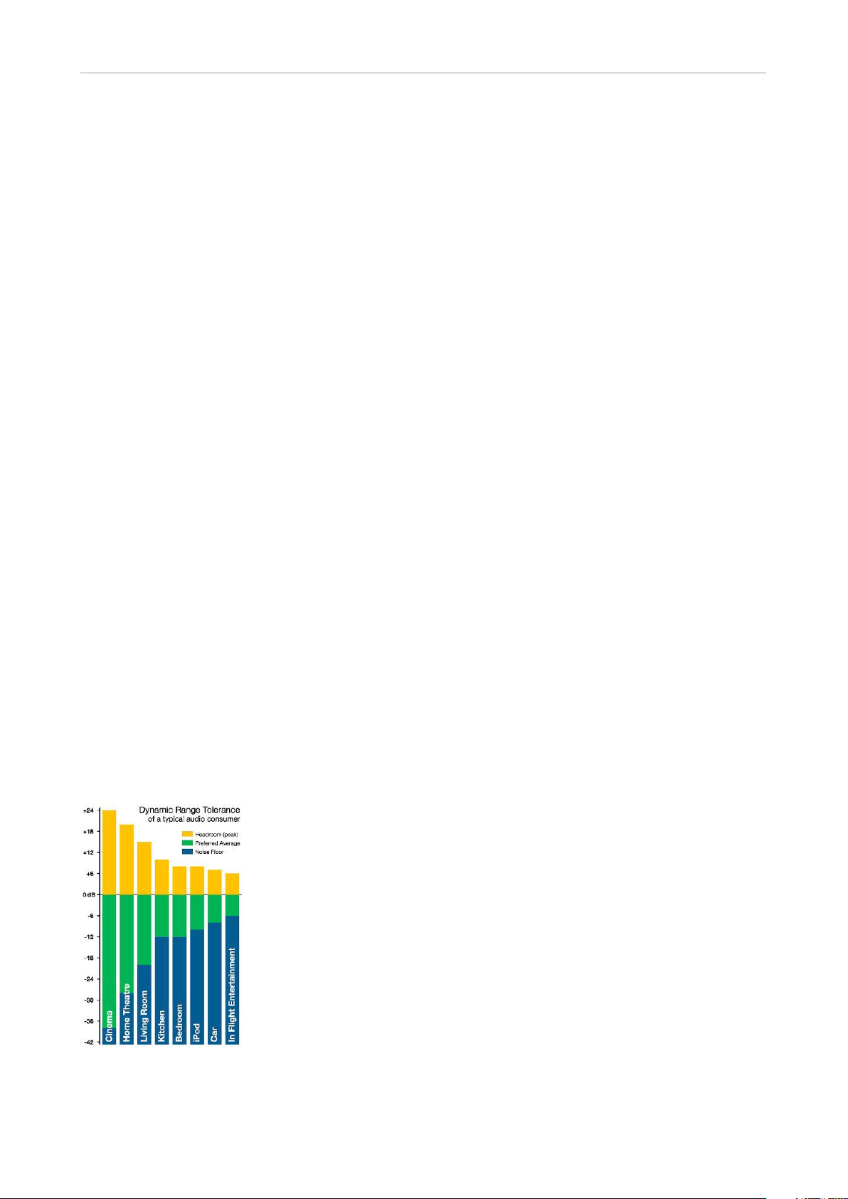
Dynamic range tolerance
(DRT) at the consumer
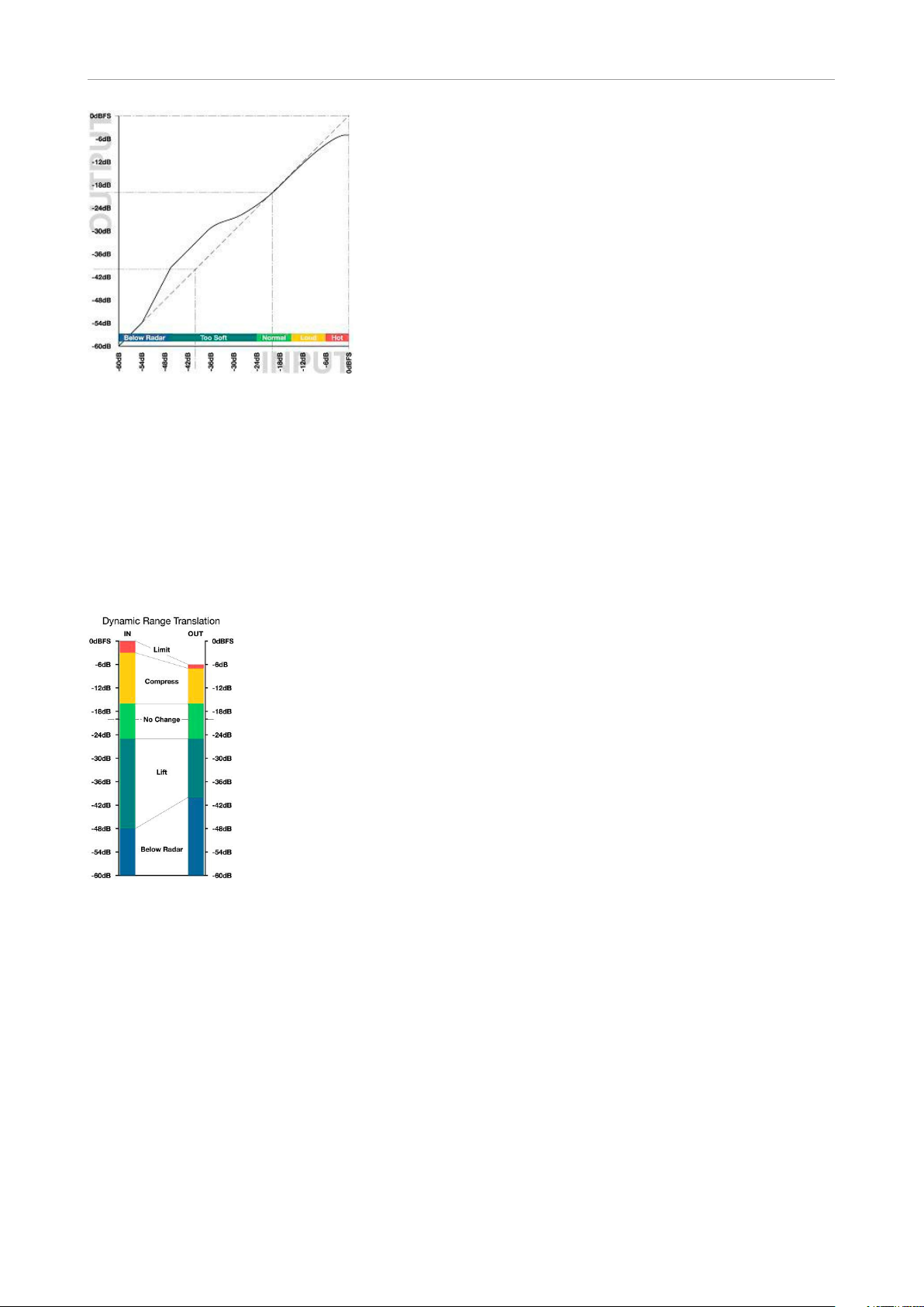
The Dynamic Range Tolerance map, Fig 1, illustrates the dynamic range targets for various
listening environments. It is therefore a practical tool for optimizing listener pleasure in digital
broadcast.
According to recent studies, listeners typically
object against too wide dynamic range much
more than when the range is too restricted. Lack
of speech intelligibility is the second worst offender, and often the cause for requesting more
dynamic range limitation. Against the hopes of
audio aficionados, as more people are listening
through headphones (iPods and other personal
entertainment systems), the DRT trend is therefore currently moving towards more dynamic
range restriction in broadcast.
Broadcast Material
Today, program material for TV broadcast is generally aimed at a listener in the Living Room or
Kitchen region, see Fig 1. This kind of material
should be thought of as having a normal broadcast dynamic range signature.
Commercials, promos and consumer CDs typically have a more restricted dynamic range, and
therefore appear loud on TV, where normalization is based only on peak content. This kind of
material should be thought of as having a hot
dynamic range signature.
On the opposite side we have film production,
aimed at a completely different listening scenario, where much softer and much louder level
than the average can be reproduced and heard.
Production for wide dynamic range listening can
also include classical or acoustic music. All material of such nature should be thought of as having a soft dynamic range signature.
Music and entertainment radio is typically aimed
at Car listening, so the dynamic range signature
is generally hot. The only type of radio with a
wider dynamic range typically carries classical
music, drama and low key, talk based programming.
To summarize, broadcast material is produced in
a way that fits the listening conditions of a wide
majority of consumers in the best possible way.
The most dramatic difference between program
material and consumer requirements concerns
feature film. To have a feature film align with domestic listening conditions without loosing too
much detail, or distorting the loud parts, low level may need to be brought up by 12 to 20dB, and
the headroom restricted by 12 to 16dB.
Processing for digital broadcast
Digital broadcast has the potential to carry more
formats at a wider dynamic range than analog.
For example, feature films can be presented
more like they were mixed and edited, with fewer
compromises on the picture as well as on the
audio side. However, even for HDTV, audio still
needs optimization for a presentation environment different than a cinema, like the picture still
needs color space, rate and resolution correc-
Fig 1.
DRT map for consumers under different listening situations.
English Manual 7
tions.
Page 12
MDX 5.1
The jumping level problem from analog TV will
become bigger if stations transmit feature films
with a less suitable dynamic range than today,
because film fall way outside the Dynamic Range
Tolerance of the average consumer under her
domestic listening conditions.
Consequently, dynamic range restriction must
take place either at the station, or inside the consumer’s receiving device.
Dynamic range translation should deal with both
overly soft and overly loud parts. Ideally, the perfect re-mapping should happen at the receiving
end to accommodate a wide range of listening
conditions. Metadata in conjunction with, for instance, Dolby AC3, provides some of these capabilities. However, even if the consumer knows
how to adjust the dynamic range of a film to her
current listening conditions, the optimum dynamics treatment unfortunately far exceeds the
capabilities of an AC3 decoder. The dynamic
range control in the codec is acceptable for cut
and boost ranges of 4 to 6dB, but preparing a
feature film for broadcast needs considerably
more than this.
If such a large correction is left only to the
AC3decoder, the wide-band gain changes can
be quite audible. Film and music dynamic range
correction requires a multiband structure so listeners don’t sacrifice speech intelligibility, or get
subjected to the spectral intermodulation of a
crude, wideband range controller.
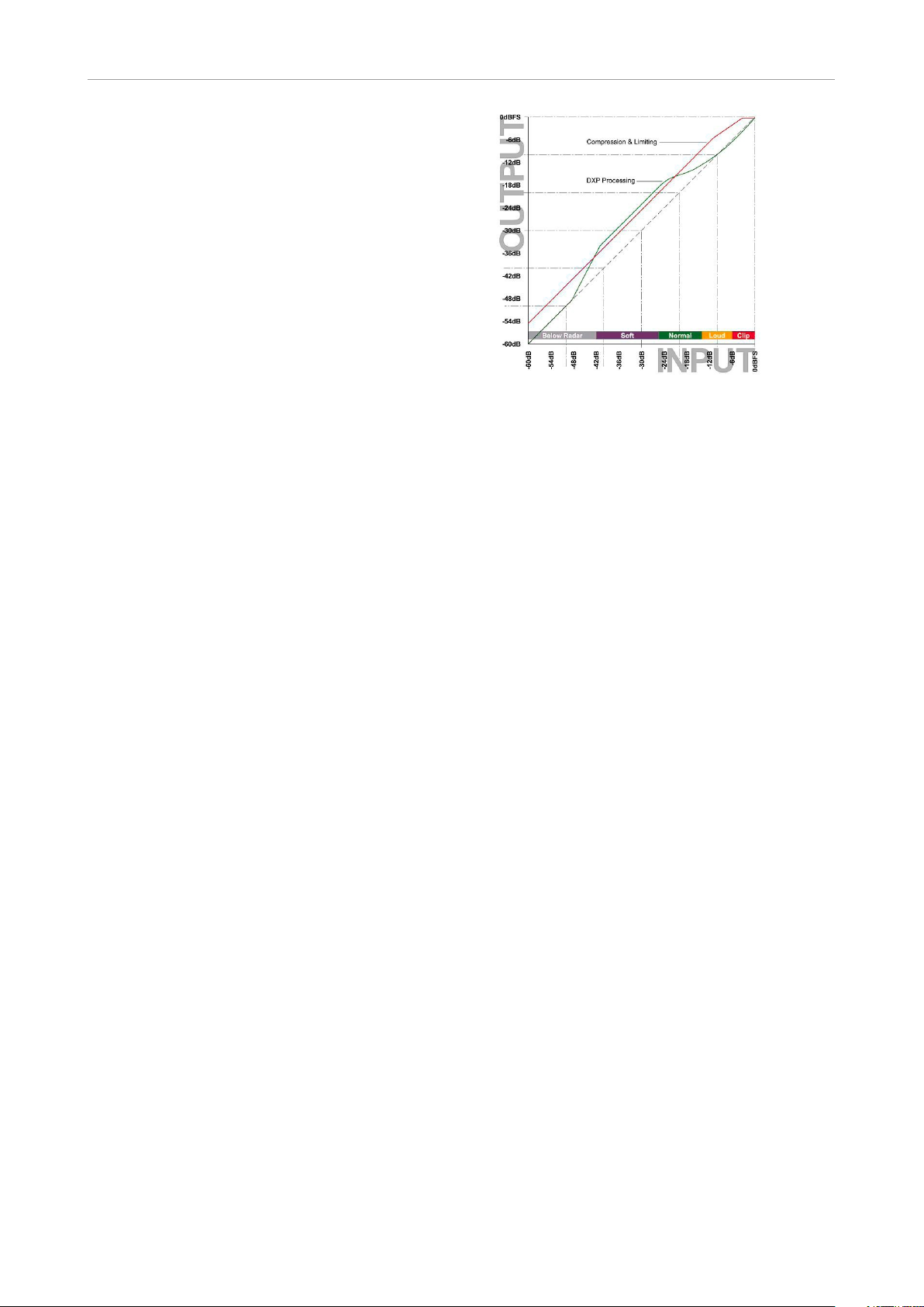
MDX 5.1
The MDX 5.1 processor available in DB4 and
DB8 is capable of bringing up low level detail,
rather than boosting everything, and then having
to limit the transients afterwards, see Fig 2. Low
level lift can even be applied to specific channels
selectively in one, two or three frequency bands.
Fig 2.
DXP processing vs. traditional Compression
and Limiting. Note how already loud signals are
unnecessarily affected when relying on limiting
and clipping.
Applications
MDX5.1 is well suited for dynamic range control
of any kind of broadcast material. Film, sports,
music or game shows. It may be applied during
ingest, transmission – or both places.
With suitable parameter settings, high resolution audio can pass through more than one hundred MDX 5.1 processors without perceivable
degradation of quality The ingenious topology
of DB4 and DB8 allows for the processing to
be performed instantly (the latency is below 0.5
ms, equivalent to moving a microphone approximately 16 cm or 6 inches), making re-alignment
of audio and picture a non-issue.
Processing strategies
The major part of dynamic range translation
should be done at the station, leaving only smaller corrections to be performed at the consumer.
This ensures competitive audio with regards to
consistency, quality and speech intelligibility,
and prevents asking more from the AC3decoder
than it can deliver in a civilized manner.
8 DB4 / DB8 MKII Algorithm s
Page 13
MDX 5.1
Tip: Use the Input Gains as overload protected
level trims in a critical realtime system, such as
broadcast, OB or live music.
On the Link pages, the 5 Main channels (L, C, R,
SL and SR) can be linked in numerous ways. The
concept is to assign a channel to a Sidechain. If
all channels are assigned to the same Sidechain,
processing is identical on all of them. If a channel
is assigned to a different Sidechain, processing
on that channel may be different from processing on the other channels.
The DXP pages reveal separate controls for
Sidechain 1 to 3 plus LFE. This enables, for in-
Fig 3.
Example of dynamic range re-mapping: From
Home Theatre/DVD to Living Room listening
conditions (Fig 1).
stance, different settings for the Center or Surround channels, where speech intelligibility or
low level ambience tend to get lost. Like when a
feature film is re-purposed for broadcast or DVD
under domestic listening conditions.
Fig 3 and Fig 4 show rational transfer characteristics complying with the DRT of the consumer,
without affecting levels when they are already
on target.
If it is required to process more audio channels
than 5.1, Engines can be run in parallel to cater
for 6.1, 7.1, 10.2, 12.2 or even higher number for-
mats. Parallel Engines attain perfect phase con-
servation and resolution, and do not compro-
mise audio in any way.
Fig 4.
Example of dynamic range re-mapping: From
Home Theatre/DVD to Living Room listening
conditions (Fig 1).
Basic Operation
On the Main page, MDX 5.1 offer Input Gain
controls for the Main Channels and for the LFE
Channel. This enables positive and negative gain
normalization to be performed in the 48 bit domain prior to low level processing and output
limiting. These gain controls therefore operate in
a safe location, well protected from generating
output overloads.
MDX 5.1 features 48 bit fixed point processing
throughout. Split and reconstruction filters are
phase linear when the algorithm is used in mul-
tiband modes.
English Manual 9
Page 14
MDX 5.1
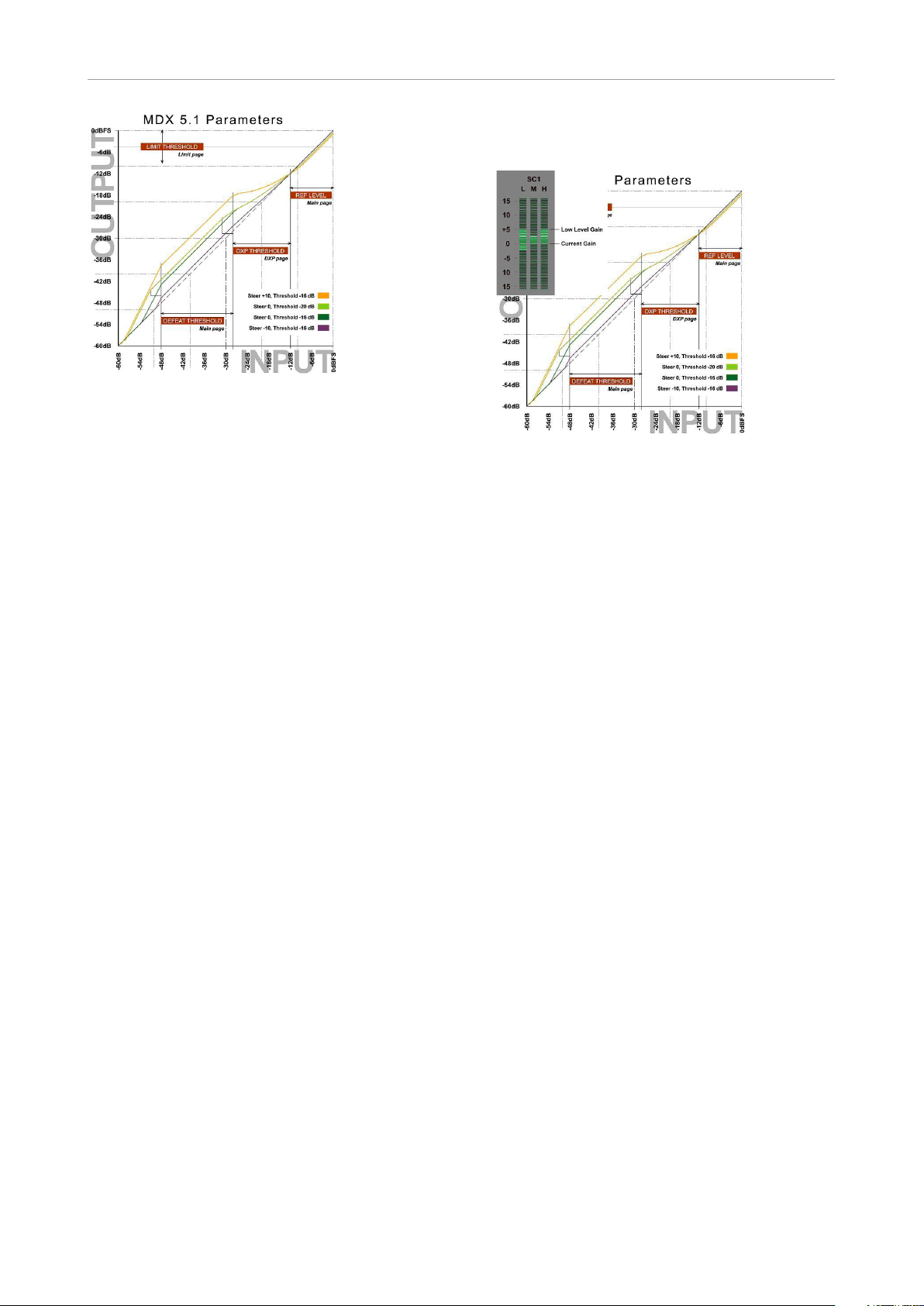
Fig 5.
MDX5.1 Level Diagram for different Steer and
Threshold settings.
“Defeat Threshold” relates to DXP Threshold
which relates to “Ref Level”. “Limit Threshold”
only relates to Digital Full Scale output level.
The Ref Level parameter on the Main page sets
the unity gain point for all channels (unless gain
offsets are applied), see Fig 5.
The Thresholds on the DXP pages are relative
to Ref Level, so in this particular drawing, Ref
Level is set at -12dBFS, while most DXP Thresholds are set at -16 dB. If you invoke the Defeat
Threshold, gain reverts to unity for “below radar”
input levels. Defeat Threshold is relative to DXP
Threshold. In the drawing, the Defeat Threshold
is set at -20dB.
Note, that the lower the DXP Threshold, or the
higher a Steer setting, the more low level boost
is applied. The low level boost can be different
in different channels, and even in different frequency bands.
Also observe that the Limiter threshold setting is
not relative to Ref Level, but always referenced
to output full scale.
frequency band is currently attenuated by 2dB,
while the Mid and Hi bands are at 0dB gain.
Fig 6.
Example of MDX5.1 Gain Meter. The me-
ter shows max low level gain and spectral re-
sponse, plus current gain and spectral re-
sponse. In the example, the Low band is cur-
rently attenuated by 2dB, while Mid and Hi
bands are at unity gain (0dB).
Adjustment Tips
The easiest way to specify the yellow area of Fig
1 is to set an appropriate difference between the
Ref Level parameter and the Limit Threshold.
Wide dynamic range material for a high reso-
lution delivery might be broadcast with a sub-
stantial difference between the two, for instance
15dB or more.
If the audio bandwidth is low, and the listener
environment presumably noisy, the difference
between Reference and Limit Thresholds should
smaller. For heavily data reduced multi-channel
broadcast, best results are typically obtained
with a 6 to 10dB difference.
When significant data reduction is to be used,
Reading the Gain Meters
Gain meters in indicate absolute gain. The upper
segments of a meter gives an indication of the
boost and frequency response applied to low
level signals, while the lower segments of a meter gives an indication of the current (dynamic)
gain and frequency response, see Fig 6.
In this example, low level signals are subject to
a 5dB boost in the Low and Hi band. The Low
10 DB4 / DB8 MKII Algorithm s
also be careful not to allow peaks going all the
way to 0dBFS. Consider bringing down the Limit
Threshold between 1 and 4dB. Judge the qual-
ity of loud, spacious material passing through
MDX 5.1 plus data reduction plus decoding,
while listening to the output of the data reduc-
tion decoder. Pay special attention to transient
distortion, and if the sound image collapses at
high levels.
Page 15
MDX 5.1
In general, and especially for feature film remapping in ingest, start by processing all channels by the same amount. This can be achieved
by assigning all channels to Sidechain 1, or by
using different sidechains with identical settings.
Then conclude if speech in the center channel,
ambience in the surrounds or activity in the LFE
channel etc. needs special attention and processing.
When it is indicated to bring up dialog level and
speech intelligibility, you may end up with something like the level diagram presented in Fig 5.
This particular transfer curve has been used
successfully at stations with special attention to
speech intelligibility.
Compare against the DRT chart, fig 1, and note
how the Center channel is given an extra low level advantage compared to the four lateral channels, without the basic mix balance being generally changed. This curve ensures that dialog can
still be heard when the words could otherwise be
lost to listening room noise. The lateral channels
are linked two and two, or all in one group. Presets of this nature is located in Engine Factory
Bank F2 (“Loudness, Multichannel”), decade 3,
preset 0 to 3 (“Film Curve C3 – C12”).
Tip: To produce multiple ingest versions from the
same source material, start doing the one for the
highest resolution.
Lower resolution versions can be achieved by
adjusting the Limit Threshold to comply with the
alternative delivery format, then adjusting the Ref
Level to optimize results under the new, restrict-
ed dynamic range conditions. In many cases, no
further tweaking will be needed.
Please be advised that some reproduction sys-
tems distort when downmixing hot multichannel
signals to stereo. Therefore, don’t abuse multi-
channel formats by bringing all channels close to
0dBFS at the same time, except for short dura-
tion, loud incidents.
Tip: When making the final transmission adjust-
ments, try changing the Ref Level parameter up
and down a few dB. This is an efficient way of
trimming hundreds of parameters in MDX5.1 at
the same time. Listen to the result, while decid-
ing what is the optimum setting for that particular
broadcast platform.
MDX5.1 Factory Preset
Nomenclature
Engine presets based on the MDX5.1 algorithm
is located in Factory Bank F2 (“Loudness, Multi-
channel”), decade 2 and 3. Presets are labelled
Film Curve A-D plus a number.
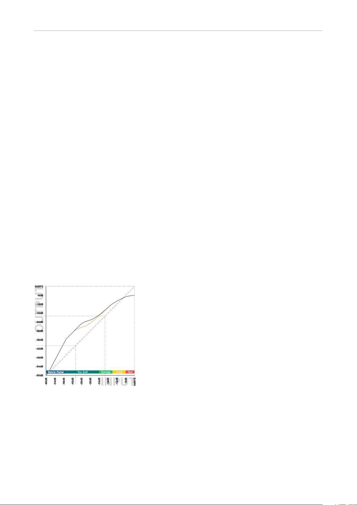
Fig 7.
Example of multiband dynamic range re-mapping of a 5.1 feature film to domestic listening
conditions.
Preset names: “Film Curve C3-C12”.
Black curve: Center channel.
Orange curve: L, R, Ls, Rs.
Film Curve A presets add the same amount of
boost to all 5.1 channels. At Reference Level, the
gain is unity (0 dB). At low level (- 35dBFS and
below), the number after the “A” in the preset title
indicates the amount of low level boost. For ex-
ample, the preset “Film Curve A6” adds 6dB of
low level gain to all 5.1 channels.
Film Curve C presets add the same amount of
boost to all 5.1 channels, but the max gain is
achieved earlier for the Center channel than for
the rest (like in Fig 5). At Reference Level, the
gain is unity (0 dB). At low level (- 35dBFS and
below), the number after the “C” in the preset
title indicates the amount of low level boost. For
example, the preset “Film Curve C6” adds 6dB
of low level gain to all 5.1 channels.
Film Curve D presets add 3dB more gain to the
Center channel than to the other channels. Max
gain is also achieved earlier for the Center chan-
nel than for the rest (like in Fig 5). At Reference
English Manual 11
Page 16
MDX 5.1
Level, the gain is +3dB for the Center channel,
but unity (0 dB) for the others. At low level (35dBFS and below), the number after the “D” in
the preset title indicates the amount of low level
boost. For example, the preset “Film Curve D6”
adds 9dB of low level gain to the Center channel, but 6dB of low level gain to the rest of the
channels.
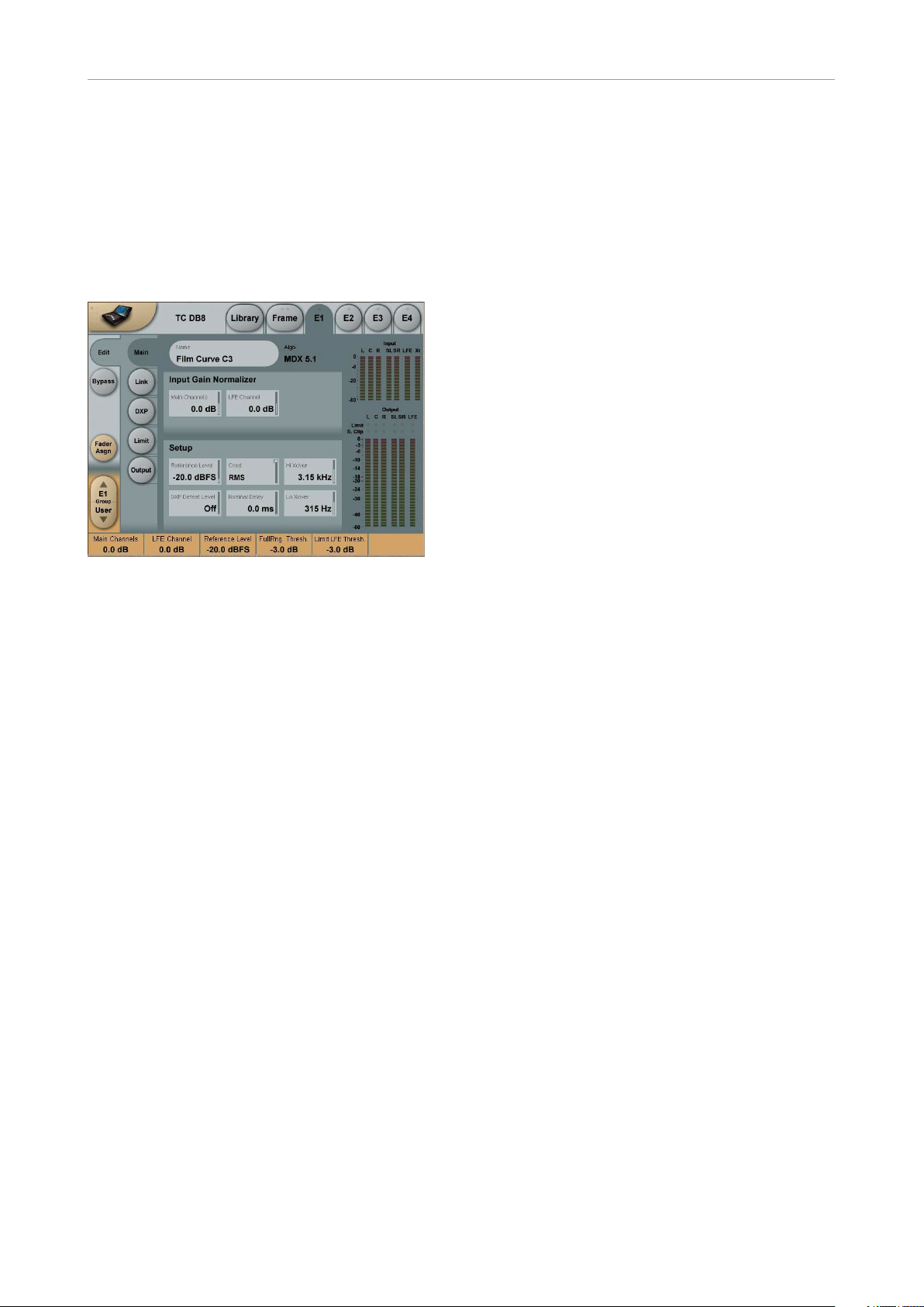
MDX5.1 algorithm – main page
The dB steps between RMS and Peak are the
dBs needed for a peak-value to override RMS
measurement.
DXP Defeat Level
Range: Off, -30dB to -3dB
MDX 5.1 may remove low level gain below the
threshold set with this parameter to avoid having
irrelevant sources (e.g. background noise) be-
come audible. Low level gain is not revoked if the
DXP Defeat Level parameter is set to Off.
The Defeat threshold is relative to DXP Band
Thresholds, which are relative to Reference Lev-
el.
Example: If Reference Level is set at -20dBFS,
Band Thresholds at -15 dB, and DXP Defeat
at -22 dB, low level boost starts rolling off at
-47dBFS. See example at page 18.
MDX5.1 algorithm – main page
Input Gain Normalizer for
Main and LFE channels
Range: -18dB to +18dB
As we process in a 48 bit domain both positive
and negative gain normalization can be performed prior to low level processing and output
limiting. These gain controls therefore operate in
a safe location, well protected from generating
output overloads.
Reference Level
Range: -24dBFS to 0dBFS in 0.5dB steps
This parameter sets the reference level in the algorithm. The reference level is the level at which
the Threshold parameters will start operating
when set to 0dB. E.g. if the Reference Level is
set to -18 dBFS (often referred to as 0 dBu), a
Threshold setting at -4dB, will cause the Compressor to start operating at -22dBFS.
Crest
Range:
Peak, 6dB, 10dB, 12dB, 14dB,
16dB, 20dB, 24dB, RMS
Select compression method between RMS and
PEAK.
Nominal Delay
Range: 0 to 15 ms
0 to 2 ms in 0.1 ms steps
2 ms to 15 ms in 0.5 ms steps
Adds a delay to the passing audio in order to
have regulation start “ahead of time”. Using this
control can reduce the need for peak limiting,
and prevent dynamic distortion from being add-
ed to sensitive material.
Note that look-ahead is scaled with Attack per
band.
Example: If a 5 ms Nominal Delay has been set,
and Attack is 10 ms on the low band and 1 ms
on the high band, audio is delayed 5 ms on all
bands (phase linear topology). However, to pre-
vent pre-transient holes from being generated,
Attack regulation starts 5 ms “ahead of time” on
the low band, but only a little more than 1 ms
“ahead of time” on the high band.
Hi/Lo Crossovers
MDX5.1 uses a phase linear, 48 bit split and re-
combination filter structure in order to enable dif-
ferent low level detail boost at different frequen-
cies. This counteracts spectral inter-modulation,
and is useful in order to preserve speech intel-
ligibility. Two-band or wide-band DXP process-
ing can be accomplished by setting one or both
crossover points to Off.
12 DB4 / DB8 MKII Algorith ms
Page 17
MDX 5.1
MDX5.1 algorithm –
link control page
MDX5.1 algorithm – link control page
The Sidechain assignment possibilities in the
MDX5.1 are very comprehensive. Carefully selecting which channels should be controlled by
which Sidechains, is just as essential as dialing
in the correct Threshold and Ratio values.
keeping the channel time-aligned to the other
(processed) channels.
Sidechain Control
Range – for the five main channels:
– Unprocessed
– Side Chain 1
– Side Chain 2
– Side Chain 3
Range – for the LFE channel:
– Unprocessed
– LFE
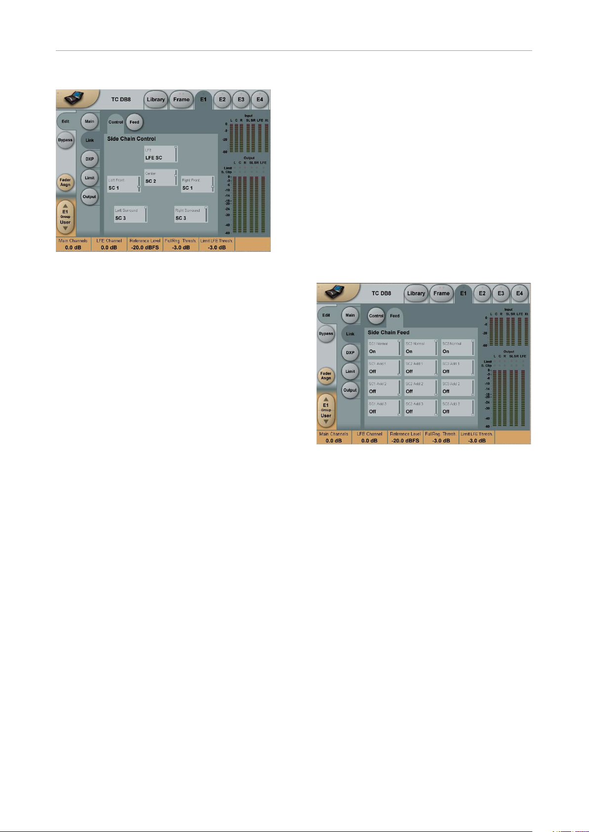
MDX5.1 algorithm – link feed page
It is possible to freely select any or none of three
Sidechains to control each of the main-channels.
This also gives you the option of grouping the
channels. In addition to this, the LFE channel
has its own Sidechain control. This enables e.g.
setting up two Multiband 5.1 algorithms in serial setup, while having six individual Sidechains
available, enabling fully individual Sidechain controls of all channels.
At the Feed page it is possible to make additional
Sidechain link Inputs, for e.g. having the Centerchannel contributing to the Sidechain Inputs of
the two Front channels, to create a more coherent sound from the front-channels.
The illustration above reflects the Processing parameter set to MDX5.1 in Normal mode.
Basic operation
At the Setup/Control page it is possible to decide
which Sidechains should control which channels. Select any of three Sidechains to be assigned to any of the five Main-channels. You can
also chose to pass the channels unprocessed
through the algorithm. The LFE channel can be
assigned to its own separate Sidechain, or be
left unprocessed.
Setting a channel to unprocessed will preserve
the processing delay through the algorithm,
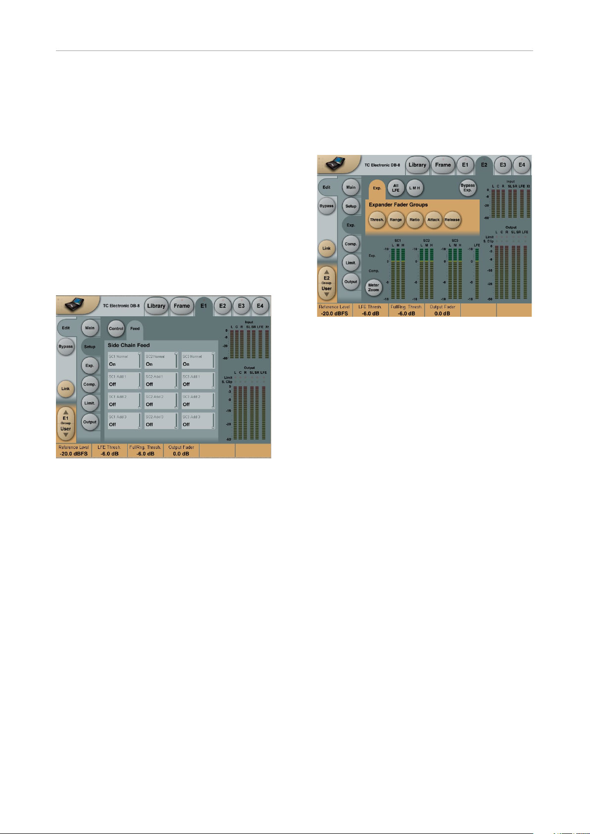
MDX5.1 algorithm – link feed page
The Setup/SC Feed page holds parameters
specifying which Input channels should feed the
three Sidechains.
Normal
Range: Off, On
When this parameter is set to “On” the Input
channels selected to be controlled by the re-
spective sidechain will also input to the side-
chain.
Add 1, Add 2 and Add 3
Range: Off, LFr Max, RFr Max, Cnt Max, LSr
Max, RSr Max, Xt Max, LFr Sum, RFr Sum,
Cnt Sum, LSr Sum, RSr Sum, Xt Sum.
These parameters enable extra channels to be
assigned to the respective Sidechain Input. The
extra sidechain Input channels will not be pro-
cessed by the sidechain.
English Manual 13
Page 18
MDX 5.1
The Sum settings will add the Input to the sidechain, whereas the Max settings only will contribute to the sidechain if the level exceeds the
other Input channel levels.
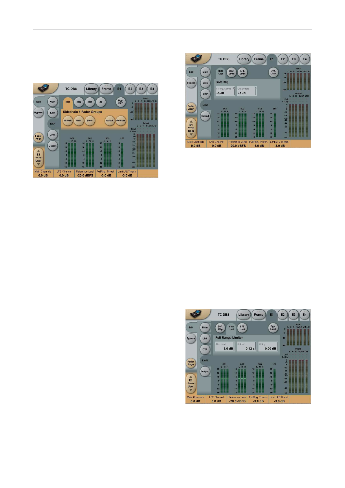
MDX5.1 algorithm – DXP page
MDX5.1 algorithm – DXP page
Sidechain Fader Groups
The DXP pages reveal separate controls for
Sidechain 1 to 3 plus LFE. This allows for different settings for the Center or Surround channels,
where speech intelligibility or low level ambience
tend to get lost, like when a feature film is repurposed for broadcast or DVD under domestic
listening conditions.
If it is required to process more audio channels
than 5.1, Engines can be run in parallel to cater
for 6.1, 7.1, 10.2, 12.2 or even higher number formats. Parallel Engines attain perfect phase conservation and resolution, and do not compromise audio in any way.
MDX5.1 algorithm – Limiter – soft clip page
Softclip
Full Range Softclip
Range: -6dB to Off
Softclipper Threshold setting after the Compres-
sor for the five multiband channels. Threshold
is always relative to 0dBFS (Not the Reference
Level).
LFE Softclip
Range: -6dB to Off
Softclipper Threshold setting for the LFE chan-
ne l only.
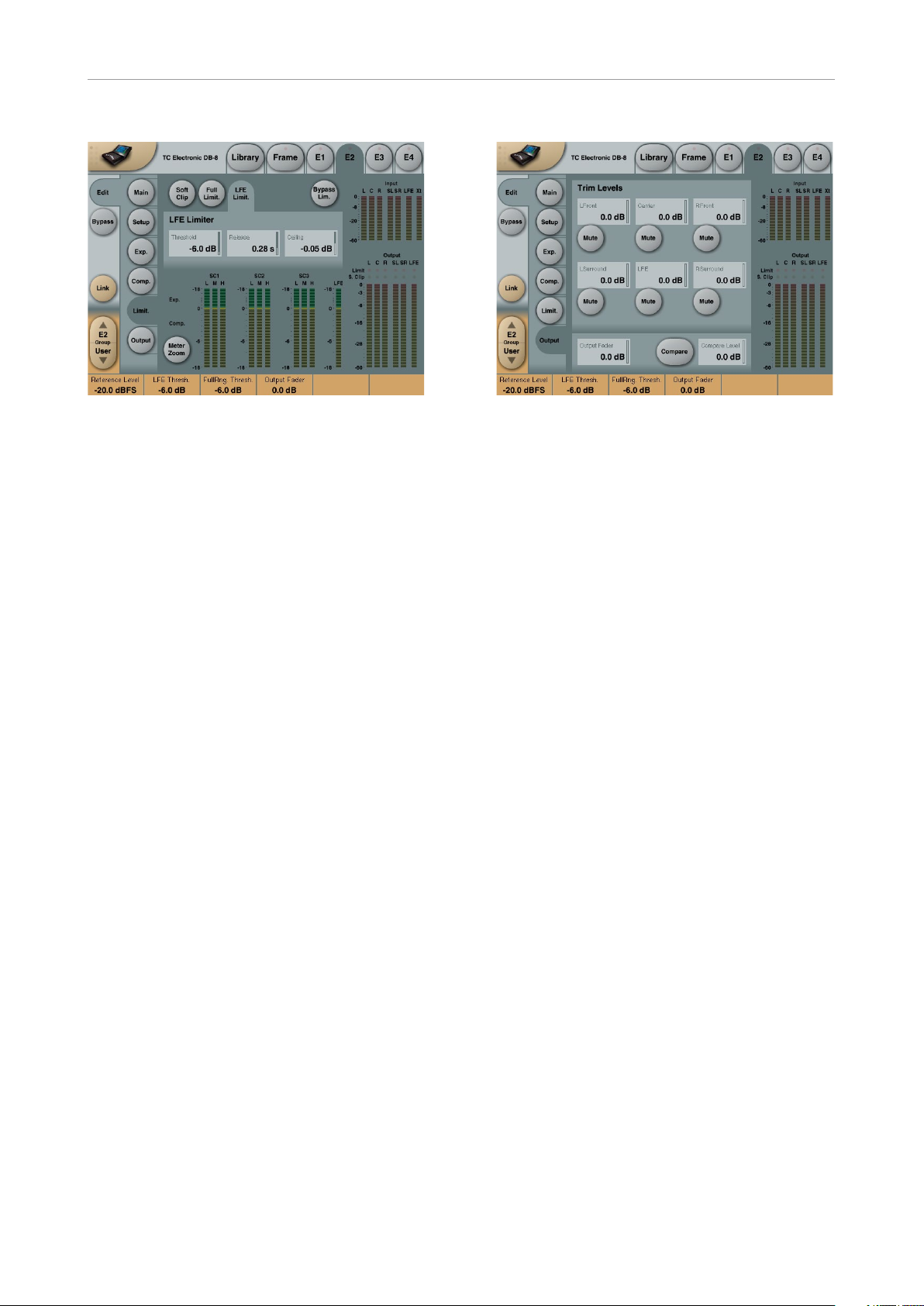
MDX5.1 algorithm –
Limiter – main page
MDX5.1 algorithm –
Limiter – soft clip page
The Limiter page is divided into three Sub-pages. One covering the Softclip section, one Main
Limiter and one for the LFE Limiter.
Generic parameters in this algorithm:
Meter Zoom
Press Meter Zoom to decrease meter range and
have a more accurate metering.
Bypass Limiter
Press to Bypass the Limiter section.
14 DB4 / DB 8 MKII Algori thms
MDX5.1 algorithm – Limiter – main page
Page 19

MDX 5.1
Threshold
Range: -12dB to Off
-6 to 0dB in 0.1dB increments
-12 to -6 in 0.5dB increments
Brickwall limiter for the five channels. Threshold
is always relative to 0dBFS. LED on each Output
meter indicates when Limiter is active.
Release
Range: 0.01 to 1.00 seconds
Release time for the Limiter.
Ceiling
Range: -0.10dB to 0dB
Fine-tuning parameter setting the Ceiling for the
Limite r.
The Ceiling parameter prevents the Output signal from exceeding the adjusted Limiter Threshold. It can be used to “hide” overloads to downstream equipment, but it does not remove the
distortion associated with an overload.
LFE Limiter
Threshold
Range:
-12 to +3dB
-6 to + 3 in 0.1dB increments
-12 to -6 in 0.5dB increments
Brickwall limiter for the LFE channel. Threshold
is always relative to 0dBFS. LED on each Output
meter indicates when the Limiter is active.
Release
Range: 0.01 to 1.00 seconds
Release time for the Limiter.
Ceiling
Range: 0 to -0.10dB in 0.01dB steps.
Fine-tuning parameter setting the Ceiling for the
Limite r.
The Ceiling parameter prevents the Output signal from exceeding the adjusted Limiter Threshold. It can be used to “hide” overloads to downstream equipment, but it does not remove the
distortion associated with an overload.
English Manual 15
Page 20

MDX 5.1
16 DB4 / DB8 MKII Algorithm s
Page 21
Mul t i b and 5 .1
Multiband5.1 algorithm
Multiband5.1
The inputs and outputs of this algorithm are distributed as follows:
Input Output
L
R R
C C
LFE LFE
SL SL
SR SR
E1
E2
E3
E4
L
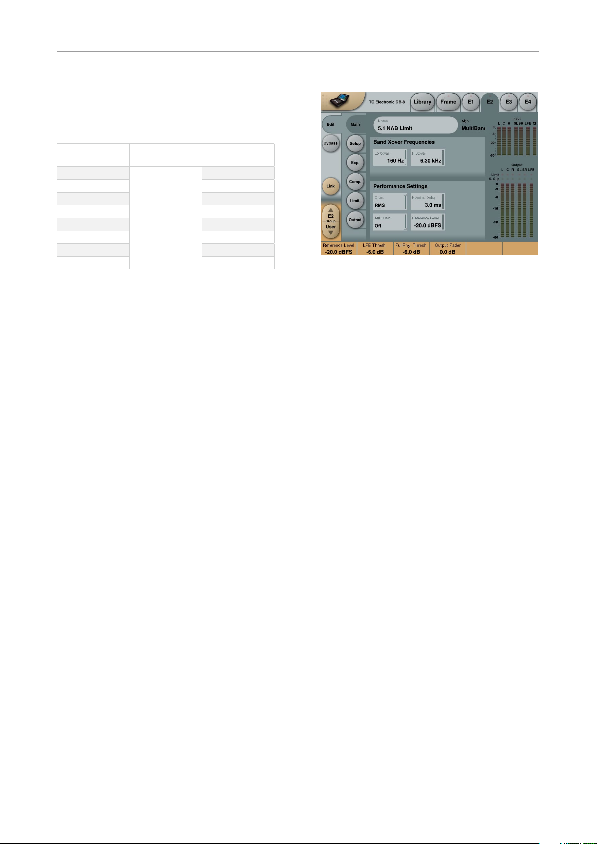
– main page
Multiband5.1 algorithm – main page
Introduction
The Multiband 5.1 algorithm is a multi-channel,
multi-band optimizer, with Limiters and extensive possibilities to assign channels to multiple
sidechains.
Four-band dynamics are available for 5.1 processing.
At the Main page, you have access to the general
set-up parameters for the Expander and Com-
pressor sections.
Meters are shown for all seven Inputs and six
Outputs at the right of the display.
With the Multiband5.1 it is possible to integrate
dynamics processing for 5.1 applications offering features, which are not possible if using multiple stereo dynamic processors.
Multiband5.1 processor contains:
– 5 channels of three band expansion and com-
pression
– Full-range brickwall limiter on all Outputs
– 1 channel of full range expansion, compres-
sion and limiting for the LFE (Sub) channel
– 3 Sidechains for the five main channels, that
can be assigned in flexible ways
– 1 extra Input channel that can be used for ex-
ternal Side Chain Input.
Band Xover Frequencies
Lo Xover
Range: Off to 16 kHz
Sets the Cross-over frequency between the Loand the Mid- Expander and Compressor bands
for the five main channels (LFr, RFr, Cnt, LSr,
RSr).
The two Cross-over points are not allowed to
cross each other. Therefore the parameter range
can be less than 16 kHz if the Hi Xover parameter
is set below 16 kHz.
Hi Xover
Range: Off to 16 kHz
Sets the Cross-over frequency between the Midand the Hi- Expander and Compressor bands for
the five main channels (LFr, RFr, Cnt, LSr, RSr).
The two cross-over points are not allowed to
cross each other. Therefore the parameter range
can be less than going down to Off, if the Lo
Xover parameter is set above the Off position.
English Manual 17
Page 22
Mul t i b and 5 .1
Performance Settings
Crest
Range:
Peak, 6dB, 10dB, 12dB, 14dB, 16dB, 20dB,
24dB, RMS
Select compression method between RMS and
PEAK.
The dB steps between RMS and Peak are the
dBs needed for a peak-value to override RMS
measurement.
Nominal Delay
Range: 0 to 15 ms
(<2 ms in 0.1 ms steps. >2 ms in 0.5 ms steps)
Sets the nominal Delay of the signal compared
to the
Sidechain signal. This is also known as “Look
ahead Delay”, enabling the Compressor section to become more responsive to the incoming signal.
Automatic Make Up Gain
Range: Off/On
Switches the Automatic Make-up gain On or Off.
As using compression is a reduction of dynamic
range in the signal a compensation for this loss
of gain on the Output side is possible. Use the
Auto Make Up gain to achieve this.
Reference Level
Range: -24dBFS to 0dBFS in 0.5dB steps
This parameter sets the reference level in the algorithm. The reference level is the level at which
the Threshold parameters will start operating
when set to 0dB. E.g. if the Reference Level is
set to -18 dBFS (often referred to as 0 dBu), a
Threshold setting at -4dB, will cause the Compressor to start operating at -22dBFS.
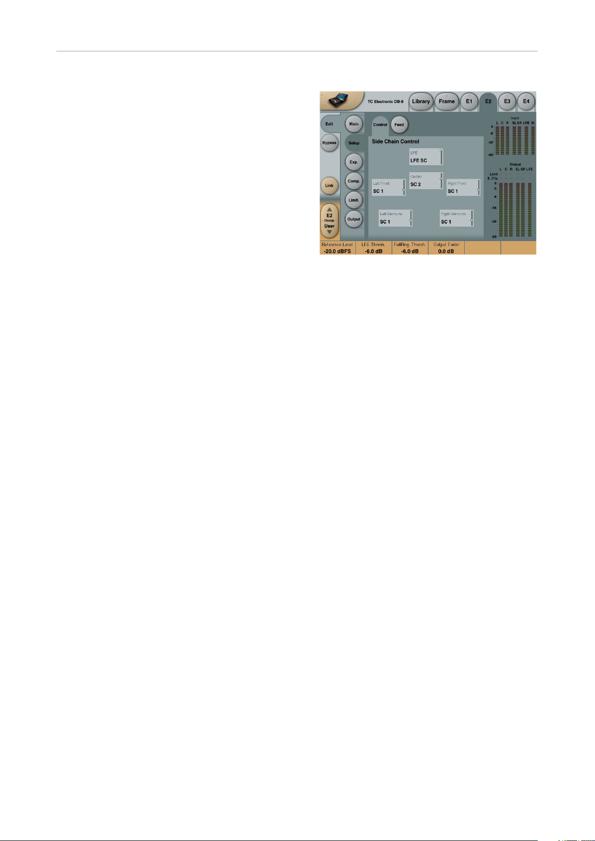
Multiband5.1 algorithm –
side chain control page
Multiband5.1 algorithm – side chain control
page
The sidechain assignment possibilities in the
Multiband5.1 are very comprehensive. Carefully
selecting which channels should be controlled
by which Sidechains, is just as essential as dialing in the correct Threshold and Ratio values.
It is possible to freely select any or none of three
Sidechains to control each of the main-channels.
This also gives you the option of grouping the
channels. In addition to this, the LFE channel
has its own Sidechain control. This enables e.g.
setting up two Multiband 5.1 algorithms in serial setup, while having six individual Sidechains
available, enabling fully individual Sidechain controls of all channels.
At the Feed page it is possible to make additional
Sidechain link Inputs, for e.g. having the Centerchannel contributing to the Sidechain Inputs of
the two Front channels, to create a more coherent sound from the front-channels.
The illustration above reflects the Processing
parameter set to Multiband5.1 in Normal mode.
Basic operation
At the Setup/Control page it is possible to decide
which Sidechains should control which channels. Select any of three Sidechains to be assigned to any of the five Main-channels. You can
also chose to pass the channels unprocessed
through the algorithm. The LFE channel can be
assigned to its own separate Sidechain, or left
unprocessed.
18 DB4 / DB8 MKII Algorith ms
Page 23
Mul t i b and 5 .1
Setting a channel to unprocessed will preserve
the processing delay through the algorithm,
keeping the channel time-aligned to the other
(processed) channels.
Side Chain Control
Range – for the five main channels:
– Unprocessed
– Side Chain 1
– Side Chain 2
– Side Chain 3
Range – for the LFE channel:
– Unprocessed
– LFE
Multiband5.1 algorithm –
side chain feed page
The Sum settings will add the Input to the sidechain, whereas the Max settings only will contribute to the sidechain if the level exceeds the
other Input channel levels.
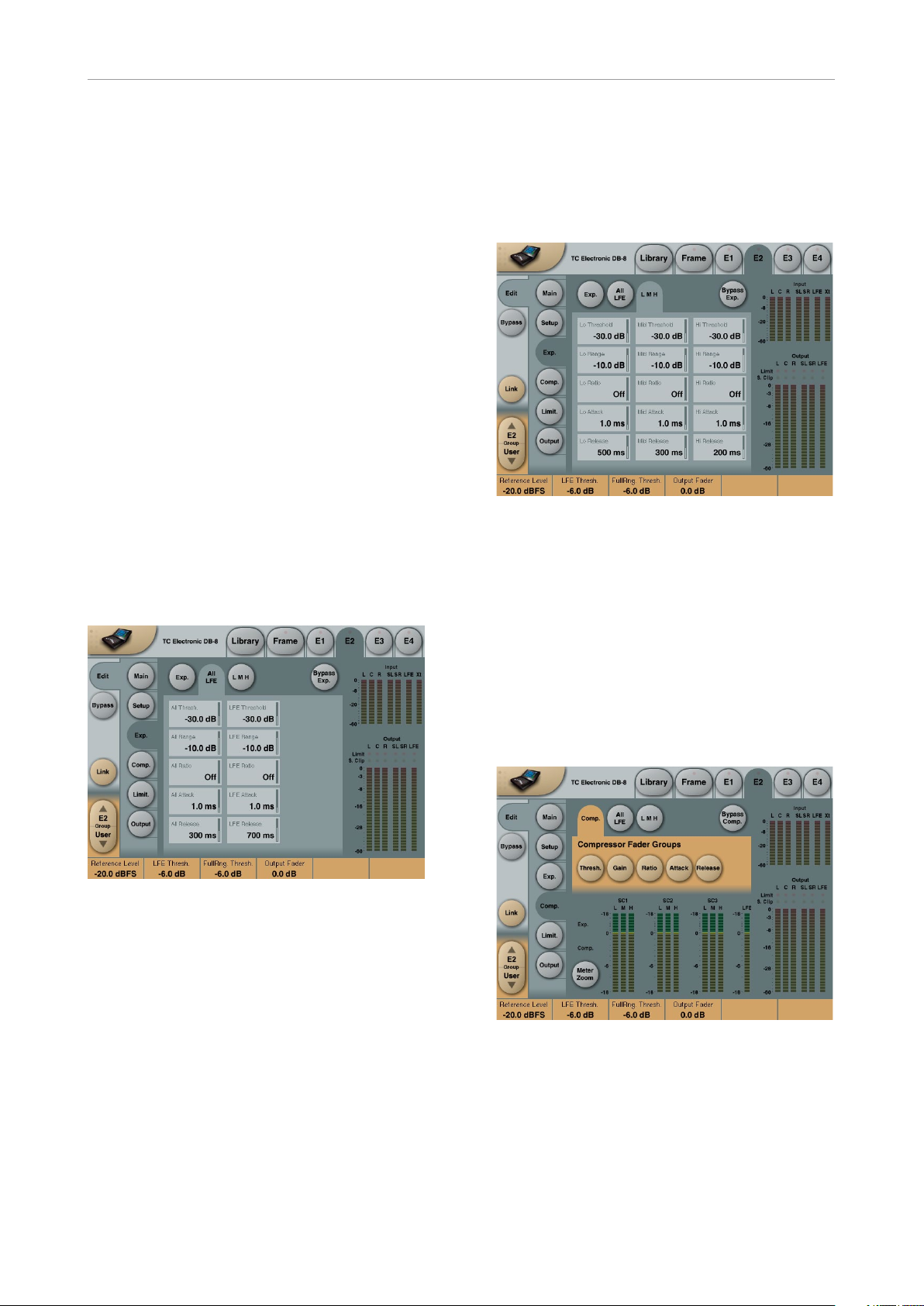
Multiband5.1 algorithm –
Expander – main page
Multiband5.1 algorithm – Expander – main
page
Multiband5.1 algorithm – side chain feed page
The side chain feed page Setup/SC Feed page
holds parameters specifying which Input channels should feed the three side chains.
Normal
Range: Off, On
When this parameter is set to “On” the Input
channels selected to be controlled by the respective sidechain will also Input to the sidechain.
Add 1, Add 2 and Add 3
Range:
Off, LFr Max, RFr Max, Cnt Max, LSr Max,
RSr Max, Xt Max, LFr Sum, RFr Sum, Cnt
Sum, LSr Sum, RSr Sum, Xt Sum.
These parameters enable extra channels to be
assigned to the respective Sidechain Input. The
extra Sidechain Input channels will not be processed by the sidechain.
Pressing Threshold, Range, Ratio, Attack and
Release keys will immediately assign Lo, Mid, Hi,
All and LFE values for these parameters to Faders 1 to 4.
Be aware that the range of the All parameter is
relative to the settings of the same parameters in
the Compressor section.
Threshold
Range: -50dB to 0dB (in 0.5dB steps)
When the signal drops below the set Threshold
point the Expander starts to generate downward
expansion.
Range
Range: -40dB to 0dB in 0.5dB steps
Sets the maximum range of the expansion.
Ratio
Range: Off to Infinity
Sets the Expansion Ratio below the Threshold
point.
English Manual 19
Page 24
Mul t i b and 5 .1
Release
Range: 20 ms to 7 sec.
Sets the time it takes for the Expander to release
its attenuation of the signal when the signal exceeds the Threshold again.
Attack
Range: 0.3 to 100 ms
Sets the time it takes for the Expander to reach
the attenuation specified by the Ratio parameter when the signal drops below the Threshold
point.
Meter Zoom
Press Zoom to decrease meter range and have a
more accurate metering.
Bypass Exp.
Press to bypass the Expander section of the MD
5.1 algorithm.
“LFE” parameters
These parameters are equivalent to the “LFE”
Threshold, Range, Ratio, Attack and Release
parameters.
Multiband5.1 algorithm –
Expander – L M H page
Multiband5.1 algorithm – Expander – L M H
page
Multiband5.1 algorithm –
Expander – All LFE page
Multiband5.1 algorithm – Expander – All LFE
page
Pressing any parameter will assign this to Fader
6.
Pressing any parameter will assign this to Fader
6.
This page holds all Expander Threshold, Range,
Ratio, Attack and Release parameters for the Lo,
Mid and Hi bands.
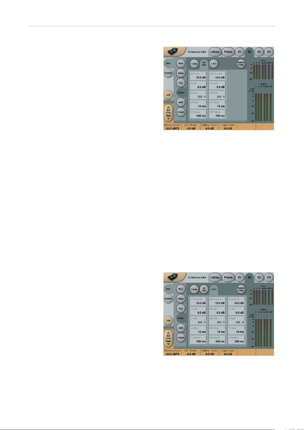
Multiband5.1 algorithm –
Compressor – main page
“All” parameters
These parameters are equivalent to the “All”
Threshold, Range, Ratio, Attack and Release
parameters.
20 DB4 / DB8 MKII Algor ithms
Multiband5.1 algorithm – Compressor – main
page
Pressing Threshold, Range, Ratio, Attack and
Release keys will immediately assign Lo, Mid,
Hi, All and LFE values for these parameters to
Faders 1 to 4. Be aware that the range of the All
parameter is relative to the settings of the same
parameters in the Expander section.
Page 25
Mul t i b and 5 .1
Threshold
Range: -25dB to 20dB (in 0.5dB steps)
Sets the Threshold level at which the Compressor starts to operate. The Threshold parameter
relates to the Reference Level setting.
Example: If the Reference Level is set to -18dBFS,
a Threshold setting of -4dB, will cause the compressor to start operating at -22dBFS.
Gain
Range: Off, -18dB to 12dB in 0.5dB steps.
Adjusts the gain after the Compressor.
If the Auto Make-up gain parameter is set to On
in the Main page, these gains will already have
been adjusted according to the Threshold and
Ratio parameters.
Ratio
Range: Off to Infinity
Sets the Compression Ratio that must be performed above the Threshold point.
Attack parameters
Range: 0.3 to 100 ms
Sets the time the Compressor takes to reach
the attenuation specified by the Ratio parameter
when the level exceeds the Threshold point.
Multiband5.1 algorithm –
Compressor – All LFE page
Multiband5.1 algorithm – Compressor – All LFE
page
Pressing any parameter will assign this to Fader
6.
“All” parameters
These parameters are equivalent to the “All” –
Threshold, Range, Ratio, Attack and Release
parameters.
“LFE” parameters
These parameters are equivalent to the “LFE”
– Threshold, Range, Ratio, Attack and Release
parameters.
Release parameters
Range: 20 ms to 7 sec.
Sets the time the Compressor takes to release
the attenuation of the signal when the signal level
drops below the Threshold point.
Meter Zoom
Press Meter Zoom to decrease meter range and
have a more accurate metering.
Multiband5.1 algorithm –
Compressor – All L M H page
Multiband5.1 algorithm – Compressor – All L M
H page
Pressing any parameter will assign this to Fader
6.
English Manual 21
Page 26
Mul t i b and 5 .1
This page holds all Compressor Threshold,
Range, Ratio, Attack and Release parameters for
the Lo, Mid and Hi bands.
Limiter
The Limiter page is divided into three Sub-pages. One covering the Softclip section, one for the
Full Range Limiter and one for the LFE Limiter.
Generic parameters in this algorithm:
Meter Zoom
Press Meter Zoom to decrease meter range and
have a more accurate metering.
Bypass Limiter
Press to Bypass the Limiter section of the 5.1
algorithm.
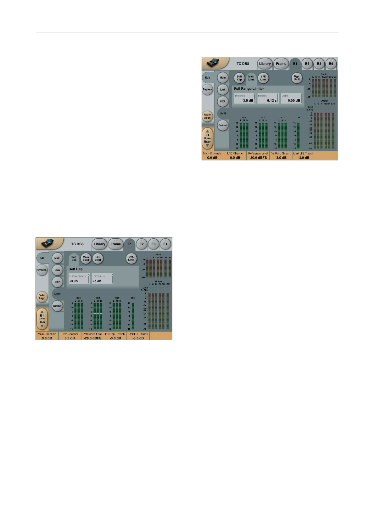
Multiband 5.1 algorithm
– soft clip page
Multiband5.1 algorithm
– full Limiter page
Multiband5.1 algorithm – full Limiter page
Threshold
Range:
-12dB to Off
-6 to 0dB in 0.1dB increments
-12 to -6 in 0.5dB increments
Brickwall limiter for the five multiband channels.
Threshold is always relative to 0 dBFS. LED on
each Output meter indicates when Limiter is active.
Multiband5.1 algorithm – soft clip page
Softclip
Full Range Softclip
Range: -6dB to Off
Softclipper Threshold setting after the Compressor for the five multiband channels. Threshold
is always relative to 0dBFS (Not the Reference
Level.
LFE Softclip
Range: -6dB to Off
Softclipper Threshold setting for the LFE channe l only.
Release
Range: 0.01 to 1.00 seconds
Release time for the Limiter.
Ceiling
Range: -0.10dB to 0dB
Fine-tuning parameter setting the Ceiling for the
Limite r.
The Ceiling parameter prevents the Output signal from exceeding the adjusted Limiter Threshold. It can be used to “hide” overloads to downstream equipment, but it does not remove the
distortion associated with an overload.
22 DB4 / DB8 MKII Algorithm s
Page 27
Mul t i b and 5 .1
Multiband5.1 algorithm
– LFE Limiter page
Multiband5.1 algorithm – LFE Limiter page
LFE Limiter
Threshold
Range:
-12 to +3dB
-6 to + 3 in 0.1dB increments
-12 to -6 in 0.5dB increments
Brickwall limiter for the LFE channel. Threshold
is always relative to 0dBFS. LED on each Output
meter indicates when limiter is active.
Multiband5.1 algorithm
– output page
Multiband5.1 algorithm
– output page
Trim Levels
Output trims
Range: 0dB to -12dB in 0.1dB steps
Level trim of the Output channels. Only the fader
is placed after these trims. These parameters
can be used to trim the levels of the monitoring
system, but please note that it also affects the
recorded material.
Release
Range: 0.01 to 1.00 seconds
Release time for the Limiter.
Ceiling
Range: 0 to -0.10dB in 0.01dB steps.
Fine-tuning parameter setting the Ceiling for the
Limite r.
The Ceiling parameter prevents the Output signal from exceeding the adjusted Limiter Threshold. It can be used to “hide” overloads to downstream equipment, but it does not remove the
distortion associated with an over.
Mute
Allows muting of each Output-channel.
Output Fader
Range:
Off to 0dB
Off to -40dB: in 3dB steps,
-40 to 0dB in 0.5dB steps
Output fader for all 6 Outputs. Can be controlled
with the optional TC Master Fader connected to
the GPI Input.
Compare
Easy switchable On/Off compare function for
the entire MD 5.1 algorithm. This is not a bypass
function as you are able to set a Compare Level
(see below).
Compare Level
Range: -20 to 0dB
This function allows you to set a Compare level
of the processed signal to match the unprocessed signal for better A/B listening.
English Manual 23
Page 28

Mul t i b and 5 .1
24 D B4 / DB8 MK II Algo rithms
Page 29

Mul t i b and 5 .1
EQ + Delay
English Manual 25
Page 30

Mul t i b and 5 .1
26 DB4 / DB8 MKII Algorit hms
Page 31

EQ/Delay8
Link buttons
EQ/Delay8
EQ/Delay 8 is a multi-channel EQ and Delay algorithm, with built-in flexibility to cover several
different applications and I/O format setups.
The inputs and outputs of this algorithm are distributed as follows:
Input Output
1
2 2
3 3
4 4
5 5
6 6
7 7
8 8
E1
E2
E3
E4
EQ/Delay8 – main page
1
When “4 Stereo” is selected, four individual link
buttons are available for linking in stereo pairs
or leaving the channels for individual operation
(dual mono).
When “5.1 & ch. 7/8” is selected, the choice of
linking all five main-channels or just the front and
surround set of channels are available. On top of
this, channels 7 and 8 can be linked or left unlinked for individual operation.
When linking a stereo pair the lowest channel
number settings will be copied into the higher
number. When linking all Main-channels, the
Center settings will be copied to the four remaining channels.
Bypass buttons
Depending on the selected channel setup and
activated links, corresponding Bypass buttons
are available.
EQ/Delay8 – main page
Link Mode
Select between two basically different channel
setups:
– Four stereo/dual-mono
– 5.1 plus one stereo/dual-mono
When switching between the two modes, I/O labels and linking functionality changes to fit the
different applications in the best possible way.
The number of available EQ-filters and Delaytime is unchanged when switching between the
two modes.
EQ/Delay8 – trim page
Press Front/Center/Surr. or LFE (side tab) to access parameters for each of the channel groups.
EQ/Delay8 – trim page
The following parameters are available for each
I/O channel:
Input Level
Range: Off, -120 to 0dB
For each of the 8 Inputs, separate Input level
controls are available.
English Manual 27
Page 32

EQ/Delay8
Output Level
Range: Off, -120 to 0dB
For each of the eight Outputs, separate Output
level controls are available.
Delay in milliseconds
Range: 0 to 1000 ms.
For each of the eight channels, a Delay measured in milliseconds can be added for aligning
purposes. The Delay can be changed seamlessly on the fly.
Delay in samples
For each of the eight channels, fine-adjustable
Delay measured in samples can be added.
The Sample Delay is additional to the delay parameter in milliseconds.
The corresponding value in milliseconds depends whether the DB8/DB4 is running at 44,1 or
48 kHz sample rate. E.g. 48 samples is equal to 1
ms at 48 kHz and 1,088 ms at 44,1 kHz.
EQ page
Type Selector
Press Type and use faders 1 to 4 to select filter
types.
For Lo and Hi filters select between filter types:
Parametric, Notch, Shelve and Cut.
For Mid 1 and Mid 2 filters select between filter
types: Parametric and Notch.
Parametric Filter – Broad type
Shelving Filter
Introduction
This digital EQ features a four-band parametric
EQ with high- and low-pass filters switchable
between Notch,
Parametric, Shelving and Cut filters. The needle
sharp notch filter has a range down to 0.01 octave and the shelving filters has a variable slope,
ranging from gentle 3 dB/oct over 6 and 9 to
12 dB/oct. Cut filters are switchable between
12dB/oct maximum flat amplitude (Butterworth)
or flat group delay (Bessel) types. The parametric equalizer features a natural and well defined
bandwidth behavior at all gain and width settings:
Basic operation
The available buttons are labeled depending on
the selected Link Mode at the Main page.
– Press keys Lo, Mid1, Mid2 and Hi to activate/
deactivate the EQ bands.
– Select Freq, Gain, Type or Lo/Hi to access all
four parameters on individual bands.
– Press Bypass EQ to bypass all four bands.
Notch Filter – Narrow Type
28 DB4 / DB 8 MKII Algori thms
Page 33

EQ/Delay8
Cut Filter – Bessel type
Cut Filter – Butterworth type
Type
Press and use Faders 1 to 4 to set BW value for
each of the 4 EQ bands.
Range for the Notch filter:
– Lo BW: 0.02 to 1 oct
– Mid1BW: 0.02 to 1 oct
– Mid2BW: 0.02 to 1 oct
– Hi BW: 0.02 to 1 oct
Range for the Parametric filter:
– Lo BW: 0.1 to 4 oct
– Mid1BW: 0.1 to 4 oct
– Mid2BW: 0.1 to 4 oct
– Hi BW: 0.1 to 4 oct
Range for the Shelve filter:
– Lo BW: 3 to 12dB/oct
– Hi BW: 3 to 12dB/oct
Press Freq and use Faders 1 to 4 to adjust frequency for each of the four bands.
– Range – Lo band: 20 Hz to 20 kHz
– Range – Mid1 band: 20 Hz to 20 kHz
– Range – Mid2 band: 20 Hz to 20 kHz
– Range – Hi band: 20 Hz to 40 kHz
Gain
Press Gain and use Faders 1 to 4 to adjust gain
for each of the four EQ bands.
Range for the Parametric, Shelve and Cut type:
– Lo Gain: -12dB to +12dB
– Mid1 Gain: -12dB to +12dB
– Mid2 Gain: -12dB to +12dB
– Hi Gain: -12dB to +12dB
Range for the Cut filter:
– Lo BW: Bessel or Butterworth
– Hi BW: Bessel or Butterworth
Bandwidth/Q – Key values:
– BW Q
– 0.5 2.87
– 0.7 2.04
– 1.0 1.41
Range for the Notch filter:
– Lo Gain: -100dB to 0dB
– Mid1 Gain: -100dB to 0dB
– Mid2 Gain: -100dB to 0dB
– Hi Gain: -100dB to 0dB
English Manual 29
Page 34

EQ/Delay8
30 DB4 / DB8 MKII A lgorithms
Page 35

EQ/Delay8
Format conversion
English Manual 31
Page 36

EQ/Delay8
32 DB4 / DB8 MKII Algorith ms
Page 37

DMix
DMix algorithm – main page
DMix
DMix: Optimum Mobile
Platform Delivery
In just one engine, DMix can downmix, loudness
process and true-peak limit any mono, stereo
or 5.1 source. Input formats are dealt with automatically without the need for metadata, downmix takes place at overload-proof 48 bit resolution, loudness processing complies with ATSC
or EBU standards, and transparent transcoding keeps the output perfectly conditioned for
mobile TV, iPod or IPTV. Even a wide loudness
range feature film is transcoded automatically on
the fly at an impeccable audio quality.
DMix presets for ATSC and EBU standards may
be found in the new Down-conversion factory
preset bank. Be sure to try the new iX presets
featuring image enhancement for an extra enveloping experience when listening in headphones
DMix algorithm – main page
In Gain
Range: 0dB to Off
Separate level controls for Left and Right Input
(A and B).
BS.1770-2 based processing
New EBU R128 and ATSC A/85 compliant processing algos and presets for mono, stereo, 5.1
and format conversion.
BS.1770-2 compliant metering
New LM6 loudness radar meter compliant with
EBU R128, ATSC A/85, TR-B32 and ITU-R
BS.1770-2. For legacy purposes, LM6 can also
be switched to the ungated, original BS.1770
measure of Program Loudness.
Loudness meters in MKII frames feature 24/7
logging capability without even seeing a computer. Measurement and logging presets are
found in the new Metering factory preset bank.
More improvements
Version 3.20 includes various other enhancements. To name a few: Centralized preset handling, more SNMP functions, anti-aliased meter
graphics, new Metering, Down-conversion and
Up-conversion preset banks.
Phase Inv
Range: Normal/Inverted
Press to phase invert channels L (left), R (right)
or both.
Delay Unit
Range: ms, 24 fps, 25 fps, 30 fps
With this parameter it is possible to select which
unit the Delay parameter should be shown in.
Changing this parameter does not affect the actual delay value.
Delay
Delay alignment of the Input channels. Depending on the selected configuration type, either one
common delay setting or individual delay settings are available.
– Delay unit: “ms”: 0 to 4000 ms
– Delay unit: “Frames 24”: 0 to 96 Frames
– Delay unit: “Frames 25”: 0 to 100 Frames
– Delay unit: “Frames 30”: 0 to 120 Frames
Center Gain
Range: Off, -12.0 to 0.0dB
Downmix gain for the Center input relative to
L and R front. Default Center gain would be
-3.0 dB, but DMix employs a high resolution
downmix structure with loudness, 5-band and
English Manual 33
Page 38

DMix
true-peak limiting performed at 48 bit, fixed point
precision. This enables the downmix gain to be
set freely without worrying about overload or
the loss of resolution. For extra emphasis on the
Center channel, the gain may be run all the way
up to 0.0dB still without any risk of internal or
output overload.
Surround Gain
Range: Off, -12.0 to 0.0dB
Downmix gain for the Surround inputs relative
to L and R front. Default Surround gain would
be between -3.0 and -6.0dB, but DMix employs
a high resolution downmix structure with loudness, 5-band and true-peak limiting performed
at 48 bit, fixed point precision. This enables the
downmix gain to be set freely without worrying
about overload or the loss of resolution. For extra emphasis on the Surround channels, the gain
may be run all the way up to 0.0dB still without
any risk of internal or output overload.
be set to -23dBFS and Target Level in the loudness section to
0.0dB; or you could set Reference at -20dBFS
and Target Level at -3.0dB. With the latter setting, the Threshold of the 5-band section would
be 3dB higher.
To target an output loudness level of -24.0 LUFS
(the same as -24.0 LKFS), Reference Level could
be set to -24dBFS and Target Level in the loudness section to 0.0dB; or you could set Reference at -20 dBFS and Target Level at -4.0 dB.
With the latter setting, the Threshold of the
5-band section would be 4dB higher.
To target an output loudness level of -27.0 LUFS
(the same as -27.0 LKFS), Reference Level could
be set to -24dBFS and Target Level in the loudness section to -3.0dB; or you could set Reference at -20 dBFS and Target Level at -7.0 dB.
With the latter setting, the Threshold of the
5-band section would be 4dB higher.
Configuration
Select between Stereo, Dual Mono, Stereo Wide,
Sum Mono, Left Mono, Right Mono.
Look ahead Dly
Range: 0 to 15 ms
If the 5 band Compression sections is set to use
a very short Attack times (up to approximately
10 to 15 ms) overshoots may occur. The Look
Ahead function allows the DB8/DB4 to evaluate
the material just before processing and artifacts
can thereby be prevented.
Be aware that the Look Ahead delay function actually delays the output signal.
Reference level
Range: -24 to 0dBFS
This parameter defines the 0 dB point for Target level in the Loudness section as well as the
0dB point for the Thresholds in the 5-band section. It does not, however, affect the threshold of
the output limiter, which is always referenced to
0dBFS.
DMix algorithm – loudness page
DMix algorithm – loudness page
Target Level
Range: +10dB to -10dB
This is the level the Loudness adjustment section
will aim at. Target Level is relative to Reference
Level on the Main Page. See the Set-up Tip at
the end of the DMix manual about how to finetune this parameter.
Example:
Max Reduction
To target an output loudness level of -23.0 LUFS
(the same as -23.0 LKFS), Reference Level could
Range: -20dB to 0dB
This is the maximum attenuation the Loudness
Control is allowed to perform. If set to 0.0 dB,
34 DB4 / DB8 MKII A lgorithms
Page 39

DMix
the Loudness Control cannot attenuate the signal at all.
Max Gain
Range: 0 to +20dB
This is the maximum gain the Loudness Control
is allowed to perform. If set to 0.0dB, the Loudness Control cannot add gain to the signal at all.
Freeze Level
Range: -10 to -40dB
Sets the minimum level required before the
Loudness Control will start adding more gain. It
would typically be set to avoid boosting signals
considered noise. The Freeze Level parameter
is relative to the Reference Level setting on the
Main page.
Freeze Hold
Range: 0 to 5 seconds
When the Input signal drops below the Lo Level,
the Gain Correction of the Loudness Section is
frozen for the duration of the Hold time. When
the Hold period expires, the Gain Correction falls
back to 0dB gain.
ally assumed for the HD platform, that’s too low
for mobile and pod platforms. (Remember how
“LUFS” is the same as “LKFS”. -24.0 LUFS is
the exact same loudness level as -24.0 LKFS).
A suitable loudness target for mobile platforms
is in the range between -11 and -18 LUFS/LKFS.
Based on investigation of the gain structure in
Apple devices, we suggest aiming mobile platforms at -15 LUFS/LKFS. A higher mobile target level is possible, of course, but at the risk of
damaging audio integrity more than necessary.
(Details in the NAB 2011 BEC paper, “ITU-R
BS.1770 Revisited”, by Thomas Lund).
If the HD platform is aimed at -24 LUFS/LKFS,
and all programs consequently pre-normalized
to that level, DMix may in one pass do format
change, loudness adjustment, loudness target
shifting to -15 LUFS/LKFS, and true-peak limiting. The Target setting in the Loudness section
of DMix should stay around -24 LUFS/LKFS,
while Level Trim should be set to +9.0 dB (the
difference between the HD target and the mobile
platform target).
Note: You may need to also move the All Threshold parameter in the 5-band section up in order
not to invoke too much 5-band processing.
Slow window
Level Trim
Range: -18dB to + 18dB
The processing resolution of DMix is 48 bit, so
it’s possible to also convert and correct loudness manually without the risk of overloads. The
Level Trim can be used for permanent gain offsets or for risk-free live adjustments.
Level Trim is the perfect control for shifting
broadcast platform loudness target. While a target loudness of -23.0 or -24.0 LUFS is gener-
Ratio
Range: 1:1.25 to 1:6
Ratio is the adjustment factor used when the
Loudness section applies boost or attenuation
to aim at a certain Target Level. The higher the
ratio, the more rigid steering towards the Target
Level.
Example: With a setting of 1:2, the Loudness
control section adjusts the gain by 1 dB when
the input is 2dB off target (if a gain adjustment
is allowed by the Max Attenuation and Max Gain
parameters).
With a setting of 1:1.25, the Loudness control
section adjusts the gain by 1dB when the input
is 5dB off target (if a gain adjustment is allowed
by the Max Attenuation and Max Gain parameters).
Average Rate (Avg Rate)
Time constants in the Loudness Control are
changed dynamically with the Input signal based
on computations by multi-level detectors. When
English Manual 35
Page 40

DMix
the Output level is close to the Target Level, gain
changes are relatively slow.
The Average Rate offsets all time constants to be
faster or slower. Values below 1dB/Sec produces a gain change gating effect when the Output
level is already in the target zone, while values
above 4dB/Sec will add density to sound.
Slow Window
Range: 0 to 20dB
The slow window is the area around the set Target Level.
Within the slow window, the Loudness is only
gently controlled. When the signal exceeds the
limits of the Slow Window the Loudness is treated more radically. Depending on the set Average
Rate and Ratio.
Loudness Measure
Select between ITU BS.1770 and ITU BS.1770-2
Parametric Filter – Broad type
Shelving Filter
The loudness model employed in the Loudness
section is based on Leq(K) weighting. This parameter selects if programs should generally
aim at Target values measured without gating,
like in the original ITU standard (BS.1770 setting),
or measured with gating, like in the current ITU
standard (BS.1770-2 setting).
Notch Filter – Narrow Type
Multiband parameters
For the Mid filter select between filter types:
Parametric and Notch.
36 DB4 / DB8 MKII A lgorithms
Page 41

DMix
Cut Filter – Bessel type
Cut Filter – Butterworth type
Type
Press and use Faders 1 to 3 to set BW value for
each of the 4 EQ bands.
Range for the Notch filter:
– Lo BW: 0.02 to 1 oct
– Mid BW: 0.02 to 1 oct
– Hi BW: 0.02 to 1 oct
Range for the Parametric filter:
– Lo BW: 0.1 to 4 oct
– Mid BW: 0.1 to 4 oct
– Hi BW: 0.1 to 4 oct
Range for the Shelve filter:
– Lo BW: 3 to 12dB/oct
– Hi BW: 3 to 12dB/oct
Range for the Cut filter:
Freq
Press Freq and use Faders 1 to 3 to adjust the
frequencies for each of the four bands.
– Range – Lo band: 20 Hz to 20 kHz
– Range – Mid band: 20 Hz to 20 kHz
– Range – Hi band: 20 Hz to 40 kHz
Gain
Press Gain and use Faders 1 to 3 to adjust gain
for each of the four EQ bands.
Range for the Parametric, Shelve and Cut type:
– Lo Gain: -12dB to +12dB
– Mid Gain: -12dB to +12dB
– Hi Gain: -12dB to +12dB
– Lo BW: Bessel or Butterworth
– Hi BW: Bessel or Butterworth
Bandwidth/Q – Key-Values:
– BW Q
– 0.5 2.87
– 0.7 2.04
– 1.0 1.41
DMix algorithm – 5 band page
Range for the Notch filter:
– Lo Gain: -100dB to 0dB
– Mid Gain: -100dB to 0dB
– Hi Gain: -100dB to 0dB
English Manual 37
DMix algorithm – 5 band page
Xovers
Press this button to access the four cross-over
points between the five-bands. The parameters
are Automatically assigned to faders 1 to 4.
Page 42

DMix
Range:
– Xover 1: Off to 1,6 kHz
– Xover 2: Off to 4 kHz
– Xover 3: 100 Hz to Of,
– Xover 4: 250 Hz to Off
Defeat Thresh
Range: -3 to -30dB
This is a unique control which holds the gain
from the multiband compressor below a certain
threshold. No matter the spectral shaping applied from multiband system, below the Defeat
Threshold, the frequency response is flat and
gain is unity.
Defeat Threshold is relative to Compressor
Threshold, which is relative to Reference Level.
Defeat Ratio
Range: Off to Infinity
Controls how close to the Defeat Threshold the
make-up gain of the compressor is counteracted. At high ratios, the signal only has to be
slightly below the Defeat Threshold before the
compressor gain is fully defeated.
The parameters are automatically assigned to
fader 1 to 6.
Release
Range: 20 ms to 7 s
Press this button to access the five individual
band Release and the overall All Release.
The parameters are automatically assigned to
fader 1 to 6.
DXP Mode – Introduction
The 5-band section is either in normal compression mode, or DXP mode. Instead of attenuating
signals above a certain threshold, DXP mode
(Detail Expansion) lifts up signals below the
Threshold; thereby bringing out details rather
than squashing the loud parts. DXP mode therefore is capable of adding intelligibility and air to
speech, lifting harmonics, or emphasizing ambience without increasing overall peak level.
Threshold
Range: -25 to 20dB
Press this button to access the five individual
band Threshold is relative to Reference Level set
at the Main page.
Gain
Range: 0 to 18dB
Press this button to access the five individual
band Gains and the overall All Gain.
Ratio – DXP mode OFF
Range: Off to Infinity:1
Press this button to access the five individual
band Ratios and the overall All Ratio.
The parameters are automatically assigned to
fader 1 to 6.
Attack
Range: 0.3 to 250 ms
Press this button to access the five individual
band Attacks and the overall All Attack.
As shown in the illustration, gain is positive below threshold, unity at Threshold, and the effect decreases above Threshold. In DXP mode,
Ratio becomes Steer. Steer can be regarded as
an adaptive Ratio that gradually approaches 1:1
above the threshold.
Multiband DXP
DXP mode can be used with any number of
bands up to 5. When used multiband it is particularly effective in bringing out air and clarity.
The processor can act as an automatic Eq that
removes a boost when it’s not needed: At very
low levels, where noise is dominant, and at loud
levels where sibilance would become a problem.
Besides from being effective on speech, DXP
mode can be used in mastering to bring up low
38 DB4 / DB8 MKII A lgorithms
Page 43

DMix
levels, e.g. when preparing film or concerts for
domestic or noisy environment listening.
Try setting the Steer and/or Threshold parameters differently in the bands to hear the effect.
High Steer values add more detail gain than low
values, but remember that Threshold has to be
negative to add detail gain at all.
DXP Threshold relates to the Reference Level set
on the Main page.
To disable DXP detail gain at very low levels, use
the Defeat Threshold and Defeat Ratio controls.
Defeat threshold relates to the DXP threshold,
and allows for a certain level-window, inside
which detail gain is applied. Defeat Ratio determines the slope at which DXP detail gain is defeated.
DMix algorithm – limit page
Softclip L/R
Range: -3dB to Off
When active, Soft Clip applies a saturation effect on signals close to maximum Output level.
The threshold is relative to the Threshold of the
Brickwall Limiter.
This controlled distortion of transients works well
for adding loudness, but is not a desirable effect
with some data compression codecs. While the
Brickwall Limiter is extremely low distortion, Soft
Clip is not. Use your own judgement if you want
it or not.
Threshold L/R
Range: -12 to 0.0dBFS
Sets the Threshold of the Brickwall Limiter.
The Threshold is relative to 0dBFS, not to the
Reference Level set on the Main page.
The output limiter detects and protects against
true-peak signals as defined in ITU-R BS.1770,
ITU-R BS.1770-2 and in EBU R128. This precision limiter is based on 48 bit processing and
utilizes adaptive time constant for low distortion
operation.
DMix algorithm – limit page
Link Limiter
When Link is active, the same amount of peak
limiting is always applied to both channels.
Some broadcasters like the sound of operating
left and right limiting without stereo coupling because they feel that it maximizes loudness and
widens the stereo image. On dual mono sources,
of course you should always choose unlinked
Limiter operation.
The Configuration control on the Main page does
not affect the Link Limiter setting. This link is running individually from the selected configuration.
Fader
Range: Off to 0dB
Fader function on the Output. When Dual Mono
configuration is selected, individual Output faders are available.
Setup tips
DB processors feature precise ways to probe
the current loudness status of a station. When
deciding the amount of processing needed, it’s
suggested to load an LM6 loudness meter on the
input and one on the output of DMix. After a few
days, you will have a picture of how much input
and output loudness fluctuates. This should trigger advice to production from time to time, and
maybe adjustments to delivery specifications or
normalization procedures.
Note: When reading LM6, remember that units
“LKFS” and “LUFS” are the same (besides from
the letter “K” vs. letter “U”). A Program Loudness
reading of, for instance, -25.3 LUFS, is precisely
the same as -25.3 LKFS.
The goal should be an ever improving and predictable loop, spanning from production to distri-
English Manual 39
Page 44

DMix
bution, and not to process more than necessary
for a certain broadcast platform. Don’t take pride
in being the loudest station, but in being the best
sounding and most consistent one.
For broadcast stations early in the process of
converting production to loudness based criteria, a relatively high Loudness adjustment Ratio
may be initially needed, for instance 1:2, in order
to avoid too much loudness fluctuation during
transmission. Once production adopts loudness
metering, and programs are normalized prior
to transmission, the Ratio control should be relaxed and/or the Max Attenuation and Max Gain
should be moved closer to 0.0dB.
Based on LM6 output measurements, it may be
indicated to raise Target Level over the expected.
While the BS.1770-2 Loudness Measure setting
already helps on the average, a slightly higher
Target may be needed (depending on type of
programming) to get close to the station’s loudness Tar g e t .
All loudness adjustment algorithms in DB processors feature extreme flexibility. Processing
may be used to only attenuate or to only boost,
and the amount of cut and boost may be restricted. Furthermore, it’s easy to switch to limiting
only on the fly, or to completely bypass processing, should certain programs have been precisely normalized and controlled already.
40 DB4 / DB8 MKII A lgorithm s
Page 45

Downconvert 5.1
to and from the 5.1 main Input channels (Bass-
Downconvert 5.1
Introduction
Downconvert 5.1 is an algorithm offering mixdown functionality of different multi-channel formats to LCRS, Stereo or Mono mixes. LFE (sub)
channels can also be Extracted or Distributed
management). Also 5.1 calibration tools with different noise and sine outputs are available. On
top of the 5.1 capabilities, Downconvert 5.1 contains two thru channels at I/O 7 and 8, with adjustable level and delay.
Input
Calibration
noise-tone
The inputs and outputs of this algorithm are distributed as follows:
Input Output
L
R R
C C
LFE LFE
SL SL
SR SR
Level Tri m
Delay
>
Solo/Mute
Phase Inv.
E1
E2
E3
E4
Bass
>
Management
L
Downconvert 5.1 algorithm
– main page
Format
Conversion
>
Limiting
Delay 5.1
Range: 0 to 1200 ms
For the 5.1 I/O channels (L, C, R, SL, SR and
LFE), this parameter Delays all channels simultaneously. The Delay can be changed seamlessly
on the fly.
The individual Sample Delay parameters at the
Trim page are additional delay to the setting of
this parameter.
Mute 5 .1
Range: On/Off
Toggle this switch to Mute all 5.1 output channels.
Fader ch. 7 and 8
Range: Off, -120 to 0dB
For the I/O channels 7 and 8, this fader performs
Output level control.
>
Level
Trim
Solo/
Mute
> Output
Delay ch. 7 and 8
Range: 0 to 1200 ms
For I/O channels 7 and 8, this parameter Delays
the channels simultaneously. The Delay can be
changed seamlessly on the fly.
The individual Sample Delay parameters at the
Trim page are additional delay to the setting of
Downconvert 5.1 algorithm – main page
Fader 5.1
Range: Off, -120 to 0dB
For the 5.1 I/O channels (L, C, R, SL, SR and
LFE), this fader performs Output level control.
English Manual 41
this parameter.
Mute ch. 7 and 8
Range: On/Off
Toggle this switch to Mute the Output of channels 7 and 8.
Page 46

Downconvert 5.1
Downconvert 5.1 algorithm
– format page
Downconvert 5.1 algorithm – format page
The format conversion block enables you to
down-mix 5.1 signals to LCRS, Stereo or Mono
mix’s including Limiter function.
Output Format
The Output Format section is basically used to
convert Multi-channel signals to other formats.
E.g. when going from a 5.0 mix to a Stereo or
mono signal.
Note that the Bass management is placed before
this format conversion in the signal chain. Use
the distribute part of the Bass-Management to
convert from 5.1 to 5.0 mix.
Mix Levels
From L/R
Range: -100dB to 0dB
Sets the Input level from the Left and Right front
channels.
This parameter is only available when Output is
set to Mono or Stereo.
From Center
Range: -100dB to 0dB
Sets the Input level from the Center channel.
This parameter is only available when Output is
set to Mono or Stereo.
From SL/SR
Range: -100 to 0dB
Sets the Input level from the Left and Right surround channels.
Limiter
Two channels of broadband Output brickwall
limiter, that are placed differently according to
the selected Output format.
Output format: 5.1 Thru
The Limiter is inactive.
Output Format
Range:
5.1 (=Off or Thru), LCRS, Stereo or Mono
Selects the Output format in which your five main
channels Input material will be mixed down to.
90º Mono
90 degrees mono Insert. This option is placed
just before the two Limiters, meaning at LFr +
RFr when Output format is set to Mono, and LSr
+ RSr channels when LCRS is selected as Output format.
Mono Output
Range: Center, LFr+RFr
Selects the Output channel when Mono is selected as Output format.
42 DB4 / DB8 MKII Algorit hms
Output format: LCRS
The Limiter operates on the SL and SR channels.
Output format: Stereo
The Limiter operates as a Stereo Limiter on Left
and Right front channels.
Output format: Mono
The Limiter operates on the Mono sum Output.
Threshold
Range: -12 to 0dB
Limiter Threshold level for the two limiters available. The Limiters will be placed at LFr + RFr
Outputs when Stereo or Mono mode is selected
as Output formats, and at LSr + RSr when LCRS
is selected as Output format.
Page 47

Downconvert 5.1
Release
Range: 10 to 1000 ms
Sets the Release time for the selected Limiter.
Downconvert 5.1 algorithm
– bass management page
Downconvert 5.1 algorithm – bass management
page
LFE Channel
Hi Cut
Range: 10 to 200 Hz
Sets the frequency for the Hi Cut filter on the LFE
channel.
Order
Range: Off, 2 nd, 4 th order
Sets the slope of the LFE Hi Cut filter.
Main Channels To LFE /
LFE to Main Channels
Depending on the selected Bass Management
Mode, Distribute or Extract, the Last section on
the Bass page will appear as: “Main Channels to
LFE” or “LFE to Main Channels”.
Via the parameters: L Front, Center, R Front, L
Surround, LFE and R Surround, it is possible to
either:
Bass Management
LFE Mode
Range: Extract, Distribute, Inactive
When the LFE Mode parameter is set to Distribute, the Bass Management enables you to add
LFE information to the six Output channels in
the system. This can normally be compared to a
5.1 -> 5.0 process, but it can also be a 5.1 -> 5.1
process, leaving the LFE channel unprocessed,
while adding LFE information to the five Mainchannels. The Bass Management is placed just
before the Output Format conversion.
Main Channels
Lo Cut
Range: 10 to 200 Hz
Sets the frequency for the Lo Cut filter, on the
five main Output channels (LFr, RFr, Cen, LSr,
RSr)
– feed the main channels with signal from the
LFE channel.
– feed the LFE channel with signal from the
Main Channels.
L Front, Center, R Front,L
Surround, LFE, R Surround
Range:
-100 to 0dBFS
-100 to -40dB in 3dB steps,
-40 to 0dB in 0.5dB steps
Main Channels To LFE – Extract mode
In this mode, the Level controls are used to extract signal from the Main Channels and feed
them to the LFE channel. Use this mode when
converting a 5.0 format to 5.1.
LFE To Main Channels – Distribute mode
In this mode, the Level controls are used to distribute the LFE signal to the five Main Channels.
Use this mode when converting a 5.1 format to
5.0.
Order
Range: Off, 2 nd, 4 th order
Sets the slope of the Main channels Lo Cut filter.
English Manual 43
Page 48

Downconvert 5.1
Downconvert 5.1
algorithm – solo page
Downconvert 5.1 algorithm – solo page
Solo buttons
This page contains individual Solo buttons for all
Inputs and Outputs. Several channels can be soloed simultaneously.
Output Level
Range: Off, -120 to 0dB
For each of the eight Outputs, separate Output
level controls are available.
Phase Invert
Range: On, Off
For each of the eight Inputs, the ability to phaseinvert the signal 180degrees is available.
Delay in samples
For each of the eight channels, fine-adjustable
Delay measured in samples can be added.
The Sample Delay is additional to the delay parameter in milliseconds.
The corresponding value in milliseconds depends whether the DB8/DB4 is running at 44.1 or
48 kHz sample rate. E.g. 48 samples is equal to 1
ms at 48 kHz and 1.088 ms at 44.1 kHz.
Downconvert 5.1
algorithm – trim page
Downconvert 5.1 algorithm – trim page
General operation
The tabs in the top of the page (Front, Center,
Surr, LFE, Ch.7/8) is used to select parameters
for the respective I/O channels. Following parameters are available for each I/O channel:
Input Level
Range: Off, -120 to 0dB
For each of the eight Inputs, separate Input level
controls are available.
Downconvert 5.1 algorithm
– calibration page
Downconvert 5.1 algorithm – calibration page
Test signal generator (Oscillator)
Downconvert 5.1 integrates a comprehensive
test-signal generator meant for aligning the monitor system.
When a Test signal is selected, the Input source
will not be present on the Outputs.
The Calibration tone is delivered on the very Input of the Downconvert.
44 DB4 / DB8 MKII A lgorithms
Page 49

Downconvert 5.1
Generator
Type
Range:
Sine (default), PinkNoise WhiteNoise,
LPF Pink Noise
(Low Pass Filtered Pink noise),
HPF Pink Noise
(Hi Pass filtered pink noise)
This parameter selects the Signal generator
type.
Sine Frequency
Range: 20 Hz to 20 kHz
Default: 1 kHz
Selects the frequency when Osc. Type is set to
Sine.
Output Level
Output Level (RMS)
Range: -60 to 0dBFS
-60 to -6dB in 1dB steps
-6 to 0dB in 0.1dB steps
Default: -20dBFS
Sets the level of the selected generator to all six
Output channels.
LF E Trim
Range: -12 to 0dB, in 0.1dB steps
Attenuates the LFE Output channel relative to the
main test-generator level.
Thru channels are “hardwired” without any adjustment options.
English Manual 45
Page 50

Downconvert 5.1
46 DB4 / DB8 MKII A lgorithms
Page 51

Unwrap HD
Delays may be used…
Unwrap HD
– on the Surround channels to ensure that
The inputs and outputs of this algorithm are distributed as follows:
Input Output
L
R R
E1
E2
E3
E4
L
C
LFE
SL
SR
Introduction
Unwrap HD in use
Unwrap HD measures phase, delay and spectral
differences between a pair of stereo channels to
create a 5.1 result. For different program material
there will be different optimum settings that best
represent the qualities put into the original mix.
Please familiarize yourself with the controls and
parameter-ranges on known material before you
attempt Unwrap HD.
sounds appear to originate from the front
speakers.
– on the Center channel to compensate for its
position.
– on the LFE channel to compensate for speak-
er position or to advance/delay it for artistic
reasons.
When the front channels are not assigned the
same Delay, please note that a subsequent ste-
reo down-mix may not work so well.
Bit Transparency
When 0 % L/R Processing is selected, Input
Trims and Output Levels are at 0dB, the Inputs
are bit transparently cloned to the L Front and R
Front Outputs.
Main page
Input trims are provided to carefully match the
L/R balance. If working from analog tape, adjust
balance with a 1 kHz calibration tone. If work-
ing from a digital master with stereo levels at full
scale, it may be necessary to adjust down Input
levels a little bit to avoid Unwrap HD overloads.
Setting up
We suggest that you try Unwrap HD with the
Output being monitored through the Downconvert 5.1 (e.g. by loading preset “5.1 Monitor Matrix”). This way you can collapse the 5.1 signal to
stereo or mono, and make sure the result is still
pleasant to listen to.
Try loading some of the Unwrap HD presets.
You can A /B the process by pressing Bypass on
the Unwrap HD Engine, or collapse the signal to
stereo again by selecting Stereo format on the
Downconvert Engine, if it is inserted downstream
as suggested above.
Time alignment
When all Delays are set at “0”, all Outputs from
Unwrap HD are aligned with sample precision.
The basic Delay through the algorithm in this
case is 3.6 ms at 44.1 and 48 kHz. Try offsetting
the Delays in samples and ms, and note the shift
in image.
The L/R Processing parameter determines how
much the L and R front channels are processed.
At 0 % Unwrap HD only adds sound to the 4
other channels preserving the original L and R as
they were. Somewhere between 60 and 70 % the
width of the original mix is typically preserved
even though a Center channel is added. Tip: A/B
the width soloing the three front channels and
toggle by-pass.
Unwrap HD may derive an LFE signal from the
Input. It is recommended to lowpass it between
40 and 120 Hz using a 2nd or 4th order filter.
Center page
To better separate and optimize the Center Out-
put, EQ and contour controls are provided.
First set the Ref. Level control at the approximate
reference level of the Input signal. For a typical
level, set Ref. Level at -10 to -18dB. With a full
scale digital Input, Ref. Level would be set high,
typically 0 to -12 dB. With a quiet or highly dy-
namic Input, set it between -15 and -25dB.
English Manual 47
Page 52

Unwrap HD
Then choose between the Contour Styles, and
finally apply EQ to the center channel if desired.
Unwrap HD’s 48 bit EQ can work wonders on
most signals and be used to selectively suppress spectral ranges where the L/R width could
otherwise get compromised, or to boost selected frequencies to strengthen the center anchor
function.
Surround page
To control the surround channels, decorrelation,
EQ and contour controls are provided.
First set the Ref. Level control at the approximate
reference level of the Input signal. For a typical
level, set Ref. Level at -10 to -18dB. With a full
scale digital Input, Ref. Level would be set high,
typically 0 to -12 dB. With a quiet or highly dynamic Input, set it between -15 and -25dB.
Then choose between the Contour Styles, and
select a Decorrelation style complementing your
program material.
The different decorrelation styles should always
be tried. They are highly subjective and best
evaluated with the
Focus control set at “0”. When a style is found,
try changing the Focus control to check if further
optimization is possible. It may prove convenient
to solo the surround channels while doing so.
Unwrap HD algorithm – main page
Unwrap HD algorithm – main page
Left/Right Input trim
Range: -100 to 0dB
Input level trim parameters. You may use these
parameters to attenuate a too hot input signal.
L/R processing
Range: 0 to 100 %
This parameter controls the amount of left/right
content of the signal. E.g. if the Center channel
level has been increased the perceived stereo
image may seam considerably reduced col-
lapsed. Increase the L/R processing to compen-
sate. To find the best suitable setting you may
bypass the entire algorithm and compare while
focusing on the stereo image.
Now adjust the Decorrelation Tone and EQ parameters.
Tuning of the surround parameters is an iterative
process and should include the Delay settings
as well.
48 DB4 / DB8 MKII A lgorithms
LFE Processing
LFE Hi Cut Frequency
Range: 10 to 200 Hz
Sets the Hi Cut frequency for the Output from the
LFE channel.
LFE Hi Cut Slope
Range: Off, 2nd, 4th
Sets how steep the LFE hi cut filter should op-
erate.
Page 53

Unwrap HD
Unwrap HD algorithm
– center page
Unwrap HD algorithm – center page
Center Contour Style
Range: Off and a selection of styles.
Select between different styles as processing for
the Center channel Output.
– For Mid 1 and Mid 2 filters, you can select
between the following filter types: Parametric
and Notch.
Freq
Press Freq and use Faders 1 to 4 to adjust fre-
quency for each of the four bands.
– Range – Lo band: 20 Hz to 5 kHz
– Range – Mid1 band: 20 Hz to 20 kHz
– Range – Mid2 band: 20 Hz to 20 kHz
– Range – Hi band: 500 Hz to 20 kHz
Gain
Press Gain and use Faders 1 to 4 to adjust gain
for each of the four EQ bands.
Range for the Parametric, Shelve and Cut type:
– Lo Gain: -12dB to +12dB
– Mid1 Gain: -12dB to +12dB
– Mid2 Gain: -12dB to +12dB
– Hi Gain: -12dB to +12dB
Center Contour Threshold
Range: -25 to 0dB
Sets the Threshold point for the Contour Style to
be operating.
EQ
The EQ for the Center channel features fourband parametric EQ with high- and low-pass
filters switchable between Notch, Parametric,
Shelving and Cut filters.
Basic operation
– Select Freq, Gain or Type to access the same
parameter for the four EQ bands.
– Select Lo or Hi to access the three parameters
for the individual EQ band.
– Press Bypass EQ to bypass the entire EQ.
Bypass does not affect the selected Contour
Style.
Type Selector
Press Type and use faders 1 to 4 to select filter
types.
– For Lo and Hi filters, you can select between
the following filter types: Parametric, Notch,
Shelve and Cut.
Range for the Notch filter:
– Lo Gain: -100dB to 0dB
– Mid1 Gain: -100dB to 0dB
– Mid2 Gain: -100dB to 0dB
– Hi Gain: -100dB to 0dB
Type
Press and use Faders 1 to 4 to set BW value for
each of the 4 EQ bands.
Range for the Notch filter:
– Lo BW: 0.02 to 1 oct
– Mid1BW: 0.02 to 1 oct
– Mid2BW: 0.02 to 1 oct
– Hi BW: 0.02 to 1 oct
Range for the Parametric filter:
– Lo BW: 0.1 to 4 oct
– Mid1BW: 0.1 to 4 oct
– Mid2BW: 0.1 to 4 oct
– Hi BW: 0.1 to 4 oct
Range for the Shelve filter:
– Lo BW: 3 to 12dB/oct
– Hi BW: 3 to 12dB/oct
English Manual 49
Page 54

Unwrap HD
Range for the Cut filter:
– Lo BW: Bessel or Butterworth
– Hi BW: Bessel or Butterworth
Unwrap HD algorithm
– surround page
EQ
The EQ for the Center channel features fourband parametric EQ with high- and low-pass
filters switchable between Notch, Parametric,
Shelving and Cut filters.
Basic operation
– Select Freq, Gain or Type to access the same
parameter for the four EQ bands.
– Select Lo or Hi to access the three parameters
for the individual EQ band.
– Press Bypass EQ to bypass the entire EQ.
Bypass does not affect the selected Contour
Style.
Type Selector
Press Type and use faders 1 to 4 to select filter
types.
For Lo and Hi filters select between filter types:
Parametric, Notch, Shelve and Cut.
Unwrap HD algorithm – surround page
Contour Style
Range: Off and a selection of styles.
Select between different styles as processing for
the surround channels Output.
Contour Threshold
Range: -25 to 0dB
Sets the Threshold point for the Contour Style to
be operating.
Decorrelate Style
Range: A selection of styles
Select between different styles of decorrelating
the sound in the two surround Output channels.
Decorrelate Amount
Range: 0 to 100 %
Set how much you want to decorrelate the sound
in the surround Outputs.
For Mid 1 and Mid 2 filters select between filter
types: Parametric and Notch.
Freq
Press Freq and use Faders 1 to 4 to adjust frequency for each of the four bands.
– Range – Lo band: 20 Hz to 5 kHz
– Range – Mid1 band: 20 Hz to 20 kHz
– Range – Mid2 band: 20 Hz to 20 kHz
– Range – Hi band: 500 Hz to 20 kHz
Gain
Press Gain and use Faders 1 to 4 to adjust gain
for each of the four EQ bands.
Range for the Parametric, Shelve and Cut type:
– Lo Gain: -12dB to +12dB
– Mid1 Gain: -12dB to +12dB
– Mid2 Gain: -12dB to +12dB
– Hi Gain: -12dB to +12dB
Range for the Notch filter:
– Lo Gain: -100dB to 0dB
Decorrelate Tone
Range: ± 40 steps.
Adjust the tone (color) of the decorrelated part of
the sound on the surround Outputs.
50 DB4 / DB8 MKII A lgorithm s
– Mid1 Gain: -100dB to 0dB
– Mid2 Gain: -100dB to 0dB
– Hi Gain: -100dB to 0dB
Page 55

Unwrap HD
Type
Press and use Faders 1 to 4 to set BW value for
each of the 4 EQ bands.
Range for the Notch filter:
– Lo BW: 0.02 to 1 oct
– Mid1BW: 0.02 to 1 oct
– Mid2BW: 0.02 to 1 oct
– Hi BW: 0.02 to 1 oct
Range for the Parametric filter:
– Lo BW: 0.1 to 4 oct
– Mid1BW: 0.1 to 4 oct
– Mid2BW: 0.1 to 4 oct
– Hi BW: 0.1 to 4 oct
Range for the Shelve filter:
– Lo BW: 3 to 12dB/oct
– Hi BW: 3 to 12dB/oct
Fine Adjust Output Delay
Range: 0 to 100 samples
In addition to the Output Delay in milliseconds,
it’s possible to adjust each of the six Output Delays in samples resolution.
The total Delay on an Output channel is the normal ms Delay setting, PLUS the Sample Delay
setting.
The actual time a Delay set in Samples varies depending on running Sample Rrate. E.g. if you are
running 48 kHz, a 48 samples delay equals 1 ms,
and at 96 kHz it equals 0.5 ms.
Unwrap HD algorithm
– output page
Range for the Cut filter:
– Lo BW: Bessel or Butterworth
– Hi BW: Bessel or Butterworth
Unwrap HD algorithm – delay page
Unwrap HD algorithm – delay page
Output Delay
Range: 0 to 200 ms
For each of the six Outputs it’s possible to adjust
the Delay time in Milliseconds.
Unwrap HD algorithm – output page
Outputs
Mute
Range: Muted/Unmuted
Sets the Mute-status on the Output for each of
the 6 channels.
Solo
When a Solo button is selected, the Outputs of
all the five remaining channels will be set to Off,
but they can be selected as additional solo channels.
Output Levels
Range: -120 to +12dB
Individual Output levels for the six Output channels.
English Manual 51
Page 56

Unwrap HD
Fader
Range: -120 to 0dB
Fades all six Outputs simultaneously.
Preserves the individual Output levels until either
the max. or min. value is reached.
52 DB4 / DB 8 MKII Algorith ms
Page 57

UpCon HD and UpCon Plus
UpCon algorithm – main page
UpCon HD and UpCon Plus
Introduction
UpCon HD is an automatic, real-time 5.1 upconversion audio processor for DB8 and DB4. It
continuously monitors the format of the incoming audio, and if the signal falls back from a true
5.1 to stereo, UpCon HD seamlessly cross-fades
into a convincing 5.1 surround up-conversion
without adding any interruptions or artifacts.
Detection does not require metadata or GPIs to
function correctly, and the processing delay is
only 2.8 ms (less than 1/10th frame). Therefore,
no extra delays are required to maintain A/V
sync.
UpCon is used in Transmission or Ingest to ensure the availability of an uninterrupted 5.1 signal, or to extend the production capabilities of
an audio studio from stereo to 5.1 using the UpCon+ functionality described.
UpCon algorithm – main page
Left/Right Input trim
Range: -100 to 0dB
Input level trim parameters. You may use these
parameters to attenuate a too hot input signal.
Note that this algorithm may be operated in different modes. Make sure to select the one which
fits your station environment best possibly. In all
modes, the 5.1 input is always fed to channel 1
to 6, while a stereo signal may either be fed to
inputs 1 to 2 (i.e. the same channels also used
for 5.1), or a stereo signal may be input through
separate physical channels 7 to 8. Please find
more details in the UpCon Applications section
of this manual section.
When deciding on a generic station setting, a
recommended starting point may be found in
the Engine preset bank, F4-0-0, under the preset name “UpCon HD BS1770”. This preset is
typically loudness neutral when using the ITU-R
BS1770 loudness measure, i.e. the 5.1 output will
typically have close to the same Loudness and
Loudness Range as the stereo input.
The first part of this manual section is a description of all parameters. Be sure also to read the
following section giving in- depth information
and operational tips. Also refer to the Unwrap
HD introduction.
L/R processing
Range: 0 to 100 %
This parameter controls the amount of left/right
content of the signal. E.g. if the Center channel
level has been increased the perceived stereo
image may seam considerably reduced or collapsed. Increase the L/R processing to compensate. To find the best suitable setting you may
bypass the entire algorithm and compare while
focusing on the stereo image.
LFE Hi Cut freq and Hi Cut Slope
Correct settings of these parameters depend on
the quality of the satellite speakers on your system. Best result from the LFE channel is achieved
if the HiCut Freq is set relatively low (e.g. around
80 Hz) with a 4th order filter. However, these settings require that the satellite speakers perform
well to as low as 100 to 120 Hz. Good results
with smaller satellite speakers however, can be
achieved with a higher set LFE frequency and a
2nd order filter. The main object is to cover the
entire frequency range yet having the LFE HiCut
set as low as possible.
English Manual 53
Page 58

UpCon HD and UpCon Plus
UpCon algorithm – center page
UpCon algorithm – center page
Contour Style
Range: 1 to 4
Contour styles emphasize different properties of
the source material. Experiment with the setting
for an optimum fit to typical material.
For Mid 1 and Mid 2 filters select between filter
types: Parametric and Notch.
Freq
Press Freq and use Faders 1 to 4 to adjust frequency for each of the four bands.
– Range – Lo band: 20 Hz to 5 kHz
– Range – Mid1 band: 20 Hz to 20 kHz
– Range – Mid2 band: 20 Hz to 20 kHz
– Range – Hi band: 500 Hz to 20 kHz
Gain
Press Gain and use Faders 1 to 4 to adjust gain
for each of the four EQ bands.
Range for the Parametric, Shelve and Cut type:
– Lo Gain: -12dB to +12dB
– Mid1 Gain: -12dB to +12dB
– Mid2 Gain: -12dB to +12dB
– Hi Gain: -12dB to +12dB
Range for the Notch filter:
Ref Level
Range: -25dB to 0dB
Set reference level according to your system settings.
EQ
The EQ for the Center channel features a fourband parametric EQ with high- and low-pass
filters switchable between Notch, Parametric,
Shelving and Cut filters.
Basic operation
– Select Freq, Gain or Type to access the same
parameter for the four EQ bands.
– Select Lo or Hi to access the three parameters
for the individual EQ band.
– Press Bypass EQ to bypass the entire EQ.
Bypass does not affect the selected Contour
Style.
Type Selector
Press Type and use faders 1 to 4 to select filter
types.
For Lo and Hi filters select between filter types:
Parametric, Notch, Shelve and Cut.
– Lo Gain: -100dB to 0dB
– Mid1 Gain: -100dB to 0dB
– Mid2 Gain: -100dB to 0dB
– Hi Gain: -100dB to 0dB
Type
Press and use Faders 1 to 4 to set BW value for
each of the 4 EQ bands.
Range for the Notch filter:
– Lo BW: 0.02 to 1 oct
– Mid1BW: 0.02 to 1 oct
– Mid2BW: 0.02 to 1 oct
– Hi BW: 0.02 to 1 oct
Range for the Parametric filter:
– Lo BW: 0.1 to 4 oct
– Mid1BW: 0.1 to 4 oct
– Mid2BW: 0.1 to 4 oct
– Hi BW: 0.1 to 4 oct
Range for the Shelve filter:
– Lo BW: 3 to 12dB/oct
– Hi BW: 3 to 12dB/oct
Range for the Cut filter:
54 DB4 / DB8 MKII A lgorithms
Page 59

UpCon HD and UpCon Plus
– Lo BW: Bessel or Butterworth
– Hi BW: Bessel or Butterworth
UpCon algorithm – surround page
UpCon algorithm – surround page
The parameters on the Surround page are difficult to describe precisely as they have slightly
different impact depending on the source material. Experiment !
Focus
Where the Decorrelate parameter positions the
source material, the Focus parameter will enhance or attenuate the perceived position.
Tone
Once Decorrelation type and Focus is set the
Tone may further enhance or smoothen the surrond information.
UpCon algorithm – delay page
Contour Style
Range: 1 to 4
The Contour Style parameter decides which type
of the signal to focus on. E.g. speech, music etc.
Depending on the source material the styles may
emphasize certain sources or timbre. Experiment with the setting for an optimum fit to typical material.
Ref. Level
Range: -100 to 0dB
Ref. level should be set at the approximate reference level of the Input signal. For a typical level,
set Ref. Level at -10 to -18dB. With a full scale
digital Input, Ref. Level would be set high, typically 0 to -12dB. With a quiet or highly dynamic
Input, set it between -15 and -25dB.
Decorrelate
Range: Dry, Close, Dorsal, Lateral, Diffuse or Wet
Select between different styles of decorrelation
in the surround output channels. These styles
in combination with the Focus and Tone parameters positions the source material.
UpCon algorithm – delay page
Output Delay
0 to 100 ms output delay for each of the six
channels. The Delay may be used to align or
compensate according to the listening position.
UpCon algorithm – output page
UpCon algorithm – output page
Outputs
Mute and Solo functions for all channels.
English Manual 55
Page 60

UpCon HD and UpCon Plus
Output Levels
Individual output levels or all channels.
The “Fader” level allows for simultaneous attenuation of all channels using a single fader.
UpCon applications
From software version 2.00 upwards, UpCon
can be used with three distinctively different input routing and automatic switching configurations. Make sure to choose the input configuration and Automation Mode that fits your station
infrastructure and requirements the best. Note
that the basic routing is set on the Frame/Routing page.
Same inputs for stereo and 5.1
In this configuration, audio is always fed to the
5.1 inputs of UpCon, regardless if the incoming
format is Stereo, LtRt or 5.1. A Stereo or LtRt
signal uses only two of the six input channels
(green inputs on Fig 1), while a 5.1 signal makes
use of all six. When the input falls back to Stereo
or LtRt, UpCon cross-fades into up-conversion
mode. If the input becomes 5.1,
Using this mode, UpCon only looks at the Main
inputs (1 to 6), while Aux inputs are always kept
separate (e.g. for Dolby E). This is equivalent to
the “Main Only” mode in previous versions of
UpCon, but now with an important Aux Thru addition suitable for e.g. handling of codecs, see
below.
sert/redundancy input. All changes are applied
doing smooth crossfades.
To select this mode of operation, adjust the Auto
Processing parameter to “Main 5.1 Priority” and
route incoming 5.1 to inputs 1 to 6, incoming stereo or LtRt to inputs 7 to 8.
Two Alternating Inputs with
Stereo Input Priority
This configuration requires audio to be fed to different inputs depending on its format. 5.1 is fed
to the Main Inputs (channels 1 to 6), while Stereo
or LtRt is fed to the Aux Inputs (channels 7 to
8). UpCon only enables 5.1 inputs when the Aux
stereo/LtRt signal is not present. When an Aux
input is available, UpCon simultaneously crossfades into upconversion.
If both inputs become active, priority is given to
the Stereo input, while the 5.1 input is muted.
To select this mode of operation, adjust the Auto
Processing parameter to “Aux Priority” and route
incoming 5.1 to inputs 1 to 6, incoming stereo or
LtRt to inputs 7 to 8. You may also feed stereo to
both groups of inputs. In case both stereo inputs
become active at the same time, priority is given
to inputs 7 to 8.
Note: Aux Priority mode may also be used to
crossfade between two stereo signals, and for
UpCon+ functionality.
To select this mode of operation, adjust the Auto
Processing parameter to “Main Only” and route
incoming stereo as well as 5.1 signal to inputs 1
to 6. Data reduced audio may be kept separately
on I/O 7 to 8.
Two alternating inputs
with 5.1 input priority
This configuration requires audio to be fed to different inputs depending on its format. 5.1 is fed
to the Main Inputs (channels 1 to 6), while Stereo
or LtRt is fed to the Aux Inputs (channels 7 to 8).
Aux inputs are only enabled when a 5.1 signal is
not present. In this situation the Aux inputs are
automatically upconverted to 5.1.
If both inputs become active, priority is given to
the 5.1 input, while the Aux input is muted. The
stereo input may be used as fallback/local in-
56 DB4 / DB8 MKII A lgorithm s
UpCon and MPEG, AAC,
AC3, Dolby E
With software 2.00 upwards, a bit transparent
pass-through from input 7 to 8 to output 7 to 8
has been established. Whatever Auto Processing mode you have selected, inputs 7 to 8 are
available on outputs 7 to 8. This functionality was
requested by broadcasters using linear audio
on some channels and data-reduced signals on
others (e.g. MPEG, AAC, AC3, Dolby E etc.). The
most suitable automation mode when handling
both linear audio and a codec is normally “Main
Only”, see above.
Page 61

UpCon HD and UpCon Plus
When UpCon is up-converting, the green UpCon
indicator next to the output meters is lit.
UpCon algorithm – auto page
Fig 1.
UpCon Input Routing.
Green* inputs are used for Stereo and LtRt with
Constant Input routing.
Blue* inputs are used for Stereo and LtRt signals with Alternating Input routing.
In both modes, 5.1 input signals are fed to the
5.1 inputs.
* To see colors, download the PDF version of
this manual from tcelectronic.com
Station Routing
DTV stations handle Loudness and Format control differently. How much processing is done
at the station, and how much is left to the consumer, varies from station to station, as does the
generation and reliance on metadata.
UpCon does not need metadata to function correctly, but it can easily be integrated even where
stations take metadata usage to the extreme
(see example 2 in Fig 2). More typical scenarios
are shown in example 1 and 3, where the station
doesn’t spend time and money on more metadata handling equipment than necessary. The
advanced detection circuitry in UpCon ensures
consistent operation without the need for metadata.
UpCon algorithm – auto page. The green UpCon indicator shows up-conversion is currently
active.
Detection Modes
To avoid the need for metadata to control the
switching between formats, UpCon’s detector
makes use of advanced sensing with appropriate hysteresis and timing computations. The Detect parameter sets the conditions for engaging
or disengaging up-conversion. The 24 bit, 20 bit
and 16 bit settings enable detection based on
the presence of dither. The -60, -50, -40, -30,
and -20dB settings enable detection based on
audio level.
When the Main Only mode is selected, the automation system measures the Center, L and R
Surround inputs. For instance, if Detect is set at
“16 bit”, UpCon reads dither on the C, LSr and
RSr inputs. If dither is available on any of them,
UpCon assumes that a 5.1 signal is available,
and cross-fades into 5.1 bypass.
UpCon automatically switches between 24 bittransparent bypass and Up-conversion based
on the settings on the Auto page. The algorithm
may also switch between two incoming stereo
signals.
Processing selects between three different upconversion and switching modes. The Automation Processing parameter in combination with
how you route signal to UpCon, defines how the
algorithm operates. Please refer to the first page
of this section for details.
English Manual 57
Note that this automation mode gives priority to
a 5.1 signal, and that outputs are never muted.
When no 5.1 signal is present, up-conversion is
engaged.
When the Aux Priority mode is selected, the automation system measures the L and R Aux inputs. For instance, if Detect is set at “-60 dB”,
UpCon reads the audio signal on the Aux inputs.
If audio is available on any of them, UpCon assumes that a 5.1 signal is not available, and
Page 62

UpCon HD and UpCon Plus
cross-fades into up-conversion based on the
Aux inputs.
Note that this automation mode gives priority to
the Aux input, though the 5.1 inputs can be used
simultaneously with the Aux inputs to add to the
up-conversion (“UpCon+” functions). When no
signal is present on the Aux inputs, up-conversion is bypassed.
Dissolve
Sets the cross-fade time between 5.1 and upconversion. The green UpCon indicator reads
out the up-conversion status before the Dissolve
time is applied.
The outputs of UpCon are never muted. Dissolve
only sets the duration of the cross-fade.
Fig 4.
UpCon Plus application example.
UpCon together with a Monitor Matrix Engine
provides a 5.1 simulcast upgrade solution for a
stereo studio or OB truck – including monitor
format control and confidence check.
Active Recall
Sets the basic state of UpCon when the preset is
recalled. If Active Recall is active, the preset will
recall with up-conversion engaged. This function enables recall of different up-conversion
presets without disengaging up-conversion even
shortly. (The difference between Active Recall or
not may be noticeable when long Dissolve times
are used).
Note: Presets that should recall engaged have to
be saved with Active Recall enabled.
UpCon preset examples are found in Factory
Preset Bank F4 to F6.
UpCon Plus
UpCon offers the ability to transform a stereo
broadcast studio into a 5.1 production environment. Besides normal stereo production tools,
only a DB4 or DB8 plus extra speakers are
needed.
UpCon Plus preset examples are found in Factory Preset Bank F4 to F8. In these presets, note
that the PLUS controls (Center and Surround)
are instantly accessible on fader 3 and 4.
Though the Monitor Matrix preset loaded to another engine inside DB4 or DB8 is not strictly
needed to achieve stereo and 5.1 simulcast, it is
recommended for compatibility check in the production suite. The Monitor Matrix provides easy
access to both the stereo signal, the 5.1 up-mix,
as well as a subsequent down-mix of the 5.1.
UpCon Plus parameters
These parameters offer additional features when
a stereo signal is input to the Aux channels
(Aux Priority configuration). Several broadcasters have asked for tools to add true extra audio
features to a 5.1 signal, even though the basic
production is done in mono or stereo.
– Example 1: A Sports event or Music concert
transmission gets its basic 5.1 audio from upconverted stereo, but an audience/ambience
signal is additionally fed to the L and R Surrounds. The basic production sound is fed to
UpCon’s Aux inputs, while the add on material is fed to the L and R Surround 5.1 inputs.
Adjust the L/R Surround parameter to get the
desired amount of additional ambience sound
in the rear channels.
– Example 2: A News transmission gets its basic
5.1 audio from up-converted stereo, but additional studio reader audio is required in the
Center channel. The basic production sound
is fed to UpCon’s Aux inputs, while the add
on mono reader is fed to the Center 5.1 input.
Adjust the Center parameter to get the desired
58 DB4 / DB8 MKII A lgorithm s
Page 63

UpCon HD and UpCon Plus
amount of additional studio sound to the Cen-
ter channel.
English Manual 59
Page 64

UpCon HD and UpCon Plus
60 DB4 / DB8 MKII Al gorithms
Page 65

UpCon HD and UpCon Plus
Loudness correction
English Manual 61
Page 66

UpCon HD and UpCon Plus
62 DB4 / DB8 MKII Algorithm s
Page 67

ALC 5 .1
engineer with an easy-to-read loudness me-
ALC 5.1
ALC 5.1 is an ITU-R BS.1770 Loudness Correction algorithm.
Introduction
Years of research and standardization work on
loudness and true-peak level has enabled TC
to design high resolution, low latency loudness
measurement and control equipment such as
this new Automatic Loudness Correction proce s s or, A L C 5 .1.
In broadcast, digitization is driving the number
of AV channels and platforms up, while the total
number of viewers remains roughly the same.
Using only a dialog-based level control principle
has led to ambiguous level management, more
“level jumps between programs”, and extra time
spent on audio production and management in
general. Non-dialog based level jumps are currently creating havoc in digital TV; and ALC5.1
helps correct that situation.
ter and universal delivery specifications. When
downstream dynamic range is a known quantity
it can be adjusted during the production or ingest phases, requiring less processing at later
stages of a distribution chain. The chain ends
with the capability of quality controlling previous
stages by applying the same loudness measure
for logging purposes: A closed loop based on
the open standard ITU-R BS.1770.
The full leveling process needs not be put in
place all at once. Production engineers may
keep using VU, PPM or Dorrough meters with
which they are comfortable, as long as the average loudness normalization process and platform ranging is known, and can be taken into
account.
Welcome to a new world of leveling, where distorted and overly loud audio is unacceptable,
where program content with different dynamic
range may be broadcast back to back – without
abrupt level changes.
Fig 1
Target loudness for selected broadcast platforms based on a consumer’s Dynamic Range
Tolerance, DRT.
When processing is centered around average
loudness, the –20dB line, transparent platform
“trickle-down”, where the dynamic range can
be restricted step by step, is automatically enabled.
Note how different the broadcast requirements
are from those of Cinema. Several TC papers
are available about the subject. Visit the Tech
Library at the TC website for more details.
ALC5.1 is part of a universal approach to loudness control, starting at the production or live
Automatic Loudness Correction
for Stereo and 5.1
ALC5.1 offers processing complementary to
ITU-R BS.1770, EBU R128 and ATSC A/85 based
normalization for use in broadcast ingest, linking and transmission. ALC5.1 may fully or partly
correct level jumps within broadcast programs
and at transitions between them. The resolution
of ALC5.1 is sufficiently high that more than one
hundred processors may be cascaded without
degradation of sound quality.
ALC5.1 can be used to control level and improve
sound, not only in Dolby® AC3 based transmission and linking, but also on other broadcast
platforms, such as analog TV, mobile TV and
IPTV. The Engine uses the new ITU-R BS.1770
standard, which measures speech, music and
effects equally well, and can deal with mono,
stereo and 5.1 signals.
ALC5.1 makes life with Dolby AC3 easier for the
broadcaster by 1) limiting the amount of work
which has to be put into generating metadata,
2) making the end-listener experience more predictable, 3) reducing the amount of level jumps
between programming, and 4) improving the
overall DTV sound quality.
English Manual 63
Page 68

ALC 5 .1
Fig 2
The example shows transition jumps between
programs
1) without ALC5.1 and
2) including ALC5.1 in the signal path.
In the illustration, 11 broadcast programs were
put back over a period of 5 minutes and measured with Dolby LM100.
The goal in multi-platform broadcast should be
to use the same loudness measure for
– Production
– Ingest
– Linking
– Master Control Processing
– Logging
…thereby ensuring better audio quality not only
in DTV audio, but across all broadcast platforms.
ALC5.1 is ideally used with ITU-R BS.1770 based
loudness meters, such as TC Electronic LM6,
but can also smoothen out level jumps when
normalization is based on Dorrough, PPM, VU or
Dolby’s LM100 meter. ALC5.1 greatly increases
the usability of LM100 because it compensates
for its blind angle: Non-dialog material at unexpected mix-levels.
Presets
ALC5.1 presets are found in the “Loudness, Multichannel” Engine Factory Bank.
ALC5.1 presets have “Limit” in their name and
perform only negative loudness and peak level
correction. These presets cannot add gain.
ALC5.1 presets have “Correction” in their name.
They may perform both positive and negative
gain correction depending on the loudness of
the signal.
ALC5.1 algorithm – basic use
Two ALC5.1 processors may be loaded in DB4
(additional I/O may be required for two 5.1
streams), while DB8 accommodates two ALC5.1
processors plus room for 2 Stereo ALCs with an
additional I/O card. If the same audio route is
used at the station for changing format between
mono, stereo and 5.1, it may be of advantage to
use ALC5.1 universally rather than switching between different processor types.
The basic latency of ALC5.1 AES/EBU I/O is 1
ms, and processing is performed at 48 bit resolution. ALC5.1 is primarily designed for use in
broadcast Ingest, Linking and Transmission.
To control ALC5.1 from a PC or a Mac, TC Icon
is used. Screen shots from TC Icon is shown on
the next pages.
ALC5.1 algorithm – main page
Features
Low latency (1 ms), high resolution loudness processor for mono, stereo and 5.1 signals.
Loudness control adhering to ITU-R BS.1770,
EBU R128 and ATSC A/85
ALC5.1 algorithm – main page
True-peak limiting adhering to ITU-R BS.1770,
EBU R128 and ATSC A/85
64 DB4 / DB8 MKII Al gorithms
Fig 3
TC Icon view of ALC5.1 Main page parameters.
Be sure to use Icon version 3.82 or higher when
controlling ALC5.1
Page 69

ALC 5 .1
Preset Title
The Main page of any algorithm in DB4 and
DB8displays the title of the current preset. Click
on the Name field to edit a preset title, and Store
the changes if you wish to keep them.
Input Level
Input gain applied to all 5.1 channels before
loudness detection or processing is applied.
The range of the Input Level parameter is -18 to
+18dB. Because DB4 and DB8 use 48 bit processing, a positive Input gain does not create
overload, even if the input signal is already at
full scale.
Delay
Time alignment of all 5.1 channels at 24 bit
resolution. The delay function makes use of silent update technology so adjustments may be
performed live on air. Minimum latency through
ALC5.1 is 1 ms. Additional delay of up to 1 sec
may be added using this parameter.
the combined result stay the same, all channels
should sum at +3.0 dB. (For example, all channels except for Center at 0.0 dB, and Center
at +3.0 dB. Or L/R at 0.0 dB, and all others at
+1.0dB).
LFE Weighting
Determines whether the LFE channel should
contribute to the loudness measurement or not.
According to original BS.1770, the LFE should
not contribute. However, the debate is on, and
the recommendation might change. If you find
that commercials start using unexpectedly high
LFE level, you may wish to bring LFE into the
equation. The ALC5.1 algorithm enables you to
keep flexible on this issue..
LFE Process
Determines if LFE gain follows the Main channels or not.
ALC5.1 algorithm – ALC page
Delay Unit
Sets the unit used to display delay time, frames
or milliseconds (30 fr, 25 fr, 24 fr, ms).
ALC5.1 algorithm – setup page
ALC5.1 algorithm – setup page, showing settings according to ITU-R BS.1770.
Channel Weighting
Sets the weighting of each Main channel to the
loudness measurement. BS.1770 specifies the
front channels to be set at 0.0dB, and the surrounds at +1.5 dB. However, it’s possible that
more ideal compromises may be found. To have
ALC5.1 algorithm – Automatic Loudness Correct page, set for using the BS.1770 loudness
measure.
Settings shown are suitable for a static Dialnorm value of between -24 and –26 in AC3
transmission. For SDTV and Mobile TV feeds, a
higher Target Level should normally be chosen.
Target Level
Sets the Loudness Target, aimed for by ALC5.1.
The unit is “LFS”. When “ITU-R BS.1770” is
selected as loudness measure, LFS denotes
“LKFS”, which also is the same as “LUFS”. See
Fig 7, parameter no 1. For normal broadcast, the
value should typically be between -18 and -24
LFS. Note that the distance between this value
English Manual 65
Page 70

ALC 5 .1
and Limit Threshold is a quality defining factor. If
the difference is too small, wide dynamic range
material may be hampered. See Limit Threshold
details in the next section and Fig 6, 9, 10 and 11.
In broadcast environments working against a
fixed dialnorm value, Target Level should typically be set 2 to 4dB higher than the permanent
Dialnorm value. This will ensure the best listening result if a consumer engages reproduction
processing.
Stereo Offset
While the BS.1770 measurement works for stereo
as well as for 5.1 signals, a different Target Level
may be better in some distribution scenarios:
When end-listener down-mix is relied on, having the same Target Level for stereo and for 5.1
can create systematic level-jumps at consumers
listening to stereo. Therefore, ALC5.1 includes a
novel automatic discrimination function, allowing
for slightly different Target Levels to apply when
the signal is strereo compared to when it’s 5.1.
gram level jumps and inter-program level jumps
using one preset. See Fig 6.
Freeze Level
Sets the level below which a Gain Boost is gradually revoked. Use Freeze to avoid boosting signals meant to remain below the noise floor of
a certain broadcast platform. Freeze relates to
Target Level. For instance, if Target Level is set
at –21 LFS, and Freeze Level is set at –15 dB,
positive gain (if enabled) will be gradually nulled
when level falls below –36 LFS. See Fig 7, parameter no 3.
Freeze Hold
Sets the time in seconds before the processor
resets to 0dB gain change, when the level falls
below Freeze Level.
See Fig 7, parameter no 4.
The Stereo Offset parameter allows a smooth
and automatic Target Level change when the input is stereo. For instance, if Target Level is set to
-21 LFS and Stereo offset is set to -3 LU, ALC5.1
uses a Target Level of -21 LFS for 5.1 programs,
but a Target Level of -24 LFS for stereo.
Max Reduction
Sets the maximum number of dBs the processor
is allowed to attenuate the signal. If this parameter is set to 0.0dB, level reduction is disabled
regardless of other settings such as Correction.
Max Boost
Sets the maximum number of dBs the processor
is allowed to boost the signal. If this parameter is
set to 0.0dB, level boost is disabled regardless
of other settings such as Correction.
Correction
Sets how much correction is applied when the
actual loudness is different from the Target Level. For instance, if Correction is set at 40 %, and
loudness is 6dB away from the Target Level, the
processor will apply a correction of 2.4 dB. Be
careful when setting this parameter, as it may
take a little “time testing” to arrive at the best
value, especially if you wish to cover within pro-
Fig 6
The Correction parameter.
With a setting of 30 %, program which is 10dB
off target will be corrected by 3dB.
66 DB4 / DB8 MKII Al gorithms
Page 71

ALC 5 .1
Loudness Measure
Controls which loudness model is used for the
measurement. Select between TC Grid and the
ITU-R BS.1770 standard model.
ALC5.1 algorithm – Limit page
Fig 7
Slow Window and Freeze parameters.
Gain corrections happen more slowly when program level is already within the Slow Window.
The loudness has to drop below the Freeze
Level for the duration of the Freeze Hold setting
before unity gain is gradually reinstated.
In the illustration, parameters are set like this:
Target Level = -22
LFS = -22
LKFS = -22 LUFS
Slow Window = 12dB
Freeze Level = -24dB (relative to Target Level)
ALC5.1 algorithm – Limit page. The Limiter in
ALC5.1 uses true-peak detection as specified in
BS.1770.
In this example, the Limit Threshold has been
set at -10dBFS. Note limit indication above the
output meters.
Average Rate
Sets the speed by which gain changes as a result of loudness variations. The rate adapts to
the signal, and takes the Slow Window into account, so this parameter shows an average number.
Note how a fast Average Rate is more asymmetrical than a slow rate: The DB becomes faster at
turning down than turning up because listeners
typically object more to obtrusively loud sounds
(promos, commercials) than to audio becoming
soft.
Slow Window
Sets a window around the Target Level inside
which gain changes happen more slowly. Use
this parameter in combination with Average
Rate. See Fig 7, parameter no 2. (6dB = ±3dB
from target)
Center Trim
Static gain control for the Center channel after
the ALC section, but before the output limiter.
The range of the Trim parameter is -18 to +18dB.
Because DB4 and DB8 use 48 bit processing, a
positive setting does not create overload, even if
the signal is already at full scale.
Lateral Trim
Static gain control for all the Main channels, except for Center, after the ALC section, but before
the output limiter. The range of the Trim parameter is -18 to +18dB. Because DB4 and DB8 use
48 bit processing, a positive setting does not
create overload, even if the signal is already at
full scale.
LF E Trim
Static gain control for the LFE channel after the
ALC section, but before the output limiter. The
range of the Trim parameter is -18 to +18 dB.
Because DB4 and DB8 use 48 bit processing, a
positive setting does not create overload, even if
the signal is already at full scale.
English Manual 67
Page 72

ALC 5 .1
Trim parameters are the perfect place to change
the Target Level for broadcast platforms that require a higher average than in the -24 to -22 LFS
range.
Limit Threshold
Sets the Limit Threshold for all limiters. The
limiters in ALC5.1 use true-peak detection as
per ITU-R BS.1770. True-peak detection makes
overload of downstream devices, such as data
reduction codecs, sample rate converters and
DA converters, less likely.
Though digital samples may go to full scale, it
is recommended to always use a conservative
Limit Threshold, even in digital transmission. Reserve the top of the digital scale for occasional
peaks in wide dynamic range material (feature
films, wide dynamic range music), so don’t go
above -6 dBFS in HDTV for normal broadcast
programming. This way, down-mixing or bass
management at the consumer will also not generate unexpected distortion. See Fig 6, 9, 10 and
11.
Center are limited. If the threshold is exceeded
on the LFE channel, only that channel is limited.
Fig 11
Loudness control allowing Boost.
In this illustration,
Target Level = -20 LFS,
Limit Threshold = -6dBFS,
Max Boost = 6dB
Freeze Level = -46 LFS (Target -26dB)
The distance between the Target Level of the
ALC section and the Limit Threshold is an important audio quality defining factor. Though
you may be typically working with a distance of
10 dB in analog TV, consider widening this to
maybe 14 to 16dB in DTV, see Fig 1. Widening
can be accomplished by moving down the Target Level and/or raising the Limit Threshold.
For instance, a Target Level of -20 LFS or -22
LFS with a Limit Threshold of -6 dBFS would
widen the dynamic range of DTV, while a Limit
Threshold of -9 or -10 dBFS could be kept on
the analog feed.
Limiter Link
The Limit Link settings define which limiters work
to geth er.
– ALL: If a threshold is exceeded in any channel,
all channels are limited.
– LCR, LFE: If a threshold is exceeded in one of
the Main channels, all Main channels are lim-
ited. If the threshold is exceeded on the LFE
channel, LFE is limited independently.
– C, LR, LFE: If the threshold is exceeded in the
Center channel, only that channel is limited. If
the threshold is exceeded in one of the other
Main channels, all Main channels excluding
Fig 10
Loudness control allowing both Boost and Attenuation. In this illustration,
Target Level = -20 LFS,
Limit Threshold = -6dBFS,
Max Boost = 6dB
Max Attenuation = 2dB
Freeze Level = -46 LFS (Target -26dB)
68 DB4 / DB8 MKII A lgorithms
Page 73

ALC 6
ALC 6
The chapter on the ALC 6 algorithm will be
added to this manual shortly. Please check the
TC website for the most current version of this
manual.
English Manual 69
Page 74

ALC 6
70 DB4 / D B8 MKII Algori thms
Page 75

ATX / DX
– DTX, which is targeted to digital broadcast
ATX / DX
The inputs and outputs of this algorithm are distributed as follows:
and distribution, and
– ATX for analog broadcast or distribution.
The ATX is high res, low latency loudness con-
trol algorithm with adaptive emphasis limiting
for feeding analog transmission.
Input Output
L
R R
E1
E2
E3
E4
L
Introduction
ATX and DTX algorithms combine BS.1770
based loudness correction, 5-band processing,
width control and true-peak limiting into comprehensive, low latency processors for stereo use.
Should AV sync be needed, these algorithms
also include 24 bit delay capable of being adjusted without noise being generated, while audio
is passed. The DTX algorithm is ideal for digital
stereo transmission, and for trickle-down processing to low loudness range platforms such as
“pod” and mobile. Note: Presets from TC’s DB2
processor are based on the DTX algorithm and
may also be directly transferred to DB4 or DB8.
The ATX/DTX algorithms can be operated in
three distinctively different modes:
Variations between ATX and DTX are only exposed on the Limiter page of the algorithm.
Therefore, all other pages are described as the
same in the manual section.
Reference Level
Reference Level defines the standard operating
level, and scales the Threshold and Target Level
parameters of the Loudness control and Multiband section. The Threshold of the Limiter is not
influenced by this setting, but is always relative
to 0dBFS.
Typical Reference Level settings would be
-20dBFS in USA and some parts of Asia, and
-18 dBFS in Europe, Japan and some parts of
Asia. With new loudness-based standards being adopted worldwide, Reference Level should
be set to the Target Level of a given station, or
1dB higher. This would typically be in the -24 to
-21dBFS range.
If you wish to relate all levels to 0dBFS, leave the
Reference Level setting at 0dBFS.
ATX / DX algorithm – main page
– Stereo. In this mode, the Loudness, EQ and
Multiband sections operate in tandem: Whatever gain change is applied to one channel, is
applied to the other. Also, many parameters
have mutual left and right controls.
– Dual Mono. In this mode the Loudness, EQ
and Multiband sections treat the two Input
signals completely independently.
– Stereo Wide. In this mode the apparent width
and image of stereo signal can be altered simultaneously with controlling loudness and
peak level. The left and right signal is internally
de-composed into an M (Mono) and S (Stereo)
component, and reverted to left and right signals before peak limiting on the Output.
ATX / DTX algorithm main page
ATX vs. DTX
Two different loudness control algorithms for
stereo signals are available:
English Manual 71
In Gain
Range: 0dB to Off
Separate level controls for Left and Right Input
(A and B).
Page 76

ATX / DX
Phase Inv
Range: Normal / Inverted
Press to phase invert channels A, B or both.
Delay
Range: 0 to 4000 ms
Delay alignment of the Input channels. Depending on selected Configuration type, either one
common Delay setting or individual delay settings are available.
Delay Unit
Range: ms, 24 fps, 25 fps, 30 fps
With this parameter it is possible to select which
unit the Delay parameter should be shown in.
Changing this parameter does not affect the actual delay value.
Lo Cut
Range: Off to 200 Hz
Second order LoCut filter on both Inputs.
ATX / DX algorithm –
Loudness page
ATX / DTX algorithm loudness page
Target Level
Range: +10dB to -10dB
This is the level the Loudness controller will aim
at on its output. Target Level is relative to Reference Level on the Main Page.
Hi Cut
Range: Off to 3 kHz
8th order HiCut filter on both Inputs.
Look ahead Dly
Range: 0 to 15 ms
If the 5 band Compression sections is set to use
a very short Attack times (up to approximately
10 to 15 ms) overshoots may occur. The Look
Ahead function allows the DB8/DB4 to evaluate
the material just before processing and artifacts
can thereby be prevented.
Be aware that the Look Ahead delay function actually delays the output signal.
Max Reduction
Range: -20dB to 0dB
This is the maximum attenuation the Loudness
Control is allowed to perform. If set to 0.0 dB,
the Loudness Control cannot attenuate the signal at all.
Max Gain
Range: 0 to +20dB
This is the maximum gain the Loudness Control
is allowed to perform. If set to 0.0dB, the Loudness Control cannot add gain to the signal at all.
Freeze Level
Range: -10dB to -40dB
Sets the minimum level required before the
Loudness Control will start adding more gain. It
would typically be set to avoid boosting signals
considered noise. The Freeze Level parameter
is relative to the Reference Level setting on the
Main page.
Freeze Hold
Range: 0 to 5 seconds
When the Input signal drops below the Lo Level,
the Gain Correction of the Loudness Section is
72 DB4 / DB 8 MKII Algorit hms
Page 77

ATX / DX
frozen for the duration of the Hold time. When
the Hold period expires, the Gain Correction falls
back to 0dB gain.
Slow window
Level Trim
Range: -18dB to + 18dB
When using the Multiband algorithm, DB8/DB4
operates with 48 bit precision on all audio internally and it is possible to correct loudness manually without the risk of overloads. The Level Trim
can be used for permanent offsets or live loudness adjustments.
Slow Window
Range: 0 to 20dB
The slow window is the area around the set Target Level.
Within the slow window the Loudness is only
gently controlled. When the signal exceeds the
limits of the Slow Window the Loudness is treated more radically. Depending on the set Average
Rate and Ratio.
Loudness Measure
Select between TC GRID or standard ITU
BS.17 7 0 .
Ratio
Range: 1:1.25 to 1:6
Ratio is the steering factor used when the Loudness Control applies boost or attenuation to
reach the Target Level. The higher ratio, the more
rigid steering towards the Target Level.
Average Rate (Avg Rate)
Time constants in the Loudness Control are
changed dynamically with the Input signal based
on computations by multi-level detectors. When
the Output level is close to the Target Level, gain
changes are relatively slow.
The Average Rate offsets all time constants to be
faster or slower. Values below 1dB/Sec produces a gain change gating effect when the Output
level is already in the target zone, while values
above 4dB/Sec will add density to sound.
Multiband parameters
ATX / DX algorithm – EQ page
ATX / DTX algorithm EQ page
Introduction
This digital EQ features a four-band parametric
EQ with high- and low-pass filters switchable
between Notch, Parametric, Shelving and Cut
English Manual 73
Page 78

ATX / DX
filters. The needle sharp notch filter has a range
down to 0.01 octave and the shelving filters has
a variable slope, ranging from gentle 3 dB/oct
over 6 and 9 to 12dB/oct. Cut filters are switchable between 12dB/oct maximum flat amplitude
(Butterworth) or flat group delay (Bessel) types.
The parametric equalizer features a natural and
well defined bandwidth behavior at all gain and
width settings:
Basic operation
– Select Freq, Gain, Type or Lo/Hi to access all
four parameters on individual bands.
– Press Bypass EQ to bypass all four bands.
Type Selector
– Press Type and use faders 1 to 3 to select filter
types.
For Lo and Hi filters select between filter types:
Parametric, Notch, Shelve and Cut.
For the Mid filter select between filter types:
Parametric and Notch.
Notch Filter – Narrow Type
Cut Filter – Bessel type
Parametric Filter – Broad type
Shelving Filter
Cut Filter – Butterworth type
Freq
Press Freq and use Faders 1 to 3 to adjust frequencies for each of the four bands.
– Range – Lo band: 20 Hz to 20 kHz
– Range – Mid band: 20 Hz to 20 kHz
– Range – Hi band: 20 Hz to 40 kHz
74 D B4 / DB8 MK II Algo rithms
Page 79

ATX / DX
Gain
Press Gain and use Faders 1 to 3 to adjust gain
for each of the four EQ bands.
Range for the Parametric, Shelve and Cut type:
– Lo Gain: -12dB to +12dB
– Mid Gain: -12dB to +12dB
– Hi Gain: -12dB to +12dB
Range for the Notch filter:
– Lo Gain: -100dB to 0dB
– Mid Gain: -100dB to 0dB
– Hi Gain: -100dB to 0dB
Type
Press and use Faders 1 to 3 to set BW value for
each of the 4 EQ bands.
Range for the Notch filter:
– Lo BW: 0.02 to 1 oct
– Mid BW: 0.02 to 1 oct
– Hi BW: 0.02 to 1 oct
Range for the Parametric filter:
– Lo BW: 0.1 to 4 oct
– Mid BW: 0.1 to 4 oct
– Hi BW: 0.1 to 4 oct
Range for the Shelve filter:
– Lo BW: 3 to 12dB/oct
– Hi BW: 3 to 12dB/oct
Range for the Cut filter:
– Lo BW: Bessel or Butterworth
– Hi BW: Bessel or Butterworth
Bandwidth/Q – Key-Values:
– BW Q
– 0.5 2.87
– 0.7 2.04
– 1.0 1.41
ATX / DX algorithm – 5 band page
ATX / DX algorithm – 5 band page
Xovers
Range:
Xover 1: Off to 1,6 kHz
Xover 2: Off to 4 kHz
Xover 3: 100 Hz to Off,
Xover 4: 250 Hz to Off
Press this button to access the four cross-over
points between the five-bands. The parameters
are automatically assigned to faders 1 to 4.
Defeat Thresh
Range: -3 to -30dB
This is a unique control which holds the gain
from the multiband compressor below a certain
threshold. No matter the spectral shaping applied from multiband system, below the Defeat
Threshold, the frequency response is flat and
gain is unity.
Defeat Threshold is relative to Compressor
Threshold, which is relative to Reference Level.
Defeat Ratio
Range: Off to Infinity
Controls how close to the Defeat Threshold the
make-up gain of the compressor is counteracted. At high ratios, the signal only has to be
slightly below the Defeat Threshold before the
compressor gain is fully defeated.
English Manual 75
Page 80

ATX / DX
Thresholds A & B
Range: -25 to 20dB
Thresholds and the overall All Threshold. Press
this button to access the five individual band
Threshold is relative to Reference Level set at
the Main page.
Gain
Range: 0 to 18dB
Press this button to access the five individual
band Gains and the overall All Gain.
DXP Mode – introduction
The 5-band section is either in normal compression mode, or DXP mode. Instead of attenuating
signals above a certain threshold, DXP mode
(Detail Expansion) lifts up signals below the
Threshold; thereby bringing out details rather
than squashing the loud parts. DXP mode therefore is capable of adding intelligibility and air to
speech, lifting harmonics, or emphasizing ambience without increasing overall peak level.
low levels, where noise is dominant, and at loud
levels where sibilance would become a problem.
Besides from being effective on speech, DXP
mode can be used in mastering to bring up low
levels, e.g. when preparing film or concerts for
domestic or noisy environment listening.
Try setting the Steer and/or Threshold parameters differently in the bands to hear the effect.
High Steer values add more detail gain than low
values, but remember that Threshold has to be
negative to add detail gain at all.
DXP Threshold relates to the Reference Level set
on the Main page.
To disable DXP detail gain at very low levels, use
the Defeat Threshold and Defeat Ratio controls.
Defeat threshold relates to the DXP threshold,
and allows for a certain level-window, inside
which detail gain is applied. Defeat Ratio determines the slope at which DXP detail gain is defeated.
Multiband parameters
As shown on the illustration, gain is positive below threshold, unity at Threshold, and the effect decreases above Threshold. In DXP mode,
Ratio becomes Steer. Steer can be regarded as
an adaptive Ratio that gradually approaches 1:1
above the threshold.
Ratio – DXP mode OFF
Range: Off to Infinity:1
Press this button to access the five individual
band Ratios and the overall All Ratio.
The parameters are automatically assigned to
fader 1 to 6.
Attack
Range: 0.3 to 250 ms
Press this button to access the five individual
band Attacks and the overall All Attack.
The parameters are automatically assigned to
fader 1 to 6.
Release
Range: 20 ms to 7 s
Press this button to access the five individual
band Release and the overall All Release.
The parameters are automatically assigned to
Multiband DXP
fader 1 to 6.
DXP mode can be used with any number of
bands up to 5. When used multiband it is particularly effective in bringing out air and clarity.
The processor can act as an automatic Eq that
removes a boost when it’s not needed: At very
76 DB 4 / DB8 MKII Algor ithms
Page 81

ATX / DX
ATX / DX algorithm –
DTX Limit page
ATX / DX algorithm – DTX Limit page
Link Limiter
When Link is active, the same amount of peak
limiting is always applied to both channels.
The Threshold is relative to 0dBFS, not to the
Reference Level set on the Main page.
The output limiter detects and protects against
true-peak signals as defined in ITU-R BS.1770
and in EBU R128. This precision limiter is based
on 48 bit processing and utilizes adaptive time
constant for low distortion operation.
Fader A & Fader B
Range: Off to 0dB
Fader function on the Output. When Dual Mono
configuration is selected, individual Output fad-
ers are available.
ATX / DX algorithm –
ATX Limit page
Some broadcasters like the sound of operating
left and right limiting without stereo coupling because they feel that it maximizes loudness and
widens the stereo image. On dual mono sources,
of course you should always choose unlinked
Limiter operation.
The Configuration control on the Main page does
not affect the Link Limiter setting. This link is running individually from the selected configuration.
Softclip A/L and B/R
Range: -3dB to Off
When active, Soft Clip applies a saturation effect on signals close to maximum Output level.
The threshold is relative to the Threshold of the
Brickwall Limiter.
This controlled distortion of transients works well
for adding loudness, but is not a desirable effect
with some data compression codecs. While the
Brickwall Limiter is extremely low distortion, Soft
Clip is not. Use your own judgement if you want
it or not.
ATX / DX algorithm – ATX Limit page
Parameters that are not described under DTX
Limit page:
Emphasis
Range: Off, 50 µs, 75 µs, J17
To pre-condition signal better for analog trans-
mission, the limiter in ATX can take downstream
emphasis into account. Note that the output
signal of DB4 or DB8 does not contain pre-em-
phasis, but is linear, so STL data reduction isn’t
compromised. When the Emphasis parameter is
set to Off, linear limiting (like in DTX) is available.
HF Offset
Threshold A/L & Threshold B/R
Range: -12 to 0.0dBFS
Sets the Threshold of the Brickwall Limiter.
English Manual 77
Range: -12dB to 0dB
When set to 0 dB, emphasis limiting precisely
follows the selected pre-emphasis curve. How-
ever, lack of peak conservation in the down-
stream signal path (DA converters, sample rate
Page 82

ATX / DX
converters, filters, data reduction etc.) may necessitate a more conservative HF Offset, targeting, for instance, 1 or 2dB below the theoretical
roll-off. When the Emphasis parameter is set to
Off, HF Offset has no effect.
Output
Range: Off, -100dB to 0dB
Output level control.
78 DB4 / DB 8 MKII Algori thms
Page 83

ATX / DX
Loudness radar meter
English Manual 79
Page 84

ATX / DX
80 DB4 / DB8 MKII A lgorithms
Page 85

LM6
LM6
LM6 represents a quantum leap away from simply measuring audio level to measuring perceived loudness. The old level method is responsible for unacceptable level jumps in television,
for music CDs getting increasingly distorted, and
for different audio formats and program genres
becoming incompatible: Pristine music tracks
from the past don’t coexist with new recordings,
TV commercials don’t fit drama, classical music
or film and broadcast doesn’t match. The most
fundamental audio issue of all – control of loudness – every day makes millions of people adjust
the volume control over and over again.
LM6 is part of a universal and ITU standardized loudness control concept, whereby audio
may easily and consistently be measured and
controlled at various stages of production and
distribution. LM6 works coherently together with
other TC equipment, or with equipment of other
brands adhering to the same global standard.
Follow the guidelines given to allow audio produced for different purposes to be mixed, without low dynamic range material such as commercials or pop CD’s always emerging the loudest.
Fig 1.
Left: DRT for consumers under different listen-
ing situations
Right: Peak level normalization means that ma-
terial targeted low dynamic range platforms
gets loud.
The Universal Database is authoritative from an
academic as well as a practical point of view. It
has been indispensable when designing the LM6
meter, because it provided the missing link be-
tween short-term and long-term loudness, and
enabled the statistically founded Universal De-
scriptors of LM6 .
– Loudness meter fully compliant with EBU
R128
– Loudness meter fully compliant with ATSC
A/85
– Loudness meter fully compliant with ITU-R
BS.17 7 0
– Loudness meter fully compliant with ITU-R
BS.17 7 0 - 2
– Radar meter showing Momentary and Short-
term loudness
– True-peak bar-graph meters
– Advanced Logging functionality
Introduction
Since 1998, TC has performed listening tests
and evaluation of loudness models; and therefore holds an extensive, Universal Database of
loudness, based on ten thousands of assessments. The database covers all sorts of broadcast material, music, commercials, feature film
and experimental sounds, and is verified against
other independent studies.
The chart of Dynamic Range Tolerance in Fig 1
is a side-effect of the studies mentioned: Consumers were found to have a distinct Dynamic
Range Tolerance (DRT) specific to their listening environment. The DRT is defined as a Preferred Average window with a certain peak level
Headroom above it. The average sound pressure
level, which obviously is different from one listening condition to another, has to be kept within
certain boundaries in order to maintain speech
intelligibility, and to avoid music or effects from
getting annoyingly loud or soft.
Audio engineers instinctively target a certain
DRT profile when mixing, but because level normalization in broadcast and music production
is based on peak level measures, low dynamic
range signatures end up the loudest as shown
by the red line in Fig 1, right. Audio production is
therefore trapped in a downwards spiral, going
for ever decreasing dynamic range. By now, the
pop music industry is “right of” In Flight Entertainment in the illustration.
LM6 offers a standardized option: The visualization of loudness history and DRT in combina-
English Manual 81
Page 86

LM6
tion with long-term descriptors from production
onwards, is a transparent and well sounding
alternative to our current peak level obsession.
Not only for music, but also in production for
broadcast or film. The engineer, who may not be
an audio expert, should be able to identify and
consciously work with loudness developments
within the limits of a target distribution platform,
and with predictable results when the program is
transcoded to another platform.
LM6 therefore color codes loudness so it’s easy
to identify target level (green), below the noise
floor level (blue), or loud events (yellow), see Fig
2.
– Master Control Processing
– Logging
…thereby ensuring better audio quality not only
in DTV audio, but across all broadcast platforms. LM6 and TC processing can coexist with
PPM meters, VU meters or Dolby’s LM100 meter. LM6 greatly increases the usability of LM100
in production environments because it provides
running status, and gives a standardized and intuitive indication of both dialog and non-dialog
program.
Basic Use
LM6 makes use of a unique way of visualizing
short-term loudness, loudness history, and longterm statistical descriptors. It may be used with
mono, stereo and 5.1 material for any type of
program material.
Press the Radar key to bring up the Radar page.
This page will be used most of the time. The basic functionality of the Radar page is shown in
Fig 3.
Fig 2
Color coding and target loudness for selected
broadcast platforms based on a consumer’s
Dynamic Range Tolerance, DRT. The aim is to
center dynamic range restriction around average loudness, in this case the –20dB line,
thereby automatically avoiding to wash out differences between foreground and background
elements of a mix.
Note how different the broadcast requirements
are from those of Cinema.
When production engineers realize the boundaries they should generally stay within, less dynamics processing is automatically needed during distribution, and the requirement for maintaining time-consuming metadata at a broadcast
station is minimized.
In broadcast, the goal is to use the same loudness measure for
– Production,
– Ingest,
– Linking
Fig 3 – LM6 Radar page in DB4 and DB8.
Target Loudness is displayed at 12 o’clock of
the outer ring, and at the bold circle of the radar indicated also by the transition from green
to yellow. The descriptors Loudness Range and
Program Loudness, are the yellow numbers in
the lower part of the display. Press the Reset
key to reset Radar and Descriptors.
The “Transport Controls”, Pause and Reset, are
used to make the radar and descriptor measurements run, pause and reset. Press the “Main”
key to change preset name and for adjusting more parameters. Press the “Setup” key to
change setup parameters. Presets can be stored
specifying target loudness, noise floor, overload
82 DB4 / DB8 MKII A lgorithm s
Page 87

LM6
conditions etc using normal DB4 and DB8 preset
handling procedures.
Radar page
Current Loudness: Outer Ring
The outer ring of the Radar page displays Momentary loudness. The 0 LU point (i.e. Target
Loudness) is at 12 o’clock, and marked by the
border between green and yellow, while the Low
Level point is marked by the border between
green and blue. The “0 LU Equals” and “Low
Level Below” parameters are found on the Setup
page. For instance, if 0 LU is set at -22 LUFS,
and Low Level is set at -20 LU, the color coding
of Fig 3 applies.
The user should be instructed to keep the outer
ring in the green area, and around 12 o’clock on
the average. Excursions into the blue or the yellow area should be balanced, and not only go in
one direction.
The numbers associated with the outer ring may
be referenced at either maximum loudness, or
have a zero point set set at Target Level. Choose
“LUFS” or “LU” at the Loudness Scale selection
on the Main page depending on your preference.
Either way of looking at loudness is valid. LUFS
reading is in line with how peak level is typically
measured in a digital system, and compatible
with Dolby
AC3 and E metadata, while the LU approach
calls for a certain Target Loudness to have been
predetermined, like e.g. a VU meter.
Long-term measurements
Universal descriptors may be used to make program-duration measurements, or you may “spotcheck” regular dialog or individual scenes as required. It is recommended not to measure programs of a shorter duration than approximately
10 seconds, while the maximum duration may be
24 hours or longer.
Reset button
Before a new measurement, press the Reset
button. This resets the descriptors, the radar and
the true-peak meters. Run the audio, and watch
the radar and descriptor fields update accordingly. It is normal that the descriptors wait five
seconds into the program before showing the
first readings, while the radar updates instantly.
The first five seconds of a program are included
in the descriptor calculations, even though they
are not shown instantly.
LM6 incorporates an intelligent gate, which discriminates between foreground and background
material of a program. Consequently, a measure
doesn’t start before audio has been identified. It
also pauses the measurement during periods of
only background noise, and in the fade-out of a
music track.
Universal Descriptors and Dolby LM100
Unlike methods that measure dialog only, LM6
may be used with any type of audio – which includes dialog, of course. If you wish to measure
dialog, it’s recommended to do a manual spot
check of a program or a film. Find 10 to 30 seconds of regular dialog and measure it with LM6.
Where dialog may be soft, regular or loud, and
shift by more than 15dB inside a film, regular dialog tends to be less ambiguous and more consistent across a program.
For compatibility with a proprietary measure
such as Dolby LM100, only some of these meters
are updated to use ITU-R BS.1770 and Leq(K)
while others are locked at Leq(A). The software
version of LM100 should be 1.3.1.5 or higher in
order for it to comply with BS.1770, and to have
its average loudness reading be compatible with
Center of Gravity in LM5 or Program Loudness
in LM6. Even used just on speech, Leq(A) is not
a precise approximation to perceived loudness,
so please update the unit to BS.1770 to obtain
similar readings and predictable results.
To measure dialog with LM6 the same way Dolby
LM100 is sometimes used, solo the Center channel during a spot check to momentarily disable
the channel weighting specified in BS.1770, if
you’re working on a 5.1 stem.
Universal Descriptors and AC3 Metadata
The “Dialnorm” parameter in AC3 metadata
should indicate the average loudness of a pro-
Reset button
English Manual 83
gram. Basic dynamic range and level control that
Page 88

LM6
rely on this parameter may take place in the consumer’s receiver. Therefore, its value should not
be far off target, or the consumer results become
highly unpredictable.
Program Loudness in LM6 is directly compatible
with Dialnorm in AC3. Most broadcast stations
work with a fixed dialnorm setting, for instance
–23 LUFS. This would be the Program Loudness
target level for any program.
If your station is more music than speech, better
inter-channel leveling may be obtained with dialnorm permanently set 1 or 2 LU lower than the
Program Loudness target level.
True-peak meters
The peak meters of LM6 display true-peak as
specified in ITU-R BS.1770. True-peak meters
give a better indication of headroom and risk
of distortion in downstream equipment such as
sample rate converters, data reduction systems
and consumer electronics than digital sample
meters used e.g. in CD mastering. Note that the
standard level meters in most digital workstations and mixers are only sample peak (Final Cut,
Avid, ProTools, Yamaha etc.), and should only be
used as a rough guideline of the headroom.
Note that the meter scale is extended above
0 dBFS. Most consumer equipment distorts if
you see readings above 0. It’s not a problem to
have true-peak level going to -1dBFS in production, but legacy platforms (analog, NICAM etc.)
and some data-reduction codecs may distort
unless true-peak level is kept lower. With Dolby AC3 and with low bitrate codecs, -3 dBFS
should be considered the limit, while legacy platforms requiring emphasis may need even further restriction. Like described in EBU R128, it’s
recommended to make full use of the headroom
with true-peaks going to -1dBFS in production,
and to only restrict peak level further during distribution/transmission.
LM6 algorithm – main page
LM6 algorithm – main page
Descriptors 1 and 2
Loudn. Range
Loudness Range, standardized in EBU R128 and
abbreviated “LRA”, displays the loudness range
of a program, a film or a music track. The unit is
LU, which can be thought of as “dB on the averag e”.
The Loudness Range descriptor quantifies the
variation of the loudness measurement of a program. It is based on the statistical distribution
of loudness within a program, thereby excluding
the extremes. Thus, for example, a single gunshot is not able to bias the LRA number.
EBU R128does not specify a maximum permitted LRA. R128does, however, strongly encourage the use of LRA to determine if dynamic treatment of an audio signal is needed and to match
the signal with the requirements of a particular
transmission channel or platform.
Consequently, if a program has LRA measured
at 10 LU, you would need to move the master
fader +- 5 dB to make loudness stay generally
the same over the duration of the program. (Not
that you would want that).
In production, Loudness Range may serve as
a guide to how well balancing has been performed, and if too much or too little compression has been applied. If a journalist or video
editor isn’t capable of arriving at a suitable LRA,
he could be instructed to call an audio expert
for help.
84 DB4 / DB8 MKII A lgorithms
Page 89

LM6
This may be regarded as initial production guidelines:
– HDTV and digital radio: Stay below LRA of 20
LU.
– SDTV: Stay below LRA of 12 LU.
– Mobile TV and car radio: Stay below LRA of 8
LU.
Remember to use LRA the other way around
too: If there is an ideal for a certain genre, check
its LRA measure, and don’t try go below it. LRA
should not be used for Limbo. Allow programs or
music tracks the loudness range they need, but
not more than they need.
Loudness Range may also be measured on a
broadcast server to predict if a program is suitable for broadcast without further processing.
LRA is even a fingerprint of a program and stays
the same downstream of production if no dynamics processing has been applied. You may
even check the number out of a consumer’s settop box to verify that distribution processing and
Dolby DRC has been disabled.
Like with Program Loudness and Loudness
Max, the meter should be reset before measuring LRA.
Loudness measurements in LM6 are all rooted in
ITU-R BS.1770. However, subtle differences exist
between different regions of the world. Therefore
LM6 also includes the “Loudness Standard” parameter. Be sure to set this parameter correctly
for compliance in your region.
The Program Loudness target is more or less the
same for broadcasters around the world, especially when taking the measurement differences
into account. Target numbers range between -24
and -22 LUFS.
Like with Loudness Range and Loudness Max,
the meter should be reset before measuring Program Loudness.
Sliding Loudn.
Sliding Loudness, unlike Program Loudness,
Loudness Range and Loudness Max, is a continuously updated measure that doesn’t need to be
reset. This type of descriptor is especially useful
when “mixing by numbers”, i.e. when there is no
access to the extremely informative radar display. When mixing by numbers, having Program
Loudness as one descriptor and Sliding Loudness as the other displays simultaneous information about the full program side by side with the
most recent loudness history.
Prog. Loudn.
Program Loudness returns one loudness number for an entire program, film or music track. Its
unit is LUFS. Some vendors and countries use
the unit “LKFS” or “LUFS”, but all three are the
same: An absolute measure of loudness in the
digital domain, where the region around “0” is
overly loud and not relevant for measuring anything but test signals. Expect readings of broadcast programs in the range between -28 and -20
LUFS.
Program Loudness is used as a production
guideline, for transparent normalizing of programs and commercials, and to set loudness
metadata in delivery if so required. For delivery
or transmission of AC3 format, the metadata
parameter “dialnorm” should reflect Program
Loudness. The easiest way to handle multiple
broadcast platforms is to normalize programs
at the station to a certain value, thereby being
able to take advantage of the normalization benefits across platforms, at the same time enabling
static metadata.
Note 1: Because the Sliding Loudness measurement is completely un-gated, it may also be used
to spot check sections of a program complying
to “raw” ITU-R BS.1770 and the first revision of
ATSC A/85.
Note 2: LM6 makes use of optimized statistics
processing in order to display a sliding loudness
value (a prognosis) as quickly as possible after
a reset.
Loudness Max
Loudness Max displays the maximum loudness
registered since the meter was last reset. Loudness Max is an especially useful parameter when
checking and normalizing short duration programs such as promos and commercials. BCAP
rules from the UK is an example of using Loudness Max as an efficient instrument to reduce
listener complaints regarding loud commercials.
While Program Loudness is adequate to normalize a consistent mix, Loudness Max may be used
as a second line of transparent defense against
overly short and loud event.
English Manual 85
Page 90

LM6
Target
Range: -36 LUFS to -6 LUFS
The parameter specifies the loudness level to
generally aim at. It affects a number of functions
and displays in LM6, and must be set according
to the standard you need to comply with. Current
broadcast standards require Target to be in the
range between -26 and -20 LUFS. For instance,
EBU R128 calls for -23 LUFS while ATSC A/85
specifies -24 LUFS.
The Target parameter affects these LM6 functions and displays:
1. Target sets the reference point for loudness
measurements in LU. If the Loudness Unit
parameter is set to LU, Program Loudness,
Sliding Loudness and Loudness Max will be
shown in LU relative to Target. On Target mea-
surements will consequently read “0.0 LU”.
2. Target defines the “12 o’clock” value of the
Radar meter.
ness level, such as -23.0 LUFS. So by selecting
‘LU’, one can immediately see if a loudness level
is above the target level (e.g. +1.2 LU) or below
(e.g. -3.4 LU).
Loudness Std.
Range: BS.1770-2, Leq(K) or Cnt of Grav.
The Program Loudness measure is always rooted in the ITU-R BS.1770 loudness model. This
parameter sets measurement gating. Note that
the parameter only influences Program Loudness, and not Sliding Loudness or Loudness
Max.
BS .17 7 0 -2
This setting reflects the latest revision of ITU-R
BS.17 7 0 .
Relative gate at -10 LU, safety gate at -70 LUFS.
Leq(K)
This setting reflects the original version of ITU-R
BS.17 7 0 .
Targe t
Loudness Unit
LUFS
All measurements of program loudness and sliding loudness are shown in units of LUFS, that is,
in Loudness Units on the absolute scale. This is
the normal setting for the Loudness Unit parameter, that we recommend for most applications.
Loudness Range is always shown in units of LU,
because it is basically a measurement of ‘range’
or of the distance between a high and a low
loudness level.
LUFS/LU
This setting is similar to the ‘LUFS’ setting, except that the Radar display uses an LU scale
rather than an LUFS scale, on the Icon. There is
no difference between the LUFS and LU/LUFS
settings, when the LM6 is used in stand-alone
mode.
No measurement gate besides from at safety
gate at -70 LUFS, so the user doesn’t need to
precisely start and stop a measurement in order
to avoid bias from complete silence.
Cnt of Grav.
The standard setting from early versions of TC
radar meters.
Relative gate at -20 LU, safety gate at -70 LUFS.
International Standards
Note how the three Loudness Standard settings generally return the same Program Loudness result for Narrow Loudness Range (“NLR”)
programs, such as commercials and pop music,
but can differ significantly with Wide Loudness
Range (“WLR”) programs such as film, drama,
acoustical music etc.
For an update on international standards, check
for new versions of this manual, or download the
Loudness Glossary available at www.tcelectronic.com/loudness
LU
This is the situation as of August, 2011:
In this setting, measurements of program loudness and sliding loudness are shown in units
of LU, that is, in Loudness Units on a relative
scale. The 0 LU is by definition the target loud-
86 DB4 / DB8 MKII A lgorithms
Japan, Canada, Brazil, China, Europe and most
other countries specify the use of BS.1770-2 to
make Program Loudness perform well across
Page 91

LM6
genres. BS.1770-2 enables the meter reliably to
focus on foreground sound, and to transparently
control loud commercials. ARIB (Japan) specifies BS.1770-2 in TR-B32. EBU (Europe) specifies BS.1770-2 in EBU R128 and in associated
Tech Doc 3341. Target Level in these countries
is -23 LUFS or -24 LUFS, measurement gating
at -10 LU.
United States: Page 11 of ATSC A/85 (May 25,
2011) references ITU-R BS.1770-1, even though
BS.1770-2 was in effect at that time. The same
page also says that “All referenced documents
are subject to revision”. The wording is ambiguous and it’s up to the reader to decide whether
or not a relative gate (the difference between
BS.1770-1 and BS.1770-2) is applied when measuring Program Loudness. The “Leq(K)” setting in LM2 disables the relative gate, while the
setting “BS.1770-2” includes a relative gate at
-10 LU. The BS.1770-2 setting is better across
genres and for controlling loud commercials.
Check in at www.atsc.org to see if the CALM act
has forced ATSC to make up their mind.
Target Level in United States is -24 LUFS, measurement gating not clearly defined.
Measure Scale
This parameter can be set to either “Loudness
Units, LU” or “Loudness Full Scale, LUFS”. Note
that “LKFS” is the same as “LUFS”.
When “LUFS” is selected, the numbers in the
outer ring of the Radar page apply. When “LU” is
selected, numbers are shown around a “0” denoting LU Reference.
LU Reference
0 LU Equals sets the loudness required to obtain
a 12 o’clock reading on the outer ring, which is
the same as the border between green and yellow on the Radar page. 0 LU is the reference to
aim at.
Peak Indicator
This parameter sets at which level the peak indicator will be invoked.
Setup
Momentary Range
EBU +9 or EBU +18
Set range on the radar meter
EBU mode meters are able to display to show
two different momentary displays: One with
a narrow loudness range intended for normal
broadcast and denoted “EBU +9”, and one with
a wide loudness range intended for film, drama
and wide range music denoted “EBU +18”.
The “EBU +9” setting gives a momentary meter
range from -18 to +9 LU, while the “EBU +18”
settings gives a momentary range from -36 to
18 LU.
Radar Speed
Radar Speed controls how long time each ra-
dar revolution takes. Select from 1 minute to 24
hours. You may “zoom” between the settings, as
long as the history isn’t reset. Pressing the Reset
key resets the meter and descriptor history.
Radar Resolution
Radar Resolution sets the difference in loudness
between each concentric circle in the Radar be-
tween 3 and 12dB. Choose low numbers when
targeting a platform with a low dynamic range
tolerance. You may “zoom” between the set-
tings, as long as the history isn’t reset.
Low Level Below
Low Level Below determines where the shift be-
tween green and blue happens in the outer ring.
It indicates to the engineer that level is now at
risk of being below the noise floor.
Alert Indicator
Stereo Integrity
The indicator indicates a lack of stereo integrity
based on measuring the difference of left/right
inputs. If there is a consistent difference be-
tween left and right over a prolonged time, the
LED is lit.
5.1 Integrity
In this mode, Integrity is based on the signal lev-
els on L,R,C,LS and RS channels. If one or more
of the channels drop out over a prolonged time,
the LED is lit.
English Manual 87
Page 92

LM6
Stereo or 5.1 Integrity
In this mode, Integrity is given when either Stereo or 5.1 Integrity are detected. This means that
the LED is lit when neither valid Stereo nor 5.1
signals are detected.
Off
The Alert indicator is disabled.
LM6 algorithm – stats page
LM6 algorithm – stats page
The Stats page gives an overview of essential
descriptors.
Note! The Reset button resets the meters and
the log file.
Level versus Loudness
When level normalization in audio distribution is
based on a peak level measure, it favors low dynamic range signatures as shown in Fig 1. This is
what has happened to CD.
The only type of standard level instrument that
does not display some sort of peak level is the
VU meter. Though developed for another era,
this kind of meter is arguably better at presenting
an audio segment’s center of gravity. However, a
VU meter is not perceptually optimized, or ideal
for looking at audio with markedly different dy-
namic range signatures.
Unlike electrical level, loudness is subjective,
and listeners weigh its most important factors –
SPL, Frequency contents and Duration – differ-
ently. In search of an “objective” loudness mea-
sure, a certain Between Listener Variability (BLV)
and Within Listener Variability (WLV) must be
accepted, meaning that even loudness assess-
ments by the same person are only consistent
to some extent, and depends on the time of day,
her mood etc. BLV adds further to the blur, when
sex, culture, age etc. are introduced as variables.
Because of the variations, a generic loudness
measure is only meaningful when it is based on
large subjective reference tests and solid statis-
tics. Together with McGill University in Montreal,
TC Electronic has undertaken extensive loud-
ness model investigation and evaluation.
The results denounce a couple of Leq measures,
namely A and M weighted, as generic loudness
measures. In fact, a quasi-peak meter showed
better judgement of loudness than Leq(A) or
Leq(M). Even used just for speech, Leq(A) is a
poor pick, and it performs worse on music and
effects. An appropriate choice for a low com-
plexity, generic measurement algorithm, which
works for listening levels used domestically, has
been known as Leq(RLB).
Quasi-peak level meters have this effect. They
tell little about loudness, and also require a
headroom in order to stay clear of distortion. Using IEC 268-18 meters, the headroom needed is
typically 8 to 9dB.
Sample based meters are also widely used, but
tell even less about loudness. Max sample detection is the general rule in digital mixers and
DAWs. The side effect of using such a simplistic
measure has become clear over the last decade,
and CD music production stands as a monument over its deficiency. In numerous TC papers,
it has been demonstrated how sample based
peak meters require a headroom of at least 3dB
in order to prevent distortion and listener fatigue.
88 DB4 / DB8 MKII A lgorithms
Combined loudness and peak level meters exist
already, for instance the ones from Dorroughs,
but BS.1770 now offers a standardized way of
measuring these parameters.
In 2006, ITU-R Working Party 6 J drafted a new
loudness and peak level measure, BS.1770, and
the standard has subsequently come into ef-
fect. It has been debated if the loudness part is
robust enough, because it will obviously get ex-
ploited where possible. However, with a variety
of program material, Leq(RLB) has been veri-
fied in independent studies to be a relatively ac-
curate measure, and correlate well with human
test panels. It therefore seems justified to use
Leq(RLB) as a baseline measure for loudness,
especially because room for improvement is also
Page 93

LM6
built into the standard. The final BS.1770 standard included a multichannel annex with a revised weighting filter, R2 LB – now known as “K”
weighting – and a channel weighting scheme.
These two later additions have been less verified
than the basic Leq(RLB) frequency weighting.
The other aspect of BS.1770, the algorithm to
measure true-peak, is built on solid ground. Inconsistent peak meter readings, unexpected
overloads, distortion in data reduced delivery
and conversion etc. has been extensively described, so in liaison with AES SC-02-01, an
over-sampled true-peak level measure was included with BS.1770.
In conclusion, BS.1770 is an honorable attempt
at specifying loudness and peak level separately, instead of the simplistic (sample peak) and
mixed up measures (quasi-peak) in use today.
The loudness and peak level measurement engine of LM6 follows the standard precisely. Possible updates to the ITU standard may be released as LM6 updates, provided that processing requirments doesn’t exhaust the system.
Technical papers from AES, SMPTE, NAB and
DAFX conferences with more information about
loudness measurement, evaluation of loudness
models, true-peak detection, consequences of
0dBFS+ signals etc., are available from the TC
website. Visit the Tech Library at www.tcelectronic.com/techlibrary.asp for details.
Meter Calibration
Because of the frequency and channel weighting, and of the way channels sum, only specific
tones and input channels should be used for
calibration.
The most transparent results are obtained using a 1 kHz sine tone for calibration. Other frequencies or types of signal may be used (square
wave, noise etc.), but don’t expect similar results.
The beauty of the system lies in its RMS foundation, so this is a feature, not an error. The same
feature enables the loudness measure to identify
overly hot CDs or commercials, and to take out
of phase signals into account just as much as
signals that are in phase.
If we stick to standard methods for measuring
peak audio level in a digital system, where a sine
wave (asynchronous of the sample rate) with dig-
ital peaks at 0dBFS, is regarded a 0dBFS tone,
BS.1770 and LM6 output these results:
– One front channel fed with a -20dBFS, 1 kHz
sine tone: Reading of -23,0 LUFS.
– Two front channels fed with a -20dBFS, 1 kHz
sine tone: Reading of -20,0 LUFS.
– All 5.1 channels fed with a -20 dBFS, 1 kHz
sine tone: Reading of -15,4 LUFS.
Display
LM6 may use either the measurement unit of
LU (Loudness Units) or LUFS (Loudness Units
Full Scale). LU and LUFS are measurements in
dB, reflecting the estimated gain offset to arrive
at a certain Reference Loudness (LU) or Maxi-
mum Loudness (LUFS) as defined in BS.1770.
Since a common reference point for LU has not
been agreed on at the time of writing, LUFS (or
“LKFS”, pointing specifically to the Leq(R2 LB)
weighting of BS.1770), might be favored initially
to avoid ambiguous use of the term LU.
The effectiveness of any loudness meter de-
pends on both the graphical appearance and dy-
namic behavior of its display, as well as on its un-
derlying measurement algorithms. A short-term
loudness meter also relies on the measurement
algorithm’s ability to output pertinent loudness
information using different analysis windows, for
instance, 200 to 800 ms for running realtime up-
dates. It should be noted how the optimum size
of this window varies from study to study, pos-
sibly because the objective of a running display
hasn’t been fully agreed upon.
Formal evaluation of a visualization system is
challenging: First of all, one or more metrics
must be defined by which the display should
be evaluated. The correspondence between the
sound heard and the picture seen is one aspect
to be evaluated. Another metric could character-
ize the speed of reading the meter reliably.
In TC Electronic LM2, LM5 and LM6, short-term,
mid-term and long-term of loudness measure-
ments are tied together coherently, and dis-
played in novel ways (angular reading and radar)
that were preferred in its development and test
phases. However, we remain open to sugges-
tions for further improvement of the visualization
of loudness.
English Manual 89
Page 94

LM6
Post Script
Control of loudness is the only audio issue that
has made It to the political agenda. Political regulation is currently being put into effect in Europe
to prevent hearing damage and disturbances
from PA systems, and to avoid annoying level
jumps during commercial breaks in television. In
Australia, something similar may happen.
Many years of research into loudness of not
only dialog, but also of loudness relating to any
type of audio programming, has brought TC to
the forefront of companies in the world to perform realtime loudness measurement and control. Therefore, TC has taken active part in loudness standardization efforts in Japan, the United
States, Europe and other areas.
In broadcast, digitization is driving the number
of AV channels and platforms up, while the total
number of viewers remains roughly the same. On
the sound production side, it is therefore important that delivery criteria can be easily specified
and met, even by people not primarily concerned
with audio: Journalists, musicians, video editors,
marketing professionals etc.
Using only dialog based audio measurements
in digital broadcast, has led to ambiguous level
management, more level jumps between programs, and extra time spent on audio production and management in general. Non-dialog
based level jumps are currently creating havoc
in digital TV, and LM6 helps correct that situation. The LM6 Loudness Meter can be used to
control level and improve sound, not only in Dolby AC3 based transmissions, but also on other
broadcast platforms, such as analog TV, mobile
TV and IPTV.
To summarize: LM6 is part of a holistic and universal approach to loudness control, starting at
the production or live engineer. When she realizes the dynamic range at her disposal, less processing is needed at later stages of a distribution
chain. The chain ends with the capability of quality controlling everything upstream by applying
the same loudness measure for logging purposes: A closed loop.
Welcome to a new, standardized world of audio
leveling. Across genres, across formats, across
the globe.
90 DB4 / DB8 MKII Al gorithms
Page 95

English Manual 91
 Loading...