

Page 1

1
DB8/DB4 OPERATION - CONTENTS
Introduction
Table of Contents . . . . . . . . . . . . . . . . . . . . . . . .1
Basic Operation
Accessing a Mainframe . . . . . . . . . . . . . . . . . . .2
Engine Structure and Resources . . . . . . . . . . . .2
General Setup
Basic TC Icon Operation . . . . . . . . . . . . . . . . . .2
Icon Views - Faders . . . . . . . . . . . . . . . . . . . . . .3
Operating Levels Scene & Engine . . . . . . . . . . .3
Operation
Library Page
Recall . . . . . . . . . . . . . . . . . . . . . . . . . . . . . . . . .4
Store & Naming display . . . . . . . . . . . . . . . . . . .5
Bank . . . . . . . . . . . . . . . . . . . . . . . . . . . . . . . . . .6
Delete . . . . . . . . . . . . . . . . . . . . . . . . . . . . . . . . .7
Frame Page
Routing . . . . . . . . . . . . . . . . . . . . . . . . . . . . . . . .8
Meters . . . . . . . . . . . . . . . . . . . . . . . . . . . . . . . . .8
Frame System Main
Clock . . . . . . . . . . . . . . . . . . . . . . . . . . . . . . . . . .9
SMPTE . . . . . . . . . . . . . . . . . . . . . . . . . . . . . . . .9
GPI . . . . . . . . . . . . . . . . . . . . . . . . . . . . . . . . . .10
MIDI . . . . . . . . . . . . . . . . . . . . . . . . . . . . . . . . .13
Net - Software Versions, Network Identifier . . .15
Card - handling PCMCIA Cards . . . . . . . . . . . .15
Icon Setup
Icon User Interface . . . . . . . . . . . . . . . . . . . . . .20
Touch Fader Sensitivity . . . . . . . . . . . . . . . . . .20
Color Scheme . . . . . . . . . . . . . . . . . . . . . . . . . .20
Automation - SMPTE
The Auto Page . . . . . . . . . . . . . . . . . . . . . . . . .21
Modify - Insert/Edit . . . . . . . . . . . . . . . . . . . . . .21
Insert . . . . . . . . . . . . . . . . . . . . . . . . . . . . . . . . .21
File . . . . . . . . . . . . . . . . . . . . . . . . . . . . . . . . . .22
Options . . . . . . . . . . . . . . . . . . . . . . . . . . . . . . .22
SNMP . . . . . . . . . . . . . . . . . . . . . . . . . . . . . . . .22
Frame System I/O
Setup . . . . . . . . . . . . . . . . . . . . . . . . . . . . . . . .16
DSP . . . . . . . . . . . . . . . . . . . . . . . . . . . . . . . . .16
I/O - Slot A, B & C . . . . . . . . . . . . . . . . . . . . . .17
Description of I/O card related parameters . . .17
I/O - Slot B with AES-8 . . . . . . . . . . . . . . . . . . .18
Engine - Edit Page
General introduction to operate
parameters in algorithms
User Fader Group . . . . . . . . . . . . . . . . . . . . . . .19
Bypass . . . . . . . . . . . . . . . . . . . . . . . . . . . . . . .19
TC Electronic, Sindalsvej 34, DK-8240 Risskov
tcdk@tcelectronic.com
Operation DB8/DB4 Rev 1.90
English version
Page 2
2
BASIC OPERATION
you run up to 4 Engine presets at the same time using any
available algorithms.
Basic TC Icon operation
Navigation in the Software Editor or TC Icon display is easy
as soon as a few basic elements are explained.
The Icon Link key in the upper left corner allows you to
navigate between the two pages/modes illustrated below.
Generally :
• Press the top-tabs to do primary selections
• Press the side-tabs or elements to do secondary
selections.
Fig 1
Via the “overall” Select & Setup pages you access
overall settings and choices like:
• Selection of which mainframe to operate
• Enable devices to network
• Updates via disk
• TC Icon settings such as display appearance
• SMPTE Automation
Fig 2
The selection of mainframe is done in the Select page
illustrated in “Fig 1”. The page/pages illustrated in Fig. 2
are pages containing parameters on a specific mainframe.
These are the Operating Pages and the page you will be
working in once the system is up and running. Only when
several mainframes are connected you will need to go to
the “overall” Select and Setup pages to switch mainframe.
Introduction
This section of the manual is a general introduction to
operate DB8/DB4 via the Software Editor or the TC Icon.
The basic DB8/DB4 consists of a Mainframe with a DSP
card and up to three I/O cards, plus a PC Editor but the
DB8/DB4 can also be controlled via a TC Icon hardware
remote.
Several mainframes, Mac/PC's with installed Software
Editor and TC Icons can be hooked up at the same time
via a standard Local Area Network (LAN).
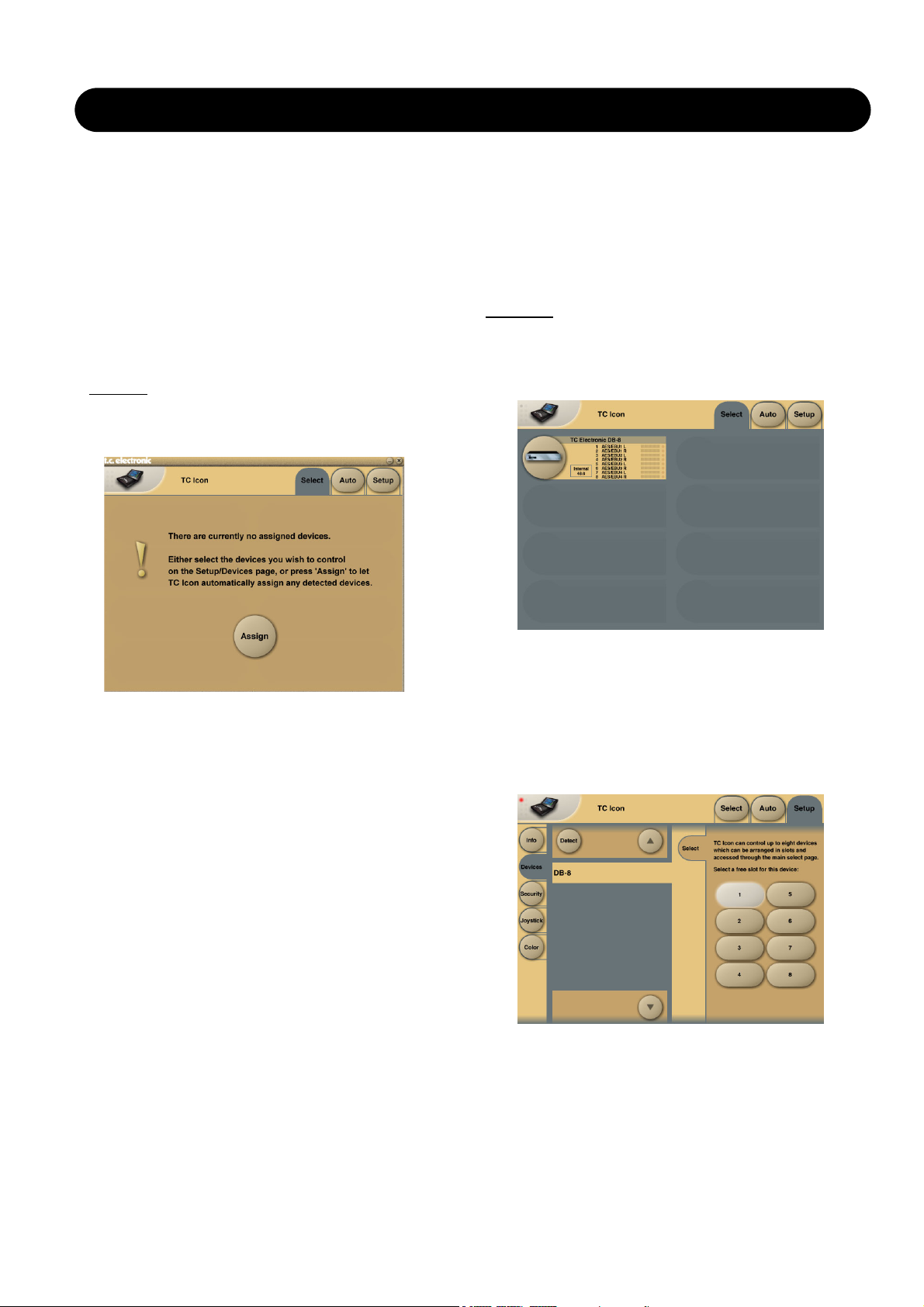
Accessing a Mainframe
First time you connect the Mainframe to the PC with
installed PC editor and network adapter:
• Power up your computer and your DB8/DB4.
• Start the Software editor and the following page appears:
• Press Assign
• All connected DB8/DB4 mainframes will be detected and
assigned to one of the 8 locations (see fig. 1).
• Press the oval key with the DB8/DB4 icon to access the
DB8/DB4.
Scanning the system
The scenario described above covers the first time you
boot up your system or when no connected units are
assigned.
To scan the system for all connected units go to the Setup
page and press Detect (see fig 2). The connected
mainframes will the appear in the left side of the display
and you can assign them to any of the 8 location illustrated
in the right side of the display by selecting the frames with
the cursors followed by pressing one of the oval keys.
Engine Structure
The core element of DB8/DB4 is the 4 Engine structure.
This structure enables you to run up to four powerful
algorithms/ presets simultaneously.
Each Engine is capable of utilizing up to 8 Inputs and 8
Outputs, depending on the selected algorithm/preset.
Up to 16 physical Input and 16 physical Output channels
can be routed in the most flexible way.
Engine Resources
The powerful and flexible DSP distribution structure lets
Page 3

3
BASIC OPERATION
Fader
Group
Selector
Function
Select
Tabs
Library, Frame &
Engine select Tabs
Operating Levels
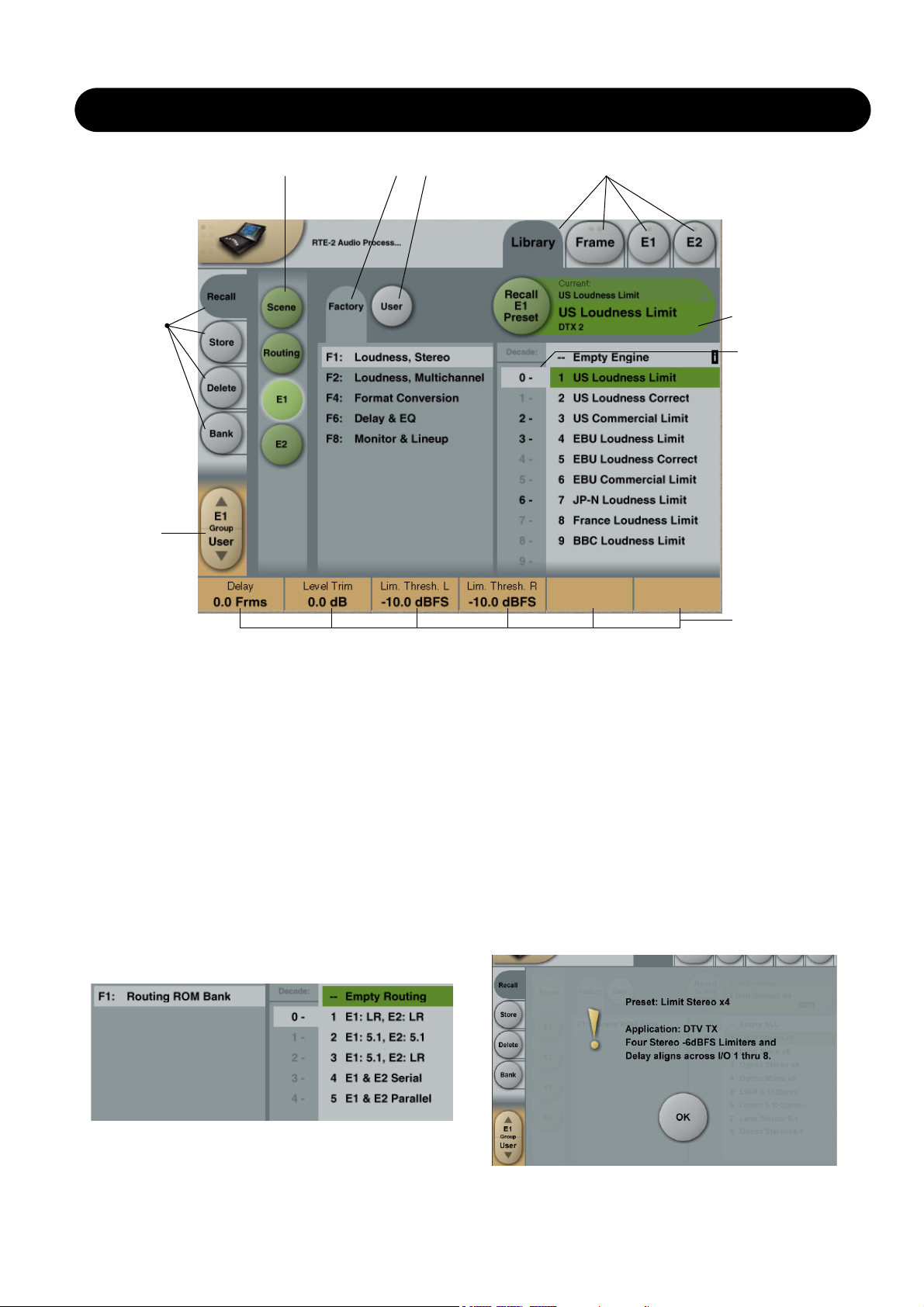
The Library-Recall page illustrated in Fig.3 leads to
explanation of the “operating levels” in the DB8/DB4. We
differentiate between 2 levels of presets:
Scene and Engine levels.
• SCENE
This is the most extensive selection you can make. It
includes all four Engine algorithms as well as physical
and virtual Engine Routings. A Scene recall can be
compared to a “total recall.”
• ENGINE
Handles the current algorithm in the selected Engine.
A single preset can be loaded to each of the four
Engines.
Parameter Values and Fader Groups
In the bottom of the display, Fader assignments and values
will always reflect the last modified Engine. Most
parameters can be controlled via the 6 Faders. As some
algorithms hold numerous parameters and we operate with
6 Faders the preset parameters are organized in Fader
Groups. To scroll between the Fader Groups use the
Fader Group selectors.
Parameter value - Fine Adjust
Any parameter value can be adjusted in two accuracies.
A Normal and a Fine Adjust - mode. To switch between the
two modes press the Value Fields above the faders.
As shown in the illustration the Fine Adjust mode will be
indicated with two triangles in the value field.
Fader 6
Any parameter can always be assigned to Fader 6 by
pressing the parameter. Detailed explanation will follow in
the next sections.
User Fader Group - Custom Group
A User Fader group where you can assign parameters to
all 6 faders can also be created and saved along with the
preset. The User Fader group is selected by pressing the
Fader Group selectors.
The Icon
LINK key
Bank Select
UI - Icon Views
On the Icon Setup page two sub-pages are available for
controlling the TC Icon appearance.
Fader appearance
Three options are available. Changes will take place next
time you open the TC Icon.
Faders at bottom
Fader at right side
No faders
Page 4
Fader
Group
Selector
LIBRARY - RECALL
Library Recall
On the Library Recall page the following banks are
available for recall operations.
Scene
Gives access to the following preset banks:
• Factory
• User
• Card (optional)
Engine 1-4
Gives access to the following preset banks:
• Factory
• User
• Card (optional)
Routing
Various standard routings can be selected.
Operation Level Tabs Bank Selectors
Function
Select
Tabs
Library, Frame and Engine selectors
Parameter Fader
values present in
the last modified
Engine.
Press “info” for
preset information
Decade selector
(“tens”)
Recalling a Scene or an Engine preset
• Press the RECALL tab to select the Recall page.
• Now select the level of: Scene or Engine 1-4.
• Select which bank you wish to recall from: Factory or
User. If a DB8/DB4 formatted PCMCIA card is inserted in
the Mainframe card-banks will be available and displayed
below the User banks.
• Select presets pressing: Bank, Decade(tens) and preset
number.
(grayed out numbers indicates that the Decade is empty)
• Press the Recall key to recall/load the preset.
Info
For presets carrying the “info” tag we have added relevant
information for the specific preset. Press Info and a pop-up
display will appear.
Example:
Page 5
5
LIBRARY - STORE
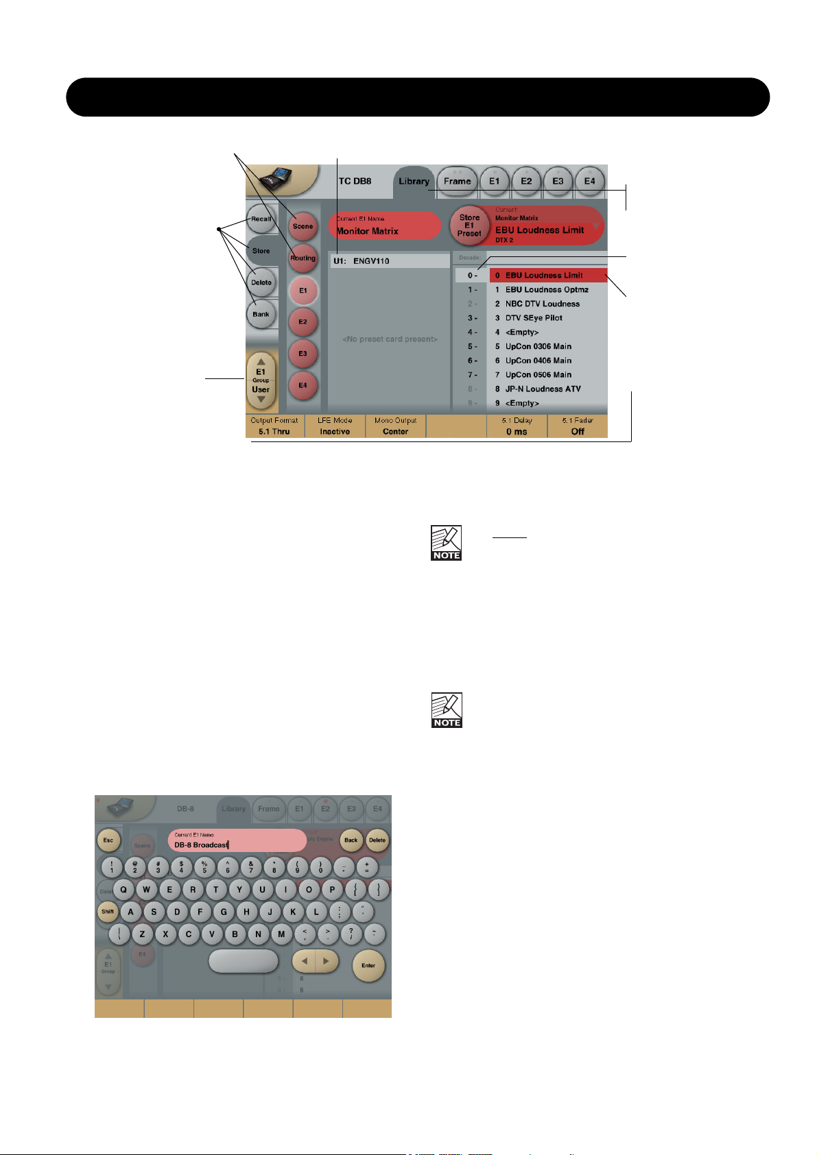
Library Store
For storing operations the following banks are available.
Scene
Allows you to store in the following banks.
• User
• Card (optional)
Engine 1-4
Allows you to store in the following banks.
• User
• Card (optional)
Storing a Preset
• Press the Store tab and select Scene or Engine level.
• Select bank (user or card) and location using Decade to
select “tens” followed by location 1-9.
(grayed out numbers indicates that the bank is empty)
• Press the Store key to store the preset.
Naming Presets
All user preset types can be renamed.
Basic operation
• Press the Name field. A keyboard will pop up.
• Type in the new name.
• Press Enter.
The preset
is not stored when the keyboards Enter
key is pressed. Only the name is entered.
To store you MUST press the red Store key on the
Store page.
The previous accessed display will always be present
beneath the keyboard. Current Fader values will be
displayed and faders can be used to adjust parameter
values.The preset is not stored when the keyboard Enter
key is pressed. Only the name is entered.
To store you MUST press the red Store key.
Fader assignments in the bottom of the display will
always reflect the last modified Engine. The Engine
Fader Group selector in the lower left corner
indicates the Engine in use.
Operation Level Tabs Bank Selectors
Library, Frame and
Engine selectors
Fader
Group
Selector
Function
Select
Tabs
Decade selector
(“tens”)
Preset location
selector (“ones”)
Page 6

6
THE LIBRARY BANK
Library - Bank
From the Library Archive page you can copy Scene,
Routing and Engine banks to and from a 3.5” disk or a
PCMCIA card. If you are using the TC Icon software
editor on an Mac or a PC, preset banks can also be
copied to and from your hard disk.
Basic Operation
Bank copying is handled as a complete User bank
transferal.
• Press Scene, Routing or Engine to select preset bank
type.
• Select “from” and “to” depending on your choice.
• Press Copy Bank.
Scene/Routing/Engine Banks
T
o/From - Bank/Floppy/File
Scene, Routing or Engine banks can be backed up and
retrieved from a 3.5” disk, a PCMCIA or a file location on a
connected computer (when using the TC Icon software
editor).
Copy Bank
Press to activate copy function between the selected
Banks.
Rename
Press to rename selected bank via the Naming pop-up
display.
Delete
Press to clear the selected Bank. You will be asked to
confirm your choice to avoid unintended deletion.
Using PCMCIA cards
To use a PCMCIA card with DB8-DB4 the card must be
properly formatted. This is done from the
Frame/System/Card page.
A
1MB PCMCIA card can hold:
1000 Engine presets in 10 banks of 100 presets
500 Routing presets in 10 banks of 50 presets
500 Scene presets in 10 banks of 50 presets
A
512kB PCMCIA card can hold:
500 Engine presets in 5 banks of 100 presets
250 Routing presets in 5 banks of 50 presets
250 Scene presets in 5 banks of 50 presets
Page 7
7
LIBRARY - DELETE
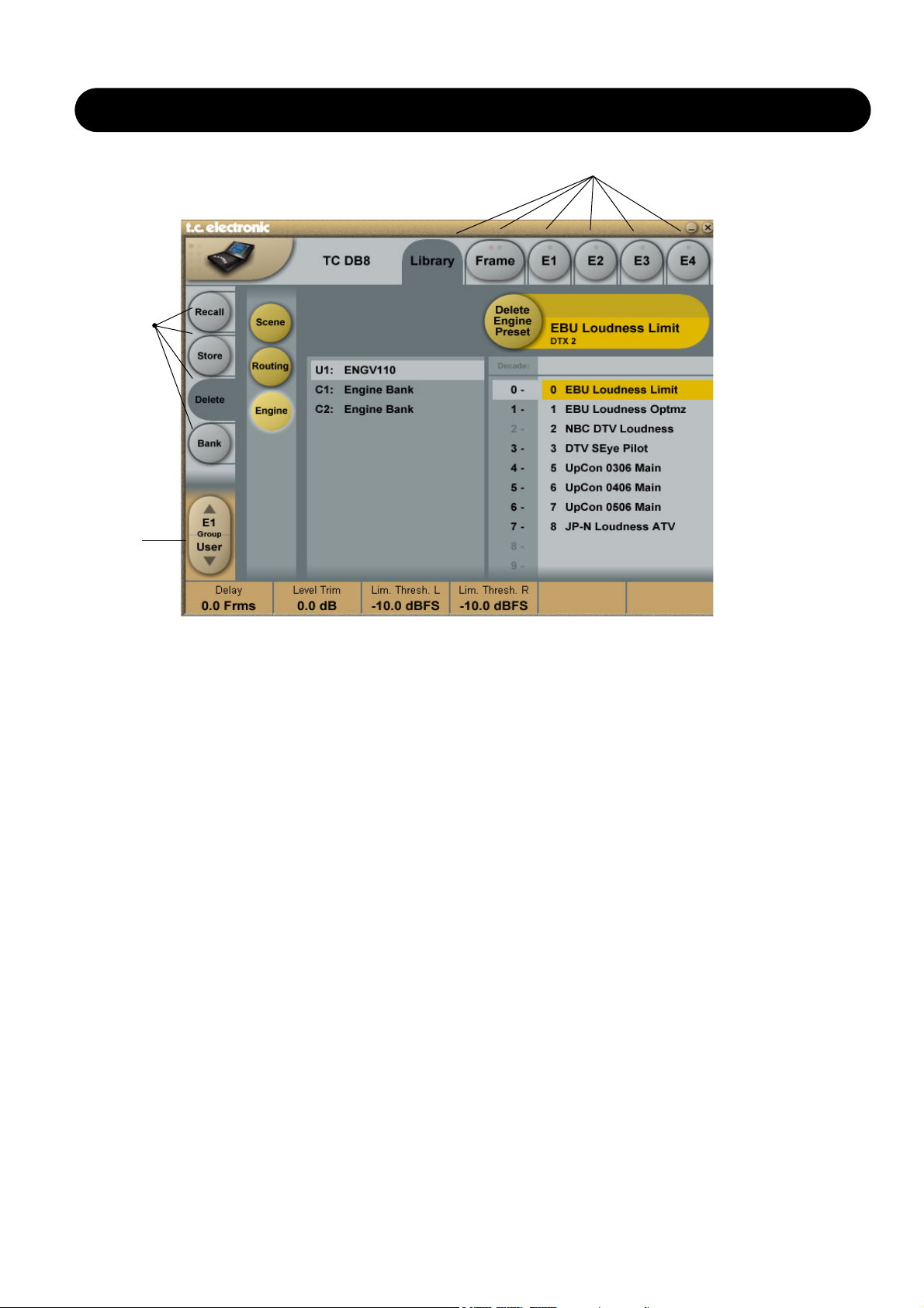
Library - Delete
For convenience it is possible to “clean up” the User
banks by deleting individual presets.
Deleting a Preset
• Select Delete (side tab) and select level by pressing
Scene or Engine.
• Select the preset to delete by pressing the actual Bank,
Decade(to select tens) and the actual preset.
• Press the Delete key to delete the preset.
Library, Frame and Engine selectors
Fader
Group
Selector
Function
Select
Tabs
Page 8

8
FRAME - ROUTING
Routing
Introduction
The Routing page is the patch-bay of the DB8/DB4
Mainframe. All routings of physical Inputs/Outputs as well
as internal routing between the Engines are setup here.
The understanding of this page is therefore essential to
operating the DB8/DB4.
To access the Routing Page:
• Press Frame (upper tab)
• Press Routing (side tab)
• Press Route to enable routing facilities
This is the p
age where you:
• Have the overall view of all I/O’s
• Route physical Inputs to Engine Inputs
• Route Engine Outputs to physical Outputs
• Access Input and Output meters
Routing Inputs
• Press the Route key to select route operation.
• Press ENGINE 1 to 4 to select the Engine you
wish to route
• Select a physical Input or another Engine's Output using
Fader 1
• Select Engine Input using Fader 2
Routing Outputs
• Press the Route key to select Route operation
• Press Engine 1 to 4 to select the Engine you wish to
route
• Select an Engine Output using Fader 5
• Select Physical Output using Fader 6
The I/O possibilities are as follows
• It is possible to connect any physical Input to several
Engine Inputs (up to 32), however, it is not possible to
connect more than one physical Input to the same
Engine Input.
• It is possible to connect all Engine Outputs (up to 32) to
one single physical Output.
• It is possible to connect an Engine Output to the Inputs
of the three other Engines.
Engine Processing Delay
Processing delay between the routed Engines
behaves as if they were external devices.
Labels
The Input/Output fields can show either meters or the
Labels/names on the Input/Output channels. To switch
between the two modes press “Labels”.
Renaming Physical Inputs and Outputs
Input and Output channels can be labeled individually. This
is a global renaming process and is accessed by pressing
System (side tab) followed by I/O and Labels. After that
follow the naming procedure described on page 6.
Meters
Engine I/O Meters
Engine I/O meters are shown at the left and right of the
large E 1-4 buttons in the middle of the display. The
number of meters shown will always reflect the number of
I/O channels in the loaded algorithm.
Frame - E1 to E4/E2 (DB8/DB4)
This page holds the User group parameters for all four
Engines. Selecting User group parameters is done from the
Engine pages. Values can be altered from both the Engine
Edit pages and the page displayed above. Press the
parameter you wish to assign to the Fader located below.
Page 9

9
FRAME - SYSTEM - MAIN
Clock
Clock Settings
Clock Master
Select the clock source for the complete Mainframe,
including all Engines and all I/O’s.
Select between:
Internal, Wordclock, AES 1-2, 3-4, 5-6 or 7-8.
Locking to an external source will take approx.. 7 sec.
It is not necessary to have the physical Input
routed to an Engine Input to have the clock accepted.
Internal Clock Rate
The internal Clock Rate can be set to 44.1 or 48kHz.
As it is considered “unconventional” to use the DB8 internal
clock in broadcast setups, a yellow indication will appear
on the frame select page when internal is selected.
Auto Revert to Internal
Press to activate. If an external clock source is selected
and this clock is lost, DB8 will automatically switch to the
selected internal clock-rate with this function active.
Notice that “auto revert to internal” will work only
if a
valid clock on the selected Clock Master, has be
present at one point and then lost. If DB8 at no point
has been locked to a valid clock on the selected
Clock master input the “Locked Clock Rate” field will be
red. Red means: no output.
Clock Status
Locked Clock Rate
The Clock Rate to which the Mainframe is currently locked.
Color indications
The yellow color indicates that:
- Auto Revert to Internal is selected and...
- the selected Clock Master has been present at one point
but is now lost and...
- the frame has switched to the selected internal clock rate.
The red color indicates “no lock” - check cables and clock
source.
SMPTE
Reader Enabled
On/Off switch for the DB8/DB4 SMPTE Reader.
Frame Rate
Range: 24 FPS, 25 FPS, 29.97 FPS,
30 Drop FPS, 30 FPS.
Running Status
The small field in the top left corner of the numeric display
will state “Running” when SMPTE clock is running.
Detected Sample Rate
This is a read-only parameter indicating the actual
incoming Sample Rate. The tolerance of this detection is
+/- 10Hz.
Example:
An incoming Sample Rate of 44.056kHz will be
detected as approx. 44.06kHz and the system indicates the
Locked Clock Rate 44.100kHz.
The system will lock to and reject jitter at any Sample Rate
between:
• 30 - 34kHz
• 42.5 - 45.5kHz
• 46.5 - 48.5kHz
Page 10

10
FRAME - SYSTEM - MAIN - GPI
DB4 and DB8 GPI Specification
DB4 and DB8 offers a GPI input for remote switching between Scenes (all Engine Presets plus Routing). The input can be
used for daily operation, or for backup and redundancy purposes. It allows change between 2, 4 or 8 presets using just
one connection.
Basic operation
GPI functions are accessed from the System/Main/GPI page in TC Icon.
Enable Recall
Off
2 Presets
3 Presets
4 Presets
7 Presets
8 Presets
Select between Scenes
GPI Recall disabled
User Scene 0-1
User Scene 1-3
User Scene 0-3
User Scene 1-7
User Scene 0-7
Notes
Make sure this state is selected, if GPI recall is not being used.
User Scene 0 or 1 is permanently recalled.
Note: Switching to this mode will instantly perform a Scene Recall,
even if no connections are made to the GPI input.
As long as the GPI input is idle (+5V), GPI recall is inactive. In idle
mode, the machine can be normally controlled from Icon, or using
the serial data input.If active GPI windows 1, 2 or 3 are selected,
the corresponding Scene is recalled, and the serial data control
input is disabled.This GPI mode is suitable for Backup and Alarm
messaging operation.
User Scene 0, 1, 2 or 3 is permanently recalled.OBS: Switching to
this mode will instantly perform a Scene Recall, even if no
connections are made to the GPI input.
As long as the GPI input is idle (+5V), GPI recall is inactive. In idle
mode, the machine can be normally controlled from Icon, or using
the serial data input.If active GPI windows 1-7 are selected, the
corresponding Scene is recalled, and the serial data control input is
disabled.This GPI mode is suitable for Backup and Alarm
messaging operation.
User Scene 0, 1, 2, 3, 4, 5, 6 or 7 is permanently recalled.OBS:
Switching to this mode will instantly perform a Scene Recall, even if
no connections are made to the GPI input.
The Enable Recall parameter can be set to Off (GPI
recall disabled), 2, 3, 4, 7 and 8 presets.
Presets are selected as a state condition, i.e. presenting
the GPI input a permanent voltage signifying a specific
preset.
Page 11

11
FRAME - SYSTEM - MAIN - GPI
Installation
Selection between up to 8 presets is achieved by feeding the processor a DC voltage to the 1/4" jack input labeled "Pedal".
The input voltage is compared against voltage windows that correspond to certain presets.
Between the valid voltage windows, invalid windows have been inserted to protect against erratic operation. The processor
constantly monitors the GPI input, and only if several consecutive measurements point to the same, valid voltage window,
a recall is performed.
The voltage windows chosen enable easy "binary relay encoding" as shown in fig. 1. If long cable runs are required, HF
decoupling using a ceramic capacitor across the Tip and Sleeve terminals inside the jack plug may be indicated.
Note: The ring terminal of the 1/4" jack is not used.
Fig 1, Relay coding of 2, 4 and 8 preset GPI configurations
Page 12

12
FRAME - SYSTEM - MAIN - GPI
GPI Technical specifications
Inside the processor, a 10kohm resistor connects the Tip terminal to a +5V power supply. When nothing is connected to
the GPI input, the input voltage therefore is +5V. Resistors can be used to pull down the voltage as suggested in Fig 1.
In Table 1, voltages outside the limits mentioned are to be considered invalid. No action is taken if invalid measurements
are made. GPI recall action resumes when a stable, valid measurement again is detected.
Mode
1 of 2
1 of 4
1 of 8
Preset No
0
1
0
1
2
3
0
1
2
3
4
5
6
Target / Vs
1.000 (idle)
0.000
1.000 (idle)
0.687
0.545
0.438
1.000 (idle)
0.824
0.687
0.600
0.545
0.489
0.437
0.400
Target typ / V
5.00
0.00
5.00
3.44
2.73
2.19
5.00
4.12
3.44
3.00
2.73
2.44
2.19
2.00
Max typ / V
5.00
0.51
5.00
3.50
2.79
2.25
5.00
4.18
3.50
3.06
2.79
2.50
2.25
2.06
Min typ / V
2.67
0.00
4.16
3.38
2.67
0.00
4.50
4.06
3.38
2.94
2.67
2.38
2.13
0.00
Tech Notes:
"Idle" refers to the state when no input is connected, or when the input is left floating.
Rather than absolute voltage measurements, the windows are defined as a fraction of
the supply voltage, Vs. This voltage can be measured with a high impedance DMM on
the Tip terminal when no pull down resistors are applied.
The table shows values as a fraction of Vs, and, as a guideline, typical voltages when
Vs=5.000V. (If the Supply voltage is e.g. 5.015V, the table should be corrected by
multiplying these values by 5.015/5).
Page 13

13
FRAME - SYSTEM - MAIN
Normal mode
In Normal mode all banks can be accessed for program
changes. Bank selection is done via Ctrl 0 (MSB) and
Ctrl 32 (LSB):
• Controller 0 must be set to 0 in all cases.
• Controller 32 value must match the bank number you
wish to address according to the table below.
Ctrl 32 value 0 - F1: Loudness, Stereo
Ctrl 32 value 1 - F2: Loudness, Multichannel
Ctrl 32 value 2 - F3: Reserved
Ctrl 32 value 3 - F4: Format Conversion
Ctrl 32 value 4 - F5: Reserved
Ctrl 32 value 5 - F6: Delay and EQ
Ctrl 32 value 6 - F7: Reserved
Ctrl 32 value 7 - F8: Monitor and Lineup
Ctrl 32 value 8 - F9: Reserved
Ctrl 32 value 9 - F10: Reserved
Ctrl 32 value 10 - F11: Reserved
Ctrl 32 value 11 - F12: Reserved
Ctrl 32 value 12 - F13: Reserved
Ctrl 32 value 13 - F14: Reserved
Ctrl 32 value 32 - User bank
Ctrl 32 value 64 - Card Bank 1
Ctrl 32 value 65 - Card Bank 2
Ctrl 32 value 66 - Card Bank 3
- - - - -
Ctrl 32 value 73 - Card Bank 10
Example:
You wish to recall preset 10 from the Reverb (Music
Surround) bank. According to the table above:
• Set Ctrl 0 to “0” and Ctrl 32 to “2” and send program
change no 10.
SysEx Device ID
Range: 0 to 126
Select SysEx ID for the Mainframe.
MIDI Rate
Range: Normal or 19.2
This parameter sets the Baud Rate / MIDI transfer rate.
The default setting is “Normal”. However, “19.2” may be
better suited for external master control programs as found
in broadcast stations.
MIDI Setup Page
Introduction
MIDI Channels
To recall presets for Scene, Routing and Engines 1 to 4
you must first setup individual MIDI channels for these
categories.
In the example above we have setup MIDI channels 1 to 4
for Engines 1 to 4 respectively; channel 5 to access Scene
presets and channel 6 to access Routing presets.
Bank Mode
The Bank mode settings determine the destination bank of
the received program change on the specified MIDI
channels.
Normal mode:
This mode requires that the external sending MIDI device
can send both Controller 0 and 32 in addition to MIDI
program changes. This is an essential feature to recall
presets from a device holding more than 128 preset
location. (see table in next column for details)
Factory and User mode:
These modes will force any incoming program change to
access either Factory or User banks directly and are
typically used if your sending MIDI device cannot send
Controllers 0 and 32 as described above.
Page 14

14
FRAME - SYSTEM - MAIN
MIDI Control Page
On MIDI Control Page the following options are
available:
Read Program Change
Select whether the Frame should read incoming program
changes or not.
Send Program Change
Select whether the Frame should send program changes to
MIDI out when presets are recalled via TC Icon or the TC
Icon Software editor.
Read Control Change
Select whether the Frame should Read Control Changes
messages.
Send Control Change
Options here are Single (7 bit) or Double (14 bit) precision.
Read SysEx - Send SysEx
These two parameters determine whether the Frame
should read and send SysEx.
MIDI MIDI Page
Page 15

15
FRAME SYSTEM MAIN
Net
Software versions
Current installed software versions.
Network Identifier
Press the field “Network Identifier” to enter a name for the
Mainframe. This is the global TC network name for the
frame. By giving the frame a specific name it will be easier
to identify the frame when hooked up in a network with
several frames.
Card
Format card with empty preset banks
This function will format a PCMCIA card with DB8/DB4
preset banks. A formatted 1Mb card will hold:
• 10 Engine user card banks of 100 presets
• 10 Routing user banks of 50 presets
• 10 Scene user banks of 50 presets
Dump Binary File to Card
This function enables you to dump a binary file to a
PCMCIA card. Follow the steps below:
This is for service purposes only!
• Rename the xxx.bin file to “dumpfile.bin
• Copy the file to a 3.5” disk
• Insert the disk in the DB8/DB4 3.5” disk drive
• Insert a memory card in the DB8/DB4
• Press Dump Binary File to Card and confirm to
proceed.
Page 16

16
FRAME - SYSTEM - I/O
Via the I/O page the following operations are handled:
• Settings for the DSP card
• Settings for up to three I/O cards
• Labeling of all physical Input and Output channels
Basic operation
If more than one mainframe is connected:
• Press the Icon symbol in the upper left corner to enter
the Select & Setup pages
• Select which mainframe you wish to setup
• Press the Icon symbol once again and and select
System - I/O as illustrated above
I/O - SETUP
With this page you can monitor the Mainframe
configuration
Analog Input - Digital Input
With an AES-8 card installed in a Mainframe, you must
select whether Input channels 9 through 16 should be
digital or analog.
When Digital Input is selected:
Input channels 9-16 will be the AES-8 card.
When
Analog Input is selected:
Only analog Inputs are available!
If an ADA-24/96 card is installed in slot A analog Input
channels 9-10 are available.
If ADA 24/96 cards are installed in both slot A and C,
analog Input channels 9-10 and 13-14 are available.
Please note the following:
• No Inputs on the AES-8 card are available when analog
Input is selected.
• Digital Input must be selected to activate AES-8 card
Input channels 9-16 even if no ADA 24/96 cards are
present.
• Outputs 9-16 are always available. If ADA-24/96 cards
are installed, they will output simultaneously with the
AES-8 Outputs on channel 9-10 (Slot A) and 13-14 (Slot C).
I/O - DSP
Status Bit
Status bit information can be set separately for each of the
AES Outputs.
Options are:
AES/EBU : Professional usage of Status bits.
S/PDIF : Consumer usage of Status bits.
Clock Status - Sample Slip Detection
Input 1-2, Input 3-4, Input 5-6, Input 7-8
Input 9-10, Input 11-12, Input 13-14, Input 15-16
Monitors the Clock status of the incoming AES/EBU
Inputs and indicates whether the incoming Clock is in sync
with the mainframe Clock settings. Three states of
incoming clock can be indicated.
Locked
The Input is in sync with he Mainframe.
Sync Error (Red)
The Input is or has been out of sync with the mainframe.
Press the Reset key to see if Sample Slips are still
occurring. - If so - Check that there is only one
Master
Clock source in your setup. This monitoring function is
excellent when trying to determine which connected device
is out of sync.
No Input
Indicates no connection available.
Page 17

17
FRAME - SYSTEM - I/O
Output, pin 2 selected
Pin 2 hot, pin 3 connected to reference (shield) at the Input
of downstream device. In this mode pin 3 acts as a
reference Input for the ADA24/96 Output stage and should
not be left unterminated.
This mode will not work properly with balanced
inputs unless wiring is compensated as described. If
wired properly, this is the optimum output mode for
feeding unbalanced devices.
Output, pin 3 selected
Pin 3 hot, pin 2 not needed. In this mode pin 2 and pin 1
carry the same output reference.
This works with balanced inputs using 1:1 wiring,
but balanced mode should be selected if driving a
balanced input.
Filters
When operating the mainframe in normal Sample Rates
(32 - 48kHz) you can select different down- and
up-sampling filter types. The AD and DA conversions are
always performed in high-sample domain (88.2 to 96kHz).
Afterwards the digital down- and up-sampling is performed
in the digital domain using a local DSP on the ADA24/96
card. Select filter type according to the source material you
are working on.
Filters
Chose between - Linear, Natural, Vintage, Bright and
Standard (Std).
"Linear" filter
These filters are linear-phase and non-aliasing (the stopband starts below the Nyquist frequency). The pass-band
response is extremely smooth and non-equiripple,
extending beyond 20kHz. With the "Linear" filters you'll
have a hard time discriminating between the sound of the
conversion chain and direct analog, even at 44.1kHz!
"Natural" filter
Based on the "Linear" filter class, but with a carefully
adjusted non-linear phase response, these filters obtain an
almost "better-than-live" reproduction of space while
retaining crystal-clear imaging and absolute tonal neutrality.
The "Natural" filters too are non-aliasing.
"Vintage" filter
Based on the "Natural" filters, here we've added a bit of
warmth and roundness to the treble by introducing a
smoother "tube like" roll-off. This filter would be an
exceptionally good choice when mastering material that
seems too hard in the high-end frequencies.
These filters too are non-aliasing and non-linear phase.
I/O - Slot A, B & C
This is where you setup card specific parameters.
Parameters are only available when a I/O Card is detected.
ADA 24/96 card
Level In
Changes the analog nominal Input level between +6dBu
and +30dBu in 6dB increments.
The analog Input level enables you to match the DB8/DB4
Input to the Output of e.g. your mixer. If the nominal
operating level on your mixer is e.g. +4dBu and you select
+12dBu on the Level In parameter you will have a
headroom of 8dB. If you select +16dBu in the Level In the
headroom will be +12dB, and so forth.
Level Out
Changes the analog output level between +6dBu and
+24dBu in 6dB increments.
Output Connection
Select the type of connection you are using on the Output
of the card. Select between:
Balanced or unbalanced (with signal on pin 2 or pin 3).
If you are connecting unbalanced cables to the
Outputs when Outmode set to “Balanced”, the
Outputs will be muted/un-muted sequentially
via a goldplated short circuit protection relay.
This is intentional and will not cause damage
to any device.
Balanced/Unbalanced Operation
Unbalanced operation
Some mastering studios prefer unbalanced wiring.
Please read these notes for optimum performance.
Preferably, balanced cables should be used on Inputs and
Outputs even for unbalanced setups.
Input
Pin 2 hot, pin 3 connected to reference (shield) at the
Output of upstream device.
Page 18

18
FRAME - SYSTEM - I/O
I/O - Labels
All physical Inputs and Outputs can be named/renamed.
Enter the Titles page by pressing the tabs System and
Titles. Press any of the 16 Inputs/Outputs and the Naming
display will pop up. Enter adequate name for the
Input/Output and press Enter.
The names will be displayed on the Frame-Routing page.
The I/O Labels are global and are not affected by
preset changes.
"Bright" filter
These filters are something entirely different: Ultra-short
impulse response, linear phase and quite a bit of deliberate
aliasing produces a "digital" and slightly aggressive sound
adding plenty of top-end life to e.g. Rock and Techno
recordings, or giving you the feeling of air you need when
you are mastering a somewhat dark sounding source
material.
"Standard" filter
This filter emulates the response of typical mid-end
converters: Equiripple half-band filters that are precisely
6dB down at the Nyquist frequency.
Softclip
The Softclip algorithm runs in the 96kHz domain right after
the AD conversion before the down-sampling filter.
AES-8 Card
Slot B with an
AES-8 card installed
The following Setup page will appear in:
Frame/System/I/O/Setup when an AES-8 card is
installed.
Analog Input - Digital Input
With an AES-8 card installed in a Mainframe, you must
select whether Input channels 9 through 16 should be
digital or analog.
When Digit
al Input is selected:
Input channels 9-16 will be the AES-8 card.
When
Analog Input is selected:
Only analog Inputs are available!
If an ADA-24/96 card is installed in slot A analog Input
channels 9-10 are available.
If ADA 24/96 cards are installed in both slot A and C,
analog Input channels 9-10 and 13-14 are available.
Please note the following:
• No Inputs on the AES-8 card are available when analog
Input is selected.
• Digital Input must be selected to activate AES-8 card
Input channels 9-16 even if no ADA 24/96 cards are
present.
• Outputs 9-16 are always available. If ADA-24/96 cards
are installed, they will output simultaneously with the
AES-8 Outputs on channel 9-10 (Slot A) and 13-14 (Slot C).
Page 19

19
ENGINE - EDIT PAGE
Fader Group
Parameters/
Value fields
Output
Meters
Display
function
indicator
Input
Meters
Library Frame and Engine SelectorsName of the currently
recalled preset
Fader
Group
Selector
Parameter
Pages
Link key
Fine Adjust
Mode
selected
The Engine 1-4 Edit Pages
This is where you edit algorithm parameters.Parameters in
several algorithms are distributed on different pages. As
illustrated above the Multiband-2 has 5 pages: Main,
Loudness, EQ, 5 band and Limiter. Depending of the
quantity of parameters represented in the groups one or
more groups will be displayed.
Basic operation
• Press E1 to E4 to select Engine. Parameters for the
recalled algorithms are instantly available for editing.
• Select a parameter group. In the example above - a
Multiband-2 algorithm - the groups are Main, Setup,
Expander, Compressor, Limiter and Output.
• All parameters are assigned to the Fader Groups. Select
Fader Group using the Fader Group selector.
• Press any parameter and it is assigned to Fader 6.
Fader User Group - Assign key
By pressing the Fader Group Selector Up key you enter
the User group. In this group you can assign any
parameter to any Fader. The User Fader group is stored
with a preset.
• Press the Link key.
• Select the Fader you wish to link a parameter to, by
pressing the field just above the fader.
• Press the parameter you wish to link to the selected
fader.
Bypass
The Bypass key will respond in different ways depending
on the recalled algorithm. See specific algorithm description.
In some algorithms the Bypass will work as a mute
function.
Naming a Preset
• Press the Name field. A keyboard will pop up.
(See the “Naming display” section).
• Type in the new name.
• Press Enter.
Parameter value - Fine Adjust
Any parameter value can be adjusted in two accuracies.
A Normal and a Fine Adjust - mode. To switch between the
two modes press the Value Fields above the faders.
As shown in the illustration the Fine Adjust mode will be
indicated with two triangles in the value field. (fader 3+4 in
the illustration).
Page 20

20
ICON SETUP
Icon User Interface
(only available on the Hardware version of the TC Icon)
Go to the Select & Setup pages pressing the TC Icon
key in the upper left corner.
Press SETUP (upper tab) and UI (side tab) to enter the
setup page for the TC Icon display.
TC Icon Display Parameters
In this display you setup various parameters regarding the
appearance of the display as well as the Fader Touch
Sensitivity.
Display Brightness
Adjust the brightness of the display using either the Arrow
cursors or simply drag the “Adjust handle”.
Show Mouse Cursor
Press to show mouse/pointer position.
Calibrate Display Touch
For optimal performance the Touch Screen will at times
need to be calibrated. Press and follow instructions to
Calibrate the Touch Screen.
Fader Sensitivity
To avoid accidental movement of the faders they are
sensitive to humidity and will only respond when touched
by your skin.
Enable Fader
Touch
Enables touch sensitivity of the Faders.
AC/DC Sensitivity
Sets the Faders sensitivity to AC and DC. Adjust these
handles to achieve optimal performance in your
environment.
Software Editor Setup menu
Info
On this page the current Software Editor version number is
listed.
Devices
In this page you control and assign the devices in the
setup.
• Press Detect to scan the network for connected
devices. All devices will appear in the list.
• Now assign the devices one at a time by selecting the
device using the Cursor up/down followed by pressing
one of the eight oval keys in the right side of the display.
Security
In the security page you can activate/deactivate the “sticky
clip” function.
When this function is set to “on” the Overload LEDs on the
Routing page will stay lit once activated, until the Reset
Clip key is pressed.
Color
Select the Color scheme of your choice. Depending on the
surrounding light conditions different schemes may be
more appropriate than others.
Page 21

21
SMPTE
Auto Edit Page
In the Auto Edit page all automation Events are listed and
handled.
Keep
Press to save the Event List locally on the Icon. It is possible
to save one Event List on the Icon. Additional cue-lists can
be stored and recalled on floppy disks on the Mainframe.
The Keep key will turn red as soon as any editing of the list
has taken place, indicating that you must press to save the
list.
This key corresponds/is the same, as the Keep key located
on the File page. (see following page)
Write
When enabled any program change is written to the
SMPTE Event List. This can be. e.g Engine, Routing or
Scene recalls.
Read
When enabled the Event list will be executed according to
incoming SMPTE clock. Read and Write functions can be
activated simultaneously.
General Read and Write status is given in the
Icon Tab in the left corner.
Follow
When follow is selected the list will scroll and the current
event/song position will always be in the top line.
When follow is de-selected the list will NOT scroll but the
cursor position will move according to song-position.
Save
Press to save the Event list. The Save key will turn red as
soon as any editing of the list has taken place, indicating
that you must press to save the list.
This key corresponds/is the same, as the Save key located
on the file page. (see next page)
Be aware that until Save is pressed Edited SMPTE
information is not yet stored in the Event list. For
convenient indication the Save key will be red as soon as
any alteration of the current Event list is present.
Cursor
The white triangular cursor always indicates the current
clock position in relation to the Event List.
Event Parameters
For each Event the following parameters are available.
Time - indicates the SMPTE time at which the Event
takes place.
Device - indicating on which Device Mainframe the
Event is taking place. Device numbers 1-8,
corresponds to the Device position at the
Select page.
Event - states the occurring Event at the given time.
Modify
Press this key to access Event parameters for the currently
selected Event. (see further description below)
Delete
Press to delete the selected Event.
Insert New Event
Press to insert an Event (see further description below)
Modify/Insert - Edit
Event Settings
Operation
• To access Event settings press Modify in the Edit page.
• Setup all parameters for the Event you are about to
Modify or Insert.
• Press OK to confirm.
Time
The time where the Event being Modified or Inserted
is taking place.
Step/Adjust
Range: Frame, 1 Second, 10 Seconds, 1 min.,
10 min. or 1 hour.
Use the Step parameter to select Adjust range and the
Adjust parameter to increase/decrease the time.
Page 22

22
SMPTE
Device
This parameter selects which Mainframe connected to the
LAN you are working on. Device numbers 1-8, corresponds
to the Device position at the Select page.
Preset Type
Selects whether the preset Event you are working on is a
Scene, Routing, Engine or a System preset.
Bank
Select the bank related to the preset you are about to
setup/recall via SMPTE.
Preset
Select the preset from the selected bank
File
Current List
Keep
Press to save the Event List locally on the Icon. It is possible
to save one Event List on the Icon. Additional cue-lists can
be stored and recalled on floppy disks on the Mainframe.
The Keep key will turn red as soon as any editing of the list
has taken place, indicating that you must press to save the
list.
This key corresponds/is the same, as the Keep key located
on the Edit page. (see previous page)
Revert
This “Undo” function allows you to revert the to the last
saved SMPTE Event list. This is the List that is stored
locally on the TC Icon.
Clear
Press Clear to delete the entire SMPTE Event list present
in the TC Icon.
Remote device disk drive
Event lists can easily be organized and saved to a Floppy
disk in the Mainframe.
Mainframe selection is done in the Auto Edit page.
Get List
Press to get a list of all SMPTE Event lists stored on the
floppy disk located in the Mainframe.
New
Press New to create and name a new Event list in the
floppy disk in the Mainframe.
Save
Press to save the current Event list to the disk.
Load
Press to load Event list from disk.
Delete
Press to delete selected Event preset from the
Event Preset list.
Options
Automation Timecode Options
Master Sync Device
Select which of the Mainframes connected on the LAN you
wish to act as Master Clock.
Start Of Daytime
Range: 23:00:00:.00 or 00:00:00:00
If the SMPTE time code present on your tape media or film
does not start exactly at the beginning of the tape the
23:00:00:00 setting would be a good choice to keep
chronological order in the Event List.
Support of SNMP
Multiple DB8 and/or DB4 units can be monitored using
industry standard SNMP trapping. SNMP includes
monitoring of sync status, overload, silent outputs and
more. - Look on www.tcelectronic.com under “Products DB8/DB4” for details.
 Loading...