

Taylor Freezer C708, C716 Operation Manual

Models C708 & C716
Heat Treatment
Soft Serve Freezer
Operating Instructions
059061--M
January, 2005 (Original Publication)
(Updated October, 2010)

Complete this page for quick reference when service is required:
Taylor Distributor:
Address:
Phone:
Service:
Parts:
Date of Installation:
Information found on the data label:
Model Number:
Serial Number:
Electrical Specs: Voltage Cycle
Phase
Maximum Fuse Size: A
Minimum Wire Ampacity: A
E January, 2005 Taylor (Original Publication)
(Updated October, 2010)
All rights reserved.
059061--M
The word Taylor and the Crown design
are registered trademarks in the United States
of America and certain other countries.
Taylor Company
750 N. Blackhawk Blvd.
Rockton, IL 61072

Table of Contents
Section 1 To th e Installer 1............................................
Installer Safety 1........................................................
Site Preparation 1.......................................................
Air Cooled Units 2.......................................................
Water Connections (Water Cooled Units Only) 2............................
Electrical Connections 2.................................................
Beater Rotation 3.......................................................
Refrigerant 3...........................................................
Section 2 To the Operator 4...........................................
Compressor Warranty Disclaimer 4.......................................
Section 3 Safety 5....................................................
Section 4 Operator Parts Id entification 7...............................
Model C708 7..........................................................
Model C716 8..........................................................
Model C708 Single Spout Door and Beater Assembly 9......................
Model C716 Door and Beater Assembly 10..................................
X57029-XX Pump A. - Mix Simplified (Model C708) 11........................
X57029-XX Pump A. - Mix Simplified (Model C716) 12........................
Accessories 13..........................................................
Brush A.-Package-HT X44127 14..........................................
Section 5 Important: To the Operator 15.................................
Symbol Definitions 16....................................................
Operating Screen Descriptions 17..........................................
Freezer Locks 20........................................................
Manager's Menu 22......................................................
Section 6 Operating Procedures 30.....................................
Freezing Cylinder Assembly 30............................................
Freezer Door Assembly 32................................................
Mix Pump Assembly 35...................................................
Sanitizing 38............................................................
Priming 40..............................................................
Daily Closing Procedures 41..............................................
Daily Opening Procedures 42..............................................
Table of Contents Models C708 & C716

Table of Contents - Page 2
Manual Brush Cleaning 43................................................
Draining Product From T he Freezing Cylinder 43............................
Rinsing 44..............................................................
Hopper Cleaning 44......................................................
Disassembly 45..........................................................
Brush Cleaning 46.......................................................
Section 7 Important: Operator Checklist 47..............................
During Cleaning and Sanitizing 47.........................................
Troubleshooting Bacterial Count 47........................................
Regular Maintenance Checks 47...........................................
Winter Storage 48........................................................
Section 8 Troubleshooting Guide 49....................................
Section 9 Parts Replacement Schedule 53...............................
Section 10 Parts List 54.................................................
Wiring Diagrams 70......................................................
Note: Continuing research results in steady improvements; th erefore, information
in this manual is subject to change without notice.
E January, 2005 Taylor (Original Publication)
(Updated October, 2010)
All rights reserved.
059061--M
The word Taylor and the Crown design
are registered trademarks in the United States
of America and certain other countries.
Models C708 & C716 Table of Contents
Taylor Company
750 N. Blackhawk Blvd.
Rockton, IL 61072
Section 1 To the Installer
The following are general installation instructions.
For complete installation details, please see the
check out card.
cause severe injuries.
Installer Safety
This unit has many sharp edges that can
In all areas of the world, equipment should
be installed in accordance with existing local codes.
Please contact your local authorities if you have any
questions.
Care should be taken to ensure that all basic safety
practices are followed during the installation and
servicing activities related to the installation and
service of Taylor equipment.
S Only authorized Taylor service personnel
should perform installation and repairs on
the equipment.
S Authorized service personnel should consult
OSHA Standard 29CFRI910.147 or the
applicable code of the local area for the
industry standards on lockout/tagout
procedures before beginning any installation
or repairs.
S Authorized service personnel must ensure
that the proper PPE is available and worn
when required during installation and
service.
S Authorized service personnel must remove
all metal jewelry, rings, and watches before
working on electrical equipment.
The main power supply(s) to the freezer
must be disconnected prior to performing any
repairs. Failure to follow this instruction may result in
personal injury or death from electrical shock or
hazardous moving parts as well as poor
performance or damage to the equipment.
Note:Allrepairsmustbeperformedbyan
authorized Taylor Service Technician.
Site Preparation
Review the area the unit is to be installed in before
uncrating the unit making sure that all possible
hazards the user or equipment may come into have
been addressed.
For Indoor Use Only: This unit is designed to
operate indoors, under normal ambient
temperatures of 70_-75_F(21_-24_C). The freezer
has successfully performed in high ambient
temperatures of 104_(40_C) at reduced capacities.
This unit must NOT beinstalledinanarea
where a water jet or hose can be used. NEVER use
a water jet or hose to rinse or clean the unit. Failure
to follow this instruction may result in electrocution.
This unit must be installed on a level surface
to avoid the hazard of tipping. Extreme care should
be taken in moving this equipment for any reason.
Two or more persons are required to safely move
this unit. Failure to comply may result in personal
injury or equipment damage.
Uncrate the unit and inspect it for damage. Report
any damage to your Taylor Distributor.
This piece of equipment is made in the USA and has
USA sizes of hardware. All metric conversions are
approximate and vary in size.
081208
Models C708 & C716 To the Installer
1
Air Cooled Units
DO NOT obstruct air intake and discharge openings:
Electrical Connections
Model C708: Requires a minimum of 6” (152 mm) of
clearance on both sides and 0” in the rear of the
unit.
Model C716: Requires a minimum of 3” (76 mm) of
clearance on all sides. Install the deflector provided
to prevent recirculation of warm air.
This will allow for adequate air flow across the
condensers. Failure to allow adequate clearance can
reduce the refrigeration capacity of the freezers and
possibly cause permanent damage to the
compressors.
Water Connections
(Water Cooled Units Only)
An adequate cold water supply must be provided
with a hand shut-off valve. On the underside of the
base pan or on the right side, two 3/8” I.P.S. water
connections for inlet and outlet are provided for easy
hook-up. 1/2” inside diameter water lines should be
connected to the machine. (Flexible lines are
recommended, if local codes permit.) Depending on
local water conditions, it may be advisable to install
a water strainer to prevent foreign substances from
clogging the automatic water valve. There will be
only one water “in” and one water “out” connection.
DO NOT install a hand shut-off valve on the water
“out” line! Water should always flow in this order:
first, through the automatic water valve; second,
through the condenser; and third, through the outlet
fitting to an opentrapdrain.
In the United States, this equipment is intended to
be installed in accordance with the National
Electrical Code (NEC), ANSI/NFPA 70-1987. The
purpose of the NEC code is the practical
safeguarding of persons and property from hazards
arising from the use of electricity. This code contains
provisions considered necessary for safety. In all
other areas of the world, equipment should be
installed in accordance with the existing local codes.
Please contact your local authorities.
FOLLOW YOUR LOCAL ELECTRICAL CODES!
Each unit requires one power supply for each data
label on the unit. Check the data label(s) on the
freezer for branch circuit overcurrent protection or
fuse, circuit ampacity, and other electrical
specifications. Refer to the wiring diagram provided
inside of the electrical box for proper power
connections.
CAUTION: THIS EQUIPMENT MUST BE
PROPERLY GROUNDED! FAILURE TO DO SO
CAN RESULT IN SEVERE PERSONAL INJURY
FROM ELECTRICAL SHOCK!
A back flow prevention device is
required on the incoming water connection side.
Please refer to the applicable National, State, and
local codes for determining the proper configuration.
101027
This unit is provided with an equipotential
grounding lug that is to be properly attached to the
rear of the frame by the authorized installer. The
installation location is marked by the equipotential
bonding symbol (5021 of IEC 60417-1) on both the
removable panel and the equipments frame.
2
Models C708 & C716To the Installer
S Stationary appliances which are not
equipped with a power cord and a plug or
another device to disconnect the appliance
from the power source must have an all-pole
disconnecting device with a contact gap of
at least 3mm installed in the external
installation.
S Appliances that are permanently connected
to fixed wiring and for which leakage
currents may exceed 10 mA, particularly
when disconnected or not used for long
periods, or during initial installation, shall
have protective devices such as a GFI, to
protect against the leakage of current,
installed by the authorized personnel to the
local codes.
S Supply cords used with this unit shall be
oil-resistant, sheathed flexible cable not
lighter than ordinary polychloroprene or
other equivalent synthetic
elastomer-sheathed cord (Code designation
60245 IEC 57) installed with the proper cord
anchorage to relieve conductors from strain,
including twisting, at the terminals and
protect the insulation of the conductors from
abrasion.
Beater Rotation
Refrigerant
In consideration of our environment, Taylor
proudly uses only earth friendly HFC refrigerants.
The HFC refrigerant used in this unit is R404A. This
refrigerant is generally considered non-toxic and
non-flammable, with an Ozone Depleting Potential
(ODP) of zero (0).
However, any gas under pressure is potentially
hazardous and must be handled with caution.
NEVER fill any refrigerant cylinder completely with
liquid. Filling the cylinder to approximately 80% will
allow for normal expansion.
Refrigerant liquid sprayed onto the skin may
cause serious damage to tissue. Keep eyes and skin
protected. If refrigerant burns should occur, flush
immediately with cold water. If burns are severe,
apply ice packs and contact a physician
immediately.
Beater rotation must be clockwise as viewed
looking into the freezing cylinder.
Note: The following procedures must be performed
by an authorized Taylor service technician.
To correct rotation on a three-phase unit,
interchange any two incoming power supply lines at
freezer main terminal block only.
To correct rotation on a single-phase unit, change
the leads inside the beater motor. (Follow diagram
printed on motor.)
Electrical connections are made directly to the
terminal block provided in the main control box,
located: C708 - behind the rear panel.
C716 - behind the lower front panel.
Models C708 & C716 To the Installer
government laws regarding refrigerant recovery,
recycling, and reclaiming systems. If you have any
questions regarding these laws, please contact the
factory Service Department.
conjunction with polyolester oils is extremely
moisture absorbent. When opening a refrigeration
system, the maximum time the system is open must
not exceed 15 minutes. Cap all open tubing to
prevent humid air or water from being absorbed by
the oil.
3
Taylor reminds technicians to be cautious of
WARNING: R404A refrigerant used in
080912

Section 2 To the Operator
Your freezers have been carefully engineered and
manufactured to give you dependable operation.
These units, when properly operated and cared for,
will produce a consistent quality product. Like all
mechanical products, they will require cleaning and
maintenance. A minimum amount of care and
attention is necessary if the operating procedures
outlined in this manual are followed closely.
This Operator's Manual should be read before
operating or performing any maintenance on your
equipment.
Your Taylor freezer will NOT eventually compensate
for and correct any errors during the set-up or filling
operations. Thus, the initial assembly and priming
procedures are of extreme importance. It is strongly
recommended that personnel responsible for the
equipment's operation, both assembly and
disassembly, go through these procedures together
in order to be properly trained and to make sure that
no confusion exists.
In the event you should require technical assistance,
please contact your local authorized Taylor
Distributor.
Note: Warranty is valid only if the parts are
authorized Taylor parts, purchased from an
authorized Taylor Distributor, and the required
service work is provided by an authorized Taylor
service technician. Taylor reserves the right to deny
warranty claims on equipment or parts if
non-approved parts or refrigerant were installed in
the machine, system modifications were performed
beyond factory recommendations, or it is determined
that the failure was caused by neglect or abuse.
Note: Constant research results in steady
improvements; therefore, information in this
manual is subject to change without notice.
If the crossed out wheeled bin symbol is
affixed to this product, it signifies that this product is
compliant with the EU Directive as well as other
similar legislation in effect after August 13, 2005.
Therefore, it must be collected separately after its
use is completed, and cannot be disposed as
unsorted municipal waste.
The user is responsible for returning the product to
the appropriate collection facility, as specified by
your local code.
For additional information regarding applicable local
laws, please contact the municipal facility and/or
local distributor.
Compressor Warranty Disclaimer
The refrigeration compressors on this machine are
warranted for the term indicated on the warranty
card accompanying this machine. However, due to
the Montreal Protocol and the U.S. Clean Air Act
Amendments of 1990, many new refrigerants are
being tested and developed, thus seeking their way
into the service industry. Some of these new
refrigerants are being advertised as drop-in
replacements for numerous applications. It should
be noted that, in the event of ordinary service to this
machine's refrigeration system, only the refrigerant
specified on the affixed data label should be
used. The unauthorized use of alternate refrigerants
will void your compressor warranty. It will be the
owner's responsibility to make this fact known to any
technician he employs.
It should also be noted that Taylor does not warrant
the refrigerant used in its equipment. For example, if
the refrigerant is lost during the course of ordinary
service to this machine, Taylor has no obligation to
either supply or provide its replacement either at
billable or unbillable terms. Taylor does have the
obligation to recommend a suitable replacement if
the original refrigerant is banned, obsoleted, or no
longer available during the five year warranty of the
compressor.
Taylor will continue to monitor the industry and test
new alternates as they are being developed. Should
a new alternate prove, through our testing, that it
would be accepted as a drop-in replacement, then
the above disclaimer would become null and void.
To find out the current status of an alternate
refrigerant as it relates to your compressor warranty,
call the local Taylor Distributor or the Taylor Factory.
Be prepared to provide the Model/Serial Number of
the unit in question.
080714
4
Models C708 & C716To the Operator
Section 3 Safety
We at Taylor Company are concerned about the
safety of the operator when he or she comes in
contact with the freezer and its parts. Taylor has
gone to extreme efforts to design and manufacture
built-in safety features to protect both you and the
service technician. As an example, warning labels
have been attached to the freezer to further point
out safety precautions to the operator.
IMPORTANT - Failure to adhere to the
following safety precautions may result in
severe personal injury or death. Failure to
comply with these warnings may damage the
machine and its components. Component
damage will result in part replacement expense
and service repair expense.
DO NOT operate the freezer without
reading this Operator Manual. Failure to follow this
instruction may result in equipment damage, poor
freezer performance, health hazards, or personal
injury.
This unit is provided with an equipotential
grounding lug that is to be properly attached to the
rear of the frame by the authorized installer. The
installation location is marked by the equipotential
bonding symbol (5021 of IEC 60417-1) on both the
removable panel and the equipments frame.
DO NOT use a water jet to clean or rinse
the freezer. Failure to follow these instructions may
result in serious electrical shock.
S DO NOT operate the freezer unless it is
properly grounded.
S DO NOT operate the freezer with larger
fuses than specified on the freezer data
label.
S DO NOT attempt any repairs unless the
main power supply to the freezer has been
disconnected. Contact your local authorized
Taylor Distributor for service.
S Stationary appliances which are not
equipped with a power cord and a plug or
another device to disconnect the appliance
from the power source must have an all-pole
disconnecting device with a contact gap of
at least 3mm installed in the external
installation.
S Appliances that are permanently connected
to fixed wiring and for which leakage
currents may exceed 10 mA, particularly
when disconnected or not used for long
periods, or during initial installation, shall
have protective devices such as a GFI, to
protect against the leakage of current,
installed by the authorized personnel to the
local codes.
S Supply cords used with this unit shall be
oil-resistant, sheathed flexible cable not
lighter than ordinary polychloroprene or
other equivalent synthetic
elastomer-sheathed cord (Code designation
60245 IEC 57) installed with the proper cord
anchorage to relieve conductors from strain,
including twisting, at the terminals and
protect the insulation of the conductors from
abrasion.
Failure to follow these instructions may result in
electrocution. Contact your local authorized Taylor
Distributor for service.
080912
Models C708 & C716 Safety
5

S DO NOT allow untrained personnel to
operate this machine.
S DO NOT operate the freezer unless all
service panels and access doors are
restrained with screws.
S DO NOT remove any internal operating
parts (example: freezer door, beater,
scraper blades, etc.) unless all control
switches are in the OFF position.
Failure to follow these instructions may result in
severe personal injury from hazardous moving parts.
This freezer must be placed on a level
surface. Failure to comply may result in personal
injury or equipment damage.
Cleaning and sanitizing schedules are
governed by your state or local regulatory agencies
and must be followed accordingly. Please refer to
the cleaning section of this manual for the proper
procedure to clean this unit.
DO NOT obstruct air intake and discharge openings:
C708: A minimum of 6” (152 mm) air space is
required on both sides and 0” on the rear.
This unit has many sharp edges that can
cause severe injuries.
S DO NOT put objects or fingers in the door
spout. This may contaminate the product
and cause severe personal injury from blade
contact.
S USE EXTREME CAUTION when removing
the beater asssembly. The scraper blades
are very sharp.
S CAUTION-SHARP EDGES: Two people are
required to handle the cup/cone dispenser.
Protective gloves must be worn and the
mounting holes must NOT be used to lift or
hold the dispenser. Failure to follow this
instruction can result in personal injury to
fingers or equipment damage.
C716: A minimum of 3” (76 mm) air space is
required on all sides. Install the deflector provided to
prevent recirculation of warm air.
Failure to follow these instructions may cause poor
freezer performance and damage to the machines.
For Indoor Use Only: This unit is designed to
operate indoors, under normal ambient
temperatures of 70_ -75_F(21_ -24_C). The
freezer has successfully performed in high ambient
temperatures of 104_(40_C) at reduced capacities.
NOISE LEVEL: Airborne noise emission does not
exceed 78 dB(A) when measured at a distance of
1.0 meter from the surface of the machine and at a
height of 1.6 meters from the floor.
080826
6
Models C708 & C716Safety
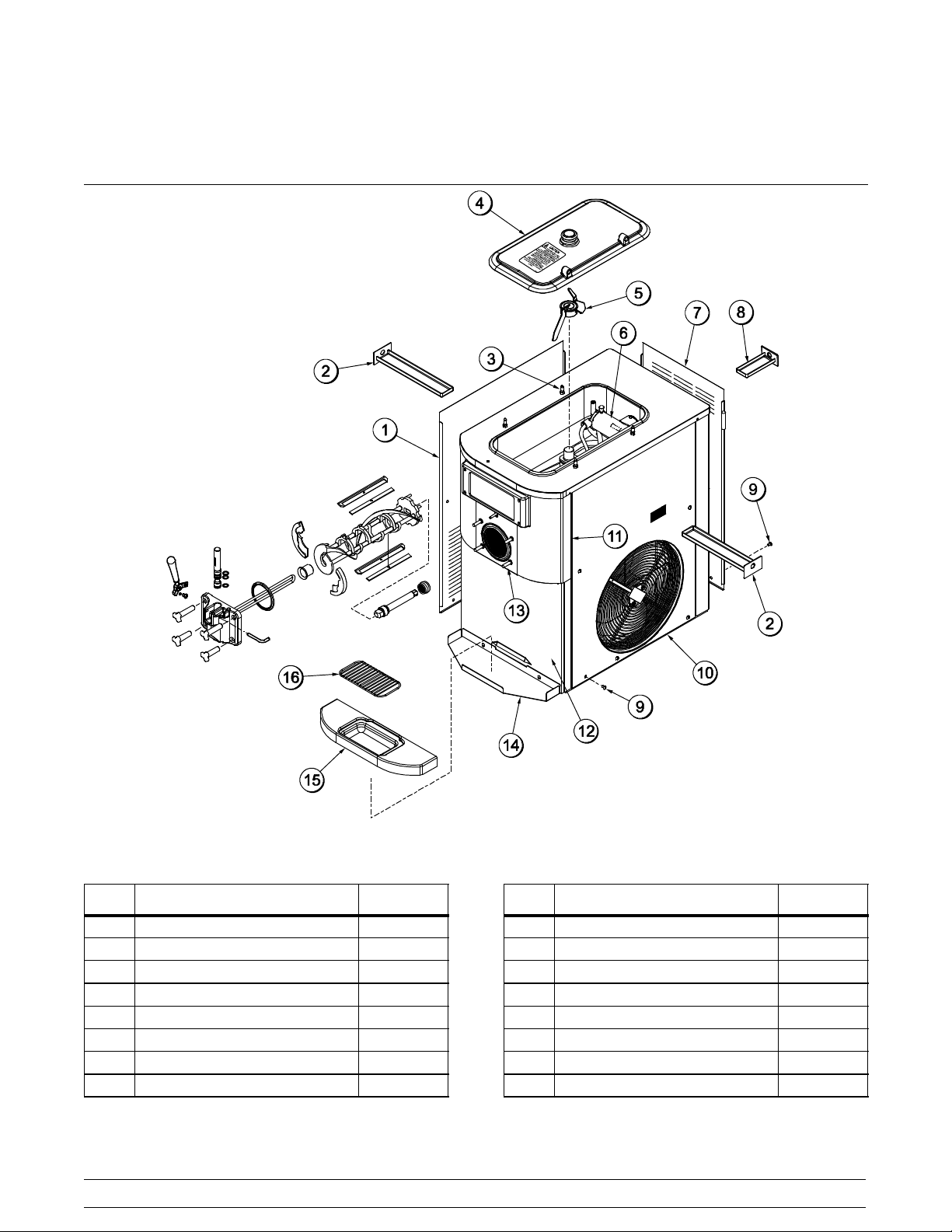
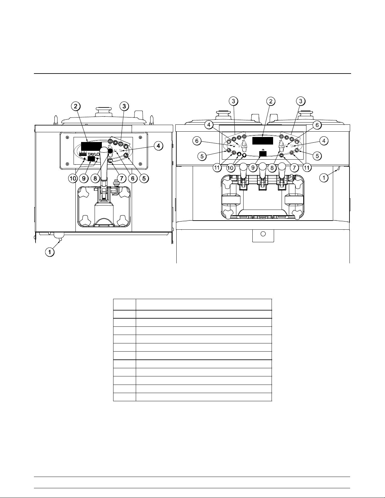
Section 4 Operator Parts Identification
Model C708
Figure 1
ITEM DESCRIPTION PART NO.
1 PANEL-SIDE-LEFT 056963
2 PAN-DRIP 11-5/8 LONG 027503
3 PIN-RETAINING-HOPPER CVR 043934
4 KIT A.-COVER-HOPPER X65368
5 BLADE A.-AGITATOR X56591
6 PUMP A.-MIX SIMPLIFIED S.S. X57029-14
7 PANEL-REAR 056077
8 PAN A.-DRIP 5 1/2” LONG X56074
Models C708 & C716 Operator Parts Identification
ITEM DESCRIPTION PART NO.
9 SCREW-1/4-20X3/8 RHM-STNLS 011694
10 PANEL A-SIDE-RIGHT X57871
11 PANEL A.-FRONT-UPPER X59423
12 PANEL A.-FRONT-LOWER X58955
13 STUD-NOSE CONE 055987
14 SHELF-TRAY-DRIP 056076
15 TRAY-DRIP 056858
16 SHIELD-SPLASH 049203
100315
7
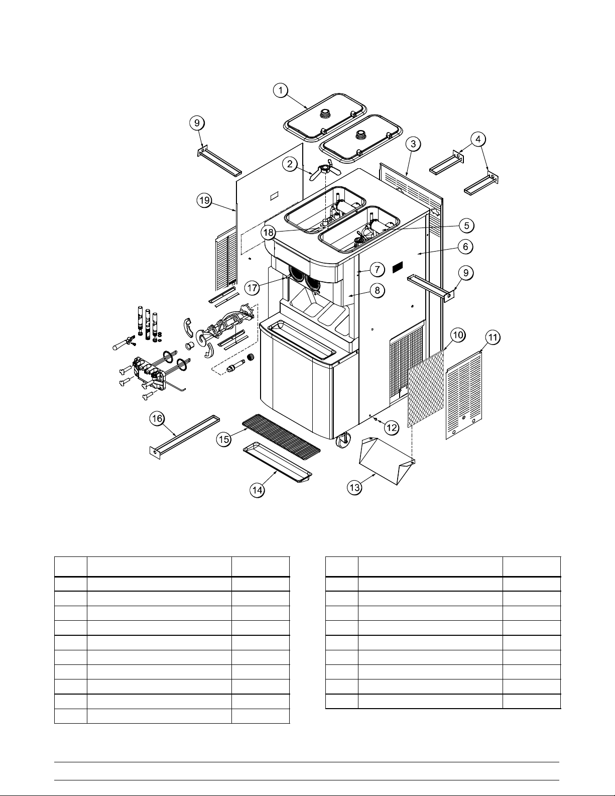
Model C716
ITEM DESCRIPTION PART NO.
1 COVER-HOPPER 053809-1
2 BLADE A.-AGITATOR X56591
3 PANEL-REAR 059916
4 PAN-DRIP 7.875 059737
5 PUMP A.-MIX SIMPLIFIED X57029-14
6 PANEL-SIDE-RIGHT 059907
7 PANEL A.-FRONT X63879
8 PANEL A.-FRONT X59836
9 PAN-DRIP 12.5 059736
10 FILTER-AIR-POLY-FLO 052779-11
061228
Figure 2
8
ITEM DESCRIPTION PART NO.
11 PANEL A.-FILTER-LOUVERED X59928
12 SCREW-1/4-20 X 3/8 RHM-SS 011694
13 DEFLECTOR 059929
14 TRAY-DRIP-19-5/8 L X 4-7/8 033812
15 SHIELD-SPLASH-WIRE-19-3/4L 033813
16 PAN-DRIP 19-1/2 LONG 035034
17 STUD-NOSE CONE 055987
18 PIN-RETAINING-HOPPER CVR 043934
19 PANEL-SIDE-LEFT 059906
Models C708 & C716Operator Parts Identification
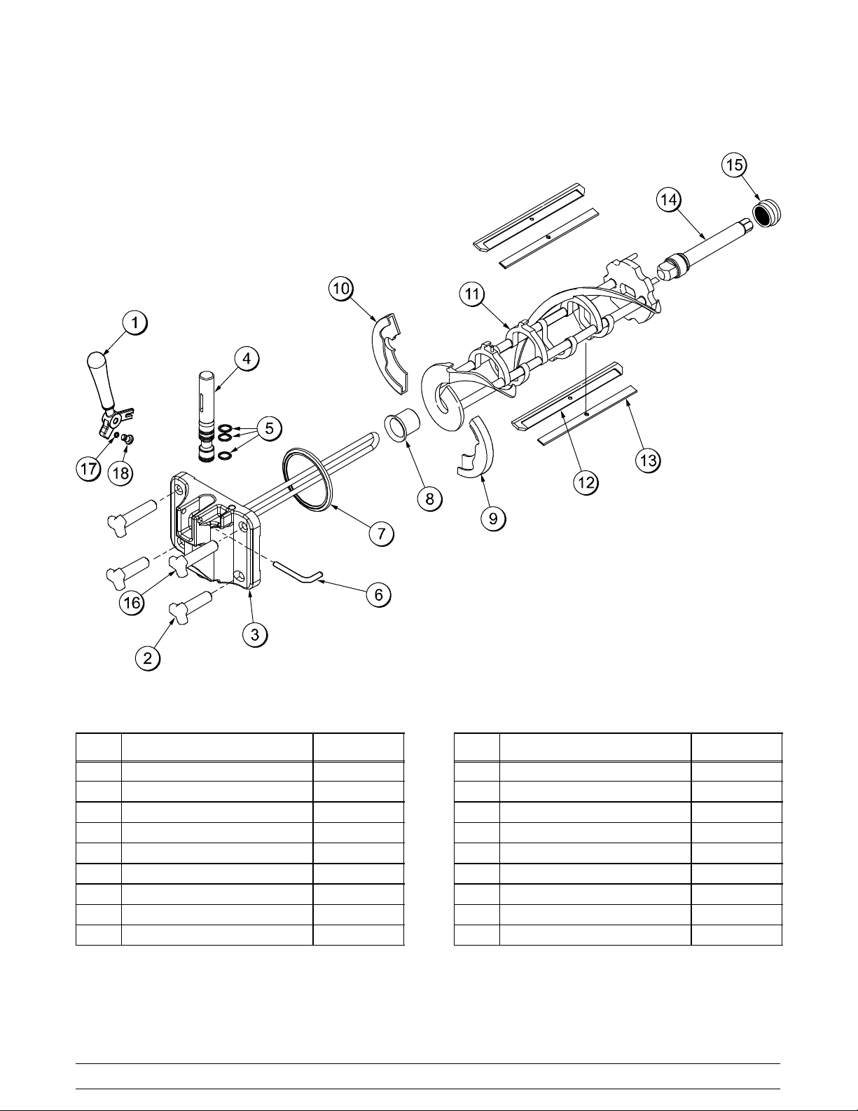
Model C708 Single Spout Door and Beater Assembly
Figure 3
ITEM DESCRIPTION PART NO.
1 HANDLE A.-DRAW-WELDED X56246
2 NUT-STUD-BLACK 2.563“ 058764
3 DOOR A.-W/BAFFLE X57332-SER
4 VALVE A.-DRAW X55820
5 O-RING-DRAW VALVE-S.S. 014402
6 PIN-HANDLE-SS 055819
7 GASKET-DOOR HT 4”-DBL 048926
8 BEARING-FRONT-SHOE 050348
9 SHOE-FRONT HELIX *REAR* 050346
Models C708 & C716 Operator Parts Identification
ITEM DESCRIPTION PART NO.
10 SHOE-FRONT HELIX *FRONT* 050347
11 BEATER A.-3.4QT-1 PIN X46231
12 BLADE-SCRAPER-PLASTIC 046235
13 CLIP-SCRAPER BLADE 7.00 046236
14 SHAFT-BEATER 056078
15 SEAL-DRIVE SHAFT 032560
16 NUT-STUD-BLACK 3.250” 058765
17 O-RING-1/4 OD X .070W 50 015872
18 SCREW-ADJUSTMT-5/16-24 056332
9
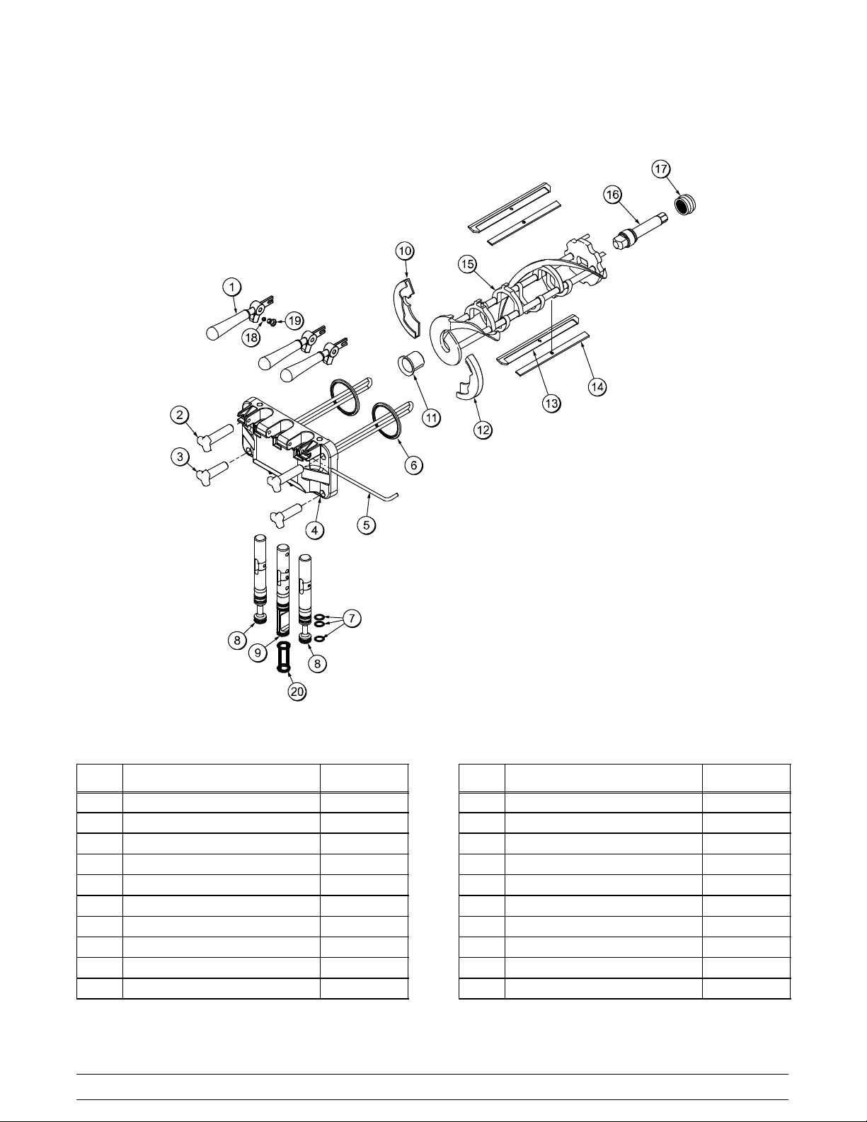
Model C716 Door and Beater Assembly
ITEM DESCRIPTION PART NO.
1 HANDLE A.-DRAW-WELDED X56421-1
2 NUT-STUD-BLACK 3.250 LONG 058765
3 NUT-STUD*BLACK 2.563 LONG 058764
4 DOOR A.-3SPT*HT*LG BAF X59923-SER
5 PIN-HANDLE-TWIN 059894
6 GASKET-DOOR HT 4”-DOUBLE 048926-1
7 O-RING--7/8 OD X .103W 014402
8 VALVE A.-DRAW X59888
9 VALVE A.-DRAW*CENTER X59890
10 SHOE-FRONT HELIX *FRONT* 050347
080805
Figure 4
10
ITEM DESCRIPTION PART NO.
11 BEARING-FRONT-SHOE 050348
12 SHOE-FRONT HELIX *REAR* 050346
13 BLADE-SCRAPER-PLAS 8-1/8L 046235
14 CLIP-SCRAPER BLADE 7.00” 046236
15 BEATER A.-3.4QT-1 PIN X46231
16 SHAFT-BEATER 032564
17 SEAL-DRIVE SHAFT 032560
18 O-RING-1/4 OD X .070W 50 015872
19 SCREW-ADJUSTMENT-5/16-24 056332
20 SEAL-DRAW VALVE H-RING 034698
Models C708 & C716Operator Parts Identification
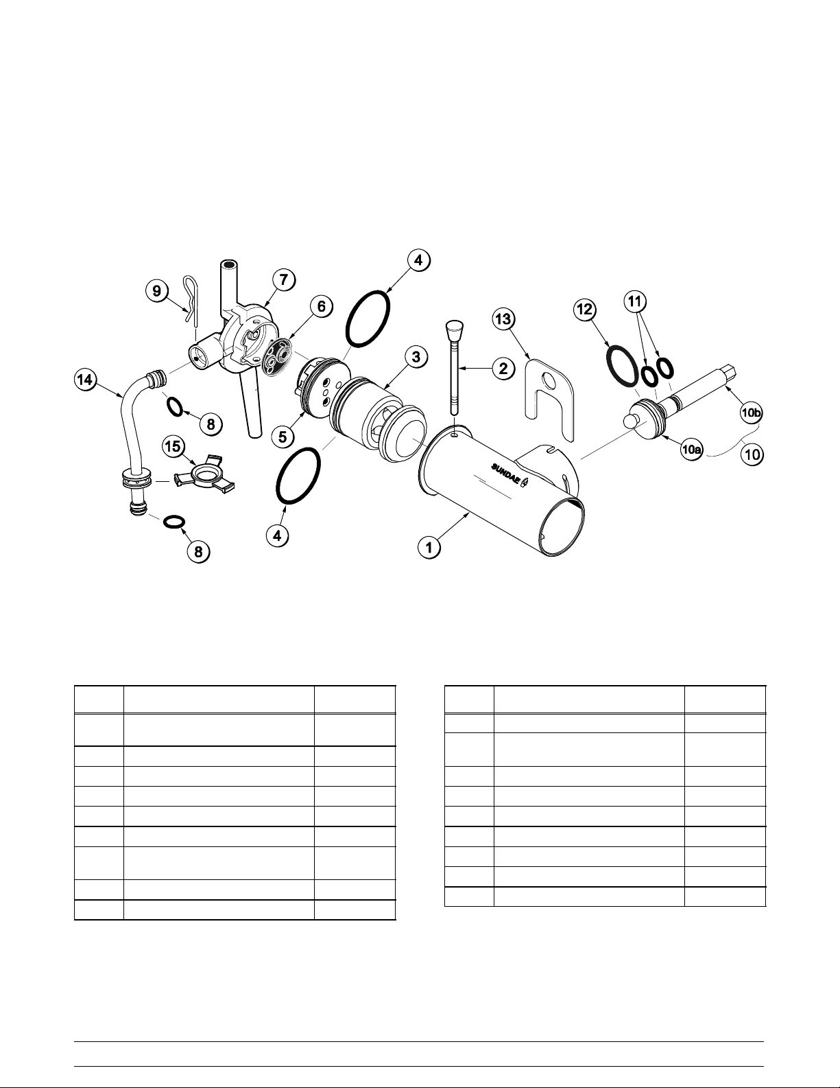
X57029-XX Pump A. - Mix Simplified (Model C708)
Figure 5
ITEM DESCRIPTION PART NO.
1-7 PUMP ASSEMBLY - MIX
SIMPLIFIED SOFT SERVE
1 CYLINDER-PUMP-HOPPER-SS 057943
2 PIN A.-RETAINING X55450
3 PISTON 053526
4 O-RING 2-1/8” OD - RED 020051
5 CAP-VALVE 056874-14*
6 GASKET-SIMPLIFIED PUMP
VALVE
7 ADAPTOR - MIX INLET 054825
8 O-RING - 11/16 OD - RED 016132
X57029-14*
053527
Models C708 & C716 Operator Parts Identification
ITEM DESCRIPTION PART NO.
9 PIN-COTTER 044731
10 SHAFT A.-DRIVE-MIX PUMP-
HOPPER
10a CRANK-DRIVE 039235
10b SHAFT-DRIVE 041948
11 O-RING - DRIVE SHAFT 048632
12 O-RING 1-3/4 008904
13 CLIP-MIX PUMP RETAINER 044641
14 TUBE A.-FEED HOPPER X56521
15 RING-CHECK .120 OD 056524
*NOTE: THE STANDARD PUMP X57029-XX IS A -14.
OVERRUN CAN BE CHANGED HIGHER OR LOWER
BY SUBSTITUTING THE CAP (056874-XX) WITH
CAPS AVAILABLE -1 THROUGH -20. THE HIGHER
THE DASH (-) NUMBER, THE HIGHER THE
OVERRUN.
11
X41947
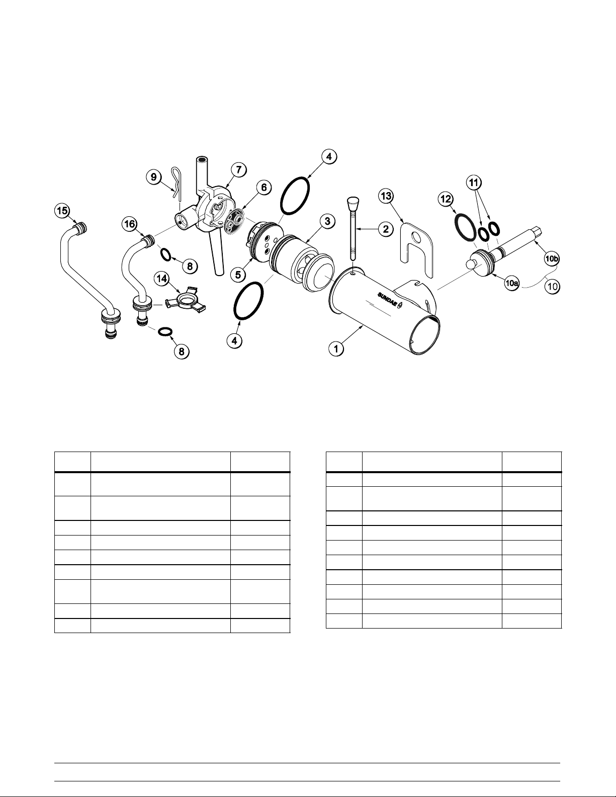
X57029-XX Pump A. - Mix Simplified (Model C716)
ITEM DESCRIPTION PART NO.
1-7 PUMP ASSEMBLY - MIX
SIMPLIFIED SOFT SERVE
1 CYLINDER-PUMP-HOPPER-
SOFT SERVE
2 PIN A.-RETAINING X55450
3 PISTON 053526
4 O-RING 2-1/8” OD - RED 020051
5 CAP-VALVE 056874-14*
6 GASKET - SIMPLIFIED PUMP
VALVE
7 ADAPTOR - MIX INLET 054825
8 O-RING - 11/16 OD - RED 016132
X57029-14*
057943
053527
Figure 6
ITEM DESCRIPTION PART NO.
9 PIN - COTTER 044731
10 SHAFT A.-DRIVE-MIX PUMP-
HOPPER
10a CRANK-DRIVE 039235
10b SHAFT-DRIVE 041948
11 O-RING - DRIVE SHAFT 048632
12 O-RING 1-3/4 008904
13 CLIP-MIX PUMP RETAINER 044641
14 RING-CHECK .120 OD 056524
15 TUBE A.-FEED-LEFT X59808
16 TUBE A.-FEED-RIGHT X59809
*NOTE: THE STANDARD PUMP X57029-XX IS -14.
OVERRUN CAN BE CHANGED HIGHER OR LOWER
BY SUBSTITUTING THE CAP (056874-XX) WITH
CAPS AVAILABLE -1 THROUGH -20. THE HIGHER
THE DASH (-) NUMBER, THE HIGHER THE
OVERRUN.
X41947
12
Models C708 & C716Operator Parts Identification
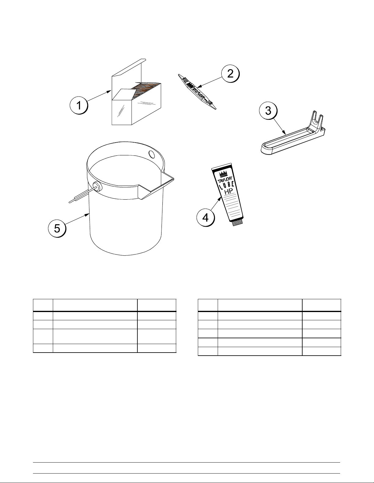
Accessories
ITEM DESCRIPTION PART NO.
1 SANITIZER-STERA SHEEN *SEE NOTE
2 TOOL-O-RING REMOVAL 048260-WHT
3 TOOL-SHAFT-DRIVE-PUMP-
HOPPER
4 LUBRICANT-TAYLOR HI-PERF 048232
057167
Figure 7
ITEM DESCRIPTION PART NO.
5 PAIL-MIX 10 QT. 013163
** KIT A.-TUNE-UP (C708) X63146
** KIT A.-TUNE-UP (C716) X49463-82
** KIT A.-PARTS TRAY (C708) X57797
** KIT A.-PARTS TRAY (C716) X67432
**Note:A sample container of sanitizer is sent with the
unit. For reorders,orderStera Sheen part no. 055492
(100 packs) or Kay-5 part no. 041082 (125 packs).
**NotShown
100520
Models C708 & C716 Operator Parts Identification
13
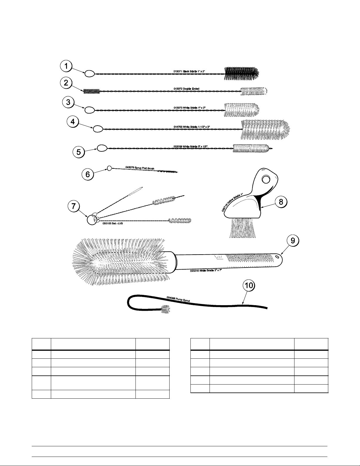
Brush A.-Package-HT X44127
ITEM DESCRIPTION PART NO.
1 BLACK BRISTLE BRUSH 013071
2 DOUBLE END BRUSH 013072
3 WHITE BRISTLE BRUSH 1” x 2” 013073
4 WHITE BRISTLE BRUSH
1-1/2”x 3”
5 WHITE BRISTLE BRUSH 1/2 x 3 033059
100507
014753
Figure 8
14
ITEM DESCRIPTION PART NO.
6 BRUSH-SYRUP PORT 045079
7 BRUSH SET (3) 050103
8 YELLOW BRISTLE BRUSH 039719
9 WHITE BRISTLE BRUSH 3” x 7” 023316
10 PUMP SPOUT BRUSH 054068
Models C708 & C716Operator Parts Identification
Section 5 Important: To the Operator
C708 C716
Figure 9
ITEM DESCRIPTION
1 POWER SWITCH
2 LIQUID CRYSTAL DISPLAY
3 KEYPADS
4 MIX OUT INDICATOR
5 STANDBY INDICATOR
6 MIX LOW INDICATOR
7 SELECT KEY
8 SERVICE MENU KEY
9 BRUSH CLEAN COUNTER
10 ARROW KEY(S)
11 TOPPING HEATER KEY
Models C708 & C716 Important: To the Operator
15
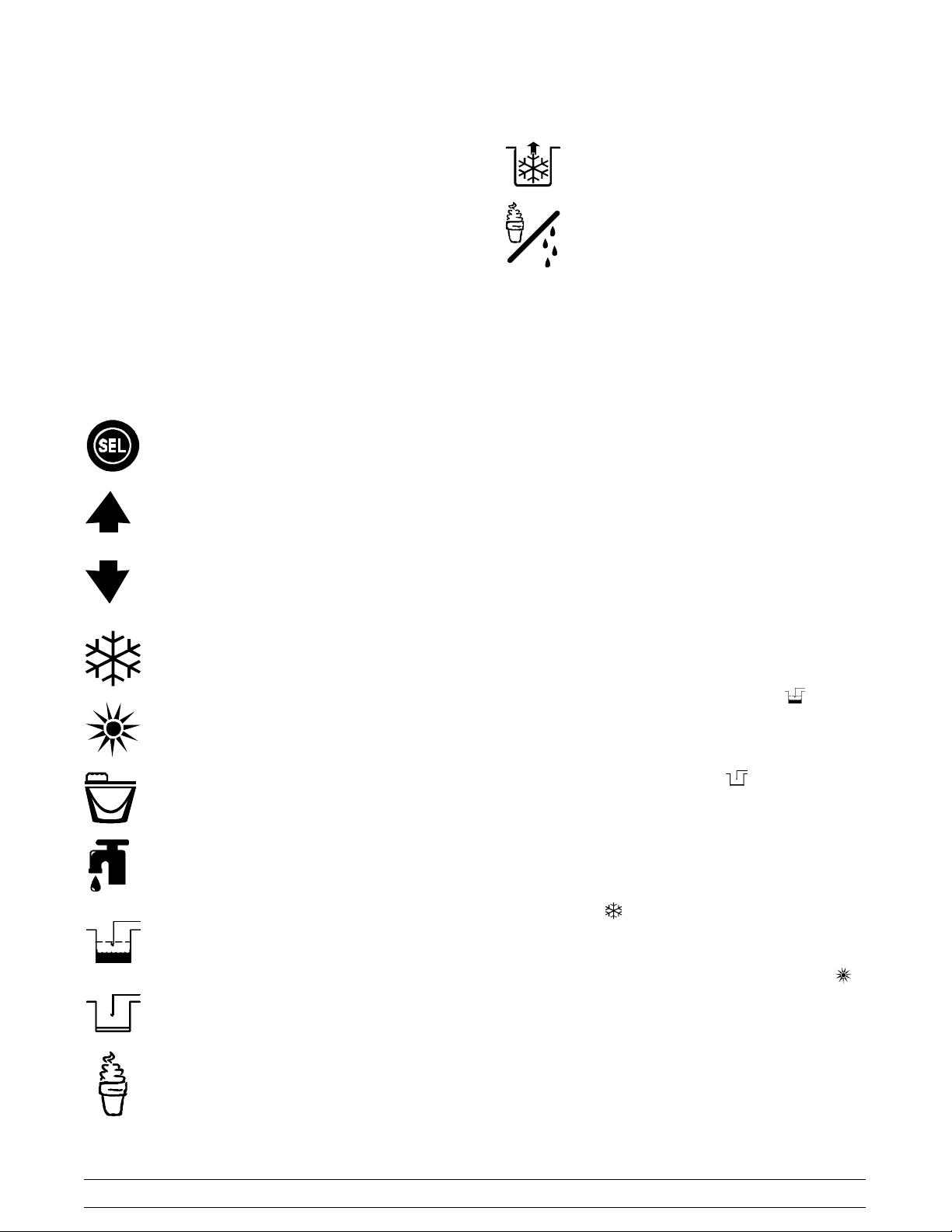
Symbol Definitions
=MIXPUMP
To better communicate in the International arena,
symbols have replaced words on many of our
operator switches, function, and fault indicators.
Your Taylor equipment is designed with these
International symbols.
The following chart identifies the symbol definitions.
= SELECT
= UP ARROW
= DOWN ARROW
=AUTO
= STANDBY
Power Switch
When placed in the ON position, the power switch
allows control panel operation.
Fluorescent Display
The fluorescent display is located on the front
control panel. During normal operation the display is
blank. The display is used to show menu options
and notifies the operator if a fault is detected. On
International models, the display will indicate the
temperature of the mix in the hopper.
Indicator Lights
= HEAT CYCLE
= WASH (Model C708)
= WASH (Model C716)
=MIXLOW
= MIX OUT
= MENU DISPLAY
MIX LOW - When the MIX LOW symbol is
illuminated, the mix hopper has a low supply of mix
and should be refilled as soon as possible.
MIX OUT - When the MIX OUT
illuminated, the mix hopper has been almost
completely exhausted and has an insufficient supply
of mix to operate the freezer. At this time, the AUTO
mode is locked out and the freezer will be placed in
the STANDBY mode. To initiate the refrigeration
system, add mix to the mix hopper and touch the
AUTO symbol
begin operation.
HEAT MODE - When the HEAT MODE symbol
is illuminated, the freezer is in the process of a heat
cycle.
BRUSH CLEAN COUNTER - When the BRUSH
CLEAN COUNTER display has counted down to “1”,
the machine must be disassembled and brush
cleaned within 24 hours.
. The freezer will automatically
symbol is
100507
16
Models C708 & C716Important: To the Operator
Reset Mechanism
The reset button is located in the service panel on
the left side of the C708. The reset buttons are
located in the back panel of the C716. A reset button
protects the beater motor from an overload
condition. Should an overload occur, the reset
mechanism will trip. To properly reset the freezer
place the power switch in the OFF position. Press
the reset button firmly. Turn the power switch to the
ON position. Touch the WASH symbol
observe the freezer's performance.
WARNING: Do not use metal objects to
press the reset button. Failure to comply may
result in severe personal injury or death.
and
Figure 10
Operating Screen Descriptions
If the beater motor is turning properly, touch the
WASH symbol
AUTO symbol
freezer shuts down again, contact your authorized
service technician.
to cancel the cycle. Touch the
to resume normal operation. If the
Air/Mix Pump Reset Mechanism
This reset button protects the pump from an
overload condition. Should an overload occur, the
reset mechanism will trip. To reset the pump, press
the reset button firmly.
WARNING: Do not use metal objects to
press the reset button. Failure to comply may
result in severe personal injury or death.
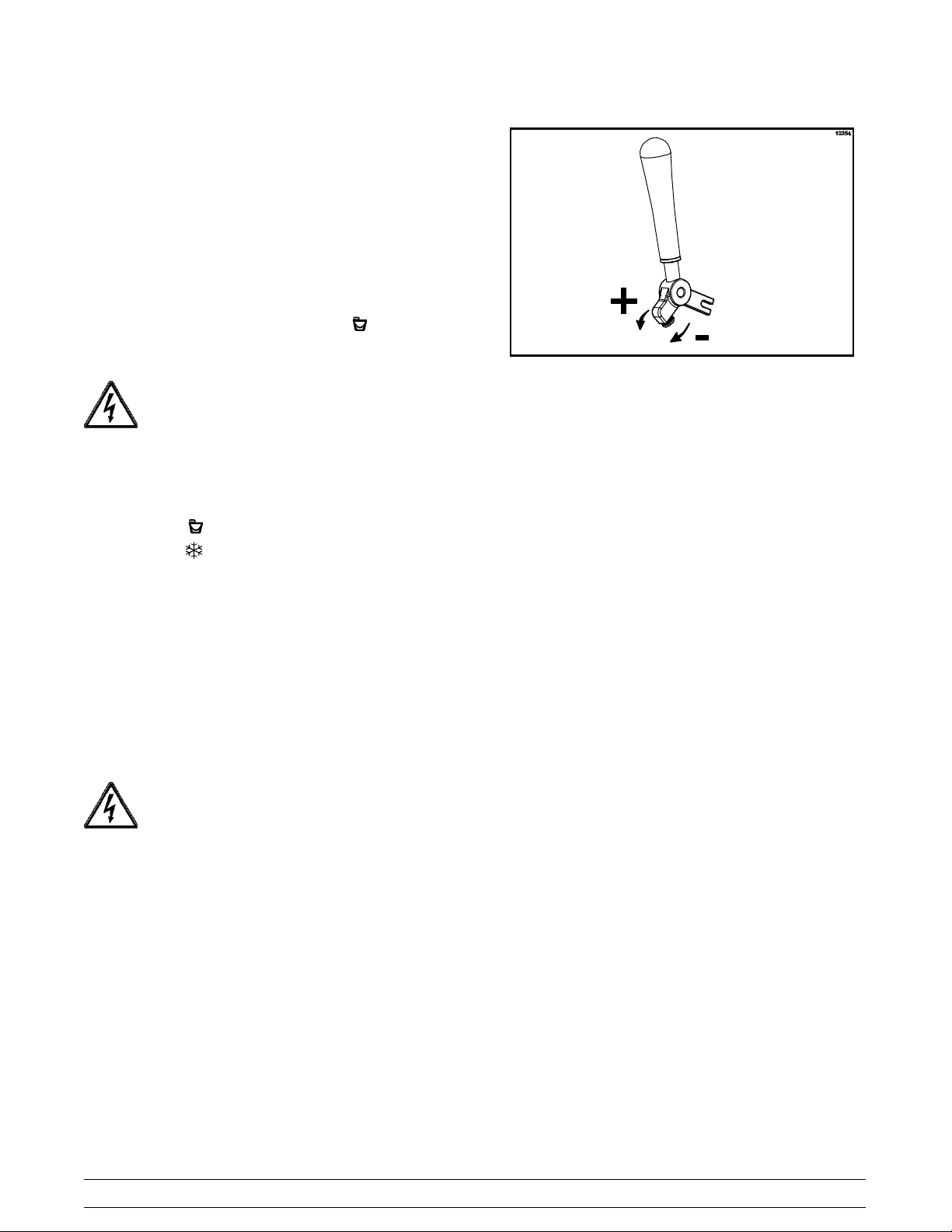
Adjustable Draw Handle
The fluorescent display located in the center of the
control panel is normally blank during the daily
operation of the machine. The display is activated
when the SEL symbol or the Manager's Menu is
selected. The display screen will also alert the
operator of specific faults detected by the control.
Note: The displays illustrated in this section are
those seen on the Models C708/C709. The Model
C716/C717 versions may vary slightly.
Power Up Memory (Initializin g)
The seven segment display should display “00”
during the initializing sequence.
When the machine is powered, the control system
will initialize to perform a system check. The screen
will display “INITIALIZING”. There will be four types
of data the system will check: LANGUAGE,
SYSTEM DATA, CONFIG DATA, and LOCKOUT
DATA.
Language Initialization
These units feature an adjustable draw handle(s) to
provide the best portion control, giving a better,
consistent quality to your product and controlling
costs. The draw handle(s) should be adjusted to
provide a flow rate of 5 to 7-1/2 oz. (142 to 213 g.)
of product by weight per 10 seconds. To INCREASE
the flow rate, turn the screw CLOCKWISE. To
DECREASE the flow rate, turn the screw
COUNTERCLOCKWISE . (See Figure 10.)
Models C708 & C716 Important: To the Operator
The UVC platform supports multiple languages by
keeping specific strings in battery backed RAM.
After power-up or a CPU reset, the strings are
tested to see if the language strings are present and
not corrupted. If the strings are present and not
corrupted, initialization continues. Otherwise, the
operator is prompted to select a language. While
language strings are being checked for integrity, the
following screen is displayed.
050628
17

Initializing
Language
Note: If there is a language initialization fault, the
machine will force a language selection prior to the
initializing sequence. The standard menu LED's
should light, as if it were in a menu. If a language
has been selected, the unit is powered down, the
machine should not ask for a language unless there
is another language initialization fault. English is the
factory default setting.
System Data
The system will continue to operate in its previous
mode but according to default settings.
Lockout Data
Lockout data is protected separately from the rest of
the data in the memory. While the Lockout Data is
being checked, the following screen is displayed.
Initializing
Lockout Data
System data is protected separately from the rest of
the data in memory. System data includes variables
that change frequently such as the mode the
machine is in, lockout status, serving counters, fault
codes, and others. While System Data is being
checked the following screen is displayed.
Initializing
System Data
If the System Data is corrupted, the machine is set
to OFF, the serving counters are set to zero, and the
faults are cleared. A “SYSTEM CRC ERR” fault is
set and displayed on the VFD. An acknowledgement
(SEL key) is required.
Configuration Data
Configuration data is separate from the rest of the
data in the memory. Configuration data is
information entered through operator and service
menus. While Configuration Data is being checked
the following screen is displayed.
Initializing
Config Data
If Lockout Data is corrupted, all lockout history data
is cleared. A “LOCKOUT CRC ERR” fault is
displayed.
After the memory integrity has been tested, the
Safety Timeout screen will be displayed.
Heat Cycle Data
Heat cycle data is checked separately from the rest
of the data in memory. Each individual Heat Cycle
Data record is monitored for corruption individually.
At the start of a heat cycle, the next Heat Cycle data
record is cleared and data for the heat cycle is
writtentoit.ThecurrentHeatCycleDatais
displayed as the first heat cycle record in the HEAT
CYCLE DATA menu option.
The heat cycle data records are checked for integrity
when the record is accessed, presently only through
the HEAT CYCLE DATA menu option. (For
additional Heat Cycle Data information,
see page 28.)
Once the system has initialized, the number of days
until brush cleaning is required is indicated on the
control panel. The SAFETY TIMEOUT screen will
be displayed with the alarm on for 60 seconds or
until any control symbol is touched.
If Configuration data is corrupted, all user and
service settings are set to defaults. A “CONFIG
CRC ERR” fault is set and displayed on the VFD.
050628
18
SAFETY TIMEOUT
ANY KEY ABORTS
Models C708 & C716Important: To the Operator
Power Switch OFF
After the safety timeout has been completed and the
power switch is OFF, the following screen is
displayed.
POWER SWITCH OFF
-=-=-=-=-=UNIT CLEANED
Power Switch ON
When the power switch is placed in the ON position,
the control panel touch keys become operative. The
fluorescent display will be either blank or indicate
that the unit has been cleaned.
UNIT CLEANED
Use the up or down arrow symbol to move the
cursor to “YES”. Touch the SEL symbol to
immediately start a heat cycle.
Note: The machine must be in AUTO or STANDBY
and have sufficient mix in the hopper before the
machine can successfully enter the HEAT mode of
operation.
Heat Cycle
The HEAT symbol on the control panel is illuminated
throughout the heat treatment cycle. Two warning
messages will be displayed on the screen. “DO NOT
DRAW” will be displayed when the mix temperature
is below 130°F (54.4°C).
DO NOT DRAW
When the temperature of the mix is above 130°F
(54.4°C) the screen will display a message
indicating that HOT PRODUCT is in the machine.
International M odels Only:
Some International models will continuously display
the temperature of the mix hopper when the power
switch is in the ON position.
HOPPER 21.0
UNIT CLEANED
If the control is set for international configuration, the
following screen will appear when the heat symbol is
touched.
ARE YOU SURE
>Yes
No
HOT PRODUCT
DO NOT attempt to draw product or
disassemble the unit during the HEAT cycle. The
product is hot and under extreme pressure.
In the HEAT cycle, the mix temperature in the
hopper and freezing cylinder must be raised to
151°F (66.1°C) within 90 minutes.
When the heating phase is complete, the freezer
goes into the holding phase of the cycle. The holding
phase will keep the temperature above 151°F
(66.1°C) for a minimum of 35 minutes.
The final phase of the heat treatment cycle is the
cooling phase. The freezer must cool the mix below
41°F (5°C) within 90 minutes.
When the entire heat cycle has been completed, the
HEAT symbol will no longer be illuminated. The
machine will enter the STANDBY mode (STANDBY
symbol illuminates). The machine can be placed in
AUTO or left in STANDBY.
050628
Models C708 & C716 Important: To the Operator
19

To comply with health codes, heat treatment system
freezers must complete a heat treatment cycle
daily, and must be disassembled and brush cleaned
a minimum of every 14 days. Brush cleaning is the
normal disassembly and cleaning procedure found in
the Operator Manual. Failure to follow these
guidelines will cause the control to lock the freezer
out of the AUTO mode.
If the Heat Treatment Cycle fails, the screen will
display a failure message and return the freezer to
the STANDBY mode.
Always comply with local guidelines for the
maximum number of days allowed between brush
clean cycles.
Freezer Locks
2. The following screen will display if there has
been a thermistor failure (freezing cylinder or
hopper) during the heat treatment process.
SYSTEM FAULT
FREEZER LOCKED
SERVICE REQ'D
> BRUSH CLEAN
Touching the SEL symbol will indicate which
thermistor caused the Hard Lock.
There are two types of freezer lock conditions that
can occur: Hard Lock or Soft Lock. A Hard Lock
requires the machine be disassembled and brush
cleaned. A Soft Lock can be corrected by either
disassembling and brush cleaning the machine, or
by starting another heat treatment cycle.
Hardlock
There are two causes of a hard lock failure. The
freezer will hardlock if either the Brush Clean Timer
has elapsed or if a Thermistor Failure (Freezing
Cylinder or Hopper) occurred during a Heat cycle.
1. The following screen will be displayed if a Brush
Clean Cycle Time has occurred.
BRUSH CLEAN TIMEOUT
FREEZER LOCKED
CLEANING REQ'D
> BRUSH CLEAN
Touching the SEL symbol will display the following
screen.
HOPPER THERM BAD
FREEZER LOCKED
If the machine has hard locked and an attempt is
made to enter AUTO, the machine will enter the
STANDBY mode and display the following message.
FREEZER LOCKED
To restore the message that identified the reason for
the hard lock, turn the power switch OFF for five
seconds and then return the power switch to the ON
position. The original message with the reason for
the Hard Lock will be displayed.
080222
FREEZER LOCKED
The FREEZER LOCKED message will remain on
the display until the brush clean requirements are
fulfilled. The freezer must be disassembled in order
to activate the five minute timer on the display
screen. Once the timer counts down to zero, the
lockout is cleared.
20
Models C708 & C716Important: To the Operator
Soft Lock
If a heat treatment cycle has not been initiated within
the last 24 hours, a soft lock failure will occur. A soft
lock allows the operator to correct the cause of the
soft lock. The operator has the option of either
starting another heat cycle or brush cleaning the
machine. When a soft lock occurs, the machine will
go into the STANDBY mode. The following message
is displayed on the screen. The reason for the soft
lock is indicated on the second line.
A soft lock can also occur any time during operation
when the hopper or freezing cylinder temperature
rises above 59°F (15°C), the temperature rises and
remains above 45°F(7°C) for more than one hour, or
the temperature rises and remains above 41°F(5°C)
for more than four hours.
If a PRODUCT OVER TEMPERATURE condition
occurs during operation, the following screen will
appear.
NO HEAT CYCLE START
REASON
> HEAT CYCLE
BRUSH CLEAN
If the reason for the soft lock has been corrected,
selecting HEAT CYCLE initiates a Heat Cycle
immediately. Selecting BRUSH CLEAN when the
previous message is displayed will hard lock the
machine and brush cleaning will be necessary.
Following are the variable messages for soft lock
failures that appear on the second line of the screen.
POWER SWITCH OFF
Power switch was in the
OFF position.
MIX OUT PRESENT There was a mix out
condition present.
AUTO OR STANDBY
OFF
The machine was not in
the AUTO or STANDBY
mode.
NO HEAT CYCLE
TRIED
A heat treatment cycle
was not attempted in
the last 24 hours.
(AUTO HEAT TIME
was advanced or a power loss was experienced
at the time the cycle
was to occur.)
If the following screen appears, a soft lock has
occurred during the heat treatment cycle.
PRODUCT OVER TEMP
> HEAT CYCLE
BRUSH CLEAN
When one of these messages appears, automatic
freezer operation cannot take place until the freezer
is disassembled and brush cleaned, or has
completed a heat treatment cycle.
Once the freezer is unlocked by starting a heat
treatment cycle the HEAT symbol will illuminate and
the following message will be displayed on the
screen.
DO NOT DRAW
If BRUSH CLEAN is selected to clear the lockout by
brush cleaning the machine, the FREEZER
LOCKED message will remain on the display until
the brush clean requirements are fulfilled. The
freezer must be disassembled in order to activate
the five minute timer on the display screen. Once
the timer counts down to zero, the lockout is
cleared.
HEAT TREAT FAILURE
FREEZER LOCKED
> HEAT CYCLE
BRUSH CLEAN
Models C708 & C716 Important: To the Operator
21
FREEZER LOCKED
050628
 Loading...