

Page 1

Models 441 & 444
Shake Freezers
Operating Instructions
029405-M
6/97
Page 2

Complete this page for quick reference when service is required:
Taylor Distributor:
Address:
Phone:
Service:
Parts:
Date of Installation:
Information found on the data label:
Model Number:
Serial Number:
Electrical Specs: Voltage Cycle
Phase
Maximum Fuse Size: A
Minimum Wire Ampacity: A
E June, 1997 Taylor
All rights reserved.
029405-M
Taylor Company
The word Taylor and the Crown design
are registered trademarks in the United States
of America and certain other countries.
a division of Carrier Commercial Refrigeration, Inc.
750 N. Blackhawk Blvd.
Rockton, IL 61072
Page 3

Table of Contents
Section 1 To the Installer 1............................................
Installer Safety 1........................................................
Site Preparation 1.......................................................
Air Cooled Units 2.......................................................
Water Connections (Water Cooled Units Only) 2............................
Electrical Connections 2.................................................
Check Out 3............................................................
Refrigerant 3...........................................................
Section 2 To the Operator 4...........................................
Compressor Warranty Disclaimer 4.......................................
Section 3 Safety 5....................................................
Section 4 Operator Parts Id en t ificatio n 7...............................
Model 441 7............................................................
Model 444 8............................................................
Models 441 & 444 Door Assembly 9.......................................
Accessories 10..........................................................
Section 5 Important: To the Operator 11.................................
Indicator Light “Mix Low” 11...............................................
Symbol Definitions 11....................................................
Control Switch 11........................................................
Reset Button 11.........................................................
Thermistor Control 12....................................................
Separate Hopper Refrigeration System (SHR) 12............................
Table of Contents Models 441 & 444
Page 4

Table of Contents -- Page 2
o
______________________________________________________________________________
Section 6 Operating Procedures 13.....................................
Assembly 13............................................................
Sanitizing 15............................................................
Priming 17..............................................................
Closing Procedure 17....................................................
Draining Product From the Freezing Cylinder 18.............................
Rinsing 18..............................................................
Cleaning 18.............................................................
Disassembly 19..........................................................
Brush Cleaning 19.......................................................
Section 7 Important: Operator Checklist 20..............................
During Cleaning and Sanitizing 20.........................................
Troubleshooting Bacterial Count 20........................................
Regular Maintenance Checks 20...........................................
Winter Storage 21........................................................
Section 8 Troubleshooting Guide 22....................................
Section 9 Parts Replacement Schedule 25...............................
Section 10 Parts List 26.................................................
Wiring Diagrams 32......................................................
Note: Continuing research results in steady improvements; therefore, information
in this manual is subject to change without notice.
E June, 1997 Taylor
All rights reserved.
029405-M
Taylor Company
The word Taylor and the Crown design
are registered trademarks in the United States
of America and certain other countries.
a division of Carrier Commercial Refrigerati
750 N. Blackhawk Blvd.
Rockton, IL 61072
Models 441 & 444
Table of Contents
Page 5

Section 1 To the Installer
The following are general installation instructions. For
complete installation details, please see the check out
card.
cause severe injuries.
Installer Safety
This unit has many sharp edges that can
In all areas of the world, equipment should be
installed in accordance with existing local codes.
Please contact your local authorities if you have any
questions.
Care should be taken to ensure that all basic safety
practices are followed during the installation and
servicing activities related to the installation and
service of Taylor equipment.
S Only authorized Taylor service personnel
should perform installation and repairs on
the equipment.
S Authorized service personnel should consult
OSHA Standard 29CFRI910.147 or the
applicable code of the local area for the
industry standards on lockout/tagout
procedures before beginning any installation
or repairs.
S Authorized service personnel must ensure
that the proper PPE is available and worn
when required during installation and
service.
S Authorized service personnel must remove
all metal jewelry, rings, and watches before
working on electrical equipment.
The main power supply(s) to the freezer must
be disconnected prior to performing any repairs.
Failure to follow this instruction may result in personal
injury or death from electrical shock or hazardous
moving parts as well as poor performance or damage
to the equipment.
Note:Allrepairsmustbeperformedbyan
authorized Taylor Service Technician.
Site Preparation
Review the area the unit is to be installed in before
uncrating the unit, making sure that all possible
hazards the user or equipment may come into have
been addressed.
For Indoor Use Only: This unit is designed to operate
indoors, under normal ambient temperatures of
70_-75_F(21_-24_C). The freezer has successfully
performed in high ambient temperatures of
104_(40_C) at reduced capacities.
This unit must NOT be installed in an area
where a water jet or hose can be used. NEVER use a
water jet or hose to rinse or clean the unit. Failure to
follow this instruction may result in electrocution.
This unit must be installed on a level surface
to avoid the hazard of tipping. Extreme care should be
taken in moving this equipment for any reason. Two or
more persons are required to safely move this unit.
Failure to comply may result in personal injury or
equipment damage.
Uncrate the unit and inspect it for damage. Report any
damage to your Taylor Distributor.
This piece of equipment is made in the USA and has
USA sizes of hardware. All metric conversions are
approximate and vary in size.
080924
Models 441 & 444 To th e Installer
1
Page 6
Air Cooled Units
DO NOT obstruct air intake and discharge openings:
existing local codes. Please contact your local
authorities.
Air cooled units require a minimum of 3” (76 mm) of
clearance around all sides of the freezer to allow for
adequate air flow across the condensers. Install the
deflector provided to prevent recirculation of warm air.
Failure to allow adequate clearance can reduce the
refrigeration capacity of the freezer and possibly
cause permanent damage to the compressor.
Water Connections
(Water Cooled Units Only)
An adequate cold water supply must be provided with
a hand shut--off valve. On the underside rear of the
base pan, two 3/8” I.P.S. (for single head units) or two
1/2” I.P.S. (for double head units) water connections
for inlet and outlet have been provided for easy
hook--up. 1/2” inside diameter water lines should be
connected to the machine. (Flexible lines are
recommended, if local codes permit.) Depending on
local water conditions, it may be advisable to install a
water strainer to prevent foreign substances from
clogging the automatic water valve. There will be only
one water “in” and one water “out” connection for both
single head and double head units. DO NOT install a
hand shut--off valve on the water “out” line! Water
should always flow in this order: first, through the
automatic water valve; second, through the
condenser; and third, through the outlet fitting to an
opentrapdrain.
A back flow prevention device is required
on the incoming water connection side. Please
refer to the applicable National, State, and local codes
for determining the proper configuration.
Electrical Connections
In the United States, this equipment is intended to be
installed in accordance with the National Electrical
Code (NEC), ANSI/NFPA70-1987. The purpose of the
NEC code is the practical safeguarding of persons and
property from hazards arising from the use of
electricity. This code contains provisions considered
necessary for safety. In all other areas of the world,
equipment should be installed in accordance with the
FOLLOW YOUR LOCAL ELECTRICAL CODES!
CAUTION: THIS EQUIPMENT MUST BE
PROPERLY GROUNDED! FAILURE TO DO SO
CAN RESULT IN SEVERE PERSONAL INJURY
FROM ELECTRICAL SHOCK!
This unit is provided with an equipotential
grounding lug that is to be properly attached to the rear
of the frame by the authorized installer. The installation
location is marked by the equipotential bonding
symbol (5021 of IEC 60417-1) on both the removable
panel and the equipments frame.
S Stationary appliances which are not
equipped with a power cord and a plug or
another device to disconnect the appliance
from the power source must have an all-pole
disconnecting device with a contact gap of
at least 3mm installed in the external
installation.
S Appliances that are permanently connected
to fixed wiring and for which leakage
currents may exceed 10 mA, particularly
when disconnected or not used for long
periods, or during initial installation, shall
have protective devices such as a GFI, to
protect against the leakage of current,
installed by the authorized personnel to the
local codes.
S Supply cords used with this unit shall be
oil-resistant, sheathed flexible cable not
lighter than ordinary polychloroprene or
other equivalent synthetic
elastomer-sheathed cord (Code designation
60245 IEC 57) installed with the proper cord
anchorage to relieve conductors from strain,
including twisting, at the terminals and
protect the insulation of the conductors from
abrasion.
080924
To th e Installer
2
Models 441 & 444
Page 7
Check Out
Once the unit is installed, it is advisable to check the
following controls and mechanical operations of the
freezer and to make any necessary adjustments. If
applicable, repeat these checks for the second
freezing cylinder on double head units.
Controls
Place the control switch in the “AUTO” position. The
main refrigeration system will operate (compressor,
beater motor, and the condenser fan). The dial light
and the mix low indicator will be illuminated.
Refrigerant
In consideration of our environment, T aylor
proudly uses only earth friendly HFC refrigerants. The
HFC refrigerant used in this unit is R404A. This
refrigerant is generally considered non-toxic and
non-flammable, with an Ozone Depleting Potential
(ODP) of zero (0).
However, any gas under pressure is potentially
hazardous and must be handled with caution.
NEVER fill any refrigerant cylinder completely with
liquid. Filling the cylinder to approximately 80% will
allow for normal expansion.
Refrigerant liquid sprayed onto the skin may
cause serious damage to tissue. Keep eyes and skin
protected. If refrigerant burns should occur, flush
immediately with cold water. If burns are severe, apply
ice packs and contact a physician immediately.
Figure 1
If the freezer is water cooled, the automatic water
valve will begin to open and cold water will flow into the
condenser. This will remove heat from the refrigerant.
As the water flows into the open trap drain, it should be
warm to the touch. Place the control switch in the
“OFF” position.
Beater Rotation
Beater rotation must be clockwise as viewed
looking into the freezing cylinder.
Note: The following procedures must be
performed by an authorized Taylor service
technician.
To correct rotation on a three--phase unit, interchange
any two incoming power supply lines at the freezer
main terminal block only. To correct rotation on a
single--phase unit, exchange leads inside the beater
motor. (Follow the diagram printed on the motor.)
Electrical connections are made directly to the
terminal block provided in the main control box located
behind the service panel.
Taylor reminds technicians to be cautious of
government laws regarding refrigerant recovery,
recycling, and reclaiming systems. If you have any
questions regarding these laws, please contact the
factory Service Department.
WARNING: R404A refrigerant used in
conjunction with polyolester oils is extremely moisture
absorbent. When opening a refrigeration system, the
maximum time the system is open must not exceed 15
minutes. Cap all open tubing to prevent humid air or
water from being absorbed by the oil.
080924
Models 441 & 444 To th e Installer
3
Page 8

Section 2 To the Operator
The freezer you have purchased has been carefully
engineered and manufactured to give you dependable
operation. The T aylor freezer, when properly operated
and cared for, will produce a consistent quality product.
Like all mechanical products, this machine will require
cleaning and maintenance. A minimum amount of care
and attention is necessary if the operating procedures
outlined in this manual are followed closely.
This Operator’s Manual should be read before
operating or performing any maintenance on your
equipment.
Your Taylor freezer will NOT eventually compensate
and correct for any errors during the set--up or filling
operations. Thus, the initial assembly and priming
procedures are of extreme importance. It is strongly
recommended that all personnel responsible for the
equipment’s operation review these procedures in
order to be properly trained and to makesure that there
is no confusion.
In the event that you should require technical
assistance, please contact your local authorized
Taylor Distributor.
Note: Warranty is valid only if the parts are authorized
Taylor parts, purchased from an authorized Taylor
Distributor, and the required service work is provided
by an authorized T aylor service technician. Taylor
reserves the right to deny warranty claims on
equipment or parts if non--approved parts or
refrigerant were installed in t he machine, system
modifications were performed beyond factory
recommendations, or it is determined that the failure
was caused by neglect or abuse.
Note: Constant research results in steady
improvements; therefore, information in this
manual is subject to change without notice.
For additional information regarding applicable local
laws, please contact the municipal facility and/or local
distributor.
Compressor Warranty Disclaimer
The refrigeration compressor(s) on this machine are
warranted for the term indicated on the warranty card
accompanying this machine. However, due to the
Montreal Protocol and the U.S. Clean Air Act
Amendments of 1990, many new refrigerants are
being tested and developed, thus seeking their way
into the service industry. Some of these new
refrigerants are being advertised as drop--in
replacements for numerous applications. It should be
noted that, in the event of ordinary service to this
machine’s refrigeration system, only the refrigerant
specified on the affixed data label should be used.
The unauthorized use of alternate refrigerants will void
your compressor warranty . It will be the owner’s
responsibility to make this fact known to any technician
he employs.
It should also be noted that Taylor does not warrant the
refrigerant used in its equipment. For example, if the
refrigerant is lost during the course of ordinary service
to this machine, Taylor has no obligation to either
supply or provide its replacement either at billable or
unbillable terms. Taylor does have the obligation to
recommend a suitable replacement if the original
refrigerant is banned, obsoleted, or no longer available
during the five year warranty of the compressor.
If the crossed out wheeled bin symbol is
affixed to this product, it signifies that this product is
compliant with the EU Directive as well as other similar
legislation in effect after August 13, 2005. Therefore,
it must be collected separately after its use is
completed, and cannot be disposed as unsorted
municipal waste.
The user is responsible for returning the product to the
appropriate collection facility, as specified by your local
code.
080924
To th e Operator
Taylor will continue to monitor the industry and test
new alternates as they are being developed. Should a
new alternate prove, through our testing, that it would
be accepted as a drop-- in replacement, then the above
disclaimer would become null and void. To find out the
current status of an alternate refrigerant as it relates to
your compressor warranty, call the local Taylor
Distributor or the Taylor Factory. Be prepared to
provide the Model/Serial Number of the unit in
question.
4
Models 441 & 444
Page 9
Section 3 Safety
We at Taylor Company are concerned about the safety
of the operator when he or she comes in contact with
the freezer and its parts. Taylor has gone to extreme
efforts to design and manufacture built--in safety
features to protect both you and the service technician.
As an example, warning labels have been attached to
the freezer to further point out safety precautions to the
operator.
IMPORTANT -- Failure to adhere to the
following safety precautions may result in severe
personal injury or death. Failure to comply with
these warnings may damage the machine and its
components. Component damage will result in
part replacement expense and service repair
expense.
DO NOT operate the freezer without reading
this Operator Manual. Failure to follow this instruction
may result in equipment damage, poor freezer
performance, health hazards, or personal injury.
This unit is provided with an equipotential
grounding lug that is to be properly attached to the rear
of the frame by the authorized installer. The installation
location is marked by the equipotential bonding
symbol (5021 of IEC 60417-1) on both the removable
panel and the equipments frame.
DO NOT use a water jet to clean or rinse the
freezer. Failure to follow these instructions may result
in serious electrical shock.
S DO NOT operate the freezer unless it is
properly grounded.
S DO NOT operate the freezer with larger
fuses than specified on the freezer data
label.
S DO NOT attempt any repairs unless the
main power supply to the freezer has been
disconnected. Contact your local authorized
Taylor Distributor for service.
S Stationary appliances which are not
equipped with a power cord and a plug or
another device to disconnect the appliance
from the power source must have an all-pole
disconnecting device with a contact gap of
at least 3mm installed in the external
installation.
S Appliances that are permanently connected
to fixed wiring and for which leakage
currents may exceed 10 mA, particularly
when disconnected or not used for long
periods, or during initial installation, shall
have protective devices such as a GFI, to
protect against the leakage of current,
installed by the authorized personnel to the
local codes.
S Supply cords used with this unit shall be
oil-resistant, sheathed flexible cable not
lighter than ordinary polychloroprene or
other equivalent synthetic
elastomer-sheathed cord (Code designation
60245 IEC 57) installed with the proper cord
anchorage to relieve conductors from strain,
including twisting, at the terminals and
protect the insulation of the conductors from
abrasion.
Failure to follow these instructions may result in
electrocution. Contact your local authorized Taylor
Distributor for service.
080924
Models 441 & 444 Safety
5
Page 10

S DO NOT allow untrained personnel to
operate this machine.
S DO NOT operate the freezer unless all
service panels and access doors are
restrained with screws.
S DO NOT remove any internal operating
parts (examples: freezer door, beater,
scraper blades, etc.) unless all control
switches are in the OFF position.
Failure to follow these instructions may result in severe
personal injury to fingers or hands from hazardous
moving parts.
This unit has many sharp edges that can
cause severe injuries.
S DO NOT put objects or fingers in the door
spout. This may contaminate the product
and cause severe personal injury from blade
contact.
S USE EXTREME CAUTION when removing
the beater asssembly. The scraper blades
are very sharp.
Cleaning and sanitizing schedules are
governed by your state or local regulatory agencies
and must be followed accordingly. Please refer to the
cleaning section of this manual for the proper
procedure to clean this unit.
DO NOT obstruct air intake and discharge openings:
A minimum of 3” (76 mm) air space is required around
all sides of the unit. Install the deflector provided to
prevent recirculation of warm air. Failure to follow this
instruction may cause poor freezer performance and
damage to the machine.
For Indoor Use Only: This unit is designed to operate
indoors, under normal ambient temperatures of 70_ -
75_F(21_ -24_C). The freezer has successfully
performed in high ambient temperatures of
104_(40_C) at reduced capacities.
This freezer must be placed on a level
surface. Failure to comply may result in personal injury
or equipment damage.
NOISE LEVEL: Airborne noise emission does not
exceed 78 dB(A) when measured at a distance of 1.0
meter from the surface of the machine and at a height
of 1.6 meters from the floor.
080924
Safety
6
Models 441 & 444
Page 11
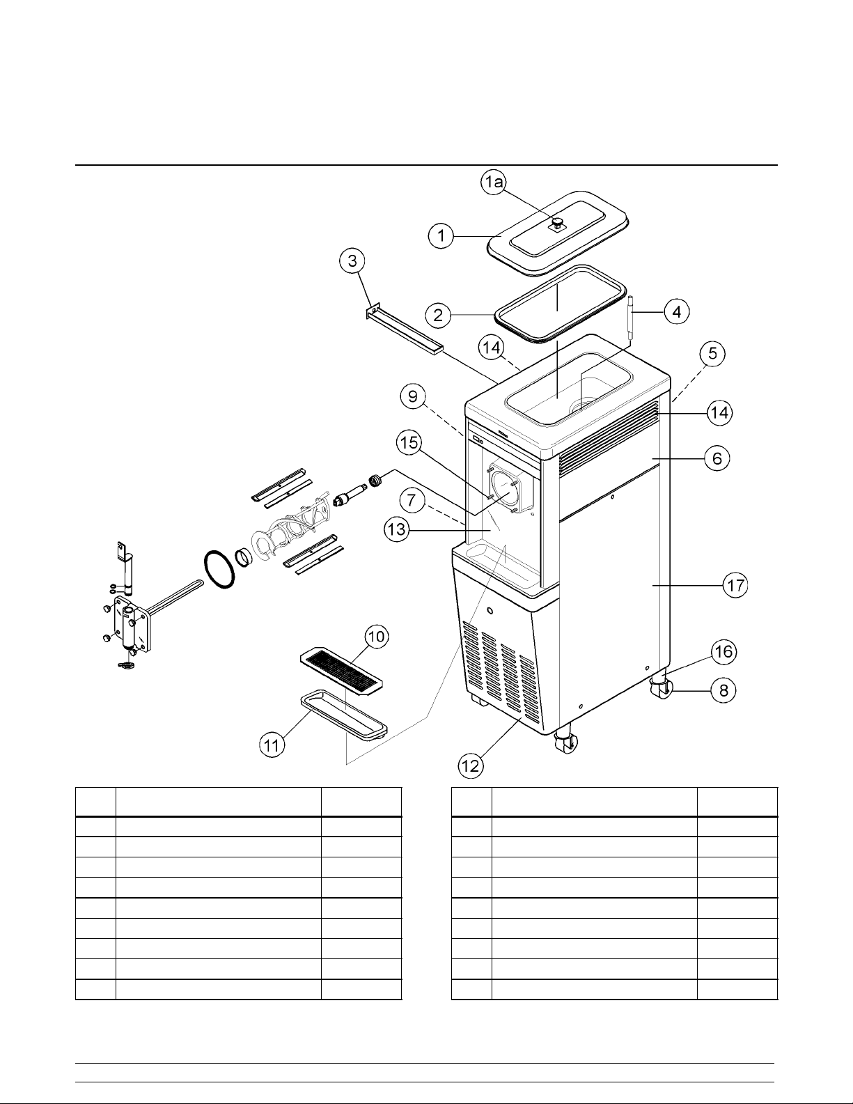
Section 4 Operator Parts Identification
Model 441
Item Description Part No.
1 Cover A.--Hopper-- Standard X38458
1a Knob--Hopper Cover 025429
2 Gasket-- Hopper Cover--20 Qt. 038375
3 Pan--Drip -- 11--5/8 Long 027503
4 Tube-- Feed-- SS 028967--7
5 Panel-- Rear 013637
6 Panel-- Side-- Upper Right 028707--SP
7 Panel A.--Side Lower Left X44853
8 Caster--Swivel-- 5/8 Stem 4” Wheel 018794
Models 441 & 444 Operator Parts Identification
Item Description Part No.
9 Panel-- Side Upper Left 028700
10 Shield--Splash 15” x 5--13/32 022763
11 Tray--Drip 14--7/8 x 5-- 1/8 013690
12 Panel-- Service 049613
13 Panel A.--Front X49600
14 Louver--Side R & L 017471
15 Stud-- Nose 022822
16 Adaptor A.-- Caster X18915
17 Panel A.--Side Lower Right X44855
7
Page 12
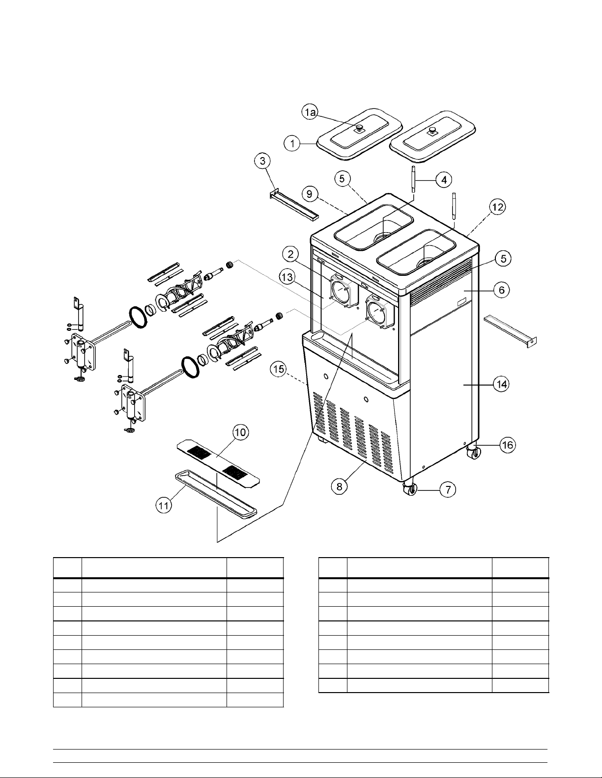
Model 444
Item Description Part No.
1 Cover A.--Hopper--Insulated X39291
1a Knob--Hopper Cover 025429
2 Stud-- Nose Cone 022822
3 Pan--Drip 11-- 5/8 Long 027503
4 Tube-- Feed-- SS 028967--7
5 Louver-- Side Left & Right 017471
6 Panel-- Upper Side Right 028701
7 Caster--Swivel-- 5/8 Stem 4” Wheel 018794
8 Panel-- Service 024439
Operator Parts Identification
Item Description Part No.
9 Panel-- Upper Side Left 028700
10 Shield-- Splash 037041
11 Tray-- Drip 014533
12 Panel-- Rear 017563
13 Panel A.--Front X14239
14 Panel A.--Side Right X44855
15 Panel A.--Side Left X44853
16 Adaptor A.-- Caster X18915
8
Models 441 & 444
Page 13
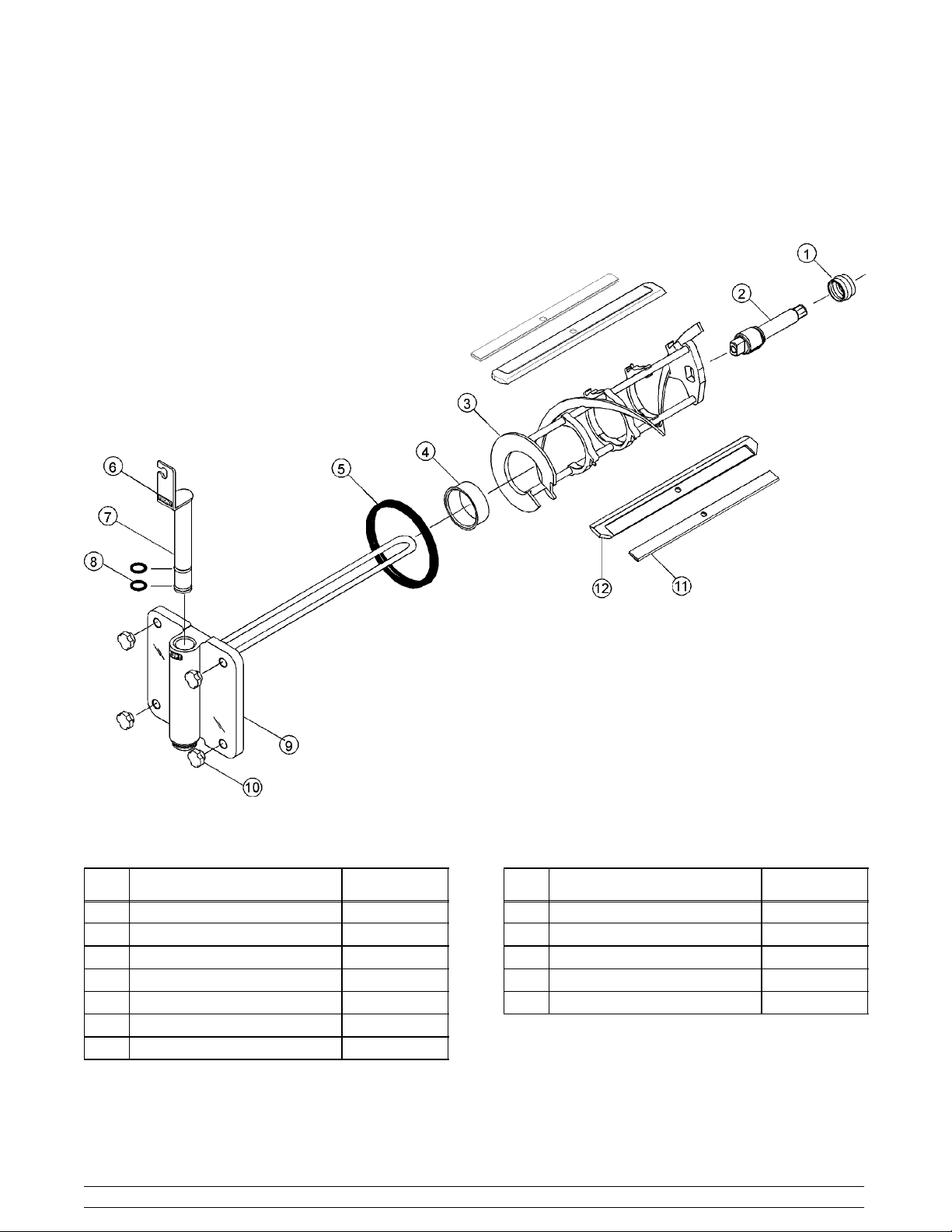
Models 441 & 444 Door Assembly
Item Description Part No.
1 Seal--Drive Shaft 032560
2 Shaft-- Beater 033498
3 Beater A.--7 Qt.--1 Pin Support X46233
4 Bearing-- Front 013116
5 Gasket-- Door 5.177 ID x 5.9380 016672
6 Decal--Lift Plate Front 015200
7 Valv e A . - -Dra w X13624--SP
Models 441 & 444 Operator Parts Identification
Item Description Part No.
8 O-- Ring 1--1/16 OD x .139 W 020571
9 Door A. --1 Spout 7 Qt. X30272--SER
10 Nut-- Stud 021508
11 Clip--Scraper Blade -- 8.75 Inch 046238
12 Blade-- Scraper--Plastic 046237
9
Page 14
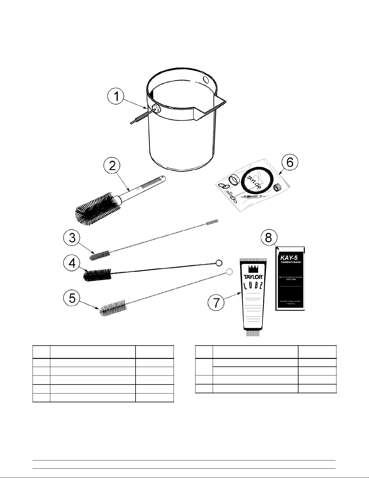
Accessories
Item Description Part No.
1 Pail-- Mix -- 1 0 Qt. 013163
2 Brush-- Mix Pump Body 3 x 7 023316
3 Brush-- Double Ended 013072
4 Brush-- Rear Bearing 013071
5 Brush-- Draw Valve 014753
Operator Parts Identification
Item Description Part No.
Kit A.--Tune Up (Model 441) X33351
6
Kit A.--Tune Up (Model 444) X36356
7 Lubricant--Taylor 047518
8 Sanitizer--Kay--5 125 Packets 041082
10
Models 441 & 444
Page 15
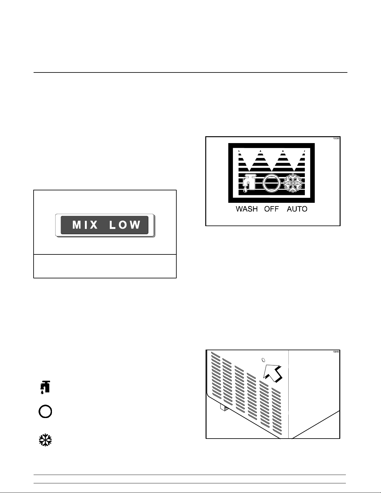
Section 5 Important: To the Operator
Indicator Light “Mix Low”
The Models 441 and 444 are equipped with a “MIX
LOW” light located on the front of the machine. When
the light begins to flash, it indicates that the mix hopper
has a low supply of mix and should be refilled as soon
as possible. Always maintain at least 3” (76 mm) of mix
in the hopper to allow the mix feed assembly to operate
properly. If you neglect to add mix when the light
begins to flash, a freeze--up may occur, causing
eventual damage to the beater, blades, drive shaft,
and freezer door.
Figure 2
Symbol Definitions
Control Switch
The center position is “OFF”. The right position is
“AUTO”, which activates the beater motor and the
refrigeration system. The left position is “WASH”
which activates the beater motor only.
Figure 3
Reset Button
On the Models 441 and 444, the reset button is located
on the lower front panel.
The reset button protects the beater motor from an
overload condition. If an overload occurs, the reset
mechanism will trip. To properly reset the freezer,
place the control switch in the “OFF” position. Press
the reset button firmly. Place the control switch in the
“WASH” position and observe the freezer’s
performance. Once satisfied, place the control switch
back in the “AUTO” position.
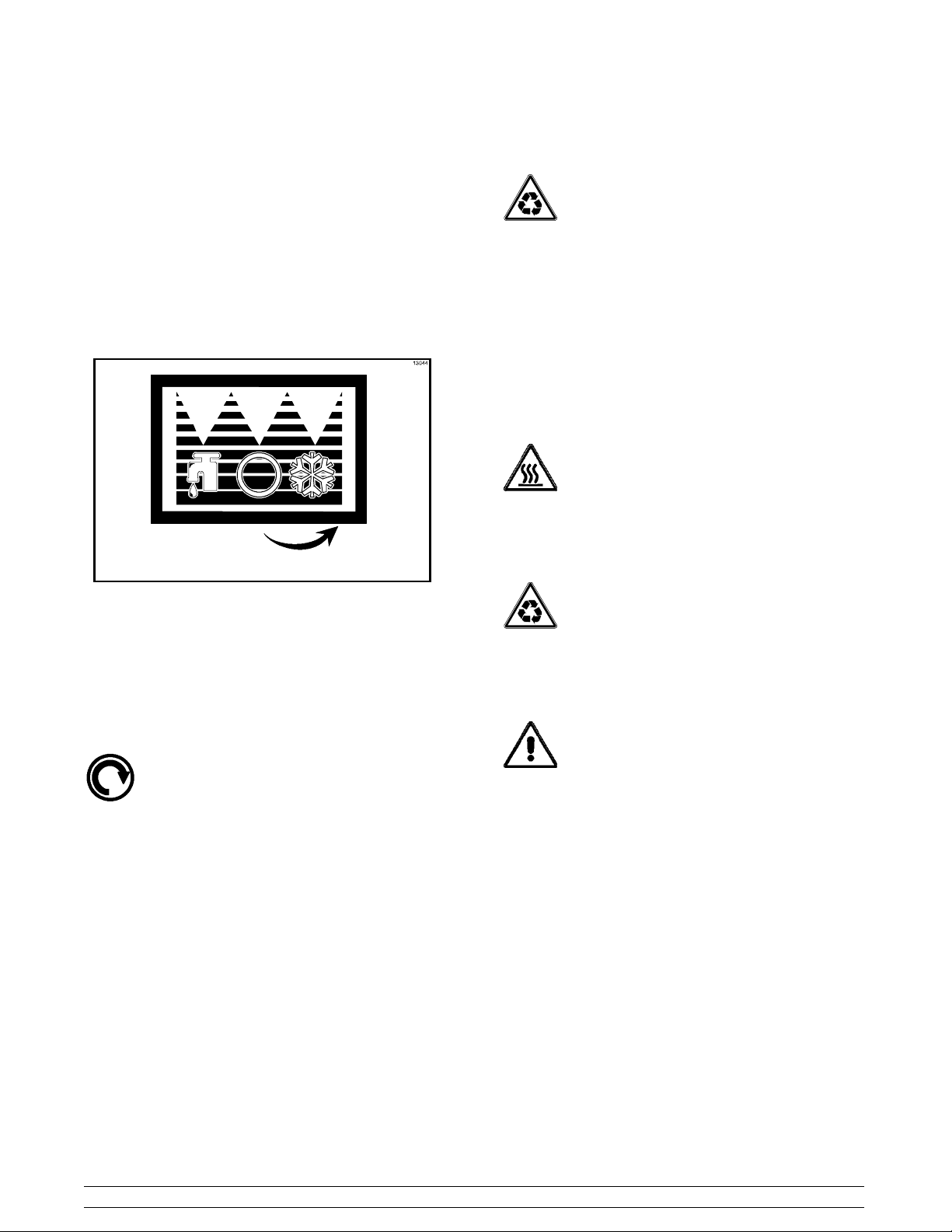
The following chart identifies the symbol definitions
used on the operator switches.
= The “WASH” position.
= The “OFF” position.
= The “ON/AUTO” position.
Models 441 & 444 Important: To the Operator
11
Figure 4
Page 16

Thermistor Control
The viscosity (thickness) of the product is controlled by
a temperature sensing device called the thermistor. To
achieve a thicker product, turn the control clockwise,
and turn the control counterclockwise to achieve a
thinner product. Allow the refrigeration system to cycle
on and off 2 or 3 times before an accurate consistency
can be evaluated.
Separate Hopper Refrigeration
System (SHR)
The Separate Hopper Refrigeration System (SHR) is
a standard feature. The SHR incorporates the use of
a separate small refrigeration system to maintain the
mix temperature in the hopper to below 40_F. ( 4. 4 _C.)
This assures bacteria control.
Important: To the Operator
12
Models 441 & 444
Page 17
Section 6 Operating Procedures
The Model 441 has been selected to show you the
pictured step--by--step operating procedures for both
models contained in this manual. These models, for
practical purposes of operation, are the same.
They both store 20 quarts (18.9 liters) of mix in the
hopper. The mix then flows by gravity through a mix
feed tube down into the freezing cylinder.
Locate your model number below to determine the
characteristics of your freezer:
441: (1) 7 quart (6.6 liter) freezing cylinder.
444: (2) 7 quart (6.6 liter) freezing cylinders.
We begin our instructions at the point where we enter
the store in the morning and find the parts
disassembled and laid out to air dry from the previous
night’s cleaning.
The following procedures will show you how to
assemble the parts into the freezer, sanitize them, and
prime the freezer with fresh mix in preparation to serve
your first portion.
If you are disassembling the machine for the first time
or need information to get to this starting point in our
instructions, turn to page 19, “Disassembly” and start
there.
Assembly
MAKE SURE THE CONTROL SWITCH IS
IN THE “OFF” POSITION TO ELIMINATE THE
CHANCE OF MOVING PARTS.
Figure 5
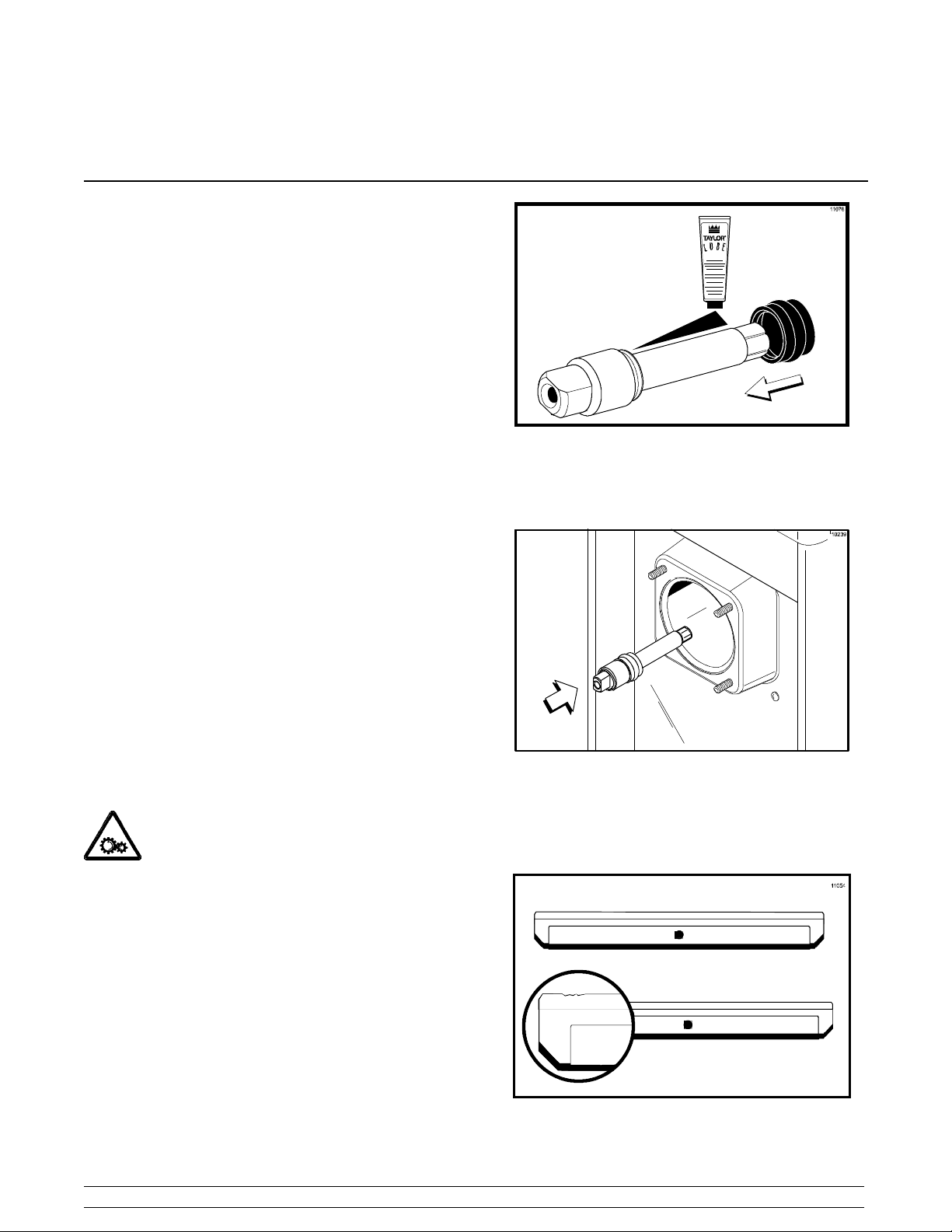
Insert the drive shaft through the rear shell bearing in
the freezing cylinder and engage the hex end firmly
into the gear box coupling.
Figure 6
Step 2
Install the beater assembly. First check the scraper
blade(s) for any nicks or signs of wear. If any nicks are
present, replace the blade(s).
Note: When lubricating parts, use an approved food
grade lubricant (example: Taylor Lube).
Step 1
Install the drive shaft. Lubricate the groove and shaft
portion that comes in contact with the bearing on the
beater drive shaft. Slide the seal over the shaft and
groove until it fits into place. DO NOT lubricate the hex
end of the drive shaft. Fill the inside portion of the seal
with 1/4” more lubricant and evenly lubricate the flat
side of the seal that comes in contact with the bearing.
Models 441 & 444 Operating Procedures
13
Figure 7
050323
Page 18
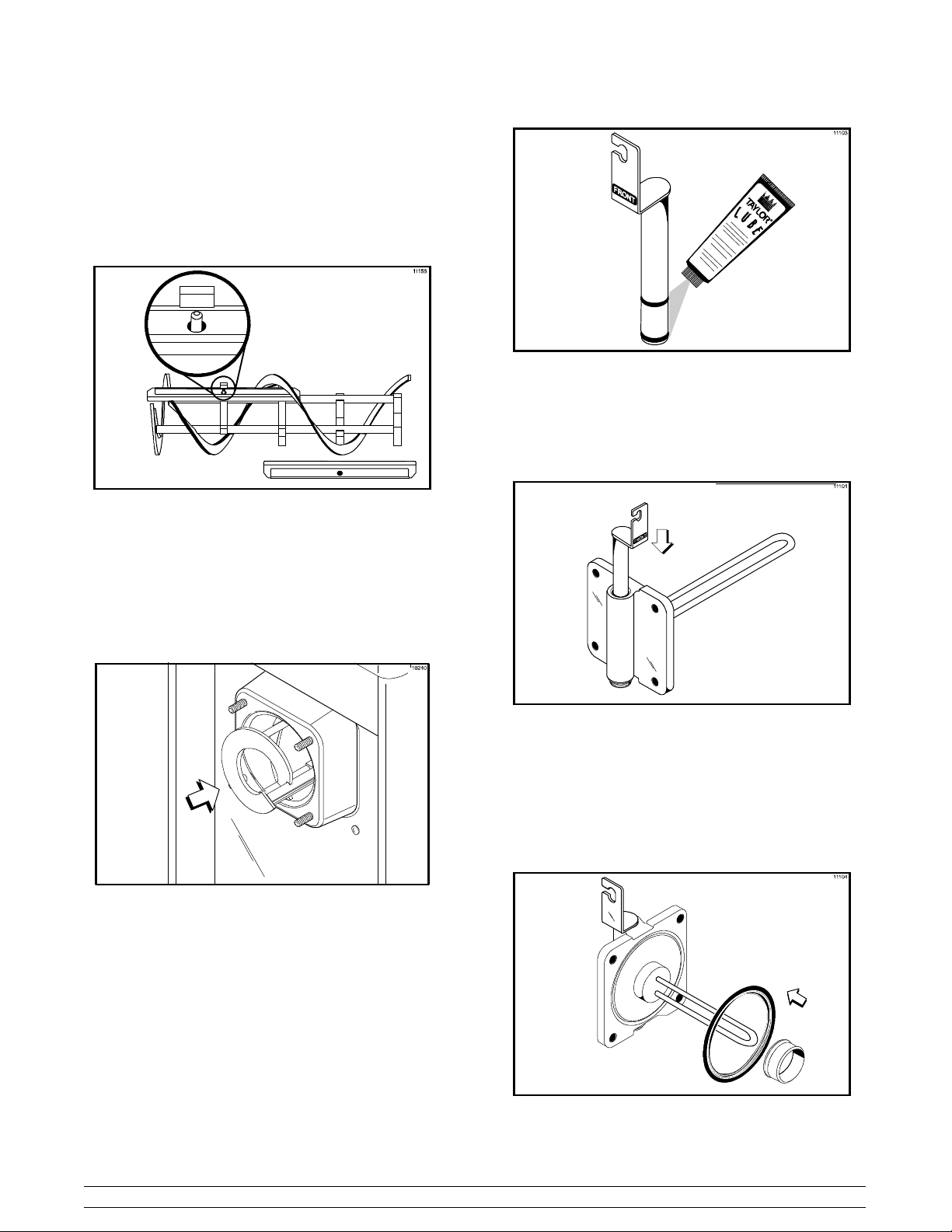
Note: To prevent costly damage, the hole in the
scraper blade must fit securely over the pin.
If the blades are in good condition, place the rear
scraper blade over the rear holding pin on the beater,
knife edge to the outside.
Figure 8
Holding the rear blade on the beater, slide the
assembly halfway into the freezing cylinder. Install the
front scraper blade over the front holding pin. Slide the
beater assembly the rest of the way into the freezing
cylinder.
Figure 10
Lubricate the inside of the freezer door spout, top and
bottom. Insert the draw valve into the freezer door from
the top. It will be necessary to rotate the draw valve to
the right when assembling the door to the freezer.
Figure 9
Make sure the beater assembly is in position over the
drive shaft. Turn the beater slightly to be certain that
the beater is properly seated. When in position, the
beater will not protrude beyond the front of the freezing
cylinder.
Step 3
Install the draw valve. Slide the two o--rings into the
grooves on the draw valve and lubricate them with
Taylor Lube.
Figure 11
Step 4
Install the freezer door. Place the freezer door gasket
into the groove on the back of the freezer door. Slide
the front bearing over the baffle rod so the flanged
edge is against the door. Do not lubricate the gasket
or bearing.
Figure 12
Operating Procedures
14
Models 441 & 444
Page 19
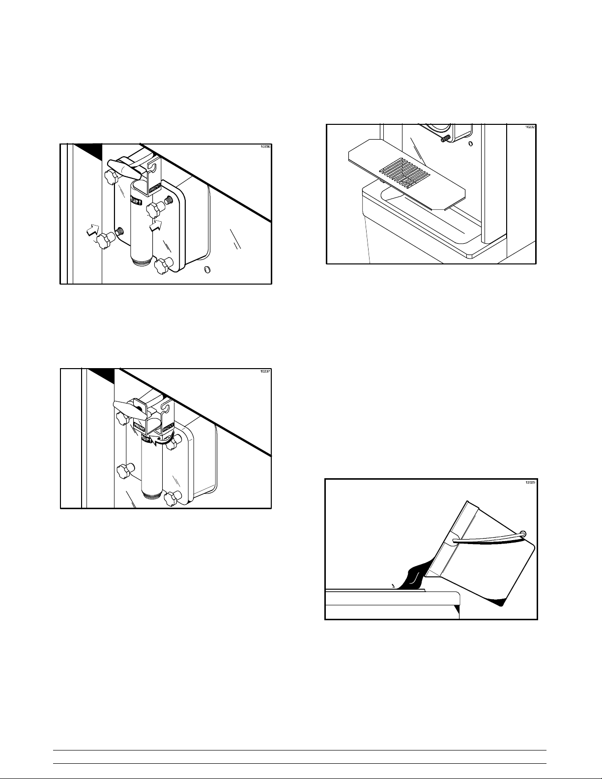
Insert the baffle rod through the beater in the freezing
cylinder. With the door seated on the freezer studs,
install the handscrews. Tighten equally in a crisscross
pattern to insure that the door is snug.
Step 6
Install the front drip tray and splash shield under the
door spout(s).
Figure 15
Figure 13
Rotate the draw valve bracket to the left. Center it into
position by raising the draw arm and placing it into the
slotted groove of the draw valve bracket.
Figure 14
Step 5
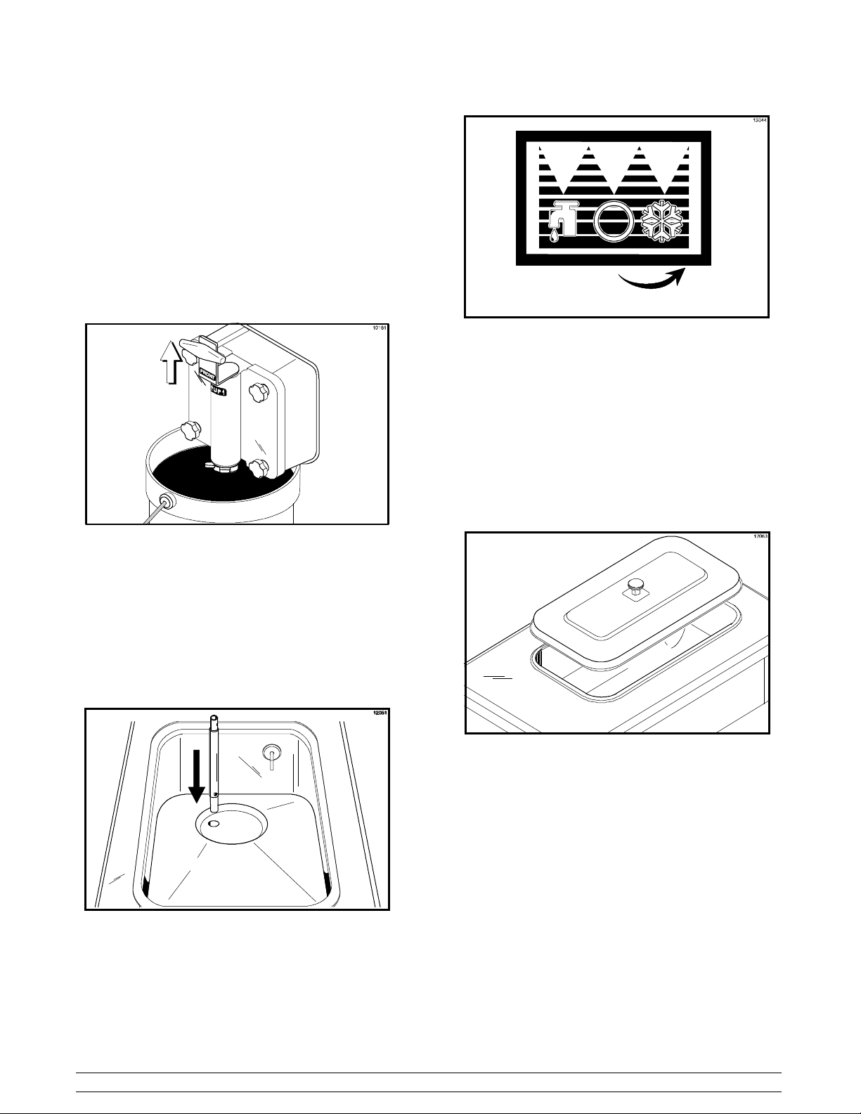
Lay the mix feed tube and the hopper gasket in the
bottom of the mix hopper.
Step 7
Slide the rear drip pan into the hole(s) in the side panel.
Sanitizing
Step 1
Prepare a pail of approved 100 PPM sanitizing solution
(examples: 2--1/2 gal. [9.5 liters] of Kay--5R or 2 gal.
[7.6 liters] of Stera--SheenR). USE WARM WATER
AND FOLLOW THE MANUFACTURER’S
SPECIFICATIONS.
Step 2
Pour the sanitizing solution into the hopper and allow
it to flow into the freezing cylinder.
Note: Hopper gaskets are not used on the Model 444.
Repeat Steps 1 through 5 for the other side of the
freezer on the Model 444.
Models 441 & 444 Operating Procedures
15
Figure 16
080924
Page 20
Step 3
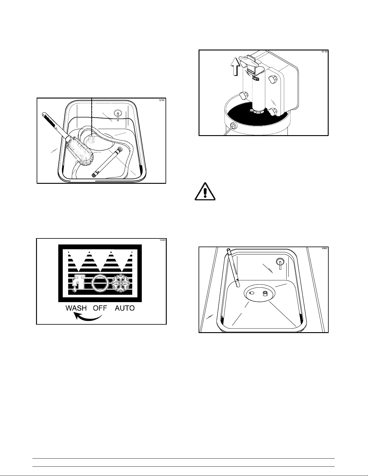
While the solution is flowing into the freezing cylinder,
brush clean the hopper. While cleaning the mix hopper,
take particular care in brushing the mix level sensing
probe on the rear wall of the hopper, the mix inlet hole,
the hopper gasket, and the mix feed tube.
Figure 17
Figure 19
Step 6
When the sanitizer stops flowing from the door spout,
lower the draw arm and place the control switch in the
“OFF” position.
Step 4
Place the control switch in the “WASH” position. This
will cause the sanitizing solution in the freezing
cylinder to agitate. Allow the solution to agitate for five
minutes.
Figure 18
Step 5
Place an empty pail beneath the door spout and raise
the draw arm. Draw off all the sanitizing solution.
Note: You have just sanitized the freezer;
therefore, be sure your hands are sanitized before
continuing these instructions.
Step 7
Stand the mix feed tube in the corner of the mix hopper,
and assemble the hopper gasket.
Figure 20
Repeat Steps 1 through 7 for the other side of the
freezer on the Model 444.
Operating Procedures
16
Models 441 & 444
Page 21
Priming
Prime the machine as close to the time of first product
draw as possible.
Step 1
Place a mix pail beneath the door spout and raise the
draw arm. Pour two gallons (7.6 liters) of fresh mix into
the hopper and allow it to flow down into the freezing
cylinder. This will force out any remaining sanitizing
solution.
Figure 23
Step 5
Fill the hopper with mix. As the mix level comes in
contact with the mix level sensing probe on the rear
wall of the hopper, the “MIX LOW” light will extinguish.
Note: Always maintain at least 3” (76 mm) of mix in
the hopper to allow the mix feed assembly to operate
properly.
Step 6
Place the mix hopper cover in position.
Figure 21
Step 2
When full strength mix is flowing from the door spout,
lower the draw arm.
Step 3
When the mix has stopped bubbling down into the
freezing cylinder, install the mix feed tube into the mix
inlet hole.
Figure 22
Step 4
Place the control switch in the “AUTO” position. When
the unit cycles off, the product will be at serving
temperature.
Figure 24
Repeat Steps 1 through 5 for the other side of the
freezer on the Model 444.
Closing Procedure
To disassemble your unit, the following items will be
needed:
S Two cleaning pails
S Sanitized stainless steel rerun can with lid
S Necessary brushes (provided with freezer)
S Cleaner
S Single service towels
Models 441 & 444 Operating Procedures
17
Page 22
Draining Product From the
Freezing Cylinder
Step 1
Place the control switch in the “OFF” position.
Step 2
Remove the hopper cover, the hopper gasket, and the
mix feed tube. Take these parts to the sink for cleaning.
Step 3
If local health codes permit the use of rerun,place
a sanitized, NSF approved stainless steel rerun
container beneath the door spout. Place the control
switch in the “WASH” position and raise the draw arm.
When all the product stops flowing from the door
spout, lower the draw arm and place the control switch
in the “OFF” position. Place the sanitized lid on the
rerun container and place it in the walk--in cooler.
Note: If local health codes DO NOT permit the use
of rerun, the product must be discarded. Follow the
instructions in the previous step, except drain the
product into a mix pail and properly discard the mix.
Repeat these steps for the second freezing cylinder
on the Model 444.
ALWAYS FOLLOW LOCAL HEALTH CODES.
Cleaning
Step 1
Prepare a pail of approved 100 PPM cleaning solution
(examples: 2--1/2 gal. [9.5 liters] of Kay--5R or 2 gal.
[7.6 liters] of Stera--SheenR). USE WARM WATER
AND FOLLOW THE MANUFACTURER’S
SPECIFICATIONS.
Step 2
Pour the cleaning solution into the hopper and allow it
to flow into the freezing cylinder.
Step 3
While the solution is flowing into the freezing cylinder,
brush clean the mix hopper, the mix inlet hole, and the
mix level sensing probe.
Step 4
Place the control switch in the “WASH” position. This
will cause the cleaning solution in the freezing cylinder
to agitate.
Step 5
Place an empty mix pail beneath the door spout and
raise the draw arm. Draw off all the cleaning solution.
When the solution stops flowing from the door spout,
lower the draw arm and place the control switch in the
“OFF” position.
Rinsing
Step 1
Pour two gallons (7.6 liters) of cool, clean water into
the mix hopper. With the brushes provided, scrub the
mix hopper, the mix inlet hole, and the mix level
sensing probe.
Step 2
With a mix pail beneath the door spout, place the
control switch in the “WASH” position and raise the
draw arm. Drain all the rinse water from the freezing
cylinder. When the rinse water stops flowing from the
door spout, lower the draw arm and place the control
switch in the “OFF” position.
Repeat this procedure until the rinse water being
drawn from the freezing cylinder is clear .
Repeat these steps for the second freezing cylinder
on the Model 444.
Repeat Steps 1 through 5 for the second freezing
cylinder on the Model 444.
080924
Operating Procedures
18
Models 441 & 444
Page 23
Disassembly
Step 3
From the freezer door(s) remove:
Note: Failure to remove parts, brush clean and then
air dry these parts, will result in damage to the related
parts.
Step 1
BE SURE THE CONTROL SWITCH IS IN
THE “OFF” POSITION TO ELIMINATE THE
CHANCE OF MOVING PARTS.
Step 2
Remove the handscrews, the freezer door, the gasket,
the front bearing, the beater, the scraper blade(s), and
the drive shaft from the freezing cylinder. Take these
parts to the sink for cleaning.
Step 3
Remove the rear drip pan from the side panel.
Note: If the drip pan is filled with an excessive amount
of mix, it is an indication that the drive shaft seal should
be replaced or was improperly lubricated.
Repeat these steps for the second freezing cylinder
on the Model 444.
Step 4
Remove the front drip tray and the splash shield.
S the gasket(s)
S the front bearing(s)
S the draw valve(s)
Remove all o--rings.
Note: To remove o--rings, use a single service towel
to grasp the o--ring. Apply pressure in an upward
direction until the o--ring pops out of its groove. With
the other hand, push the top of the o--ring forward. It
will roll out of the groove and can be easily removed.
If there is more than one o--ring to be removed, always
remove the rear o--ring first. This will allow the o--ring
to slide over the forward rings without falling into the
open grooves.
Step 4
Thoroughly brush clean all disassembled parts in the
cleaning solution, making sure all lubricant and mix film
is removed. Take particular care to brush clean the
draw valve core in the freezer door(s). Place all the
cleaned parts on a clean dry surface to air dry
overnight.
Step 5
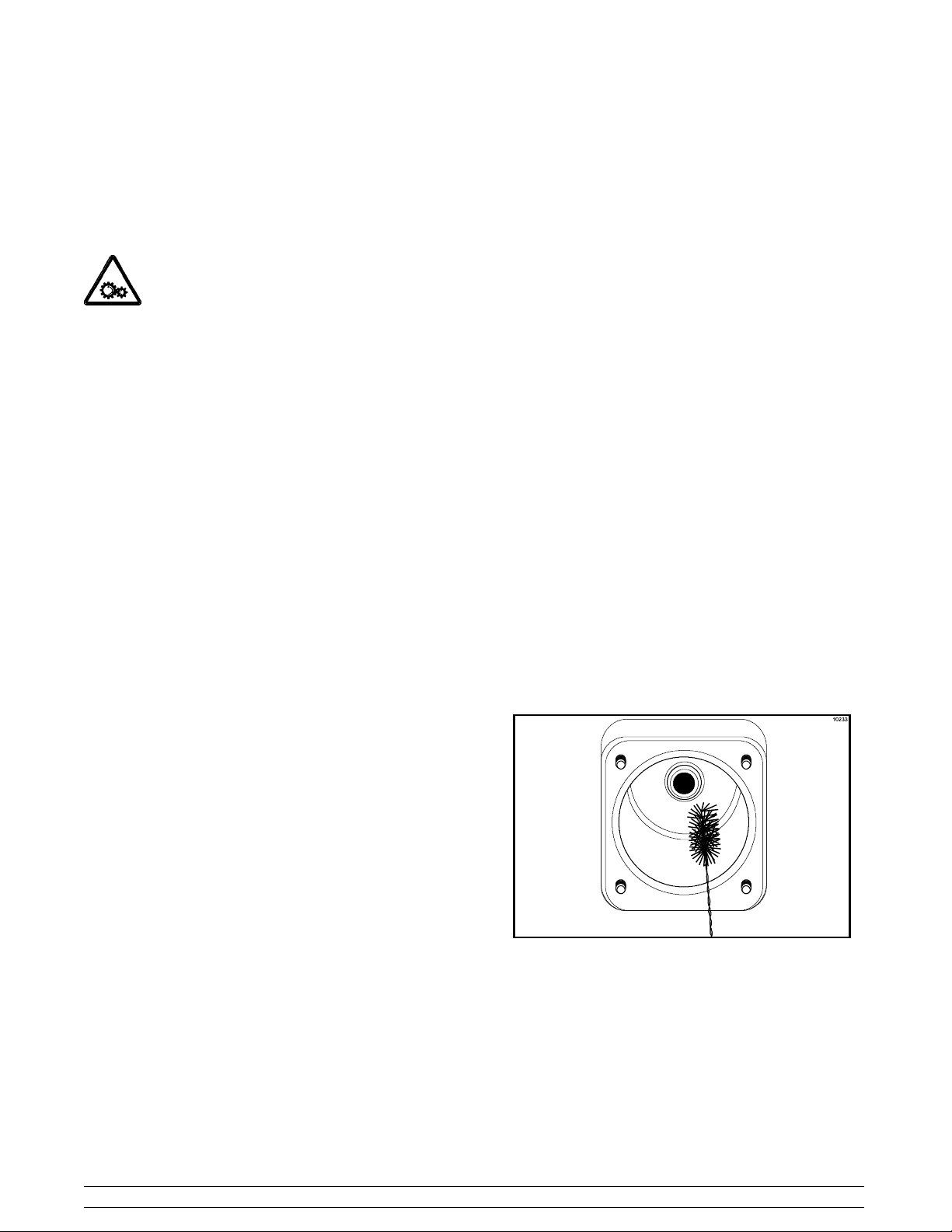
Return to the freezer with a small amount of cleaning
solution. With the black bristle brush, brush clean the
rear shell bearing(s) at the back of the freezing
cylinder(s).
Brush Cleaning
Step 1
Prepare a sink with an approved cleaning solution
(examples: Kay--5R or Stera--SheenR). USE WARM
WATER AND FOLLOW THE MANUFACTURER’S
SPECIFICATIONS.
If an approved cleaner other than Kay--5R or
Stera--SheenR is used, dilute it according to the label
instructions. IMPORTANT: Follow the label directions.
Too STRONG of a solution can cause parts damage.
Too MILD of a solution will not provide adequate
cleaning. Make sure all brushes provided with the
freezer are available for brush cleaning.
Step 2
Remove the seal(s) from the drive shaft(s).
Figure 25
Step 6
Wipe clean all exterior surfaces of the freezer.
080401
Models 441 & 444 Operating Procedures
19
Page 24
Section 7 Important: Operator Checklist
During Cleaning and Sanitizing
ALWAYS FOLLOW LOCAL HEALTH CODES.
Cleaning and sanitizing schedules are governed
by federal, state, or local regulatory agencies,
and must be followed accordingly. If the unit
has a “Standby mode”, it must not be used in
lieu of proper cleaning and sanitizing
procedures and frequencies set forth by the
ruling health authority. The following check
points should be stressed during the cleaning
and sanitizing operations.
CLEANING AND SANITIZING MUST BE
PERFORMED DAILY.
T roubleshooting Bacterial Count
j 1. Thoroughly clean and sanitize the machine
regularly, including complete disassembly and
brush cleaning.
j 2. Use all brushes supplied for thorough cleaning.
The brushes are specially designed to reach all
mix passageways.
j 3. Use the white bristle brush to clean the mix inlet
hole which extends from the mix hopper down
to the rear of the freezing cylinder.
j 4. Use the black bristle brush to thoroughly clean
the rear shell bearing located at the rear of the
freezing cylinder. Be sure there is a generous
amount of cleaning solution on the brush.
j 5. IF LOCAL HEALTH CODES PERMIT THE
USE OF RERUN, make sure the mix rerun is
stored in a sanitized, covered stainless steel
container and is used the following day. DO
NOT prime the machine with rerun. When using
rerun, skim off the foam and discard, then mix
the rerun with fresh mix in a ratio of 50/50 during
the day’s operation.
j 6. On a designated day of the week, run the mix as
low as feasible and discard after closing. This
will break the rerun cycle and reduce the
possibility of high bacteria and coliform counts.
j 7. Properly prepare the cleaning and sanitizing
solutions. Read and follow label directions
carefully. Too strong of a solution may damage
the parts and too weak of a solution will not do
an adequate job of cleaning or sanitizing.
j 8. The temperature of the mix in the mix hopper
and walk--in cooler should be below 40_F.
(4.4_C.).
Regular Maintenance Checks
j 1. Rotate scraper blades to allow both sides of the
knife edge to wear evenly. This will contribute to
self--sharpening and help maintain fast, efficient
freezing.
j 2. Replace scraper blades that are nicked,
damaged or worn.
j 3. Before installing the beater, be certain that
scraper blades are properly attached over the
pins.
j 4. Check the rear shell bearing for signs of wear
(excessive mix leakage in rear drip pan) and be
certain it is properly cleaned.
j 5. Using a screwdriver and cloth towel, keep the
rear shell bearing and the female hex drive
socket clean and free of lubricant and mix
deposits.
j 6. Dispose of o--rings and seals if they are worn,
torn, or fit too loosely, and replace with new
ones.
080401
Important: Operator Checklist
20
Models 441 & 444
Page 25

j 7. Follow all lubricating procedures as outlined in
“Assembly”.
j 8. Check the condensers for accumulation of dirt
and lint. Dirty condensers will reduce the
efficiency and capacity of the machine.
Condensers should be cleaned monthly with a
soft brush. Never use screwdrivers or other
metal probes to clean between the fins.
Note: For machines equipped with an air filter,
it will be necessary to vacuum clean the filters
on a monthly schedule.
j 9. On water cooled units, check the water lines for
kinks or leaks. Kinks can occur when the
machine is moved back and forth for cleaning or
maintenance purposes. Deteriorated or
cracked water lines should be replaced only by
an authorized Taylor technician.
Winter Storage
If the place of business is to be closed during the winter
months, it is important to protect the freezer by
following certain precautions, particularly if the
building is subject to freezing conditions.
Disconnect the freezer from the main power source to
prevent possible electrical damage.
On water cooled freezers, disconnect the water
supply. Relieve pressure on the spring in the water
valve. Use air pressure on the outlet side to blow out
any water remaining in the condenser. This is
extremely important. Failure to follow this procedure
may cause severe and costly damage to the
refrigeration system.
Your local Taylor Distributor can perform this service
for you.
Wrap detachable parts of the freezer such as the
beater, blades, drive shaft, and freezer door. Place
these parts in a protected, dry place. Rubber trim parts
and gaskets can be protected by wrapping them with
moisture--proof paper. All parts should be thoroughly
cleaned of dried mix or lubrication which attract mice
and other vermin.
080401
Models 441 & 444 Important: Operator Checklist
21
Page 26

Section 8 Troubleshooting Guide
PROBLEM PROBABLE CAUSE REMEDY PAGE
REF.
1. No product being
dispensed with the draw
valve open and the control
switch in AUTO.
a. The freezer door is
installed upside down.
b. There is a freeze--up in
the mix inlet hole.
c. The beater motor is out on
reset.
d. The beater is rotating
counterclockwise.
e. The draw valve is
connected to the draw
arm incorrectly.
f. The circuit breaker is off
or the fuse is blown.
g. There is inadequate mix in
the hopper.
h. The feed tube is installed
upside down.
a. Install the door correctly. 14
b. Call service technician to
adjust the hopper
temperature.
c. Reset the freezer. 11
d. Contact service technician
to correct the rotation to
clockwise.
e. The draw valve bracket
must be correctly attached
to the draw arm.
f. Turn the breaker on or
replace the fuse.
g. Fill the hopper with mix. 17
h. Install the feed tube with
the hole in the side in the
down position.
-- --
-- --
15
-- --
17
2. The product is too cold. a. The thermistor control is
set too cold.
b. The draw handle is not
fully closed.
3. The product appears too
thin.
Troubleshooting Guide
a. The thermistor control is
set too warm.
b. There is not enough air
space around the unit.
(A/C)
c. The scraper blade(s) are
worn.
d. Dirty condenser . d. Clean regularly. 21
e. The mix is out of date. e. Use only fresh mix. -- --
f. The beater is rotating
counterclockwise.
22
a. Adjust the thermistor
control knob warmer.
b. The draw handle must be
fully closed.
a. Adjust the thermistor
control knob colder.
b. Allow for adequate air flow
across the condenser.
c. Replace scraper blades
regularly.
f. Contact service technician
to correct rotation to
clockwise.
Models 441 & 444
12
-- --
12
1
25
-- --
Page 27

PROBLEM PROBABLE CAUSE REMEDY PAGE
REF.
3. The product appears too
thin. (Cont’d.)
4. The mix in the hopper is
too cold.
5. The mix in the hopper is
too warm.
6. The drive shaft is stuck in
the gear box coupling.
g. Product is overbeaten. g. Draw off some product to
allow fresh product to
enter the freezing cylinder.
h. Loss of water (W/C) h. Locate cause of water
loss and correct.
a. The temperature is out of
adjustment.
a. The temperature is out of
adjustment.
b. Hopper cover is not in
position.
c. The control switch is OFF. c. Place the control switch in
d. Warm mix was placed in
the hopper.
a. Rounded corners of drive
shaft, coupling, or both.
a. Call service technician to
adjust the hopper
temperature.
a. Call service technician to
adjust the hopper
temperature.
b. Place the cover in
position.
AUTO.
d. Mix added to the hopper
must be below 40_F
(4.4_C).
a. Call service technician to
correct the cause and
replace the necessary
components. Do not
lubricate the end of the
drive shaft.
-- --
21
-- --
-- --
17
17
-- --
-- --
7. The freezing cylinder walls
are scored.
8. Excessive mix leakage
into the rear drip pan.
a. The scraper blade(s) are
not installed over the
beater pins. The pins on
the beater are broken.
b. The beater assembly is
bent.
c. Missing or worn front
bearing.
a. Worn or missing drive
shaft seal.
b. Inadequate lubrication of
drive shaft seal.
c. Worn rear shell bearing. c. Call service technician to
a. Blade(s) must fit over the
pins on the beater. Call
service technician to
repair the beater
assembly.
b. Call service technician to
repair or replace beater
and to correct cause of
insufficient mix in freezing
cylinder.
c. Install or replace the front
bearing.
a. Replace regularly. 25
b. Lubricate properly. 13
replace rear shell bearing.
14
-- --
14
-- --
Models 441 & 444 Troubleshooting Guide
23
Page 28

PROBLEM PROBABLE CAUSE REMEDY PAGE
REF.
8. Excessive mix leakage
into the rear drip pan.
(Cont’d.)
9. Excessive mix leakage
from the door spout.
10. No freezer operation with
the control switch in
AUTO.
d. The drive shaft works
forward.
e. The seal is installed
inside--out on the drive
shaft.
f. The wrong type of
lubricant is being used
(example: petroleum base
lubricant.).
a. Worn or missing draw
valve o--rings.
b. Inadequate lubrication of
the draw valve o--rings.
c. The wrong type of
lubricant is being used
(example: petroleum base
lubricant.).
a. The unit is unplugged. a. Plug into wall receptacle. -- --
b. Circuit breaker off or
blown fuse.
d. Call service technician to
correct.
e. Install correctly. 13
f. Use the proper lubricant
(example: Taylor Lube).
a. Replace regularly. 25
b. Lubricate properly. 14
c. Use the proper lubricant
(example: Taylor Lube).
b. Turn circuit breaker on or
replace fuse.
-- --
-- --
-- --
-- --
c. Beater motor out on reset. c. Reset the freezer. 11
1 1. Low overrun. a. Worn scraper blade(s). a. Replace regularly. 25
12. The freezer door works
loose.
b. The mix feed assembly is
not installed.
c. Product is broken down
from over--beating.
a. The freezer studs are
damaged.
b. The handscrews are
damaged.
c. There are enlarged holes
in the freezer door.
d. The handscrews are not
tightened.
e. The beater assembly is
rubbing the back of the
door.
b. Install in mix inlet hole. 17
c. Draw off some product to
allow fresh product to
enter the freezing cylinder.
a. Call service technician to
replace studs.
b. Replace the handscrews. -- --
c. Replace the door. -- --
d. Tighten the handscrews
equally in a crisscross
pattern.
e. Call service technician to
correct the problem.
-- --
-- --
15
-- --
Troubleshooting Guide
24
Models 441 & 444
Page 29
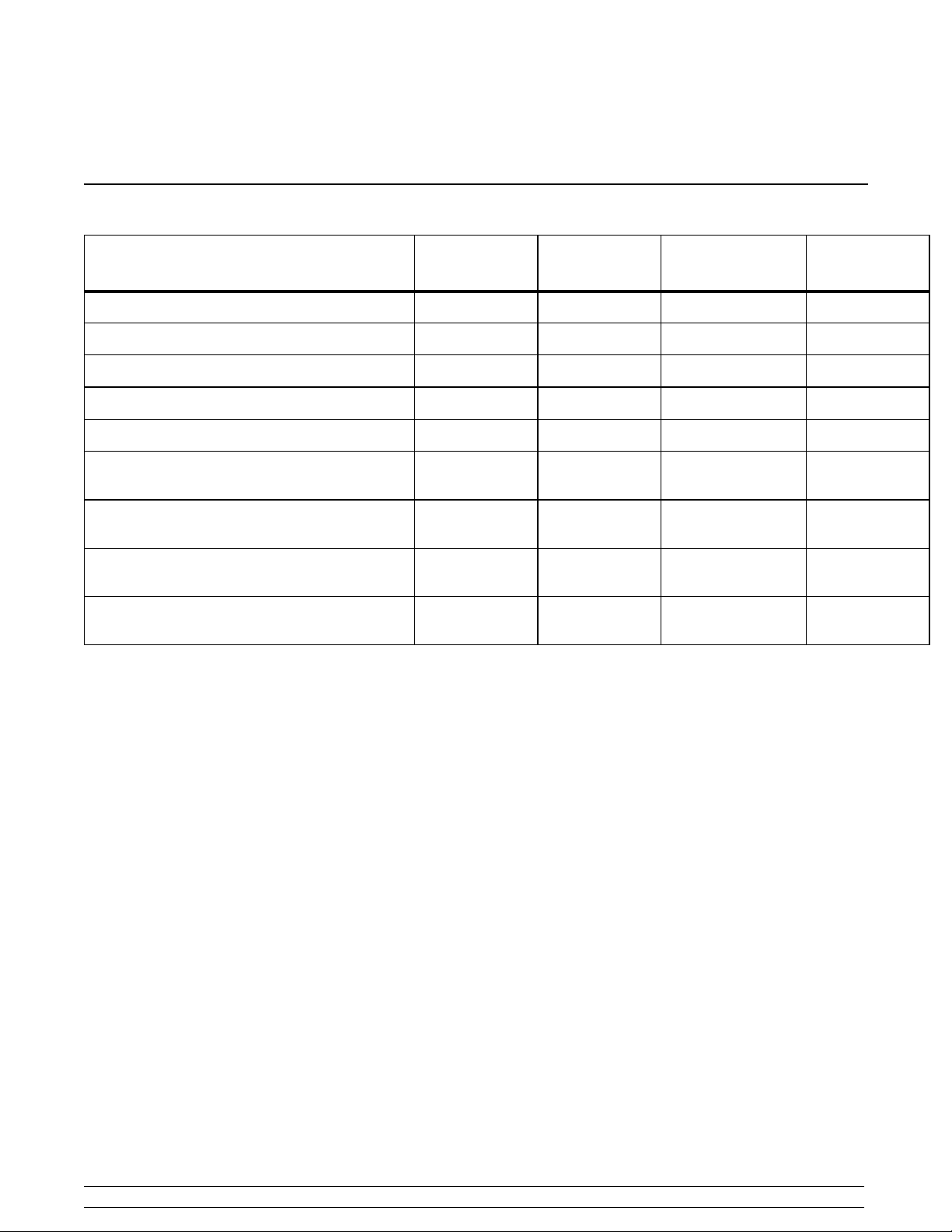
Section 9 Parts Replacement Schedule
PART DESCRIPTION EVERY 3
MONTHS
Scraper Blades X
Drive Shaft Seal X
Freezer Door Gasket X
Front Bearing X
Draw Valve O--Rings X
White Bristle Brush, 3” x 7” Inspect & Replace
White Bristle Brush, 1” x 2” Inspect & Replace
Black Bristle Brush, 1” x 2” Inspect & Replace
Double--Ended Brush Inspect & Replace
Refer to the Part List on page 26 when ordering the above parts.
EVERY 4
MONTHS
EVERY 6
MONTHS
if Necessary
if Necessary
if Necessary
if Necessary
ANNUALLY
Minimum
Minimum
Minimum
Minimum
Models 441 & 444 Parts Replacement Schedule
25
Page 30

Section 10 Parts List
UPDATE
REMARKS PARTS
X46015-- SER CONTROL. FIELD REPLACE
X46015-- SER WITH 063020--03.
WARR.
CLASS
444
QTY.
441
QTY.
NUMBER
DESCRIPTION PART
+BLADE--SCRAPER--PLASTIC 9--13/16L 046237 2 4 000
+CLIP--SCRAPER BLADE*8.75 INCH* 046238 2 4 103
ADAPTOR A.-- CASTER X18915 4 4 103
BEARING-- FRONT 013116 1 2 000
BEATER A.--7QT--1 PIN--SUPPORT X46233 1 2 103
BELT--V --4L430 009613 1 2 000
BLOCK-- TERMINAL 2P--L1,L2 039422 1 2 103 SINGLE PHASE
+ Available Separately
060123
Parts List Models 441 & 444
BOOT--CAPACITOR INSULATING 031314 1 1 000
CAPACITOR-- RUN-- 10 UF/370V 033047 1 1 103
HOUSING A.--W/WHEEL X30160 1 1 103
MOTOR-- BLOWER --208/230V 50/60 046536--27 1 1 103
BLOCK-- TERMINAL 3P-- L1,L2, L3 039423 1 2 103 THREE PHASE
BLOWER A. X47833-- 27 1 1 103
BRUSH--DOUBLE ENDED-- PUMP&FEED T 013072 1 1 000
BRUSH--DRAW VALVE 1 -- 1/2”OD X 3” 014753 1 1 000
BRUSH--MIX PUMP BODY--3”X7”WHITE 023316 1 1 000
BRUSH-- REAR BRG 1IN.DX2IN.LGX14 013071 1 1 000
CASTER--SWV 5/8 STEM 4IN WHEEL 018794 4 4 103
+CAPACITOR-- RUN-- 25 UF/440V 037431 1 2 103 208-- 230/60/1
+CAPACITOR-- START--161-- 193UF/25 031790 1 2 103 208-- 230/60/1
+RELAY--START--COMPRESSOR 037430 1 2 103 208-- 230/60/1
+RELAY--START--COMPRESSOR--TL3G 047702--27 1 1 103 208--230/60/1
+CAPACITOR-- START--60UF--220/275 047703 1 1 103 208-- 230/60/1
+KIT--MOUNTING--COMPRESSOR 047704 1 1 103
+COVER--TERMINAL--COMPRESSOR 047739 1 1 103
COMPRESSOR--M65B163BBCA 048258-- 1 2 512 MAIN
COMPRESSOR TL3G-- R134A 047701--27 1 1 512 SHR 208--230/60/1
CONDENSER-- AC-- 7X6X1.25--2 ROW 027155 1 1 103 SHR
CONDENSER-- AC-- 12LX18HX2.6T-- 3ROW 048233 1 2 103 MAIN
CONTROL-- MIX LEVEL 031799-- 1 2 103
CONTROL--TEMPERATURE 028914 1 1 103
CONTROL--THERMISTOR 063019--03 1 2 103 UNITS PRIOR TO 9/1/05 WERE BUILT WITH
26
+KNOB--ALUMINUM 027422 1 2 103
Page 31

UPDATE
REMARKSWARR.
CLASS
444
QTY.
441
QTY.
PART
NUMBER
DESCRIPTION PARTS
COVER A.-- HOPPER-- STD X38458 1 103
+KNOB-- MIX COVER 025429 1 103
COVER A.-- HOPPER INSULATED X39291 2 103
+KNOB-- MIX COVER 025429 2 103
DECAL--CLEAN INST.--HOPPER 019029 1 1 000
DECAL-- DEC--TAYLOR 021872 1 1 000
DECAL-- TROUBLESHOOTING 038374 1 1 000
DEFLECTOR--BLOWER EXHAUST 046586 1 1 103
+NUT--LOCK KNOB 013649 1 2 000
+O-- RING-- 1-- 1/16 OD X.139W 020571 2 4 000
+KNOB--DRAW VALVE 013635 1 2 103
+VALVE A.--DRAW X13624-- SP 1 2 103
+DECAL--LIFT PLATE FRONT 015200 1 2 000
DIAGRAM--WIRING *441*HP62* 062493-- 1 000 UNITS PRIOR TO 9/1/05 USE 049467--.
DIAGRAM--WIRING *444* 063098-- 1 000 UNITS PRIOR TO 9/1/05 USE 051267--.
DOOR A.-- 1 SPOUT-- 7 QT X30272-- SER 1 2 103
DRYER-- FILTER-- HP62-- 3/8 X 1/4S 048901 1 2 000 MAIN
DRYER-- CAP. TUBE--HP62/R134A 047699 1 1 000 SHR
GASKET--DOOR 5.177ID X 5.938OD 016672 1 2 000
GASKET--HOPPER COVER-- 20 QT --SGL 038375 1 000
GEAR A.*REDUCER 012235 1 2 212
GUARD--BELT 013576 1 103
GUARD--BEL T *342--3--444--5-- 777* 023843 1 103
GUIDEA.--DRIPPAN X28698 1 2 103
HOOD 023263 1 103
HOOD *410--40--41--710--41 023285 1 103
KIT A.--TUNE UP*440--441--444* X33351 1 000
BEARING-- FRONT 013116 1 000
GASKET--DOOR 5.177ID X 5.938O 016672 1 000
O-- RING-- .643 OD X .077W 018572 2 000
O-- RING-- 1-- 1/16 OD X.139W 020571 2 000
O-- RING-- 5/16 OD X .070W 016272 3 000
SEAL--DRIVE SHAFT 032560 1 000
TOOL--CLEANING 0--RING REMOVAL 048260 1 000
KIT A.--TUNE UP*433--444* X36356 1 000
+ Available Separately
060126
Models 441 & 444 Parts List
27
Page 32

UPDATE
REMARKSWARR.
CLASS
444
QTY.
441
QTY.
PART
NUMBER
DESCRIPTION PARTS
BEARING-- FRONT 013116 2 000
GASKET--DOOR 5.177ID X 5.938O 016672 2 000
O-- RING-- .643 OD X .077W 018572 4 000
O-- RING-- 1-- 1/16 OD X.139W 020571 4 000
SEAL--DRIVE SHAFT 032560 2 000
LABEL--DOOR CAUTION 032749 1 1 000
LABEL--MIX COOLING ADJ--INTL SYM 020217 1 1 000
LABEL--WARM-- COLD INT’L SYMBOL 013749 1 2 000
LABEL--WARN-- MOVING PARTS--ENG/SP 024315 3 3 000
LABEL--WARNING-- PANEL-- MOVE PARTS 036529 3 3 000
LIGHT-- ORANGE--ROUND 017450 1 2 103
LIGHT--RED--RECT-- 250V-- MIX LOW 023056-- 27 1 2 103
LOUVER--SIDE 017471 2 2 103
LUBRICANT--TAYLOR 4 OZ. 047518 1 1 000
MAN--OPER 400 SERIES 029405--M 1 1 000
MOTOR-- FAN 105CFM 3000RPM 027309-- 1 1 103 SHR
MOTOR--1.0 HP 013102-- 1 2 212
NUT--STUD *GENERAL USAGE* 021508 4 8 103
PAIL--MIX 10 QT . 013163 1 1 000
PAN--DRIP 11--5/8 LONG 027503 1 2 103
PANEL A. FRONT X49600 1 103
PANEL A. FRONT X14239 1 103
PAN EL A.- -SID E LEFT X44853 1 1 103 LOWER LEFT
PANEL A.-- SIDE RIGHT X44855 1 1 103 LOWER RIGHT
PANEL--REAR 013637 1 103
PANEL--REAR 017563 1 103
PANEL-- SERVICE 024439 1 103
PANEL-- SERVICE 049613 1 103
PANEL-- UPPER SIDE LEFT 028700 1 1 103
PANEL-- UPPER SIDE RIGHT 028701 1 103
PANEL-- UPPER SIDE RIGHT 028701--SP 1 103
PLATE--DEC--SINGLE 022604 1 103
PLATE-- DEC--TWIN 022602 1 103
PLUG--DRIP TRAY HOLE 029595 1 103
PROBE A.-- MIX *SQUARE* X30922 1 2 103
+ Available Separately
Parts List Models 441 & 444
28
Page 33

UPDATE
REMARKSWARR.
CLASS
444
QTY.
441
QTY.
PART
NUMBER
DESCRIPTION PARTS
PROBE A.-- THERMISTOR X31602 1 2 103
PULLEY--AK32 X .625--.6265 007471 1 2 103 BEATER MOTOR
PULLEY--AK74 051013 1 2 103 GEAR
RELAY--3 POLE--20A--208/240 50/ 012725-- 33 1 2 103
RELAY--DPDT-- 20 A--230 V 026581-- 1 103 FAN MOTOR
SANITIZER KAY--5 125 PACKETS 041082 1 1 000
SHAFT--BEATER 033498 1 2 103
+SEAL--DRIVE SHAFT 032560 1 2 000
SHELL A.--INSULATED *19 INCH* X49770 1 2 512
+STUD--NOSE CONE 022822 4 8 103
SHIELD-- MIX--GEAR REDUCER 3--3/8” 013356 1 2 103
SHIELD--SPLASH 037041 1 103
SHIELD-- SPLASH 15”L X 5--13/32”W 022763 1 103
ARM A.-- DRAW VALVE X28874 1 2 103
BRACKET--DOOR SWITCH 028875 1 2 103
E--RING 3/16 .335 O.D. 049178 1 2 000
PIN--PIVOT 015478 1 2 103
SPRING-- RETURN 015342 1 2 103
SWITCH--LEVER--SPDT-- 10A--125-- 25 028889 2 4 103
+CARD--WASH-- OFF--AUTO 014091 1 1 000
STARTER--1 PHASE-- 4.5 TO 7 A 041950--27K 1 2 103 208-- 230/60-- 1
STARTER--3 PHASE-- 3 TO 5 A 041950--33J 1 2 103 208-- 230/60-- 3
SWITCH A.--DRAW *632-- 710-- 31-- 41-- X28891--SER 1 2 103
SWITCH-- ROCKER--DPDT ON-- OFF--ON 014237 1 1 103
SWITCH--PRESSURE 440 PSI-- SOLDER 048230 1 2 103
TRANS.-- 240V PR1/24V SEC 10 VA 030132-- 27 1 2 103
TRAY-- DRIP 14--7/8L X 5-- 1/8 SGL 013690 1 103
TRAY-- DRIP 22--7/8L X 5-- 1/8W 014533 1 103
TRIM-- REAR CORNER 013620 2 103
TRIM-- REAR CORNER L. 013761 1 103 LEFT
TRIM-- REAR CORNER R. 013663 1 103 RIGHT
TUBE--FEED--SHAKE--5/16 HOLE 028967-- 7 1 2 103
VALVE-- ACCESS 1/4 X 3/8 SOLDER 029406 1 103
VALVE-- ACCESS 1/4FL X 1/4SOLDER 044404 1 103
VALVE-- ACCESS 1/4FL X 3/8SDR-- 90 044455 1 2 103
+ Available Separately
Models 441 & 444 Parts List
29
Page 34

UPDATE
REMARKSWARR.
CLASS
444
QTY.
441
QTY.
PART
NUMBER
DESCRIPTION PARTS
VALVE--ACCESS--1/4 MFLX1/4 S-- 90 047016 2 2 103
VALVE-- EPR 1/4S 022665 1 1 103
VALVE--EXP-- AUTO--1/4S X1/4 FPT 046365 1 2 103
+BOOT--EXPANSION VALVE 050900 1 2 000
VARISTOR A.-- SLEEVE TERMINAL X31547 1 2 103
VIDEO--TRAIN FILM--DUALMASTER/SH 043568--V 1 1 000
DISC--SPINNER 013359 1 103
FILTER-- CORCOM 2VR1 032567 1 103
HOOK-- UPPER SPINNER 011173 1 103
50 Hz
BELT--V --4L420 004338 2 103 SINGLE PHASE
BELT--V --4L410 007530 2 103 THREE PHASE
BLOCK--TERMINAL 2P--L1,N 039421 1 2 103 SINGLE PHASE
BLOCK-- TERMINAL 4P-- L1,L2,L3 039424 2 103 THREE PHASE
BLOCK--TERMINAL-- 7 POLE GREEN 024156 1 4 103
CAPACITOR-- RUN-- 30 UF/370V 035734 1 2 103 220--240/50/1
CAPACITOR-- START--161--193UF/25 031790 1 2 103 220--240/50/1
PULLEY--AK34-- 5/8 016055 1 2 103
PULLEY--AK64-- 5/8 007538 1 2 103
RELAY--START--COMPRESSOR 048764 1 2 103 220--240/50/1
WATER COOLED
ADAPTOR--3/8MP X 1/2BARB--BR 011021 2 103
BLOWER--100 CFM 012796--27 1 1 103
BRACKET--MOUNTING--WATER VALVE 038777 1 103
CONDENSER--WC-- COAX 048287 1 2 103
DECAL--SW--MIX REFR. ON/OFF/SYMB 021665 1 000
GUARD--BLOWER 022505 1 1 103
HOSE--RUBBER 1/2”ID X 7/8”OD R50200 4ft 10ft 000
OUTLET A.-- TEE X25900 1 103
PAN EL A.- -SID E LO WE R X24397 2 2 103
SWITCH--PRESSURE 350 PSI-- SOLDER 048231 1 2 103
TEE--3/8’’ PIPE WATER VALVE 032953 1 103
VALVE--WATER 3/8 REG/HEAD PRESS 046686 1 2 103
PANEL SPINNER
SPINNER A.-- PANEL-- SYRUP X34372-- 27 1 103 WITH SYRUP RAIL
+ Available Separately
Parts List Models 441 & 444
30
Page 35

UPDATE
REMARKSWARR.
CLASS
444
QTY.
441
QTY.
PART
NUMBER
DESCRIPTION PARTS
MOTOR--SPINNER MODEL 22-- 230 020101-- 27 1 103
MOUNT A.--PANEL SPINNER *SYRU X34373 1 103
PLATE A.--SWITCH *SPINNER A.* X34363 1 103
PLATE--REAR UPPER 013835 1 103
SCREW--SPINNER DISC 013360 1 000
STUD--1/4--20X21/4STL.ZP 020102 1 103
SWITCH--SNAP--SPDT--20A/125-- 250 013192 1 103
DISC--SPINNER 013359 1 103
FILTER-- CORCOM 2VR1 032567 1 103
HOOK--LOWER CUPREST 011172 1 103
HOOK-- UPPER SPINNER 011173 1 103
MOTOR--SPINNER MODEL 22-- 230 020101-- 27 1 103
MOUNT A.--PANEL SPINNER X34365 1 103
PLATE A.--SWITCH *SPINNER A.* X34363 1 103
PLATE--REAR LOWER 013836 1 103
PLATE--REAR UPPER 013835 1 103
SCREW--SPINNER DISC 013360 1 000
SPACER-- CUP 014015 1 103
STUD--1/4--20X21/4STL.ZP 020102 2 103
SWITCH--SNAP--SPDT--20A/125-- 250 013192 1 103
SPINNER A.-- PANEL X34362-- 27 1 103 W/OUT SYRUP RAIL
SYRUP RAIL
JAR-- SYRUP--PLASTIC--3 QT. 012875 3 103
PANEL A.-- FRONT--SYRUP *441 X49632 1 103
PANEL-- SERVICE 019230 1 103
PUMP-- SYRUP CHOCOLATE 012877 1 103
PUMP--SYRUP--PLAIN 012876 2 103
+ Available Separately
Models 441 & 444 Parts List
31
Page 36
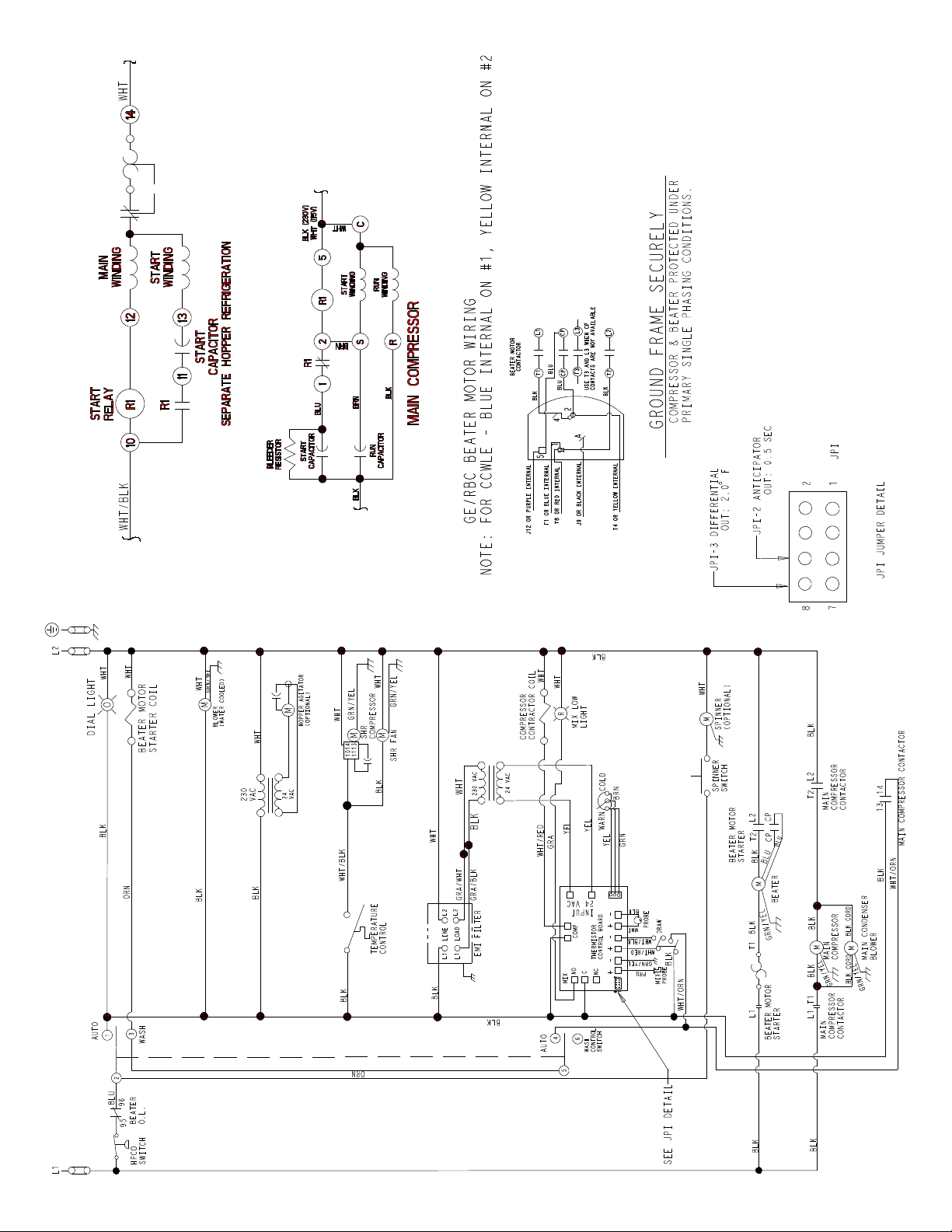
Model 441
062493--27
Rev . 4/08
Page 37
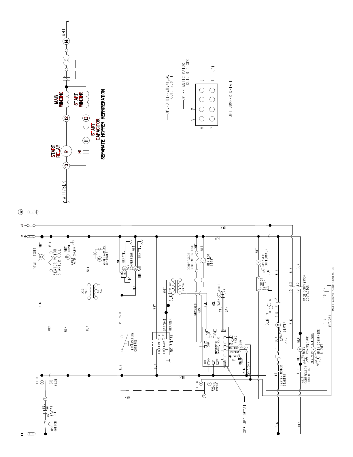
Model 441
062493--33
Rev . 4/08
Page 38
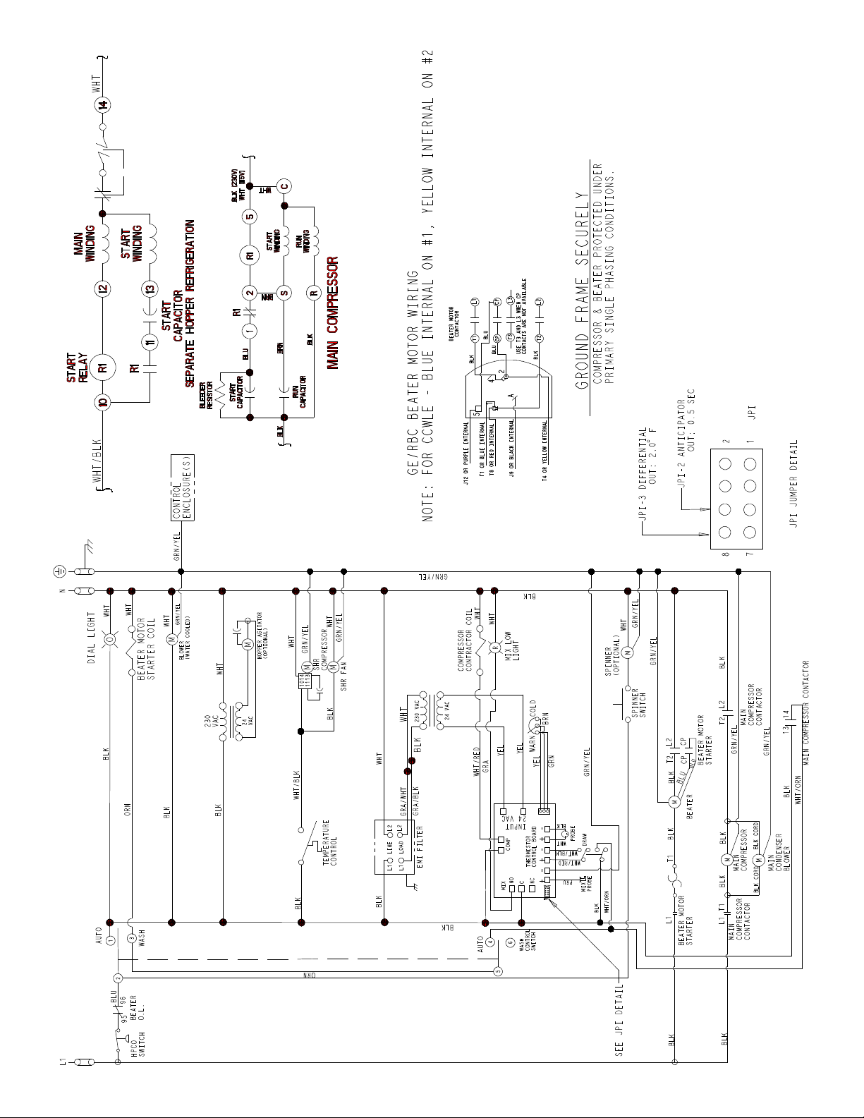
Model 441
062493--40
Rev . 4/08
Page 39
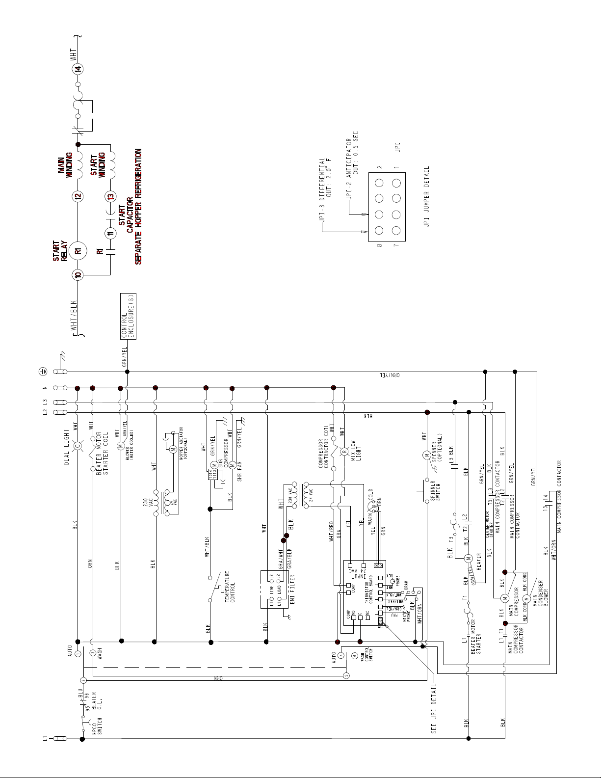
Model 441
062493-58
Rev . 4/08
Page 40
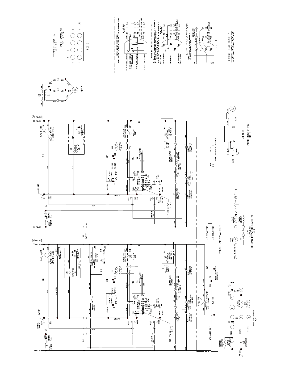
Model 444
063098-27
Rev . 4/08
Page 41
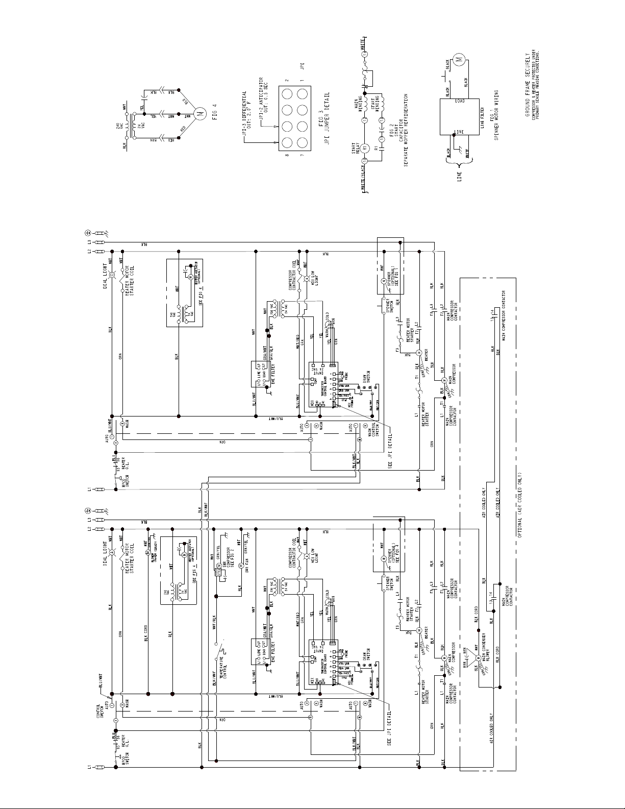
Model 444
063098-33
Rev . 4/08
Page 42
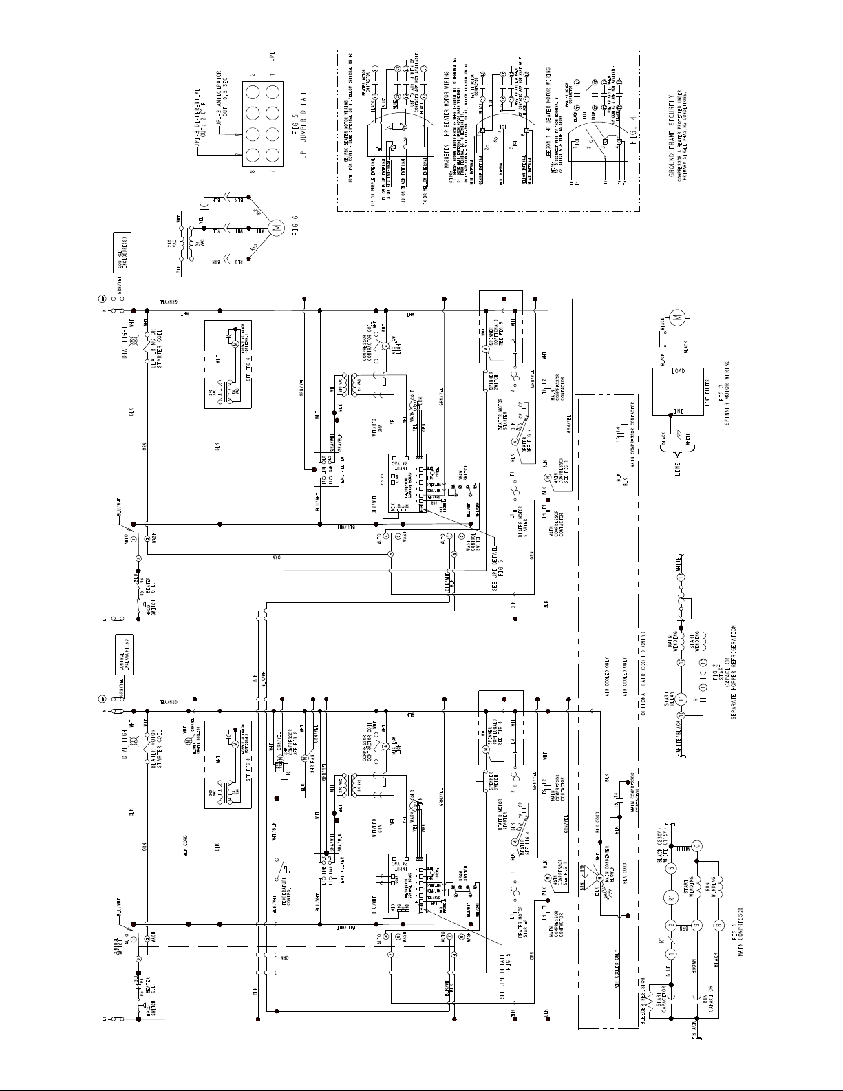
Model 444
063098-40
Rev . 4/08
Page 43
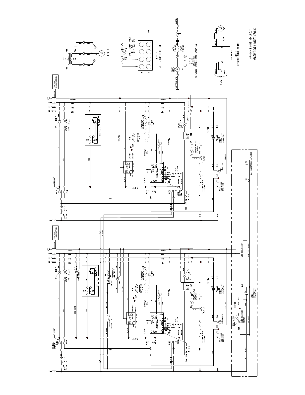
Model 444
063098-58
Rev . 4/08
 Loading...