

Taylor Freezer C606 Operation Manual

Model C606
Combination Freezer
Operating Instructions
059714--M
8/1/05

Complete this page for quick reference when service is required:
Taylor Distributor:
Address:
Phone:
Service:
Parts:
Date of Installation:
Information found on the data label:
Model Number:
Serial Number:
Electrical Specs: Voltage Cycle
Phase
Maximum Fuse Size: A
Minimum Wire Ampacity: A
E May, 2004 Taylor
All rights reserved.
059714-M
Taylor Company
The word Taylor and the Crown design
are registered trademarks in the United States
of America and certain other countries.
a division of Carrier Commercial Refrigeration, Inc.
750 N. Blackhawk Blvd.
Rockton, IL 61072

Table of Contents
Section 1 To th e Installer 1............................................
Installer Safety 1........................................................
Site Preparation 1.......................................................
Air Cooled Units 1.......................................................
Electrical Connections 2.................................................
Beater Rotation 2.......................................................
Refrigerant 3...........................................................
Section 2 To the Operator 4...........................................
Compressor Warranty Disclaimer 4.......................................
Section 3 Safety 5....................................................
Section 4 Operator Parts Id entification 8...............................
Exploded View 8........................................................
Front View 10...........................................................
Syrup Cabinet View 12...................................................
Syrup Pump & Tubes 13..................................................
X57028-XX Pump A. - Mix Simplified - Shake 14.............................
X57029-XX Pump A. - Mix Simplified - Soft Serve 15.........................
X59304 Syrup Line Assembly - Thin Viscosity Syrup 16.......................
X56652 Syrup Line Assembly - Thick Viscosity Shake Syrup (Optional) 17......
X58450 Syrup Line Assembly - Syrup-In-Bag Option 18.......................
Mix Hopper - T op View 19.................................................
Accessories 20..........................................................
X44127 Brush Kit Assembly 22............................................
X53800-BRN/TAN Syrup Pump 23.........................................
Beater Door Assembly - Shake Side 24.....................................
Beater Door Assembly - Soft Serve Side 26.................................
059088 Tray-Parts-Shake Side 27.........................................
059087 Tray-Parts-Soft Serve Side 28......................................
056525 Tray-Parts-Pump-Simplified 29.....................................
Section 5 Important: To the Operator 30.................................
Symbol Definitions 31....................................................
Power Switch 31.........................................................
Vacuum Fluorescent Display 31...........................................
Indicator Lights 31.......................................................
Heat Mode Symbol 32....................................................
Reset Mechanism 32.....................................................
Table of Contents Model C606

Table of Contents - Page 2
Air/Mix Pump Reset Mechanism 32........................................
Adjustable Draw Handle 32...............................................
Shake Fill Level Adjustment 33............................................
VFD Screens 33.........................................................
Manager's Menu 37......................................................
Section 6 Operating Procedures 46.....................................
Equipment Set-Up 46.....................................................
Freezing Cylinder Assembly - Shake Side 46................................
Freezing Cylinder Assembly - Soft Serve Side 50............................
Mix Pump Assembly 54...................................................
Sanitizing - Shake Side 57................................................
Sanitizing - Soft Serve Side 60.............................................
Priming - Shake Side 61..................................................
Priming - Soft Serve Side 62..............................................
Daily Closing Procedures 62..............................................
Daily Opening Procedures 67..............................................
Syrup System 72.........................................................
Syrup Topping Pump 75..................................................
Manual Brush Cleaning 81................................................
Draining Product From T he Freezing Cylinder 82............................
Rinsing 83..............................................................
Cleaning and Sanitizing 83................................................
Disassembly - Shake Side 84..............................................
Disassembly - Soft Serve Side 85..........................................
Brush Cleaning 86.......................................................
Syrup System - Scheduled Maintenance 87.................................
Section 7 Important: Operator Checklist 91..............................
During Cleaning and Sanitizing 91.........................................
Troubleshooting Bacterial Count 91........................................
Regular Maintenance Checks 91...........................................
Winter Storage 92........................................................
Section 8 Troubleshooting Guide 93....................................
Section 9 Parts Replacement Schedule 105...............................
Section 10 Warranty Explanation 106......................................
Section 11 Parts List 107.................................................
Wiring Diagrams 126......................................................
Note: Contin u ing research results in steady improvements; therefore, information
in this manual is subject to change without notice.
Model C606 Table of Contents
Section 1 To the Installer
The following are general installation instructions. For
complete installation details,please seethe check out
card.
Installer Safety
In all areas of the world,equipment shouldbe
installed in accordance with existing local codes.
Please contact your local authorities if you have any
questions.
Care should be taken to ensure that all basic safety
practices are followed during the installation and
servicing activities related to the installation and
service of Taylor equipment.
S Only authorized Taylor service personnel
should perform installation and repairs on
the equipment.
S Authorized service personnel should consult
OSHA Standard 29CFRI910.147 or the
applicable code of the local area for the
industry standards on lockout/tagout
procedures before beginning any installation
or repairs.
S Authorized service personnel must ensure
that the proper PPE is available and worn
when required during installation and
service.
S Authorized service personnel must remove
all metal jewelry, rings, and watches before
working on electrical equipment.
Site Preparation
Review the area the unit is to be installed in before
uncrating the unit making sure that all possible
hazards the user or equipment may come into have
been addressed.
Air Cooled Units
DO NOT obstruct air intake and discharge openings:
Air cooled units require a minimum of 3” (76 mm) of
clearance around all sides of the freezer to allow for
adequate air flow across the condensers. Install the
deflector provided to prevent recirculation of warm
air. Failure to allow adequate clearance can reduce
the refrigeration capacity of the freezer and possibly
cause permanent damage to the compressors.
ForIndoorUseOnly: This unitisdesigned tooperate
indoors, under normal ambient temperatures of
70_-75_F(21_-24_C). The freezer has successfully
performed in high ambient temperatures of
104_(40_C) at reduced capacities.
This unit must NOT be installed in an area
where a water jet or hose can be used. NEVER use a
water jet or hose to rinse or clean the unit. Failure to
follow this instruction may result in electrocution.
The mainpower supply(s)to thefreezer must
be disconnected prior to performing any repairs.
Failure to follow this instruction may result in personal
injury or death from electrical shock or hazardous
moving parts as well as poor performance ordamage
to the equipment.
Note:Allrepairsmustbeperformedbyan
authorized Taylor Service Technician.
This unit has many sharp edges that can
cause severe injuries.
Model C606 To the Installer
to avoid the hazardof tipping. Extremecare should be
taken in movingthis equipmentfor anyreason. Twoor
more persons are required to safely move this unit.
Failure to comply may result in personal injury or
equipment damage.
Uncrate theunit andinspect itfor damage. Report any
damage to your Taylor Distributor.
This piece of equipment is made in the USA and has
USA sizes of hardware. All metric conversions are
approximate and vary in size.
1
This unit must be installed on a level surface
081208
Electrical Connections
In the United States, this equipment is intended to be
installed in accordance with the National Electrical
Code (NEC), ANSI/NFPA 70-1987. The purpose of
the NEC code is the practicalsafeguarding of persons
and property from hazards arising from the use of
electricity. This code contains provisions considered
necessary for safety. In all other areas of the world,
equipment should be installed in accordance with the
existing local codes. Please contact your local
authorities.
FOLLOW YOUR LOCAL ELECTRICAL CODES!
Each unit requires one power supply for each data
label on the unit. Check the data label on the freezer
for fuse, circuit ampacity and other electrical
specifications. Refer to the wiring diagram provided
inside of the electrical box, for proper power
connections.
CAUTION: THIS EQUIPMENT MUST BE
PROPERLY GROUNDED! FAILURE TO DO SO
CAN RESULT IN SEVERE PERSONAL INJURY
FROM ELECTRICAL SHOCK!
Appliances that arepermanentlyconnected to
fixed wiring and for which leakage currents may
exceed 10 mA, particularly when disconnected or not
used for long periods,or duringinitial installation, shall
have protective devices such as a GFI, to protect
against the leakage of current, installed by the
authorized personnel to the local codes.
Supply cords used with this unit shall be
oil-resistant, sheathed flexible cable not lighter than
ordinary polychloropreneor other equivalent synthetic
elastomer-sheathed cord (Code designation 60245
IEC 57) installed with the proper cord anchorage to
relieve conductors from strain, including twisting, at
the terminals and protect the insulation of the
conductors from abrasion.
Beater Rotation
DONOT operate this freezer withlarger fuses
than specified on the unit data label. Failure to follow
this instruction may result in electrocution or damage
to the machine.
This unit is provided with an equipotential
groundinglug that isto be properlyattached to therear
oftheframe by the authorizedinstaller.The installation
location is marked by the equipotential bonding
symbol (5021 of IEC 60417-1) on both the removable
panel and the equipments frame.
Stationary appliances whichare notequipped
with a power cord and a plug or another device to
disconnect the appliance from the power source must
have an all-pole disconnecting device with a contact
gap of at least 3mm installed in the external
installation.
080902
Beater rotation must be clockwise as viewed
looking into the freezing cylinder.
Note: The following procedures shouldbe performed
by a trained service technician.
To correct the rotation on a three-phase unit,
interchange any two incoming power supply lines at
freezer main terminal block only.
To correct rotation on a single-phase unit, change
the leads inside the beater motor. (Follow the
diagram printed on the motor.)
Electrical connections are made directly to the
terminal block. The terminal block is provided in the
splice box located behind the right side panel.
2
Model C606To the Installer
Refrigerant
In consideration of our environment, Taylor
proudly usesonly earth friendlyHFC refrigerants.The
HFC refrigerant used in this unit is R404A. This
refrigerant is generally considered non-toxic and
non-flammable, with an Ozone Depleting Potential
(ODP) of zero (0).
However, any gas under pressure is potentially
hazardous and must be handled with caution.
NEVER fill any refrigerant cylinder completely with
liquid. Filling the cylinder to approximately 80% will
allow for normal expansion.
Refrigerant liquid sprayed onto the skin may
cause serious damage to tissue. Keep eyes and skin
protected. If refrigerant burns should occur, flush
immediately withcoldwater. Ifburns aresevere, apply
ice packs and contact a physician immediately.
Taylor reminds technicians to be cautious of
government laws regarding refrigerant recovery,
recycling, and reclaiming systems. If you have any
questions regarding these laws, please contact the
factory Service Department.
WARNING: R404A refrigerant used in
conjunction with polyolester oils is extremely moisture
absorbent. When opening a refrigeration system, the
maximumtime the systemisopen must notexceed15
minutes. Cap all open tubing to prevent humid air or
water from being absorbed by the oil.
080902
Model C606 To the Installer
3

Section 2 To the Operator
The freezer you have purchased has been carefully
engineered and manufactured to give you
dependable operation. The Taylor freezer, when
properly operated and cared for, will produce a
consistent quality product. Like all mechanical
products, this machine will require cleaning and
maintenance. A minimum amount of care and
attention is necessary if the operating procedures
outlined in this manual are followed closely.
This Operator's Manual should be read before
operating or performing any maintenance on your
equipment.
Your Taylor freezer will NOT eventually compensate
and correct for any errors during the set-up or filling
operations. Thus, the initial assembly and priming
procedures are of extreme importance. It is strongly
recommended that all personnel responsible for the
equipment's operation review these procedures in
order to be properly trained and to make sure that
there is no confusion.
In the event that you should require technical
assistance, please contact your local authorized
Taylor Distributor.
Note: Warranty is valid only if the parts are
authorized Taylor parts, purchased from an
authorized Taylor Distributor, and the required
service work is provided by an authorized Taylor
service technician. Taylor reserves the right to deny
warranty claims on equipment or parts if
non-approved parts or refrigerant were installed in
the machine, system modifications were performed
beyond factory recommendations, or it is determined
that the failure was caused by neglect or abuse.
Note: Con st ant research results in steady
improvements; therefore, information in this
manual is subject to change without notice.
If the crossed out wheeled bin symbol is
affixed to this product, it signifies that this product is
compliant with the EU Directive as well as other
similar legislation in effect after August 13, 2005.
Therefore, it must be collected separately after its
use is completed, and cannot be disposed as
unsorted municipal waste.
The user is responsible for returning the product to
the appropriate collection facility, as specified by
your local code.
For additional information regarding applicable local
laws, please contact the municipal facility and/or
local distributor.
Compressor Warranty Disclaimer
The refrigeration compressors on this machine are
warranted for the term indicated on the warranty
card accompanying this machine. However, due to
the Montreal Protocol and the U.S. Clean Air Act
Amendments of 1990, many new refrigerants are
being tested and developed, thus finding their way
into the service industry.
Some of these new refrigerants are being advertised
as “drop-in” replacements for numerous
applications. It should be noted that, in the event of
ordinary service to this machine’s refrigeration
system, only the refrigerant specified on the
affixed data label should be used. The
unauthorized use of alternate refrigerants will void
your compressor warranty. It will be the owner’s
responsibility to make this fact know to any
technician he employs.
It should also be noted that Taylor does not warrant
the refrigerant used in its equipment. For example, if
the refrigerant is lost during the course of ordinary
service to this machine, Taylor has no obligation to
either supply or provide its replacement either at
billable or unbillable terms. Taylor does have the
obligation to recommend a suitable replacement if
the original refrigerant is banned, obsoleted, or no
longer available during the five year warranty of the
compressor.
Taylor will continue to monitor the industry and test
new alternates as they are being developed. Should
a new alternate prove, through our testing, that it
would be accepted as a drop-in replacement, then
the above disclaimer would become null and void.
To find out the current status of an alternate
refrigerant as it relates to your compressor warranty,
call the local Taylor Distributor or the Taylor factory.
Be prepared to provide the Model/Serial Number of
the unit in question.
080902
4
Model C606To the Operator
Section 3 Safety
WeatTaylor Company areconcernedabout thesafety
of the operator when he or she comes in contact with
the freezer and its parts. Taylor has gone to extreme
efforts to design and manufacture built-in safety
features to protectbothyouandtheservicetechnician.
As anexample, warning labels havebeen attached to
thefreezer to furtherpointoutsafetyprecautionstothe
operator.
IMPORTANT - Failure to adhere to the
following safety precautions may result in severe
personal injury or death. Failure to comply with
these warnings may damage the machine and its
components. Component damage will result in
part replacement expense and service repair
expense.
DO NOT operatethefreezer withoutreading
this Operator Manual. Failure to follow this instruction
may result in equipment damage, poor freezer
performance, health hazards, or personal injury.
This unit is provided with an equipotential
groundinglug that isto be properlyattached to therear
oftheframe by the authorizedinstaller.The installation
location is marked by the equipotential bonding
symbol (5021 of IEC 60417-1) on both the removable
panel and the equipments frame.
S DO NOT attempt any repairs unless the
main power supply to the freezer has been
disconnected.
S Stationary appliances which are not
equipped with a power cord and a plug or
another device to disconnect the appliance
from the power source must have an all-pole
disconnecting device with a contact gap of
at least 3mm installed in the external
installation.
S Appliances that are permanently connected
to fixed wiring and for which leakage
currents may exceed 10 mA, particularly
when disconnected or not used for long
periods, or during initial installation, shall
have protective devices such as a GFI, to
protect against the leakage of current,
installed by the authorized personnel to the
local codes.
S Supply cords used with this unit shall be
oil-resistant, sheathed flexible cable not
lighter than ordinary polychloroprene or
other equivalent synthetic
elastomer-sheathed cord (Code designation
60245 IEC 57) installed with the proper cord
anchorage to relieve conductors from strain,
including twisting, at the terminals and
protect the insulation of the conductors from
abrasion.
Failure to follow these instructions may result in
electrocution. Contact your local authorized Taylor
Distributor for service.
DO NOT use a water jet to clean or rinse the
freezer. Failure to follow these instructions may result
in serious electrical shock.
S DO NOT allow untrained personnel to
operate this machine.
S DO NOT operate the freezer unless all
service panels and access doors are
restrained with screws.
S DO NOT remove any internal operating
S DO NOT operate the freezer unless it is
properly grounded.
S DO NOT operate the freezer with larger
fuses than specified on the freezer data
label.
Model C606 Safety
Failuretofollow these instructionsmayresult in severe
personal injury from hazardous moving parts.
5
parts (example: freezer door, beater,
scraper blades, etc.) unless all control
switches are in the OFF position.
080902

This unit has many sharp edges that can
cause severe injuries.
S DO NOT put objects or fingers in the door
spout. This may contaminate the product
and cause severe personal injury from blade
contact.
S USE EXTREME CAUTION when removing
the beater asssembly. The scraper blades
are very sharp.
S CAUTION-SHARP EDGES: Two people are
required to handle the cup/cone dispenser.
Protective gloves must be worn and the
mounting holes must NOT be used to lift or
hold the dispenser. Failure to follow this
instruction can result in personal injury to
fingers or equipment damage.
Cleaning and sanitizing schedules are
governed by your state or local regulatory agencies
and must be followed accordingly. Please refer to the
cleaning section of this manual for the proper
procedure to clean this unit.
This freezer must be placed on a level
surface. Failureto comply mayresultin personal injury
or equipment damage.
This freezer is designed to operate indoors, under
normal ambient temperatures of 70_-75_F
(21_-24_C). The freezer has successfully performed
in high ambient temperatures of 104_F(40_C) at
reduced capacities.
DO NOT obstruct air intake and discharge openings:
3” (76 mm) minimum air space all sides is required.
Install the deflector provided to prevent recirculation
of warm air. Failure to follow this instruction may
cause poor freezer performance and damage to the
machine.
NOTICE all warning labels that have been attached
to the freezer to further point out safety precautions
to the operator.
NOISE LEVEL: Airborne noise emission does not
exceed 78 dB(A) when measured at a distance of
1.0 meter from the surface of the machine and at a
height of 1.6 meters from the floor.
080902
6
Model C606Safety

Notes:
Model C606 Safety
7
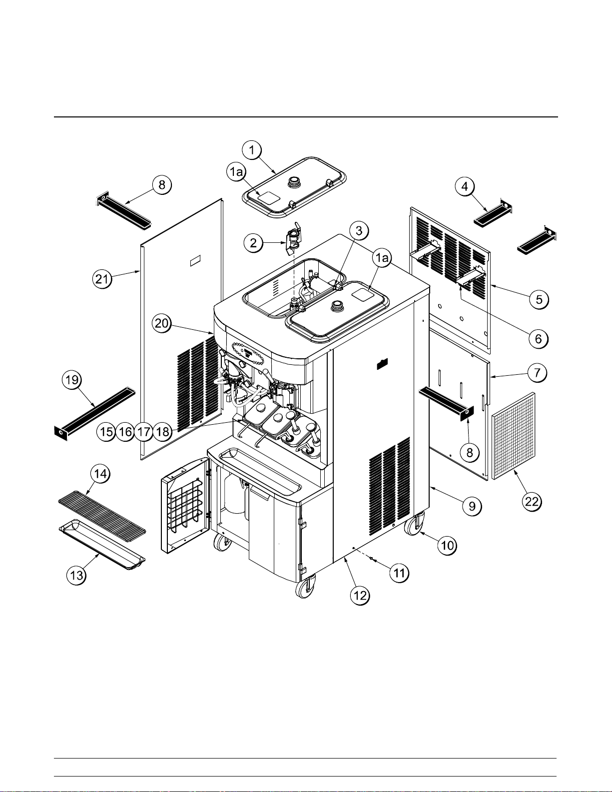
Section 4 Operator Parts Identification
ExplodedView
080723
Figure 1
8
Model C606Operator Parts Identification

Exploded View (See Figure 1)
ITEM DESCRIPTION PART NO.
1 Cover-Hopper*Black* 053809-1
2 AgitatorAssembly X44797
3 Pin-Retaining HopperCover 043934
4 Pan-Drip-Rear 8-3/4” L (22.2 cm) X56003
5 Panel-Rear-Upper 055958
6 Guide A.-Drip Pan Mix Pump X48228
7 Panel-Rear-Lower 055959
8 Pan-Drip-Side 12-3/4” L (32.4 c m) X56005
Trim-Corner-Rear Right Side 056692
9
Trim-Corner-RearLeft Side 056693
10 Caster-4” 044106
11 Screw-1/4- 20 x 3/8 011694
ITEM DESCRIPTION PART NO.
12 Panel-SideRight 055950
13 Tray-Drip 033812
14 Shield-Splash 033813
15 Lid-SyrupJar 042706
16 Jar-Syrup - Plastic Shallow 036573
17 Jar-Syrup - Stainless Shallow 036574
18 Ladle-1 oz. (30ml.) 033637-1
19 Pan-Drip19-3/4” Long (50.2cm) 035034
20 Plate-Dec. 056131-1
21 Panel-SideLeft 055957
22 Filter-Air 18.0 L x 13.5 H x .70 W 052779-3
Model C606 Operator Parts Identification
9
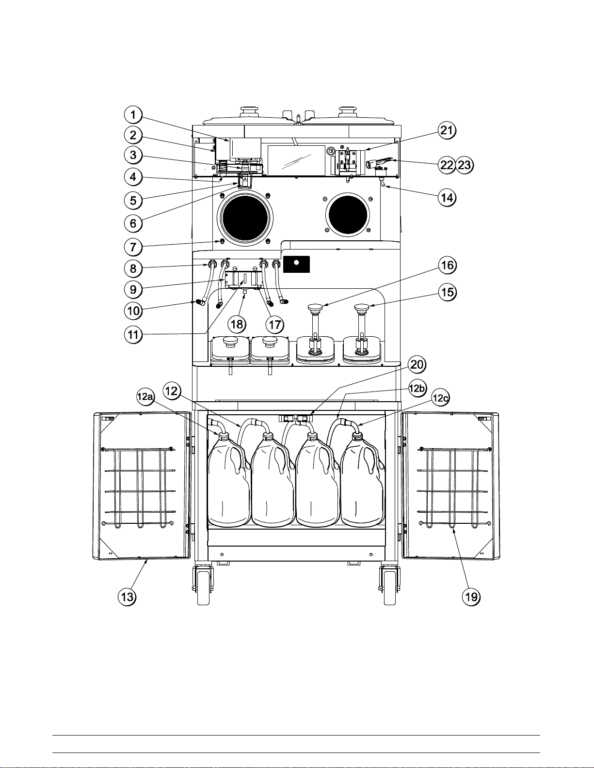
Front View
050112
Figure 2
10
Model C606Operator Parts Identification
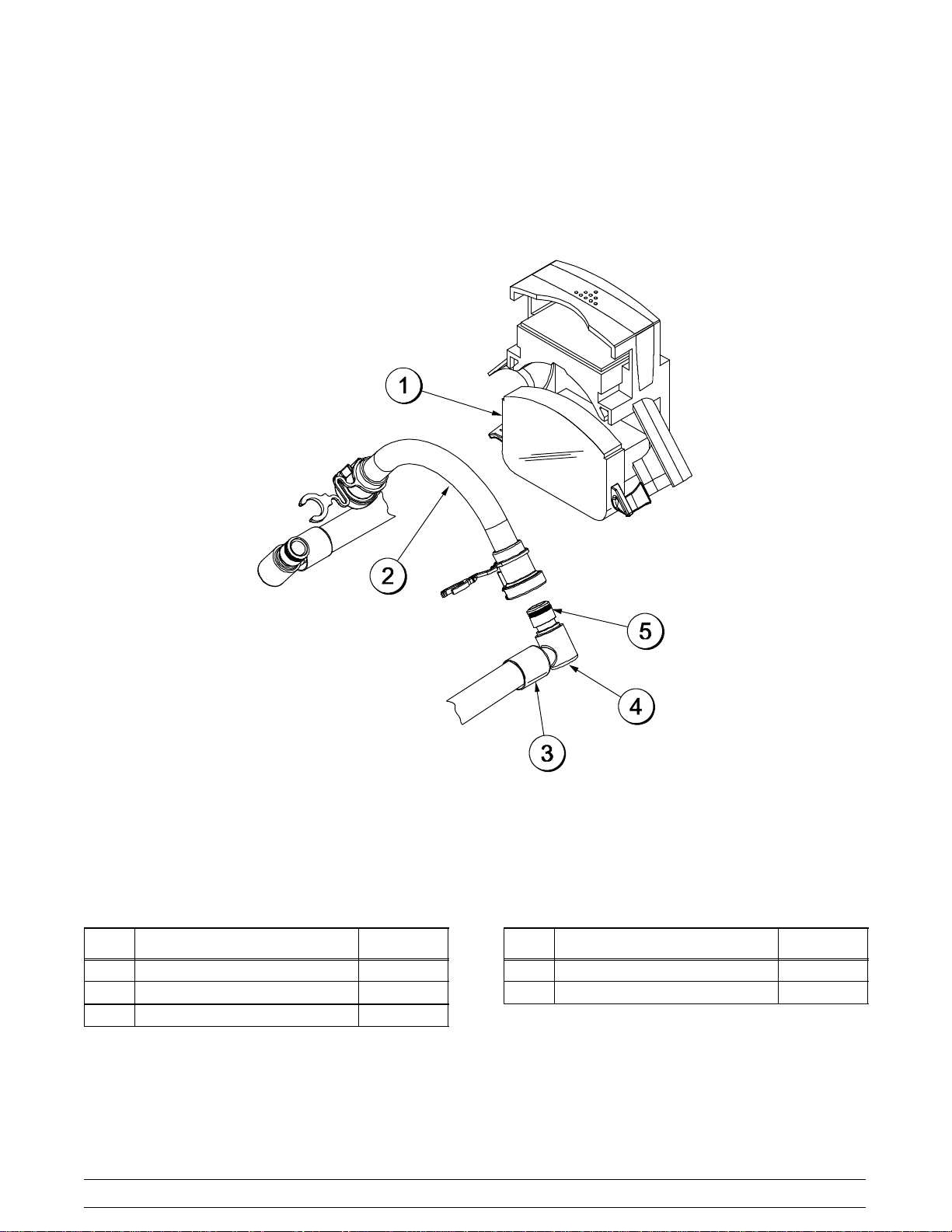
Front View (See Figure 2)
ITEM DESCRIPTION PART NO.
1 Motor A.-Spinner X35584SER2
2 Solenoid-DrawValve 059462
3 Coupling-Flexible W/Screws 020108
4 Bumper-Recessed 057910
4a Screw-1/4-20x 3/4 057911
5 Bracket-Coupling Actuator 056620
6 Coupling A.-Drive Spinner X20329
7 Stud-Nose Cone 055987
8 Fitting-Panel Mount QD 056674
9 Clip-Spring Cup Holder 055192
Line A.-Syrup Door X59304
10
Line A.-Syrup Door (Optional-
for thick viscosity syrupsystem)
11 Sensor A.-Pyroelectric 6” X59268
FittingA.-SyrupJug
12
(pick up tube assembly)
*12 Line A.-Syrup
(forbag syrupsystem)
X56652
X53353-BLU
X53353-BRN
X53353-RED
X53353-WHT
X58450
ITEM DESCRIPTION PART NO.
053040-BLU
12a Cap-Ultimate Syrup
12b Hose-Beverage 053052-36
12c Tube A.-Syrup Pick Up X53175
*12d Ferrule-.625 ID 053036
13 Door A.-Cabinet X58607
14 Switch-Toggle-Power 054809
15 Pump A.-Syrup- Heated
(Chocolate)
16 Pump A.-Syrup- Heated
(Caramel)
17 Holder-CupShake 056008
18 Screw-Adjustment 051574
19 Rack-Syrup Cabinet Door 059144
20 Latch-Cabinet 062178
21 Switch-Lever-SPST-10A 028889
22 Holder-Fuse-In Line-Type HLR 045606
23 Fuse-12A In Line-NonDelay 062431
* Pin-Roll- .094 x .562 015971
*Not Shown
053040-BRN
053040-RED
053040-WHT
X53800-BRN
X53800-TAN
041008
Model C606 Operator Parts Identification
11
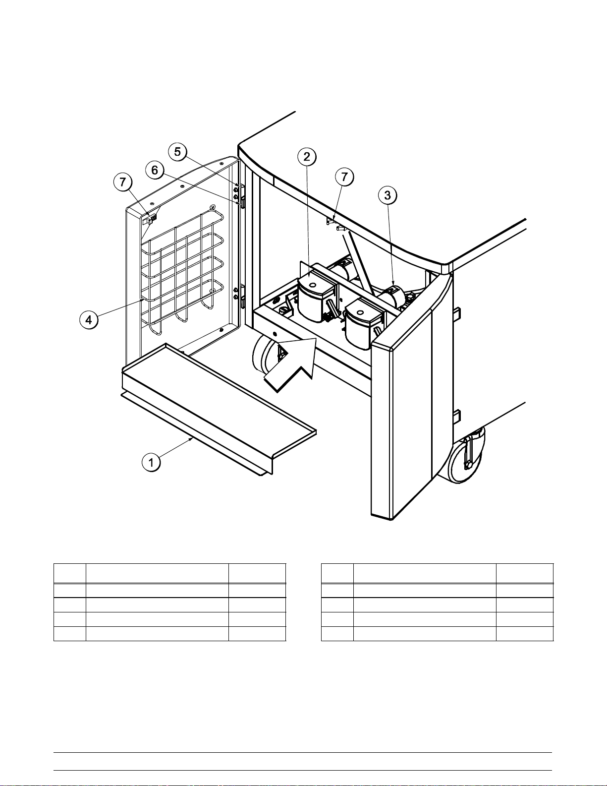
Syrup Cabinet View
ITEM DESCRIPTION PART NO.
1 Shelf-Syrup 056016
2 Pump-Peristaltic 052916
3 Motor-Gear161 RPM 058725
4 Rack-Syrup Cabinet Door 059144
Figure 3
12
ITEM DESCRIPTION PART NO.
5 Block-Hinge 058613
6 Block-Hinge 058614
7 Latch-Cabinet 062178
* Pin-Hinge 058615
*Not Shown
Model C606Operator Parts Identification
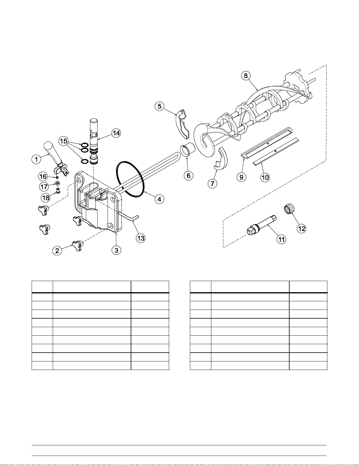
Syrup Pump & Tubes
Figure 4
ITEM DESCRIPTION PART NO.
1 Pump-Peristaltic 052916
2 Kit A.-Peristaltic Pump Tube X54978
3 Ferrule-.625 ID 053036
Model C606 Operator Parts Identification
13
ITEM DESCRIPTION PART NO.
4 Fitting-Peristaltic Pump 054526
5 O-Ring 1/2 OD x .070 024278
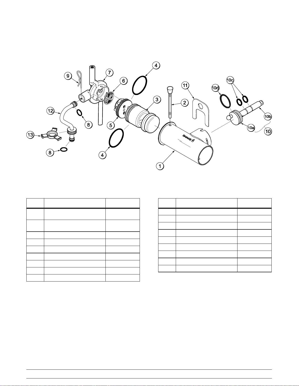
X57028-XX Pump A. - Mix Simplified - Shake
Figure 5
ITEM DESCRIPTION PART NO.
1-7 Pump A.-Mix Simplified
Shake
1 Cylinder-Pump-Hopper-
Shake
2 Pin A.-Retaining X55450
3 Piston 053526
4 O-Ring 2-1/8”OD- Red 020051
5 Cap-Valve 056873-XX
6 Gasket-Simplified Pump 053527
7 Adaptor-Mix Inlet Shake-Blue 054944
8 O-Ring-11/16 OD - Red 016132
X57028-XX
057944
ITEM DESCRIPTION PART NO.
9 Pin-Cotter 044731
10 Shaft A.-Drive Mix Pump X41947
10a Crank-Drive 039235
10b Shaft-Drive 041948
10c O-Ring-Drive Shaft 048632
10d O-Ring 1-3/4 008904
11 Clip-Mix Pump Retainer 044641
12 Tube A.-Feed-HopperShake X55973
13 Ring-Check .120 OD 056524
*Note:Items 8 - 13 are not included in X57028-XX.
14
Model C606Operator Parts Identification
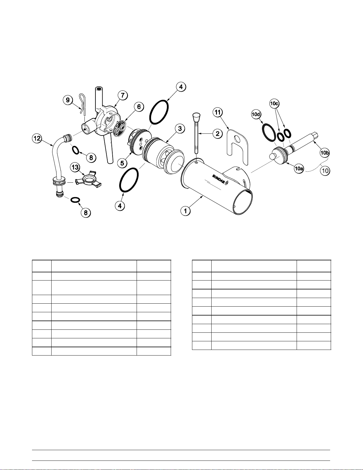
X57029-XX Pump A. - Mix Simplified - Soft Serve
ITEM DESCRIPTION PART NO.
1-7 Pump A.-Mix Simplified Soft Srv X57029-XX
1 Cylinder-Pump-Hopper-Soft
Serve
2 Pin A.-Retaining X55450
3 Piston 053526
4 O-Ring 2-1/8” OD - Red 020051
5 Cap-Valve 056874-XX
6 Gasket-Simplified Pump Valve 053527
7 Adaptor-Mix Inlet Soft Serve-Red 054825
8 O-Ring - 11/16 OD - Red 016132
057943
Figure 6
ITEM DESCRIPTION PART NO.
9 Pin-Cotter 044731
10 Shaft A.-Drive-Mix Pump-Hopper X41947
10a Crank-Drive 039235
10b Shaft-Drive 041948
10c O-Ring - Drive Shaft 048632
10d O-Ring 1-3/4 008904
11 Clip-Mix Pump Retainer 044641
12 Tube A.-Feed Hopper-Soft Serve X55974
13 Ring-Check .120 OD 056524
*Note:Items 8 - 13 are not included in X57029-XX.
Model C606 Operator Parts Identification
15

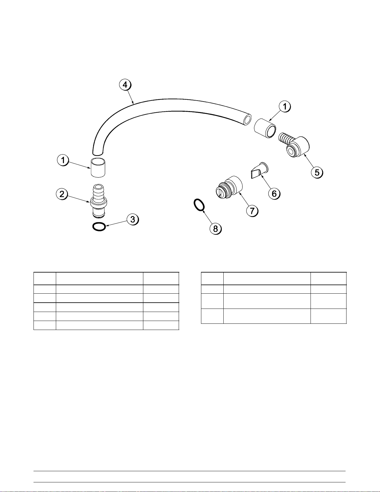
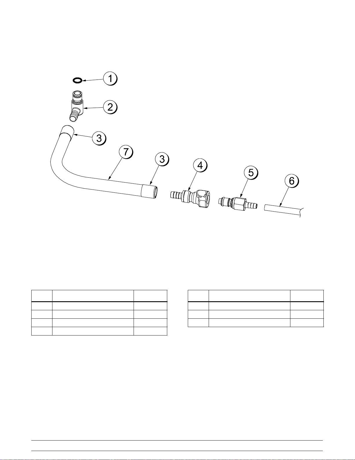
X59304 Syrup Line Assembly - Thin Viscosity Syrup
ITEM DESCRIPTION PART NO.
1 Ferrule-.650 ID 029834
2 Fitting-Barb 056675
3 O-Ring 500205
4 Tube-Vinyl 500038-9
5 Fitting-Syrup Elbow 056651
Figure 7
ITEM DESCRIPTION PART NO.
6 Valve-CheckDuckbill 500598
7 Fitting-Syrup Nose (SmallSlot) 056649
8 O-Ring-11 mm Green (Syrup
Hole Plug)
053890
16
Model C606Operator Parts Identification
X56652 Syrup Line Assembly - Thick Viscosity Shake Syrup (Optional)
ITEM DESCRIPTION PART NO.
1 Ferrule-.625 ID 053036
2 Fitting-Barb 056675
3 O-Ring 500205
4 Hose-Beverage 053052-9
5 Fitting-Syrup Elbow 056651
Figure 8
ITEM DESCRIPTION PART NO.
6 Valve-CheckDuckbill 500598
7 Fitting-Syrup Nose
(Large Slot)
8 O-Ring-11 mm Green (Syrup
Hole Plug)
056650
053890
Model C606 Operator Parts Identification
17
X58450 Syrup Line Assembly - Syrup-In-Bag Option
ITEM DESCRIPTION PART NO.
1 O-Ring-1/2 OD x .070 024278
2 Fitting-Male 054526
3 Ferrule-.625 ID NP Brass 053036
4 Coupling-QD Female 3/8 Barb 058451
Figure 9
ITEM DESCRIPTION PART NO.
5 Coupling-QD Male 1/4 Barb 058452
6 Tube-Vinyl3/16 ID x 1/16 Wall 020940-8
7 Hose-Beverage3/8 ID 053052-36
18
Model C606Operator Parts Identification
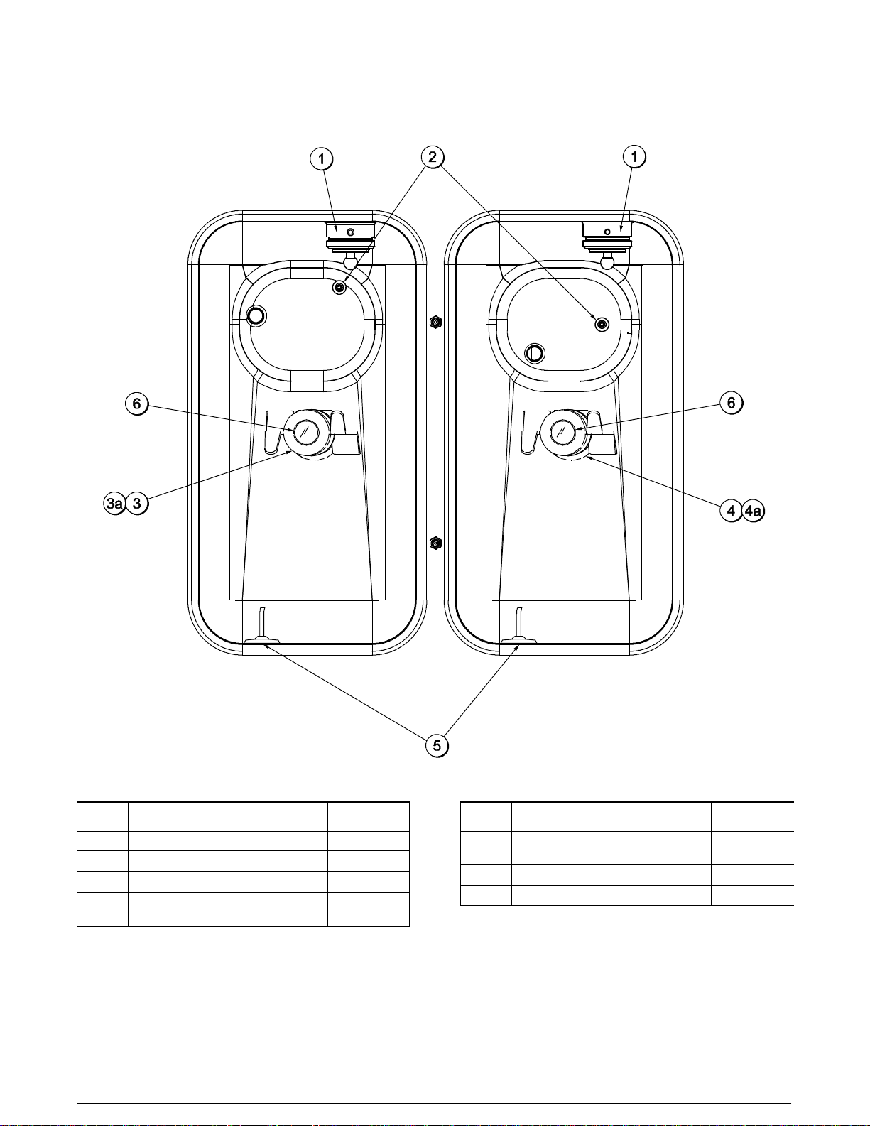
Mix Hopper - Top View
Figure 10
ITEM DESCRIPTION PART NO.
1 Sleeve A.-Mix Pump X44761
2 Probe A.-Mix Out X41348
3 Housing A. Agitator(Shake) X51664
3a4aMagnet A.-Agitator-Inner X41733
Model C606 Operator Parts Identification
19
ITEM DESCRIPTION PART NO.
4 Housing A.-Agitator
(SoftServe)
5 Probe A.-Mix Low X42077
6 Cap-Magnet 044796
X51661
050128
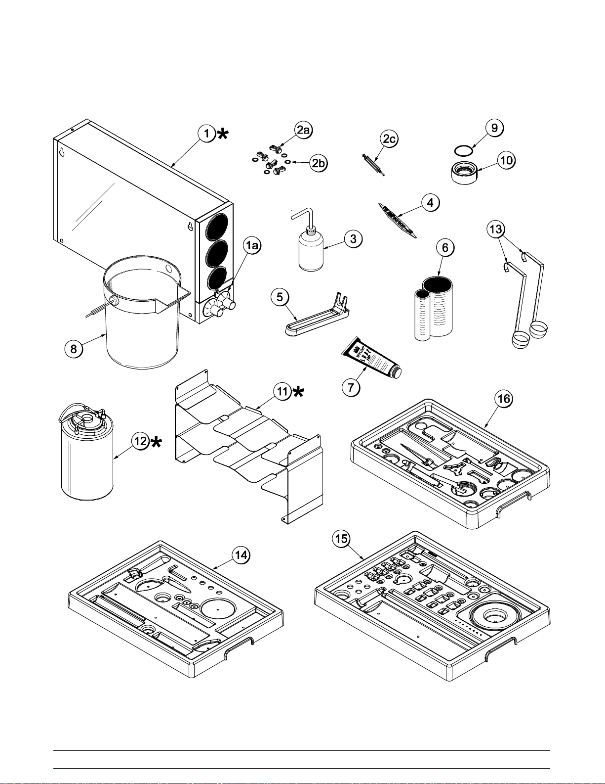
Accessories
050128
Figure 11
20
Model C606Operator Parts Identification
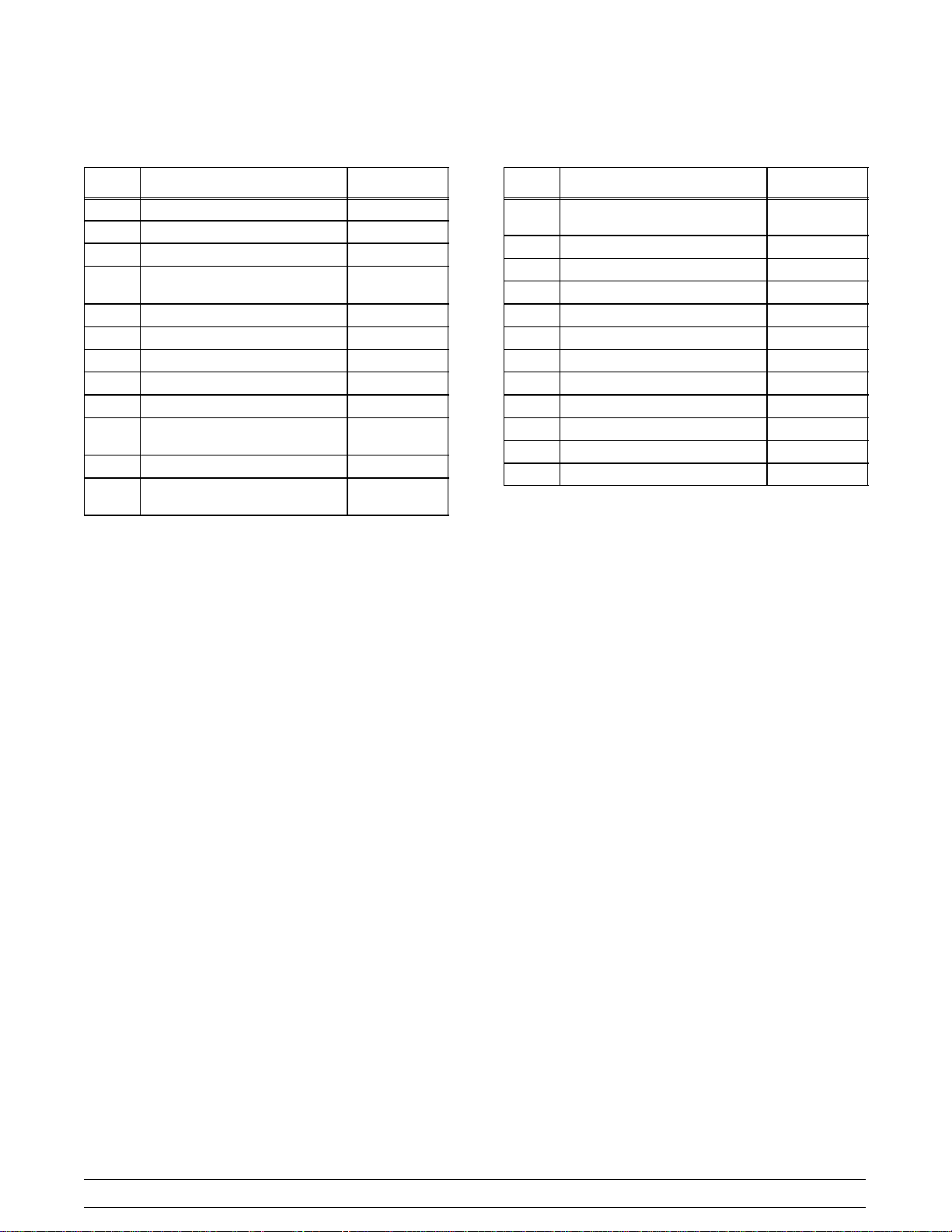
Accessories (See Figure 11)
ITEM DESCRIPTION PART NO.
*1 Dispenser A.-Cone X56121
1a Baffle-RubberCone 052193
2a Plug-Syrup Port 053867
2b O-Ring-11mm Green
(Syrup Hole Plug)
2c Tool-SealInstall-Remove 035460
3 Bottle-Plastic Wash 044818
4 Tool-O-Ring Removal 048260-WHT
5 Tool-Shaft-Drive-Pump-Hopper 057167
6 Cup-DividedSyrup 017203
7 Lubricant-Taylor
Hi-Performance
8 Pail-Mix 10 Qt. 013163
9 O-Ring - 1-11/16 OD
(Draw Valve Cap)
053890
048232
041923
ITEM DESCRIPTION PART NO.
10 Cap A.-Valve-Draw
(Spout Cap)
*11 Tray A.-Syrup (Syrup in Bag) X59143
*12 Tank-Syrup 4 Quart 056673
13 Ladle - 1 Ounce 033637-1
14 Tray-Parts Soft Serve Side 059087
15 Tray-Parts Shake Side 059088
16 Tray-Parts-Pump-Simplified 056525
** Kit A.-Peristaltic Pump Tube X54978
** Kit A.-Topping Pump Spares X53795
** Kit A.-Tune Up C606 X49463-59
** Deflector-BlowerExhaust 047912
** Box-Tool15” Plastic 058669
* Optional
** Not Shown
X54704
050128
Model C606 Operator Parts Identification
21
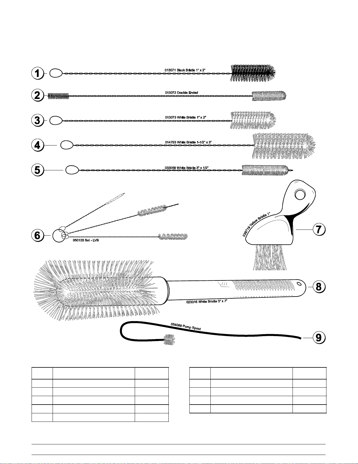
X44127 Brush Kit Assembly
ITEM DESCRIPTION PART NO.
1 Black Bristle Brush 013071
2 Double End Brush 013072
3 WhiteBristleBrush(1”x2”) 013073
4 WhiteBristle Brush (1-1/2”x 3”) 014753
5 WhiteBristle Brush (1/2” x 3”) 033059
Figure 12
22
ITEM DESCRIPTION PART NO.
6 Brush Set (3) 050103
7 YellowBristleBrush 039719
8 White Bristle (3” x 7”) 023316
9 Brush-PumpSpout 054068
Model C606Operator Parts Identification
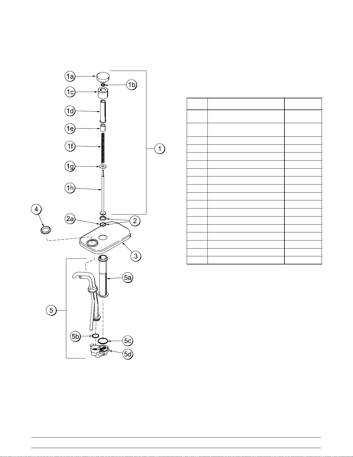
X53800-BRN/TAN Syrup Pump
ITEM DESCRIPTION PART NO.
1 PlungerAssembly X36576-TAN
X36576-BRN
1a Knob-Plunger 032762-TAN
032762-BRN
1b O-Ring-Knob 016369
1c Nut-Plunger 036577
1d Tube-Plunger 032757
1e Insert-Plunger 032758
1f Spring-Plunger-SyrupPump 032761
1g Washer-Nylon 032760
1h Plunger 036578
2 SealAssembly X33057
2a O-Ring - Plunger 019330
3 Lid-Pump 036579
4 Nut-Spout 039680
5 Pump A.-Syrup Heated X53798-SER
5a Cylinder-SyrupPump 051065
5b O-Ring-OutletTube 048148
5c O-Ring-PlungerTube 048149
5d KitA.-ValveCaptured Ball 048166-001
Figure 13
Model C606 Operator Parts Identification
23
Beater Door Assembly - Shake Side
041008
Figure 14
24
Model C606Operator Parts Identification
Beater Door Assembly - Shake Side (See Figure 14)
ITEM DESCRIPTION PART NO.
1 Seal-Drive Shaft 032560
2 Shaft-Beater 7 Qt. Fluted
Blade
3 Blade-Scraper-16” 041103
4 Bearing-Door Front 1.390 OD 055605
5 BeaterA.-7 Qt. Fluted Blade X50958
6 O-Ring6” - Freezer Door 033493
7 Door A.-Shake Side X55825SER2
8 Nut-Stud 055989
9 O-Ring-Syrup Port 11mmID x
2mm Green
050985
053890
ITEM DESCRIPTION PART NO.
10 Plug-Syrup Port 053867
11 Retainer-Syrup Valve 054554
12 O-Ring - 1-1/16 OD x .139W
(Draw Valve)
13 Seal-Spinner Shaft 036053
14 Spinner 034054
15 Blade A.-Spinner
Aluminum-HT
16 Cap-Restrictor 033107
17 Valve A.-Draw X57169
020571
X59331
041008
Model C606 Operator Parts Identification
25
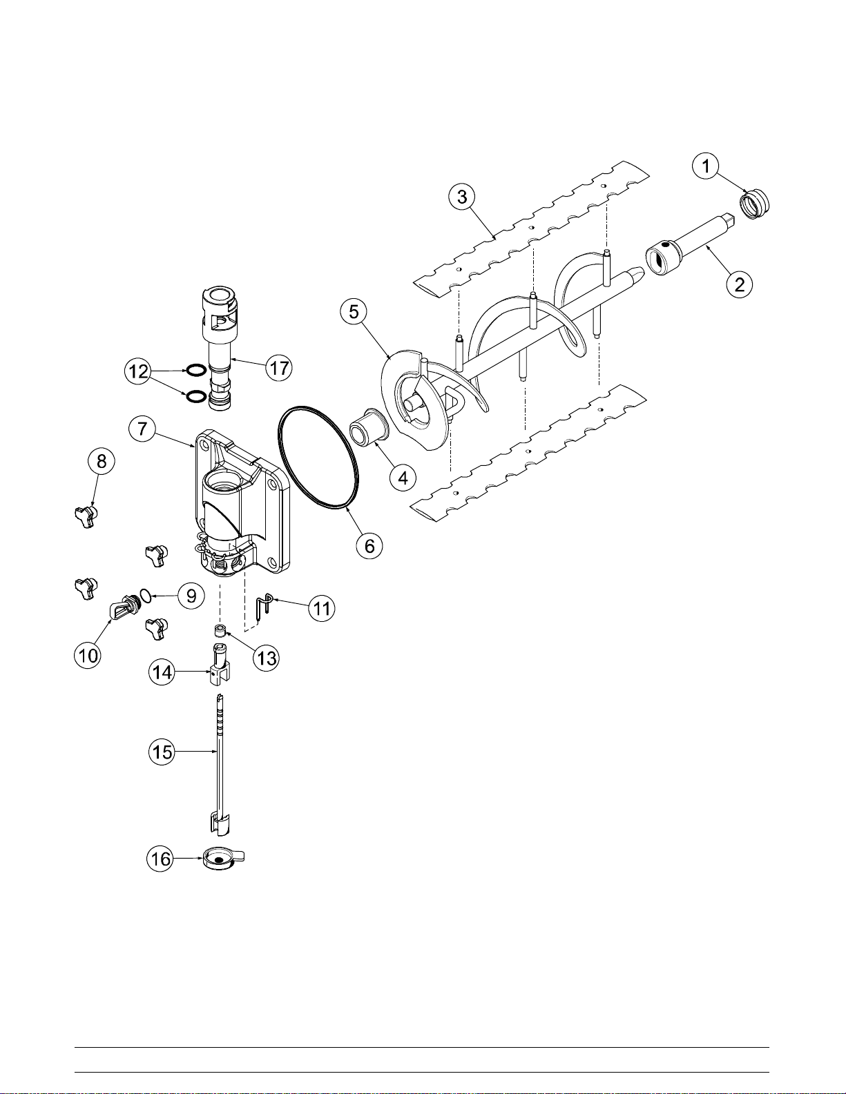
Beater Door Assembly - Soft Serve Side
ITEM DESCRIPTION PART NO.
1 Handle A.-Draw X56421-1
2 Stud Nut 055989
3 Door A.-w/Baffle X57332-SER
4 Gasket (Freezer Door) 048926
5 Shoe-FrontHelix-Rear 050346
6 Bearing-Front 050348
7 Shoe-FrontHelix-Front 050347
8 BeaterAssembly X46231
9 Blade-Scraper 046235
Figure 15
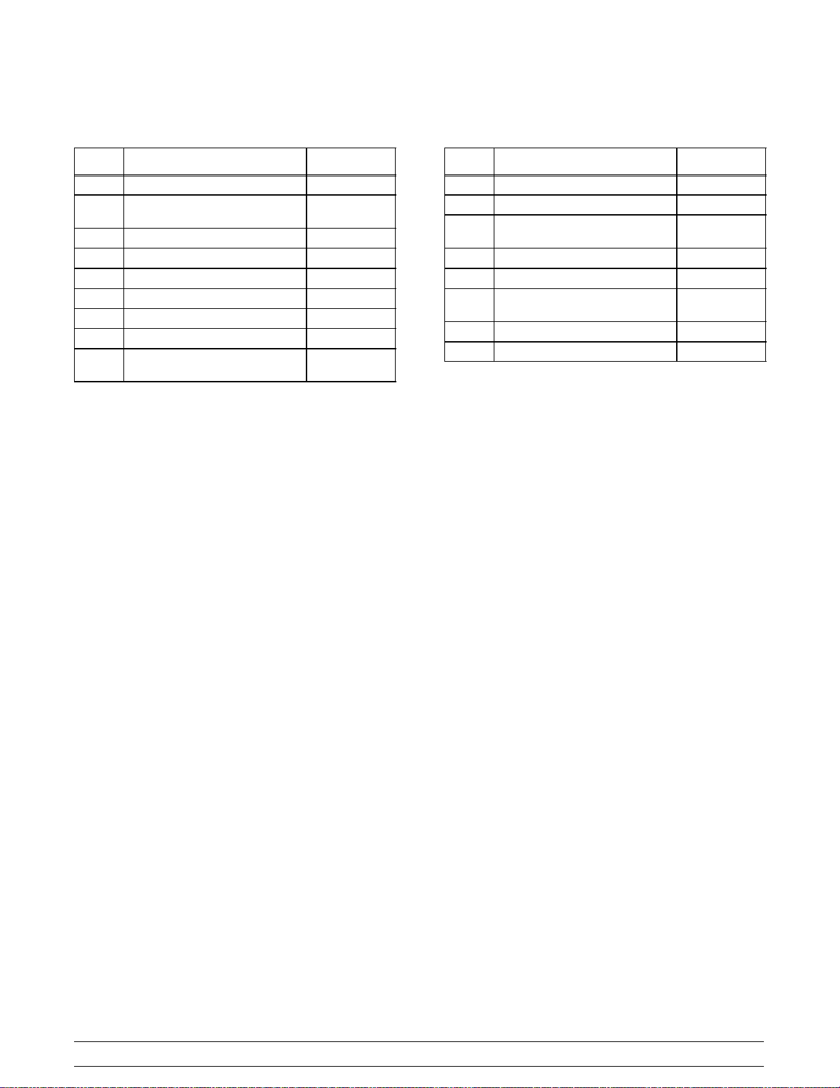
ITEM DESCRIPTION PART NO.
10 Clip-Scraper Blade 046236
11 DriveShaft 032564
12 Seal-Drive Shaft 032560
13 Pin-Pivot 055819
14 Valve A.-Draw X55820
15 O-Ring (Draw Valve) 014402
16 O-Ring 015872
17 Nut-JamSS 029639
18 Screw-Adjustment 056332
091002
26
Model C606Operator Parts Identification
 Loading...