

Taylor Freezer C302 Operation Manual

Slush Freezer
Model C302
Operating Instructions
059661-M
6/22/04 (Original Publication)
(Updated 9/1/10)

Complete this page for quick reference when service is required:
Taylor Distributor:
Address:
Phone:
Fax:
E-mail:
Service:
Parts:
Date of Installation:
Information found on the data label:
Model Number:
Serial Number:
Electrical Specs: Voltage Cycle
Phase
Maximum Fuse Size: A
Minimum Wire Ampacity: A
E June, 2004 Taylor (Original Publication)
(Updated September, 2010)
All rights reserved.
059661-M
The word Taylor and the Crown design
are registered trademarks in the United States
of America and certain other countries.
Taylor Company
750 N. Blackhawk Blvd.
Rockton, IL 61072

Table of Contents
Section 1 To the Installer 1............................................
Air Cooled Units 1.......................................................
Water Cooled Refrigeration Units (Water Cooled Units Only) 1................
Electrical Connections 1.................................................
Section 2 To the Operator 3...........................................
Compressor Warranty Disclaimer 3.......................................
Section 3 Safety 4....................................................
Section 4 Operator Parts Identification 6...............................
Beater Door Assembly 7.................................................
Accessories 8..........................................................
Section 5 Important: To the Operator 9.................................
Control Switches 9......................................................
Liquid Crystal Displays 10.................................................
Operational Mode Displays 10.............................................
Operator Menu Display 10................................................
Syrup Out Indicator 15....................................................
CO2 Out Indicator 16.....................................................
Water Out Indicator 16....................................................
Audio Alarm Silencer 16..................................................
Product Light 16.........................................................
Sampling Valve 16.......................................................
Daily Procedures 16......................................................
Section 6 Operating Procedures 17.....................................
Assembly 17............................................................
Sanitizing 22............................................................
Priming/Brixing 24........................................................
120 Day Closing Procedure 27............................................
Draining Product From the Freezing Cylinders 27............................
Rinsing 28..............................................................
Cleaning 28.............................................................
Disassembly 29..........................................................
Brush Cleaning 30.......................................................
Table of Contents Model C302

Table of Contents - Page 2
Section 7 Important: Operator Checklist 31..............................
During Cleaning and Sanitizing 31.........................................
Troubleshooting Bacterial Count 31........................................
Regular Maintenance Checks 31...........................................
Winter Storage 32........................................................
Section 8 Troubleshooting Guide 33....................................
Section 9 Parts Replacement Schedule 35...............................
Section 10 Parts List 36.................................................
Wiring Diagrams 48......................................................
Note: Contin u ing research results in steady improvements; therefore, information
in this manual is subject to change without notice.
Table of Contents Model C302
Section 1 To the Installer
The C302 is designed for indoor use only.
DO NOT install the freezer in an area where
a water jet could be used. Failure to follow this
instruction may result in serious electrical shock.
Air Cooled Units
Air cooled units require a minimum of 3” (76 mm) of
air space both sides, 3” (76 mm) at the rear, and 12”
(305 mm) on the top of the unit. Minimum air
clearances must be met to assure adequate air flow
for optimum performance.
Water Cooled Refrigeration Units
(Water Cooled Units Only)
On the back of the unit, two additional 3/8” (9.5 mm)
F.P.T. water connections for condenser inlet and
outlet have been provided for easy hook-up. 3/8”
(9.5 mm) inside diameter water lines should be
connected to the machine. Flexible lines are
recommended if local codes permit. Failure to use
adequate size water lines may cause the unit to go
on high head pressure and shut down.
Depending on local water conditions, it may be
advisable to install a water strainer to prevent
foreign substances from clogging the automatic
water valve.
Water Connections
An adequate cold water supply must be provided
with a hand shut-off valve. On the back of the unit, a
3/8” (9.5 m m ) M.F.L. water connection has been
provided for easy hook-up. A flexible line is
recommended, if local codes permit. A minimum of
25 psi water pressure is required to avoid having the
unit cut out the low water pressure switch. A booster
pump must be provided if this pressure is not
available.
Note: Water lines beyond 200 ft. (61 m) require 1/2”
(13 mm) water lines.
INSTALL POTABLE WATER CONNECTION
WITH ADEQUATE BACK-FLOW
PROTECTION TO COMPLY WITH
APPLICABLE NATIONAL, STATE AND
LOCAL CODES.
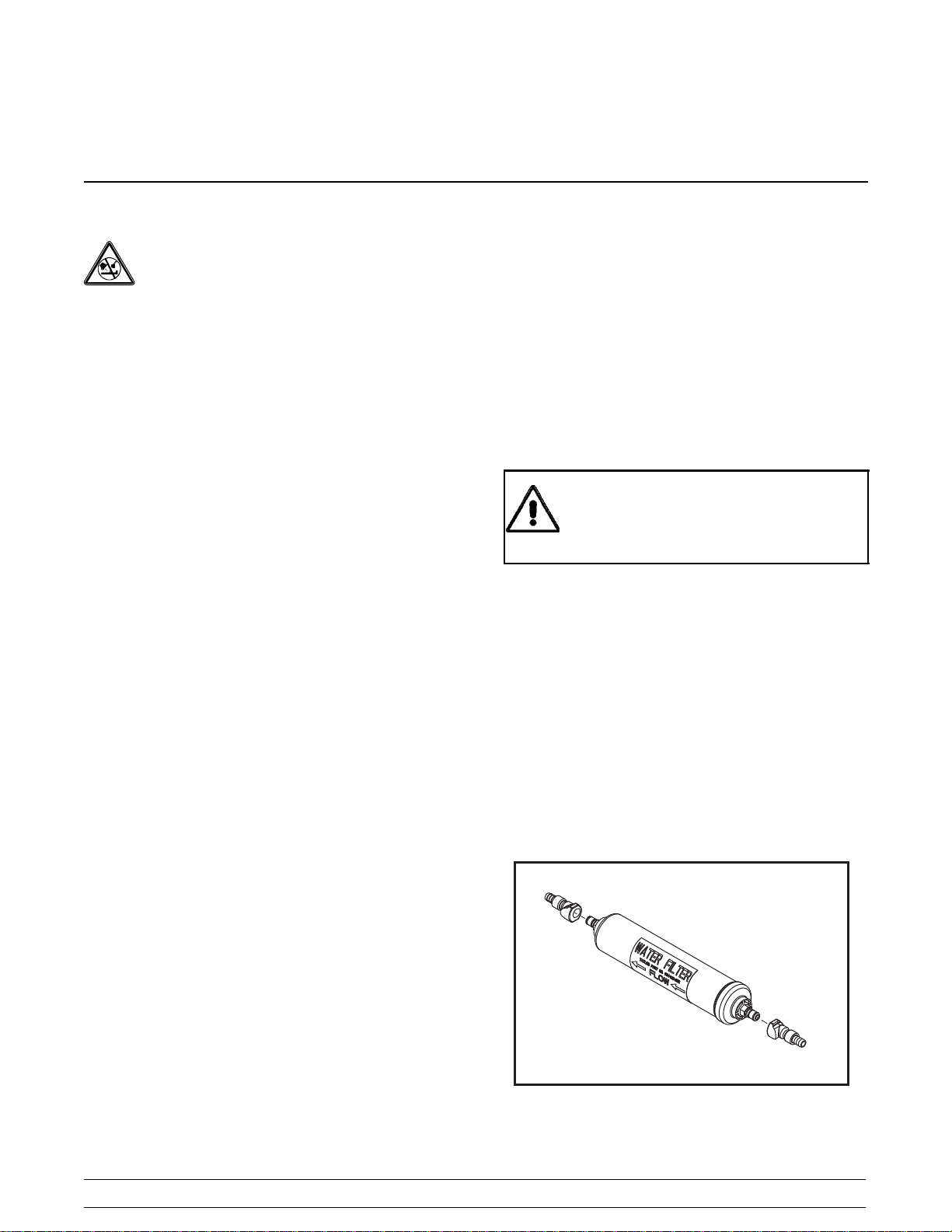
It is always a good practice to have a filter system to
improve the quality of the water and to avoid
clogging the operating components.
IMPORTANT: The water filter (064422--SER) must
be thoroughly flushed with water before connecting it
to the machine. This removes any loose particles
present from the manufacture of the filter that could
clog the flow control. To flush the filter, connect the
inlet end of the filter to the water supply. Position the
outlet end of the filter over an empty pail. Open the
water supply. Allow water to flow through the filter
until the water exiting the filter is clear. Close the
water supply. Attach the outlet end of the filter to the
machine. Reopen the water supply.
DO NOT INSTALL A HAND SHUT-OFF VALVE ON
THE “OUT” LINE! Water cooled units are counter
flow and the water should flow in this order: First
through the automatic water valve. Second, through
the inlet located at the bottom of the condenser.
Third, through the outlet fitting located at the top of
the condenser toanopentrapdrain.
IMPORTANT: Water pressures are pre-set at the
factory. Do not adjust the water pressure.
Improper water adjustments may cause operation
discrepancies.
Model C302 To the Installer
1
Figure 1
071010
Electrical Connections
Each freezer requires one power supply. Check the
data label on the freezer for fuse, circuit ampacity
and electrical specifications. Refer to the wiring
diagram provided inside of the control box, for
proper power connections.
In the United States, this equipment is intended to
be installed in accordance with the National
Electrical Code (NEC), ANSI/NFPA 70-1987. In all
other areas of the world, equipment should be
installed in accordance with the existing local codes.
Please contact your local authorities.
The purpose of the NEC code is the practical
safeguarding of persons and property from hazards
arising from the use of electricity. This code contains
provisions considered necessary for safety.
Compliance therewith and proper maintenance will
result in an installation essentially free from hazard!
The NEC is a United States regulatory agency.
International users must follow local electrical codes.
Stationary appliances which are not equipped with a
power cord and a plug or other device to disconnect
the appliance from the power source must have an
all-pole disconnecting device with a contact gap of at
least 3 mm installed in the external installation.
This equipment is provided with a grounding lug
that is to be properly attached to the rear of the frame
by the authorized installer. The installation location is
marked by the equipotential bonding symbol (5021 of
IEC 60417-1) on the removable panel and the frame.
CAUTION: THIS EQUIPMENT MUST BE
PROPERLY GROUNDED! FAILURE TO DO SO
CAN RESULT IN SEVERE PERSONAL INJURY
FROM ELECTRICAL SHOCK!
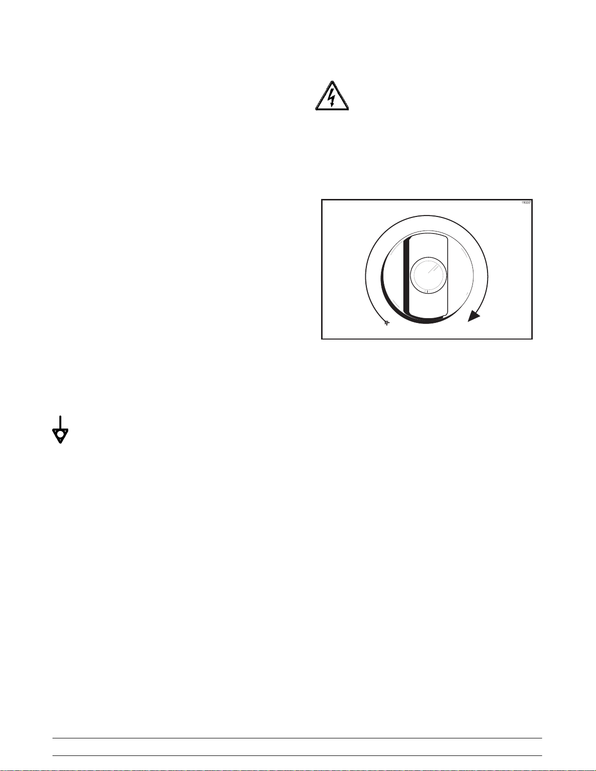
Beater rotation must be clockwise as viewed looking
into the freezing cylinder.
Figure 2
Note: The following procedures should be
performed by a trained service technician.
To correct the rotation on a three-phase unit,
interchange any two incoming power supply lines at
freezer main terminal block only.
To correct rotation on a single-phase unit, change
the leads inside the beater motor. (Follow the
diagram printed on the motor.)
080307
2
Model C302To the Installer

Section 2 To the Operator
The freezer you have purchased has been carefully
engineered and manufactured to give you
dependable operation.
The Model C302, when properly operated and cared
for, will produce a consistent quality product. Like all
mechanical products, this machine will require
cleaning and scheduled maintenance. A minimum
amount of care and attention is necessary if the
operating procedures outlined in this manual are
followed closely.
This Operator's Manual should be read before
operating or performing any maintenance on your
equipment.
Your freezer will NOT eventually compensate and
correct for any errors during the set-up or filling
operations. Thus, the initial assembly and priming
procedures are of extreme importance. It is strongly
recommended that all personnel responsible for the
equipment's operation study these procedures
together in order to be properly trained and to make
sure that no misunderstandings exist.
In the event you should require technical assistance,
please contact your local authorized Taylor
Distributor for service.
If the crossed out wheeled bin symbol is
affixed to this product, it signifies that this product is
compliant with the EU Directive as well as other
similar legislation in effect after August 13, 2005.
Therefore, it must be collected separately after its
use is completed, and cannot be disposed as
unsorted municipal waste.
The user is responsible for returning the product to
the appropriate collection facility, as specified by
your local code.
For additional information regarding applicable local
laws, please contact the municipal facility and/or
local distributor.
Compressor Warranty Disclaimer
The refrigeration compressor(s) on this machine are
warranted for the term indicated on the warranty
card accompanying this machine. However, due to
the Montreal Protocol and the U.S. Clean Air Act
Amendments of 1990, many new refrigerants are
being tested and developed, thus seeking their way
into the service industry. Some of these new
refrigerants are being advertised as drop-in
replacements for numerous applications. It should
be noted that, in the event of ordinary service to this
machine's refrigeration system, only the refrigerant
specified on the affixed data label should be
used. The unauthorized use of alternate refrigerants
will void your compressor warranty. It will be the
owner's responsibility to make this fact known to any
technician he employs.
It should also be noted that Taylor does not warrant
the refrigerant used in its equipment. For example, if
the refrigerant is lost during the course of ordinary
service to this machine, Taylor has no obligation to
either supply or provide its replacement either at
billable or unbillable terms. Taylor does have the
obligation to recommend a suitable replacement if
the original refrigerant is banned, obsoleted, or no
longer available during the five year warranty of the
compressor.
Taylor will continue to monitor the industry and test
new alternates as they are being developed. Should
a new alternate prove, through our testing, that it
would be accepted as a drop-in replacement, then
the above disclaimer would become null and void.
To find out the current status of an alternate
refrigerant as it relates to your compressor warranty,
call the local Taylor Distributor or the Taylor Factory.
Be prepared to provide the Model/Serial Number of
the unit in question.
061211
Model C302 To the Operator
3
Section 3 Safety
We at Taylor are concerned about the safety of the
operator when he or she comes in contact with the
freezer and its parts. Taylor has gone to extreme
efforts to design and manufacture built-in safety
features to protect both you and the service
technician. As an example, warning labels have
been attached to the freezer to further point out
safety precautions to the operator.
IMPORTANT - Failure to adhere to the
following safety precautions may result in
severe personal injury or death. Failure to
comply with these warnings may damage the
machine and its components. Component
damage will result in part replacement expense
and service repair expense.
To Operate Safely:
DO NOT operate the freezer without reading this
operator's manual. Failure to follow this instruction
may result in equipment damage, poor freezer
performance, health hazards, or personal injury.
S DO NOT operate the freezer unless it is
properly grounded.
S DO NOT operate the freezer with larger
fuses than specified on the freezer data
label.
S DO NOT attempt any repairs unless the
main power supply to the freezer has been
disconnected.
Failure to follow these instructions may result in
electrocution. Contact your local authorized Taylor
Distributor for service.
S DO NOT allow untrained personnel to
operate this machine.
S DO NOT operate the freezer unless all
service panels and access doors are
restrained with screws.
S DO NOT remove the freezer door or beater
assembly unless the control switches are in
the “OFF” position.
Failure to follow these instructions may result in
severe personal injury from hazardous moving parts.
CAUTION: This unit is pressurized when
in operation. The control switch must be in the OFF
position until the unit is completely assembled. No
part should ever be removed from the machine while
it is in operation. No parts should be removed until
the control switch has been turned to the OFF
position and all pressure has been relieved by
opening the draw valve. Failure to follow this
instruction may result in severe personal injury from
hazardous moving parts or from the impact of
propelled parts.
S DO NOT put objects or fingers in door
spout. Failure to follow this instruction may
result in contaminated product or personal
injury from blade contact.
S USE EXTREME CAUTION when removing
the beater assembly. The scraper blades
are very sharp and may cause injury.
DO NOT use a water jet to clean or rinse
the freezer. Failure to follow these instructions may
result in serious electrical shock.
061211
This freezer must be placed on a level
surface. Failure to comply may result in personal
injury or equipment damage.
4
Model C302Safety

DO NOT obstruct air intake and discharge openings:
Air cooled units require a minimum of 3” (76 mm) of
air space on both sides, 3” (76 mm) at the rear, and
12” (305 mm) on the top of the unit. Minimum air
clearances must be met to assure adequate air flow
for optimum performance.
This freezer is designed to operate indoors, under
normal ambient temperatures of 70°-75°F
(21°-24°C). The freezer has successfully performed
in high ambient temperatures of 104°F (40°C) at
reduced capacities.
NOISE LEVEL: Airborne noise emission does not
exceed 78 dB(A) when measured at a distance of
1.0 meter from the surface of the machine and at a
height of 1.6 meters from the floor.
050209
Model C302 Safety
5
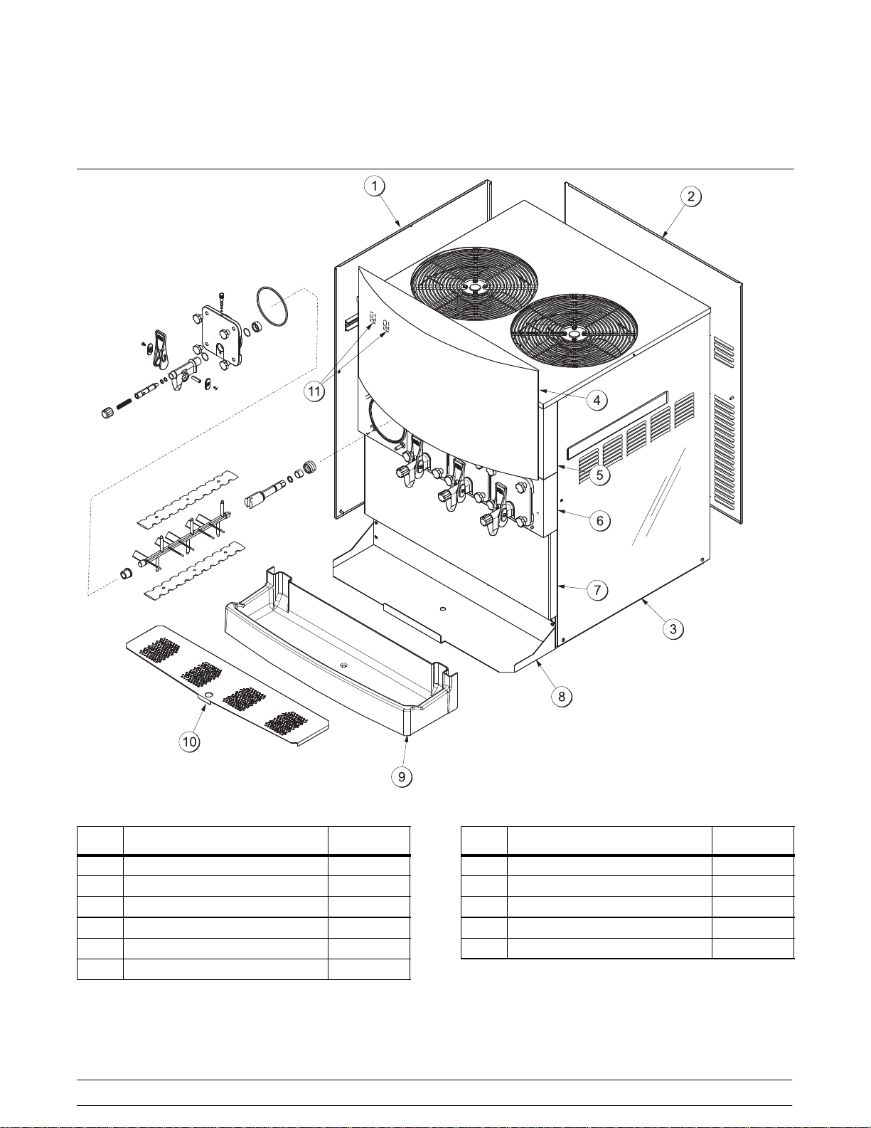
Section 4 Operator Parts Identification
ITEM DESCRIPTION PART NO.
1 PANEL-SIDE*LEFT 059721
2 PANEL-REAR 059657
3 PANEL-SIDE*RIGHT 059722
4 DISPLAY-LIGHTED 059584-27
5 PANEL-FRONT-UPPER 059577
6 PANEL-FRONT-SHELL 059576
Figure 3
6
ITEM DESCRIPTION PART NO.
7 PANEL-FRONT-LOWER 059652
8 SHELF-DRIP TRAY 059653
9 TRAY-DRIP 059654
10 SHIELD-SPLASH 059659
11 SWITCH-ROCKER SPST 059627
Model C302Operator Parts Identification
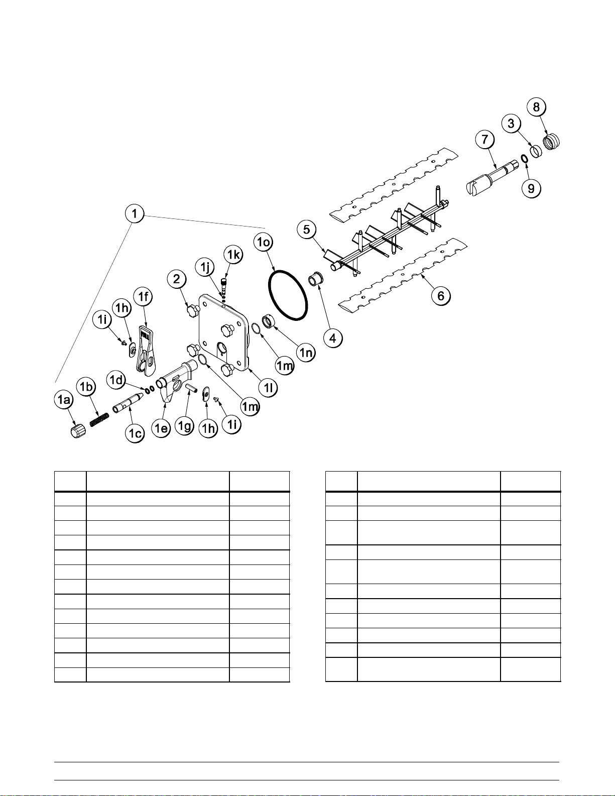
Beater Door Assembly
ITEM DESCRIPTION PART NO.
1 DOOR A.-SLUSH PRESS. X39572-BLA
1a CAP-SPOUT-DOOR-FCB-BLK 046191-BLA
1b SPRING-COMP.480X.072X3.0 039320
1c VALVE-DRAW-DOOR-PRESS. 039324
1d O-RING-9/16 OD X .103W 016369
1e SPOUT-DOOR-FCB-BLACK 046190-BLA
1f HANDLE-DRAW-FCB-BLACK 046192-BLA
1g PIN-PIVOT-SPOUT-DOOR 039321
1h SLIDE-HANDLE-DOOR-BLK 046193-BLA
1i SCREW-10-32X3/8PHL 053869
1j O-RING-9/32 OD X 1/16 WALL 029751
1k PLUG-PRIME-SLUSH-PRESS. 039568
1l DOOR-FREEZER-SLUSH-PRES 039573
Figure 4
ITEM DESCRIPTION PART NO.
1m O-RING-1.129 ODX.989ID 039219
1n NUT-SPOUT-DOOR-PRESS. 039323
1o O-RING-5-1/4ODX.210W
(DOOR)
2 NUT-STUD 043666
3 BUSHING-BEATER
SHAFT/BOOT SEAL
4 BEARING-FRONT-PRESSURE 039349
5 BEATER-PLASTIC-FCB-PRESS. 041182
6 BLADE-SCRAPER-FCB-16INCH 041103
7 SHAFT-BEATER-SLUSH-PRES 039337
8 SEAL-DRIVE SHAFT 032560
9 O-RING-7/8 OD X .139W
(BEATER SHAFT)
017003
042278
025307
100323
Model C302 Operator Parts Identification
7
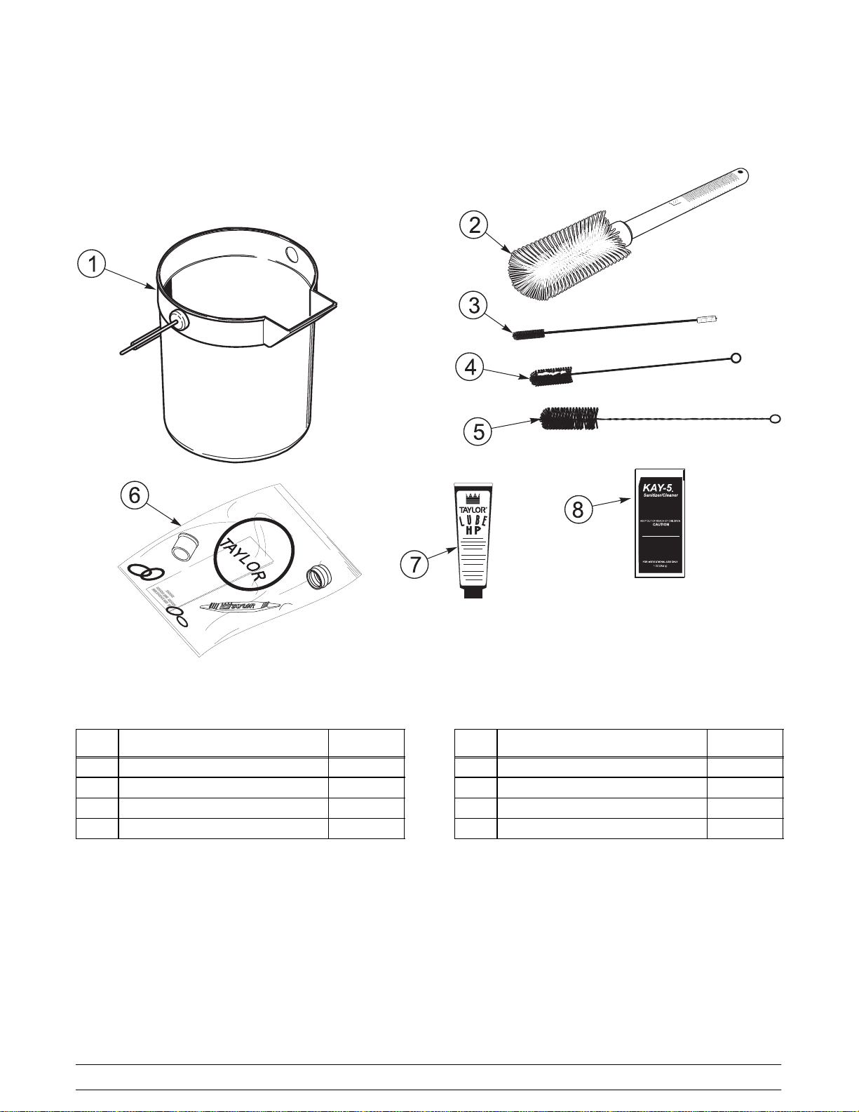
Accessories
ITEM DESCRIPTION PART NO.
1 PAIL-MIX 10 QT 013163
2 BRUSH-MIXPUMP BODY-3”X7” 023316
3 BRUSH-DOUBLE ENDED 013072
4 BRUSH-REAR BRG 1”DX2“L 013071
Figure 5
8
ITEM DESCRIPTION PART NO.
5 BRUSH-DRAW VALVE 1-1/2”OD 014753
6 KIT A.-TUNE UP X59121
7 LUBRICANT-TAYLORHI PERF 048232
8 SANITIZERKAY-5 125 PACKETS 041082
Model C302Operator Parts Identification
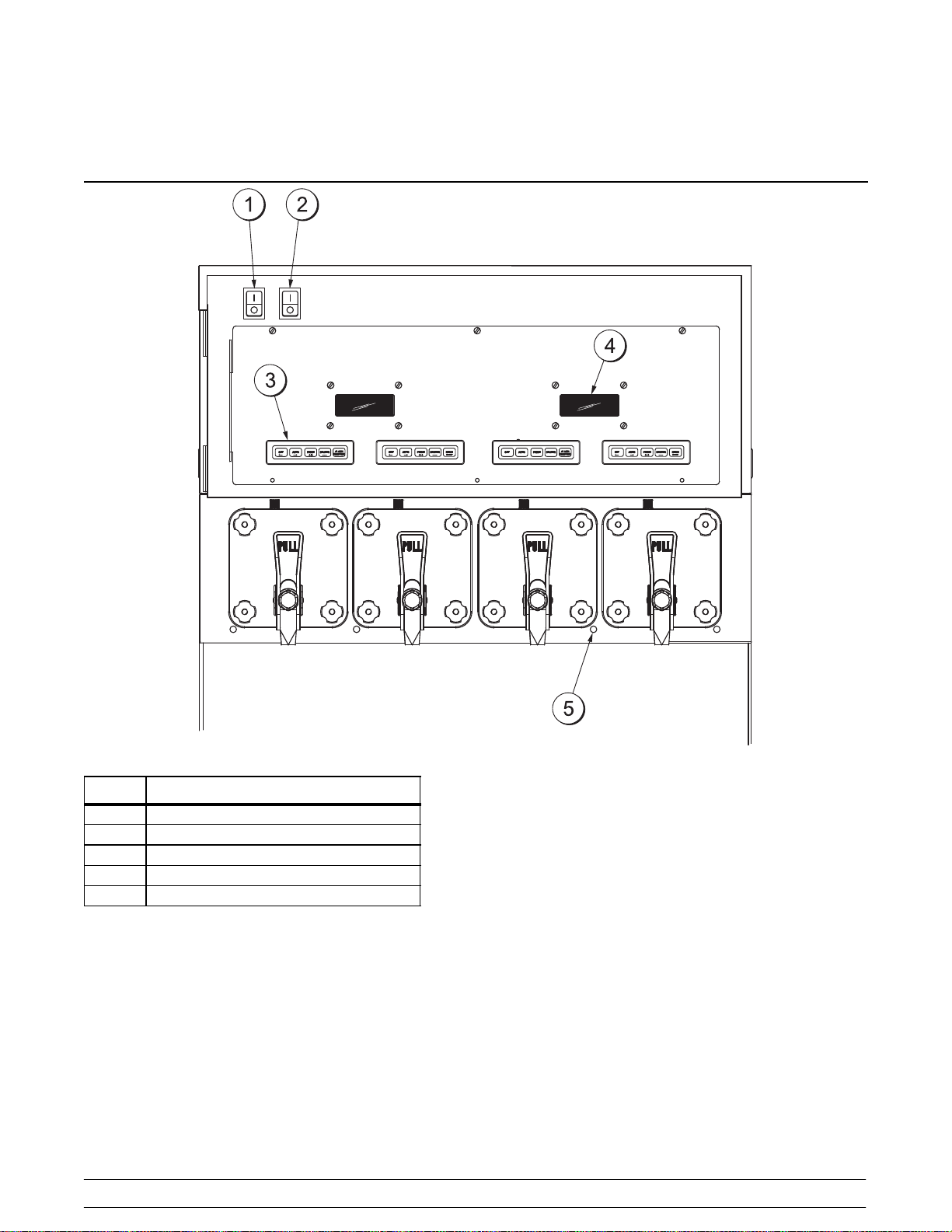
Section 5 Important: To the Operator
Figure 6
ITEM DESCRIPTION
1 CONTROL SWITCH-LEFT SIDE
2 CONTROL SWITCH-RIGHT SIDE
3 KEYPAD
4 LIQUID CRYSTAL DISPLAY
5 PRODUCT LIGHT
Model C302 Important: To the Operator
Control Switches
There are two control switches located at the top left
corner of the upper front panel, behind the
illuminated display. The left switch controls the two
freezing cylinders on the left side of the unit. The
right switch controls the two freezing cylinders on
the right side of the unit. When placed in the ON
position, these control switches allow SLUSHTECH
operation.
9

Liquid Crystal Displays
Pressing the A UTO (- -> ) keys for each freezing
cylinder will display this screen.
There are two Liquid Crystal Displays (LCD's)
located on the upper front panel behind the
illuminated display. The two LCD's display
information for the two freezing cylinders located
directly beneath them. These pairs of freezing
cylinders are each labeled “left” and “right” per LCD.
The LCD's show the current operating mode of the
freezing cylinders. They also indicate whether there
is enough syrup, CO2, and water being supplied to
the freezer. If an error in the machine operation
occurs, a warning tone will sound and the word
“FAULT” will flash on the third line of the display.
Operational Mode Displays
The screens below illustrate the operational mode
information displayed during normal operation. The
two LCD's display information corresponding to the
two freezing cylinders located directly beneath them.
These pairs of freezing cylinders are each labeled
“left” and “right” per LCD.
AUTO MODE AUTO
OK SYRUP OK
CO2-OK WATER-OK
Line 1 indicates the operating mode for each
freezing cylinder.
Line 2 indicates the status of the syrup systems in
each freezing cylinder. As long as syrup is available,
the word “OK” will appear on the LCD. When the
syrup supply is insufficient, the word “OUT” will flash
on the LCD. The same rules apply to the fourth line
which indicates the status of the CO
and the H2O.
2
The third line of this display is a fault indicator. If an
error in machine operation occurs, the word “FAULT
will be displayed on the LCD.
BEATER MODE BEATER
OUT SYRUP OUT
- -FAULT- - - -FAULT- CO2-OUT H2O-OUT
When the unit is plugged into the wall receptacle
and the control switch is in the ON position, this
screen appears.
SAFETY TIMEOUT
ANY KEY ABORT
This display will remain on the LCD for 60 seconds
unless a key is pressed. If any key is pressed (or 60
seconds passes) then the next screen appears.
OFF MODE OFF
OK SYRUP OK
CO2-OK WATER-OK
Note: Syrup, CO2and water are satisfied.
Note: Repeat all information and programming
procedures for each individual control from the left to
the right.
Operator Menu Display
The OPERATOR MENU is used to enter into the
operating screens. To access the OPERATOR
MENU, simply press the MENU (SEL) key. The
cursor will flash under the letter “A”, indicating that
this is screen A. To select a different screen, use the
AUTO (- ->) and OFF (<- -) keys t o move the cursor
to the desired screen selection and press the MENU
(SEL) key.
OPERATOR MENU
B C D E F G H I
A
EXIT MENU
<- - - -> SEL
10
Model C302Important: To the Operator
Operator Menu Timeout
If the display is left in the operator menu or any of
the operator menu selections, except for Current
Conditions, the display will return to the system
mode screen 60 seconds after the last keypress.
The Current Conditions screen will be displayed until
manually changed.
Finding Current Fault Conditions
Screen B is FAULT DESCRIPTION. The fault
description will indicate if there is a fault in one of the
freezing cylinders. When the actual fault is
corrected, the warning tone will stop. Only “BRL
NOT COO LING” requires pr es s ing the OFF (<- -)
key to clear the fault message and the warning tone.
Fault Messages
Beater Overload Beater is out on overload.
2. BEATER OVERLOAD - Beater motor is out on
overload. When this fault occurs, the affected
side of the machine automatically turns off. The
fault clears when the condition is corrected.
FAULT DESCRIPTION
L: BEATER OVERLOAD
R: BEATER OVERLOAD
CLR + + + SEL
3. CHK REFRIG SYS PSI - Compressor is out on
high head pressure. When this fault occurs, the
machine automatically turns off. The fault
clears when the condition is corrected.
Chk Refrig Sys Psi Out on compressor high
pressure cut-out.
Thermistor Short Shorted thermistor probe.
Thermistor Open Open thermistor probe.
H2O Pressure Low Water pressure is low.
CO2 Pressure Low CO2pressure is low.
Syrup Pressure Low Syrup is no longer present.
BRLTemp2High Freezing cylinder
temperature is above 120_F
(49_C).
BRL Not Cooling Freezing cylinder is not
cooling after 5 minutes.
No Fault Found No fault conditions are
apparent.
The following are explanations of the possible faults
and the display screens. Lines 2 and 3 indicate the
faults found in freezing cylinders 1 and 2
respectively.
1. NO FAULT FOUND - No fault conditions are
apparent.
FAULT DESCRIPTION
L: CHK REFRIG SYS PSI
R: CHK REFRIG SYS PSI
CLR + + + SEL
4. THERMISTOR SHORT - One or both of the
barrel (freezing cylinder) thermistor probes are
faulty.
FAULT DESCRIPTION
L: THERMISTOR SHORT
R: NO FAULT FOUND
CLR + + + SEL
5. THERMISTOR OPEN - One or both of the
barrel (freezing cylinder) thermistor probes are
faulty.
FAULT DESCRIPTION
L: NO FAULT FOUND
R: NO FAULT F OUND
CLR + + + SEL
Model C302 Important: To the Operator
11
FAULT DESCRIPTION
L: THERMISTOR OPEN
R: NO FAULT FOUND
CLR + + + SEL
060823
6. SYRUP PRESS LOW - When the syrup out
indicator displays a lack of syrup, the barrel will
enter a HOLD mode. At this time, no
refrigeration or product flow from the flow
control will be allowed. Only the beater will
operate. When the syrup is satisfied the barrel
will refill the product tank and then
automatically return to the AUTO mode. The
fault message and the warning tone will clear.
(See “Syrup Out Indicator ” on page 15.)
FAULT DESCRIPTION
L: NO FAULT FOUND
R: SYRUP PRESS LOW
CLR + + + SEL
7. CO2PRESSURE LOW - When the CO2out
indicator displays a lack of CO
internal timer will start. If the CO
, a 60 second
2
is not
2
replenished at the end of the 60 seconds, both
freezing cylinders will shut down and this fault
message will appear. Replenish the CO
2
and
the fault message and warning tone will clear.
9. BRL NOT COOLING - A freezing cylinder
check has been established for the AUTO
mode of operation. If a freezing cylinder enters
the AUTO mode, the control will check product
temperature. After five minutes, it will again
check product temperature. If product
temperature does not drop in that five minute
time span, the freezing cylinder will shut down
and this message will appear on the fault
screen. For this check to be valid, the product
temperature must be above 40_F(4.4_C).
FAULT DESCRIPTION
L: BARREL NOT COOLING
R: NO FAULT FOUND
CLR + + + SEL
10. BRL TEMP 2 HIGH - A maximum allowable
product temperature has been established to
prevent product from excessive heating. If the
product exceeds 120_F(49_C) temperature for
any reason (in any mode of operation), the
entire unit shuts down.
FAULT DESCRIPTION
L: CO2 PRESSURE LOW
R: CO2 PRESSURE LOW
CLR + + + SEL
8. H2O PRESSURE LOW - When the water out
indicator displays a lack of water, a 60 second
internal timer will start. If the water is not
replenished at the end of the 60 seconds, all
freezing cylinders will shut down and this fault
message will appear. Replenish the water and
the fault message and warning tone will clear.
FAULT DESCRIPTION
L: H2O PRESSURE LOW
R: H2O PRESSURE LOW
CLR + + + SEL
FAULT DESCRIPTION
L: BARREL TEMP 2 HIGH
R: NO FAULT FOUND
CLR + + + SEL
Faults, when corrected, are cleared from the fault
description screen, with the following exception: BRL
NOT COOLING. This fault requires the operator to
press the O FF (<- - ) key (when in the FAULT
DESCRIPTION screen) in order for the fault to
discontinue.
To see if there is more than one fault in either
freezing cylinder, press the P RIME (+ + +) key. To
return to the OPERATOR MENU, press the MENU
(SEL) key once. To return to the Main Screen, use
the AUTO (- ->) key to cycle to MENU ITEM A, t hen
press the MENU (SEL) key.
12
Model C302Important: To the Operator
Screen C is SET CLOCK. Use the AUTO (- ->) and
OFF (<- -) keys to place the curs or under the
element to be set (hours, minutes, month, day, or
year). Use the PRIME (+++) and BEAT ER (- - -)
keys to increment or decrement the value. Press the
MENU (SEL) key to advance to the Daylight Saving
Time screen.
Note: The clock is programmed with military time.
SET CLOCK
:30 2/25/04
14
<- - - -> + + + - - - SEL
Repeat the procedure for the right freezing cylinder
under each LCD.
MANUAL DEFROST
RIGHT SIDE YES
<- - - -> SEL
NO
Note: Only one freezing cylinder per LCD may be
placed in the DEFROST mode at a given time.
Attempting to place more than one freezing cylinder
into DEFROST will result in the following screen:
This screen will appear if an invalid date is entered.
(example: If the date entered exceeds the days of
that month.)
SET CLOCK
:30 02/31/04
14
INVALID DATE
SEL
This screen allows the Daylight Saving Time
options. If the Daylight Saving Time option is
enabled, then the time will be advanced by one hour
at 2:00 a.m. on the first Sunday in April, and will be
retarded by one hour at 2:00 a.m. on the last
Sunday in October.
DAYLIGHT SAVING TIME
ENABLE
<- - - -> SEL
DISABLE
Screen D is MANUAL DEFROST. This screen
allows the operator to manually defrost the left
freezing cylinders under each LCD.
ALREADY IN DEFROST
Press the MENU (SEL) key to return the unit to the
OPERATOR MENU.
Screen E is SYSTEM INFORMATION.Itconsists
of 6 display features.
The first feature indicates the software version.
SYSTEM INFORMATION
C300 CONTROL UVC2
VERSION 1.00
SEL
The second feature indicates the bill of material
number and the serial number.
It also indicates if the unit is equipped with a water
pressure switch.
B.O.M. C30227C000
S/N K0000000
WITH H20 PRESS SW
SEL
Place the cursor under YES, press the MENU (SEL)
key, and the command will be executed.
MANUAL DEFROST
LEFT SIDE YES
<- - - -> SEL
NO
Model C302 Important: To the Operator
The third feature indicates the version number of the
language and text.
SYSTEM INFORMATION
LANGUAGE
VERSION 1.09 ENGLISH 446
SEL
13
 Loading...