


Slush Freezer
Model C300
Original Operating Instructions
055072-M
9/26/08 (Original Publicaton)
(Updated 10/11/11)

Complete this page for quick reference when service is required:
Taylor Distributor:
Address:
Phone:
Fax:
E--mail:
Service:
Parts:
Date of Installation:
Information found on the data label:
Model Number:
Serial Number:
Electrical Specs: Voltage Cycle
Phase
Maximum Fuse Size: A
Minimum Wire Ampacity: A
E September, 2008 Taylor
All rights reserved.
055072--M
The word Taylor and the Crown design
are registered trademarks in the United States
of America and certain other countries.
Taylor Company
750 N. Blackhawk Blvd.
Rockton, IL 61072

Table of Contents
Section 1 To the Installer 1............................................
Section 2 To the Operator 5...........................................
Section 3 Safety 6....................................................
Section 4 Operator Parts Identification 8...............................
Beater Door Assembly 9.................................................
Accessories 10..........................................................
Section 5 Important: To the Operator 11.................................
Control Switch 11........................................................
Liquid Crystal Display 11..................................................
Operational Mode Display 11..............................................
Operator Menu Display 12................................................
Syrup Out Indicator 17....................................................
CO2 Out Indicator 17.....................................................
Water Out Indicator 17....................................................
Audio Alarm Silencer 17..................................................
Product Light 17.........................................................
Sampling Valve 17.......................................................
Daily Procedures 17......................................................
Section 6 Operating Procedures 18.....................................
Assembly 18............................................................
Sanitizing 23............................................................
Priming/Brixing 25........................................................
120 Day Closing Procedure 27............................................
Draining Product From the Freezing Cylinder 28.............................
Table of Contents Model C300

Table of Contents -- Page 2
Rinsing 28..............................................................
Cleaning 29.............................................................
Disassembly 29..........................................................
Brush Cleaning 30.......................................................
Section 7 Important: Operator Checklist 31..............................
During Cleaning and Sanitizing 31.........................................
Troubleshooting Bacterial Count 31........................................
Regular Maintenance Checks 31...........................................
Winter Storage 32........................................................
Section 8 Troubleshooting Guide 33....................................
Section 9 Parts Replacement Schedule 35...............................
Section 10 Parts List 36.................................................
Wiring Diagrams 47......................................................
Note: Continuing research results in steady improvements; therefore, information
in this manual is subject to change without notice.
Note: Only instructions originating from the factory or its authorized translation
representative(s) are considered to be the original set of instructions.
E September, 2008 Taylor (Original Publication)
(Updated October, 2011)
All rights reserved.
055072--M
The word Taylor and the Crown design
are registered trademarks in the United States
of America and certain other countries.
Table of Contents Model C300
Taylor Company
750 N. Blackhawk Blvd.
Rockton, IL 61072
Section 1 To the Installer
The following are general installation instructions. For
complete installation details, please see the check out
card.
cause severe injuries.
This unit has many sharp edges that can
Installer Safety
In all areas of the world, equipment should be
installed in accordance with existing local codes.
Please contact your local authorities if you have any
questions.
Care should be taken to ensure that all basic safety
practices are followed during the installation and
servicing activities related to the installation and
service of Taylor equipment.
S Only authorized Taylor service personnel
should perform installation and repairs on
the equipment.
S Authorized service personnel should consult
OSHA Standard 29CFRI910.147 or the
applicable code of the local area for the
industry standards on lockout/tagout
procedures before beginning any installation
or repairs.
S Authorized service personnel must ensure
that the proper PPE is available and worn
when required during installation and
service.
S Authorized service personnel must remove
all metal jewelry, rings, and watches before
working on electrical equipment.
The main power supply(s) to the freezer must
be disconnected prior to performing any repairs.
Failure to follow this instruction may result in personal
injury or death from electrical shock or hazardous
moving parts as well as poor performance or damage
to the equipment.
Note:Allrepairsmustbeperformedbyan
authorized Taylor Service Technician.
Site Preparation
Review the area where the unit will be installed
before uncrating the unit. Make sure that all possible
hazards to the user and the equipment have been
addressed.
Air Cooled Units
Air cooled units require a minimum of 3” (76 mm) of
air space on one side, 3” (76 mm) at the rear, and
12” (305 mm) on the top of the unit. This is required
to allow for adequate air flow through the
condenser(s). Failure to allow adequate clearance
can reduce the refrigeration capacity of the freezer
and possibly cause permanent damage to the
compressor(s).
For Indoor Use Only: This unit is designed to operate
indoors, under normal ambient temperatures of
70_-75_F(21_-24_C). The freezer has successfully
performed in high ambient temperatures of
104_(40_C) at reduced capacities.
This unit must NOT be installed in an area
where a water jet or hose can be used. NEVER use a
water jet or hose to rinse or clean the unit. Failure to
follow this instruction may result in electrocution.
This unit must be installed on a level surface
to avoid the hazard of tipping. Extreme care should be
taken in moving this equipment for any reason. Two or
more persons are required to safely move this unit.
Failure to comply may result in personal injury or
equipment damage.
Uncrate the unit and inspect it for damage. Report any
damage to your Taylor Distributor.
This piece of equipment is made in the USA and has
USA sizes of hardware. All metric conversions are
approximate and vary in size.
081208
Model C300 To the Installer
1
Water Cooled Refrigeration Units
(Water Cooled Units Only)
On the back of the unit, two additional 3/8” (9.5 mm)
F.P.T. water connections for condenser inlet and
outlet have been provided for easy hook--up. 3/8”
(9.5 mm) inside diameter water lines should be
connected to the machine. Flexible lines are
recommended if local codes permit. Failure to use
adequate size water lines may cause the unit to go
on high head pressure and shut down.
Depending on local water conditions, it may be
advisable to install a water strainer to prevent
foreign substances from clogging the automatic
water valve.
DO NOT INSTALL A HAND SHUT--OFF VALVE ON
THE “OUT” LINE! Water cooled units are counter
flow and the water should flow in this order: First
through the automatic water valve. Second, through
the inlet located at the bottom of the condenser.
Third, through the outlet fitting located at the top of
the condenser toanopentrapdrain.
IMPORTANT: Water pressures are pre--set at the
factory. Do not adjust the water pressure.
Improper water adjustments may cause operation
discrepancies.
A back flow prevention device is required
on the incoming water connection side. Please
refer to the applicable National, State, and local codes
for determining the proper configuration.
Water Connections
An adequate cold water supply must be provided
with a hand shut--off valve. On the back of the unit, a
3/8” (9.5 mm) M.F.L. water connection has been
provided for easy hook--up. A flexible line is
recommended, if local codes permit. A minimum of
25 psi water pressure is required to avoid having the
unit cut out the low water pressure switch. A booster
pump must be provided if this pressure is not
available.
Note: Water lines beyond 200 ft. (61 m) require 1/2”
(13 mm) water lines.
INSTALL POTABLE WATER CONNECTION
WITH ADEQUATE BACK-FLOW
PROTECTION TO COMPLY WITH
APPLICABLE NATIONAL, STATE AND
LOCAL CODES.
It is always a good practice to have a filter system to
improve the quality of the water and to avoid
clogging the operating components.
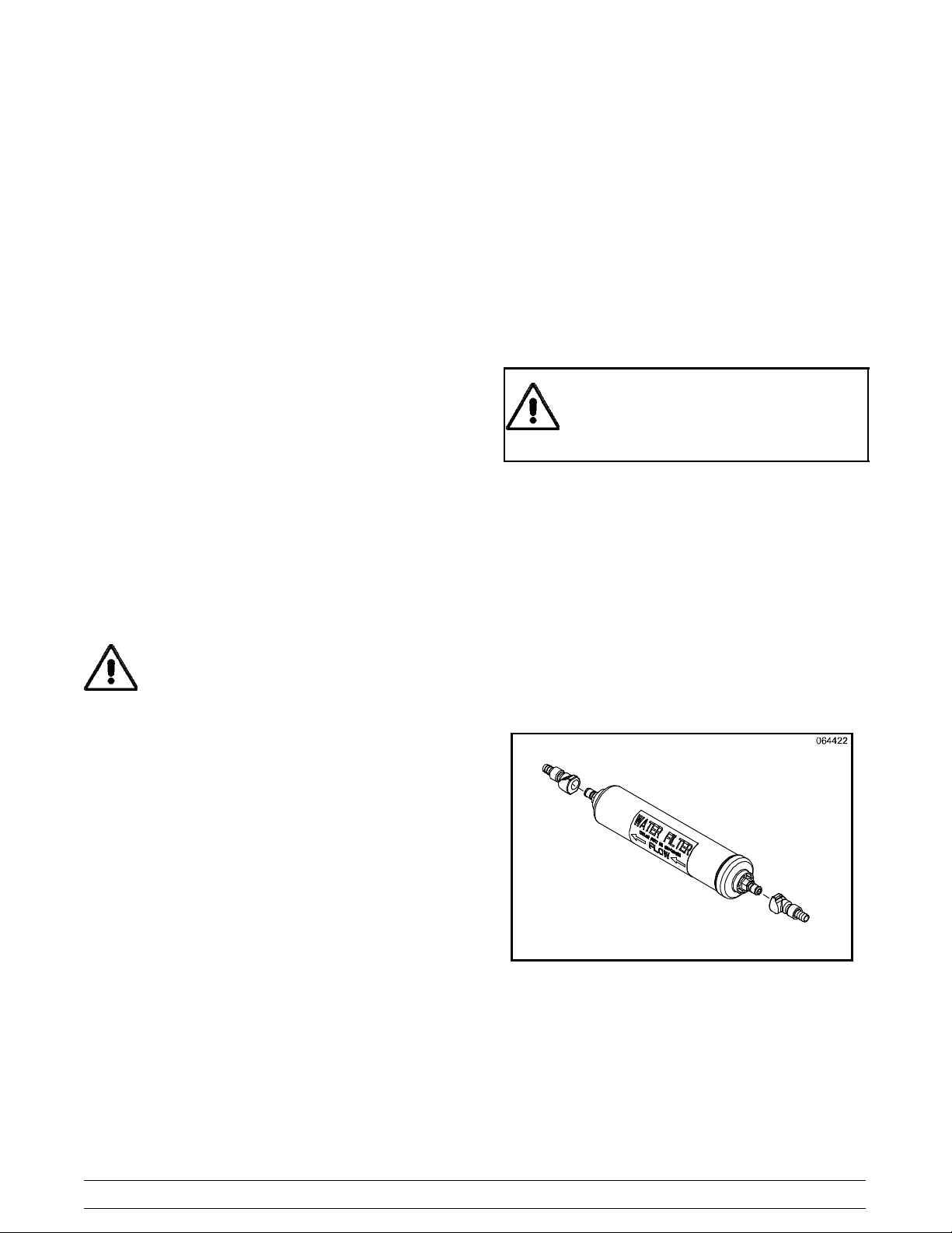
IMPORTANT: The water filter (064422--SER) must
be thoroughly flushed with water before connecting it
to the machine. This removes any loose particles
present from the manufacture of the filter that could
clog the flow control. To flush the filter, connect the
inlet end of the filter to the water supply. Position the
outlet end of the filter over an empty pail. Open the
water supply. Allow water to flow through the filter
until the water exiting the filter is clear. Close the
water supply. Attach the outlet end of the filter to the
machine. Reopen the water supply.
Figure 1
2
Model C300To the Installer
Electrical Connections
In the United States, this equipment is intended to
be installed in accordance with the National
Electrical Code (NEC), ANSI/NFPA 70--1987. The
purpose of the NEC code is the practical
safeguarding of persons and property from hazards
arising from the use of electricity. This code contains
provisions considered necessary for safety.
Compliance therewith and proper maintenance will
result in an installation essentially free from hazard!
In all other areas of the world, equipment should be
installed in accordance with the existing local codes.
Please contact your local authorities.
FOLLOW YOUR LOCAL ELECTRICAL CODES!
Each unit requires one power supply for each data
label on the unit. Check the data label(s) on the
freezer for branch circuit overcurrent protection or
fuse, circuit ampacity, and other electrical
specifications. Refer to the wiring diagram provided
inside of the control box for proper power
connections.
CAUTION: THIS EQUIPMENT MUST BE
PROPERLY GROUNDED! FAILURE TO DO SO
CAN RESULT IN SEVERE PERSONAL INJURY
FROM ELECTRICAL SHOCK!
Stationary appliances which are not equipped
with a power cord and a plug or another device to
disconnect the appliance from the power source must
have an all-pole disconnecting device with a contact
gap of at least 3 mm installed in the external
installation.
Appliances that are permanently connected to
fixed wiring and for which leakage currents may
exceed 10 mA, particularly when disconnected or not
used for long periods, or during initial installation, shall
have protective devices such as a GFI, to protect
against the leakage of current, installed by the
authorized personnel to the local codes.
Supply cords used with this unit shall be
oil-resistant, sheathed flexible cable not lighter than
ordinary polychloroprene or other equivalent synthetic
elastomer-sheathed cord (Code designation 60245
IEC 57) installed with the proper cord anchorage to
relieve conductors from strain, including twisting, at
the terminals and protect the insulation of the
conductors from abrasion.
Beater Rotation
DO NOT operate this freezer with larger fuses
than specified on the unit data label. Failure to follow
this instruction may result in electrocution or damage
to the machine.
This unit is provided with an equipotential
grounding lug that is to be properly attached to the rear
of the frame by the authorized installer. The installation
location is marked by the equipotential bonding
symbol (5021 of IEC 60417-1) on both the removable
panel and the equipments frame.
Model C300 To the Installer
looking into the freezing cylinder.
Note: The following procedures should be
performed by a trained service technician.
To correct the rotation on a three--phase unit,
interchange any two incoming power supply lines at
freezer main terminal block only.
To correct rotation on a single--phase unit, change
the leads inside the beater motor. (Follow the
diagram printed on the motor.)
3
Beater rotation must be clockwise as viewed
110506
Initial Freezing Cylinder Cleaning
Due to the types of products used in FCB
equipment, it is imperative that the freezing cylinder
and the inlet tube be thoroughly brush cleaned,
rinsed, and sanitized before running any product.
Prepare a cleaning solution, using 2 oz. of liquid
detergent in 2 gallons of warm water. Using this
solution, brush clean the freezing cylinder and the
inlet tube. Rinse the freezing cylinder and the inlet
tube with clean water and then sanitize, using the
sanitizing procedures outlined in this Operator
Manual, starting on page 23.
Refrigerant
In consideration of our environment, Taylor
proudly uses only earth friendly HFC refrigerants. The
HFC refrigerant used in this unit is R404A. This
refrigerant is generally considered non-toxic and
non-flammable, with an Ozone Depleting Potential
(ODP) of zero (0).
However, any gas under pressure is potentially
hazardous and must be handled with caution.
NEVER fill any refrigerant cylinder completely with
liquid. Filling the cylinder to approximately 80% will
allow for normal expansion.
Refrigerant liquid sprayed onto the skin may
cause serious damage to tissue. Keep eyes and skin
protected. If refrigerant burns should occur, flush
immediately with cold water. If burns are severe, apply
ice packs and contact a physician immediately.
Taylor reminds technicians to be cautious of
government laws regarding refrigerant recovery,
recycling, and reclaiming systems. If you have any
questions regarding these laws, please contact the
factory Service Department.
WARNING: R404A refrigerant used in
conjunction with polyolester oils is extremely moisture
absorbent. When opening a refrigeration system, the
maximum time the system is open must not exceed 15
minutes. Cap all open tubing to prevent humid air or
water from being absorbed by the oil.
090219
4
Model C300To the Installer

Section 2 To the Operator
The freezer you have purchased has been carefully
engineered and manufactured to give you
dependable operation.
The Model C300, when properly operated and cared
for, will produce a consistent quality product. Like all
mechanical products, this machine will require
cleaning and scheduled maintenance. A minimum
amount of care and attention is necessary if the
operating procedures outlined in this manual are
followed closely.
This Operator’s Manual should be read before
operating or performing any maintenance on your
equipment.
Your freezer will NOT eventually compensate and
correct for any errors during the set--up or filling
operations. Thus, the initial assembly and priming
procedures are of extreme importance. It is strongly
recommended that all personnel responsible for the
equipment’s operation study these procedures
together in order to be properly trained and to make
sure that no misunderstandings exist.
In the event you should require technical assistance,
please contact your local authorized Taylor
Distributor for service.
Note: Warranty is valid only if the parts are
authorized Taylor parts, purchased from an
authorized Taylor Distributor, and the required
service work is provided by an authorized Taylor
service technician. Taylor reserves the right to deny
warranty claims on equipment or parts if
non--approved parts or refrigerant were installed in
the machine, system modifications were performed
beyond factory recommendations, or it is determined
that the failure was caused by neglect or abuse.
Note: Constant research results in steady
improvements; therefore, information in this
manual is subject to change without notice.
If the crossed out wheeled bin symbol is
affixed to this product, it signifies that this product is
compliant with the EU Directive as well as other
similar legislation in effect after August 13, 2005.
Therefore, it must be collected separately after its
use is completed, and cannot be disposed as
unsorted municipal waste.
The user is responsible for returning the product to
the appropriate collection facility, as specified by
your local code.
For additional information regarding applicable local
laws, please contact the municipal facility and/or
local distributor.
Compressor Warranty Disclaimer
The refrigeration compressor(s) on this machine are
warranted for the term indicated on the warranty
card accompanying this machine. However, due to
the Montreal Protocol and the U.S. Clean Air Act
Amendments of 1990, many new refrigerants are
being tested and developed, thus seeking their way
into the service industry. Some of these new
refrigerants are being advertised as drop--in
replacements for numerous applications. It should
be noted that, in the event of ordinary service to this
machine’s refrigeration system, only the refrigerant
specified on the affixed data label should be
used. The unauthorized use of alternate refrigerants
will void your compressor warranty. It will be the
owner’s responsibility to make this fact known to any
technician he employs.
It should also be noted that Taylor does not warrant
the refrigerant used in its equipment. For example, if
the refrigerant is lost during the course of ordinary
service to this machine, Taylor has no obligation to
either supply or provide its replacement either at
billable or unbillable terms. Taylor does have the
obligation to recommend a suitable replacement if
the original refrigerant is banned, obsoleted, or no
longer available during the five year warranty of the
compressor.
Taylor will continue to monitor the industry and test
new alternates as they are being developed. Should
a new alternate prove, through our testing, that it
would be accepted as a drop--in replacement, then
the above disclaimer would become null and void. To
find out the current status of an alternate refrigerant
as it relates to your compressor warranty, call the
local Taylor Distributor or the Taylor Factory. Be
prepared to provide the Model/Serial Number of the
unit in question.
Model C300 To the Operator
5
Section 3 Safety
We at Taylor are concerned about the safety of the
operator when he or she comes in contact with the
freezer and its parts. Taylor has gone to extreme
efforts to design and manufacture built--in safety
features to protect both you and the service
technician. As an example, warning labels have
been attached to the freezer to further point out
safety precautions to the operator.
IMPORTANT -- Failure to adhere to the
following safety precautions may result in
severe personal injury or death. Failure to
comply with these warnings may damage the
machine and its components. Component
damage will result in part replacement expense
and service repair expense.
DO NOT operate the freezer without reading
this Operator Manual. Failure to follow this instruction
may result in equipment damage, poor freezer
performance, health hazards, or personal injury.
Per IEC 60335--1 and its part 2 standards, “This
appliance is to be used only by trained personnel. It
is not intended for use by children or people with
reduced physical, sensory, or mental capabilities, or
lack of experience and knowledge, unless given
supervision or instruction concerning the use of the
appliance by a person responsible for their safety.”
This unit is provided with an equipotential
grounding lug that is to be properly attached to the rear
of the frame by the authorized installer. The installation
location is marked by the equipotential bonding
symbol (5021 of IEC 60417-1) on both the removable
panel and the equipments frame.
DO NOT use a water jet to clean or rinse the
freezer. Failure to follow these instructions may result
in serious electrical shock.
S DO NOT operate the freezer unless it is
properly grounded.
S DO NOT operate the freezer with larger
fuses than specified on the freezer data
label.
S All repairs must be performed by an
authorized Taylor service technician. The
main power supplies to the machine must
be disconnected prior to performing any
repairs.
S Cord Connected Units: Only Taylor
authorized service technicians may install a
plug on this unit.
S Stationary appliances which are not
equipped with a power cord and a plug or
another device to disconnect the appliance
from the power source must have an all-pole
disconnecting device with a contact gap of
at least 3 mm installed in the external
installation.
S Appliances that are permanently connected
to fixed wiring and for which leakage
currents may exceed 10 mA, particularly
when disconnected or not used for long
periods, or during initial installation, shall
have protective devices such as a GFI, to
protect against the leakage of current,
installed by the authorized personnel to the
local codes.
S Supply cords used with this unit shall be
oil-resistant, sheathed flexible cable not
lighter than ordinary polychloroprene or
other equivalent synthetic
elastomer-sheathed cord (Code designation
60245 IEC 57) installed with the proper cord
anchorage to relieve conductors from strain,
including twisting, at the terminals and
protect the insulation of the conductors from
abrasion.
Failure to follow these instructions may result in
electrocution. Contact your local authorized Taylor
Distributor for service.
110506
6
Model C300Safety
S DO NOT allow untrained personnel to
operate this machine.
S DO NOT operate the freezer unless all
service panels and access doors are
restrained with screws.
S DO NOT remove any internal operating
parts (example: freezer door, beater,
scraper blades, etc.) unless all control
switches are in the OFF position.
Failure to follow these instructions may result in
contaminated product or severe personal injury to
fingers or hands from hazardous moving parts.
This unit has many sharp edges that can
cause severe injuries.
S DO NOT put objects or fingers in the door
spout. This may contaminate the product
and cause severe personal injury from blade
contact.
S USE EXTREME CAUTION when removing
the beater asssembly. The scraper blades
are very sharp.
CAUTION: This unit is pressurized when
in operation. The control switch must be in the OFF
position until the unit is completely assembled. No
part should ever be removed from the machine while
it is in operation. No part should be removed until
the control switch has been turned to the OFF
position and all pressure has been relieved by
opening the draw valve.
Failure to follow these instructions may result in
severe personal injury from hazardous moving parts
or from the impact of propelled parts.
DO NOT obstruct air intake and discharge openings:
Air cooled units require a minimum of 3” (76 mm) of
air space on one side, 3” (76 mm) at the rear, and
12” (305 mm) on the top of the unit. This is required
to allow for adequate air flow through the condenser(s). Failure to follow this instruction may
cause poor freezer performance and damage to the
machine.
For Indoor Use Only: This unit is designed to operate
indoors, under normal ambient temperatures of
70_-75_F(21_-24_C). The freezer has successfully
performed in high ambient temperatures of
104_(40_C) at reduced capacities.
This freezer must be placed on a level
surface. Failure to comply may result in personal injury
or equipment damage.
Cleaning and sanitizing schedules are
governed by your state or local regulatory agencies
and must be followed accordingly. Please refer to the
cleaning section of this manual for the proper
procedure to clean this unit.
NOISE LEVEL: Airborne noise emission does not
exceed 78 dB(A) when measured at a distance of
1.0 meter from the surface of the machine and at a
height of 1.6 meters from the floor.
Model C300 Safety
7
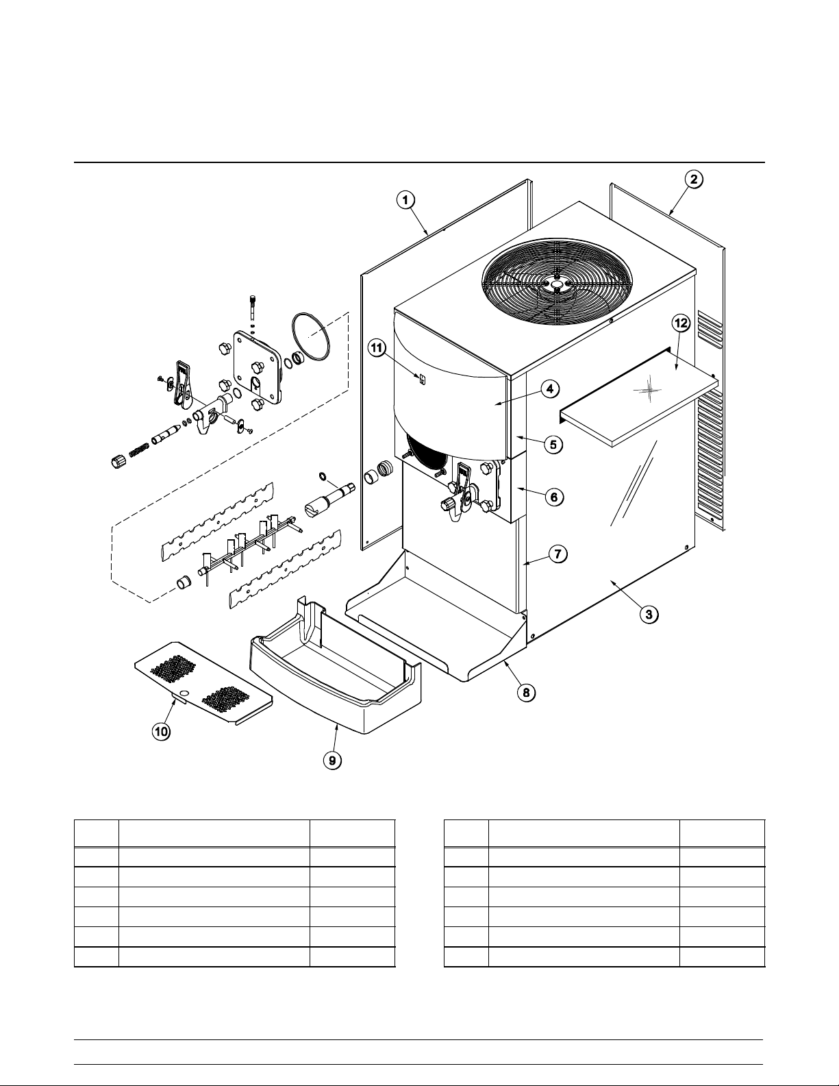
Section 4 Operator Parts Identification
ITEM
1 PANEL A.-SIDE-LEFT C300 X54676-SER
2 PANEL-REAR 054672
3 PANEL-SIDE-RIGHT 054671
4 DISPLAY-LIGHTED 054683-27
5 PANEL-FRONT-UPPER 054669
6 PANEL-FRONT-SHELL 054668
DESCRIPTION PART NO.
090417
Figure 2
8
ITEM DESCRIPTION PART NO.
7 PANEL-FRONT-LOWER 054670
8 SHELF-DRIP TRAY 057938
9 TRAY-DRIP 057738
10 SHIELD-SPLASH 057939
11 SWITCH-ROCKER-OFF-ON 078418
12 FILTER-AIR 15.88L X 15.88H 052779-5
Model C300Operator Parts Identification
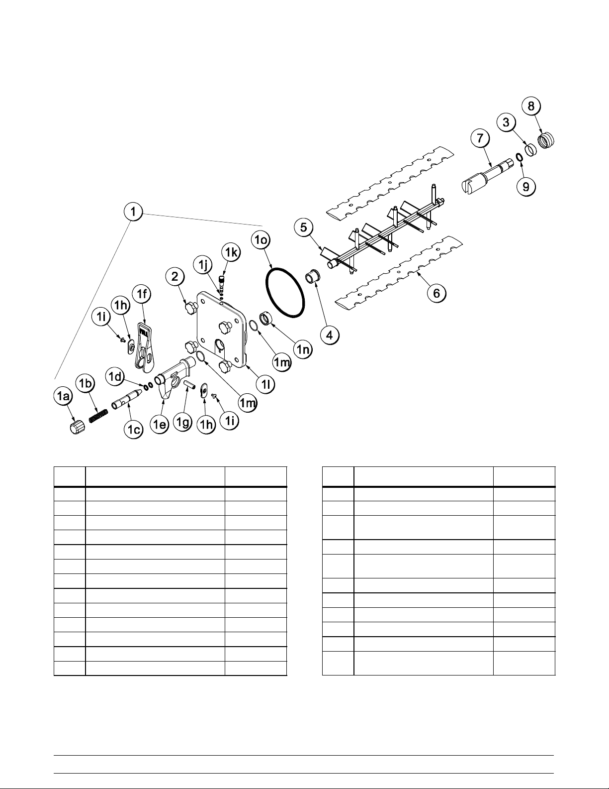
Beater Door Assembly
ITEM
1 DOOR A.-SLUSH PRESS. X39572--BLA
1a CAP-SPOUT-DOOR-FCB-BLK 046191-BLA
1b SPRING-COMP.480X.072X3.0 039320
1c VALVE-DRAW-DOOR-PRESS. 039324
1d O-RING-9/16 OD X .103W 016369
1e SPOUT-DOOR-FCB-BLACK 046190-BLA
1f HANDLE-DRAW-FCB-BLACK 046192-BLA
1g PIN-PIVOT-SPOUT-DOOR 039321
1h SLIDE-HANDLE-DOOR-BLK 046193-BLA
1i SCREW-10-32X3/8PHL 053869
1j O-RING-9/32 OD X 1/16 WALL 029751
1k PLUG-PRIME-SLUSH-PRESS. 039568
1l DOOR-FREEZER-SLUSH-PRES 039573
DESCRIPTION PART NO.
Figure 3
ITEM DESCRIPTION PART NO.
1m O-RING-1.129 ODX.989ID 039219
1n NUT-SPOUT-DOOR-PRESS. 039323
1o O-RING-5-1/4ODX.210W
(DOOR)
2 NUT-STUD 043666
3 BUSHING-BEATER
SHAFT/BOOT SEAL
4 BEARING-FRONT-PRESSURE 039349
5 BEATER-PLASTIC-FCB-PRESS 041182
6 BLADE-SCRAPER-FCB-16INCH 041103
7 SHAFT-BEATER-SLUSH-PRES 039337
8 SEAL-DRIVE SHAFT 032560
9 O-RING-7/8 OD X .139W
(BEATER SHAFT)
017003
042278
025307
100323
Model C300 Operator Parts Identification
9
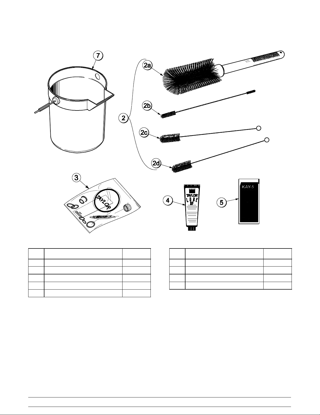
Accessories
ITEM
1 PAIL-MIX 10 QT 013163
2 BRUSH A.-PACKAGE X64275
2a BRUSH-MIX PUMP BODY-3”X7” 023316
2b BRUSH-DOUBLE ENDED 013072
2c BRUSH-REAR BRG 1”DX2“L 013071
DESCRIPTION PART NO.
Figure 4
ITEM DESCRIPTION PART NO.
2d BRUSH-DRAW VALVE 1-1/2”OD 014753
3 KIT A.-TUNE UP X39699
4 LUBRICANT-TAYLOR HI PERF 048232
5 SANITIZER KAY-5 125 PACKETS 041082
10
Model C300Operator Parts Identification
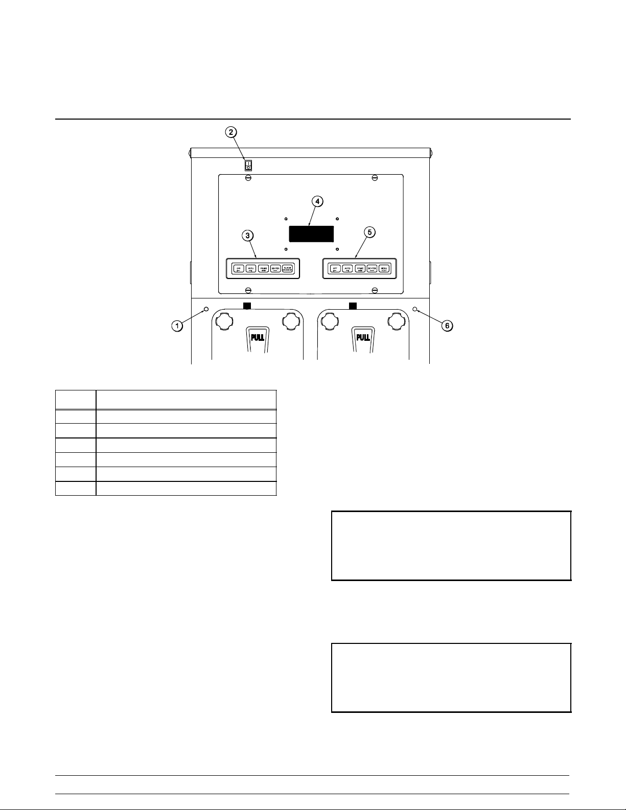
Section 5 Important: To the Operator
Figure 5
ITEM
1 Product Light -- Left Side
2 Control Switch
3 Keypad -- Left Side
4 Liquid Crystal Display
5 Keypad -- Right Side
6 Product Light -- Right Side
DESCRIPTION
Control Switch
The control switch is located at the top left corner of
the control channel. When placed in the ON position,
allows SLUSHTECH operation.
Liquid Crystal Display
The Liquid Crystal Display (LCD) is located on the
front control panel. The LCD is used to show the
current operating mode of the freezing cylinders.
The LCD also indicates whether there is enough
syrup, CO2, and water being supplied to the freezer.
If an error in the machine operation occurs, a
warning tone will sound and the word “FAULT” will
flash on the third line of the display.
Operational Mode Display
The displays below illustrate the Operational Mode
Displays. This information appears on the LCD
during normal operation.
When the unit is plugged into the wall receptacle
and the control switch is in the ON position, this
screen appears.
SAFETY TIMEOUT
ANY KEY ABORT
This display will remain on the LCD for 60 seconds
unless a key is pressed. When any key is pressed
(or 60 seconds passes), the next screen appears.
OFF MODE OFF
OK SYRUP OK
CO2--OK WATER--OK
Note: Syrup, CO2and water are satisfied.
Model C300 Important: To the Operator
11
Pressing the AUTO (-- -->) keys on both sides of the
unit will display this screen.
AUTO MODE AUTO
OK SYRUP OK
CO2--OK WATER--OK
Operator Menu Timeout
If the display is left in the operator menu or any of
the operator menu selections, except for Current
Conditions, the display will return to the system
mode screen 60 seconds after the last keypress.
The Current Conditions screen will be displayed until
manually changed.
Finding Current Fault Conditions
Line 1 indicates the operating mode for each
freezing cylinder.
Line 2 indicates the status of the syrup systems in
each freezing cylinder. As long as syrup is available,
the word “OK” will appear on the LCD. When the
syrup supply is insufficient, the word “OUT” will flash
on the LCD. The same rules apply to the fourth line
which indicates the status of the CO
and the water.
2
The third line of this display is a fault indicator. If an
error in machine operation occurs, the word “FAULT”
will be displayed on the LCD.
BEATER MODE BEATER
OUT SYRUP OUT
-- --FAULT-- -- -- --FAULT-- --
CO2--OUT WATER--OUT
Operator Menu Display
The OPERATOR MENU is used to enter into the
operating screens. To access the OPERATOR
MENU, simply press the MENU (SEL) key. The
cursor will flash under the letter “A”, indicating that
this is screen A. To select a different screen, use the
AUTO (-- -->) and OFF (<-- --) keys to move the
cursor to the desired screen selection and press the
MENU (SEL) key.
Screen B is FAULT DESCRIPTION. The fault
description will indicate if there is a fault in one of the
freezing cylinders. When the actual fault is
corrected, the warning tone will stop. Only item 9
requires pressing the OFF (<-- --) key to clear the
fault message and the warning tone.
Fault Messages
No Fault Found No fault conditions are
apparent.
Beater Overload Beater is out on overload.
Chk Refrig Sys Psi Out on compressor high
pressure cut--out.
Thermistor Short Shorted thermistor probe.
Thermistor Open Open thermistor probe.
Syrup Pressure Low Syrup is no longer present.
CO2 Pressure Low CO2pressure is low.
H2O Pressure Low Water pressure is low.
BRL Not Cooling Freezing cylinder is not
cooling after 5 minutes.
BRLTemp2High Freezing cylinder
temperature is above 120_F
(49_C).
The following are explanations of the possible faults
and the display screens. Lines 2 and 3 indicate the
faults found in freezing cylinders 1 and 2
respectively.
1. NO FAULT FOUND -- No fault conditions are
apparent.
OPERATOR MENU
BCDEFGHI
A
EXIT MENU
<---- ----> SEL
12
FAULT DESCRIPTION
L: NO FAULT FOUND
R: NO FAULT FOUND
CLR +++ SEL
Model C300Important: To the Operator

2. BEATER OVERLOAD -- Beater motor is out on
overload. When this fault occurs, the machine
automatically turns off. The fault clears when
the condition is corrected.
FAULT DESCRIPTION
L: BEATER OVERLOAD
R: BEATER OVERLOAD
CLR +++ SEL
3. CHK REFRIG SYS PSI -- Compressor is out on
high head pressure. When this fault occurs, the
machine automatically turns off. The fault clears
when the condition is corrected.
FAULT DESCRIPTION
L: CHK REFRIG SYS PSI
R: CHK REFRIG SYS PSI
CLR +++ SEL
4. THERMISTOR SHORT -- One or both of the
barrel (freezing cylinder) thermistor probes are
faulty.
FAULT DESCRIPTION
L: THERMISTOR SHORT
R: NO FAULT FOUND
CLR +++ SEL
5. THERMISTOR OPEN -- One or both of the
barrel (freezing cylinder) thermistor probes are
faulty.
6. SYRUP PRESS LOW -- When the syrup out
indicator displays a lack of syrup, the unit will
enter a HOLD mode. At this time, no
refrigeration or product flow from the flow
control will be allowed. Only the beater will
operate. When the syrup is satisfied the unit will
refill the product tank, and then automatically
return to the AUTO mode. The fault message
and the warning tone will clear.
FAULT DESCRIPTION
L: NO FAULT FOUND
R: SYRUP PRESS LOW
CLR +++ SEL
7. CO2PRESSURE LOW -- When the CO2out
indicator displays a lack of CO
internal timer will start. If the CO
, a 60 second
2
is not
2
replenished at the end of the 60 seconds, both
freezing cylinders will shut down and this fault
message will appear. Replenish the CO
2
and
the fault message and warning tone will clear.
FAULT DESCRIPTION
L: CO2 PRESSURE LOW
R: CO2 PRESSURE LOW
CLR +++ SEL
8. H2O PRESSURE LOW -- When the water out
indicator displays a lack of water, a 60 second
internal timer will start. If the water is not
replenished at the end of the 60 seconds, both
freezing cylinders will shut down and this fault
message will appear. Replenish the water and
the fault message and warning tone will clear.
FAULT DESCRIPTION
L: THERMISTOR OPEN
R: NO FAULT FOUND
CLR +++ SEL
Model C300 Important: To the Operator
13
FAULT DESCRIPTION
L: H2O PRESSURE LOW
R: H2O PRESSURE LOW
CLR +++ SEL
 Loading...