

Taylor Freezer BC10, BW11 Operation Manual

Models BC10/BW11
Razzle Blender
Operating Instructions
052544-M
2/1/01

Complete this page for quick reference when service is required:
Taylor Distributor:
Address:
Phone:
Service:
Parts:
Date of Installation:
Information found on the data label:
Model Number:
Serial Number:
Electrical Specs: Voltage Cycle
Phase
Maximum Fuse Size: A
Minimum Wire Ampacity: A
E February, 2001 Taylor
All rights reserved.
052544--M
Taylor Company
The word Taylor and the Crown design
are registered trademarks in the United States
of America and certain other countries.
a division of Carrier Commercial Refrigeration, Inc.
750 N. Blackhawk Blvd.
Rockton, IL 61072

Table of Contents
Section 1 To the Installer 1............................................
Electrical Connections 1.................................................
Foot Pedal Instructions 1................................................
Section 2 To the Operator 2...........................................
Warranty on Taylor Blenders 2............................................
Section 3 Safety 3....................................................
Section 4 Operator Parts Id en t ificatio n 6...............................
BC10 6................................................................
BW11 8................................................................
Accessories 10..........................................................
Optional Dispensers 11...................................................
Optional Large Candy Dispenser Canister Assembly (X53638--1) 17...........
Optional Small Candy Dispenser Canister Assembly (X53638--2) 18............
Section 5 Important: To the Operator 19.................................
Control Switch 19........................................................
Foot Pedal 19...........................................................
Reset Switch 19.........................................................
Splash Guard 19.........................................................
Motor 20................................................................
Permanent Agitator 20....................................................
Candy Dispenser Canisters 20.............................................
Table of Contents Models BC10/BW11

Table of Contents -- Page 2
o
Section 6 Operating Procedures 21.....................................
Mixing Instructions 21....................................................
Cleaning 22.............................................................
Permanent Agitator Cleaning 23...........................................
Sanitizing 23............................................................
Section 7 Parts List 24.................................................
Wiring Diagram 30.......................................................
Note: Continuing research results in steady improvements; therefore, in f o rmation
in this manual is subject to change without notice.
E February, 2001 Taylor
All rights reserved.
052544--M
Taylor Company
The word Taylor and the Crown design
are registered trademarks in the United States
of America and certain other countries.
Table of Contents Models BC10/BW11
a division of Carrier Commercial Refrigerati
750 N. Blackhawk Blvd.
Rockton, IL 61072
Section 1 To the Installer
This machine is designed for indoor use only.
DO NOT install the machine in an area where
a water jet could be used to clean or rinse the machine.
Failure to follow this instruction may result in serious
electrical shock.
Electrical Connections
In the United States, this equipment is intended to be
installed in accordance with the National Electrical
Code (NEC), ANSI/NFPA 70--1987. The purpose of
the NEC code is the practical safeguarding of persons
and property from hazards arising from the use of
electricity. This code contains provisions considered
necessary for safety. Compliance therewith and
proper maintenance will result in an installation
essentially free from hazard!
In all other areas of the world, equipment should be
installed in accordance with the existing local codes.
Please contact your local authorities.
FOLLOW YOUR LOCAL ELECTRICAL CODES!
Each unit requires one power supply. Check the data
labels on the unit for fuse, wire ampacity and electrical
specifications. Refer to the wiring diagram for proper
power connections.
S Stationary appliances which are not
equipped with a power cord and a plug or
other device to disconnect the appliance
from the power source must have an
all--pole disconnecting device with a contact
gap of at least 3 mm installed in the external
installation.
S Appliances that are permanently connected
to fixed wiring and for which leakage
currents may exceed 10 mA, particularly
when disconnected or not used for long
periods, or during initial installation, shall
have protective devices such as a GFI, to
protect against the leakage of current,
installed by the authorized personnel to the
local codes.
S Supply cords used with this unit shall be
oil-resistant, sheathed flexible cable not
lighter than ordinary polychloroprene or
other equivalent synthetic
elastomer-sheathed cord (Code designation
60245 IEC 57) installed with the proper cord
anchorage to relieve conductors from strain,
including twisting, at the terminals and
protect the insulation of the conductors from
abrasion.
Foot Pedal Instructions
CAUTION: THIS EQUIPMENT MUST BE
PROPERLY GROUNDED! FAILURE TO DO SO
CAN RESULT IN SEVERE PERSONAL INJURY
FROM ELECTRICAL SHOCK!
This equipment is provided with a grounding lug
that is to be properly attached to the rear of the frame
by the authorized installer. The installation location is
marked by the equipotential bonding symbol (5021 of
IEC 60417--1) on the removable panel and the frame.
Models BC10/BW11 To th e Installer
To use the momentary foot pedal to control the mixer,
connect the foot pedal to a grounded wall outlet. Plug
the mixer cord into the back of the foot pedal plug. In
this mode, both the control switch and the foot pedal
must be activated. Leave the control switch in the “ON”
position when you wish to use the momentary foot
control. Make sure the foot control is kept where it will
not be activated accidently. The foot guard is an
additional design feature which helps prevent
accidental use of the foot pedal.
080908
1

Section 2 To the Operator
The mixer you have purchased has been carefully
engineered and manufactured to give you dependable
operation. Mixing various candies, cookies, fruits,
nuts, liquid flavors, and other food items into ice cream
or frozen yogurt has made unlimited flavor
combinations and product textures available.
The development of counter and wall mount mixers
have made this unlimited resource available to even
very small retail outlets and to those facilities where
counter space is limited.
The mixer, when properly operated and cared for, will
produce a consistent, quality product. Like all
mechanical products, it will require cleaning and
maintenance. A minimum amount of care and
attention is necessary if the operating procedures
outlined in this manual are followed closely.
This Operator’s Manual should be read before
operating or performing any maintenance on your
equipment. In the event that you should require
technical assistance, please contact your local
authorized Taylor Distributor.
Note: Warranty is valid only if the parts are authorized
Taylor parts, purchased from an authorized Taylor
Distributor, and the required service work is provided
by an authorized Taylor service technician. Taylor
reserves the right to deny warranty claims on
equipment or parts if non--approved parts or
refrigerant were installed in the machine, system
modifications were performed beyond factory
recommendations, or it is determined that the failure
was caused by neglect or abuse.
Note: Constant research results in steady
improvements; therefore, information in this
manual is subject to change without notice.
NSF approvals of the Models BC10 and BW11 were
obtained by the Vita--Mix Corporation, 8615 Usher
Road, Cleveland, Ohio 44138.
completed, and cannot be disposed as unsorted
municipal waste.
The user is responsible for returning the product to the
appropriate collection facility, as specified by your local
code. For additional information regarding applicable
local laws, please contact the municipal facility and/or
local distributor.
Warranty on Taylor Blenders
Caution: Warrantyisvalidonly if the parts are
authorized Taylor parts, purchased from an
authorized T aylor Distributor, and the required
service work is provided by an authorized Taylor
service technician.
Warranty Terms
This warranty covers only defects in material and
workmanship under normal use and service. The
Taylor Distributor will replace those components
that become defective as follows:
S One year warranty on parts and labor
from date of installation of blender.
Not included are the following items:
S External power cords and electrical
grounding.
S Wear items: agitator shaft, splash
shield, and foot pedal.
S Replacements required because of
operator misuse as defined below, fire
or other casualty, normal wear or
deterioration.
Misuse includes the owner’s failure to handle
parts properly, resulting in breakage. Misuse is
also defined as allowing unauthorized service
agents to attempt repairs on units.
If the crossed out wheeled bin symbol is
affixed to this product, it signifies that this product is
compliant with the EU Directive as well as other similar
legislation in effect after August 13, 2005. Therefore,
it must be collected separately after its use is
101021
For validation of warranty, this unit must be
registered at Taylor within thirty (30) days of
installation.
2
Models BC10/BW11To th e Operator
Section 3 Safety
Taylor is concerned about the safety of the operator
when he or she comes in contact with the blender and
its parts. Taylor has gone to extreme efforts to provide
built--in safety features to protect both you and the
service technician. As an example, warning labels
have been attached to the unit to further point out
safety precautions to the operator.
IMPORTANT -- Failure to adhere to the
following safety precautions may result in severe
personal injury or death. Failure to comply with
these warnings may damage the machine and its
components. Component damage will result in
part replacement expense and service repair
expense. SAVE THESE INSTRUCTIONS FOR
FUTURE REFERENCE
To Operate Safely:
DO NOT operate the unit without reading
this operator’s manual. Failure to follow this instruction
may result in equipment damage, poor performance,
health hazards, or personal injury.
DO NOT use a water jet to clean or rinse the
unit. Failure to follow these instructions may result in
serious electrical shock.
This unit is provided with an equipotential
grounding lug that is to be properly attached to the rear
of the frame by the authorized installer. The installation
location is marked by the equipotential bonding
symbol (5021 of IEC 60417-1) on both the removable
panel and the equipments frame.
S DO NOT operate the unit unless it is
properly grounded.
S DO NOT operate the unit with larger fuses
than specified on the data label.
S DO NOT attempt any repairs unless the
main power supply to the unit has been
disconnected. Note: Contact your local
authorized Taylor Distributor for service.
S DO NOT use this appliance outdoors.
S DO NOT operate this appliance if the power
cord is damaged.
S Stationary appliances which are not
equipped with a power cord and a plug or
another device to disconnect the appliance
from the power source must have an all-pole
disconnecting device with a contact gap of
at least 3mm installed in the external
installation.
S Appliances that are permanently connected
to fixed wiring and for which leakage
currents may exceed 10 mA, particularly
when disconnected or not used for long
periods, or during initial installation, shall
have protective devices such as a GFI, to
protect against the leakage of current,
installed by the authorized personnel to the
local codes.
S Supply cords used with this unit shall be
oil-resistant, sheathed flexible cable not
lighter than ordinary polychloroprene or
other equivalent synthetic
elastomer-sheathed cord (Code designation
60245 IEC 57) installed with the proper cord
anchorage to relieve conductors from strain,
including twisting, at the terminals and
protect the insulation of the conductors from
abrasion.
Failure to follow these instructions may result in
electrocution. Contact your local authorized Taylor
Distributor for service.
080908
Models BC10/BW11 Safety
3
S DO NOT allow children or untrained
personnel to operate this machine.
S DO NOT operate the unit unless all service
panels and access doors are restrained with
screws.
S AVOID contact with the agitator shaft and
other moving parts.
S Make sure the splash guard is installed prior
to operating the appliance.
S DO NOT disassemble or install parts unless
the control switch is in the “OFF” position.
S Always use the foot pedal guard, and avoid
accidental use of the foot pedal. When using
the foot pedal, make sure the appliance is
located where accidental contact with the
pedal is not likely. When the mixer is not in
use, place the front switch in the “OFF”
position to avoid accidental use of the pedal.
(Note: Some international units are not
equipped with this feature.)
Failure to follow these instructions may result in severe
personal injury from hazardous moving parts.
DO NOT operate this appliance if it
malfunctions or is damaged in any way. Failure to
follow this instruction may result in injury or component
damage.
DO NOT use attachments not recommended
or sold by Taylor. Doing so may cause fire, electric
shock, injury, or equipment damage.
Make sure the mixer is sitting or mounted
solidly on a sturdy surface during operation. Failure to
comply may result in injury or equipment damage.
WARNING!
Some consumers are highly allergic to
peanuts, peanut oil, and peanut dust. In
some severe cases, peanut allergy
reactions can cause death. When
blending product with peanuts, make
sure excess product is cleaned from the
agitator shaft to eliminate the fear of
product carryover.
DO NOT allow the power cord to hang over
the edge of the counter or touch hot surfaces. Failure
to comply may result in an electrical fire.
NOISE LEVEL: Airborne noise emission does not
exceed 78 dB(A) when measured at a distance of 1.0
meter from the surface of the machine and at a height
of 1.6 meters from the floor.
4
Models BC10/BW11Safety

Notes:
Models BC10/BW11 Safety
5
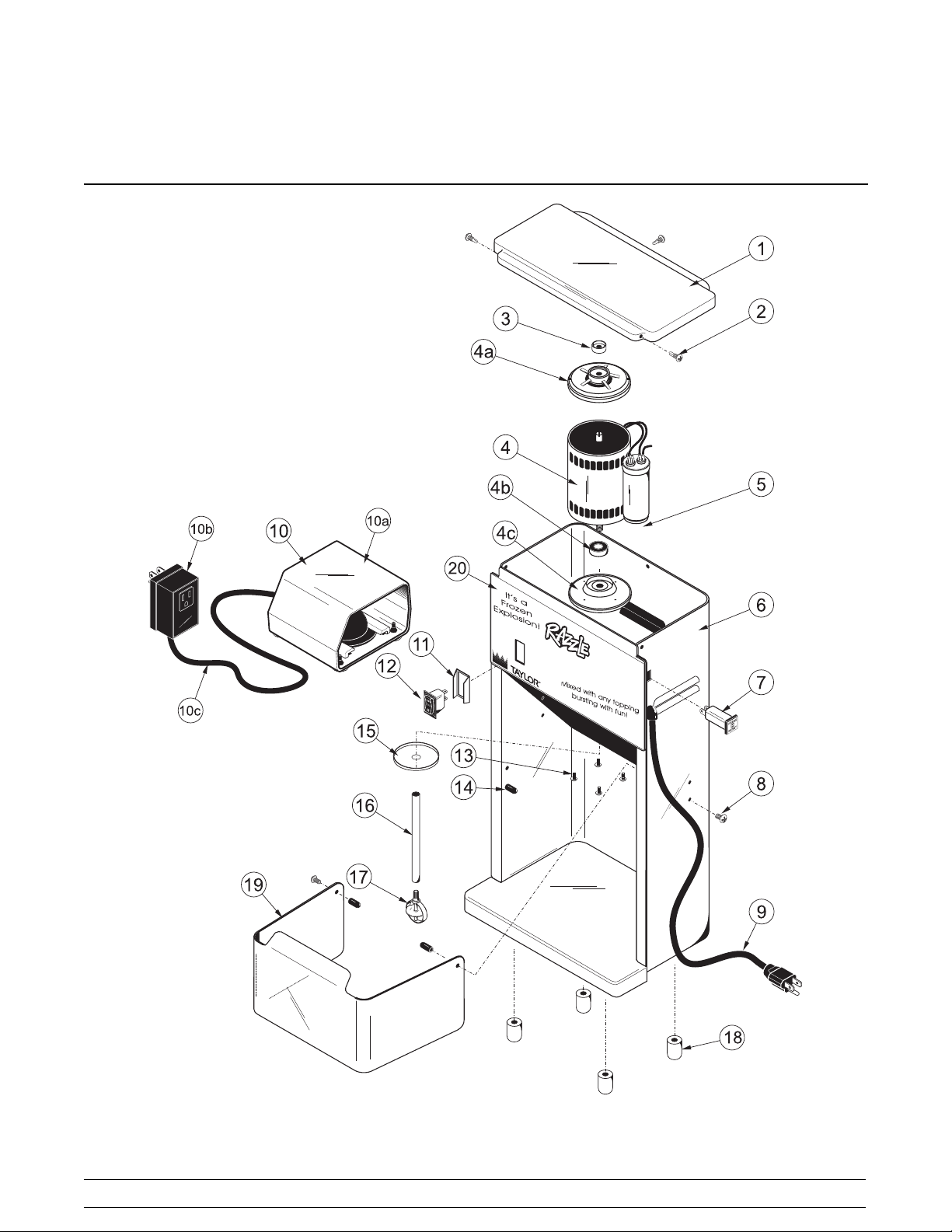
Section 4 Operator Parts Identification
BC10
6
Models BC10/BW11Operator Parts Identification

BC10 Exploded View Parts Id en tificatio n
ITEM DESCRIPTION PART NO.
1 CAP-MIXER 051484
2 SCREW-MIXER-RETAINERCAP 051487
3 BRAKE (SEAL)MIXER 051485
MOTOR-MIXER (120V) 051481-12
4
MOTOR-MIXER (220/240V) 051481-27
4a PLATE-MOTOR MOUNTING TOP 051481-4
4b BEARING-MIXER MOTOR 051481-2
4c PLATE-MOTOR MTG. BOTTOM 051481-1
CAPACITOR-MIXER (220/240V) 051483
5
CAPACITOR-MIXER (120V) 051482
6 FRAME-MIXER-STAINLESSSTL 051480
BREAKER-CIRCUIT-MIXER-
3A-120V
7
BREAKER-CIRCUIT-MIXER-
5A-220/ 240V
8 SCREW-MIXER-MTGPIVOT PIN 051508
9 CORD-MIXER-18/3GROUNDED 051491
10 PEDAL-FOOT-MIXER-115V 052451
10* PEDAL-FOOT-MIXER-220V 053192
10a TRANSMITTER FOOT PEDAL 052451-1
10b CONTROLLER-FOOT PEDAL-
115V
051490
051489
052451-2
ITEM DESCRIPTION PART NO.
10b* SWITCH-PRESS.-FOOT PEDAL-
220V
10c TUBE-AIR-FOOT PEDAL 052451-3
11 GUARD-SWITCH-MIXER 051505
12 SWITCH-ROCKER-MIXER 051488
13 SCREW-MIXER-MOTORMTG 051493
14 PIN PIVOT-MIXER 051507
15 SLINGER-MIXER 051494
16 SHAFT-MIXER-AGITATOR-EXT 051495
17 AGITATOR-MIXER-PERM SOFT 051497
18 FOOT A.-MIXER-PLUGGED 051500
19 GUARD-SPLASH-MIXER 051499
20 LABEL-MIXER-COUNTER-
RAZZLE
* CAP-CRIMP-MIXER 051504
* JUMPER WIRES-MIXER 051486
* MANUAL-OPERATOR-MIXER 052544-M
* RELIEF-STRAIN-MIXER-R ANGLE 051492
* TAB INSULATOR-MIXER
(CAPACITOR)
* TIES-CABLE-MIXER
(CAPACITOR)
* NOT SHOWN
053192-1
052250
051509
051502
Models BC10/BW11 Operator Parts Identification
7
 Loading...