

Taylor Freezer 794 General Manual
Item No.
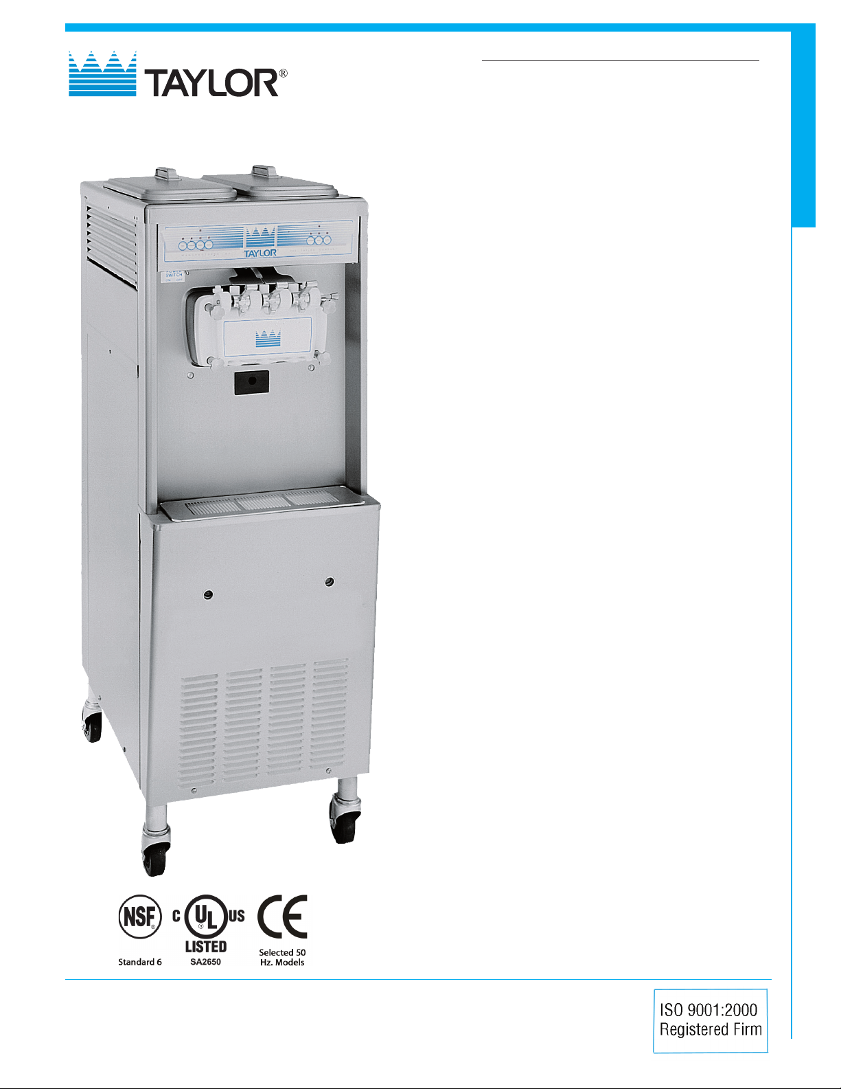
794
Soft Serve Freezer
Twin Twist
Features
Offer all the popular soft serve variations from low or nonfat ice creams to custards, yogurt and sorbet. Serve two
separate soft serve flavors, or an equal combination of both
in a twist.
Freezing Cylinder
Two, 3.4 quart (3.2 liter).
Mix Hopper
Two, 14 quart (13.2 liter). Separate hopper refrigeration (SHR) maintains mix
below 41ºF (5ºC) during Auto and Standby modes.
Indicator Lights
Mix Low light alerts operator to add mix.
794
Electronic Controls
SoftechTM is our exclusive microprocessor based master control that
regulates refrigeration by measuring product viscosity to maintain consistent
quality.
Standby
During long no-use periods, the standby feature maintains safe product
temperatures in the mix hopper and freezing cylinder.
Optional Drain Assembly
An optional factory installed drain assembly, with funnel, is avaliable to
simplify the cleaning process. A drain line, connected under the drip tray
connects to a 1” FPT coupling in the base pan to drain rinse water to a floor
drain.
Two Locking Casters
Front casters have a locking feature for operators to lock to maintain
equipment in place. The locking casters can be released to move the
equipment for cleaning.
Freezer Door
A specially designed thermo-plastic door allows quick ejection of product
with a simple movement of the draw handle. Self closing draw handles are
standard.
Door Interlock System
Protects the operator from injury as the beater will not operate without the
dispensing door in place.
Rockton, Illinois 61072
800-255-0626
Phone 815-624-8333 Fax 815-624-8000
www.taylor-company.com
e-mail: info@taylor-company.com
International Office
Taylor Company S.r.l.
Roma, Italy
Tel: +39-06-420-12002 Fax: +39-06-420-12034
e-mail: romeoff@taylor-company.com
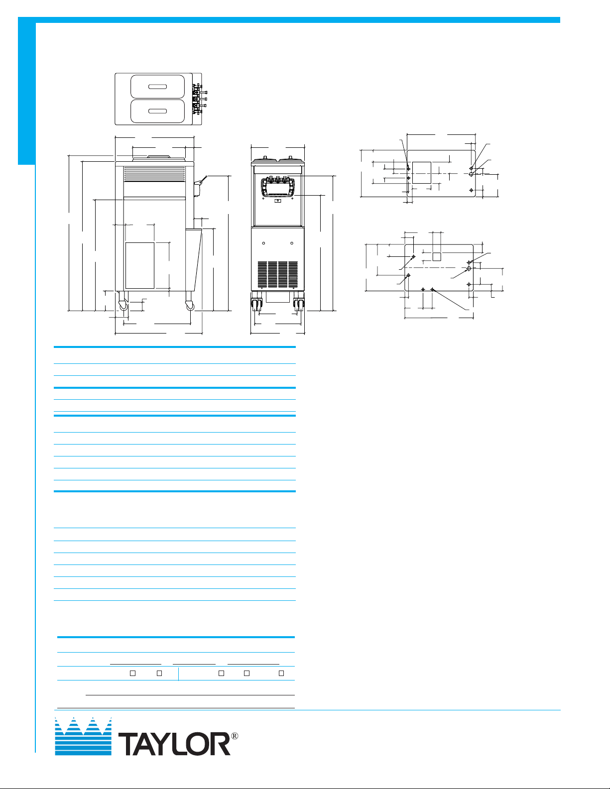
794 Soft Serve Freezer
794
30-3/16
(767)
60
(1524)
57-9/16
(1462)
43
(1092)
4-31/32
3-29/32
(126)
(99)
7-3/4
(197)
OUT
AIR
11
(279)
AIR IN
26-7/16
(671)
3-1/2
(89)
20-3/16
(513)
17-19/32
1-3/32
(447)
(28)
33-3/16
(843)
3-3/8
(86)
(76)
31-7/8
(810)
51-1/16
(1297)
3
17-1/2
(445)
20-1/4
(514)
14-5/16
(364)
20-7/16
(519)
Weights lbs. kgs.
Net 640 290.3
Crated 699 317.1
cu. ft. cu. m.
Volume 48.9 1.38
Dimensions in. mm.
Width 20-7/16 519
Depth 33-13/16 859
Height 60 1524
Floor Clearance 7-3/4 197
*Mounted on standard casters
Electrical Maximum Minimum Poles (P)
Fuse Size Circuit Ampacity Wires (W)
Left Right Left Right
208-230/60/1 Air 35 35 27 23 2P 3W
208-230/60/1 Water 35 35 25 23 2P 3W
208-230/60/3 Air 25 20 19 15 3P 4W
208-230/60/3 Water 20 20 17 15 3P 4W
220-240/50/1 Air 30 25 23 19 2P 3W
380-415/50/3N~ Air 12 10 12 8 4P 5W
This unit may be manufactured in other electrical characteristics. Refer to the
local Taylor Distributor for availability.
(For exact electrical information, always refer to the data label of the unit.)
Bidding Specs
Electrical: Volt Hz ph
Neutral: Yes No Cooling: Air Water NA
Options:
Taylor Company,
Rockton, Illinois 61072
815-624-8333 800-255-0626 Fax 815-624-8000
www.taylor-company.com
30
(762)
1-7/8
(48)
4-25/32
AIR
(121)
OUT
8-1/8
(206)
12-1/4
(311)
3-1/2
(89)
(OPTIONAL)
DRAIN HOLE
1” F.P. T. THREAD
8
(203)4(102)
FIGURES IN PARENTHESES INDICATE MILLIMETERS.
4-19/32
(117)
FAN
3-1/2
C
L
(89)
C
L
30
(762)
1-3/32 (28)
ELECTRICAL
HOLE (2)
DRAIN HOLE
1” F.P. T. COUPLING
9-1/2
(241)
9-29/32
(252)
2-29/32
(74)
3-21/32
(93)
1-3/32 (28)
ELECTRICAL
HOLE (2)
9-1/2
(241)
9-29/32
(252)
2-29/32
1-7/8
(74)
(48)
FAUCET COUPLINGS (2)
AIR COOLED
WATER COOLED
TOP VIEW BASE - OPERATOR END
44-1/8
(1121)
51-1/16
(1297)
FAUCET COUPLINGS (2)
5-5/16
(51)
(135)
20-7/16
(519)
9-3/8
4
(238)
(102)
3-27/32 (98)
5-11/32
(136)
13-17/32
(344)
WATER IN
20-7/16
(519)
WATER OUT
1-19/32
(40)
2
11/16
(17)
2-5/16
(59)
Specifications
Electrical
Two dedicated electrical connections are required. See the Electrical chart
for the proper electrical requirements. Manufactured to be permanently
connected. Consult your local Taylor distributor for cord & receptacle
specifications as local codes allow.
Beater Motor
Two, 1.5 HP.
Refrigeration System
Two, 9,500 BTU/hr. R404A.
Separate Hopper Refrigeration (SHR), One, 400 BTU/hr. R134a.
(BTUs may vary depending on compressor used.)
Air Cooled
Minimum 3” (76 mm) around all sides. Install the deflector provided to
prevent recirculation of warm air. Minimum air clearances must be met to
assure adequate air flow for optimum performance.
Water Cooled
Water inlet and drain connections under side of base 1/2” FPT.
Options
• Cone Dispenser
• Drain with Funnel
• Draw Valve Lock Kit
• Faucet
• Mix Low Chime
• Sneeze Guard
• Syrup Rail Kit (side mount)
Continuing research results in steady improvements; therefore,
these specifications are subject to change without notice.
044658-ADV 11/11
 Loading...