


Models 60/62
Shake Freezers
Operating Instructions
051059-M
4/00
Complete this page for quick reference when service is required:
Taylor Distributor:
Address:
Phone:
Service:
Parts:
Date of Installation:
Information found on the data label:
Model Number:
Serial Number:
Electrical Specs: Voltage Cycle
Phase
Maximum Fuse Size: A
Minimum Wire Ampacity: A
EApril, 2000 Taylor
All rights reserved.
051059--M
Tayl o r
The word Taylor and the Crown design
are registered trademarks in the United States
of America and certain other countries.
a division of Carrier Commercial Refrigeration, Inc.
750 N. Blackhawk Blvd.
Rockton, IL 61072

Table of Contents
______________________________________________________________________________
Section 1 To the Installer 1............................................
Water Connections (Water Cooled Units Only) 1............................
Air Cooled Units 1.......................................................
Electrical Connections 1.................................................
Section 2 To the Operator 2...........................................
Compressor Warranty Disclaimer 2.......................................
Section 3 Safety 3....................................................
Section 4 Operator Parts Identification 4...............................
Section 5 Important: To the Operator 8.................................
Control Switch 8........................................................
Dial Light 8.............................................................
Indicator Light (“Mix Low”) 8..............................................
Indicator Light (“Mix Out”) 8..............................................
Reset Mechanism 9.....................................................
Consistency Control* 9..................................................
Spinner Rinse Switch* 9.................................................
Auto Lift Switch (Model 60 Only)* 9........................................
Foot Pedal (Model 60 Only) 9............................................
Flavor Selector Switch* 9................................................
Section 6 Operating Procedures 10.....................................
Assembly 10............................................................
Sanitizing 15............................................................
Priming 16..............................................................
Syrup System 18.........................................................
Drawing Product 20......................................................
Closing Procedures 21...................................................
Draining Product From The Freezing Cylinder 21............................
Table of Contents Models 60 & 62

Table of Contents -- Page 2
Rinsing 21..............................................................
Cleaning 22.............................................................
Disassembly 22..........................................................
Brush Cleaning 23.......................................................
Sanitizing Syrup System 23...............................................
Section 7 Important: Operator Checklist 26..............................
During Cleaning and Sanitizing: 26.........................................
Troubleshooting Bacterial Count: 26........................................
Regular M aintenance Checks: 26..........................................
Winter Storage 27........................................................
Section 8 Troubleshooting Guide 28....................................
Section 9 Parts Replacement Schedule 32...............................
Section 10 Parts List 33.................................................
Wiring Diagrams 44......................................................
Note: Continuing research results in steady improvements; therefore, inf ormation
in this manual is subject to change without notice.
Models 60 & 62 Table of Contents
Section 1 To the Installer
This machine is designed for indoor use only.
DO NOT install the machine in an area where
a water jet could be used to clean or rinse the machine.
Failure to follow this instruction may result in serious
electrical shock.
Water Connections
(Water Cooled Units Only)
An adequate cold water supply must be provided with
a hand shut-off valve. On the underside rear of the
base pan, two 3/8” I.P.S. water connections for inlet
and outlet have been provided for easy hook-up. 1/2”
inside diameter water lines should be connected to the
machine. (Flexible lines are recommended, if local
codes permit.) Depending on local water conditions, it
may be advisable to install a water strainer to prevent
foreign substances from clogging the automatic water
valve. There will be only one water “in” and one water
“out” connection. DO NOT install a hand shut-off valve
on the water “out” line! Water should always flow in this
order: first, through the automatic water valve; second,
through the condenser; and third, through the outlet
fitting to an opentrapdrain.
Air Cooled Units
Electrical Connections
Each freezer requires one power supply for each data
label. Check the data label on the freezer for fuse,
circuit ampacity and electrical specifications. Refer to
the wiring diagram provided inside of the control box,
for proper power connections.
In the United States, this equipment is intended to be
installed in accordance with the National Electrical
Code (NEC), ANSI/NFPA 70--1987. The purpose of
the NEC code is the practical safeguarding of persons
and property from hazards arising from the use of
electricity. This code contains provisions considered
necessary for safety. Compliance therewith and
proper maintenance will result in an installation
essentially free from hazard!
In all other areas of the world, equipment should be
installed in accordance with the existing local codes.
Please contact your local authorities.
Stationary appliances which are not equipped with a
power cord and a plug or other device to disconnect
the appliance from the power source must have an
all--pole disconnecting device with a contact gap of at
least 3 mm installed in the external installation.
CAUTION: THIS EQUIPMENT MUST BE
PROPERLY GROUNDED! FAILURE TO DO SO
CAN RESULT IN SEVERE PERSONAL INJURY
FROM ELECTRICAL SHOCK!
Air cooled units require adequate clearance around
the sides of the freezer to allow for adequate air flow
across the condenser.
Counter Models: 6” (152 mm) minimum air space on
both sides. It is recommended to place the rear of the
unit against the wall to prevent recirculation of warm
air.
Console Models: 3” (76 mm) minimum air space on
each side and rear of unit when air deflector is
employed.
Failure to allow adequate clearance can reduce the
refrigeration capacity of the freezer and possibly
cause permanent damage to the compressor.
Models 60 & 62 To th e Installer
Beater rotation must be clockwise as viewed looking
into the freezing cylinder.
Note: The following procedures should be performed
by a trained service technician.
To correct rotation on a three-phase unit, interchange
any two incoming power supply lines at freezer main
terminal block only.
To correct rotation on a single-phase unit, change the
leads inside the beater motor. (Follow diagram printed
on motor.)
Electrical connections are made directly to the
terminal block provided in the main control box
mounted on the right hand side of the freezer.
040809
1

Section 2 To the Operator
The freezer you have purchased has been carefully
engineered and manufactured to give you dependable
operation. The Taylor Models 60 and 62, when
properly operated and cared for, will produce a
consistent quality product. Like all mechanical
products, these machines will require cleaning and
maintenance. A minimum amount of care and
attention is necessary if the operating procedures
outlined in this manual are followed closely.
This Operator’s Manual should be read before
operating or performing any maintenance on your
equipment. The Taylor Models 60 and 62 will NOT
eventually compensate and correct for any errors
during the set-up or filling operations. Thus, the initial
assembly and priming procedures are of extreme
importance. It is strongly recommended that
personnel responsible for the equipment’s operation,
both assembly and disassembly, sit down together and
go through these procedures in order to be properly
trained and to make sure that no misunderstandings
exist.
In the event you should require technical assistance,
please contact your local authorized Taylor Distributor.
If the crossed out wheeled bin symbol is
affixed to this product, it signifies that this product is
compliant with the EU Directive as well as other similar
legislation in effect after August 13, 2005. Therefore,
it must be collected separately after its use is
completed, and cannot be disposed as unsorted
municipal waste.
The user is responsible for returning the product to the
appropriate collection facility, as specified by your local
code.
For additional information regarding applicable local
laws, please contact the municipal facility and/or local
distributor.
Compressor Warranty Disclaimer
The refrigeration compressor(s) on this machine are
warranted for the term indicated on the warranty card
accompanying this machine. However, due to the
Montreal Protocol and the U.S. Clean Air Act
Amendments of 1990, many new refrigerants are
being tested and developed, thus seeking their way
into the service industry. Some of these new
refrigerants are being advertised as drop-in
replacements for numerous applications. It should be
noted that, in the event of ordinary service to this
machine’s refrigeration system, only the refrigerant
specified on the affixed data label should be used.
The unauthorized use of alternate refrigerants will void
your compressor warranty . It will be the owner’s
responsibility to make this fact known to any technician
he employs.
It should also be noted that Taylor does not warrant the
refrigerant used in its equipment. For example, if the
refrigerant is lost during the course of ordinary service
to this machine, Taylor has no obligation to either
supply or provide its replacement either at billable or
unbillable terms. Taylor does have the obligation to
recommend a suitable replacement if the original
refrigerant is banned, obsoleted, or no longer available
during the five year warranty of the compressor .
Taylor will continue to monitor the industry and test
new alternates as they are being developed. Should a
new alternate prove, through our testing, that it would
be accepted as a drop-in replacement, then the above
disclaimer would become null and void. To find out the
current status of an alternate refrigerant as it relates to
your compressor warranty, call the local T aylor
Distributor or the Taylor Factory. Be prepared to
provide the Model/Serial Number of the unit in
question.
070112
2
Models 60 & 62To th e Operator
Section 3 Safety
We at Taylor are concerned about the safety of the
operator when he or she comes in contact with the
freezer and its parts. Taylor has gone to extreme
efforts to design and manufacture built-in safety
features to protect both you and the servicetechnician.
IMPORTANT -- Failure to adhere to the
following safety precautions may result in severe
personal injury. Failure to comply with these
warnings may damage the machine and its
components. Component damage will result in
part replacement expense and service repair
expense.
To Operate Safely:
S DO NOT allow untrained personnel to
operate this machine.
S DO NOT operate the freezer unless all
service panels and access doors are
restrained with screws.
S DO NOT remove the door, beater, scraper
blades, drive shaft or torque rotor shaft
unless the power switch is in the “OFF”
position.
Failure to follow these instructions may result in
contaminated product or severe personal injury to
fingers or hands from hazardous moving parts.
DO NOT operate the freezer without reading
this operator’s manual. Failure to follow this instruction
may result in equipment damage, poor freezer
performance, health hazards, or personal injury.
S DO NOT operate the freezer unless it is
properly grounded.
S DO NOT attempt any repairs unless the
main power supply to the freezer has been
disconnected.
S DO NOT operate the freezer with larger
fuses than specified on the freezer data
label.
Failure to follow these instructions may result in
electrocution or damage to the machine. Contact your
local authorized Taylor Distributor for service.
DO NOT use a water jet to clean or rinse the
freezer. Failure to follow this instruction may result in
serious electrical shock.
S DO NOT put objects or fingers in door spout
or spinner housing.
S USE EXTREME CAUTION when removing
the beater assembly.
Failure to follow these instructions may result in
contaminated product or personal injury from blade
contact.
DO NOT obstruct air intake and discharge openings:
Counter Models: 6” (152 mm) minimum air space on
both sides. Place the rear of the unit against the wall
to prevent recirculation of warm air.
Console Models: 3” (76 mm) minimum air space on
each side and rear of unit when air deflector is
employed.
Failure to follow this instruction may cause poor
freezer performance and damage to the machine.
These freezers are designed to operate indoors, under
normal ambient temperatures of 70_-- 7 5 _F
(21_-- 2 4 _C). The freezers have successfully
performed in high ambient temperatures of 104_F
(40_C) at reduced capacities.
NOISE LEVEL: Airborne noise emission does not
These freezers must be placed on a level
surface. Failure to comply may result in personal injury
or equipment damage.
Models 60 & 62 Safety
exceed 78 dB(A) when measured at a distance of 1.0
meter from the surface of the machine and at a height
of 1.6 meters from the floor.
070112
3
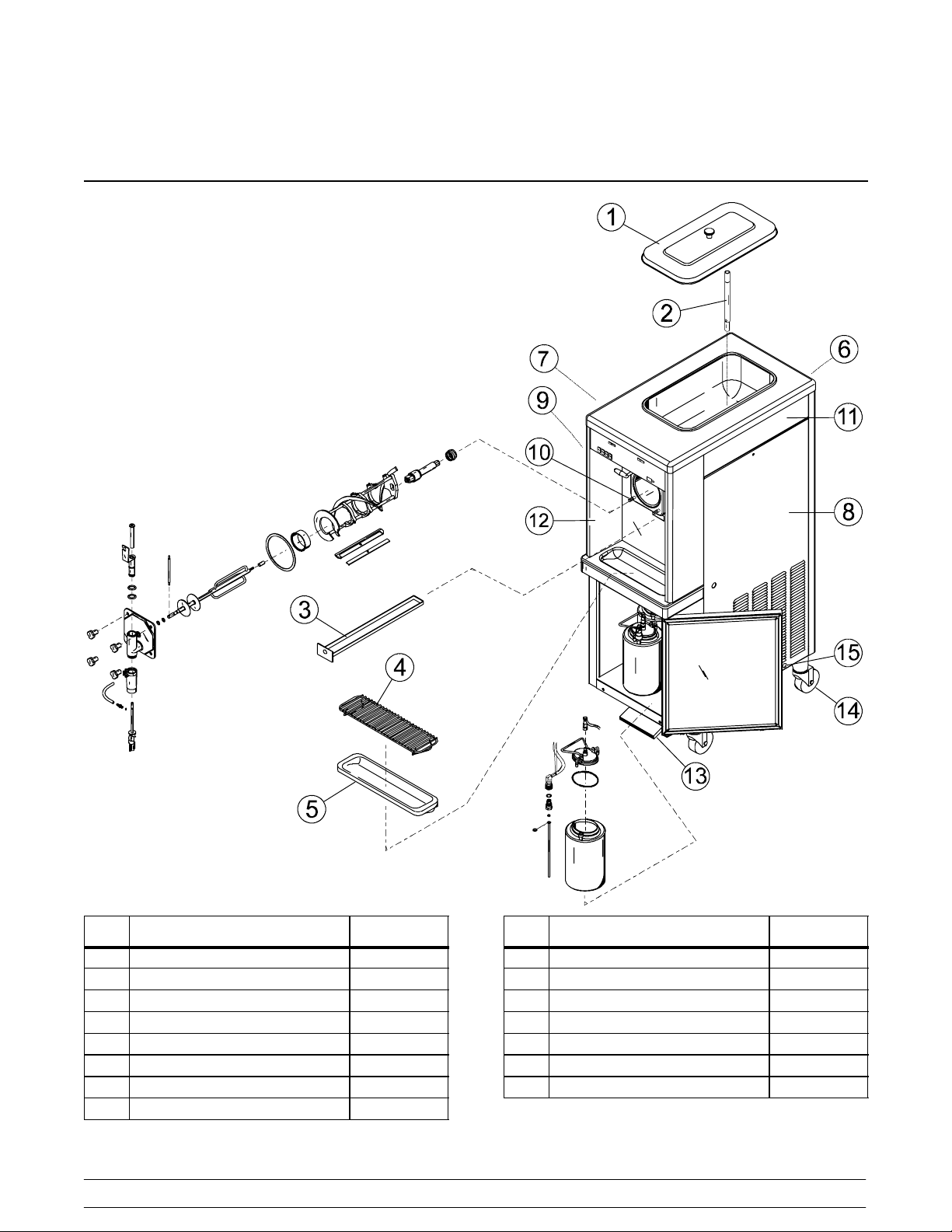
Section 4 Operator Parts Identification
Model 60
Item Description Part No.
1 Cover A.-Hopper-Std. X38458-SER
2 Tube-Feed-1/4 Hole 015176-5
3 Pan-Drip 19-1/2 Long 035034
4 Shield-Splash-Wire 13-11/16 L 046177
5 Tray-Drip 14.8 046275
6 Panel-Rear w/Louvers 026980-SP
7 Louver-Side 013631
8 Panel A.-Side R X48286
Item Description Part No.
9 Panel A.-Side L X48285
10 Stud-Nose Cone 5/16-18 x 3/8-1 011390
11 Panel-Side Upper 042317
12 Panel A.-Front X46634
13 Pedal A.-Foot X48826
14 Caster-Swv 5/8 Stem 4” Wheel 018794
15 Screw-1/4-20 x 3/8 Rhm-Stnls 011694
4
Models 60 & 62Operator Parts Identification
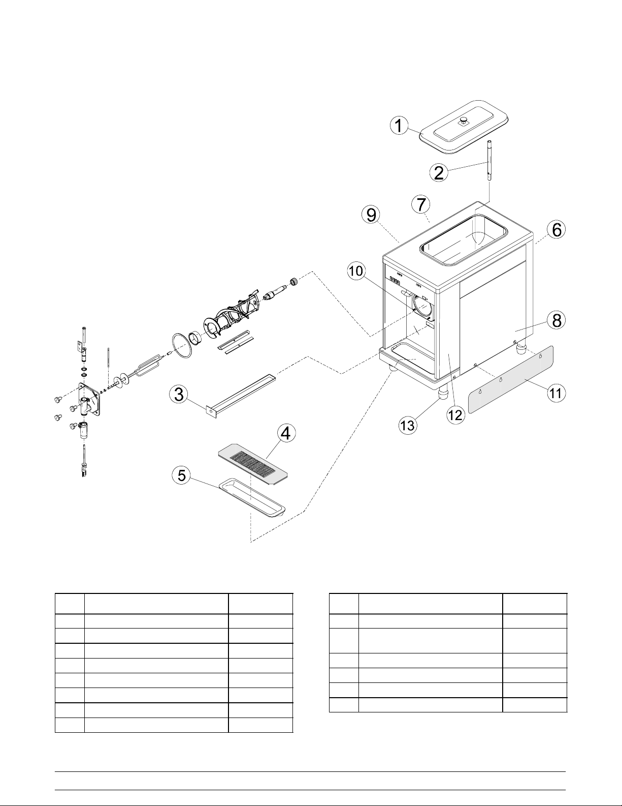
Model 62
Item Description Part No.
1 Cover A.-Hopper-Std. X38458-SER
*1a Knob-Mix Cover 025429
2 Feed Tube 015176-5
3 Pan-Drip 19-1/2 Long 035034
4 Shield-Splash 022765
5 Tray-Drip 16-7/8 L x 5-1/8 020157
6 Panel-Rear 039021
7 Louver-Side 013631
Models 60 & 62 Operator Parts Identification
Item Description Part No.
8 Panel-Side-Right 050024
Panel A.-Side Left
9
Panel-Side Upper
10 Stud-Nose Cone 5/16-18 x 3/8-1 011390
11 Skirt-Air Flow 049069
12 Panel A.-Front X49996
13 Leg-4” SS w/O-ring 013458
*Not Identified
5
X50023
042317
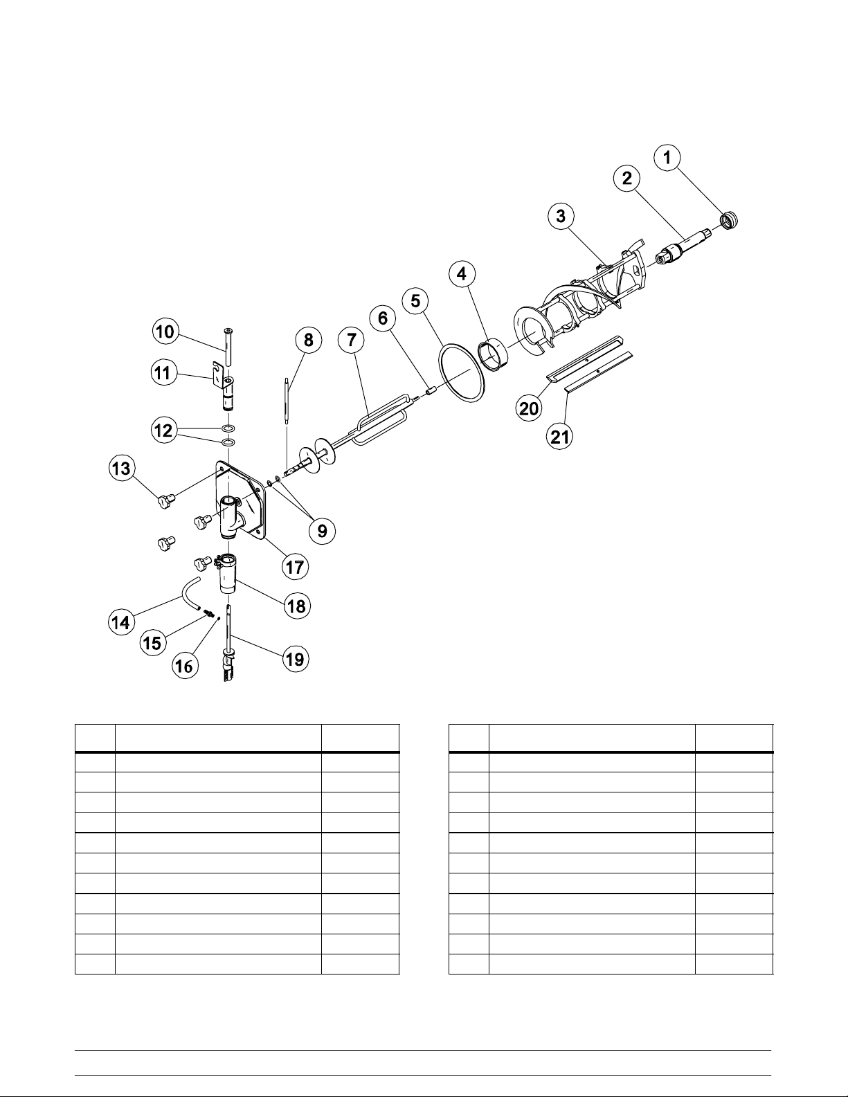
Beater Assembly
Item Description Part No.
1 Seal-Drift Shaft 032560
2 Drive Shaft 035527
3 Beater Assembly X46233
4 Front Bearing 013116
5 Door Gasket 016672
6 Bearing Guide 014496
7 Torque Shaft Assembly X17381
8 Torque Arm 014500
9 O-Ring-Torque Shaft 018550
10 Spinner Bearing 017032
11 Draw Valve Assembly X46671
Item Description Part No.
12 O-Ring-Draw Valv e 013029
13 Stud Nut 021508
14 Tube-Vinyl (Bulk Item #R30314) 020940
15 Fitting-QD Male Insert (M 60 Only) 036296
16 O-Ring (M 60 Only) 016272
17 Freezer Door Assembly X17373
18 Spinner Housing 017269
19 Spinner Blade Assembly X35570
20 Scraper Blade 046237
21 Clip-Scraper Blade 046238
*22 Female Fitting (M 60 Only) 036295
*Not Shown
6
Models 60 & 62Operator Parts Identification
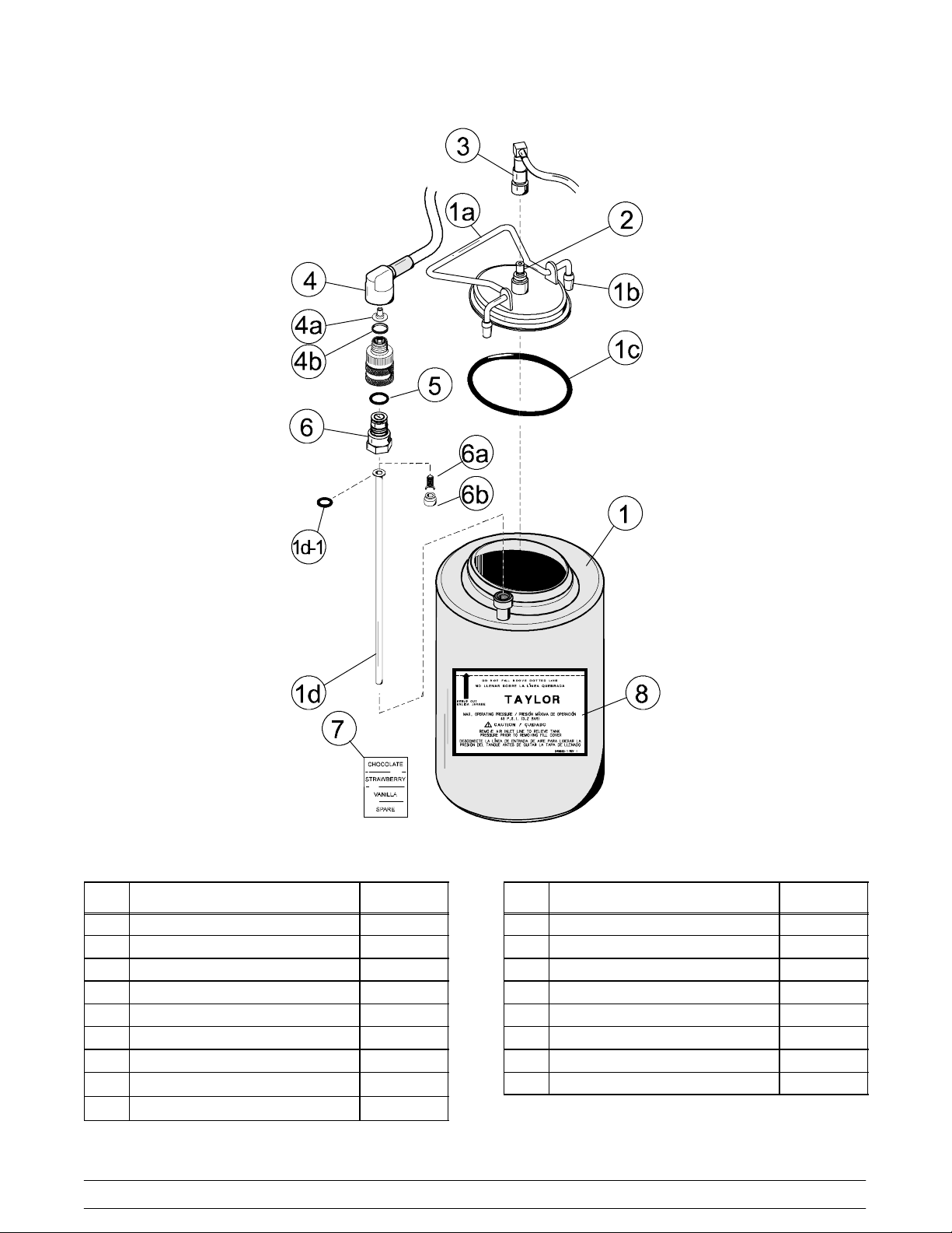
Syrup Tank
Item Description Part No.
1 Tank-Syr-4 Qt. 045533
1a Cover-T ank 8 Qt. w/Inlet Ftg. 035759-1
1b Tip-Nylon-White Translucent 042747
1c O-Ring-3.437 ID x .275 W 016037
1d Tube-Dip-4 Qt. Syr. Tank w/O-ring 015441--7
1d-1 O-Ring-.291 ID x .080 W 018550
2 Plug-Q.D. CO2 1/8 MP 021077
3
Socket-Q.D. CO2 90_ 1/4 Barb
4
Socket-Q.D. Liq.- 90_ 1/4 Barb
021524
021026
Models 60 & 62 Operator Parts Identification
Item Description Part No.
*4a Restrictor-Syrup 025816
4b Gasket-Rubber 023551
5 O-Ring-5/8 OD x .103 W 016030
6 Plug-Q.D. Liq. 3/4-18 FP 021081
6a Valve A.-Q.D. Plu g 021081-2
6b Insert 021081-1
7 Decal-Set 4 Syrup Flavor 021523
8 Decal-Syrup Tank Instruction 045533-1
*Not used on chocolate
7
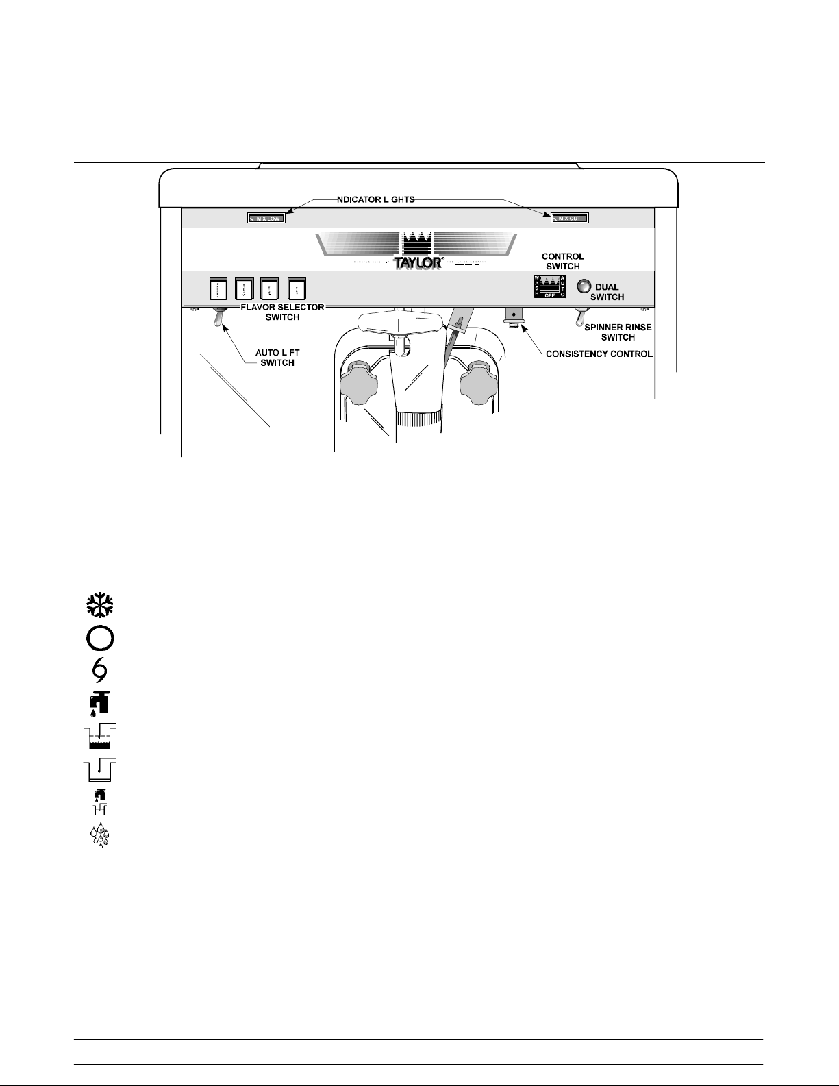
Section 5 Important: To the Operator
To better communicate in the International arena, the
words on many of our operator switches and buttons
have symbols to indicate their functions. Your Taylor
equipment is designed with these International
symbols.
The following chart identifies the symbol definitions
used on the operator switches:
= The “ON/AUTO” button.
= The “OFF” button.
= The “MIX” button.
= The “WASH” button.
= The “MIX LOW” button.
= The “MIX OUT” button.
= The “FILL” button.
= The “RINSE” button.
Control Switch
The center position is “OFF”. The left position is
“WASH”, which activates the beater motor only. The
right position is “AUTO”. It activates the beater motor
and the refrigeration system. To activate the
refrigeration system, raise the draw arm momentarily.
Dial Light
A red dial light is located on the right side of the control
switch. When the control switch is in the “AUTO”
position, this light will come on, indicating that the
refrigeration system is operable.
Indicator Light (“Mix Low”)
The mix low indicator light is located on the front of the
machine directly above the flavor selector switch.
When the light flashes, it indicates that the mix hopper
has a low supply of mix and should be refilled as soon
as possible. If mix is not added, a starved freezing
cylinder will cause damage to the beater, blades, and
drive shaft.
Indicator Light (“Mix Out”)
A mix out indicating light is located on the front of the
machine directly above the control switch. When the
light is on, the machine will shut down to prevent a
starved freezing cylinder.
8
Models 60 & 62Important: To the Operator
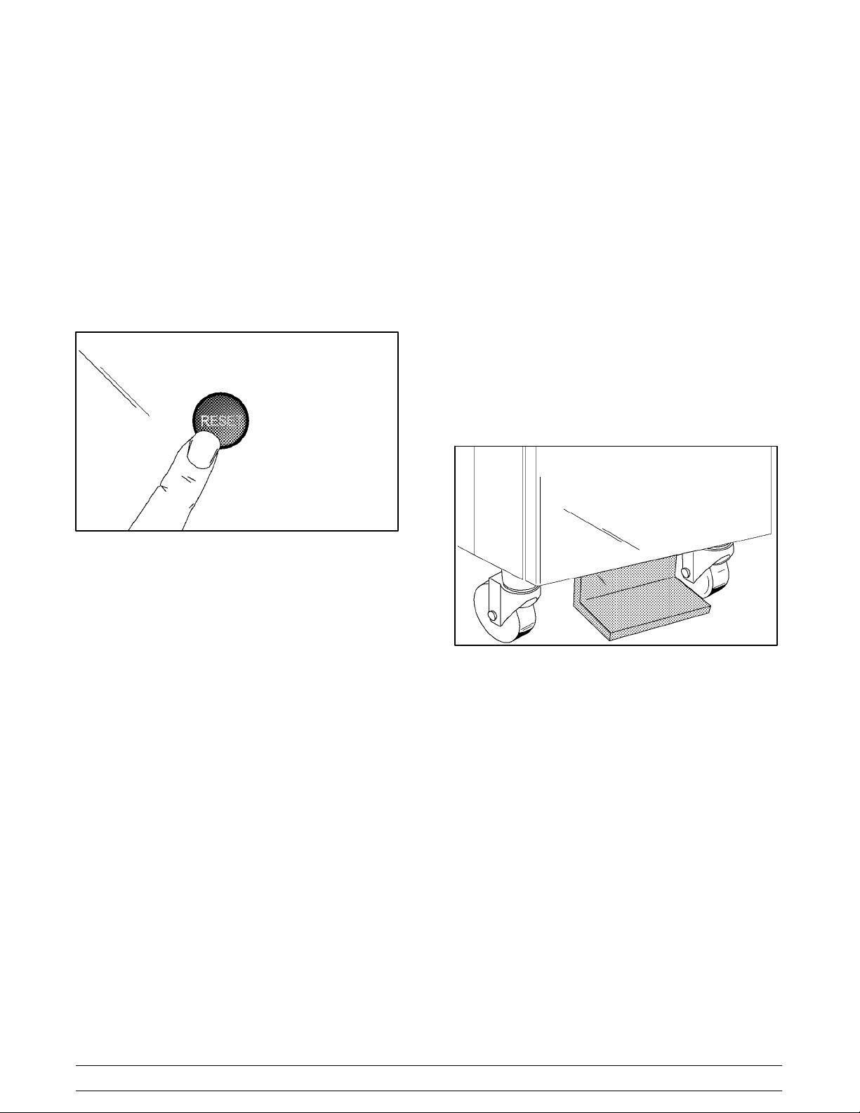
Reset Mechanism
Auto Lift Switch (Model 60 Only)*
The reset protects the beater motor from an overload
condition. If an overload occurs, the reset mechanism
will trip. To properly reset the freezer, set the control
switch to “OFF”. Lift up the right upper side panel and
press the reset button firmly. Turn the control switch to
“WASH” and observe the freezer’s performance.
Return the control switch to the “AUTO” position to
resume normal operation.
If the reset mechanism should trip again, contact your
authorized Taylor Distributor to resolve the problem.
Figure 1
The auto lift switch is located below the flavor selector
switch. To draw product, the auto lift switch may be
used. Press the switch. Just before the desired level
in the cup is reached, release the switch. The draw arm
will lower the draw valve and the product will stop
flowing.
Foot Pedal (Model 60 Only)
The foot pedal is located on the lower front of the
machine. To draw product from the Model 60, the foot
pedal may be used. Press the foot pedal. Just before
the desired level in the cup is reached, release the foot
pedal. The draw arm will lower the draw valve and the
product will stop flowing.
Consistency Control*
The viscosity (thickness) of the shake is controlled by
a sensing device called the consistency control. The
consistency control switch is located below the control
switch. To achieve a thicker shake, turn the knob
clockwise and counterclockwise to achieve a thinner
shake consistency.
Allow the refrigeration system to cycle on and off two
or three times before an accurate consistency can be
evaluated.
Spinner Rinse Switch*
The spinner rinse switch is located next to the
consistency control knob. To clean the spinner housing
from syrup residue:
1. Place the control switch in the “AUTO” position.
2. Hold a cup under the spinner housing.
3. Press the spinner rinse switch. Water will flow
until the switch is released.
4. Release the switch when the housing has been
thoroughly rinsed.
Figure 2
Flavor Selector Switch*
The flavor selector switch consists of four flavor
buttons. The left button controls the No. 1 tank and its
lines. The second button from the left controls the No.
2 tank and its lines. The third button from the left
controls the No. 3 tank and its lines. The right selector
button (“Van”) is the “OFF” button and may be used to
dispense the unflavored product as a vanilla shake.
*See illustration, page 8.
Models 60 & 62 Important: To the Operator
9
Section 6 Operating Procedures
The Models 60 and 62 have one, 7 quart (6.6 liter)
freezing cylinder. These totally automatic freezers
offer four separate flavors. Each flavor is blended and
ejected from the same spout. (Use only single strength
syrup that is free of pulp and seeds.)
We begin our instructions at the point where we enter
the store in the morning and find the parts
disassembled and laid out to air dry from the previous
night’s brush cleaning.
These opening procedures will show you how to
assemble these parts into the freezer, sanitize them,
and prime the freezer with fresh mix in preparation to
serve your first shake.
Figure 3
groove until it snaps into place. DO NOT lubricate the
hex end of the drive shaft. Fill the inside portion of the
seal with 1/4” more lubricant. Lubricate the flat side of
the seal that comes in contact with the bearing.
Note: Make sure seal is not installed inside-out. The
ridge that protrudes in the center of the seal should be
on the outside.
Figure 4
Insert the drive shaft into the freezing cylinder, hex end
first, and into the rear shell bearing until the seal fits
securely over the rear shell bearing. Be certain the
drive shaft fits into the drive coupling without binding.
If you are disassembling the machine for the first time
or need information to get to this starting point in our
instructions, turn to page 22 “Disassembly”, and start
there.
Assembly
Note: When lubricating parts, use an approved food
grade lubricant (example: Taylor Lube).
MAKESURE THE CONTROL SWITCH IS IN
THE “OFF” POSITION.
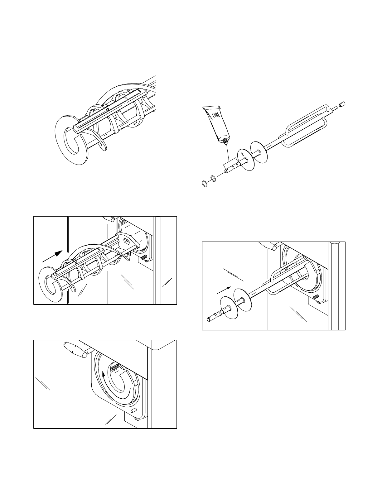
Step 1
Install the drive shaft. Lubricate the groove and shaft
portion that comes in contact with the bearing on the
beater drive shaft. Slide the seal over the shaft and the
Figure 5
Step 2
Install the beater assembly. First check scraper blades
for any nicks or signs of wear. If any nicks are present
or if the blade is worn, replace both blades.
Note: Both scraper blades should be replaced every
three months.
10
Models 60 & 62Operating Procedures
If the blades are in good condition, assemble the blade
and the clip. Place the rear scraper blade over the two
rear holding pins (knife edge to the outside).
Figure 6
Holding the rear blade on the beater, slide it halfway
into the freezing cylinder.Install the front scraper blade
and the scraper blade clip over the front holding pins.
Slide the beater assembly the rest of the way into the
freezing cylinder.
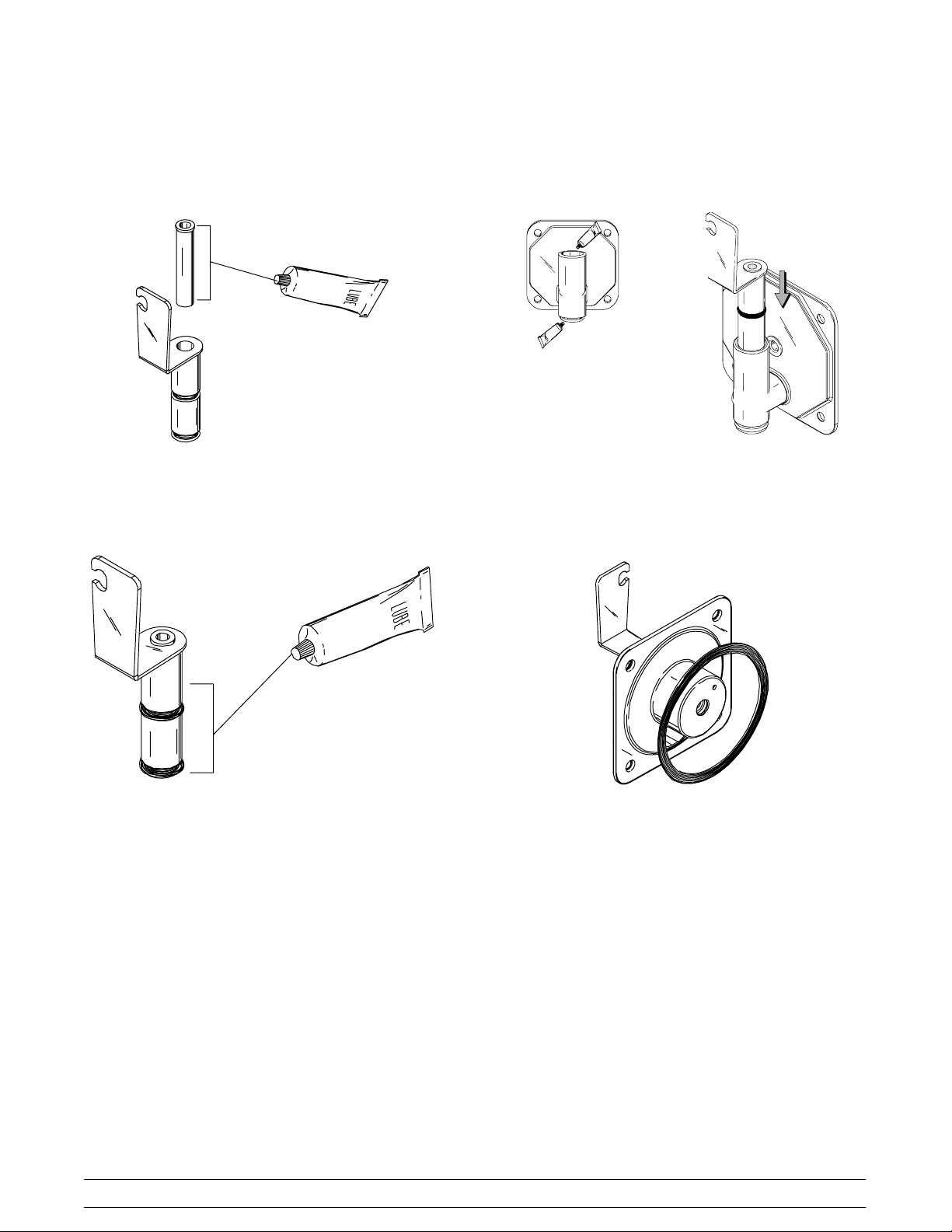
Step 3
Install the torque rotor assembly. Assemble the torque
rotor by sliding the two o-rings on the front of the shaft
and lubricate them thoroughly to prevent leaking.
Place the white plastic guide bearing on the rear of the
rotor shaft. DO NOT lubricate the plastic guide bearing
Figure 9
Insert the torque rotor, plastic guide bearing end first,
making sure that it fits into the hole in the beater drive
shaft. Rotate it several times to check for proper
positioning.
Figure 7
Make sure the beater assembly is in position over the
drive shaft. Turn the beater slightly to be certain that
the beater assembly is properly seated.
Figure 8
Models 60 & 62 Operating Procedures
11
Figure 10
Step 4
Install the draw valve. Lubricate the plastic spinner
bearing. Insert the plastic spinner bearing into the top
of the draw valve.
Figure 11
Slide the two o-rings onto the draw valve and lubricate
the draw valve.
Lubricate the inside of the door spout, top and bottom.
Insert the draw valve into the freezer door from the top.
It will be necessary to rotate the draw valve to the right
when assembling the door to the freezer.
Figure 13
Step 5
Install the freezer door. Place the large rubber gasket
into the groove on the back side of the freezer door.DO
NOT lubricate the gasket.
Figure 12
12
Figure 14
Models 60 & 62Operating Procedures
 Loading...