

Taylor Freezer 383, 384 Operation Manual

Models 383 & 384
Slush Freezers
Operating Instructions
053083--M
10/98

Complete this page for quick reference when service is required:
r
Taylor Distributor:
Address:
Phone:
Service:
Parts:
Date of Installation:
Information found on the data label:
Model Number:
Serial Number:
Electrical Specs: Voltage Cycle
Phase
Maximum Fuse Size: A
Minimum Wire Ampacity: A
E October, 1998 Taylo
All rights reserved.
053083-M
Taylor Company
The word Taylor and the Crown design
are registered trademarks in the United States
of America and certain other countries.
a division of Carrier Commercial Refrigeration, Inc.
750 N. Blackhawk Blvd.
Rockton, IL 61072

Table of Contents
Section 1 To the Installer 1............................................
Electrical Connections 1.................................................
Section 2 To the Operator 2...........................................
Compressor Warranty Disclaimer 2.......................................
Section 3 Safety 3....................................................
Section 4 Operator Parts Identification 4...............................
Beater Door Assembly 5.................................................
Accessories 6..........................................................
Section 5 Important: To the Operator 7.................................
Symbol Legend 7.......................................................
Control Switch (Item 1) 7.................................................
Fill Switch (Item 2) 8....................................................
Add Mix Light (Item 3) 8.................................................
Mix Out Light (Item 4) 8..................................................
Viscosity Control (Item 5) 8...............................................
Standby Switch (Optional) 8..............................................
Display Light Switch (Item 6) (Optional) 8..................................
Push-Button Switch 8....................................................
Section 6 Operating Procedures 9.....................................
Assembly 9............................................................
Sanitizing 13............................................................
Priming 14..............................................................
Closing Procedure 14....................................................
Rinsing 14..............................................................
Cleaning 15.............................................................
Disassembly 16..........................................................
Brush Cleaning 16.......................................................
Section 7 Important: Operator Checklist 17..............................
During Cleaning and Sanitizing 17.........................................
Troubleshooting Bacterial Count 17........................................
Regular Maintenance Checks 17...........................................
Winter Storage 17........................................................
Section 8 Troubleshooting Guide 18....................................
Section 9 Parts Replacement Schedule 21...............................
Section 10 Parts List 22.................................................
Wiring Diagrams 28......................................................
Note: Continuing research results in steady improvements; therefore,information
in this manual is subject to change without notice.
Models 383 & 384 Table of Contents

Notes:
Table of Contents Models 383 & 384

Section 1 To the Installer
This machine is designed for indoor use only.
CAUTION: THIS EQUIPMENT MUST BE
DO NOT installthemachineinanarea
where a water jet could be used to clean or rinse the
machine. Failure to follow this instruction may result
in serious electrical shock.
PROPERLY GROUNDED! FAILURE TO DO SO
CAN RESULT IN SEVERE PERSONAL INJURY
FROM ELECTRICAL SHOCK!
Electrical Connections
Each freezer requires one power supply for each
data label. Check the data label on the freezer for
fuse, circuit ampacity and electrical specifications.
Refer to the wiring diagram provided inside of the
electrical box, for proper power connections.
In the United States, this equipment is intended to
be installed in accordance with the National
Electrical Code (NEC), ANSI/NFPA 70-1987. The
purpose of the NEC code is the practical
safeguarding of persons and property from hazards
arising from the use of electricity. This code contains
provisions considered necessary for safety.
Compliance therewith and proper maintenance will
result in an installation essentially free from hazard!
In all other areas of the world, equipment should be
installed in accordance with the existing local codes.
Please contact your local authorities.
Stationary appliances which are not equipped with a
power cord and a plug or other device to disconnect
the appliance from the power source must have an
all-pole disconnecting device with a contact gap of at
least 3 mm installed in the external installation.
Beater rotation must be counterclockwise as
viewed looking into the freezing cylinder of the
Model 383/384 dispenser.
To correct rotation on a three-phase unit, exchange
any two incoming power supply lines at the freezer
main terminal block only.
To correct rotation on a single-phase unit, exchange
the leads inside the beater motor. (Follow the
diagram printed on the motor.)
Electrical connections are made directly to the splice
box. The splice box is located behind the back
panel.
IMPORTANT!
Beater rotation on the 380 Series
differs from other Taylor equipment.
040323
Models 383 & 384 To the Installer
1

Section 2 To the Operator
The slush freezer you have purchased has been
carefully engineered and manufactured to give you
dependable operation. The Taylor equipment, when
properly operated and cared for, will produce a
consistent quality product. Like all mechanical
products, this machine will require cleaning and
maintenance. A minimum amount of care and
attention is necessary if the operating procedures
outlined in this manual are followed closely.
This Operator’s Manual should be read before
operating or performing any maintenance on your
equipment.
Your 380 Series model will NOT eventually
compensate and correct for any errors during the
set-up or filling operations. Thus, the initial assembly
and priming procedures are of extreme importance.
It is strongly recommended that all personnel
responsible for the equipment’s operation thoroughly
read this manual.
If you require technical assistance, please contact
your local authorized Taylor Distributor.
If the crossed out wheeled bin symbol is
affixed to this product, it signifies that this product is
compliant with the EU Directive as well as other
similar legislation in effect after August 13, 2005.
Therefore, it must be collected separately after its
use is completed, and cannot be disposed as
unsorted municipal waste.
The user is responsible for returning the product to
the appropriate collection facility, as specified by
your local code.
For additional information regarding applicable local
laws, please contact the municipal facility and/or
local distributor.
Compressor Warranty Disclaimer
The refrigeration compressor(s) on this machine are
warranted for the term indicated on the warranty
card accompanying this machine. However, due to
the Montreal Protocol and the U.S. Clean Air Act
Amendments of 1990, many new refrigerants are
being tested and developed, thus seeking their way
into the service industry. Some of these new
refrigerants are being advertised as drop-in
replacements for numerous applications. It should
be noted that, in the event of ordinary service to this
machine’s refrigeration system, only the refrigerant
specified on the affixed data label should be
used. The unauthorized use of alternate refrigerants
will void your compressor warranty. It will be the
owner’s responsibility to make this fact known to any
technician he employs.
It should also be noted that Taylor does not warrant
the refrigerant used in its equipment. For example, if
the refrigerant is lost during the course of ordinary
service to this machine, Taylor has no obligation to
either supply or provide its replacement either at
billable or unbillable terms. Taylor does have the
obligation to recommend a suitable replacement if
the original refrigerant is banned, obsoleted, or no
longer available during the five year warranty of the
compressor.
Taylor will continue to monitor the industry and test
new alternates as they are being developed. Should
a new alternate prove, through our testing, that it
would be accepted as a drop-in replacement, then
the above disclaimer would become null and void.
To find out the current status of an alternate
refrigerant as it relates to your compressor warranty,
call the local Taylor Distributor or the Taylor Factory.
Be prepared to provide the Model/Serial Number of
the unit in question.
070123
2
Models 383 & 384To the Operator

Section 3 Safety
We at Taylor are concerned about the safety of the
operator when he or she comes in contact with the
freezer and its parts. Taylor has gone to extreme
efforts to design and manufacture built-in safety
features to protect both you and the service
technician. As an example, warning labels have
been attached to the freezer to further point out
safety precautions to the operator.
IMPORTANT - Failure to adhere to the
following safety precautions may result in
severe personal injury. Failure to comply with
these warnings may damage the machine and
its components. Component damage will result
in part replacement expense and service repair
expense.
To Operate Safely:
S DO NOT allow untrained personnel to
operate this machine.
S DO NOT operate the freezer unless all
service panels and access doors are
restrained with screws.
S DO NOT put objects or fingers in door
spout.
S DO NOT remove the door, beater, scraper
blades, drive shaft or torque rotor shaft
unless the power switch is in the “OFF”
position.
Failure to follow these instructions may result in
contaminated product or personal injury from
hazardous moving parts.
DO NOT operate the freezer without
reading this operator’s manual. Failure to follow this
instruction may result in equipment damage, poor
freezer performance, health hazards, or personal
injury.
S DO NOT operate the freezer unless it is
properly grounded.
S DO NOT attempt any repairs unless the
main power supply to the freezer has been
disconnected.
S DO NOT operate the freezer with larger
fuses than specified on the freezer data
label.
Failure to follow these instructions may result in
electrocution. Contact your local authorized Taylor
Distributor for service.
DO NOT use a water jet to clean or rinse
the freezer. Failure to follow this instruction may
result in serious electrical shock.
USE EXTREME CAUTION when removing
the beater assembly. The scraper blades are very
sharp and may cause injury.
This freezer must be placed on a level
surface. Failure to comply may result in personal
injury or equipment damage.
DO NOT obstruct air intake and discharge openings:
6” (152 mm) minimum air space on all sides. Failure
to follow this instruction may cause poor freezer
performance and damage to the machine.
This freezer is designed to operate indoors, under
normal ambient temperatures of 70°- 75°F
(21°- 24°C). The freezer has successfully performed
in high ambient temperatures of 104°F (40°C) at
reduced capacities.
NOISE LEVEL: Airborne noise emission does not
exceed 78 dB(A) when measured at a distance of
1.0 meter from the surface of the machine and at a
height of 1.6 meters from the floor.
070123
Models 383 & 384 Safety
3
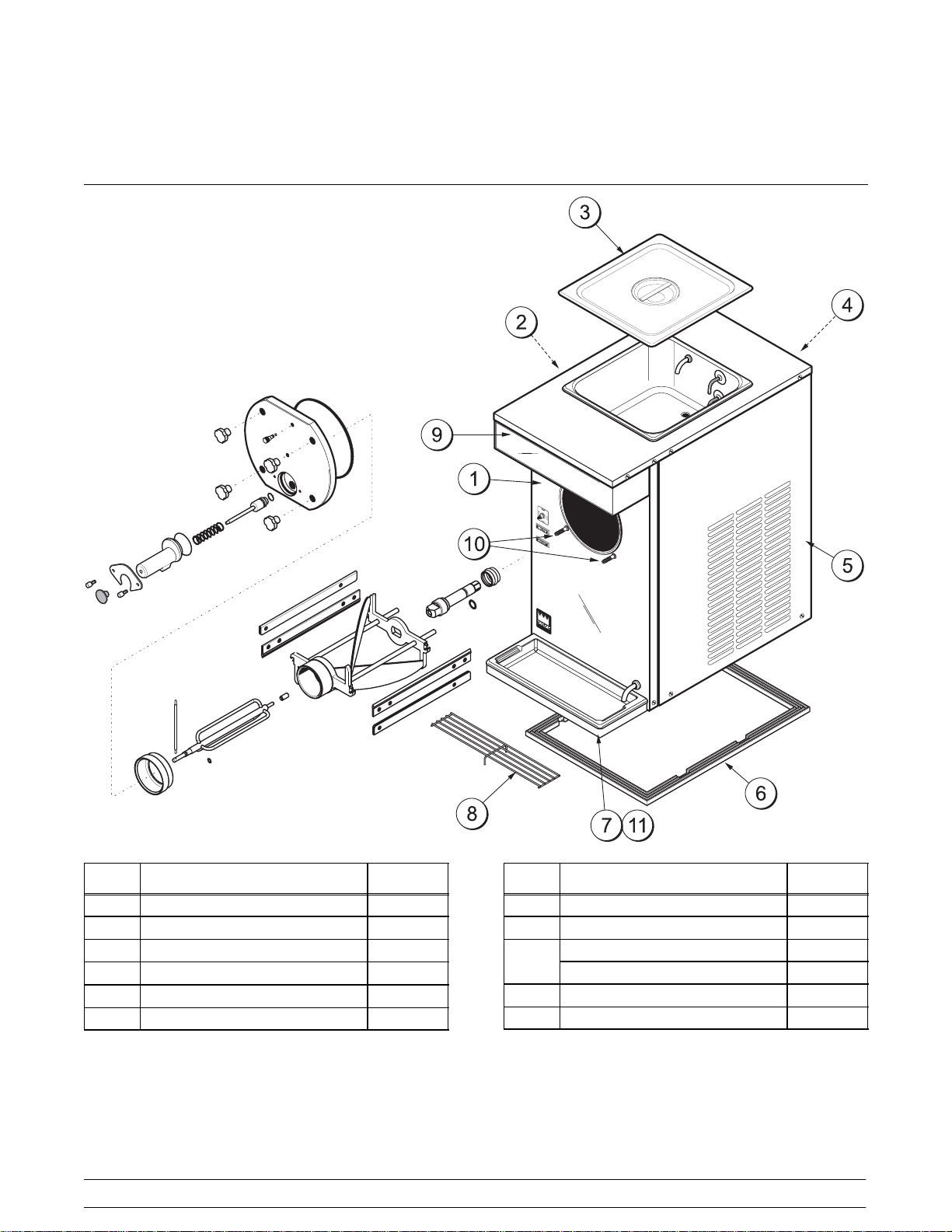
Section 4 Operator Parts Identification
ITEM DESCRIPTION PART NO.
1 PANEL-FRONT 051090
2 PANEL-SIDE LEFT 052117
3 COVER-HOPPER 12 QT 045416
4 PANEL A.-REAR X52116
5 PANEL-SIDE RIGHT 051713
6 GASKET-BASE PAN 051868
ITEM DESCRIPTION PART NO.
7 TRAY A.-DRIP X46848
8 SHIELD-SPLASH 046851
DECAL-DEC-FLAVOR - 4 050703
9
DECAL-DEC-TAYLOR 045967
10 STUD-FREEZER DOOR 051950
11 SHELF-DRIP TRAY 052065
4
Models 383 & 384Operator Parts Identification

Beater Door Assembly
ITEM DESCRIPTION PART NO.
1 KNOB-DRAW VALVE-BLACK 047358
2 SCREW-1/4-20X9/16 THUMB 047632
3 PLATE-DRAW SPOUT MOUNT 049275
4 SPOUT-DOOR ZERO WASTE 049276-BLA
5 O-RING-2.375 OD X 1/16W 046830
6 SPRING-COMP.845X.055X3.5 047357
7 VALVE-DRAW 047353
8 NUT-STUD 045644
9 O-RING-7/8 OD X .103W 014402
10 DOOR A.-PARTIAL X51098
11 O-RING-8-3/8 ODX.105W 027814
12 BEARING-FRONT-TORQUE 052005
Models 383 & 384 Operator Parts Identification
ITEM DESCRIPTION PART NO.
13 ARM-TORQUE 014500
14 O-RING-.291 ID X .080W 018550
15 TORQUE A. X51081
16 BEARING-GUIDE 014496
17 BEATER A.-TORQUE X51105
18 BLADE-SCRAPER 051088
19 CLIP-SCRAPER BLADE 051978
20 SHAFT-BEATER 049270
21 O-RING-7/8 OD X .139W 025307
22 SEAL-DRIVE SHAFT 032560
23 PLUG-PRIME *380/1* 046833
24 O-RING-9/32 OD X 1/16 WALL 029751
5
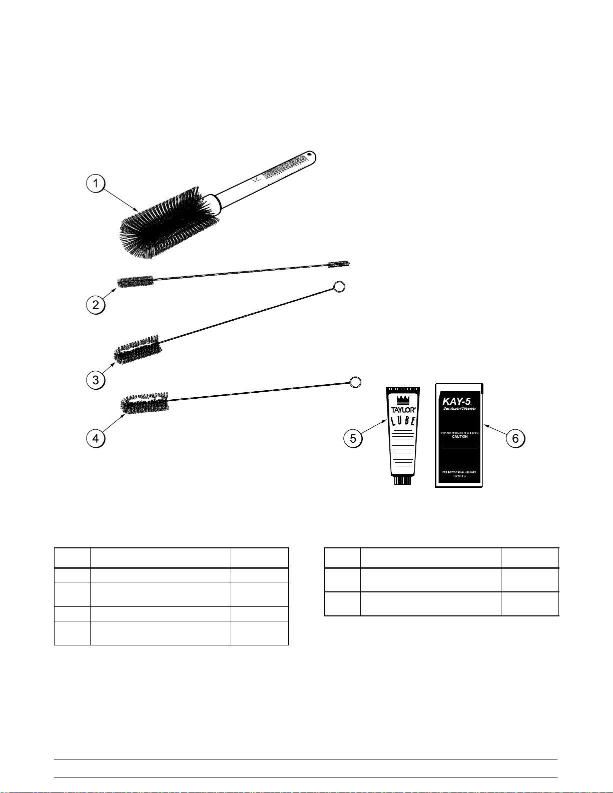
Accessories
ITEM DESCRIPTION PART NO.
1 BRUSH-MIX PUMP BODY-3”X7” 023316
2 BRUSH-DRAW VALVE
1”X2”X17”
3 BRUSH-DOUBLE ENDED 013072
4 BRUSH-REAR BRG
1IN.DX2IN.L
013073
013071
ITEM DESCRIPTION PART NO.
5 LUBRICANT-TAYLOR HI
PERF-4
6 SANITIZER KAY-5 (CASE OF
125 PACKETS
6
Models 383 & 384Operator Parts Identification
048232
041082
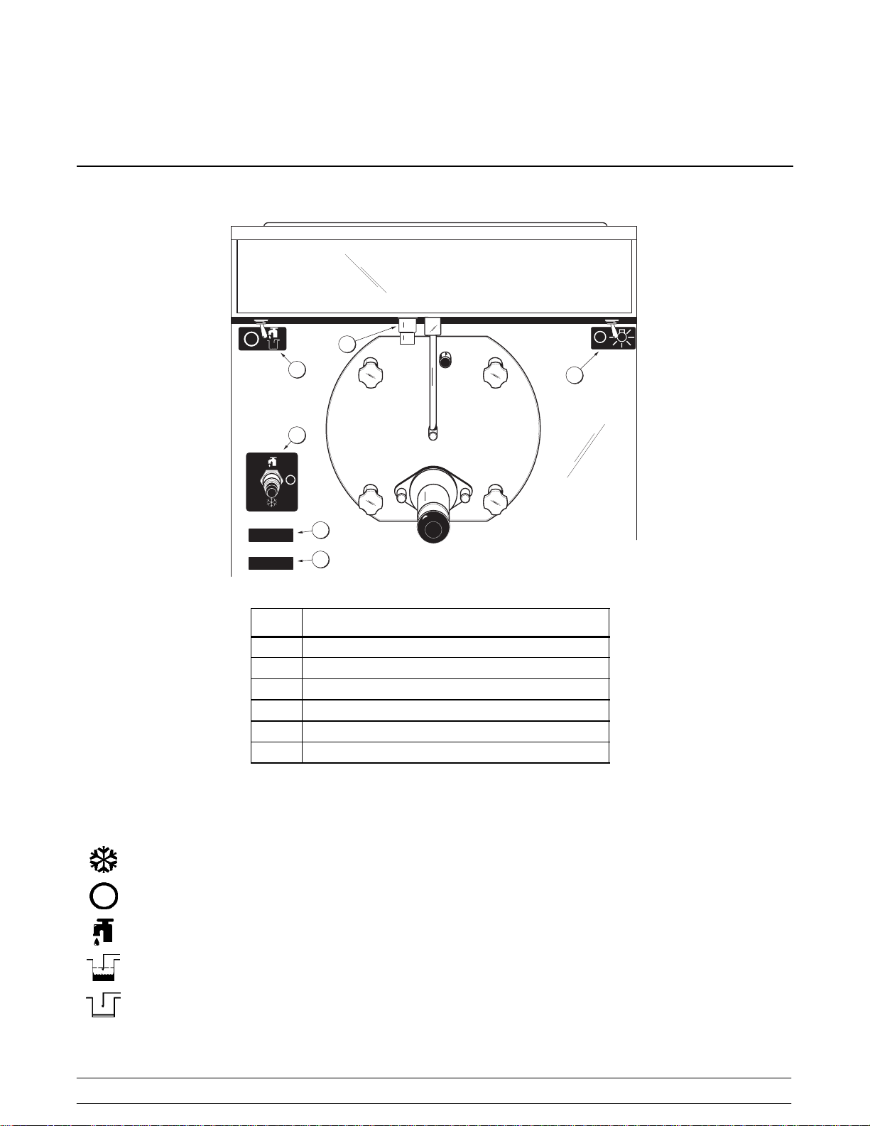
Section 5 Important: To the Operator
5
2
1
ADD MIX
MIX OUT
ITEM DESCRIPTION
3
4
1 Control Switch
2 Fill Switch
3 Add Mix Light
4 Mix Out Light
5 Viscosity Control
6 Display Light Switch
6
Symbol Legend
= The “ON/AUTO” symbol.
Control Switch (Item 1)
The control switch is located on the front of the
machine. The center position is “OFF”. The “UP”
position is the “WASH” mode and activates the
= The “OFF” symbol.
beater motor only. The “DOWN” position is the
“AUTO” mode. The “AUTO” mode activates the
= The “WASH” symbol.
beater motor and enables refrigeration when the fill
switch is in the “ON” position.
= The “ADD MIX” symbol.
= The “MIX OUT” symbol.
Models 383 & 384 Important: To the Operator
7
 Loading...