

Taylor Freezer 340, 341, 342 Operation Manual

Models 340, 341, 342
Slush Freezers
Operating Instructions
028764−M
1/97

Complete this page for quick reference when service is required:
Taylor Distributor:
Address:
Phone:
Service:
Parts:
Date of Installation:
Information found on the data label:
Model Number:
Serial Number:
Electrical Specs: Voltage Cycle
Phase
Maximum Fuse Size: A
Minimum Wire Ampacity: A
E January, 1997 Taylor
All rights reserved.
028764−M
Taylor Company
The word Taylor and the Crown design
are registered trademarks in the United States
of America and certain other countries.
a division of Carrier Commercial Refrigeration, Inc.
750 N. Blackhawk Blvd.
Rockton, IL 61072

Table of Contents
______________________________________________________________________________
Section 1 To the Installer 1. . . . . . . . . . . . . . . . . . . . . . . . . . . . . . . . . . . . . . . . . . . .
Water Connections (Water Cooled Units Only) 1. . . . . . . . . . . . . . . . . . . . . . . . . . . .
Air Cooled Units 1. . . . . . . . . . . . . . . . . . . . . . . . . . . . . . . . . . . . . . . . . . . . . . . . . . . . . . .
Electrical Connections 1. . . . . . . . . . . . . . . . . . . . . . . . . . . . . . . . . . . . . . . . . . . . . . . . .
Section 2 To the Operator 3. . . . . . . . . . . . . . . . . . . . . . . . . . . . . . . . . . . . . . . . . . .
Compressor Warranty Disclaimer 3. . . . . . . . . . . . . . . . . . . . . . . . . . . . . . . . . . . . . . .
Section 3 Safety 4. . . . . . . . . . . . . . . . . . . . . . . . . . . . . . . . . . . . . . . . . . . . . . . . . . . .
Section 4 Operator Parts Identification 5. . . . . . . . . . . . . . . . . . . . . . . . . . . . . . .
Section 5 Important: To the Operator 10. . . . . . . . . . . . . . . . . . . . . . . . . . . . . . . . .
Symbol Definitions 10. . . . . . . . . . . . . . . . . . . . . . . . . . . . . . . . . . . . . . . . . . . . . . . . . . . .
Control Switch 10. . . . . . . . . . . . . . . . . . . . . . . . . . . . . . . . . . . . . . . . . . . . . . . . . . . . . . . .
Consistency Control 10. . . . . . . . . . . . . . . . . . . . . . . . . . . . . . . . . . . . . . . . . . . . . . . . . . .
Indicator Light - “Add Mix” 10. . . . . . . . . . . . . . . . . . . . . . . . . . . . . . . . . . . . . . . . . . . . . .
For Your Information 10. . . . . . . . . . . . . . . . . . . . . . . . . . . . . . . . . . . . . . . . . . . . . . . . . . .
Section 6 Operating Procedures 11. . . . . . . . . . . . . . . . . . . . . . . . . . . . . . . . . . . . .
Assembly 11. . . . . . . . . . . . . . . . . . . . . . . . . . . . . . . . . . . . . . . . . . . . . . . . . . . . . . . . . . . .
Sanitizing 15. . . . . . . . . . . . . . . . . . . . . . . . . . . . . . . . . . . . . . . . . . . . . . . . . . . . . . . . . . . .
Priming 16. . . . . . . . . . . . . . . . . . . . . . . . . . . . . . . . . . . . . . . . . . . . . . . . . . . . . . . . . . . . . .
Closing Procedure 17. . . . . . . . . . . . . . . . . . . . . . . . . . . . . . . . . . . . . . . . . . . . . . . . . . . .
Draining Product From the Freezing Cylinder 18. . . . . . . . . . . . . . . . . . . . . . . . . . . . .
Rinsing 18. . . . . . . . . . . . . . . . . . . . . . . . . . . . . . . . . . . . . . . . . . . . . . . . . . . . . . . . . . . . . .
Cleaning 19. . . . . . . . . . . . . . . . . . . . . . . . . . . . . . . . . . . . . . . . . . . . . . . . . . . . . . . . . . . . .
Disassembly 20. . . . . . . . . . . . . . . . . . . . . . . . . . . . . . . . . . . . . . . . . . . . . . . . . . . . . . . . . .
Brush Cleaning 20. . . . . . . . . . . . . . . . . . . . . . . . . . . . . . . . . . . . . . . . . . . . . . . . . . . . . . .
Models 340, 341, 342
Table of Contents

Table of Contents -- Page 2
______________________________________________________________________________
Section 7 Important: Operator Checklist 21..............................
During Cleaning and Sanitizing 21.........................................
Troubleshooting Bacterial Count 21........................................
Regular Maintenance Checks 21...........................................
Winter Storage 22........................................................
Section 8 Troubleshooting Guide 23....................................
Section 9 Part s Replacement Schedule 26...............................
Section 10 Parts List 27.................................................
Wiring Diagrams 37......................................................
Note: Continuing research results in steady improvements; therefore, information
in this manual is subject to change without notice.
E January, 1997 Taylor
All rights reserved.
028764--M
Taylor Company
The word T aylor and the Crown design
are registered trademarks in the United States
of America and certain other countries.
a division of Carrier Commercial Refrigeration, Inc.
750 N. Blackhawk Blvd.
Rockton, IL 61072
Table of Contents Models 340, 341, 342

Section 1 To the Installer
This machine is designed for indoor use only.
DO NOT install the machine in an area where
a water jet could be used to clean or rinse the machine.
Failure to follow this instruction may result in serious
electrical shock.
Water Connections
(Water Cooled Units Only)
An adequate cold water supply with a hand shut-off
valve must be provided. On the underside of the base
pan, two 3/8” I.P.S. (for single-head units) or two 1/2”
I.P.S. (for double-head units) water connections for
inlet and outlet have been provided for easy hook-up.
1/2” inside diameter water lines should be connected
to the machine. (Flexible lines are recommended, if
local codes permit.) Depending on local water
conditions, it may be advisable to install a water
strainer to prevent foreign substances from clogging
the automatic water valve. There will be only one water
“in” and one water “out” connection for both
double-head and single-head units. DO NOT install a
hand shut-off valve on the water “out” line! Water
should always flow in this order: first, through the
automatic water valve; second, through the
condenser; and third, through the outlet fitting to an
open trap drain.
Electrical Connections
Each freezer requires one power supply for each data
label. Check the data label(s) on the freezer for fuse,
circuit ampacity and electrical specifications. For
proper power connections, refer to the wiring diagram
provided inside of the electrical box.
In the United States, this equipment is intended to be
installed in accordance with the National Electrical
Code (NEC), ANSI/NFPA 70−1987. The purpose of
the NEC code is the practical safeguarding of persons
and property from hazards arising from the use of
electricity. This code contains provisions considered
necessary for safety. Compliance therewith and
proper maintenance will result in an installation
essentially free from hazard!
In all other areas of the world, equipment should be
installed in accordance with the existing local codes.
Please contact your local authorities.
Stationary appliances which are not equipped with a
power cord and a plug or other device to disconnect
the appliance from the power source must have an
all−pole disconnecting device with a contact gap of at
least 3 mm installed in the external installation.
Air Cooled Units
This equipment is provided with a grounding lug
The model 340 air cooled unit requires a minimum of
6” (152 mm) of clearance around both sides of the
freezer. It is recommended to install a skirt to one side
of the unit, and to place the back of the unit against a
wall. The models 341 and 342 air cooled units require
a minimum of 3” (76 mm) of air clearance around all
sides.
Failure to allow adequate clearance can reduce the
refrigeration capacity of the freezer and possibly
cause permanent damage to the compressor.
Models 340, 341, 342 To the Installer
that is to be properly attached to the rear of the frame
by the authorized installer. The installation location is
marked by the equipotential bonding symbol (5021 of
IEC 60417−1) on the removable panel and the frame.
CAUTION: THIS EQUIPMENT MUST BE
PROPERLY GROUNDED! FAILURE TO DO SO
CAN RESULT IN SEVERE PERSONAL INJURY
FROM ELECTRICAL SHOCK!
080213
1
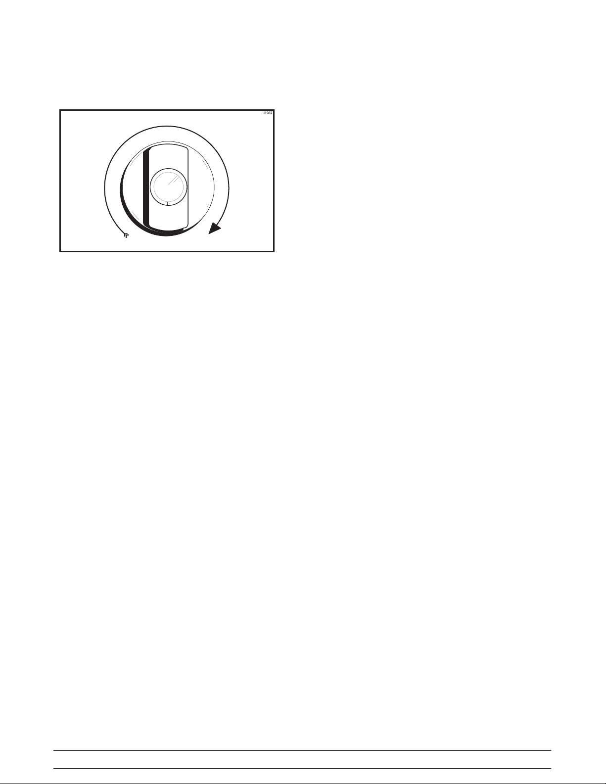
Beater rotation must be clockwise as viewed looking
into the freezing cylinder.
Figure 1
Note: The following procedures should be performed
by a trained service technician.
To correct rotation on a three-phase unit, interchange
any two incoming power supply lines at the freezer
main terminal block only.
To correct rotation on a single-phase unit, change the
leads inside the beater motor. (Follow the diagram
printed on the motor.)
Electrical connections are made directly to the
terminal block. The terminal block is provided in the
main control box located under the upper left side
panel on counter models or behind the service panel
on console models.
2
Models 340, 341, 342To the Installer

Section 2 To the Operator
The freezer you have purchased has been carefully
engineered and manufactured to provide dependable
operation. The Taylor Slush Models 340, 341, and 342,
when properly operated and cared for, will produce a
consistent quality product. Like all mechanical
products, these machines will require cleaning and
maintenance. A minimum amount of care and
attention is necessary if the operating procedures
outlined in this manual are followed closely.
This Operator’s Manual should be read before
operating or performing any maintenance on your
equipment.
Your Taylor freezer will NOT eventually compensate
and correct for any errors during the set-up or filling
operations. Thus, the initial assembly and priming
procedures are of extreme importance. It is strongly
recommended that personnel responsible for the
equipment’s operation study these procedures
together in order to be properly trained and to make
sure that no misunderstandings exist.
In the event you should require technical assistance,
please contact your local authorized Taylor Distributor.
If the crossed out wheeled bin symbol is
affixed to this product, it signifies that this product is
compliant with the EU Directive as well as other similar
legislation in effect after August 13, 2005. Therefore,
it must be collected separately after its use is
completed, and cannot be disposed as unsorted
municipal waste.
The user is responsible for returning the product to the
appropriate collection facility, as specified by your local
code.
For additional information regarding applicable local
laws, please contact the municipal facility and/or local
distributor.
Compressor Warranty Disclaimer
The refrigeration compressor(s) on this machine are
warranted for the term indicated on the warranty card
accompanying this machine. However, due to the
Montreal Protocol and the U.S. Clean Air Act
Amendments of 1990, many new refrigerants are
being tested and developed, thus seeking their way
into the service industry. Some of these new
refrigerants are being advertised as drop-in
replacements for numerous applications. It should be
noted that, in the event of ordinary service to this
machine’s refrigeration system, only the refrigerant
specified on the affixed data label should be used.
The unauthorized use of alternate refrigerants will void
your compressor warranty. It will be the owner’s
responsibility to make this fact known to any technician
he employs.
It should also be noted that Taylor does not warrant the
refrigerant used in its equipment. For example, if the
refrigerant is lost during the course of ordinary service
to this machine, Taylor has no obligation to either
supply or provide its replacement either at billable or
unbillable terms. Taylor does have the obligation to
recommend a suitable replacement if the original
refrigerant is banned, obsoleted, or no longer available
during the five year warranty of the compressor.
Taylor will continue to monitor the industry and test
new alternates as they are being developed. Should a
new alternate prove, through our testing, that it would
be accepted as a drop-in replacement, then the above
disclaimer would become null and void. To find out the
current status of an alternate refrigerant as it relates to
your compressor warranty, call the local Taylor
Distributor or the Taylor Factory. Be prepared to
provide the Model/Serial Number of the unit in
question.
061211
Models 340, 341, 342 To the Operator
3
Section 3 Safety
We at Taylor are concerned about the safety of the
operator when he or she comes in contact with the
freezer and its parts. Taylor has gone to extreme
efforts to design and manufacture built-in safety
features to protect both you and the service technician.
As an example, warning labels have been attached to
the freezer to further point out safety precautions to the
operator.
IMPORTANT − Failure to adhere to the
following safety precautions may result in severe
personal injury. Failure to comply with these
warnings may damage the machine and its
components. Component damage will result in
part replacement expense and service repair
expense.
S DO NOT allow untrained personnel to
operate this machine.
S DO NOT operate the freezer unless all
service panels and access doors are
restrained with screws.
S DO NOT remove the door, beater, scraper
blades, drive shaft, or torque rotor shaft
unless all control switches are in the OFF
position.
S DO NOT put objects or fingers in the door
spout.
Failure to follow these instructions may result in
contaminated product or severe personal injury to
fingers or hands from hazardous moving parts.
To Operate Safely:
DO NOT operate the freezer without reading
this operator’s manual. Failure to follow this instruction
may result in equipment damage, poor freezer
performance, health hazards, or personal injury.
S DO NOT operate the freezer unless it is
properly grounded.
S DO NOT attempt any repairs unless the
main power supply to the freezer has been
disconnected.
S DO NOT operate the freezer with larger
fuses than specified on the freezer data
label.
Failure to follow these instructions may result in
electrocution or damage to the machine. Contact your
local authorized Taylor Distributor for service.
USE EXTREME CAUTION when removing
the beater assembly. The scraper blades are very
sharp and may cause injury.
These freezers must be placed on a level
surface. Failure to comply may result in personal injury
or equipment damage.
DO NOT obstruct air intake and discharge openings:
Models 341/342: 3” (76 mm) minimum air space on all
sides.
Model 340: 6” (152 mm) minimum air space on sides
and 0” at the rear. It is recommended to install a skirt
to one side of the unit, and to place the back of the unit
against a wall.
Failure to follow this instruction may cause poor
freezer performance and damage to the machine.
These freezers are designed to operate indoors, under
normal ambient temperatures of 70_−75_F
(21_−24_C). The freezers have successfully
performed in high ambient temperatures of 104_F
(40_C) at reduced capacities.
DO NOT use a water jet to clean or rinse the
freezer. Failure to follow this instruction may result in
serious electrical shock.
061211
NOISE LEVEL: Airborne noise emission does not
exceed 78 dB(A) when measured at a distance of 1.0
meter from the surface of the machine and at a height
of 1.6 meters from the floor.
4
Models 340, 341, 342Safety
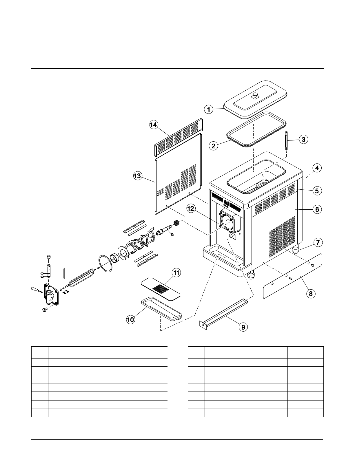
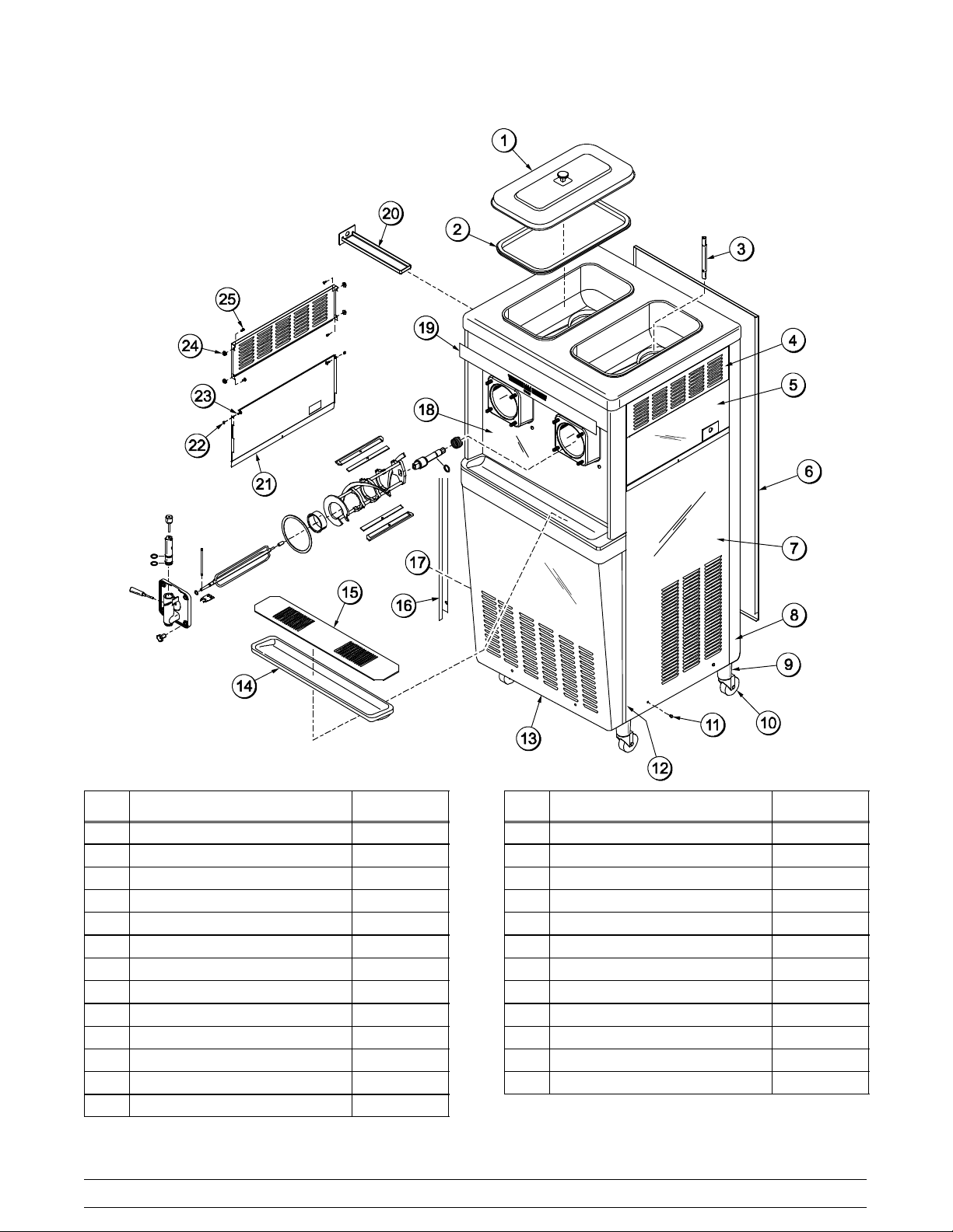
Section 4 Operator Parts Identification
Model 340
Item Description Part No.
1 Cover A.-Hopper X38458
2 Gasket-Hopper Cover 038375
3 Tube-Feed 015176-9
4 Panel-Rear 047008
5 Louver-Side Top 051192
6 Panel-Right Side 047007
7 Leg-4” 013458
Models 340, 341, 342 Operator Parts Identification
Item Description Part No.
8 Skirt-Air Flow 049069
9 Pan-Drip 19-1/2 Long 035034
10 Tray-Drip 013690
11 Shield-Splash 022763
12 Panel A.-Front X46881
13 Panel-Left Side 047006
14 Panel--Side*Upper 042317
091102
5
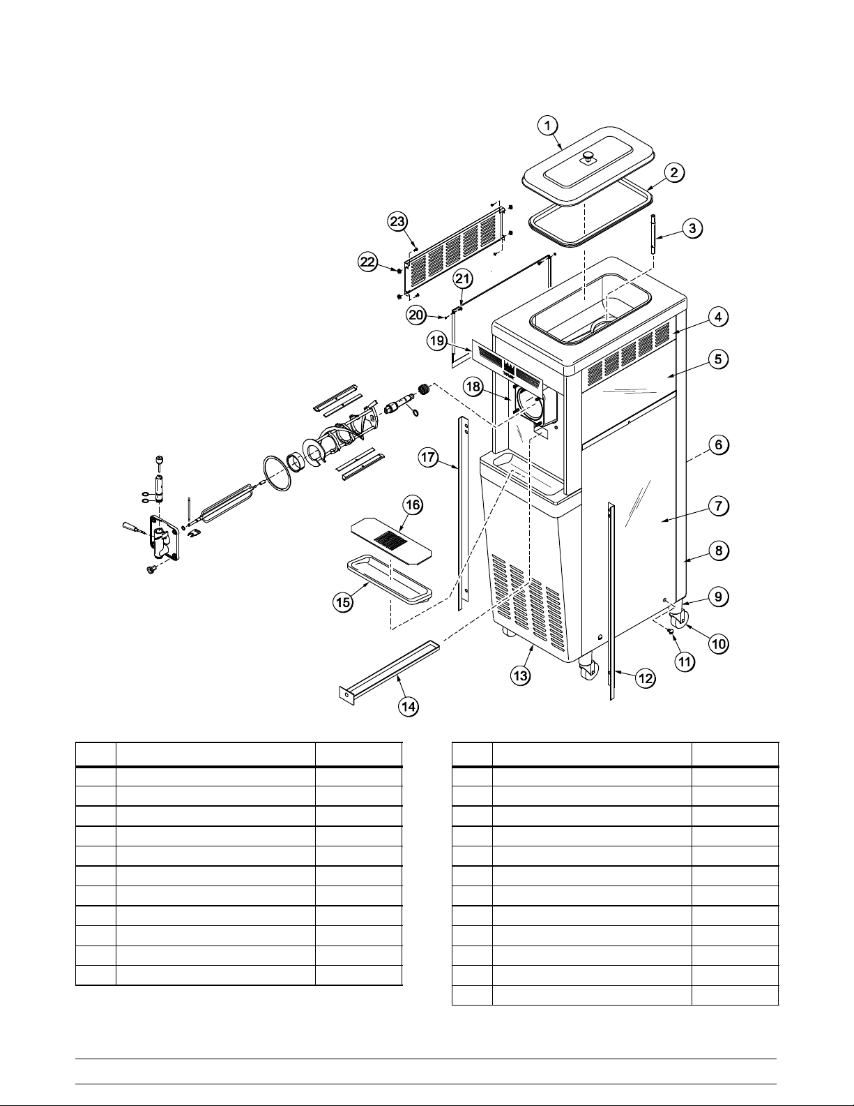
Model 341
Item Description Part No.
1 Cover A.-Hopper X38458
2 Gasket-Hopper Cover 038375
3 Tube-Feed 015176-9
4 Louver-Side--Top 051192
5 Panel-Upper Side (Left/Right) 024576
6 Panel-Rear 013637
7 Panel A.-Lower Side (Left/Right) X24397
8 Trim--Rear Corner 013620
9 Adapter A.-Caster X18915
10 Wheel-Caster 018794
11 Screw--1/4--20 x 3/8 Sltd Rd 011694
091102
Item Description Part No.
12 Angle--Panel-- R 013828
13 Panel-Service 013638-SP1
14 Pan-Drip 035034
15 Tray-Drip 013690
16 Shield-Splash 022763
17 Angle--Panel-- L 013829
18 Panel A.-Front X46881
19 Decal--Dec 048359
20 Washer--Plastic Pivot 013808
21 Screw--10--24 x 1/2 Torx Truss 002077
22 Nut--10--32 Whiz Flange 020983
23 Screw--10--32 x 1/2 Serrated 020982
6
Models 340, 341, 342Operator Parts Identification
Model 342
Item Description Part No.
1 Cover A.-Hopper X38458
2 Gasket-Hopper Cover 038375
3 Tube-Feed 015176-9
4 Louver-Side Top 051191
5 Panel-Upper Right Side 028701
6 Panel-Rear 017563
7 Panel A.-Lower Right Side X44855
*8 Trim--Rear Corner--Right 013663
9 Adapter A.-Caster X18915
10 Wheel-Caster 018794
11 Screw --1/4 --20 x 3/8 Sltd Round 011694
12 Angle--Panel-- Right 013828
13 Panel-Service 024439-SP1
Models 340, 341, 342 Operator Parts Identification
Item Description Part No.
14 Tray-Drip 014533
15 Shield-Splash 037041
16 Angle--Panel-- Left 013829
17 Panel A.-Lower Left Side X44853
18 Panel A.-Front X25807
19 Decal--Dec 021872
20 Pan-Drip 027503
21 Panel-Upper Left Side 028700
22 Washer--Plastic Pivot 013808
23 Screw--10--24 x 1/2 Torx Truss 002077
24 Nut--10--32 Whiz Flange Locknut 020983
25 Screw--10--32 x 1/2 Serr. Hwh 020982
*Trim --Rear Corner--Left -- 013761 (Not Shown)
091102
7
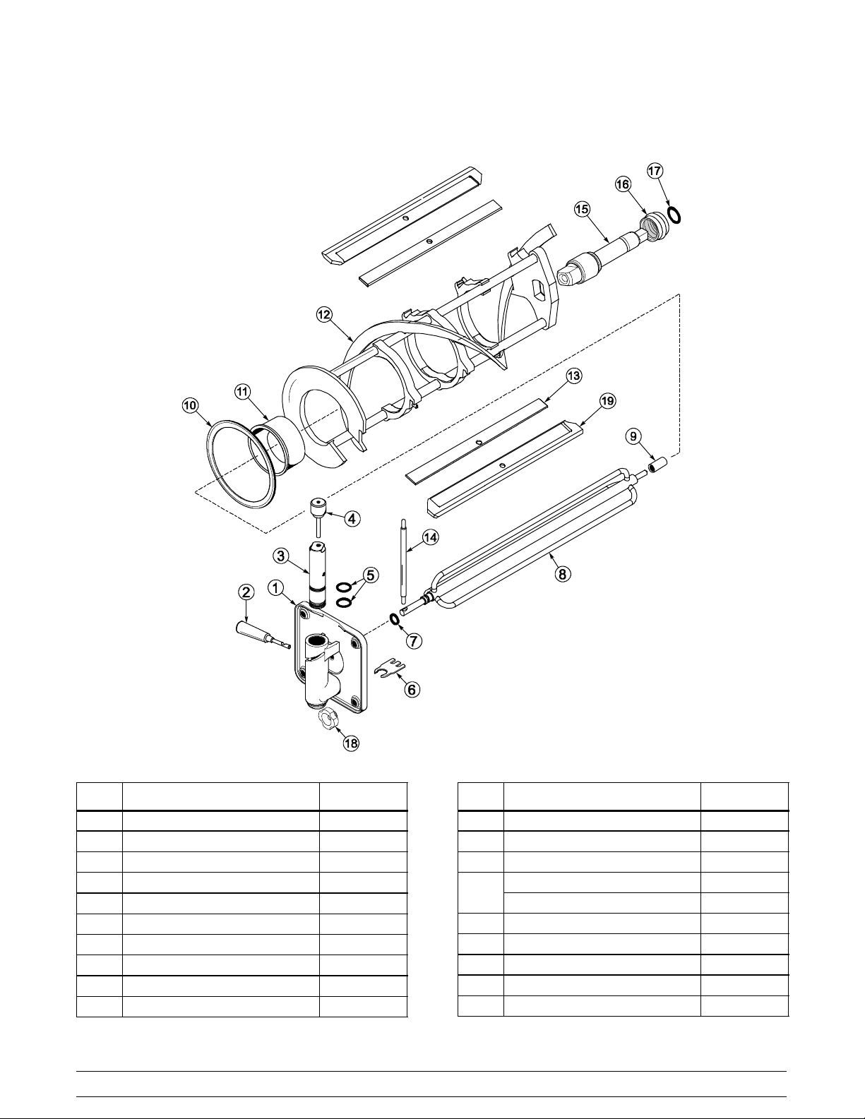
Models 340, 341, 342 Beater Door Assembly
ITEM DESCRIPTION PART NO.
1 DOOR A.-PARTIAL X39248-SER
2 HANDLE A.-DRAW-SLUSH BLK X47384
3 VALVE-DRAW 047734
4 PIN A.-VALVE HANDLE X25929
5 O-RING-1 OD x .139 W 032504
6 BUSTER-ICE 047735
7 O-RING-.291 ID x .080 W 018550
8 TORQUE ASSEMBLY X14488
9 BEARING-GUIDE 014496
10 GASKET-DOOR-5.109D x 5.63 014030
091102
ITEM DESCRIPTION PART NO.
11 BEARING-FRONT 013116
12 BEATER A.-7 QT-1 PIN X46233
13 CLIP-SCRAPER BLADE*8.75 046238
TORQUE ARM (340/341) 014500
14
TORQUE ARM (342) 029549
15 SHAFT-BEATER 035418
16 SEAL-DRIVE SHAFT 032560
17 O-RING-7/8OD x .139 W 025307
18 NUT-STUD 5/16-18 X 11/16 029880
19 BLADE-SCRAPER-PLASTIC 046237
8
Models 340, 341, 342Operator Parts Identification
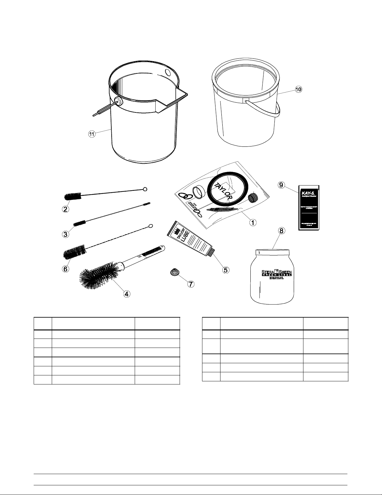
Accessories
Item Description Part No.
1 Kit A.-Tune Up X39969
2 Brush-Rear Bearing 013071
3 Brush-Double Ended 013072
4 Brush-Mix Pump Body 023316
5 Lubricant-Taylor Lube 047518
6 Brush-Draw Valve 013073
Models 340, 341, 342 Operator Parts Identification
Item Description Part No.
7 Cap-Restrictor 020213
8 Sanitizer--Stera Sheen
(Model 342 only)
9 Sanitizer--Kay 5 (340 & 341) 041082
10 Pail--6 Qt. (Model 340) 023348
11 Pail--10 Qt. (341 & 342) 013136
9
065293
091102
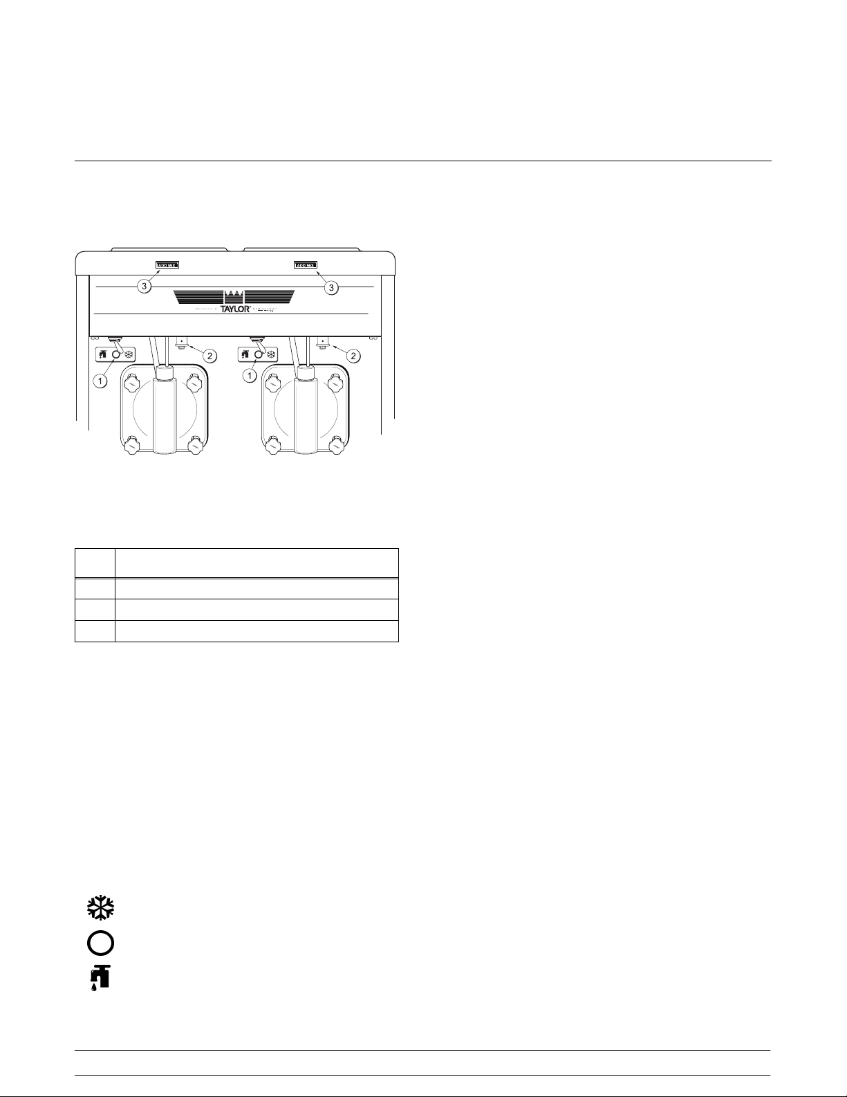
Section 5 Important: To the Operator
Control Switch
The center position is “OFF”. The left position is
“WASH”, which activates only the beater motor. The
right position is “AUTO”, which activates the beater
motor and the refrigeration system.
Consistency Control
The viscosity (thickness) of the slush is controlled by
a sensing device called the consistency control. The
consistency control knob is located under the control
channel. To achieve a thicker slush, turn the knob
clockwise and counterclockwise to achieve a
thinner slush consistency.
Allow the refrigeration system to cycle on and cycle off
two or three times before an accurate consistency can
Figure 2
be evaluated.
Item Description
1 Control Switch
2 Consistency Control
3 Indicator Light − “Add Mix”
Symbol Definitions
To better communicate in the International arena, the
words on many of our operator switches and buttons
have symbols to indicate their functions. Your Taylor
equipment is designed with these International
symbols.
The following chart identifies the symbol definitions
used on the operator switches.
= ON/AUTO
= OFF
= WASH
Indicator Light - “Add Mix”
A mix level indicating light is located on the front of the
machine. When the light is on, it indicates that the mix
hopper has a low supply of mix and should be refilled
as soon as possible. If mix is not added, a freeze-up
may occur, causing eventual damage to the beater,
blades, drive shaft, and freezer door.
For Your Information
The Models 340 and 341 come equipped with an
optional rack assembly and four syrup jars. Each syrup
jar holds 16 ounces (453.6 grams) of syrup. One pump
stroke will dispense 1/4 ounce (7 grams) of syrup.
Because of the many different types of syrups on the
market today, the syrup to slush ratio will vary. Consult
the label or manufacturer for the proper amount of
syrup for the desired drink size.
To serve slush product, simply add the flavor and open
the draw valve. The slush product should blend with
the syrup with no stirring necessary. If it does not, the
product is too thick and the consistency control should
be adjusted to a thinner consistency.
10
Models 340, 341, 342Important: To the Operator
Section 6 Operating Procedures
The Model 341 has been selected to illustrate the
pictured step-by-step operating procedures for the
models contained in this manual. Each unit has a 20
quart (18.9 liter) mix hopper and the freezing cylinder
holds 7 quarts (6.6 liters) of slush product. The Model
342 has two mix hoppers and two freezing cylinders;
therefore, duplicate (where it applies) the following
steps for the second side of the Model 342.
We begin our instructions at the point where we enter
the store in the morning and find the parts
disassembled and laid out to air dry from the previous
night’s brush cleaning.
These opening procedures will illustrate how to
assemble these parts into the freezer, sanitize them,
and prime the freezer with slush base in preparation to
serve the first portion.
If you are disassembling the machine for the first time,
or need information to get to this starting point in our
instructions, turn to page 20, “Disassembly” and start
there.
Insert the drive shaft into the freezing cylinder, (square
end first) and into the rear shell bearing, until the seal
fits securely over the rear shell bearing. Be certain the
drive shaft fits into the drive coupling without binding.
Figure 3
Assembly
MAKE SURE CONTROL SWITCH IS IN THE
“OFF” POSITION. Failure to do so may cause injury
from electrocution or hazardous moving parts .
Note: When lubricating parts, use an approved food
grade lubricant (example: Taylor Lube).
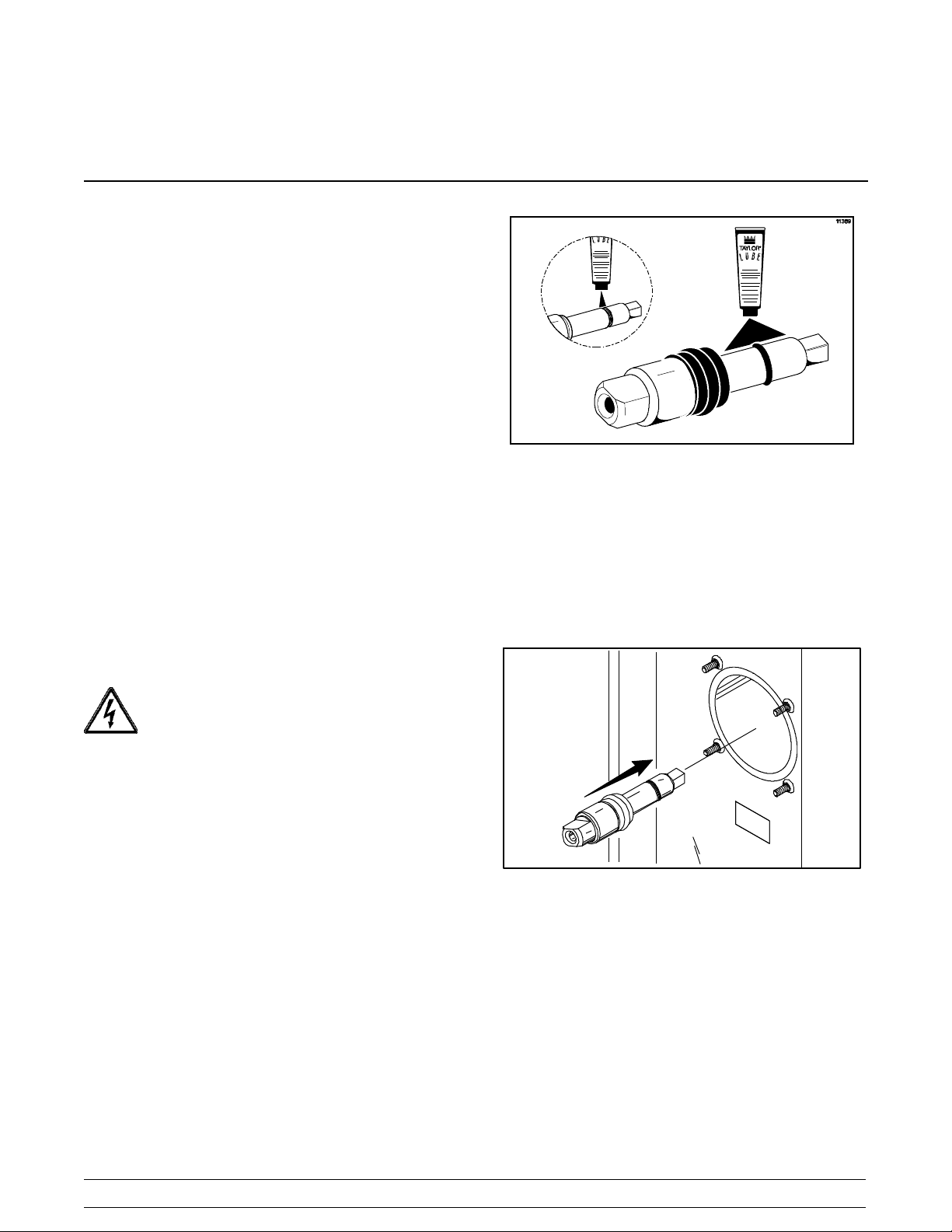
Step 1
Install the beater drive shaft. Slide the o-ring into the
first groove on the drive shaft. Lubricate the groove,
o-ring, and shaft portion that comes in contact with the
bearing on the beater drive shaft. DO NOT lubricate
the square end of the drive shaft. Slide the seal over
the shaft and groove until it snaps into place. Fill the
inside portion of the seal with 1/4” more lubricant and
evenly lubricate the flat side of the seal that fits onto the
rear shell bearing.
Figure 4
Step 2
Before installing the beater assembly, check the
scraper blades for any nicks or signs of wear. If any
nicks are present or if the blade is worn, replace both
blades.
Models 340, 341, 342 Operating Procedures
11
 Loading...