

Taylor Freezer 150, 152, 162, 168 Operation Manual

Models 150, 152, 162, & 168
Taylormate
Soft Serve Freezers
Operating Instructions
028749-M
8/13/08 (Original Publication)
(Updated 8/22/10)

Complete this page for quick reference when service is required:
Taylor Distributor:
Address:
Phone:
Service:
Parts:
Date of Installation:
Information found on data plate:
Model Number:
Serial Number:
Electrical Specs: Voltage Cycle
Phase
Maximum Fuse Size: Amps
Minimum Wire Ampacity: Amps
Part Number:
E August, 2008 Taylor (Original Publication)
(Updated November, 2010)
All rights reserved.
028749--M
The word Taylor and the Crown design
are registered trademarks in the United States
of America and certain other countries.
Taylor Company
750 N. Blackhawk Blvd.
Rockton, IL 61072

Table of Contents
Section 1 To the Installer 1............................................
Installer Safety 1........................................................
Site Preparation 1.......................................................
Air Cooled Units 2.......................................................
Electrical Hook--Up Installation For
60 Cycle, 1 Phase, Supplied With Cord and Plug 2..........................
Electrical Connections For Models Without Cord and Plug Supplied 2.........
Beater Rotation 3.......................................................
Refrigerant 3...........................................................
Section 2 To the Operator 4...........................................
Compressor Warranty Disclaimer 4.......................................
Section 3 Safety 5....................................................
Section 4 Operator Parts Id en t ificatio n 7...............................
Model 150 7............................................................
Model 152 8............................................................
Model 162 9............................................................
Model 168 10............................................................
Models 150 & 152 Door Assembly 11.......................................
Models 162 & 168 Door Assembly 12.......................................
Models 150 and 152 Accessories 13.......................................
Models 162 and 168 Accessories 14.......................................
Section 5 Important: To the Operator 15.................................
Symbol Definitions 15....................................................
Reset Button 16.........................................................
Power Switch 16.........................................................
Feed Tube 16...........................................................
Taylor Quality Control 16..................................................
Indicator Light -- “Mix Low” 16.............................................
Mix Refrigeration Switch 16...............................................
Table of Contents Models 150, 152, 162, 168

Table of Contents -- Page 2
Separate Hopper Refrigeration (SHR) 16...................................
Cylinder Temperature Retention (CTR) 17...................................
Section 6 Operating Procedures 18.....................................
Assembly 19............................................................
Sanitizing 22............................................................
Priming 24..............................................................
Closing Procedure 25....................................................
Draining Product From the Freezing Cylinder 25.............................
Rinsing 25..............................................................
Cleaning 25.............................................................
Disassembly 26..........................................................
Brush Cleaning 26.......................................................
Section 7 Important: Operator Checklist 27..............................
During Cleaning and Sanitizing 27.........................................
Troubleshooting Bacterial Count 27........................................
Regular Maintenance Checks 27...........................................
Winter Storage 28........................................................
Section 8 Troubleshooting Guide 29....................................
Section 9 Parts Replacement Schedule 32...............................
Section 10 Parts List 33.................................................
Wiring Diagrams 42......................................................
Note: Continuing research results in steady improvements; therefore, information
in this manual is subject to change without notice.
E August, 2008Taylor (Original Publication)
(Updated November, 2010)
All rights reserved.
028749--M
The word Taylor and the Crown design
are registered trademarks in the United States
of America and certain other countries.
Models 150, 152, 162, 168 Table of Contents
Taylor Company
750 N. Blackhawk Blvd.
Rockton, IL 61072
Section 1 To the Installer
The following are general installation instructions. For
complete installation details, please see the check out
card.
cause severe injuries.
Installer Safety
This unit has many sharp edges that can
In all areas of the world, equipment should be
installed in accordance with existing local codes.
Please contact your local authorities if you have any
questions.
Care should be taken to ensure that all basic safety
practices are followed during the installation and
servicing activities related to the installation and
service of Taylor equipment.
S Only authorized Taylor service personnel
should perform installation and repairs on
the equipment.
S Authorized service personnel should consult
OSHA Standard 29CFRI910.147 or the
applicable code of the local area for the
industry standards on lockout/tagout
procedures before beginning any installation
or repairs.
S Authorized service personnel must ensure
that the proper PPE is available and worn
when required during installation and
service.
S Authorized service personnel must remove
all metal jewelry, rings, and watches before
working on electrical equipment.
The main power supply(s) to the freezer must
be disconnected prior to performing any repairs.
Failure to follow this instruction may result in personal
injury or death from electrical shock or hazardous
moving parts as well as poor performance or damage
to the equipment.
Note:Allrepairsmustbeperformedbyan
authorized Taylor Service Technician.
Site Preparation
Review the area the unit is to be installed in before
uncrating the unit, making sure that all possible
hazards the user or equipment may come into have
been addressed.
For Indoor Use Only: This unit is designed to operate
indoors, under normal ambient temperatures of
70_-75_F(21_-24_C). The freezer has successfully
performed in high ambient temperatures of
104_(40_C) at reduced capacities.
This unit must NOT be installed in an area
where a water jet or hose can be used. NEVER use a
water jet or hose to rinse or clean the unit. Failure to
follow this instruction may result in electrocution.
This unit must be installed on a level surface
to avoid the hazard of tipping. Extreme care should be
taken in moving this equipment for any reason. Two or
more persons are required to safely move this unit.
Failure to comply may result in personal injury or
equipment damage.
Uncrate the unit and inspect it for damage. Report any
damage to your Taylor Distributor.
This piece of equipment is made in the USA and has
USA sizes of hardware. All metric conversions are
approximate and vary in size.
090218
Models 150, 152, 162, 168 To the Installer
1
Air Cooled Units
The models 150 and 152 require a minimum of 6” (152
mm) of clearance around both sides. Install the skirt
provided on the right side of the unit and place the back
of the unit against a wall to prevent recirculation of
warm air. The model 162 requires 6” (152 mm) on all
sides and the skirt installed on the rear of the unit. The
model 168 requires 3” (76 mm) on all sides and the
skirt installed on the rear of the unit. Minimum air
clearances must be met to assure adequate air flow for
optimum performance.
4. Route incoming permanent wiring through 7/8”
(22 mm) hole in base pan.
5. Connect two power supply leads. Attach ground
(earth) wire to the grounding lug inside the
electrical box.
6. Be sure the unit is properly grounded before
applying power.
FOLLOW YOUR LOCAL ELECTRICAL CODES!
These machines are designed for indoor use only.
DO NOT install the machines in an area where
a water jet could be used. Failure to follow this
instruction may result in serious electrical shock.
Electrical Hook--Up Installation For
60 Cycle, 1 Phase, Supplied With Cord and Plug
This equipment is supplied with a 3--wire cord and
grounding type plug for connection to a single phase,
60 cycle, branch circuit supply. This unit must be
plugged into a properly grounded receptacle. The cord
and plug provided for 115/60/1, is 20 amp; therefore
the wall outlet must also be 20 amp. Check the data
label, located on the side panel, for electrical
specifications.
Electrical Connections For
Models Without Cord and Plug Supplied
Each freezer requires one power supply for each data
label. Check the data label(s) on the freezer for branch
circuit overcurrent protection or fuse, circuit ampacity ,
and electrical specifications. Refer to the wiring
diagram provided inside of the control box, for proper
power connections.
In the United States, this equipment is intended to be
installed in accordance with the National Electrical
Code (NEC), ANSI/NFPA 70--1987. The purpose of
the NEC code is the practical safeguarding of persons
and property from hazards arising from the use of
electricity. This code contains provisions considered
necessary for safety. Compliance therewith and
proper maintenance will result in an installation
essentially free from hazard! In all other areas of the
world, equipment should be installed in accordance
with the existing local codes. Please contact your local
authorities.
Permanent wiring may be employed if required by local
codes. Instructions for conversion to permanent wiring
are as follows:
1. Be sure the freezer is electrically disconnected.
2. Remove the appropriate panel and locate the
small electrical box at the base of the freezer.
3. Remove the factory--installed cord and strain
relief bushing.
101122
CAUTION: THIS EQUIPMENT MUST BE
PROPERLY GROUNDED! FAILURE TO DO SO
CAN RESULT IN SEVERE PERSONAL INJURY
FROM ELECTRICAL SHOCK!
This unit is provided with an equipotential
grounding lug that is to be properly attached to the rear
of the frame by the authorized installer. The installation
location is marked by the equipotential bonding
symbol (5021 of IEC 60417-1) on both the removable
panel and the equipment’s frame.
2
Models 150, 152, 162, 168To th e Installer
S Stationary appliances which are not
equipped with a power cord and a plug or
another device to disconnect the appliance
from the power source must have an all-pole
disconnecting device with a contact gap of
at least 3mm installed in the external
installation.
S Appliances that are permanently connected
to fixed wiring and for which leakage
currents may exceed 10 mA, particularly
when disconnected, not used for long
periods, or during initial installation, shall
have protective devices such as a GFI to
protect against the leakage of current,
installed by authorized personnel to the local
codes.
S Supply cords used with this unit shall be
oil-resistant, sheathed flexible cable, not
lighter than ordinary polychloroprene or
other equivalent synthetic
elastomer-sheathed cord (Code designation
60245 IEC 57) installed with the proper cord
anchorage to relieve conductors from strain,
including twisting, at the terminals and
protect the insulation of the conductors from
abrasion.
Refrigerant
In consideration of our environment, T aylor
proudly uses only earth friendly HFC refrigerants. The
HFC refrigerant used in this unit is R404A. This
refrigerant is generally considered non-toxic and
non-flammable, with an Ozone Depleting Potential
(ODP) of zero (0).
However, any gas under pressure is potentially
hazardous and must be handled with caution.
NEVER fill any refrigerant cylinder completely with
liquid. Filling the cylinder to approximately 80% will
allow for normal expansion.
Refrigerant liquid sprayed onto the skin may
cause serious damage to tissue. Keep eyes and skin
protected. If refrigerant burns should occur, flush
immediately with cold water. If burns are severe, apply
ice packs and contact a physician immediately.
Taylor reminds technicians to be cautious of
government laws regarding refrigerant recovery,
recycling, and reclaiming systems. If you have any
questions regarding these laws, please contact the
factory Service Department.
Beater Rotation
Beater rotation must be clockwise as viewed
looking into the freezing cylinder.
Note: The following procedures should be
performed by an authorized service technician.
To correct rotation on a three--phase unit, interchange
any two incoming power supply lines at freezer main
terminal block only. To correct rotation on a
single--phase unit, change the leads inside the beater
motor. (Follow diagram printed on motor.)
Electrical connections are made directly to the
terminal block provided in the splice box, mounted on
the base pan on each side of the model 168, and
located in the splice boxes mounted mid--level on the
frame channel on the sides of the model 162.
WARNING: R404A refrigerant used in
conjunction with polyolester oils is extremely moisture
absorbent. When opening a refrigeration system, the
maximum time the system is open must not exceed 15
minutes. Cap all open tubing to prevent humid air or
water from being absorbed by the oil.
Models 150, 152, 162, 168 To the Installer
3

Section 2 To the Operator
The freezer you have purchased has been carefully
engineered and manufactured to give you dependable
operation. The Taylor Company models covered in this
manual consist of the following: 150, 152, 162 and 168.
These units, when properly operated and cared for, will
produce a consistent quality product. Like all
mechanical products, they will require cleaning and
maintenance. A minimum amount of care and
attention is necessary if the operating procedures
outlined in this manual are followed closely.
This Operator’s Manual should be read before
operating or performing any maintenance on your
equipment.
These units will NOT eventually compensate and
correct for any errors during the set--up or filling
operations. Thus, the initial assembly and priming
procedures are of extreme importance. It is strongly
recommended that personnel responsible for the
equipment’s operation, both assembly and
disassembly, go through these procedures together in
order to be properly trained and to make sure that no
misunderstandings exist.
In the event you should require technical assistance,
please contact your local authorized Taylor Distributor.
Note: Warranty is valid only if the parts are authorized
Taylor parts, purchased from an authorized Taylor
Distributor, and the required service work is provided
by an authorized Taylor service technician. Taylor
reserves the right to deny warranty claims on
equipment or parts if non--approved parts or
refrigerant were installed in the machine, system
modifications were performed beyond factory
recommendations, or it is determined that the failure
was caused by neglect or abuse.
Note: Constant research results in steady
improvements; therefore, information in this
manual is subject to change without notice.
If the crossed out wheeled bin symbol is
affixed to this product, it signifies that this product is
compliant with the EU Directive as well as other similar
legislation in effect after August 13, 2005. Therefore,
it must be collected separately after its use is
completed, and cannot be disposed as unsorted
municipal waste.
The user is responsible for returning the product to the
appropriate collection facility, as specified by your local
code.
For additional information regarding applicable local
laws, please contact the municipal facility and/or local
distributor.
Compressor Warranty Disclaimer
The refrigeration compressor(s) on this machine are
warranted for the term indicated on the warranty card
accompanying this machine. However, due to the
Montreal Protocol and the U.S. Clean Air Act
Amendments of 1990, many new refrigerants are
being tested and developed, thus seeking their way
into the service industry. Some of these new
refrigerants are being advertised as drop--in
replacements for numerous applications. It should be
noted that, in the event of ordinary service to this
machine’s refrigeration system, only the refrigerant
specified on the affixed data label should be used.
The unauthorized use of alternate refrigerants will void
your compressor warranty. It will be the owner ’s
responsibility to make this fact known to any technician
he employs.
It should also be noted that Taylor does not warrant the
refrigerant used in its equipment. For example, if the
refrigerant is lost during the course of ordinary service
to this machine, Taylor has no obligation to either
supply or provide its replacement either at billable or
unbillable terms. Taylor does have the obligation to
recommend a suitable replacement if the original
refrigerant is banned, obsoleted, or no longer available
during the five year warranty of the compressor.
The Taylor Company will continue to monitor the
industry and test new alternates as they are being
developed. Should a new alternate prove, through our
testing, that it would be accepted as a drop--in
replacement, then the above disclaimer would
become null and void. To find out the current status of
an alternate refrigerant as it relates to your
compressor warranty, call the local Taylor Distributor
or the Taylor Factory. Be prepared to provide the
Model/Serial Number of the unit in question.
4
Models 150, 152, 162, 168To th e Operator
Section 3 Safety
We at Taylor Company are concerned about the safety
of the operator when he or she comes in contact with
the freezer and its parts. Taylor has gone to extreme
efforts to design and manufacture built--in safety
features to protect both you and the service technician.
As an example, warning labels have been attached to
the freezer to further point out safety precautions to the
operator.
IMPORTANT! Failure to adhere to the
following safety precautions may result in severe
personal injury. Failure to comply with these warnings
may damage the machine and its components.
Component damage will result in part replacement
expense and service repair expense.
To Operate Safely:
DO NOT operate the freezer without reading
the Operator Manual. Failure to follow this instruction
may result in equipment damage, poor freezer
performance, health hazards, or personal injury.
S Appliances that are permanently connected
to fixed wiring and for which leakage
currents may exceed 10 mA, particularly
when disconnected or not used for long
periods, or during initial installation, shall
have protective devices such as a GFI, to
protect against the leakage of current,
installed by the authorized personnel to the
local codes.
S Supply cords used with this unit shall be
oil-resistant, sheathed flexible cable not
lighter than ordinary polychloroprene or
other equivalent synthetic
elastomer-sheathed cord (Code designation
60245 IEC 57) installed with the proper cord
anchorage to relieve conductors from strain,
including twisting, at the terminals and
protect the insulation of the conductors from
abrasion.
Failure to follow these instructions may result in
electrocution. Contact your local authorized Taylor
Distributor for service.
DO NOT use a water jet to clean or rinse the
freezer. Failure to follow these instructions may result
in serious electrical shock.
This equipment is provided with a grounding lug
that is to be properly attached to the rear of the frame
by the authorized installer. The installation location is
marked by the equipotential bonding symbol (5021 of
IEC 60417--1) on the removable panel and the frame.
S DO NOT allow untrained personnel to
operate this machine.
S DO NOT put objects or fingers in door
spout.
S DO NOT operate the freezer unless it is
properly grounded.
S DO NOT operate the freezer with larger
fuses than specified on the freezer data
label.
S DO NOT operate the freezer unless all
service panels and access doors are
restrained with screws.
S DO NOT remove the freezer door or beater
assembly unless the control switches are in
the “OFF” position.
S DO NOT attempt any repairs unless the
main power supply to the freezer has been
disconnected.
Models 150, 152, 162, 168 Safety
Failure to follow these instructions may result in severe
personal injury from hazardous moving parts.
5

S DO NOT put objects or fingers in fill or
discharge openings. Failure to follow this
instruction may result in contaminated
product or personal injury from blade
contact.
S USE EXTREME CAUTION when removing
the beater assembly. The scraper blades
are very sharp and may cause injury.
DO NOT obstruct air intake and discharge openings:
S 150 and 152: Minimum of 6” (152 mm) of
clearance around both sides. Install the skirt
provided on the right side of the unit and
place the back of the unit against a wall to
prevent recirculation of warm air.
S 162: Minimum of 6” (152 mm) on all sides.
Install the skirt provided on the rear of the
unit.
S 168: Minimum of 3” (76 mm) on all sides.
Install the skirt provided on the rear of the
unit.
Failure to follow this instruction may cause poor
freezer performance and damage to the machine.
This freezer must be placed on a level
surface. Failure to comply may result in personal injury
or equipment damage.
These freezers are designed to operate indoors, under
normal ambient temperatures of 70_-- 7 5 _F
(21_-- 2 4 _C). The freezers have successfully performed in high ambient temperatures of 104_F(40_C)
at reduced capacities.
NOISE LEVEL: Airborne noise emission does not
exceed 78 dB(A) when measured at a distance of 1.0
meter from the surface of the machine and at a height
of 1.6 meters from the floor.
6
Models 150, 152, 162, 168Safety
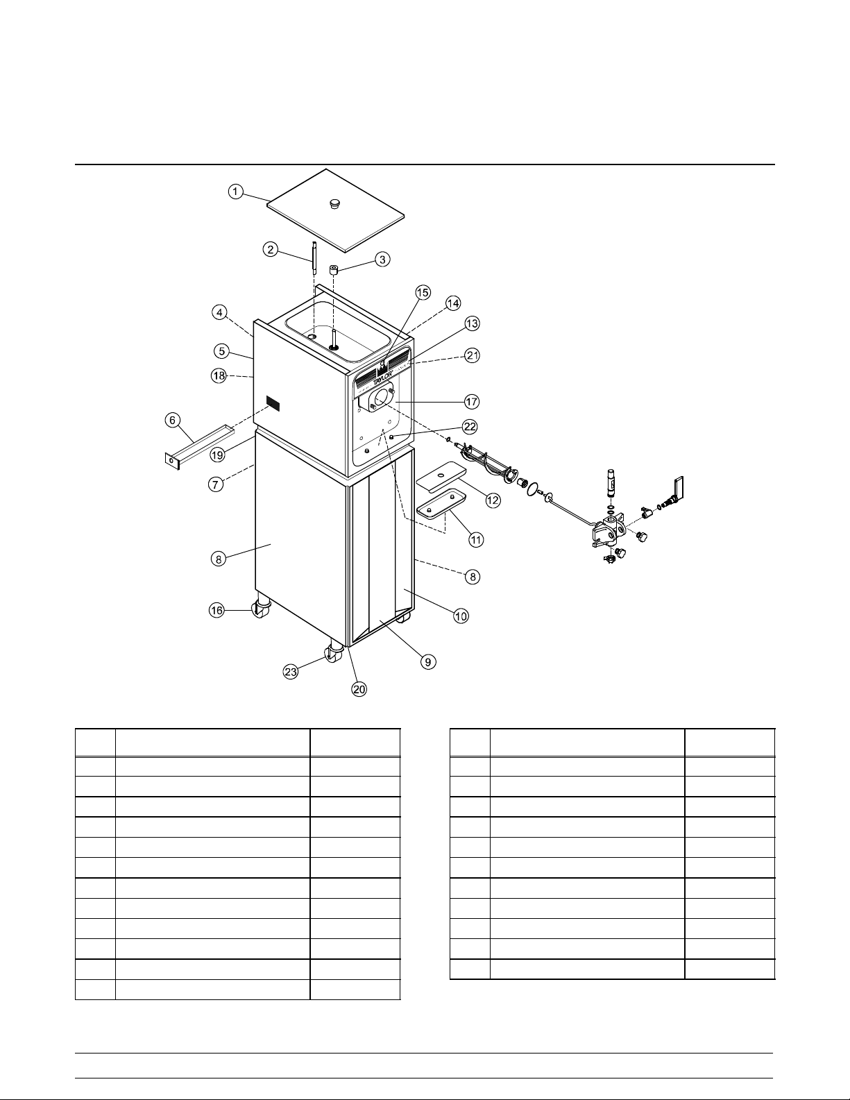
Section 4 Operator Parts Identification
Model 150
Figure 1
Item Description Part No.
1 Cover A.--Hopper X48690
2 Tube--Feed--.166 Hole 035819
3 Float A.-- Mix Level X39690
4 Panel-- Back Top 050429
5 Panel-- Upper Side Left 030783--SS
6 Pan--Drip 11--5/8 Long 027503
7 Panel-- Back Bottom 050430
8 Panel-- Lower Side 030792--SS
9 Panel-- Insert 025533--SS
10 Panel A.--Lower Front X25518
11 Tray--Drip 10-- 7/8 x 4--7/16 025062
12 Shield--Splash 11--1/4 x 4--13/16 025063
Models 150, 152, 162, 168 Operator Parts Identification
Item Description Part No.
13 Decal--Decorative-- Taylor 047667
14 Panel--Upper Side Right 030784--SS
15 Light--Amber--Round Mix Low 039707
16 Caster--3” Swivel 012227
17 Panel A.--Front X25036
18 Trim-- Top Back Panel 025536
19 Trim-- Middle Back Panel 025537
20 Trim--Side & Front 025528
21 Plate--Decorative 041034--SS
22 Holder--Drip Tray 035866
23 Caster--3” Rigid 012226
7
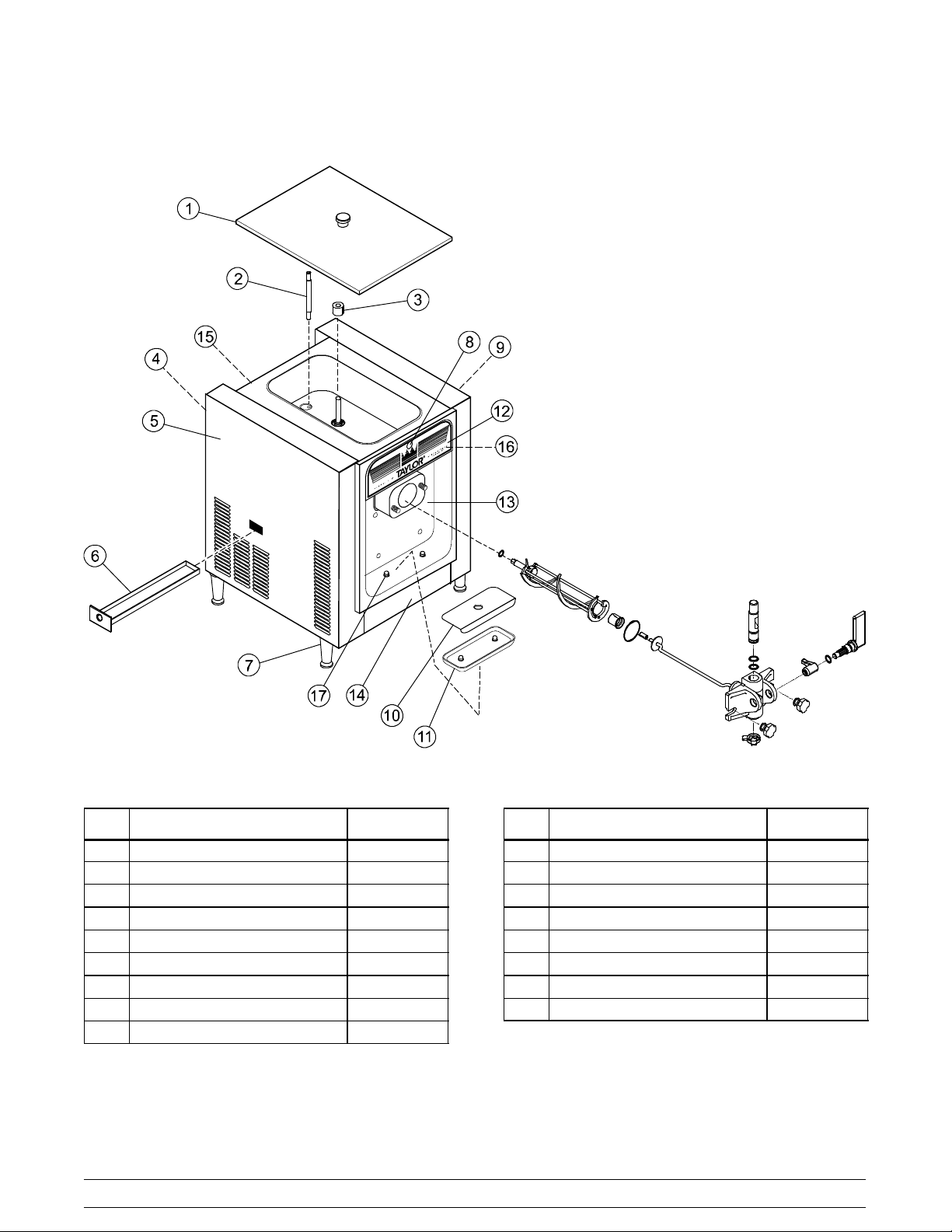
Model 152
Item Description Part No.
1 Cover A.--Hopper X48690
2 Tube--Feed--.166 Hole 035819
3 Float A.-- Mix Level X39690
4 Panel-- Rear 051556
5 Panel-- Side Left 051557
6 Pan--Drip 11--5/8 Long 027503
7 Leg--Plastic 024755
8 Light--Amber--Round Mix Low 039707
9 Panel-- Side Right 051558
Figure 2
8
Item Description Part No.
10 Shield--Splash 11--1/4 x 4--13/16 025063
11 Tray--Drip 10-- 7/8 x 4--7/16 025062
12 Decal--Decorative-- Taylor 047667
13 Panel A.--Front X25036
14 Trim--Front 025862--SS
15 Trim-- Top Back 025866
16 Plate--Decorative 041034--SS
17 Holder--Drip Tray 035866
Models 150, 152, 162, 168Operator Parts Identification
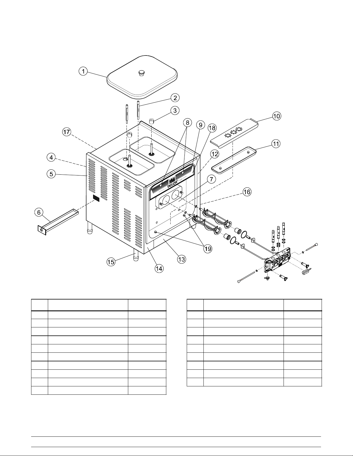
Model 162
Figure 3
Item Description Part No.
1 Cover A.--Hopper X37963--SER
2 Tube--Feed--.166 Hole 030797
3 Float A.-- Mix Level X39690
4 Panel-- Rear 047276--SS
5 Panel-- Side--Left 050213--SS
6 Pan--Drip 19--1/2 Long 035034
7 Panel A.--Front X30711
8 Light--Amber--Round Mix Low 039707
9 Decal-- Decorative--Taylor 047666
10 Shield-- Splash 030789
Models 150, 152, 162, 168 Operator Parts Identification
Item Description Part No.
11 T r a y -- D r i p -- 1 6 -- 7 / 8 x 4 -- 3 / 8 030565
12 Panel--Front Right 035933-- SS
13 Trim--Front 050212--SS
14 Panel--Front Left 035932--SS
15 Leg-- 4.250” (With O--Ring) 013458
16 Panel--Side Right 050214--SS
17 Trim--Panel--Rear 035923
18 Plate--Decorative 039723--SS
19 Holder--Drip Tray 035866
9
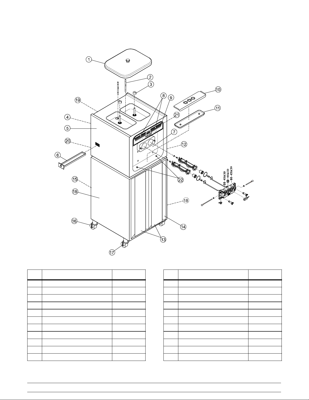
Model 168
Item Description Part No.
1 Cover A.--Hopper X37963--SER
2 Tube--Feed--.166 Hole SS 030797
3 Float A.-- Mix Level X39690
4 Panel-- Top Back 030790--SS
5 Panel-- Upper Side Left 030783--SS
6 Pan--Drip 17--1/4” Long 027504
7 Panel A.--Front X30711
8 Light--Amber--Round Mix Low 039707
9 Decal-- Decorative--Taylor 047666
10 Shield--Splash 17--5/8 Long 030789
11 Tray-- Drip 16-- 7/8 Long 030565
Figure 4
10
Item Description Part No.
12 Panel--Upper Side Right 030784--SS
13 Insert--Front Panel 030773-- SS
14 Panel A.--Lower Front X30747
15 Panel--Bottom Back 055833
16 Caster--3” Rigid (Rear) 012226
17 Caster--3” Swivel (Front) 012227
18 Panel--Lower Side--Right/Left 030792--SS
19 Trim-- Top Back Panel 030775
20 Trim-- Middle Back Panel 030795
21 Plate--Decorative 039723--SS
22 Holder--Drip Tray 035866
Models 150, 152, 162, 168Operator Parts Identification
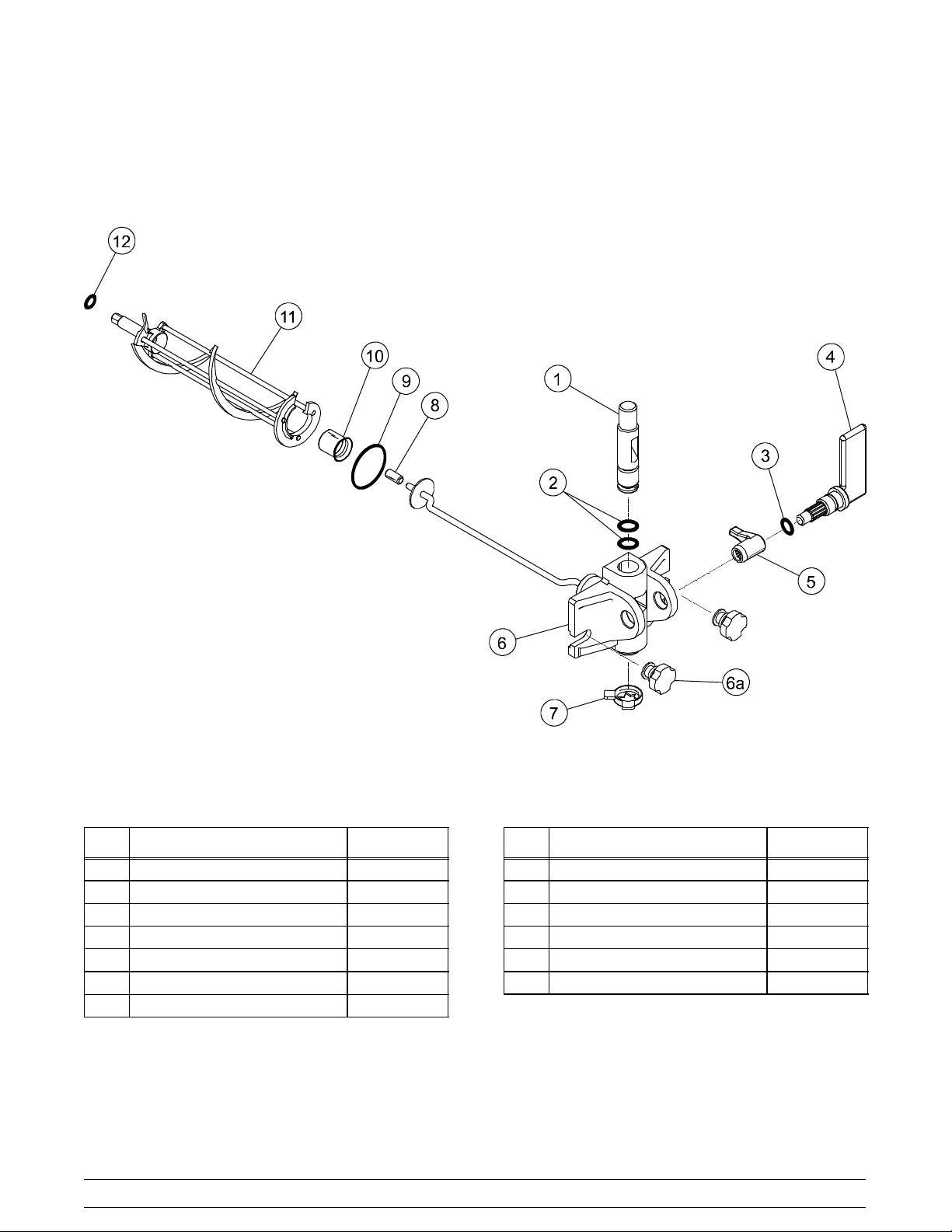
Models 150 & 152 Door Assembly
Figure 5
Item Description Part No.
1 Valv e - -Dra w 024763
2 O--Ring--7/8 OD x .103 W 014402
3 O--Ring--3/4 OD x .103 W 015835
4 Handle-- Draw 024762
5 Arm--Valve Lifter 024761
6 Door A.--1 Spout X38959--SER
6a Nut--Stud 034829
Models 150, 152, 162, 168 Operator Parts Identification
Item Description Part No.
7 Cap--Design 1.010” ID -- 6 Point 014218
8 Bearing--Guide 014496
9 O-- Ring--2--3/4 OD x .139 W 019998
10 Bearing--Front 023262
11 Beater A. X24689
12 O-- Ring-- 13/16 OD .139 W 021278
11
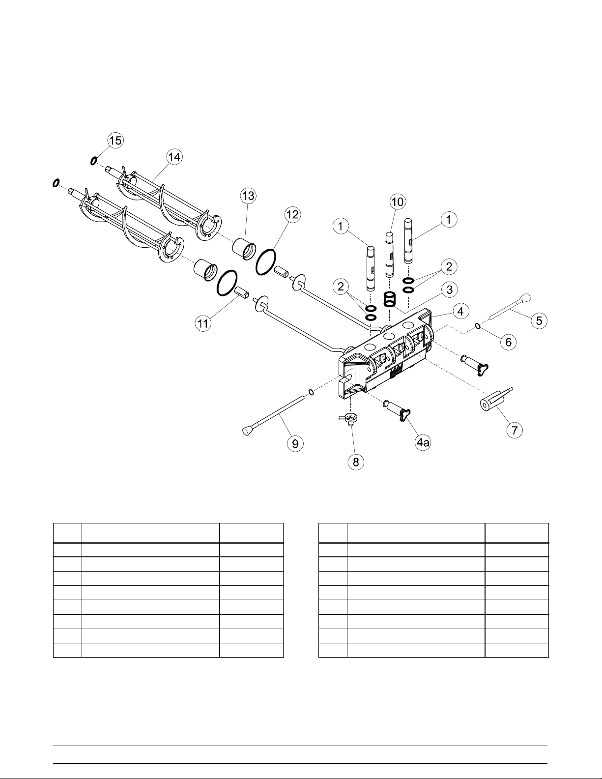
Models 162 & 168 Door Assembly
Item Description Part No.
1 Valv e - -Dra w 024763
2 O--Ring--7/8 OD x .103 W 014402
3 Seal-- Draw Valve (H--Ring) 030930
4 Door A.--3 Spout X56906--SER
4a Nut--Stud 056802
5 Pin A.--Pivot Short X38539
6 O--Ring--5/16 OD x .070 W 016272
7 Handle-- Draw Valve 030564
Figure 6
12
Item Description Part No.
8 Cap--Design 1.010” ID -- 6 Point 014218
9 Pin A.--Pivot Long X38538
10 Valve--Draw--Center 031164
11 Bearing--Guide 014496
12 O-- Ring-- 2-- 3/4 OD x .139 W 019998
13 Bearing--Front 023262
14 Beater A. X24689
15 O-- Ring-- 13/16 OD x .139 W 021278
Models 150, 152, 162, 168Operator Parts Identification
 Loading...