

Page 1

Models 8751/8754
Pump Style
Soft Serve Freezers
Operating Instructions
056485--M
2/01/02
Page 2
Complete this page for quick reference when service is required:
Taylor Distributor:
Address:
Phone:
Service:
Parts:
Date of Installation:
Information found on the data label:
Model Number:
Serial Number:
Electrical Specs: Voltage Cycle
Phase
Maximum Fuse Size: A
Minimum Wire Ampacity: A
E February, 2002 Taylor
All rights reserved.
056485--M
The word T aylor and the Crown design
are registered trademarks in the United States
of America and certain other countries.
Taylor Company
750 N. Blackhawk Blvd.
Rockton, IL 61072
Page 3

Table of Contents
Section 1 To the Installer 1............................................
Water Connections (Water Cooled Units Only) 1............................
Air Cooled Units 1.......................................................
Electrical Connections 1.................................................
Section 2 To the Operator 2...........................................
Compressor Warranty Disclaimer 2.......................................
Section 3 Safety 3....................................................
Section 4 Operator Parts Id en t ificatio n 4...............................
Model 8751 4..........................................................
Model 8754 5..........................................................
Model 8751 Single Spout Door and Beater Assembly 6......................
Model 8754 Three Spout Door and Beater Assembly 7......................
Air/Mix Pump 8.........................................................
Accessories 9..........................................................
Section 5 Important: To the Operator 10.................................
Symbol Definitions 11....................................................
Power Switch 11.........................................................
Indicator Lights 11.......................................................
MIX REF Key 11.........................................................
STANDBY Key 11........................................................
WASH Key 12...........................................................
AUTO Key 12...........................................................
Pump Key 12............................................................
Reset Button 12.........................................................
Air/Mix Pump Reset Mechanism 12........................................
Adjustable Draw Handle 12...............................................
Feed Tube (Back--up Option) 13...........................................
Table of Contents Models 8751/8754
Page 4

Table of Contents -- Page 2
Section 6 Operating Procedures 14.....................................
Assembly 14............................................................
Air/Mix Pump Assembly 18................................................
Sanitizing 21............................................................
Priming 23..............................................................
Closing Procedure 24....................................................
Draining Product From the Freezing Cylinder 25.............................
Rinsing 25..............................................................
Cleaning 25.............................................................
Disassembly 26..........................................................
Brush Cleaning 26.......................................................
Section 7 Important: Operator Checklist 27..............................
During Cleaning and Sanitizing 27.........................................
Troubleshooting Bacterial Count 27........................................
Regular Maintenance Checks 27...........................................
The Air/Mix Pump Checklist 28............................................
Winter Storage 28........................................................
Section 8 Troubleshooting Guide 29....................................
Section 9 Parts Replacement Schedule 33...............................
Section 10 Parts List 34.................................................
Wiring Diagrams 44......................................................
Note: Continuing research results in steady improvements; therefore, information
in this manual is subject to change without notice.
Models 8751/8754 Table of Contents
Page 5
Section 1 To the Installer
This machine is designed for indoor use only.
DO NOT install the machine in an area where
a water jet could be used to clean or rinse the machine.
Failure to follow this instruction may result in serious
electrical shock.
Water Connections
(Water Cooled Units Only)
An adequate cold water supply must be provided with
a hand shut-off valve. On the underside rear of the
base pan, two 3/8” I.P.S. (for single-head units) or two
1/2” I.P.S. (for double-head units) water connections
for inlet and outlet have been provided for easy
hook-up. 1/2” inside diameter water lines should be
connected to the machine. (Flexible lines are
recommended, if local codes permit.) Depending on
local water conditions, it may be advisable to install a
water strainer to prevent foreign substances from
clogging the automatic water valve. There will be only
one water “in” and one water “out” connection for both
single-head and double-head units. DO NOT install a
hand shut-off valve on the water “out” line! Water
should always flow in this order: first, through the
automatic water valve; second, through the
condenser; and third, through the outlet fitting to an
opentrapdrain.
Electrical Connections
Each freezer requires one power supply for each data
label. Check the data label(s) on the freezer for fuse,
circuit ampacity and electrical specifications. Refer to
the wiring diagram provided inside of the electrical box,
for proper power connections.
In the United States, this equipment is intended to be
installed in accordance with the National Electrical
Code (NEC), ANSI/NFPA 70--1987. The purpose of
the NEC code is the practical safeguarding of persons
and property from hazards arising from the use of
electricity. This code contains provisions considered
necessary for safety. Compliance therewith and
proper maintenance will result in an installation
essentially free from hazard!
In all other areas of the world, equipment should be
installed in accordance with the existing local codes.
Please contact your local authorities.
Stationary appliances which are not equipped with a
power cord and a plug or other device to disconnect
the appliance from the power source must have an
all--pole disconnecting device with a contact gap of at
least 3 mm installed in the external installation.
CAUTION: THIS EQUIPMENT MUST BE
PROPERLY GROUNDED! FAILURE TO DO SO
CAN RESULT IN SEVERE PERSONAL INJURY
FROM ELECTRICAL SHOCK!
Beater rotation must be clockwise as viewed looking
into the freezing cylinder of any model freezer.
Note: The following procedures should be
performed by a trained service technician.
Air Cooled Units
Air cooled units require a minimum of 3” (76 mm) of
clearance around all sides of the freezer to allow for
adequate air flow across the condenser(s). Failure to
allow adequate clearance can reduce the refrigeration
capacity of the freezer and possibly cause permanent
damage to the compressor.
Models 8751/8754 To the Installer
To correct rotation on a three-phase unit, interchange
any two incoming power supply lines at freezer main
terminal block only.
To correct rotation on a single-phase unit, change the
leads inside the beater motor. (Follow diagram printed
on motor.)
Electrical connections are made directly to the
terminal block provided in the main control box located
behind the service panel.
050415
1
Page 6

Section 2 To the Operator
The freezer you have purchased has been carefully
engineered and manufactured to give you dependable
operation. The Taylor Company soft-serve models
covered in this manual consist of the 8751 and 8754.
These units, when properly operated and cared for, will
produce a consistent quality product. Like all
mechanical products, they will require cleaning and
maintenance. A minimum amount of care and
attention is necessary if the operating procedures
outlined in this manual are followed closely.
This Operator’s Manual should be read before
operating or performing any maintenance on your
equipment.
Your Taylor freezer will NOT eventually compensate
for and correct any errors during the set-up or filling
operations. Thus, the initial assembly and priming
procedures are of extreme importance. It is strongly
recommended that personnel responsible for the
equipment’s operation, both assembly and
disassembly, go through these procedures together in
order to be properly trained and to make sure that no
confusion exists.
In the event you should require technical assistance,
please contact your local authorized Taylor Distributor.
If the crossed out wheeled bin symbol is
affixed to this product, it signifies that this product is
compliant with the EU Directive as well as other similar
legislation in effect after August 13, 2005. Therefore,
it must be collected separately after its use is
completed, and cannot be disposed as unsorted
municipal waste.
The user is responsible for returning the product to the
appropriate collection facility,as specified by your local
code.
For additional information regarding applicable local
laws, please contact the municipal facility and/or local
distributor.
Compressor Warranty Disclaimer
The refrigeration compressor(s) on this machine are
warranted for the term indicated on the warranty card
accompanying this machine. However, due to the
Montreal Protocol and the U.S. Clean Air Act
Amendments of 1990, many new refrigerants are
being tested and developed, thus seeking their way
into the service industry. Some of these new
refrigerants are being advertised as drop-in
replacements for numerous applications. It should be
noted that, in the event of ordinary service to this
machine’s refrigeration system, only the refrigerant
specified on the affixed data label should be used.
The unauthorized use of alternate refrigerants will void
your compressor warranty . It will be the owner’s
responsibility to make this fact known to any technician
he employs.
It should also be noted that Taylor does not warrant the
refrigerant used in its equipment. For example, if the
refrigerant is lost during the course of ordinary service
to this machine, Taylor has no obligation to either
supply or provide its replacement either at billable or
unbillable terms. Taylor does have the obligation to
recommend a suitable replacement if the original
refrigerant is banned, obsoleted, or no longer available
during the five year warranty of the compressor.
The Taylor Company will continue to monitor the
industry and test new alternates as they are being
developed. Should a new alternate prove, through our
testing, that it would be accepted as a drop-in
replacement, then the above disclaimer would
become null and void. To find out the current status of
an alternate refrigerant as it relates to your
compressor warranty, call the local Taylor Distributor
or the Taylor Factory . Be prepared to provide the
Model/Serial Number of the unit in question.
050818
2
Models 8751/8754To the Operator
Page 7

Section 3 Safety
We at Taylor Company are concerned about the safety
of the operator when he or she comes in contact with
the freezer and its parts. Taylor has gone to extreme
efforts to design and manufacture built-in safety
features to protect both you and the service technician.
As an example, warning labels have been attached to
the freezer to further point out safety precautions to the
operator.
IMPORTANT -- Failure to adhere to the
following safety precautions may result in severe
personal injury. Failure to comply with these
warnings may also damage the machine and its
components. Component damage will result in
part replacement expense and service repair
expense.
S DO NOT allow untrained personnel to
operate this machine.
S DO NOT operate the freezer unless all
service panels and access doors are
restrained with screws.
S DO NOT remove the door, beater and
blades, drive shaft, or air/mix pump unless
all control switches are in the OFF position.
S DO NOT put objects or fingers in door
spout.
Failure to follow these instructions may result in
contaminated product or severe personal injury to
fingers or hands from hazardous moving parts.
To Operate Safely:
DO NOT operate the freezer without reading
this operator’s manual. Failure to follow this instruction
may result in equipment damage, poor freezer
performance, health hazards, or personal injury.
S DO NOT operate the freezer unless it is
properly grounded.
S DO NOT attempt any repairs unless the
main power supply to the freezer has been
disconnected.
S DO NOT operate the freezer with larger
fuses than specified on the freezer data
label.
Failure to follow these instructions may result in
electrocution or damage to the machine. Contact your
local authorized Taylor Distributor for service.
DO NOT use a water jet to clean or rinse the
freezer. Failure to follow this instruction may result in
serious electrical shock.
USE EXTREME CAUTION when removing
the beater assembly. The scraper blades are very
sharp and may cause injury.
This freezer must be placed on a level
surface. Failure to comply may result in personal injury
or equipment damage.
DO NOT obstruct air intake and discharge openings.
The minimum required air space on all sides is 3”
(76 mm). Failure to follow this instruction may cause
poor freezer performance and damage to the
machine.
This freezer is designed to operate indoors, under
normal ambient temperatures of 70_-- 7 5 _F
(21_-- 2 4 _C). The freezer has successfully performed
in high ambient temperatures of 104_F(40_C) at
reduced capacities.
NOISE LEVEL: Airborne noise emission does not
exceed 78 dB(A) when measured at a distance of 1.0
meter from the surface of the machine and at a height
of 1.6 meters from the floor.
050415
Models 8751/8754 Safety
3
Page 8
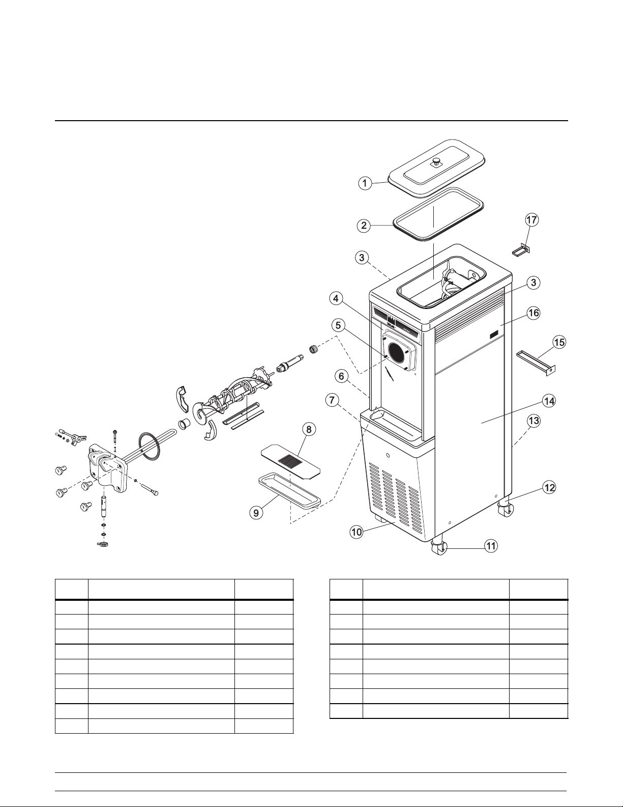
Section 4 Operator Parts I dentification
Model 8751
ITEM DESCRIPTION PART NO.
1 COVER A.-HOPPER X38458
2 GASKET-HOPPER COVER 038375
3 LOUVER-SIDE 017471
4 PANEL·A.-FRONT X33237
5 STUD-NOSE CONE 022822
6 PANEL-UPPER SIDE 024426
7 PANEL A.-SIDE-LOWER-LOUV X39075
8 SHIELD-SPLASH 022763
9 TRAY-DRIP147/8X51/8 013690
ITEM DESCRIPTION PART NO.
10 PANEL -SERVICE 047170
11 CASTER-SWV 018794
12 ADAPTOR·A.-CASTER X18915
13 PANEL- REAR 048203
14 PANEL A. -LOWER SIDE X24424
15 PAN -DRIP 11 5/8 LONG 027503
16 PANEL-UPPER SIDE RIGHT 028823
17 PAN-DRIP *PUMP 048435
4
Models 8751/8754Operator Parts Identification
Page 9

Model 8754
ITEM DESCRIPTION PART NO.
1 COVER A.-HOPPER X38458
2 GASKET-HOPPER COVER 038375
3 PAN-DRIP 17-1/4”LONG 027504
4 PANEL-UPPER SIDE L 028822
5 STUD-NOSE CONE 022822
6 PANEL A.-FRONT X32956
7 PANEL A.-SIDE *LOWER L X46447
8 SHIELD-SPLASH 022766
Models 8751/8754 Operator Parts Identification
ITEM DESCRIPTION PART NO.
9 TRAY-DRIP 014533
10 PANEL- SERVICE 046584
11 CASTER-SWV 018794
12 ADAPTOR A.-CASTER X18915
13 PANEL A. -SIDE-LOWER R X46448
14 PANEL-UPPER SIDE RIGHT 028823
15 LOUVER-SIDE 017471
16 PANEL- REAR 053782
5
Page 10
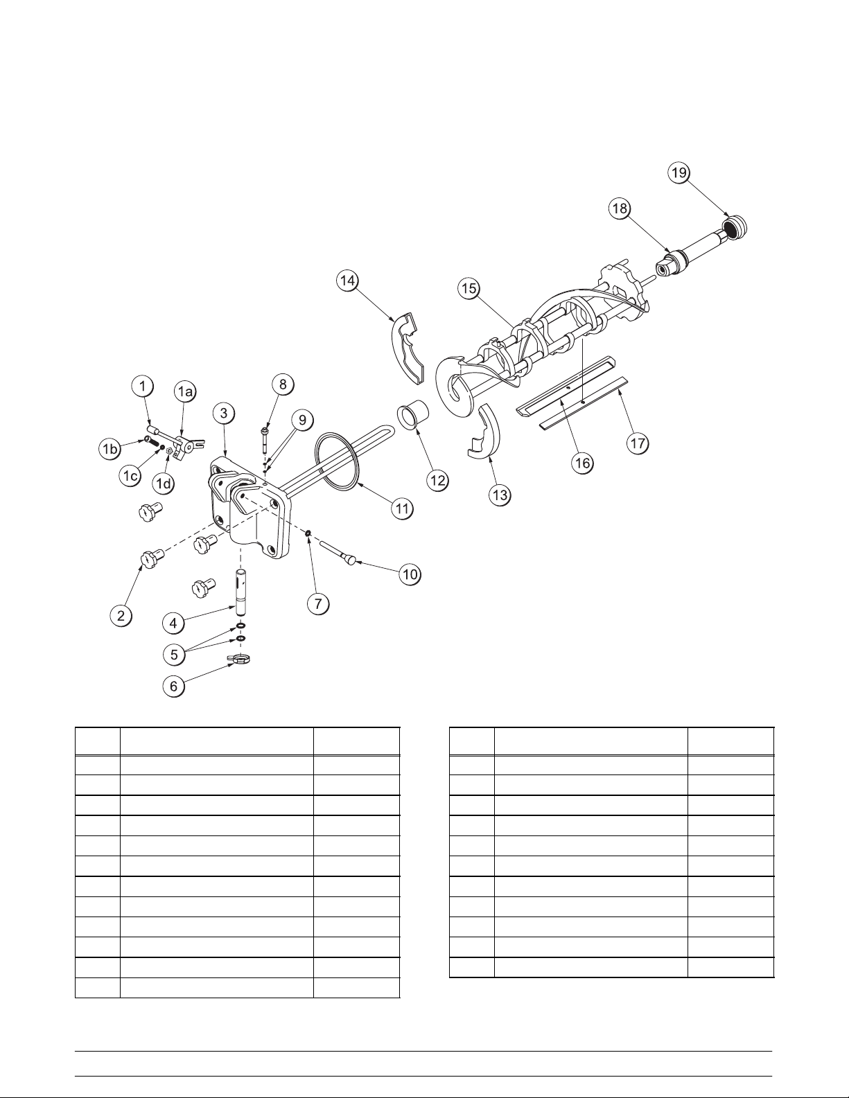
Model 8751 Single Spout Door and Beater Assembly
ITEM DESCRIPTION PART NO.
1 HANDLE A.-DRAW-ADJ. X55096
1a HANDLE-ADJUSTABLE 028804
1b SCREW-ADJUSTMENT 055092
1c O-RING-1/4 OD X .070W 50 015872
1d NUT-JAM 029639-BLK
2 NUT-STUD 021508
3 DOOR A.-1SPOUT *VALOX* X51531-10
4 VALVE A.-DRAW X18303
5 O-RING-7/8 OD X .103W 014402
6 CAP-DESIGN-1.010”ID-6 POINT 014218
7 O-RING-5/16 OD X .070W 016272
8 PLUG-PRIME 028805
ITEM DESCRIPTION PART NO.
9 O-RING-3/8 OD X .070W 016137
10 PIN A.-PIVOT X22820
11 GASKET-DOOR HT 4”-DOUBLE 048926
12 BEARING-FRONT-SHOE 050348
13 SHOE-FRONT HELIX *FRONT* 050347
14 SHOE-FRONT HELIX *REAR* 050346
15 BEATER A.-3.4QT-1 PIN X46231
16 CLIP-SCRAPER·BLADE*7” 046236
17 BLADE-SCRAPER-PLAS.8-1/8 046235
18 SHAFT-BEATER 032564
19 SEAL-DRIVE SHAFT 032560
6
Models 8751/8754Operator Parts Identification
Page 11
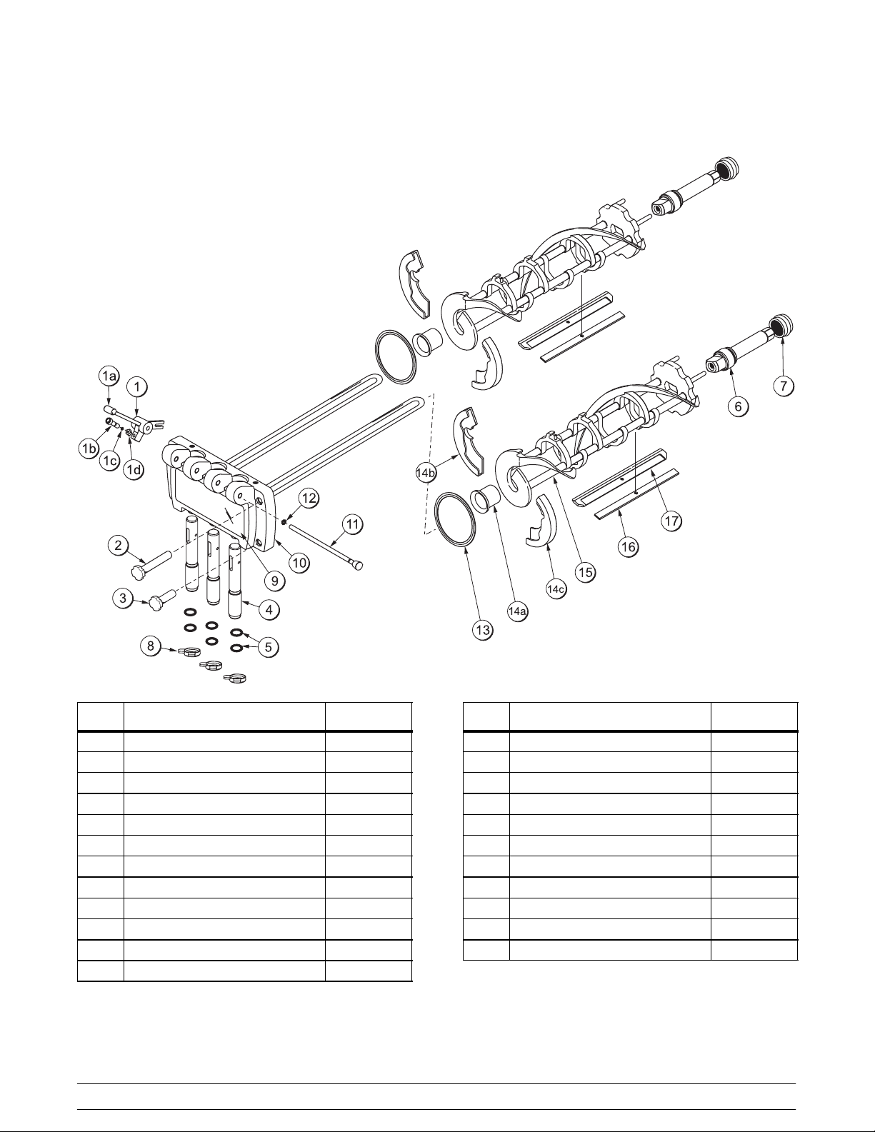
Model 8754 Three Spout Door and Beater Assembly
ITEM DESCRIPTION PART NO.
1 HANDLE A.-DRAW X55096
1a DRAW HANDLE 028804
1b SCREW-ADJUST 055092
1c O-RING 1/4OD X .070W 015872
1d NUT-JAM 029639-BLK
2 NUT-STUD FLAT LONG 034382
3 NUT-STUD FLAT SHORT 034383
4 VALVE A.-DRAW X18303
5 O-RING 7/8OD X .070W 014402
6 SHAFT-BEATER 032564
7 SEAL-DRIVE SHAFT 032560
8 CAP-DESIGN 014218
Models 8751/8754 Operator Parts Identification
ITEM DESCRIPTION PART NO.
9 DECAL-DOOR 021521
10 DOOR A.- 3-SPOUT X51532-12
11 ROD A. - PIVOT X20683
12 O-RING 5/16OD X .070W 016272
13 GASKET-DOOR HT 4” 048926
14a BEARING-FRONT 050348
14b SHOE-FRONT HELIX *REAR* 050346
14c SHOE-FRONT HELIX *FRONT* 050347
15 BEATER A.-3.4QT-1 PIN X46231
16 BLADE-SCRAPER-PLASTIC 046235
17 CLIP-SCRAPER·BLADE*7.00·IN 046236
7
Page 12

Air/Mix Pump
ITEM DESCRIPTION PART NO.
1 TUBE A.--MIX INLET--HOPPER X45318
2 SEAL --AIR INLET FITTING 045327
3 SPRING--TAPERED 1--7/8 022456
4 POPPET --RUBBER BLACK 022473
5 BODY A.--COAX VALVE X46860-B
6 O--RING 2-1/8 OD X .139 W 020051
7 O--RING 1-3/8 OD X .103 W 018664
8 PISTON-- COAX PUMP 045319-B
9 PINA.--COAXPUMPHTSS X36950
10 CLIP--MIX PUMP RETAINER 044641
11 RING--CHECK 2” OD X 1/2 020050
12 SHAFT A.--DRIVE MIX PUMP X39084
ITEM DESCRIPTION PART NO.
12a O-- RING 1/2 ID X .139 W--206 048632
12b O-- RING 1-3/4 OD X .139 W 008904
13 RING-- CHECK 1-1/4 OD X 3/8 033215
14 CYLINDER A.--PUMP HT X44755
15 O--RING 11/16 OD X .103 W--RED 016132
16 PIN--COTTER HAIRPIN 1/8 DIA. 044731
TUBE A.--FEED-- HPR PUMP SS L
(8754)
TUBE A.--FEED-- HPR PUMP SS R
17
(8754)
TUBE A.--HT PUMP FEED SS
(8751)
18 O--RING 3/4 OD X .103 W 015835
8
Models 8751/8754Operator Parts Identification
X44662
X44664
X44666
Page 13
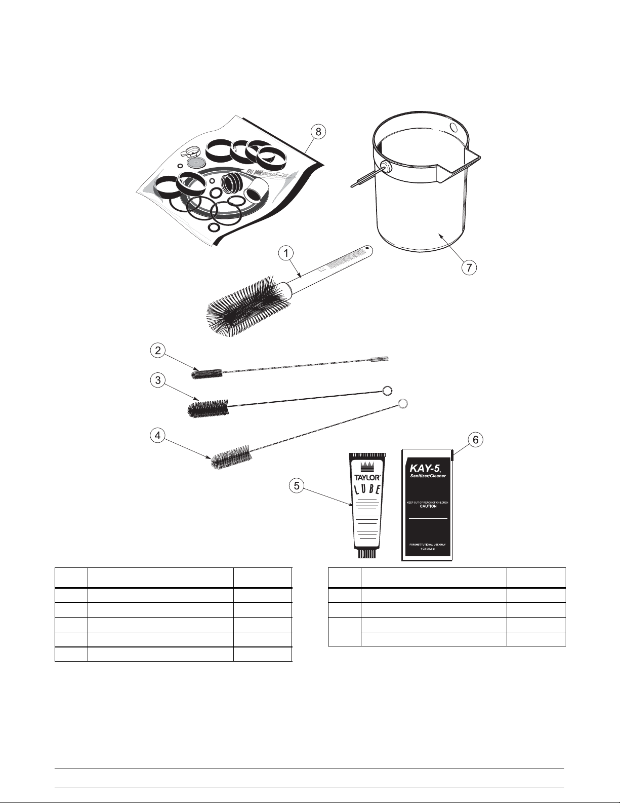
Accessories
ITEM DESCRIPTION PART NO.
1 BRUSH --MIX PUMP BODY 023316
2 BRUSH --DOUBLE ENDED 013072
3 BRUSH --REAR BEARING 013071
4 BRUSH --DRAW VALVE 013073
5 LUBRICANT--TAYLOR 4 OZ. 047518
Models 8751/8754 Operator Parts Identification
ITEM DESCRIPTION PART NO.
6 SANITIZER-- KAY 5 (125 PKTS) 041082
7 PA IL- -MIX 10 Q T. 013163
KIT A.--TUNE UP (MODEL 8751) X49463--9
8
KIT A.--TUNE UP (MODEL 8754) X49463--19
9
Page 14

Section 5 Important: To the Operator
8751
8754
ITEM DESCRIPTION
1 MIX LOW INDICATOR LIGHT
2 MIX REFRIGERATION KEY
3 STANDBY KEY
4 WASH KEY
5 AUTO KEY
ITEM DESCRIPTION
6 PUMP KEY
7 POWER ON/OFF (TOGGLE)
8 RESET BUTTON -- BEATER MOTOR
9 RESET BUTTON -- PUMP
10
Models 8751/8754Important: To the Operator
Page 15
Symbol Definitions
MIX REF Key
To better communicate in the International arena,
symbols have replaced words on many of our operator
switches, function, and fault indicators. Your Taylor
equipment is designed with these International
symbols.
The following chart identifies the symbol definitions.
=OFF
=ON
=MIX
= STANDBY
= WASH
=AUTO
=PUMP
When the MIX REF key is pressed, the light comes on
indicating the mix hopper refrigeration system is
operating. For the Model 8754 the MIX REF is
controlled by the left side of the freezer as viewed from
the operator end. The MIX REF function cannot be
cancelled unless the AUTO or STANDBY modes are
cancelled first.
STANDBY Key
The Separate Hopper Refrigeration System (SHR)
and the Cylinder Temperature Retention System
(CTR) are standard features. The SHR incorporates
the use of a separate small refrigeration system to
maintain the mix in the hopper below 40_(4.4_C) to
assure bacteria control. The CTR works with the SHR
to maintain a good quality product. During long “No
Sale” periods, it is necessary to warm the product in
the freezing cylinder to approximately 35_Fto40_F
(1.7_Cto4.4_C) to prevent overbeating and product
breakdown.
Power Switch
When placed in the ON position, the power switch
allows SOFTECH control panel operation.
Indicator Lights
Located on the front of the machine is a mix level
indicating light. When the light begins to flash, it
indicates that the mix hopper has a low supply of mix
and should be refilled as soon as possible. Always
maintain at least 3” (76 mm) of mix in the hopper. If you
neglect to add mix, a freeze-up may occur. This will
cause eventual damage to the beater, blades, drive
shaft, and freezer door.
To activate the SHR and CTR, press the STANDBY
key. Remove the air orifice and place the air tube (end
without the hole) into the mix inlet hole.
When the STANDBY key is pressed, the light comes
on, indicating the CTR (Cylinder Temperature
Retention System) has been activated. In the
STANDBY mode, the WASH and AUTO functions are
automatically cancelled. The MIX REF function is
automatically locked in to maintain the mix in the
hopper.
To resume normal operation, press the AUTO key.
When the unit cycles off, the product in the freezing
cylinder will be at serving viscosity. At this time, place
the air tube (end with the hole) into the mix inlet hole
and install the air orifice.
Models 8751/8754 Important: To the Operator
11
Page 16
WASH Key
When the WASH key is pressed, the light comes on.
This indicates beater motor operation. The STANDBY
or AUTO modes must be cancelled first to activate the
WASH mode.
If the beater motor is turning properly, press the WASH
key to cancel the cycle. Press the AUTO key to resume
normal operation. If the freezer shuts down again,
contact a service technician. (For the Model 8754
press the AUTO key on both sides of the unit to resume
normal operation.)
AUTO Key
When the AUTO key is pressed, the light comes on.
This indicates that the main refrigeration system has
been activated. In the AUTO mode, the WASH or
STANDBY functions are automatically cancelled. The
MIX REF function is automatically locked in to
maintain the mix in the mix hopper.
Note: An indicating light and an audible tone will
sound whenever a mode of operation has been
pressed. To cancel any function, press the key again.
The light and mode of operation will shut off.
Pump Key
When the PUMP key is pressed, the light comes on,
indicating the air/mix pump will operate as required.
Reset Button
Air/Mix Pump Reset Mechanism
The reset button for the pump is located in the service
panel. The reset protects the pump from an overload
condition. Should an overload occur, the reset
mechanism will trip. To reset the pump, press the reset
button firmly.
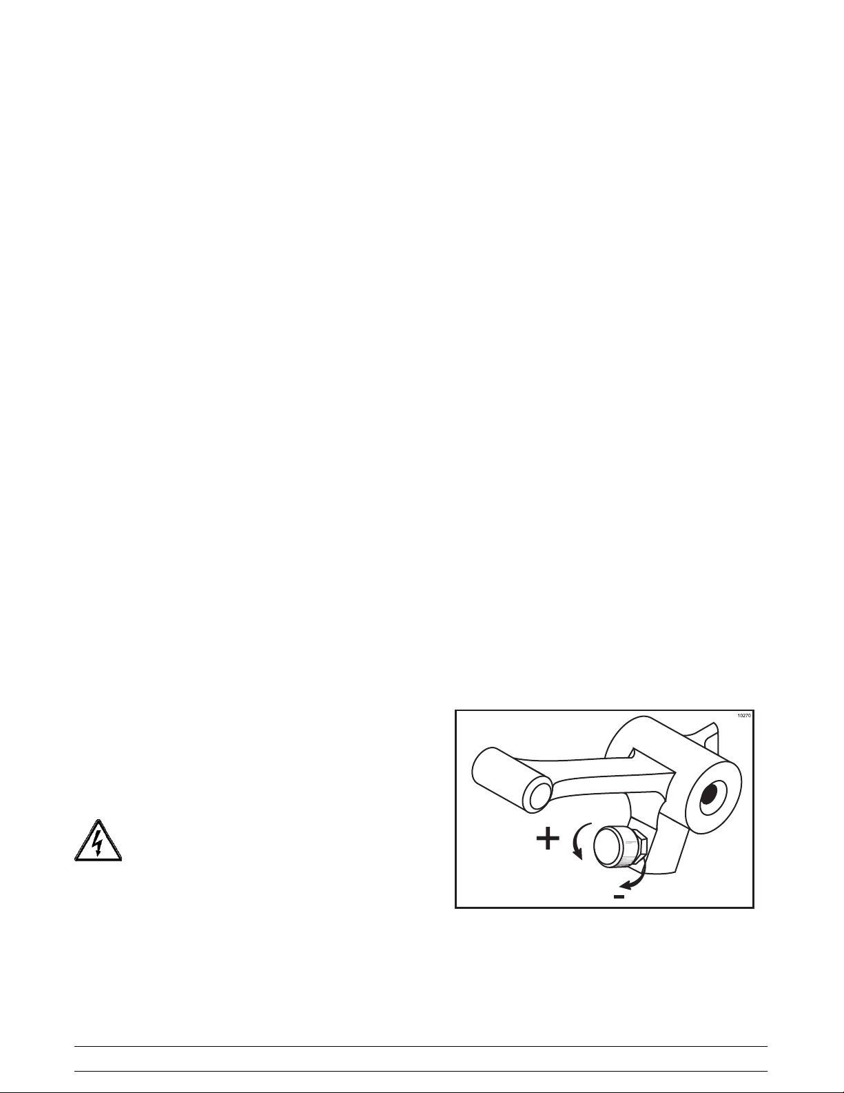
Adjustable Draw Handle
These units feature an adjustable draw handle to
provide the best portion control. The draw handle
should be adjusted to provide a flow rate of 5 to 7-1/2
oz. (148 to 222 ml) of product per 10 seconds. To
INCREASE the flow rate, turn the screw
COUNTERCLOCKWISE. Turn the screw
CLOCKWISE to DECREASE the flow rate. During
“Sanitizing” and “Rinsing”, the flow rate can be
increased by removing the pivot pin and placing the
restrictive bar on the TOP. When drawing product,
always place the restrictive bar on the bottom.
The reset button is located in the service panel on the
front of the machine. The reset protects the beater
motor from an overload condition. If an overload
occurs, the reset mechanism will trip. To properly reset
the freezer, press the AUTO key to cancel the cycle.
Turn the power switch to the OFF position. Press the
reset button firmly.
Do not use metal objects to press the reset
button. Failure to follow this instruction may
result in electrocution.
Turn the power switch to the ON position. Press the
WASH key and observe the freezer’s performance.
Open the side access panel. Make sure the beater
motor is turning the drive shaft in a clockwise direction
(from the operator end) without binding.
Figure 1
IMPORTANT: Once the draw rate is set, tighten the
lock nut with a wrench.
12
Models 8751/8754Important: To the Operator
Page 17

Feed Tube (Back--up Option)
If the air/mix pump has become inoperable because of
a missing or damaged part, the operator can
temporarily operate the unit using the feed tube. The
product ejection rate will be slower when the feed tube
is used instead of the air/mix pump.
Figure 2
ITEM DESCRIPTION PART NO.
1 ORIFICE 022465--100
2 O--RING-- 3/8 OD X .070 W 016137
3 TUBE A.--FEED--SS 5/32 HOLE X29429--2
4 O --RING--.643 OD X .077 W 018572
The feed tube serves two purposes. One end of the
tube has a hole and the other end does not.
1. Normal Operation
During normal operation, the end of the feed tube
with the hole is placed into the mix inlet hole.
Every time the draw handle is raised, new mix and
air from the hopper flow into the freezing cylinder.
This keeps the freezing cylinder properly loaded
and maintains overrun.
2. Long “No Sale” Periods
During long “No Sale” periods, the unit can be
placed into the Standby mode. This maintains
product temperatures below 40_F(4.4_C) in both
the hopper and the freezing cylinder, and helps
prevent overbeating and product breakdown.
To place the unit into the Standby mode, press the
STANDBY key. Remove the air orifice. Lubricate
the o--rings located on the end of the feed tube
without the hole. Place that end of the tube into
the mix inlet hole.This will prevent any mix from
entering the freezing cylinder.
Note: The air orifice is used to meter a certain
amount of air into the freezing cylinder. The air
orifice maintains overrun and allows enough mix
to enter the freezing cylinder after a draw.
050201
Models 8751/8754 Important: To the Operator
13
Page 18

Section 6 Operating Procedures
The Model 8751 has been selected to illustrate the
step-by-step operating procedures for both models
contained in this manual. These models, for all
practical purposes of operation, are the same.
Each unit stores mix in a hopper. The mix is pumped
into the freezing cylinder. They have 3.4 quart (3.2
liter) capacity freezing cylinders and 20 quart (18.9
liter) mix hoppers.
Duplicate the following procedures, where they apply,
for the second freezing cylinder on the Model 8754.
We begin our instructions at the point where we enter
the store in the morning and find the parts
disassembled and laid out to air dry from the previous
night’s cleaning.
These opening procedures will show you how to
assemble these parts into the freezer, sanitize them,
and prime the freezer with fresh mix in preparation to
serve your first portion.
If you are disassembling the machine for the first time
or need information to get to this starting point in our
instructions, turn to page 26, “Disassembly”, and start
there.
Assembly
Fill the inside portion of the seal with 1/4” more
lubricant and lubricate the flat side of the seal that fits
onto the rear shell bearing.
Figure 3
Insert the drive shaft into the freezing cylinder , hex end
first, and into the rear shell bearing until the seal fits
securely over the rear shell bearing. Engage the hex
end firmly into the drive coupling. Be sure the drive
shaft fits into the drive coupling without binding.
Note: When lubricating parts, use an approved food
grade lubricant (example: Taylor Lube).
MAKE SURE POWER SWITCH IS IN THE
“OFF” POSITION! Failure to follow this instruction
may result in severe personal injury from hazardous
moving parts.
Step 1
Install the drive shaft. Lubricate the groove and shaft
portion that comes in contact with the bearing on the
beater drive shaft. Slide the seal over the shaft and
groove until it snaps into place. DO NOT lubricate the
hex end of the drive shaft.
050201
14
Figure 4
Models 8751/8754Operating Procedures
Page 19

Step 2
Install the beater assembly. First check the scraper
blades for any nicks or signs of wear. If any nicks are
present, or if the blades are worn, replace both blades.
If the blades are in good condition, install the scraper
blade clips on the scraper blades. Place the rear
scraper blade over the rear holding pin on the beater.
Note: The hole on the scraper blade must fit securely
over the pin to prevent costly damage.
Figure 5
Repeat steps 1 and 2 for the other side of the freezer
on the Model 8754.
Step 3
Assemble the freezer door. Place the large rubber
gasket(s) into the groove(s) on the back side of the
freezer door.
Slide the white plastic front bearing(s) over the baffle
rod(s) onto the bearing hub(s) making certain that the
flanged end of the bearing is resting against the freezer
door. DO NOT LUBRICATE THE GASKET(S) OR
THE FRONT BEARING(S).
Holding the rear blade on the beater, slide it halfway
into the freezing cylinder. Install the front scraper blade
over the front holding pin.
Install the beater shoes.
Figure 6
Slide the beater assembly the rest of the way into the
freezing cylinder.
Make sure the beater assembly is in position over the
drive shaft. Turn the beater slightly to be certain that
the beater is properly seated. When in position, the
beater will not protrude beyond the front of the freezing
cylinder.
Figure 7
Note: There are two gaskets and two front bearings
for the Model 8754 door, one for each freezing cylinder.
Figure 8
Models 8751/8754 Operating Procedures
15
Page 20

Slide the two o-rings into the grooves on the prime
plug(s). Apply an even coat of Taylor Lube to the
o-rings and shaft(s).
Figure 9
Note: There are two prime plugs for the Model 8754
door, one for each freezing cylinder.
Insert the prime plug(s) into the hole(s) in the top of the
freezer door, and push down.
Figure 11
Step 5
Install the draw valve(s). Slide the two o-rings into
the grooves on the draw valve(s), and lubricate.
Figure 10
Step 4
Install the freezer door. Insert the baffle rod(s)
through the opening in the beater(s) and seat the door
flush with the freezing cylinder. With the door seated
on the freezer studs, install the handscrews. Tighten
equally in a crisscross pattern to insure the door is
snug.
Note: On the Model 8754, the short handscrews go
on the bottom and the long handscrews go on the top.
Figure 12
Note: The Model 8754 has three draw valves.
Lubricate the inside of the freezer door spout(s), top
and bottom, and insert the draw valve(s) from the
bottom until the slot in the draw valve(s) comes into
view.
Figure 13
16
Models 8751/8754Operating Procedures
Page 21

Step 6
Install the adjustable draw handle(s). Slide the o-ring
into the groove on the pivot pin, and lubricate.
Figure 14
Slide the fork over the bar in the slot of the draw valve.
Secure with pivot pin.
Step 7
Snap the design cap(s) over the end of the door
spout(s).
Figure 16
Step 8
Install the front drip tray and the splash shield under
the door spout(s).
Note: The Model 8754 has three draw handles. Slide
the fork of the draw handle in the slot of the draw valve,
starting from the right. Slide the pivot pin through each
draw handle as you insert them into the draw valves.
Figure 15
Note: These units feature adjustable draw handles to
provide the best portion control. The draw handles can
be adjusted for different flow rates. See page 12 for
more information on adjusting these handles.
Figure 17
Step 9
Slide the rear drip pan into the hole in the side panel.
Slide the pump drip pan into the hole in the back panel
(Model 8751 only).
Figure 18
Models 8751/8754 Operating Procedures
17
Page 22

Air/Mix Pump Assembly
The purpose of the air/mix pump is to meter a specific
amount of air and mix, and to transfer this combination
to the freezing cylinder.
Refer to the illustration on page 8 for identification of
parts during assembly.
Step 1
Assemble the piston. Slide the o-ring into the groove
on the piston. DO NOT lubricate this o-ring.
Figure 19
Step 2
Assemble the liquid valve body. Slide the three check
bands and three o-rings into the grooves on the liquid
valve body. DO NOT lubricate the check bands or
o-rings.
Note: Check bands have two smooth surfaces. A
concave shape indicates an incorrect assembly. Turn
the check band inside out to correctly expose the flat
surface.
Figure 21
Step 3
Put a small amount of lubricant on the inside diameter
of the piston. Insert the narrow end of the liquid valve
body into the open end of the piston.
Figure 20
18
Figure 22
Models 8751/8754Operating Procedures
Page 23

Step 4
Apply a small amount of lubricant to the LOWER inside
diameter of the pump cylinder to a depth equivalent to
the length of your index finger. Once applied, the
amount of lubricant should be equal to a paper-thin
film.
Step 5
Assemble the mix inlet tube assembly. Slide the o-ring
and the seal into the grooves on the fittings, and
thoroughly lubricate these parts.
Figure 25
Figure 23
Insert the assembled piston and liquid valve body into
the pump cylinder and push upwards. Align the steel
button at the base of the valve body with the cut-out
groove at the bottom of the pump cylinder.
Figure 24
Note: The hole in the piston must be visible through
the drive hole in the pump cylinder.
Step 6
Put the rubber poppet into the small end of the spring.
Attach the spring and poppet to the end of the pressure
relief fitting. The spring and poppet must be securely
fastened and must not be allowed to float freely.
Figure 26
Note: The rubber poppet and spring act as a pressure
relief valve to prevent a pressure build up in the
freezing cylinder.
Models 8751/8754 Operating Procedures
19
Page 24

Insert the assembled mix inlet tube into the hole in the
base of the liquid valve body.
Figure 27
Secure the pump parts in position by sliding the
retaining pin through the cross holes located at the
bottom of the pump cylinder.
Step 7
Install one o-ring on each end of the mix feed tube.
Thoroughly lubricate.
Figure 29
Step 8
Slide the large o-ring and two small o-rings into the
grooves on the drive shaft. Thoroughly lubricate the
o-rings, and the shaft. DO NOT lubricate the hex end
of the shaft.
Figure 28
Note: When the pump is correctly installed, the head
of the retaining pin should be facing up.
20
Figure 30
Models 8751/8754Operating Procedures
Page 25

Install the hex end of the drive shaft into the drive hub
at the rear wall of the mix hopper.
Figure 31
Note: For ease in installing the pump, position the ball
crank of the drive shaft in the 3 o’clock position.
Step 9
Lay the pump assembly, pump clip, mix feed tube,
locking clip, and gasket in the bottom of the mix hopper
for sanitizing.
Sanitizing
Step 1
Prepare two gallons (7.6 liters) of an approved 100
PPM sanitizing solution (example: Kay-5r). USE
WARM WATER AND FOLLOW THE MANUFACTURER’S SPECIFICATIONS.
Step 2
Pour the two gallons (7.6 liters) of sanitizing solution
over all the parts in the bottom of the mix hopper and
allow it to flow into the freezing cylinder.
Figure 32
Repeat Steps 1 through 9 for the other side of the
freezer on the Model 8754.
Figure 33
Note: You have just sanitized the mix hopper and
parts; therefore, be sure your hands are clean and
sanitized before going on in these instructions.
Step 3
While the solution is flowing into the freezing cylinder,
take particular care to brush-clean the mix level
sensing probe on the front wall and the bottom of the
hopper, the mix hopper, the mix hopper gasket, the mix
inlet hole, the air/mix pump, the pump clip, the mix feed
tube, and the locking clip.
Models 8751/8754 Operating Procedures
21
Page 26

Step 4
Install the pump assembly. To position the pump on the
drive hub at the rear of the mix hopper, align the drive
hole in the piston with the drive crank of the drive shaft.
Secure the pump in place by slipping the pump clip
over the collar of the pump, making sure the clip fits
into the grooves in the collar.
Figure 34
Step 6
Place the power switch in the ON position.
Step 7
Press the WASH key. This will cause the sanitizing
solution in the freezing cylinder to agitate. Allow it to
agitate for five minutes.
Step 5
Push one end of the vinyl sanitizing tube onto the air
inlet tube for the pump. Be sure the free end is
submerged in the sanitizing solution in the hopper.
Figure 35
Repeat steps 1 through 5 for the other side of the
freezer on the Model 8754.
Figure 36
Step 8
With an empty pail beneath the door spout(s), raise the
prime plug and press the PUMP key.
Figure 37
22
Models 8751/8754Operating Procedures
Page 27

Step 9
When a steady stream of sanitizing solution is flowing
from the prime plug opening in the bottom of the
freezer door, pull the draw handle down. Draw off all of
the sanitizing solution. (Note: On the Model 8754,
momentarily pull the center draw handle down to
sanitize the center door spout.)
Step 12
Lubricate the mix feed tube o--rings located on the end
of the tube with the small hole on the side. Stand the
mix feed tube in the corner of the mix hopper. Place the
locking clip in position in the outlet fitting of the pump.
Figure 38
Step 10
Once the sanitizer stops flowing from the door
spout(s), raise the draw handle(s). Press the WASH
and PUMP keys, cancelling the beater motor and
pump operation.
Figure 39
Note: Be sure your hands are clean and sanitized
before continuing these instructions.
Step 11
Remove the vinyl sanitizing tube from the air inlet tube
on the air/mix pump.
Figure 40
Repeat Steps 6 through 12 for the other side of the
freezer on the Model 8754.
Step 13
Assemble the hopper gasket around the top edge of
the mix hopper.
Priming
Step 1
Place an empty pail beneath the door spout and lower
the draw handle. Be sure the prime plug is still in the
UP position. Pour two gallons (7.6 liters) of fresh mix
into the hopper and allow it to flow into the freezing
cylinder. This will force out any remaining sanitizing
solution. When full strength mix is flowing from the
door spout, raise the draw handle.
Note: Use only fresh mix when priming the
freezer.
050201
Models 8751/8754 Operating Procedures
23
Page 28

Step 2
Once a steady stream of mix starts to flow from the
prime plug opening in the bottom of the freezer door,
push down the prime plug.
Step 4
Press the AUTO key. When the unit cycles off, the
product will be at serving viscosity.
Figure 43
Figure 41
Step 3
When the mix stops bubbling down into the freezing
cylinder, insert the mix feed tube. Remove the locking
clip from the outlet fitting of the mix pump. Insert the
outlet end of the mix feed tube into the mix inlet hole
in the mix hopper. Place the inlet end of the mix feed
tube into the outlet fitting of the mix pump. Secure with
locking clip.
Figure 42
Step 5
Fill the hopper with fresh mix. As the mix level comes
in contact with the mix level sensing probe on the front
wall of the hopper, the MIX LOW light will shut off.
Note: The MIX REF light will come on, indicating the
mix refrigeration system is maintaining mix in the mix
hopper.
Step 6
Place the mix hopper cover in position.
Repeat steps 1 through 6 for the other side of the
freezer on the Model 8754.
Closing Procedure
To disassemble your unit, the following items will be
needed:
S Two cleaning pails
S Sanitized stainless steel rerun can with lid
S Necessary brushes (provided with freezer)
S Cleaner
S Single service towels
24
Models 8751/8754Operating Procedures
Page 29

Draining Product From the
Freezing Cylinder
Step 1
Press the AUTO key, cancelling compressor and
beater motor operation.
Press the MIX REF key, cancelling the mix hopper
refrigeration system.
Step 2
Remove the hopper cover and gasket. Take these
parts to the sink for cleaning.
Step 3
With a sanitized pail beneath the door spout, press the
WASH and PUMP keys. Lower the draw handle and
drain the remaining product from the freezing cylinder
and mix hopper.
Rinsing
Step 1
Pour two gallons (7.6 liters) of coolclean water into the
mix hopper. With the brushes provided, scrub the mix
hopper, the mix inlet hole and the mix level sensing
probe.
Step 2
With a pail beneath the door spout, raise the prime plug
and press the WASH key.
Step 3
When a steady stream of rinse water is flowing from
the prime plug opening in the bottom of the freezer
door, lower the draw handle. Drain all the rinse water
from the freezing cylinder. When the water stops
flowing from the door spout, raise the draw handle and
press the WASH key cancelling the WASH mode.
Repeat this procedure until the rinse water being
drawn from the freezing cylinder is clear.
Repeat steps 1 through 3 for the other side of the
freezer on the Model 8754.
Cleaning
Step 4
When the flow of product stops, press the WASH and
PUMP keys and close the draw valve.
Step 5
If local health codes permit, empty the rerun into a
sanitized stainless steel can. Cover the container and
place it in the walk-in cooler.
Step 6
Remove the assembled air/mix pump and take to the
sink for further disassembly and cleaning.
Repeat steps 1 through 6 for the other side of the
freezer on the Model 8754.
ALWAYS FOLLOW LOCAL HEALTH CODES.
Step 1
Prepare two gallons (7.6 liters) of an approved 100
PPM cleaning solution (example: Kay-5r). USE
WARM WATER AND FOLLOW THE MANUFACTURER’S SPECIFICATIONS.
Step 2
Push down the prime plug. Pour the two gallons (7.6
liters) of cleaning solution into the mix hopper.
Step 3
While the solution is flowing into the freezing cylinder,
brush clean the mix hopper, mix level sensing probes
and the mix inlet hole.
Step 4
Press the WASH key. This will cause the cleaning
solution in the freezing cylinder to be agitated.
Step 5
Place an empty pail beneath the door spout and raise
the prime plug.
Step 6
When a steady stream of cleaning solution is flowing
from the prime plug opening in the bottom of the
freezer door, lower the draw handle. Draw off all of the
solution.
Models 8751/8754 Operating Procedures
25
Page 30

Step 7
Once the cleaning solution stops flowing from the door
spout, raise the draw handle and press the WASH key,
cancelling the WASH mode.
Repeat steps 1 through 7 for the other side of the
freezer on the Model 8754.
Disassembly
Step 1
Be sure the power switch is in the OFF position.
Make sure no lights are lit on the control panel.
Step 2
Remove the handscrews, freezer door(s), beater(s),
beater shoes, scraper blades, and drive shaft(s) from
the freezing cylinder(s). Take these parts to the sink for
cleaning.
Step 3
Remove the drive shaft(s) from the drive hub(s) in the
rear wall of the mix hopper(s).
direction until the o-ring pops out of its groove. With the
other hand, push the top of the o-ring forward and it will
roll out of the groove and can be easily removed. If
there is more than one o-ring to be removed, always
remove the rear o-ring first. This will allow the o-ring to
slide over the forward rings without falling into the open
grooves.
Step 4
Remove the retaining pin(s), liquid valve body(ies),
piston(s), mix inlet tube(s), spring(s) and poppet(s).
Remove all o-rings, seal(s), and check bands.
Step 5
Return to the freezer with a small amount of cleaning
solution. With the black bristle brush, brush clean the
rear shell bearing(s) at the back of the freezing
cylinder(s). Brush clean the drive hub opening(s) in the
rear wall of the mix hopper(s).
Step 4
Remove the front drip tray and the splash shield.
Brush Cleaning
Step 1
Prepare a sink with an approved cleaning solution (example: Kay-5r). USE WARM WATER AND FOLLOW
THE MANUFACTURER’S SPECIFICATIONS. If
another approved cleaner is used, dilute according to
label instructions.
IMPORTANT: Follow label directions, as too
STRONG of a solution can cause parts damage, while
too MILD of a solution will not provide adequate
cleaning. Make sure all brushes provided with the
freezer are available for brush cleaning.
Step 2
Remove the seal(s) from the drive shaft(s).
Step 3
From the freezer door(s) remove the gasket(s), front
bearing(s), pivot pin, adjustable draw handle(s), draw
valve(s), prime plug(s), and design cap(s). Remove all
o-rings.
Figure 44
Step 6
Remove the rear drip pan(s) from the side panel and
take it to the sink for cleaning.
Note: If the drip pan is filled with an excessive amount
of mix, refer to the Troubleshooting Guide.
Step 7
Thoroughly brush clean all disassembled parts in the
cleaning solution, making sure all lubricant and mix film
is removed. Take particular care to brush clean the
draw valve core(s) in the freezer door. Place all
cleaned parts on a clean, dry surface to air dry
overnight.
Note: To remove the o-rings, use a single service
towel to grasp the o-ring. Apply pressure in an upward
Step 8
Wipe clean all exterior surfaces of the freezer.
26
Models 8751/8754Operating Procedures
Page 31

Section 7 Important: Operator Checklist
During Cleaning and Sanitizing
Cleaning and sanitizing schedules are governed by
your State or local regulatory agencies and must be
followed accordingly. The following check points
should be stressed during the cleaning and sanitizing
operations.
WE RECOMMEND DAILY CLEANING AND
SANITIZING.
ALWAYS FOLLOW LOCAL HEALTH CODES.
T roubleshooting Bacterial Count
j 1. Thoroughly clean and sanitize machine
regularly, including complete disassembly and
brush cleaning.
j 2. Use all brushes supplied for thorough cleaning.
The brushes are specially designed to reach all
mix passageways.
j 3. Use the white bristle brush to clean the mix inlet
hole which extends from the mix hopper down
to the rear of the freezing cylinder.
j 4. Use the black bristle brush to thoroughly clean
the rear shell bearing located at the rear of the
freezing cylinder. Be sure to have a generous
amount of cleaning solution on the brush.
j 5. IF LOCAL HEALTH CODES PERMIT THE
USE OF RERUN, make sure the mix rerun is
stored in a sanitized, covered stainless steel
container and used the following day. DO NOT
prime the machine with rerun. When using
rerun, skim off the foam and discard. Mix the
rerun with fresh mix in a ratio of 50/50 during the
days operation.
j 7. Properly prepare the cleaning and sanitizing
solutions. Read and follow label directions
carefully. Too strong of a solution may damage
the parts and too weak of a solution will not do
an adequate job of cleaning or sanitizing.
j 8. The temperature of the mix in the mix hopper
and walk-in cooler should be below 40_ F.
(4.4_C.).
Regular Maintenance Checks
j 1. Replace scraper blades that are nicked or
damaged. Before installing the beater
assembly, be certain that scraper blades are
properly attached to the helix.
j 2. Check the rear shell bearing for signs of wear
(excessive mix leakage in rear drip pan) and be
certain it is properly cleaned.
j 3. Using a screwdriver and cloth towel, keep the
rear shell bearing and the female hex drive
socket clean and free of lubricant and mix
deposits.
j 4. Dispose of o-rings and seals if they are worn,
torn, or fit too loosely, and replace with new
ones.
j 5. Follow all lubricating procedures as outlined in
“Assembly”.
j 6. If your machine is air cooled, check the
condensers for accumulation of dirt and lint.
Dirty condensers will reduce the efficiency and
capacity of the machine. Condensers should be
cleaned monthly with a soft brush. Never use
screwdrivers or other metal probes to clean
between the fins.
Note: For machines equipped with an air filter,
it will be necessary to vacuum clean the filters
on a monthly schedule.
j 6. On a designated day of the week, run the mix as
low as feasible and discard it after closing. This
will break the rerun cycle and reduce the
possibility of high bacteria and coliform counts.
Models 8751/8754 Important: Operator Checklist
27
electrical power prior to cleaning the
condenser. Failure to follow this instruction
may result in electrocution.
Caution: Always disconnect
051215
Page 32

j 7. If your machine is equipped with an auxiliary
refrigeration system, check the auxiliary
condenser for accumulation of dirt and lint. Dirty
condensers will reduce the refrigeration
capacity of the mix hopper. Condensers must
be cleaned monthly with a soft brush. Never
use screwdrivers or other metal probes to clean
between the fins.
Winter Storage
If the place of business is to be closed during the winter
months, it is important to protect the freezer by
following certain precautions, particularly if the
building is subject to freezing conditions.
Caution: Always disconnect
electrical power prior to cleaning the
condenser. Failure to follow this instruction
may result in electrocution.
j 8. If your machine is water cooled, check the water
lines for kinks or leaks. Kinks can occur when
the machine is moved back and forth for
cleaning or maintenance purposes.
Deteriorated or cracked water lines should be
replaced only by an authorized Taylor
distributor.
The Air/Mix Pump Checklist
j 1. Dispose of o-rings and check bands if they are
worn, torn or fit too loosely. Replace them with
new ones.
j 2. Follow lubricating procedures carefully . Do not
lubricate check bands.
j 3. Handle plastic pump parts with care to avoid
nicks and cracks.
j 4. Be sure the air/mix pump is properly attached to
the drive hub, or severe and costly damage may
occur.
Disconnect the freezer from the main power source to
prevent possible electrical damage.
On water cooled freezers, disconnect the water
supply. Relieve pressure on the spring in the water
valve. Use air pressure on the outlet side to blow out
any water remaining in the condenser, and then add a
liberal amount of permanent type auto anti-freeze.
This is extremely important. Failure to follow this
procedure may cause severe and costly damage to the
refrigeration system.
Your local Taylor Distributor can perform this winter
storage service for you.
Wrap detachable parts of the freezer such as beater,
blades, drive shaft, and freezer door, and place them
in a protected dry place. Rubber trim parts and gaskets
can be protected by wrapping them with
moisture-proof paper. All parts should be thoroughly
cleaned of dried mix or lubrication which attract mice
and other vermin.
28
Models 8751/8754Important: Operator Checklist
Page 33

Section 8 Troubleshooting Guide
PROBLEM PROBABLE CAUSE REMEDY PA G E
REF.
1. No product is being
dispensed with draw valve
open and the machine in
the AUTO mode.
2. The product is too stiff. a. The viscosity needs
3. The product is too soft. a. Viscosity needs
4. The mix in the mix hopper
is too cold.
a. Freeze-up in mix inlet
hole.
b. Beater motor out on reset. b. Reset the freezer.
c. The beater is rotating
counterclockwise from the
operator end.
d. The circuit breaker is off
or the fuse is blown.
e. There is inadequate mix in
the mix hopper.
adjustment.
adjustment.
b. Not enough air space
around unit. (Air cooled
units)
c. Worn scraper blades. c. Replace regularly.
d. Dirty condenser (A/C) d. Clean monthly.
e. Mix is out of date. e. Use only fresh mix.
f. Loss of water. (W/C) f. Locate cause of water
a. The temperature is out of
adjustment.
a. Call service technician to
adjust the mix hopper
temperature.
c. Contact service technician
to correct rotation to
clockwise from operator
end.
d. Turn the breaker on, or
replace the fuse.
e. Fill the mix hopper with
mix.
a. Contact service
technician.
a. Contact service
technician.
b. Allow for adequate air flow
across the condenser.
loss and correct.
a. Call service technician to
adjust the mix hopper
temperature.
-- -- --
12
-- -- --
-- -- --
24
-- -- --
-- -- --
1
33
27
-- -- --
28
-- -- --
Models 8751/8754 Troubleshooting Guide
29
Page 34

PROBLEM PROBABLE CAUSE REMEDY PA G E
5. The mix in the mix hopper
is too warm.
6. The drive shaft is stuck in
the drive coupling.
7. The freezing cylinder walls
are scored.
8. Excessive mix leakage
into the rear drip pan.
9. Excessive mix leakage
from door spout.
10. No freezer operation after
pressing the AUTO key.
a. The temperature is out of
adjustment.
a. Call service technician to
adjust the mix hopper
temperature.
b. Missing or defective mix
hopper gasket.
c. The mix hopper cover is
not in position.
d. The MIX REF light is not
b. Replace/install the gasket
around the mix hopper.
c. Place the cover in
position.
d. Press the MIX REF key.
lit.
a. Rounded corners of drive
shaft, coupling, or both.
a. Call service technician to
correct cause, and to
replace the necessary
components. Do not
lubricate the hex end of
the drive shaft.
b. Mix and lubricant collected
in the drive coupling.
a. The beater assembly is
bent.
b. Brush clean the rear shell
bearing area regularly.
a. Call service technician to
repair or replace the
beater and to correct the
cause of insufficient mix
in the freezing cylinder.
b. The front bearing is
missing or worn on the
b. Install or replace the front
bearing.
freezer door.
a. Missing or worn drive
a. Install or replace regularly.
shaft seal on drive shaft.
b. The rear shell bearing is
worn.
a. Missing or worn draw
b. Call service technician to
replace rear shell bearing.
a. Install or replace regularly.
valve o-rings.
b. Inadequate lubrication of
b. Lubricate properly.
draw valve o-rings.
c. Wrong type of lubricant is
being used (example:
c. Use the proper lubricant
(example: Taylor Lube).
petroleum base lubricant).
a. Unit is unplugged. a. Plug into wall receptacle.
b. The circuit breaker is off
or the fuse is blown.
c. The beater motor is out on
b. Turn the breaker on, or
replace the fuse.
c. Reset the freezer.
reset.
REF.
-- -- --
23
24
11
-- -- --
26
-- -- --
15
14 / 33
-- -- --
16 / 33
16
14
-- -- --
-- -- --
12
30
Models 8751/8754Troubleshooting Guide
Page 35

PROBLEM PROBABLE CAUSE REMEDY PA G E
1 1. Product is not feeding into
the freezing cylinder.
12. The air/mix pump will not
operate when the PUMP
keyispressed.
13. The air/mix pump will not
operate when the draw
valve is opened and the
unit is in the AUTO mode.
a. Inadequate level of mix in
the mix hopper.
b. The mix inlet hole is
frozen up.
a. Fill the mix hopper with
mix.
b. The mix hopper
temperature needs
adjustment. Call service
technician.
a. The circuit breaker is off. a. Check the breaker.
b. The power cord is
b. Plug in the power cord.
unplugged.
c. The freezer is out on
c. Reset the freezer.
reset.
d. The pump motor is out on
reset.
d. Press the PUMP key to
cancel pump operation.
Press the reset button on
the side of the pump
motor reducer. Press the
PUMP key to continue
pump operation.
a. The pump motor is out on
reset.
a. Press the AUTO key to
cancel the pump
operation. Press the reset
button on the side of the
pump motor reducer.
Press the AUTO key to
continue automatic
operation.
b. The relay is
malfunctioning.
b. Contact service
technician.
REF.
24
-- -- --
-- -- --
-- -- --
12
-- -- --
-- -- --
-- -- --
Models 8751/8754 Troubleshooting Guide
31
Page 36

PROBLEM PROBABLE CAUSE REMEDY PA G E
14. The piston travels back
and forth, but product is
not being pumped.
15. Excessive pump cylinder
wear.
16. Pitting occurring inside the
pump cylinder.
17. The ball crank of the
motor reducer is broken.
18. Too much pressure in the
freezing cylinder.
19. Not enough pressure in
the freezing cylinder.
a. Inspect the check bands. a. Check bands must be
installed correctly, fit
tightly, and not have any
holes or lubrication. Make
sure check bands are not
inside-out.
b. Inspect the o-rings. b. O-rings must not be worn,
torn, or fit too loosely.
c. Check the pump cylinder. c. The piston and liquid valve
body must be assembled
correctly and fit snugly in
the pump cylinder.
d. Missing or defective
d. Replace.
spring or poppet.
a. Inadequate or incorrect
lubrication of pump
a. Follow lubrication
procedures carefully.
cylinder.
b. Incorrect ball crank
rotation.
a. Cleaner was left inside the
pump cylinder.
b. Contact service
technician.
a. After brush cleaning the
pump cylinder, allow it to
air dry. Follow
disassembly procedures
carefully.
a. Incorrect rotation of pump
motor.
a. Plugged relief hole in
a. Contact service
technician.
a. Clean.
liquid valve body below
poppet.
a. Weak or bent spring in
a. Replace.
liquid valve body.
b. Malfunctioning draw
switch.
b. Contact service
technician.
c. Missing poppet. c. Install the poppet.
REF.
-- -- --
27
18
19
19
-- -- --
26
-- -- --
-- -- --
-- -- --
-- -- --
19
32
Models 8751/8754Troubleshooting Guide
Page 37

Section 9 Parts Replacement Schedule
PART DESCRIPTION EVERY
3MONTHS
Drive Shaft Seal X
Scraper Blade X
Freezer Door Gasket X
Front Bearing X
Beater Shoes X
Draw Valve O-Ring X
Pivot Pin O-Ring X
Prime Plug O-Ring X
Air Tube O-Ring X
Air Orifice O-Ring X
White Bristle Brush, 3” x 7” Inspect & Replace
White Bristle Brush, 1” x 2” Inspect & Replace
Black Bristle Brush, 1” x 2” Inspect & Replace
EVERY
6MONTHS
if Necessary
if Necessary
if Necessary
ANNUALLY
Minimum
Minimum
Minimum
Double-Ended Brush Inspect & Replace
if Necessary
Refer to Parts List on the next page when ordering the above parts.
Minimum
Models 8751/8754 Parts Replacement Schedule
33
Page 38

Section 10 Parts List
144
144
UPDATE
REMARKS PARTS
8751--J9036440/UP-- 3PH,
WARR.
CLASS
8754
QTY.
J9053627/UP--1PH
J9053627-- 1PH
HP62 Refrigerant: 8751 - J6080596, 8754 - J6080465/Up
8751
QTY.
NUMBER
DESCRIPTION PART
ADAPTOR A.--CASTER X18915 4 4 103
BEARING--FRONT 050348 1 2 000
SHOE--FRONT HELIX--REAR 050346 1 2 000
SHOE--FRONT HELIX--FRONT 050347 1 2 000
BEARING--REAR SHELL 031324 1 2 000
+GUIDE--DRIP SEAL 028992 1 2 000
+NUT--BRASS BEARING 028991 1 2 000
+WASHER--BEARING LOCK 012864 1 2 000
BEATER ASSEMBLY X46231 1 2 103
+BLADE--SCRAPER 046235 2 4 000
+CLIP--SCRAPER BLADE 046236 2 4 103
PIN--SCRAPER BLADE 014170 2 4 000
BELT--AX35 022848 2 4 000
BLOCK--TERMINAL--2 P 039422 1 2 103 SINGLE PHASE
SCREW--TERMINAL BLOCK 039420 2 4 000
BLOCK--TERMINAL--3 P 039423 1 2 103 THREE PHASE
BLOWER ASSEMBLY X53725--27 1 103
MOTOR-- BLOWER 053481--27 1 103
BOOT--CAPACITOR 031314 1 1 000
CAPACITOR--RUN 033047 1 1 103
CLIP--SCREEN BLOWER 053730 4 4 103
HOUSING--BLOWER 053727 1 1 103
MOTOR-- BLOWER 053480--27 1 1 103
SCREEN--BLOWER 053729 1 1 103
WHEEL--BLOWER 053726 1 1 103
BLOWER ASSEMBLY X53478--27 1 1 103 8751--PRIOR TO J9036440--3PH,
BOARD--LOGIC X42002SER1 1 2 212
FUSE--SLO BLO 051272 1 2 103
BOARD--POWER X32326-- SER 1 2 212
+ Available Separately
Parts List Models 8751/8754
34
Page 39

UPDATE
REMARKSWARR.
CLASS
8754
QTY.
141/142
8754--J9036611/UP,
144
8751--J9053627/UP-- 1PH
141
8754--PRIOR TO J9036611,
144
8751--PRIOR TO J9036440-- 3ph 60hz,
8751--PRIOR TO J9053627-- 1ph 60hz
8751
QTY.
PART
NUMBER
DESCRIPTION PARTS
BRUSH--BLACK (1” X 2”) 013071 1 1 000
BRUSH--DOUBLE END 013072 1 1 000
BRUSH--WHITE (1” X 2”) 013073 1 1 000
BRUSH--WHITE (3” X 7”) 023316 1 1 000
CABLE--RIBBON 032445 1 2 103
CAP--DESIGN 014218 1 3 000
CAPACITOR--RUN 029439 1 2 103 230--60-- 1
CAPACITOR--START 031304 1 2 103 230--60-- 1
RELAY--START 052401--27 1 2 103 230-- 60-- 1
CAPACITOR--START 037251-- 1 2 103 PUMP
CASTER--SWIVEL 018794 4 4 103
COMPRESSOR-- COPELAND 052397--33 1 512 8751-- J9036440/UP--3PH 144
COMPRESSOR-- COPELAND 052397-- 1 2 512
COMPRESSOR -- BRISTOL 048259-- 1 2 512
CAPACITOR--RUN 012906 1 2 103 230--60-- 1
CAPACITOR--START 031790 1 2 103 230--60-- 1
RELAY--START 038145 1 2 103 230-- 60-- 1
CAPACITOR--START 047703 1 1 103
RELAY--START 047702--27 1 1 103
COMPRESSOR--AUXILIARY 047701--27 1 1 512
COVER--TERMINAL 047739 1 1 103
CONDENSER-- AUXILIARY 027155 1 1 103
CONDENSER--MAIN 048233 1 2 103
COUPLING--DRIVE 012721 1 2 103
COVER A.--MIX HOPPER X38458--SER 1 2 103
+GASKET--MIX HOPPER 038375 1 000
+GASKET--MIX HOPPER 038474 1 000
KNOB--MIX HOPPER 025429 1 2 103
DECAL--CLEAN AND SANITIZE 042170 1 1 000
+ Available Separately
Models 8751/8754 Parts List
35
Page 40

UPDATE
REMARKSWARR.
CLASS
8754
QTY.
8751
QTY.
PART
NUMBER
DESCRIPTION PARTS
DECAL--DECORATIVE 033231 1 000
DECAL--DECORATIVE 033232 1 000
DECAL--POWER SWITCH -- ON/OFF (OLD) 032484 1 000 PRIOR TO J8080000 (NEW -- SEE LABEL) 132
DECAL--POWER SWITCH -- ON/OFF 032484 1 000
DECAL--TROUBLESHOOTING 038374 1 1 000
DEFLECTOR--BLOWER EXHAUST 046586 1 1 103
DIAGRAM--WIRING (NEW) 052613-- 1 000 W/COPELAND 136/144
DIAGRAM--WIRING (OLD) 050318-- 1 000 PRIOR TO COPELAND 136/144
DIAGRAM--WIRING 046585-- 1 000
DOOR A.--FREEZER X51531-- 10 1 103
+BEARING--FRONT 050216 1 000
+CAP--DESIGN 014218 1 000
+GASKET--D OOR 048926 1 000
DOOR A.--FREEZER X51532-- 12 1 103
+BEARING--FRONT 050216 2 000
+CAP--DESIGN 014218 3 000
DECAL--DOOR 021521 1 000
+GASKET--D OOR 048926 2 000
HANDLE--DRAW 028804 1 103
SCREW--ADJUSTABLE 026592 1 000 PLASTIC
O--RING 015872 1 000
HANDLE--DRAW 028804 3 103
SCREW--ADJUSTABLE 033662 3 103 STAINLESS 121
O--RING 015872 3 000
DRYER--CAPILLARY 047699 1 1 000 AUXILIARY
DRYER--FILTER 048901 1 2 000
GASKET--HOPPER 038375 1 2 000
GEAR--REDUCER 021286--SER 1 2 212
GUIDEA.--DRIPPAN X28863 1 103
GUIDEA.--DRIPPAN X28699 1 103
GUIDEA.--DRIPPAN--PUMP X48433 1 103 HOPPER PUMP
HANDLE A.--ADJ USTABLE DRAW X26996 1 103
HANDLE A.--ADJ USTABLE DRAW X33687 3 103 J7090000/UP (REPLACES X26996) 121
+ Available Separately
Parts List Models 8751/8754
36
Page 41

UPDATE
REMARKSWARR.
CLASS
8754
QTY.
8751
QTY.
PART
NUMBER
DESCRIPTION PARTS
HOOD X41996 1 103
HOOD 013667 1 103
KIT A.--TUNE--UP X49463--9 1 000
BAND--CHECK (LIQUID VALVE BODY) 020050 2 000
BAND--CHECK (LIQUID VALVE BODY) 033215 1 000
BEARING--FRONT (FREEZER DOOR) 050348 1 000
SHOE--FRONT HELIX--REAR 050346 1 000
SHOE--FRONT HELIX--FRONT 050347 1 000
CAP--DESIGN (FREEZER DOOR) 014218 1 000
GASKET--DOOR 048926 1 000
O--RING (PRIME PLUG) 016137 3 000
O--RING (DRAW VALVE) 014402 2 000
O--RING (PUMP DRIVE SHAFT) 008904 1 000
O--RING (LIQUID VALVE BODY) 018664 1 000
O--RING (LIQUID VALVE BODY & PISTON) 020051 3 000
O--RING (MIX INLET TUBE) 015835 1 000
O--RING (MIX FEED TUBE) 016132 2 000
O--RING (PIVOT PIN) 016272 1 000
POPPET--RUBBER 022473 1 000
SEAL (AIR INLET FITTING) 045327 1 000
SEAL (BEATER DRIVE SHAFT) 032560 1 000
O--RING (PUMP DRIVE SHAFT) 048632 2 000
SPRING 022456 1 000
KIT A.--TUNE--UP X49463--19 1 000
BAND--CHECK (LIQUID VALVE BODY) 020050 4 000
BAND--CHECK (LIQUID VALVE BODY) 033215 2 000
BEARING--FRONT (FREEZER DOOR) 050348 2 000
CAP--DESIGN (FREEZER DOOR) 014218 3 000
GASKET--DOOR 048926 2 000
O--RING (PRIME PLUG) 016137 4 000
O--RING (DRAW VALVE) 014402 7 000
O--RING (DRIVE CRANK) 008904 2 000
O--RING (LIQUID VALVE BODY) 018664 2 000
+ Available Separately
Models 8751/8754 Parts List
37
Page 42

UPDATE
REMARKSWARR.
CLASS
8754
QTY.
8751
QTY.
PART
NUMBER
DESCRIPTION PARTS
O--RING (LIQUID VALVE BODY & PISTON) 020051 6 000
O--RING (MIX INLET TUBE) 015835 2 000
O--RING (MIX FEED TUBE) 016132 4 000
O--RING (PIVOT PIN) 016272 1 000
O--RING (PUMP DRIVE SHAFT) 048632 4 000
POPPET--RUBBER 022473 2 000
SEAL--DRAW VALVE 034698 1 000
SEAL (AIR INLET FITTING) 045327 2 000
SEAL (BEATER DRIVE SHAFT) 032560 2 000
SHOE--FRONT HELIX--REAR 050346 2 000
SHOE--FRONT HELIX--FRONT 050347 2 000
SPRING 022456 2 000
TOOL--O--RING REMOVAL 048260--WHT 1 000
LABEL--DOOR--WARN--MOVE PARTS 032749 1 1 000
LABEL--SWITCH--POWER--OFF/ON SYMBOLS 052632 1 000 ON POSITION -- RIGHT SIDE 132/142
LABEL--WARN--COVER 051433 5 6 000
LOUVER--SIDE 017471 1 103 RIGHT
CAPACITOR--RUN (230--60--1) 027087 1 2 103 MAGNETEK/CENTURY 230--30--1
CAPACITOR--RUN (230--60--1) 036084 1 2 103 LEESON 230--30--1
CAPACITOR-- START (230-- 60--1) 028315 1 2 103 MAGNETEK/CENTURY 230--30--1
CAPACITOR-- START (230-- 60--1) 045862 1 2 103 LEESON 230--30--1
+BLADE-- FAN 033499 1 1 103 SHR
+OVERLOAD 044464 1 2 103
LOUVER--SIDE 028288 1 103 LEFT
LOUVER--SIDE 017471 2 2 103
LUBRICANT--T AYLOR 4 OZ. 047518 1 1 000
MAN--OPER 028754--M 1 1 000
MOTOR--BEATER 021522-- 1 2 212
MOTOR-- FAN (w/BLADE) 027309-- 1 1 103 SHR
MOTOR--REDUCER 036955--34 1 2 103
NUT--JAM--5/16--24 029639-- BLK 3 000 J7090000/UP 121
NUT--STUD (HANDSCREW) 021508 4 103 HANDSCREW
NUT--STUD (LONG) 034382 2 103 LONG
+ Available Separately
Parts List Models 8751/8754
38
Page 43

UPDATE
REMARKSWARR.
CLASS
8754
QTY.
8751
QTY.
PART
NUMBER
DESCRIPTION PARTS
O--RING 016137 1 2 000
NUT--STUD (SHORT) 034383 2 103 SHORT
ORIFICE-- AIR 022465--100 1 2 103
PAIL 013163 1 1 000 10 QT. / 9.5 LITER
PAN--DRIP 048435 1 103 HOPPER PUMP
PAN A.--DRIP X38198 1 103 HOPPER PUMP
PAN--DRIP -- 11--5/8” LONG 027503 1 103
PAN--DRIP 17--1/4” LONG 027504 1 103
PANEL--REAR 048203 1 103
PANEL--REAR 017563 1 103
PANEL--SERVICE 047170 1 103
PANEL--SERVICE 046584 1 103
PANEL--UPPER RIGHT SIDE 028823 1 1 103
PANEL-- LOWER RIGHT SIDE X24424--SER 1 103
PANEL A.--LOWER SIDE--LOUVERED--LEFT X39075--SER 1 103
PANEL--UPPER SIDE 024426 1 103
PANEL--UPPER SIDE--LEFT 028822 1 103
PANEL A.--LOWER SIDE-- LEFT X46447--SER 1 103
PANEL A.--LOWER SIDE--RIGHT X46448-- SER 1 103
PANEL A.--FRONT X33237 1 103
PANEL A.--FRONT X32956 1 103
PIN A.--PIVOT X22820 1 103
+O--RING 016272 1 000
PIN A.--PIVOT X20683 1 103
+O--RING 016272 1 000
PLATE--DECORATIVE 033239 1 103
PLATE--DECORATIVE 032961 1 103
PLUG--DRIP TRAY HOLE 029595 1 000
PLUG--PRIME 028805 1 2 103
+O--RING 016137 2 4 000
PROBE A.--MIX X30922 1 2 103
+DISC 030965 1 2 103
+SPACER 030966 1 2 103
+ Available Separately
Models 8751/8754 Parts List
39
Page 44

UPDATE
REMARKSWARR.
CLASS
8754
QTY.
8751
QTY.
PART
NUMBER
DESCRIPTION PARTS
PROBE A.--THERMISTOR -- HOPPER X50717 1 1 103
PROBE A.--THERMISTOR -- BARREL X31602 1 2 103
BAND--CHECK (LIQUID VALVE BODY) 020050 2 4 000
BAND--CHECK (LIQUID VALVE BODY) 033215 1 2 000
BODY A.--LIQUID VALVE X46860-- B 1 2 103
PULLEY (BEATER MOTOR) 016403 1 2 103 BEATER MOTOR
PULLEY (GEAR) 027822 1 2 103 GEAR
PUMP A.-- COAXIAL AIR/MIX X45316--B 1 2 103
+CLIP--LOCKING 044731 1 2 103
+CLIP--PUMP 044641 1 2 103
CYLINDER A.--PUMP X44755 1 2 103
O--RING (LIQUID VALVE BODY) 018664 1 2 000
O--RING (LIQUID VALVE BODY & PISTON) 020051 3 6 000
PIN A.--PUMP X36950 1 2 103
PISTON 045319--B 1 2 103
POPPET--RUBBER 022473 1 2 000
SPRING 022456 1 2 000
TUBE A.--MIX INLET X45318 1 2 103
O--RING 015835 1 2 000
SEAL 045327 1 2 000
RELAY--COMPRESSOR 012725-- 1 2 103
RELAY--SPDT--30A--240V (A/C) 032607-- 1 1 103 FOR BLOWER
O--RING (DRIVE CRANK) 008904 1 2 000
O--RING (DRIVE CRANK) 048632 2 4 000
+SEAL--DRIVE SHAFT 032560 1 2 000
RELAY 039725-- 1 2 103 MOTOR REDUCER
SANITIZER--KAY--5 041082 1 1 000
SHAFT A.-- DRIVE X39084 1 2 103
SHAFT--BEATER DRIVE 032564 1 2 103
SHELL A.--INSULATED X50332 1 512
SHELL A.--INSULATED X50376 1 512
+STUD--NOSE CONE 022822 4 4 103
SHIELD--SPLASH 022763 1 103
+ Available Separately
Parts List Models 8751/8754
40
Page 45

UPDATE
REMARKSWARR.
CLASS
8754
QTY.
8751
QTY.
PART
NUMBER
DESCRIPTION PARTS
SHIELD--SPLASH 022766 1 103
SLEEVE A.--MIX PUMP X45012 1 2 103
+NUT--PU MP SLEEVE 036933 1 2 103
STARTER--BEATER LINE 041950-- 1 2 103
OVERLOAD--THERMAL 047150-- 1 2 103
SWITCH--PRESSURE 405 PSI (A/C) -- NEW 052663 1 103 COPELAND 136/142
SWITCH--PRESSURE 440 PSI (A/C) 048230 1 2 103 BRISTOL 136/142
SWITCH--TOGGLE (POWER SWITCH) 024295 1 103
SWITCH--TOGGLE (POWER SWITCH) 037394 1 103
SWITCH A.--DRAW X33322--SER 1 103
ARM A.-- SWITCH X33326 1 103
BRACKET A.--SWITCH X43722 1 103
E--RING 049178 1 000
PIN--PIVOT 015478 1 103
SPRING--LEFT RETURN 041660 1 103
SPRING--RIGHT RETURN 041661 1 103
SWITCH--MICRO 028889 1 103
SWITCH A.--DRAW X38547 1 103
ARM--SWITCH--LEFT 038649 1 103
ARM--SWITCH--RIGHT 038650 1 103
BRACKET A.--SWITCH X38252 1 103
E--RING 032190 4 000
PIN--PIVOT 038484 1 103
ROD--SPRING RETAINER 038254 1 103
SPRING--EXTENSION 038922 2 103
SPRING--LEFT RETURN 038923 1 103
SPRING--RIGHT RETURN 038924 1 103
SWITCH A.--DRAW X39269 1 103
BRACKET--SWITCH 039264 1 103
SWITCH--MICR+A321O 039252 2 103
TRAY--FRONT DRIP 013690 1 103
TRAY--FRONT DRIP 014533 1 103
TRIM--LEFT REAR CORNER 020882 1 103
+ Available Separately
Models 8751/8754 Parts List
41
Page 46

UPDATE
REMARKSWARR.
CLASS
8754
QTY.
8751
QTY.
PART
NUMBER
DESCRIPTION PARTS
TRIM--LEFT REAR CORNER 013761 1 103
TRIM--RIGHT REAR CORNER 020883 1 103
TRIM--RIGHT REAR CORNER 013663 1 103
TUBE A.--MIX FEED X44666 1 103
+O--RING 016132 2 000
TUBE A.--FEED (LEFT) X44662 1 103
TUBE A.--FEED (RIGHT) X44664 1 103
O--RING--FEED TUBE 016132 4 000
VALVE--ACCESS 047016 1 2 103
VALVE--ACCESS 044455 1 2 103
VALVE--ACCESS 043232 1 103
VALVE--ACCESS 044404 1 1 103
VALVE--ACCESS 029406 1 1 103
VALVE--AUTOMATIC EXPANSION 046365 1 2 103
+BOOT--EXPANSION VALVE 050900 1 2 000
VALVE--E.P.R. 022665 1 1 103
+O--RING 014402 2 6 000
VALVE A.--DRAW X18303 1 3 103 J7060000 (REPLACES X45380) 118
VIDEO--TRAINING 047247-- 1 1 000
+ Available Separately
Parts List Models 8751/8754
42
Page 47

UPDATE
REMARKSWARR.
144
141
CLASS
8754
QTY.
8751
QTY.
PART
NUMBER
8754--J9036611/UP 141
8751--PRIOR TO J9053634,
8754--PRIOR TO J9036611
DESCRIPTION PARTS
CAPACITOR-- RUN-- 45UF/370V 052400 1 2 103 230--50-- 1
CAPACITOR-- START--145--175UF/250V 052399 1 2 103 230--50-- 1
RELAY--START COMPRESSOR 052401--27 1 2 103 230-- 50--1
COMPRESSOR (MAIN -- HP62) BRISTOL 048259-- 1 2 512
OPTIONAL FEATURES
WATER COOLED
BLOWER 012796-- 1 1 103
+GUARD--BLOWER 022505 1 1 103
CONDENSER 048287 1 2 103
PANEL A.--LOWER SIDE (R & L) X24424--SER 2 2 103
SWITCH--PRESSURE 048231 1 2 103
VALVE--WAT ER 046686 1 2 103
50 CYCLE
BLOCK--TERMINAL (230--50-- 1) 039421 1 2 103
BLOCK--TERMINAL (220/440--50-- 3) 039424 1 2 103
CAPACITOR--RUN (BEATER MOTOR) 023606 1 2 103 CENTURY/MAGNETEK
CAPACITOR--RUN (BEATER MOTOR) 023739 1 2 103 LEESON
CAPACITOR--START (BEATER MOTOR) 028315 1 2 103 CENTURY/MAGNETEK
CAPACITOR--START (BEATER MOTOR) 026659 1 2 103 LEESON
COMPRESSOR--COPELAND 052397-- 1 2 512 8751--J9053634/UP 144
+ Available Separately
Models 8751/8754 Parts List
43
CAPACITOR--RUN 023739 1 2 103 230--50-- 1
CAPACITOR--START 031790 1 2 103 230--50-- 1
RELAY--START 038146 1 2 103 230-- 50-- 1
PULLEY (BEATER MOTOR) 011545 1 2 103
Page 48

Model 8751
052613-27
Rev . 11/02
Page 49

Model 8751
052613-33
Rev . 11/02
Page 50

Model 8751
052613-40
Rev . 11/02
Page 51

Model 8751
052613-58
Rev . 11/02
Page 52

Model 8754
046585--27
Rev . 11/02
Page 53

Model 8754
046585--33
Rev . 11/02
 Loading...