

Page 1

OPERATOR’S
MANUAL
Model 702 & 772
Navy Soft Serve Freezers
Original Operating Instructions
051469- M
December, 1998 (Original Publication)
(Updated 12/6/13)
Page 2

Complete this page for quick reference when service is required:
Taylor Distributor:
Address:
Phone:
Service:
Parts:
Date of Installation:
Information found on the data label:
Model Number:
Serial Number:
Electrical Specs: Voltage Cycle
Phase
Maximum F use Size: A
Minimum Wire Ampacity: A
E 1998 Carrier Commercial Refrigeration, Inc.
051469- M
Any unauthorized reproduction, disclosure, or distribution of copies by any person of any portion of this work may be
a violation of Copyright Law of the United States of America and other countries, could result in the awarding of Statutory
Damages of up to $250,000 (17 USC 504) for infringement, and may result in further civil and criminal penalties.
All rights reserved.
Taylor Company
a division of Carrier Commercial Refrigeration, Inc.
750 N. Blackhawk Blvd.
Rockton, IL 61072
Page 3

Table of Contents
Section 1 To th e Installer 1............................................
Installer Safety 1........................................................
Site Preparation 1.......................................................
Running Specifications 3.................................................
Section 2 Thermistor Control 5........................................
Section 3 Semi- Assembled Navy Units 8...............................
Disassembly 8..........................................................
Assembly 9............................................................
Semi- Assembled Model 702 Exploded View 11..............................
Section 4 To the Operator 13...........................................
Section 5 Safety 14....................................................
Section 6 Operator Parts Identification 16...............................
Model 702 16............................................................
Model 702 Door Assembly 17.............................................
Model 772 18............................................................
Model 772 Door Assembly 19.............................................
Section 7 Important: To the Operator 20.................................
Indicator Light “Mix Low” 20...............................................
Symbol Definitions 20....................................................
Control Switch 20........................................................
Reset Button 20.........................................................
Thermistor Control 21....................................................
Draw Rate 21............................................................
Optional Features 21.....................................................
Section 8 Operating Procedures 22.....................................
Assembly 22............................................................
Sanitizing 24............................................................
Priming 25..............................................................
Closing Procedure 26....................................................
Draining Product From the Freezing Cylinder 27.............................
Rinsing 27..............................................................
Cleaning 27.............................................................
Disassembly 27..........................................................
Brush Cleaning 28.......................................................
Section 9 Important: Operator Checklist 29..............................
During Cleaning and Sanitizing 29.........................................
Troubleshooting Bacterial Count 29........................................
Regular Maintenance Checks 29...........................................
Winter Storage 30........................................................
Section 10 Troubleshooting Guide 31....................................
Troubleshooting Thermistor Components 34................................
Table of Contents Models 702 & 772
Page 4

Table of Contents - Page 2
Section 11 Parts Replacement Schedule 35...............................
Section 12 Service Parts Functions 36...................................
Section 13 Limited Warranty on Equipment 37............................
Section 14 Limited Warranty on Parts 39.................................
Section 15 Parts List 42.................................................
Wiring Diagrams 48......................................................
Section 16 Motor Characteristics 52......................................
702 - Motor Characteristics and Performance Data 52........................
702 - Controller Data 53..................................................
702 - Motor Characteristics and Performance Data 54........................
702 - Controller Data 55..................................................
702 - Motor Characteristics and Performance Data 56........................
702 - Controller Data 57..................................................
772 - Motor Characteristics and Performance Data 58........................
772 - Controller Data 59..................................................
772 - Motor Characteristics and Performance Data 60........................
772 - Controller Data 61..................................................
772 - Motor Characteristics and Performance Data 62........................
772 - Controller Data 63..................................................
Section 17 Navy Specifications 64.......................................
Note: Continuing research results in steady improvements; therefore, information
in this manual is subject to change without notice.
Note: Only instructions originating from the factory or its authorized translation
representative(s) are considered to be the original set of instructions.
E 1998 Carrier Commercial Refrigeration, Inc. (Original Publication)
(Updated December, 2013)
051469- M
Any unauthorized reproduction, disclosure, or distribution of copies by any person of any portion of this work
may be a violation of Copyright Law of the United States of America and other countries, could result in the
awarding of Statutory Damages of up to $250,000 (17 USC 504) for infringement, and may result in further
civil and criminal penalties.
All rights reserved.
Taylor Company
a division of Carrier Commercial Refrigeration, Inc.
750 N. Blackhawk Blvd.
Rockton, IL 61072
Models 702 & 772
Table of Contents
Page 5
Section 1 To the Installer
The following information has been included in the
manual as safety and regulatory guidelines. For
complete installation instructions, please see the
Installation Checklist.
Installer Safety
In all areas of the world, equipment should
be installed in accordance with existing local codes.
Please contact your local authorities if you have any
questions.
Care should be taken to ensure that all basic safety
practices are followed during the installation and
servicing activities related to the installation and
service of Taylor® equipment.
S Only authorized Taylor service personnel
should perform installation, maintenance,
and repairs on Taylor equipment.
S Authorized service personnel should consult
OSHA Standard 29CFRI910.147 or the
applicable code of the local area for the
industry standards on lockout/tagout
procedures before beginning any installation
or repairs.
S Authorized service personnel must ensure
that the proper protective equipment (PPE)
is available and worn when required during
installation and service.
S Authorized service personnel must remove
all metal jewelry, rings, and watches before
working on electrical equipment.
The main power supply(s) to the unit must
be disconnected prior to performing any installation,
maintenance, or repairs. Failure to follow this
instruction may result in personal injury or death
from electrical shock or hazardous moving parts as
well as poor performance or damage to the unit.
Site Preparation
Review the area where the unit will be installed.
Make sure that all possible hazards to the installer,
user, and the unit have been addressed.
For Indoor Use Only: This unit is designed to
operate indoors, under normal ambient
temperatures of 70°-75°F(21°-24°C). The unit has
successfully performed in high ambient
temperatures of up to 104°F(40°C) at reduced
capacities.
This unit must NOT beinstalledinanarea
where a water jet or hose can be used. NEVER use
a water jet or hose to rinse or clean the unit. Failure
to follow this instruction may result in electrocution.
This unit must be installed on a level surface
to avoid the hazard of tipping. Extreme care should
be taken in moving this unit for any reason. Two or
more persons are required to safely move this unit.
Failure to comply may result in personal injury or
damage to the unit.
The authorized installer should inspect the unit for
damage and promptly report any damage to the
local authorized Taylor distributor.
This unit is made using USA sizes of hardware. All
metric conversions are approximate and vary in size.
DO NOT install the machine in an area where
a water jet could be used. Failure to follow this
instruction may result in serious electrical shock.
131206
Models 702 & 772 To the Installer
1
Page 6
Water Connections
(Water Cooled Units On ly)
An adequate cold water supply must be provided with
a hand shut- off valve. On the underside rear of the
base pan, two 3/8” I.P.S. (for single head units) or two
1/2” I.P.S. (for double head units) water connections
for inlet and outlet have been provided for easy
hook- up. 1/2” inside diameter water lines should be
connected to the machine. (Flexible lines are
recommended, if local codes permit.) Depending on
local water conditions, it may be advisable to install a
water strainer to prevent foreign substances from
clogging the automatic water valve. There will be only
one water “in” and one water “out” connection for both
single head and double head units. DO NOT install a
hand shut- off valve on the water “out” line! Water
should always flow in this order: first, through the
automatic water valve; second, through the
condenser; and third, through the outlet fitting to an
opentrapdrain.
A back flow prevention device is required
on the incoming water connection side. Please
refer to the applicable National, State, and local codes
for determining the proper configuration.
Air Cooled Units
DO NOT obstruct the unit’s air intake and discharge
openings:
Model 702 units require a minimum of 3” (76 mm)
clearance on both sides, and 6” (152 mm) on the back.
Model 772 units require a minimum of 3” (76 mm)
clearance around all sides of the freezer. This is
necessary to allow for adequate air flow across the
condenser(s).
Failure to allow adequate clearance can reduce the
refrigeration capacity of the freezer and possibly
cause permanent damage to the compressor.
Electrical Connections
In the United States, this unit is intended to be
installed in accordance with the current edition of the
National Electrical Code (NEC), ANSI/NFP A 70
which governs the installation of the unit at the local
governmental level.
The purpose of the NEC code is the practical
safeguarding of persons and property from hazards
arising from the use of electricity. This code contains
provisions considered necessary for safety.
In all other areas of the world, the unit should be
installed in accordance with the existing local codes.
Please contact your local authorities.
Each unit requires one power supply for each data
label on the unit. Check the data label(s) on the unit
for branch circuit overcurrent protection or fuse,
circuit ampacity, and other electrical specifications.
Refer to the wiring diagram provided inside of the
electrical box for proper power connections.
FOLLOW YOUR LOCAL ELECTRICAL CODES!
CAUTION: THIS UNIT MUST BE
PROPERLY GROUNDED! FAILURE TO DO SO
CAN RESULT IN SEVERE PERSONAL INJURY
FROM ELECTRICAL SHOCK!
An equipotential grounding lug is provided with
this unit. Some countries require the grounding lug
be properly attached to the rear of the frame by the
authorized installer. The installation location is
marked by the equipotential bonding symbol (5021
of IEC 60417-1) on both the removable panel and
the unit’s frame.
S Stationary appliances which are not
equipped with a power cord and a plug or
another device to disconnect the appliance
from the power source must have an all-pole
disconnecting device with a contact gap of
at least 3 mm installed in the external
installation.
S Appliances that are permanently connected
to fixed wiring and for which leakage
currents may exceed 10 mA, particularly
when disconnected or not used for long
periods, or during initial installation, shall
have protective devices such as a GFI, to
protect against the leakage of current,
installed by the authorized personnel to the
local codes.
To the Installer
2
Models 702 & 772
Page 7

S Supply cords used with this unit shall be
oil-resistant, sheathed flexible cable not
lighter than ordinary polychloroprene or
other equivalent synthetic
elastomer-sheathed cord (Code designation
60245 IEC 57) installed with the proper cord
anchorage to relieve conductors from strain,
including twisting, at the terminals and
protect the insulation of the conductors from
abrasion.
If the supply cord is damaged, it must be
replaced by an authorized Taylor service
technician in order to avoid a hazard.
Running Specifications
Expansion Valve Setting
404A/HP62: 20 to 22 PSI (138 to 152 kPa.) for normal
products at temperatures of 18 to 20_F. ( - 7. 8 t o
-6.7_C.).
Low Side Pressure
Low side pressure = expansion valve setting.
Water Cooled: High side pressure for water cooled
units is determined by the water valve. The water valve
is factory set to maintain a high pressure of 235 PSI
(1,620 kPa.). To adjust the high pressure, place the
gauge on the high side access port. Turn the
adjustment knob on the water valve clockwise to lower
the high side pressure and counterclockwise to raise
the pressure.
The high side pressure switch is factory set at 440 PSI
(3,034kPa) for 404A/HP62. In the event of a water
loss, this switch will sense a rise in pressure and
deactivate the freezer.
Check Out
Once the unit is installed, it is advisable to check the
following controls and mechanical operations of the
freezer and to make any necessary adjustments. If
applicable, repeat these checks for the second
freezing cylinder on double head units.
Controls
To adjust the low side pressure, place the gauge on the
low side suction port at the compressor. With the
compressor running, turn the adjustment knob of the
automatic expansion valve clockwise to raise low side
pressure and counterclockwise to lower pressure.
High Side Pressure
Air Cooled: The following chart indicates normal
operating head pressures at various ambient
temperatures:
Ambient Temperature
F. C. PSI
70_ 21.1_ 240 - 270
80_ 26.7_ 270 - 300
90_ 32.2_ 300 - 340
100_ 37.8_ 340 - 380
Note: This chart applies to units using 502 or 404A
refrigerant.
Normal Operating
Head Pressures
(1,655 - 1,862 kPa.)
(1,862 - 2,069 kPa.)
(2,069 - 2,344 kPa.)
(2,344 - 2,620 kPa.)
Place the control switch in the “AUTO” position. The
main refrigeration system will operate (compressor,
beater motor , and the condenser fan). The dial light
and the mix low indicator will be lit.
Figure 1
If the freezer is water cooled, the automatic water
valve will begin to open and cold water will flow into the
condenser. This will remove heat from the refrigerant.
As the water flows into the open trap drain, it should be
warm to the touch. Place the control switch in the
“OFF” position.
Models 702 & 772 To the Installer
3
Page 8

Beater Rotation
Beater rotation must be clockwise as viewed
looking into the freezing cylinder.
Beater rotation must be clockwise as viewed looking
into the freezing cylinder.
To correct rotation on a three- phase unit, interchange
any two incoming power supply lines at the freezer
main terminal block only.
To correct rotation on a single- phase unit, exchange
leads inside the beater motor. (Follow the diagram
printedonthemotor.)
Electrical connections are made directly to the
terminal block provided in the main control box located
behind the upper left side panel for the Model 702, and
behind the service panel for the Model 772.
Note: Electrical connections should be performed by
a trained service technician.
Gear Alig n ment
To prevent costly parts damage and to prevent
excessive mix leakage, the gear unit must be perfectly
aligned. To check gear alignment, insert the drive shaft
through the rear shell bearing and into the gear unit.
Move the drive shaft in and out of the gear unit, using
all positions of the hex end. If any binding of the drive
shaft occurs, the gear unit could be out of alignment.
Inspect the bolts which mount the gear unit. make sure
they are tightened down.
To prevent excessive mix leakage, check the rear shell
bearing. The locking tab should be folded over the nut
to prevent the nut from working loose.
To the Installer
4
Models 702 & 772
Page 9

Section 2 Thermistor Control
Function
The thermistor control maintains temperature in the
freezing cylinder by monitoring the resistance of the
thermistor probe.
Specifications
Temperature Differential: cut in = 2_F. (1. 1 _C.)
above cut- out.
Coarse Adjustment Range: 10_ to 30_F. ( - 12_ to
-1_C.).
Fine Adjustment Range:4_F. (2 _C.) total.
Coarse Adjustment Potentiometer: 1/4 turn =
approximately 6_F. (3 _C.).
Input Voltage Supply: 24 VAC.
Thermistor Probe (Part # 038061- BLK)
The resistance value of the thermistor probe
corresponds with the product temperature in the
freezing cylinder. As the product becomes colder, the
probe resistance increases. As the product becomes
warmer, the probe resistance decreases.
Approximate probe resistance readings:
1. 10,000 ohms at room temperature (78_F. /
25_C.).
2. 46.012 ohms at product temperature (20_F. /
-6.6_C.).
Operation
The thermistor probe is positioned in the bulb- well
located at the front of the freezing cylinder. The
thermistor control becomes operational when
powered by the 24 VAC transformer.
When the desired product is achieved (control
set- point) the thermistor control relay opens and
discontinues the power sent to the compressor relay
coil.
When the product in the freezing cylinder reaches 2_F.
(1_C.) above the control set- point, the thermistor relay
closes, sending L1 power to the compressor relay coil.
The refrigeration system will run until the control
set- point is achieved.
Anticipator
The anticipator signals the thermistor control to
activate the refrigeration system whenever product is
drawn. As the draw valve is raised (freezer draw switch
closes), continuity is created between the thermistor
control anticipator terminals. The thermistor control
relay will close within 1 second to start the refrigeration
system.
Upon completing the draw, the thermistor control
recognizes the loss of continuity between the
anticipator terminals, but will continue refrigeration for
at least 25 seconds. This allows for additional blending
and freezing of the warmer mix which has entered the
freezing cylinder. After approximately 25 seconds
have elapsed, the thermistor control returns to normal
operation and cycles off the refrigeration system when
the set- point temperature is achieved.
Models 702 & 772 Thermistor Control
5
Page 10
Setting Temperature
1. Position the thermistor fine adjustment at
mid- range. This will limit the fine adjustment
temperature range to 2_F. ( 1_C.).
ELECTRICAL SHOCK AREA! USE CAUTION!
2. Turn the coarse adjustment clockwise to the
coldest setting.
3. With the freezer correctly primed, place the
control switch in the “AUTO” position.
4. After the appropriate freezing time, test the
product temperature. When a sample portion
temperature is approximately 1_ above the
desired temperature setting, slowly turn the
coarse adjustment counterclockwise (warmer)
until the refrigeration system cycles off.
5. Allow the refrigeration system to cycle through
at least two “off” cycles. After the unit cycles
off, draw a sample of product and check the
temperature. Readjust the coarse adjustment
as required, but make only small adjustments.
Note: The anticipator automatically activates the
refrigeration system 0 - 1 second after the draw valve
is opened. If several small samples are drawn, the
temperature may drift lower. To accurately set the
control, let the product temperature stabilize by
allowing the thermistor control to cycle the f reezer on
and off by the control set point instead of the
anticipator.
1. Make sure power is being supplied to the
freezer and that all operating switches are in
the correct position.
2. Using a voltmeter, check the voltage supply to
the thermistor control. The control requires 24
volts to operate.
3. Using an ohmmeter, check probe resistance.
(Refer to the thermistor curve chart on page 7
for proper readings.)
If the thermistor relay which deactivates the
compressor will not open, check the following items:
ELECTRICAL SHOCK AREA! USE CAUTION!
1. Make sure the thermistor relay opens when the
freezer control switch is in the “OFF” position.
Service Tips
If a problem arises with the thermistor control
assembly, identify and replace only the faulty
component. For example, if the probe is defective,
replace only the probe.
A varistor must be connected to the thermistor
control’s 24 VAC terminals in order to protect the
control from voltage spikes (varistor part number
X31547).
Fill the bulb- well with automotive antifreeze before
installing the thermistor probe, and be sure the probe
is installed completely into the bottom of the bulb- well.
Note: Lower the probe to the point where the wires
extend from the probe and a resistance is felt. This
indicates the probe is installed completely in the
bottom of the bulb- well.
If the thermistor relay which starts the compressor will
not close, check the following items:
2. Make sure the thermistor probe is connected to
the correct probe terminals.
3. Using an ohmmeter, check the thermistor probe
for proper resistance. (Refer to the thermistor
curve chart on page 7 for proper readings.)
4. Disconnect one wire to an anticipator terminal.
If the thermistor relay opens after
approximately 25 seconds, the problem is in the
anticipator wiring circuit.
When problems such as erratic product quality occur,
it is of utmost importance to determine if the thermistor
components are defective before replacing them.
See page 34 for Troubleshooting Thermistor
Components.
Thermistor Control
6
Models 702 & 772
Page 11
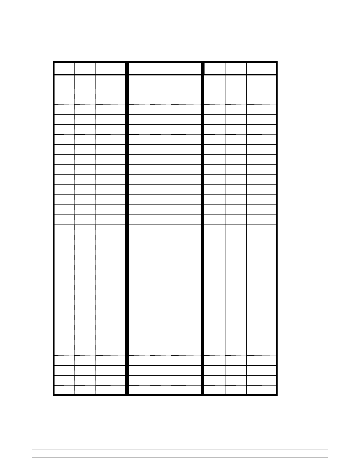
Thermistor Curve Chart
F. C. KOHM F. C. KOHM F. C. KOHM
-10 - 23.3 118.201 22 -5.5 43.530 54 12.2 17.915
-9 - 22.7 114.394 23 -5.0 42.340 55 12.7 17.451
-8 - 22.2 110.709 24 -4.4 41.136 56 13.3 16.998
-7 - 21.6 107.143 25 -3.8 39.967 57 13.8 16.557
-6 - 21.1 103.692 26 -3.3 38.830 58 14.4 16.128
-5 - 20.5 100.352 27 -2.7 37.727 59 15.0 15.710
-4 - 20.0 97.120 28 -2.2 36.654 60 15.5 15.315
-3 - 19.4 94.085 29 -1.6 35.612 61 16.1 14.929
-2 - 18.8 91.144 30 -1.1 34.599 62 16.6 14.554
-1 - 18.3 88.296 31 -0.5 33.616 63 17.2 14.187
0 - 17.7 85.536 32 0 32.660 64 17.7 13.830
1 - 17.2 82.863 33 0.5 31.760 65 18.3 13.482
2 - 16.6 80.273 34 1.1 30.885 66 18.8 13.143
3 - 16.1 77.765 35 1.6 30.035 67 19.4 12.812
4 - 15.5 75.334 36 2.2 29.207 68 20.0 12.490
5 - 15.0 72.980 37 2.7 28.403 69 20.5 12.185
6 - 14.4 70.627 38 3.3 27.620 70 21.1 11.888
7 - 13.8 68.350 39 3.8 26.859 71 21.6 11.598
8 - 13.3 66.147 40 4.4 26.120 72 22.2 11.315
9 - 12.7 64.014 41 5.0 25.400 73 22.7 11.039
10 - 12.2 61.951 42 5.5 24.721 74 23.3 10.769
11 -11.6 59.953 43 6.1 24.059 75 23.8 10.507
12 -11.1 58.021 44 6.6 23.416 76 24.4 10.250
13 - 10.5 56.150 45 7.2 22.789 77 25.0 10.000
14 - 10.0 54.340 46 7.7 22.180 78 25.5 9.763
15 -9.4 52.854 47 8.3 21.586 79 26.1 9.532
16 -8.8 51.409 48 8.8 21.009 80 26.6 9.306
17 -8.3 50.003 49 9.4 20.447 81 27.2 9.085
18 -7.7 48.636 50 10.0 19.900 82 27.7 8.870
19 -7.2 47.306 51 10.5 19.384 83 28.3 8.659
20 -6.6 46.012 52 11.1 18.881 84 28.8 8.454
21 -6.1 44.754 53 11.6 18.392 85 29.4 8.254
When checking a thermistor probe, first determine the temperature at the probe and find it on this chart, along with
the correct ohmmeter reading. If your ohmmeter reading varies from the correct reading, determine whether the
difference is acceptable. If a probe is faulty, the difference will be great.
Models 702 & 772 Thermistor Control
7
Page 12

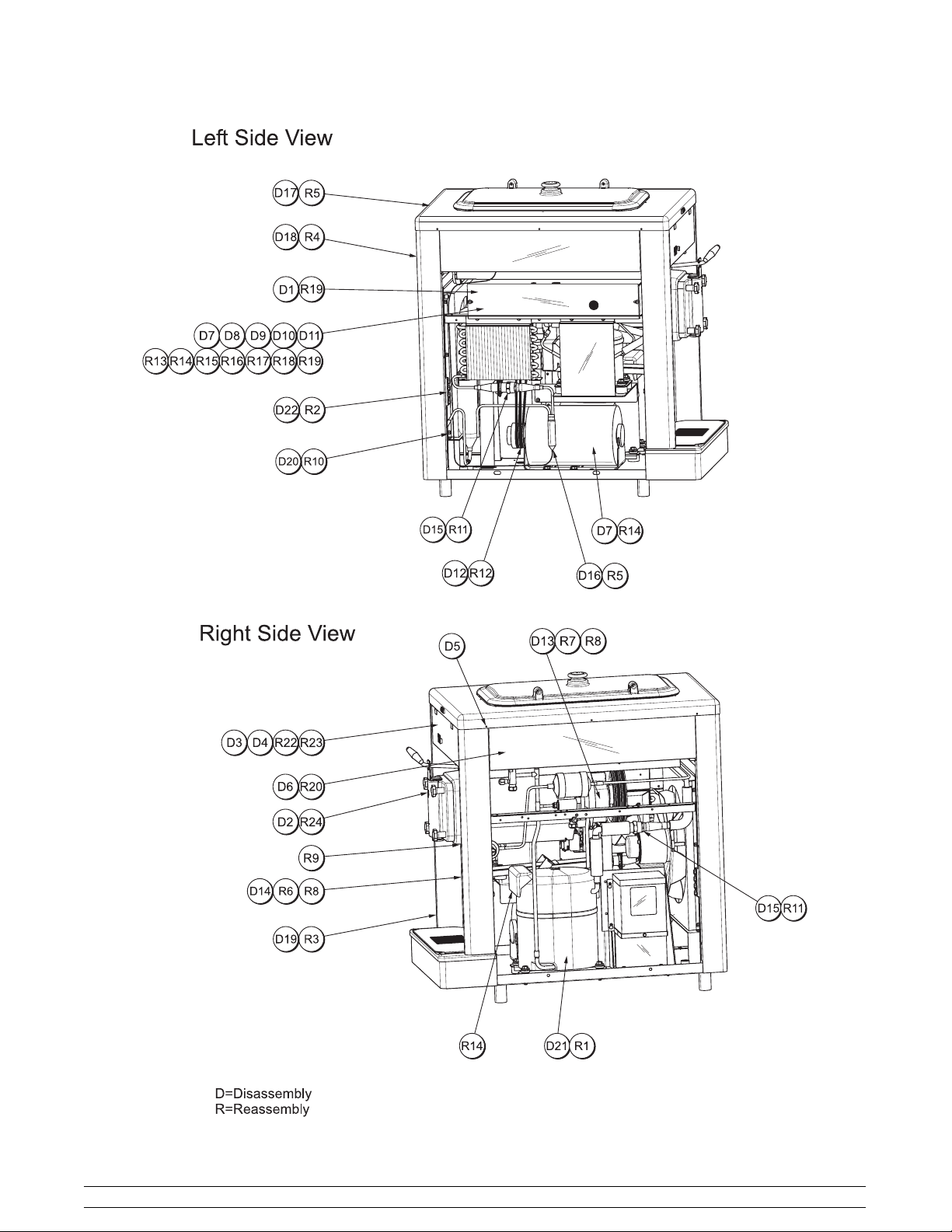
Section 3 Semi- Assembled Navy Units
To disassemble and assemble the Model 702 unit for
installation in a Navy submarine, perform the following
steps. Use the illustrations on page 12 for the
numerical references.
Disassembly
Step 1
Remove the rear panel, both lower side panels, and
the control box cover.
Step 2
Remove the door assembly, the drip pan, the beater
assembly, and the shaft from the front of the unit.
Step 3
Remove the decorative plate from the front of the unit,
then the fasteners from the following: (1) 24V
transformer , (2) draw switch, (3) thermistor board, and
(4) hopper temperature control.
Step 4
Disconnect the mix low light wires, and remove the
thermistor probe and mix hopper temperature probe
from their respective bulb well locations.
Step 5
Using a drill (1/8” to 5/32” bit), remove all (8) hood
rivets.
Step 6
Remove the upper side panels, (remove the rear
screws, then the lower front screws, then swing the
panel out and up to remove the upper front screws).
Step 7
Disconnect the beater motor wires from the right hand
side of the beater motor start relay. Remove the high
pressure cut out wire and blue wire from the beater
motor relay overload. Disconnect the high pressure
cutout wire to the #13 terminal on the compressor
relay and disconnect the blue wire from the
transformer (if applicable).
Step 8
Remove the main condenser fan motor wire and the
orange with white stripe wire from the compressor
relay #14 terminal and remove the splice caps from the
white wires in the control box (save the white jumper
wire). Remove the fan motor ground wire.
Step 9
Remove the splice cap from the Danfoss system white
with black stripe wire and white wire. Disconnect and
remove the control channel wires, the black and gray
wire from mix level sensor, the white with red stripe
wire from the compressor relay coil, and the orange
wire from the beater motor relay coil.
Step 10
For 115 volt units, disconnect the capacitor relay box
assembly wires from the compressor relay, (or on 460
volt units the transformer wires from the beater motor
relay), in the control box. Disconnect the compressor
wires at the compressor.
Step 11
Disconnect the purple mix low probe wire and remove
the control box from the unit.
Step 12
Remove the belts from the pulleys.
Step 13
Remove the two allen screws that secure the gearbox
to the rear shell support. Remove the two screws that
secure the drip tray guide, and the two screws that
secure the auxiliary compressor bracket to the rear
shell support.
Step 14
Remove the two carriage bolts and nuts that secure
the front of the shell to the front panel.
Step 15
Disconnect all 5 sets of refrigeration junction fittings (2
on auxiliary, and 3 on main system). Use two wrenches
and do not allow copper tubing to twist.
Remove discharge line coupling from the bracket on
right side.
Step 16
Fasten the Danfoss dryer/capillary tube assembly to
the shell assembly to protect the capillary tube from
damage.
Step 17
Remove the shell and hood assembly in one piece.
Step 18
Remove the rear corner trim from the frame.
Semi- Assembled Navy Units
8
Models 702 & 772
Page 13

Step 19
Remove the front panel from the frame.
Step 20
Remove the condenser mounting screws (from the top
of the bracket), remove the fan blade through the right
side, and then remove the condenser, shroud, and
receiver assembly.
Step 21
Remove the main compressor.
Step 22
Remove the fasteners that connect the top of the
frame to the bottom of the frame. Remove the top half
of the frame that includes the Danfoss compressor and
condenser.
Assembly
Step 10
Slide the condenser, shroud and receiver assembly
into place, then install the fan blade before bolting the
condenser in. (Note: The fan blade should be
positioned 1/3 within the shroud and 2/3 out.) Be sure
the fan blade turns freely.
Attach the cap tube to the clips on the side of the
condenser.
Step 11
Connect the compressor discharge coupling to the
bracket on the right side of the shell. Connect all of the
refrigerant couplings. Use two wrenches, and do not
allow the copper tubing to twist. Perform leak check
on both refrigeration systems.
Step 12
Install the belts on the pulleys.
Step 1
Mount the compressor to the base pan.
Step 2
Mount and fasten the upper frame with the auxiliary
system to the lower frame. Fasten the auxiliary
compressor support to the rear shell support.
Step 3
Install the front panel assembly and connect the drip
tray guide to the rear shell support.
Step 4
Install the rear corner trim.
Step 5
Install the shell and hood assembly. Connect the dryer
and cap tube assembly to the Danfoss condenser
assembly. (Be very careful with the cap tube.)
Step 6
Install the two carriage bolts through the front panel
assembly, and place the nuts on the bolts to secure the
shell.
Step 7
Connect the gearbox to the rear shell support with two
allen head screws.
Step 13
Install the control box assembly with two screws.
Step 14
Connect the beater motor wires to the right hand side
of the beater motor start relay. Connect the capacitor
relay box wires to the compressor relay (if applicable)
or the black wires from the transformer to L1 and L2 on
the beater motor relay. Reconnect the compressor
wires at the compressor.
Step 15
Connect one high pressure cut out wire to the #95
terminal on the beater motor overload, and connect
the blue wire from the control channel to the #96
terminal on the beater motor overload. Connect the
other high pressure cutout wire to the #13 terminal on
the compressor relay along with the blue wire from the
transformer (if applicable).
Step 16
Connect one fan wire and orange with white stripe wire
to the compressor relay #14 terminal, and splice the
other fan wire and all white wires, in the control box,
into two bundles using a white jumper wire. Connect
the fan motor ground wire to the back of the box.
Step 8
Tighten the nuts on the carriage bolts, then tighten the
screws that secure the gearbox.
Step 9
Using silicone, seal around the nose cone that
protrudes through the front panel assembly.
Models 702 & 772 Semi- Assembled Navy Units
Step 17
Splice theDanfoss system white with black stripe wire.
Connect the control channel wires: the black and gray
wire to the mix level sensor, the white with red stripe
wire to the compressor relay coil, and the orange wire
to the beater motor relay coil.
9
Page 14

Step 18
Connect the purple mix low probe wire.
Note: Double check all of the wire connections with
the wiring diagram.
Step 22
Connect the mix low light wires, and replace the
thermistor probe, and mix hopper temperature probe
into their respective bulb well locations.
Step 19
Connect the power cord, supplied by the end user, and
replace the control box cover.
Step 20
Replace the upper side panels and fasten the hood
with rivets supplied (p/n: 022517).
Step 21
Replace all the panels.
Note: Be sure the thermistor probe bulb well has
plenty of antifreeze before replacing the thermistor
probe.
Step 23
Fasten all the components in the control channel area
and install the decorative plate.
Step 24
Install the beater shaft, beater assembly and blade,
door assembly, and the drip pan in the front of the unit.
Semi- Assembled Navy Units
10
Models 702 & 772
Page 15
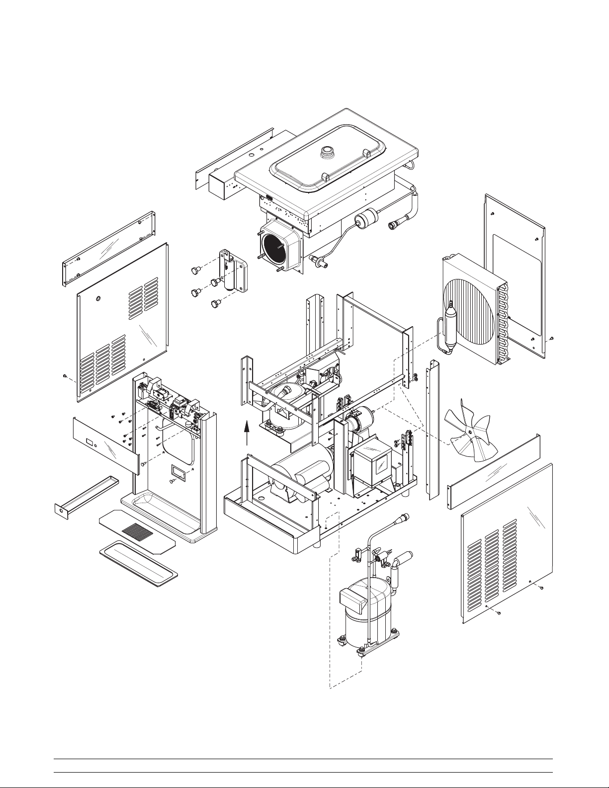
Semi- Assembled Model 702 Exploded View
Models 702 & 772 Semi- Assembled Navy Units
11
Page 16
Semi- Assembled Navy Units
12
Models 702 & 772
Page 17

Section 4 To the Operator
The freezer you have purchased has been carefully
engineered and manufactured to give you dependable
operation. The Taylor freezer, when properly operated
and cared for, will produce a consistent quality product.
Like all mechanical products, this machine will require
cleaning and maintenance. A minimum amount of care
and attention is necessary if the operating procedures
outlined in this manual are followed closely.
This Operator’s Manual should be read before
operating or performing any maintenance on your
equipment.
Your Taylor freezer will NOT eventually compensate
and correct for any errors during the set- up or filling
operations. Thus, the initial assembly and priming
procedures are of extreme importance. It is strongly
recommended that all personnel responsible for the
equipment’s operation review these procedures in
order to be properly trained and to make sure that there
is no confusion.
In the event that you should require technical
assistance, please contact your local authorized
Taylor Distributor.
Note: Your Taylor warranty is valid only if the parts are
authorized T aylor parts, purchased from the local
authorized Taylor Distributor, and only if all required
service work is provided by an authorized Taylor
service technician. Taylor reserves the right to deny
warranty claims on units or parts if non- Taylor
approved parts or incorrect refrigerant were installed
in the unit, system modifications were performed
beyond factory recommendations, or it is determined
that the failure was caused by abuse, misuse, neglect,
or failure to follow all operating instructions. For full
details of your Taylor Warranty, please see the Limited
Warranty section in this manual.
Note: Constant research results in steady
improvements; therefore, information in this
manual is subject to change without notice.
If the crossed out wheeled bin symbol is
affixed to this product, it signifies that this product is
compliant with the EU Directive as well as other similar
legislation in effect after August 13, 2005. Therefore,
it must be collected separately after its use is
completed, and cannot be disposed as unsorted
municipal waste.
The user is responsible for returning the product to the
appropriate collection facility, as specified by your local
code.
For additional information regarding applicable local
laws, please contact the municipal facility and/or local
distributor.
Compressor Warranty Disclaimer
The refrigeration compressor(s) on this unit are
warranted for the term stated in the Limited Warranty
section in this manual. However, due to the Montreal
Protocol and the U.S. Clean Air Act Amendments of
1990, many new refrigerants are being tested and
developed, thus seeking their way into the service
industry. Some of these new refrigerants are being
advertised as drop- in replacements for numerous
applications. It should be noted that in the event of
ordinary service to this unit’s refrigeration system,
only the refrigerant specified on the affixed data
label should be used. The unauthorized use of
alternate refrigerants will void your Taylor compressor
warranty. It is the unit owner’s responsibility to make
this fact known to any technician he employs.
It should also be noted that Taylor does not warrant the
refrigerant used in its equipment. For example, if the
refrigerant is lost during the course of ordinary service
to this machine, Taylor has no obligation to either
supply or provide its replacement either at billable or
unbillable terms. Taylor does have the obligation to
recommend a suitable replacement if the original
refrigerant is banned, obsoleted, or no longer available
during the five year warranty of the compressor.
The Taylor Company will continue to monitor the
industry and test new alternates as they are being
developed. Should a new alternate prove, through our
testing, that it would be accepted as a drop- in
replacement, then the above disclaimer would
become null and void. T o find out the current status of
an alternate refrigerant as it relates to your
compressor warranty, call the local Taylor Distributor
or the Taylor Factory. Be prepared to provide the
Model/Serial Number of the unit in question.
The freezer you have purchased uses
refrigerants 404a and 134a. These “ozone
friendly” refrigerants comply with the U.S. Clean
Air Act of 1990.
131206
Models 702 & 772 To the Operator
13
Page 18
Section 5 Safety
We, at Taylor Company, are concerned about the
safety of the operator at all times when they are
coming in contact with the unit and its parts. Taylor
makes every effort to design and manufacture built- in
safety features to protect both operators and service
technicians.
Installing and servicing refrigeration equipment can be
hazardous due to system pressure and electrical
components. Only trained and qualified service
personnel should install, repair, or service refrigeration
equipment. When working on refrigeration equipment,
observe precautions noted in the literature, tags and
labels attached to the unit, and other safety
precautions that may apply. Follow all safety code
requirements. Wear safety glasses and work gloves.
IMPORTANT - Failure to adhere to the
following safety precautions may result in severe
personal injury or death. Failure to comply with
these warnings may also damage the unit and/or
its components. Such damage may result in
component replacement and service repair
expenses.
DO NOT operate the unit without reading
this entire Operator Manual first. Failure to follow all of
these operating instructions may result in damage to
the unit, poor performance, health hazards, personal
injury, or death.
This unit is to be used only by trained
personnel. It is not intended for use by children or
people with reduced physical, sensory, or mental
capabilities, or lack of experience and knowledge.
Where limited equipment operation is allowed for
public use, such as a self- serve application,
supervision or instruction concerning the use of the
appliance by a person responsible for their safety is
required. Children should be supervised to ensure that
they do not play with the appliance.
S All repairs should be performed by an
authorized Taylor service technician.
S The main power supplies to the unit must be
disconnected prior to performing installation,
repairs, or maintenance.
S DO NOT operate the unit unless it is
properly grounded.
S DO NOT operate the unit with larger fuses
than specified on the unit’s data label.
S Units that are permanently connected to
fixed wiring and for which leakage currents
may exceed 10 mA, particularly when
disconnected or not used for long periods,
or during initial installation, shall have
protective devices such as a GFI, to protect
against the leakage of current, installed by
the authorized personnel to the local codes.
S Stationary units which are not equipped with
a power cord and a plug or another device
to disconnect the appliance from the power
source must have an all-pole disconnecting
device with a contact gap of at least 3 mm
installed in the external installation.
S Supply cords used with this unit shall be
oil-resistant, sheathed flexible cable not
lighter than ordinary polychloroprene or
other equivalent synthetic
elastomer-sheathed cord (Code designation
60245 IEC 57) installed with the proper cord
anchorage to relieve conductors from strain,
including twisting, at the terminals and
protect the insulation of the conductors from
abrasion.
If the supply cord is damaged, it must be
replaced by an authorized Taylor service
technician in order to avoid a hazard.
Failure to follow these instructions may result in
electrocution. Contact your local authorized Taylor
Distributor for service.
DO NOT use a water jet to clean or rinse the
unit. Failure to follow these instructions may result in
serious electrical shock.
Safety
14
Models 702 & 772
Page 19
S DO NOT allow untrained personnel to
operate this unit.
S DO NOT operate the unit unless all service
panels and access doors are restrained with
screws.
S DO NOT remove any internal operating
parts (including, but not limited to, freezer
door, beater, or scraper blades), unless all
control switches are in the OFF position.
Failure to follow these instructions may result in severe
personal injury, especially to fingers or hands, from
hazardous moving parts.
This unit has many sharp edges that can
cause severe injuries.
S DO NOT put objects or fingers in the door
spout. This may contaminate the product
and cause severe personal injury from blade
contact.
S USE EXTREME CAUTION when removing
the beater assembly. The scraper blades
are very sharp.
This unit must be placed on a level surface.
Extreme care should be taken when moving the unit for
any reason. Two or more persons are required to
safely move this unit. Failure to comply may result in
personal injury or damage to the unit.
Access to the service area of the unit must be
restricted to persons having knowledge and practical
experience with the unit, in particular as far as safety
and hygiene are concerned.
Cleaning and sanitizing schedules are
governed by your state or local regulatory agencies
and must be followed accordingly. Please refer to the
cleaning section of this Operator Manual for the proper
procedure to clean this unit.
This unit is designed to maintain product
temperature under 41°F(5°C). Any product being
added to this unit must be below 41°F(5°C). Failure to
follow this instruction may result in health hazards and
poor freezer performance.
DO NOT run the unit without product. Failure to follow
this instruction can result in damage to the unit.
DO NOT obstruct air intake and discharge openings:
Counter Model: 3” (76 mm) minimum air space on
both sides, 6” (152 mm) on the back, and 4- 1/4” (108
mm) on the bottom.
Console Model: 3” (76 mm) minimum air space on
sides and rear, and 7- 1/2” (191 mm) minimum on
bottom. Failure to follow this instruction may cause
poor freezer performance and damage to the
machine.
NOISE LEVEL: Airborne noise emission does not
exceed 78 dB(A) when measured at a distance of 1.0
meter from the surface of the machine and at a height
of 1.6 meters from the floor.
131206
Models 702 & 772 Safety
15
Page 20
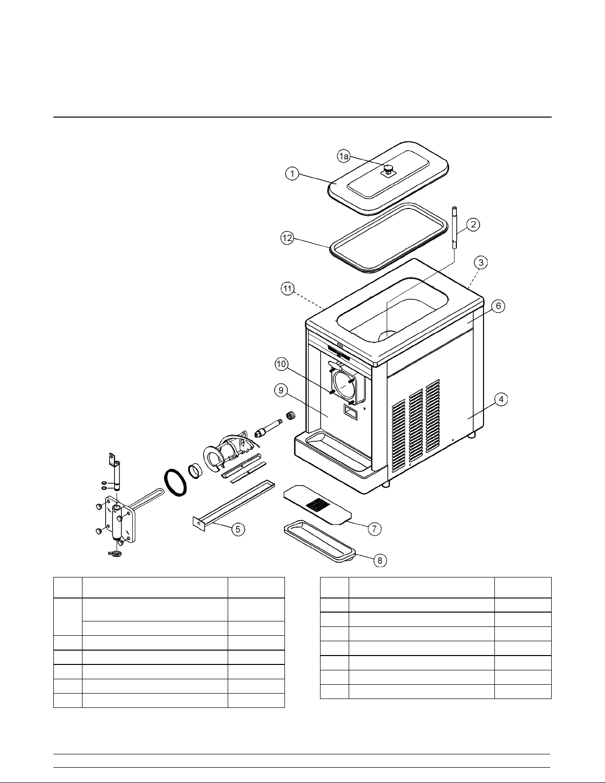
Section 6 Operator Parts Identification
Model 702
Item Description Part No.
*Cover A.- Hopper
(115V- 60- 1 only)
1
Cover A.- Hopper- Std. (460- 60 - 3) X38458
1a Knob - Hopper Cover 025429
2 Tube- Feed- SS- 5/32 Hole 028967- 2
3 Panel- Rear 702 Navy 050929
4 Panel- Side 702 Right 050928
5 Pan- Drip 13- 1/4 Long 039027
X39291
Operator Parts Identification
Item Description Part No.
6 Panel- Side 5472 HT Upper 042317
7 Shield- Splash 15” L x 5- 13/32 022763
8 Tray-Drip14-7/8Lx5-1/8SG 013690
9 Panel A. - Front X50930
10 Stud- Nose Cone 022822
11 Panel A.- Side Left X50940
12 Gasket- Hopper (460- 60- 3) 038375
*Insulated hopper cover that requires no gasket.
16
Models 702 & 772
Page 21
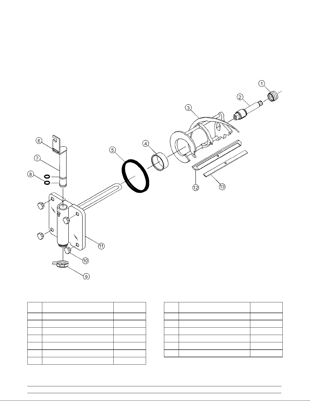
Model 702 Door Assembly
Item Description Part No.
1 Seal- Drive Shaft 032560
2 Shaft- Beater 033498
3 Beater A.- 4 Qt.- 1 Pin Support X49490
4 Bearing- Front 013116
5 Gasket- Door 5.177 ID x 5.9380 016672
6 Decal- Lift Plate Front 015200
7 Valv e A.- D raw X13624- SP
Models 702 & 772 Operator Parts Identification
Item Description Part No.
8 O- Ring - 1- 1/16 OD x .139 W 020571
9 Cap- Design- 1.188” ID 6 Point 013139- 6
10 Nut- Stud 021508
11 Door A.- 1 Spout- 4 Qt. X30269- SER
12 Blade- Scraper- Plastic 046237
13 Clip- Scraper Blade 8.75 Inch 046238
17
Page 22

Model 772
Item Description Part No.
1 Pan- Drip 11- 5/8 Long 027503
2 Cover A.- Hopper- Insulated X39291
2a Knob- Hopper Cover 025429
3 Tube- Feed- SS 028967- 3
4 Panel- Upper Side Left 029981
5 Stud- Nose Cone 022822
6 Tray- Drip 029998
7 Shield- Splash 029997
Operator Parts Identification
Item Description Part No.
8 Panel- Service 029976
9 Panel A.- Front X50835
10 Panel A.- Side Lower Right X44855
11 Panel- Side Top L- R 029978
12 Panel- Rear 029996
13 Panel- Upper Side Right 029980
14 Panel A.- Side Lower Left X44853
18
Models 702 & 772
Page 23

Model 772 Door Assembly
Item Description Part No.
1 Seal- Drive Shaft 032560
2 Shaft- Beater 033498
3 Beater A.- 7 Qt.- 1 Pin Support X46233
4 Bearing- Front 013116
5 Gasket- Door 5.177 ID x 5.9380 016672
6 Decal- Lift Plate Front 015200
7 Val ve A . - Dra w X13624- SP
Models 702 & 772 Operator Parts Identification
Item Description Part No.
8 O- Ring 1 - 1/16 OD x .139 W 020571
9 Cap- Design 1.188” ID 6 Point 013139- 6
10 Nut - Stud 021508
11 Door A.- 1 Spout 7 Qt. X30272- SER
12 Blade - Scraper- Plastic 046237
13 Clip- Scraper Blade - 8.75 Inch 046238
19
Page 24

Section 7 Important: To the Operator
Indicator Light “Mix Low”
The Models 702 and 772 are equipped with a “MIX
LOW” light located on the front of the machine. When
the light begins to flash, it indicates that the mix hopper
has a low supply of mix. At this time, the hopper should
be filled with mix. If you neglect to add mix when the
light begins to flash, eventual damage to the beater,
blades, drive shaft, and freezer door may occur.
Figure 2
Control Switch
The center position is “OFF”. The right position is
“AUTO”, which activates the beater motor and the
refrigeration system. The left position is “WASH”
which activates the beater motor only .
Figure 3
Reset Button
On a Model 702, the reset button is located under the
left upper side panel. On the Model 772, the reset
button is located on the lower front panel.
Symbol Definitions
The following chart identifies the symbol definitions
used on the operator switches.
= The “WASH” keypad.
= The “OFF” keypad.
= The “ON/AUTO” keypad.
The reset button protects the beater motor from an
overload condition. If an overload occurs, the reset
mechanism will trip. To properly reset the freezer,
place the control switch in the “OFF” position. Press
the reset button firmly. Place the control switch in the
“WASH” position and observe the freezer’s
performance. Once satisfied, place the control switch
back in the “AUTO” position.
Figure 4
Important: To the Operator
20
Models 702 & 772
Page 25

Optional Features
IMPORTANT: Do not use metal objects to
press the reset button.
Thermistor Control
The viscosity (thickness) of the product is controlled by
a temperature sensing device called the thermistor. To
achieve a thicker product, turn the control clockwise,
and turn the control counterclockwise to achieve a
thinner product. Allow the refrigeration system to cycle
on and off 2 or 3 times before an accurate consistency
can be evaluated.
Draw Rate
The draw rate can be adjusted by raising and lowering
the draw switch bracket. A technician should perform
this task, and set the rate at 5 to 7.5 ounces of product
per 10 seconds.
Separate Hopper Refrigeration System
(SHR)
“Standby”
The Separate Hopper Refrigeration System (SHR)
and the Cylinder Temperature Retention System
(CTR) are standard features. This feature is referred
to as “STANDBY”. The SHR incorporates the use of a
separate small refrigeration system to maintain the
mix temperature in the hopper to below 40_F. (4 . 4 _C.)
This assures bacteria control. The CTR works with the
SHR to maintain a good quality product. During long
“No Sale” periods, it becomes necessary to warm the
product in the freezing cylinder to approximately 35_F.
to 40_F. ( 1.7_C. to 4.4_C.) to prevent overbeating and
product breakdown.
Note:Some local health codes do not permit the
use of “STANDBY”.
ALWAYS FOLLOW LOCAL HEALTH CODES.
IMPORTANT: Make sure your hands are
sanitized before performing these instructions:
To activate SHR and CTR, place the air tube (end
without the hole) into the mix inlet hole.
Place the control switch in the “AUTO” position, and
turn the STANDBY switch to the “ON” position. The
unit will operate as a refrigerator for product in the
hopper and freezing cylinder.
To remove the unit from the “STANDBY” mode, place
the control switch in the “AUTO” position, and turn the
standby switch to the “OFF” position. The unit will
resume the normal operating mode.
When the unit cycles off, remove the hopper cover,
and place the feed tube in its original position.
Replace the hopper cover.
IMPORTANT: The “STANDBY” mode
should not be used in lieu of daily disassembly,
cleaning, and sanitizing. Follow your local health
codes regarding this issue.
Models 702 & 772 Important: To the Operator
21
Page 26

Section 8 Operating Procedures
The Model 702 has been selected to show you the
pictured step- by- step operating procedures for both
models contained in this manual. These two models,
for practical purposes of operation, are the same.
They both store 20 quarts (18.9 liters) of mix in the
hopper. The mix then flows by gravity through a mix
feed tube down into the freezing cylinder.
Locate your model number below to determine the
characteristics of your freezer:
702: (1) 4 quart (3.8 liter) freezing cylinder.
772: (2) 7 quart (6.6 liter) freezing cylinders.
We begin our instructions at the point where we enter
the store in the morning and find the parts
disassembled and laid out to air dry from the previous
night’s cleaning.
The following procedures will show you how to
assemble the parts into the freezer, sanitize them, and
prime the freezer with fresh mix in preparation to serve
your first portion.
Insert the drive shaft through the rear shell bearing in
the freezing cylinder and engage the hex end firmly
into the gear box coupling.
Figure 5
If you are disassembling the machine for the first time
or need information to get to this starting point in our
instructions, turn to page 27, “Disassembly” and start
there.
Assembly
MAKE SURE THE CONTROL SWITCH IS IN
THE “OFF” POSITION TO ELIMINATE THE
CHANCE OF MOVING PARTS.
Note: When lubricating parts, use an approved food
grade lubricant (example: Taylor Lube).
Step 1
Install the drive shaft. Lubricate the groove and shaft
portion that comes in contact with the bearing on the
beater drive shaft. Slide the seal over the shaft and
groove until it fits into place. DO NOT lubricate the hex
end of the drive shaft. Fill the inside portion of the seal
with 1/4” more lubricant and evenly lubricate the flat
side of the seal that comes in contact with the bearing.
Figure 6
Step 2
Install the beater assembly . First check the scraper
blade(s) for any nicks or signs of wear. If any nicks are
present, replace the blade(s).
Figure 7
Operating Procedures
22
Models 702 & 772
Page 27

Note: To prevent costly damage, the hole in the
scraper blade must fit securely over the pin.
If the blades are in good condition, place the rear
scraper blade over the rear holding pin on the beater,
knife edge to the outside. Holding the rear blade on the
beater, slide the assembly halfway into the freezing
cylinder. Install the front scraper blade over the front
holding pin. Slide the beater assembly the rest of the
way into the freezing cylinder.
Figure 8
Figure 10
Step 4
Install the freezer door. Place the freezer door gasket
into the groove on the back of the freezer door. Slide
the front bearing over the baffle rod so the flanged
edge is against the door. Do not lubricate the gasket
or bearing.
Make sure the beater assembly is in position over the
drive shaft. Turn the beater slightly to be certain that
the beater is properly seated. When in position, the
beater will not protrude beyond the front of the freezing
cylinder.
Step 3
Install the draw valve. Slide the two o- rings into the
grooves on the draw valve and lubricate them with
Taylor Lube.
Figure 9
Figure 11
Insert the baffle rod through the beater in the freezing
cylinder. With the door seated on the freezer studs,
install the handscrews. Tighten equally in a crisscross
pattern to insure that the door is snug.
Lubricate the inside of the freezer door spout, top and
bottom. Insert the draw valve into the freezer door from
the top. It will be necessary to rotate the draw valve to
the left when assembling the door to the freezer.
Models 702 & 772 Operating Procedures
23
Figure 12
Page 28

Rotate the draw valve bracket to the left. Center it into
position by raising the draw arm and placing it into the
slotted groove of the draw valve bracket.
Figure 13
Step 5
Snap the design cap over the end of the door spout.
Step 8
Slide the rear drip pan into the hole(s) in the side panel.
Sanitizing
Step 1
Prepare a pail of an approved 100 PPM sanitizing solution (examples: 2- 1/2 gal. [9.5 liters] of Kay- 5R or
2 gal. [7.6 liters] of Stera- SheenR). USE WARM WATER AND FOLLOW
Step 2
Pour the sanitizing solution into the hopper and allow
it to flow into the freezing cylinder.
Figure 14
Step 6
Lay the mix feed tube in the bottom of the mix hopper.
Repeat Steps 1 through 6 for the other side of the
freezer on the Model 772.
Step 7
Install the front drip tray and splash shield under the
door spout(s).
Figure 15
Figure 16
Step 3
While the solution is flowing into the freezing cylinder,
brush clean the hopper. While cleaning the mix hopper,
take particular care in brushing the mix level sensing
probe on the rear wall of the hopper, the mix inlet hole,
and the mix feed tube.
Figure 17
090303
Operating Procedures
24
Models 702 & 772
Page 29

Step 4
Place the control switch in the “WASH” position. This
will cause the sanitizing solution in the freezing
cylinder to agitate. Allow the solution to agitate for five
minutes.
Figure 18
Step 5
Place an empty pail beneath the door spout and raise
the draw arm. Draw off all the sanitizing solution.
Step 7
Stand the mix feed tube in the corner of the mix hopper.
Figure 20
Repeat Steps 1 through 7 for the other side of the
freezer on the Model 772.
Priming
Prime the machine as close to the time of first product
draw as possible.
Figure 19
Step 6
When the sanitizer stops flowing from the door spout,
lower the draw arm and place the control switch in the
“OFF” position.
Note: You have just sanitized the freezer;
therefore, be sure your hands are sanitized before
continuing these instructions.
Step 1
Place a mix pail beneath the door spout and raise the
draw arm. Pour two gallons (7.6 liters) of fresh mix into
the hopper and allow it to flow down into the freezing
cylinder. This will force out any remaining sanitizing
solution. When full strength mix is flowing from the
door spout, lower the draw arm.
Figure 21
Models 702 & 772 Operating Procedures
25
Page 30

Step 2
When the mix has stopped bubbling down into the
freezing cylinder, install the mix feed tube into the mix
inlet hole.
Figure 22
Step 3
Place the control switch in the “AUTO” position. When
the unit cycles off, the product will be at serving
temperature.
Step 5
Place the mix hopper cover in position.
Figure 24
Repeat Steps 1 through 5 for the other side of the
freezer on the Model 772.
Figure 23
Step 4
Fill the hopper with mix. As the mix level comes in
contact with the mix level sensing probe on the rear
wall of the hopper, the “MIX LOW” light will extinguish.
Closing Procedure
To disassemble your unit, the following items will be
needed:
S Two cleaning pails
S Sanitized stainless steel rerun can with lid
S Necessary brushes (provided with freezer)
S Cleaner
S Single service towels
Operating Procedures
26
Models 702 & 772
Page 31

Draining Product From the
Freezing Cylinder
Step 1
Place the control switch in the “OFF” position.
Repeat these steps for the second freezing cylinder
on the Model 772.
Cleaning
Step 2
Remove the hopper cover and the mix feed tube. Take
these parts to the sink for cleaning.
Step 3
If local health codes permit the use of rerun,place
a sanitized, NSF approved stainless steel rerun
container beneath the door spout. Place the control
switch in the “WASH” position and raise the draw arm.
When all the product stops flowing from the door
spout, lower the draw arm and place the control switch
in the “OFF” position. Place a sanitized lid on the rerun
container and place it in the walk- in cooler.
(Note: For additional information regarding the proper
use of rerun, see item 5 on page 29.)
Repeat these steps for the second freezing cylinder
on the Model 772.
Note: If local health codes DO NOT permit the use
of rerun, the productmust be discarded. Follow the
instructions in the previous step, except drain the
product into a mix pail and properly discard the mix.
ALWAYS FOLLOW LOCAL HEALTH CODES.
Step 1
Prepare a pail of an approved 100 PPM cleaning solution (examples: 2- 1/2 gal. [9.5 liters] of Kay- 5R or
2 gal. [7.6 liters] of Stera- SheenR). USE WARM WATER AND FOLLOW THE MANUFACTURER’S
SPECIFICATIONS.
Step 2
Pour the cleaning solution into the hopper and allow it
to flow into the freezing cylinder.
Step 3
While the solution is flowing into the freezing cylinder,
brush clean the mix hopper, the mix inlet hole, and the
mix level sensing probe.
Step 4
Place the control switch in the “WASH” position. This
will cause the cleaning solution in the freezing cylinder
to agitate.
Step 5
Place an empty mix pail beneath the door spout and
raise the draw arm. Draw off all the cleaning solution.
When the solution stops flowing from the door spout,
lower the draw arm and place the control switch in the
“OFF” position.
Repeat Steps 1 through 5 for the second freezing
cylinder on the Model 772.
Rinsing
Step 1
Pour two gallons (7.6 liters) of cool, clean water into
the mix hopper. With the brushes provided, scrub the
mix hopper, the mix inlet hole, and the mix level
sensing probe.
Step 2
With a mix pail beneath the door spout, place the
control switch in the “WASH” position and raise the
draw arm. Drain all the rinse water from the freezing
cylinder. When the rinse water stops flowing from the
door spout, lower the draw arm and place the control
switch in the “OFF” position.
Repeat this procedure until the rinse water being
drawn from the freezing cylinder is clear.
Models 702 & 772 Operating Procedures
Disassembly
Note: Failure to remove parts, brush clean and then
air dry these parts, will result in damage to the related
parts.
Step 1
BE SURE THE CONTROL SWITCH IS IN
THE “OFF” POSITION TO ELIMINATE THE
CHANCE OF MOVING PARTS.
Step 2
Remove the handscrews, the freezer door, the gasket,
the front bearing, the beater, the scraper blade(s), and
the drive shaft from the freezing cylinder. Take these
parts to the sink for cleaning.
090303
27
Page 32

Step 3
Remove the rear drip pan from the front panel.
Note: If the drip pan is filled with an excessive amount
of mix, it is an indication that the drive shaft seal should
be replaced or was improperly lubricated.
Repeat these steps for the second freezing cylinder
on the Model 772.
Step 4
Remove the front drip tray and the splash shield.
Brush Cleaning
Step 1
Prepare a sink with an approved cleaning solution
(examples: Kay- 5R or Stera- SheenR). USE WARM
WATER AND FOLLOW THE MANUFACTURER’S
SPECIFICATIONS
If an approved cleaner other than Kay- 5R or
Stera- SheenR is used, dilute it according to the label
instructions. IMPORTANT: Follow the label directions.
Too STRONG of a solution can cause parts damage.
Too MILD of a solution will not provide adequate
cleaning. Make sure all brushes provided with the
freezer are available for brush cleaning.
Step 2
Remove the seal(s) from the drive shaft(s).
Step 3
From the freezer door(s) remove:
S the gasket(s)
S the front bearing(s)
S the design cap(s)
S the draw valve(s)
Remove all o- rings.
Note: To remove o- rings, use a single service towel
to grasp the o- ring. Apply pressure in an upward
direction until the o- ring pops out of its groove. With
the other hand, push the top of the o- ring forward. It
will roll out of the groove and can be easily removed.
If there is more than one o- ring to be removed, always
remove the rear o- ring first. This will allow the o- ring
to slide over the forward rings without falling into the
open grooves.
Step 4
Thoroughly brush clean all disassembled parts in the
cleaning solution, making sure all lubricant and mix film
is removed. Take particular care to brush clean the
draw valve core in the freezer door(s). Place all the
cleaned parts on a clean dry surface to air dry
overnight.
Step 5
Return to the freezer with a small amount of cleaning
solution. With the black bristle brush, brush clean the
rear shell bearing(s) at the back of the freezing
cylinder(s).
Figure 25
Step 6
Wipe clean all exterior surfaces of the freezer.
Operating Procedures
28
Models 702 & 772
Page 33

Section 9 Important: Operator Checklist
During Cleaning and Sanitizing
ALWAYS FOLLOW LOCAL HEALTH CODES.
Cleaning and sanitizing schedules are governed
by federal, state, or local regulatory agencies,
and must be followed accordingly. If the unit
has a “Standby mode”, it must not be used in
lieu of proper cleaning and sanitizing
procedures and frequencies set forth by the
ruling health authority. The following check
points should be stressed during the cleaning
and sanitizing operations.
CLEANING AND SANITIZING MUST BE
PERFORMED DAILY.
T roubleshooting Bacterial Count
the rerun with fresh mix in a ratio of 50/50 during
the day’s operation.
j 6. On a designated day of the week, run the mix as
low as feasible and discard after closing. This
will break the rerun cycle and reduce the
possibility of high bacteria and coliform counts.
j 7. Properly prepare the cleaning and sanitizing
solutions. Read and follow label directions
carefully. Too strong of a solution may damage
the parts and too weak of a solution will not do
an adequate job of cleaning or sanitizing.
j 8. The temperature of the mix in the mix hopper
and walk- in cooler should be below 40_F.
(4.4_C.).
Regular Maintenance Checks
j 1. Thoroughly clean and sanitize the machine
regularly, including complete disassembly and
brush cleaning.
j 2. Use all brushes supplied for thorough cleaning.
The brushes are specially designed to reach all
mix passageways.
j 3. Use the white bristle brush to clean the mix inlet
hole which extends from the mix hopper down
to the rear of the freezing cylinder.
j 4. Use the black bristle brush to thoroughly clean
the rear shell bearing located at the rear of the
freezing cylinder. Be sure there is a generous
amount of cleaning solution on the brush.
j 5. IF LOCAL HEALTH CODES PERMIT THE
USE OF RERUN, make sure the mix rerun is
stored in a sanitized, covered stainless steel
container and is used the following day. DO
NOT prime the machine with rerun. When using
rerun, skim off the foam and discard, then mix
Models 702 & 772 Important: Operator Checklist
j 1. Rotate scraper blades to allow both sides of the
knife edge to wear evenly. This will contribute to
self- sharpening and help maintain fast, efficient
freezing.
j 2. Replace scraper blades that are nicked,
damaged or worn.
j 3. Before installing the beater, be certain that
scraper blades are properly attached over the
pins.
j 4. Check the rear shell bearing for signs of wear
(excessive mix leakage in rear drip pan) and be
certain it is properly cleaned.
j 5. Using a screwdriver and cloth towel, keep the
rear shell bearing and the female hex drive
socket clean and free of lubricant and mix
deposits.
090303
29
Page 34

j 6. Dispose of o- rings and seals if they are worn,
torn, or fit too loosely, and replace with new
ones.
j 7. Follow all lubricating procedures as outlined in
“Assembly”.
j 8. Check the condensers for accumulation of dirt
and lint. Dirty condensers will reduce the
efficiency and capacity of the machine.
Condensers should be cleaned monthly with a
soft brush. Never use screwdrivers or other
metal probes to clean between the fins.
Note: For machines equipped with an air filter,
it will be necessary to vacuum clean the filters
on a monthly schedule.
Winter Storage
If the place of business is to be closed during the winter
months, it is important to protect the freezer by
following certain precautions, particularly if the
building is subject to freezing conditions.
Disconnect the freezer from the main power source to
prevent possible electrical damage.
On water cooled freezers, disconnect the water
supply. Relieve pressure on the spring in the water
valve. Use air pressure on the outlet side to blow out
any water remaining in the condenser. This is
extremely important. Failure to follow this procedure
may cause severe and costly damage to the
refrigeration system.
Your local Taylor Distributor can perform this service
for you.
j 9. On water cooled units, check the water lines for
kinks or leaks. Kinks can occur when the
machine is moved back and forth for cleaning or
maintenance purposes. Deteriorated or
cracked water lines should be replaced only by
an authorized Taylor technician.
Wrap detachable parts of the freezer such as the
beater, blades, drive shaft, and freezer door . Place
these parts in a protected, dry place. Rubber trim parts
and gaskets can be protected by wrapping them with
moisture- proof paper. All parts should be thoroughly
cleaned of dried mix or lubrication which attract mice
and other vermin.
060109
Important: Operator Checklist
30
Models 702 & 772
Page 35

Section 10 Troubleshooting Guide
PROBLEM PROBABLE CAUSE REMEDY PAG E
REF.
1. No product being
dispensed with the draw
valve open and the control
switch in AUTO.
2. The product is too cold. a. The temperature control is
a. The freezer door is
installed upside down.
b. There is a freeze- up in
the mix inlet hole.
c. The beater motor is out on
reset.
d. The beater is rotating
counterclockwise.
e. The draw valve is
connected to the draw
arm incorrectly.
f. The circuit breaker is off
or the fuse is blown.
g. There is inadequate mix in
the hopper.
set too cold.
a. Install the door correctly. 23
b. Call service technician to
adjust the hopper
temperature.
c. Reset the freezer. 20
d. Contact service technician
to correct the rotation to
clockwise.
e. The draw valve bracket
must be correctly attached
to the draw arm.
f. Turn the breaker on or
replace the fuse.
g. Fill the hopper with mix. 25
a. Adjust the temperature
control knob warmer.
--
--
24
--
21
b. The draw handle is not
fully closed.
3. The product appears too
soft.
Models 702 & 772 Troubleshooting Guide
a. The temperature control is
set too warm.
b. There is not enough air
space around the unit.
(A/C)
c. The scraper blade(s) are
worn.
d. Dirty condenser. d. Clean regularly. 30
e. The mix is out of date. e. Use only fresh mix. --
f. The beater is rotating
counterclockwise.
g. Loss of water (W/C) g. Locate cause of water
31
b. The draw handle must be
fully closed.
a. Adjust the temperature
control knob colder.
b. Allow for adequate air flow
across the condenser.
c. Replace scraper blades
regularly.
f. Contact service technician
to correct rotation to
clockwise.
loss and correct.
--
21
1
35
--
30
Page 36

PROBLEM PROBABLE CAUSE REMEDY PAG E
REF.
3. The product appears too
soft. (Cont’d.)
4. The mix in the hopper is
too cold.
5. The mix in the hopper is
too warm.
6. The drive shaft is stuck in
the gear box coupling.
h. Product is broken down
from overbeating.
a. The temperature is out of
adjustment.
a. The temperature is out of
adjustment.
b. Hopper cover is not in
position.
c. The control switch is OFF. c. Place the control switch in
d. Warm mix was placed in
the hopper.
a. Rounded corners of drive
shaft, coupling, or both.
h. Draw off some product to
allow fresh product to
enter the freezing cylinder.
a. Call service technician to
adjust the hopper
temperature.
a. Call service technician to
adjust the hopper
temperature.
b. Place the cover in
position.
AUTO.
d. Mix added to the hopper
must be below 40_F
(4.4_C).
a. Call service technician to
correct the cause and
replace the necessary
components. Do not
lubricate the end of the
drive shaft.
--
--
--
26
26
--
--
7. The freezing cylinder walls
are scored.
8. Excessive mix leakage
into the rear drip pan.
a. The scraper blade(s) are
not installed over the
beater pins. The pins on
the beater are broken.
b. The beater assembly is
bent.
c. Missing or worn front
bearing.
a. Worn or missing drive
shaft seal.
b. Inadequate lubrication of
drive shaft seal.
c. Worn rear shell bearing. c. Call service technician to
a. Blade(s) must fit over the
pins on the beater. Call
service technician to
repair the beater
assembly.
b. Call service technician to
repair or replace beater
and to correct cause of
insufficient mix in freezing
cylinder.
c. Install or replace the front
bearing.
a. Replace regularly. 35
b. Lubricate properly. 22
replace rear shell bearing.
23
--
23
--
Troubleshooting Guide
32
Models 702 & 772
Page 37

PROBLEM PROBABLE CAUSE REMEDY PAG E
REF.
8. Excessive mix leakage
into the rear drip pan.
(Cont’d.)
9. Excessive mix leakage
from the door spout.
10. No freezer operation with
the control switch in
AUTO.
d. The drive shaft works
forward.
e. The seal is installed
inside- out on the drive
shaft.
f. The wrong type of
lubricant is being used
(example: petroleum base
lubricant.).
a. Worn or missing draw
valve o- rings.
b. Inadequate lubrication of
the draw valve o- rings.
c. The wrong type of
lubricant is being used
(example: petroleum base
lubricant.).
a. The unit is unplugged. a. Plug into wall receptacle. --
d. Call service technician to
correct.
e. Install correctly. 22
f. Use the proper lubricant
(example: Taylor Lube).
a. Replace regularly. 35
b. Lubricate properly. 23
c. Use the proper lubricant
(example: Taylor Lube).
--
--
--
b. Circuit breaker off or
blown fuse.
c. Beater motor out on reset. c. Reset the freezer. 20
1 1. Low overrun. a. Worn scraper blade(s). a. Replace regularly. 35
b. The mix feed assembly is
not installed.
c. Product is broken down
from over- beating.
12. The freezer door works
loose.
a. The freezer studs are
damaged.
b. The handscrews are
damaged.
c. There are enlarged holes
in the freezer door.
d. The handscrews are not
tightened.
e. The beater assembly is
rubbing the back of the
door.
b. Turn circuit breaker on or
replace fuse.
b. Install in mix inlet hole. 26
c. Draw off some product to
allow fresh product to
enter the freezing cylinder.
a. Call service technician to
replace studs.
b. Replace the handscrews. --
c. Replace the door. --
d. Tighten the handscrews
equally in a crisscross
pattern.
e. Call service technician to
correct the problem.
--
--
--
23
--
Models 702 & 772 Troubleshooting Guide
33
Page 38

T roubleshooting Thermistor
Components
Step 1
Power Switch in the “AUTO” Position
Using a voltmeter, check the two terminals connecting
the transformer wires to the controller. There should be
a reading of 24 volts (¦15%); if not, the transformer is
not receiving line voltage or the transformer is faulty
and should be replaced. If a proper reading is obtained,
proceed to the next step.
Step 2
Power Switch in the “AUTO” Position
Using a voltmeter, make certain L1 power is being
supplied to the common terminal of the controller. A
reading of line voltage should be obtained. To
accomplish this, measure voltage between the
common terminal and any L2 power source. If a proper
reading is not obtained, make sure there is line voltage
at the incoming power supply. If there is incoming
power, back track from the common terminal (L1) and
determine where L1 is being interrupted and correct
accordingly. If a proper reading is obtained, proceed to
the next step.
Step 4
Power Switch in the “OFF” Position
Check the probe resistance. Disconnect both the
yellow and black wires at the control, and measure
their resistance with an ohmmeter. At room
temperature, a reading of approximately 10,000 ohms
should be obtained. If these readings are not obtained,
replace the probe. When replacing the probe, fill the
bulb- well with antifreeze. Connect the yellow wire to
the white terminal and the black wire to the black
terminal.
Step 5
Power Switch in the “OFF” Position
Check the anticipator microswitch by removing the
wires connecting the switch to the controller, and
check for continuity. If switch continuity exists when
the draw handle is raised, the switch is effective.
Continuity should break when the draw handle is
lowered.
Step 3
Power Switch in the “AUTO” Position
Remove the probe wires from the controller. Place a
wire between the two probe terminals of the controller
to short the component. This should activate the
compressor. If this procedure does not activate the
compressor, check for line voltage. If there is line
voltage at the compressor contactor coil, the controller
is acceptable.
Troubleshooting Guide
34
Models 702 & 772
Page 39

Section 11 Parts Replacement Schedule
PART DESCRIPTION EVERY 3
MONTHS
Scraper Blade X
Drive Shaft Seal X
Drive Shaft O- Ring X
Freezer Door Gasket X
Front Bearing X
Draw Valve O- Ring X
White Bristle Brush, 3” x 7” Inspect & Replace
White Bristle Brush, 9/16” x 38” Inspect & Replace
White Bristle Brush, 1- 1/2” x 2” Inspect & Replace
Black Bristle Brush, 1” x 2” Inspect & Replace
Double- Ended Brush Inspect & Replace
EVERY 4
MONTHS
EVERY 6
MONTHS
if Necessary
if Necessary
if Necessary
if Necessary
if Necessary
ANNUALLY
Minimum
Minimum
Minimum
Minimum
Minimum
Models 702 & 772 Parts Replacement Schedule
35
Page 40

Section 12 Service Parts Functions
PART DESCRIPTION FUNCTION
Compressor Provides circulation of refrigerant.
Condenser (air or water cooled) Condenses refrigerant from a vapor to a liquid by removing
heat from the refrigerant.
Dryer Filter Removes foreign matter and moisture from the refrigerant.
Expansion Valve Meters liquid refrigerant from the liquid line into the insulated
shell evaporator .
Shell and Hopper Assembly Insulated evaporator providing freezing and storage of
product.
E.P.R. Valve Controls pressure in the hopper evaporator.
Beater Line Starter When the coil is energized, the relay closes. This permits
power to flow to the overload relay, then to the beater motor.
Compressor Relay When the coil is energized, the relay closes. This permits
power to flow to the compressor.
Control Switch When in “WASH”, the control switch permits power to travel to
the beater line starter. When in “AUTO”, it permits power to
travel to the thermistor control.
Thermistor Control Monitors product in the freezing cylinder. When the product
begins to get warm, the thermistor control allows power to
flow to the compressor relay.
Transformer Powers the thermistor control.
Mix Level Control Activates the “MIX LOW” light when the mix level in the
hopper becomes inadequate.
Door Switch When the draw arm is raised, a micro switch closes and
sends a signal to the thermistor control.
Water Valve (water cooled) Controls the flow of water to the condenser by sensing the
increasing and decreasing pressures at the high side of the
compressor.
High Pressure Switch Senses high head pressure at the compressor. In the event of
a high pressure situation, the switch breaks power to the
control switch and the freezer shuts down.
Blower (water cooled) Dissipates heat from the interior of the freezer.
Fan Motor (air cooled) Circulates air across the condenser.
Beater Motor Drives the gear unit which in turn rotates the beater assembly.
Filter Removes impurities from the refrigerant prior to the dryer.
Transformer Used on high voltage units to reduce incoming voltage down
to 230 volts to power the control circuitry.
Service Parts Functions
36
Models 702 & 772
Page 41

Section 13 Limited Warranty on Equipment
TAYLOR COMPANY LIMITED WARRANTY ON FREEZERS
Taylor Company, a division of Carrier Commercial Refrigeration, Inc. (“Taylor”) is pleased to provide this limited
warranty on new Taylor-branded freezer equipment available from Taylor to the market generally (the “Product”)
to the original purchaser only.
LIMITED WARRANTY
Taylor warrants the Product against failure due to defect in materials or workmanship under normal use and
service as follows. All warranty periods begin on the date of original Product installation. If a part fails due to
defect during the applicable warranty period, Taylor, through an authorized Taylor distributor or service agency,
will provide a new or re- manufactured part, at Taylor’s option, to replace the failed defective part at no charge for
the part. Except as otherwise stated herein, these are T aylor’s exclusive obligations under this limited warranty for
a Product failure. This limited warranty is subject to all provisions, conditions, limitations and exclusions listed
below and on the reverse (if any) of this document.
Product
Soft Serve
Frozen Yogurt
Shakes
Smoothies
Frozen Beverage
Batch Desserts
1. If the date of original installation of the Product cannot be verified, then the limited warranty period begins
ninety (90) days from the date of Product manufacture (as indicated by the Product serial number). Proof of
purchase may be required at time of service.
2. This limited warranty is valid only if the Product is installed and all required service work on the Product is
performed by an authorized Taylor distributor or service agency, and only if genuine, new Taylor parts are
used.
3. Installation, use, care, and maintenance must be normal and in accordance with all instructions contained in
the Taylor Operator’s Manual.
Insulated shell assembly Five (5) years
Refrigeration compressor
(except service valve)
Beater motors Two (2) years
Beater drive gear Two (2) years
Printed circuit boards and
Softech controls beginning
with serial number H8024200
Parts not otherwise listed in
this table or excluded below
LIMITED WARRANTY CONDITIONS
Part Limited Warranty Period
Five (5) years
Two (2) years
One (1) year
4. Defective parts must be returned to the authorized Taylor distributor or service agency for credit.
5. The use of any refrigerant other than that specified on the Product’s data label will void this limited warranty.
LIMITED WARRANTY EXCEPTIONS
This limited warranty does not
1. Labor or other costs incurred for diagnosing, repairing, removing, installing, shipping, servicing or handling of
defective parts, replacement parts, or new Products.
2. Normal maintenance, cleaning and lubrication as outlined in the Taylor Operator’s Manual, including cleaning
of condensers.
Models 702 & 772 Limited Warranty on Equipment
cover:
131206
37
Page 42

3. Replacement of wear items designated as Class “000” parts in the Taylor Operator’s Manual.
4. External hoses, electrical power supplies, and machine grounding.
5. Parts not supplied or designated by Taylor, or damages resulting from their use.
6. Return trips or waiting time required because a service technician is prevented from beginning warranty
service work promptly upon arrival.
7. Failure, damage or repairs due to faulty installation, misapplication, abuse, no or improper servicing,
unauthorized alteration or improper operation or use as indicated in the Taylor Operator’s Manual, including
but not limited to the failure to use proper assembly and cleaning techniques, tools, or approved cleaning
supplies.
8. Failure, damage or repairs due to theft, vandalism, wind, rain, flood, high water, water, lightning, earthquake
or any other natural disaster, fire, corrosive environments, insect or rodent infestation, or other casualty,
accident or condition beyond the reasonable control of Taylor; operation above or below the electrical or
water supply specification of the Product; or components repaired or altered in any way so as, in the
judgment of the Manufacturer, to adversely affect performance, or normal wear or deterioration.
9. Any Product purchased over the Internet.
10. Failure to start due to voltage conditions, blown fuses, open circuit breakers, or damages due to the
inadequacy or interruption of electrical service.
1 1. Electricity or fuel costs, or increases in electricity or fuel costs from any reason whatsoever.
12. Damages resulting from the use of any refrigerant other than that specified on the Product’s data label will
void this limited warranty.
13. Any cost to replace, refill or dispose of refrigerant, including the cost of refrigerant.
14. ANY SPECIAL, INDIRECT OR CONSEQUENTIAL PROPERTY OR COMMERCIAL DAMAGE OF ANY
NATURE WHATSOEVER. Some jurisdictions do not allow the exclusion of incidental or consequential
damages, so this limitation may not apply to you.
This limited warranty gives you specific legal rights, and you may also have other rights which vary from
jurisdiction to jurisdiction.
LIMITA TION OF WARRANTY
THIS LIMITED WARRANTY IS EXCLUSIVE AND IS IN LIEU OF ALL OTHER WARRANTIES, CONDITIONS
AND/OR REMEDIES UNDER THE LAW, INCLUDING ANY IMPLIED WARRANTIES OR CONDITIONS OF
MERCHANTABILITY OR FITNESS FOR A PARTICULAR PURPOSE. THE ORIGINAL OWNER’S SOLE
REMEDY WITH RESPECT TO ANY PRODUCTS SHALL BE REPAIR OR REPLACEMENT OF DEFECTIVE
COMPONENTS UNDER THE TERMS OF THIS LIMITED WARRANTY. ALL RIGHTS TO CONSEQUENTIAL
OR INCIDENT AL DAMAGES (INCLUDING CLAIMS FOR LOST SALES, LOST PROFITS, PRODUCT LOSS,
PROPERTY DAMAGES OR SERVICE EXPENSES) ARE EXPRESSLY EXCLUDED. THE EXPRESS
WARRANTIES MADE IN THIS LIMITED WARRANTY MAY NOT BE ALTERED, ENLARGED, OR CHANGED
BY ANY DISTRIBUTOR, DEALER, OR OTHER PERSON, WHATSOEVER.
LEGAL REMEDIES
The owner must notify Taylor in writing, by certified or registered letter to the following address, of any defect or
complaint with the Product, stating the defect or complaint and a specific request for repair, replacement, or other
correction of the Product under warranty, mailed at least thirty (30) days before pursuing any legal rights or
remedies.
Taylor Company
a division of Carrier Commercial Refrigeration, Inc.
750 N. Blackhawk Blvd.
Rockton, IL 61072
Limited Warranty on Equipment
38
Models 702 & 772
Page 43

Section 14 Limited Warranty on Parts
TAYLOR COMPANY LIMITED WARRANTY ON TAYLOR GENUINE P ARTS
Taylor Company, a division of Carrier Commercial Refrigeration, Inc. (“Taylor”) is pleased to provide this limited
warranty on new Taylor genuine replacement components and parts available from Taylor to the market generally
(the “Parts”) to the original purchaser only.
LIMITED WARRANTY
Taylor warrants the Parts against failure due to defect in materials or workmanship under normal use and service
as follows. All warranty periods begin on the date of original installation of the Part in the Taylor unit. If a Part fails
due to defect during the applicable warranty period, Taylor, through an authorized Taylor distributor or service
agency, will provide a new or re- manufactured Part, at T aylor’s option, to replace the failed defective Part at no
charge for the Part. Except as otherwise stated herein, these are Taylor’s exclusive obligations under this limited
warranty for a Part failure. This limited warranty is subject to all provisions, conditions, limitations and exclusions
listed below and on the reverse (if any) of this document.
Part’s Warranty Class Code or Part
Class 103 Parts¹ Three (3) months
Class 212 Parts² Twelve (12) months
Class 512 Parts Twelve (12) months
Class 000 Parts No warranty
Taylor Part #072454 (Motor- 24VDC *C832/C842*) Four (4) years
LIMITED WARRANTY CONDITIONS
1. If the date of original installation of the Part cannot be otherwise verified, proof of purchase may be required
at time of service.
2. This limited warranty is valid only if the Part is installed and all required service work in connection with the
Part is performed by an authorized Taylor distributor or service agency.
3. The limited warranty applies only to Parts remaining in use by their original owner at their original installation
location in the unit of original installation.
4. Installation, use, care, and maintenance must be normal and in accordance with all instructions contained in
the Taylor Operator’s Manual.
5. Defective Parts must be returned to the authorized Taylor distributor or service agency for credit.
6. This warranty is not intended to shorten the length of any warranty coverage provided pursuant to a separate
Taylor Limited Warranty on freezer or grill equipment.
Limited Warranty Period
7. The use of any refrigerant other than that specified for the unit in which the Part is installed will void this
limited warranty.
1, 2
Except that Taylor Part #032129SER2 (Compressor-Air-230V SERV) and Taylor Part #075506SER1
(Compressor-Air-115V 60HZ) shall have a limited warranty period of twelve (12) months when used in Taylor
freezer equipment and a limited warranty period of two (2) years when used in Taylor grill equipment.
131206
Models 702 & 772 Limited Warranty on Parts
39
Page 44

LIMITED WARRANTY EXCEPTIONS
This limited warranty does not
1. Labor or other costs incurred for diagnosing, repairing, removing, installing, shipping, servicing or handling of
defective Parts, replacement Parts, or new Parts.
2. Normal maintenance, cleaning and lubrication as outlined in the Taylor Operator’s Manual, including cleaning
of condensers or carbon and grease buildup.
3. Required service, whether cleaning or general repairs, to return the cooking surface assemblies, including
the upper platen and lower plate, to an operational condition to achieve proper cooking or allow proper
assembly of release sheets and clips as a result of grease build-up on the cooking surfaces, including but
not limited to the platen and plate, sides of the shroud or top of the shroud.
4. Replacement of cooking surfaces, including the upper platen and lower plate, due to pitting or corrosion (or
in the case of the upper platen, due to loss of plating) as a result of damage due to the impact of spatulas or
other small wares used during the cooking process or as a result of the use of cleaners, cleaning materials
or cleaning processes not approved for use by Taylor.
5. Replacement of wear items designated as Class “000” Parts in the Taylor Operator’s Manual, as well as any
release sheets and clips for the Product’s upper platen assembly.
6. External hoses, electrical power supplies, and machine grounding.
7. Parts not supplied or designated by Taylor, or damages resulting from their use.
8. Return trips or waiting time required because a service technician is prevented from beginning warranty
service work promptly upon arrival.
cover:
9. Failure, damage or repairs due to faulty installation, misapplication, abuse, no or improper servicing,
unauthorized alteration or improper operation or use as indicated in the Taylor Operator’s Manual, including
but not limited to the failure to use proper assembly and cleaning techniques, tools, or approved cleaning
supplies.
10. Failure, damage or repairs due to theft, vandalism, wind, rain, flood, high water, water, lightning, earthquake
or any other natural disaster, fire, corrosive environments, insect or rodent infestation, or other casualty,
accident or condition beyond the reasonable control of Taylor; operation above or below the gas, electrical or
water supply specification of the unit in which a part is installed; or Parts or the units in which they are
installed repaired or altered in any way so as, in the judgment of Taylor, to adversely affect performance, or
normal wear or deterioration.
1 1. Any Part purchased over the Internet.
12. Failure to start due to voltage conditions, blown fuses, open circuit breakers, or damages due to the
inadequacy or interruption of electrical service.
13. Electricity, gas or other fuel costs, or increases in electricity or fuel costs from any reason whatsoever.
14. Damages resulting from the use of any refrigerant other than that specified for the unit in which the Part is
installed will void this limited warranty.
15. Any cost to replace, refill or dispose of refrigerant, including the cost of refrigerant.
16. ANY SPECIAL, INDIRECT OR CONSEQUENTIAL PROPERTY OR COMMERCIAL DAMAGE OF ANY
NATURE WHATSOEVER. Some jurisdictions do not allow the exclusion of incidental or consequential
damages, so this limitation may not apply to you.
This limited warranty gives you specific legal rights, and you may also have other rights which vary from
jurisdiction to jurisdiction.
Limited Warranty on Parts
40
Models 702 & 772
Page 45

LIMITA TION OF WARRANTY
THIS LIMITED WARRANTY IS EXCLUSIVE AND IS IN LIEU OF ALL OTHER WARRANTIES, CONDITIONS
AND/OR REMEDIES UNDER THE LAW, INCLUDING ANY IMPLIED WARRANTIES OR CONDITIONS OF
MERCHANTABILITY OR FITNESS FOR A PARTICULAR PURPOSE. THE ORIGINAL OWNER’S SOLE
REMEDY WITH RESPECT TO ANY PRODUCTS SHALL BE REPAIR OR REPLACEMENT OF DEFECTIVE
PARTS UNDER THE TERMS OF THIS LIMITED WARRANTY. ALL RIGHTS TO CONSEQUENTIAL OR
INCIDENTAL DAMAGES (INCLUDING CLAIMS FOR LOST SALES, LOST PROFITS, PRODUCT LOSS,
PROPERTY DAMAGES OR SERVICE EXPENSES) ARE EXPRESSLY EXCLUDED. THE EXPRESS
WARRANTIES MADE IN THIS LIMITED WARRANTY MAY NOT BE ALTERED, ENLARGED, OR CHANGED
BY ANY DISTRIBUTOR, DEALER, OR OTHER PERSON, WHATSOEVER.
LEGAL REMEDIES
The owner must notify Taylor in writing, by certified or registered letter to the following address, of any defect or
complaint with the Part, stating the defect or complaint and a specific request for repair, replacement, or other
correction of the Part under warranty, mailed at least thirty (30) days before pursuing any legal rights or remedies.
Taylor Company
a division of Carrier Commercial Refrigeration, Inc.
750 N. Blackhawk Blvd.
Rockton, IL 61072
Models 702 & 772 Limited Warranty on Parts
41
Page 46

Section 15 Parts List
UPDATE
REMARKS PARTS
WARR.
CLASS
772
QTY.
702
DESCRIPTION PART
QTY.
NUMBER
+GUIDE- DRIP SEAL 028992 1 2 000
+NUT- BRASS BEARING 028991 1 2 000
+WASHER- BEARING LOCK 012864 1 2 000
+BLADE- SCRAPER- PLASTIC 9- 13/16L 046237 1 000
+CLIP- SCRAPER BLADE*8.75 INCH* 046238 1 103
+BLADE- SCRAPER- PLASTIC 9- 13/16L 046237 4 000
BEARING- FRONT 013116 1 2 000
BEARING- REAR SHELL *NICK.PLATE 031324 1 2 000
BEATER A.- 4QT- 1 PIN- SUPPORT X49490 1 103
BEATER A.- 7QT- 1 PIN- SUPPORT X46233 2 103
+CLIP- SCRAPER BLADE*8.75 INCH* 046238 4 103
BELT- AX45 045311 2 000
BELT- AX38 023873 4 000
BLOCK- TERMINAL 2P 039421 1 103 115V,60Hz,1PH
BLOCK- TERMINAL 3P 039423 1 2 103 460 V, 60Hz, 3 PH
BRUSH- DOUBLE ENDED- PUMP&FEED T 013072 1 1 000
BRUSH- DRAW VALVE 1- 1/2”OD X 3” 014753 1 1 000
BRUSH- MIX PUMP BODY- 3”X7”WHITE 023316 1 1 000
BRUSH- REAR BRG 1IN.DX2IN.LGX14 013071 1 1 000
CAP- DESIGN- 1.188”ID- 6 POINT 013139- 6 1 2 000
NO COMPONENTS REQUIRED FOR 3 PHASE
NO COMPONENTS REQUIRED FOR 3 PHASE
+CAPACITOR- RUN- 20UF/370V 023606 1 103 115V,60Hz,1PH
+CAPACITOR- START- 189- 227UF/33 033044 1 103 115V,60Hz,1PH
+RELAY- START- COMPRESSOR 049656 1 103 115V,60Hz,1PH
+CAPACITOR- START- 60UF- 220/275V 047703 1 1 103 230 V, 60 Hz, 1 PH
+COVER- TERMINAL- COMPRESSOR 047739 1 1 103 230 V, 60 Hz, 1 PH
COMPRESSOR L61B562DBEB 048727- 58 1 512 460 V, 60 Hz, 3 PH
COMPRESSOR L63A113DBEA 048259- 58 2 512 460 V , 60 Hz, 3 PH
COMPRESSOR L61B562BBAB 048727- 12 1 512 115V,60Hz,1PH
COMPRESSOR TL3G- R134A 047701- 1 1 512 SHR
+ Available Separately
SHR (Separate Hopper Refrigeration)
Parts List Models 702 & 772
42
+RELAY- START- COMPRESSOR 027714- 12 1 103 115V,60Hz,1PH
Page 47

UPDATE
REMARKSWARR.
CLASS
772
QTY.
702
QTY.
PART
NUMBER
DESCRIPTION PARTS
+O- RING- 1- 1/16 OD X.139W 020571 2 4 000
+RELAY- START- COMPRESSOR- TL3G 047702- 27 1 1 103 230 V, 60 Hz, 1 PH
CONDENSER- AC- 12 L X 16 H X 2.5T 3 ROW 048935 1 103
CONDENSER- AC- 12 L X 18 H X 4 ROW 050682 2 103
CONDENSER-AC-7X6X1.252ROW 027155 1 1 103 SHR
CONTROL- MIX LEVEL 031799- 1 2 103
+KNOB- ALUMINUM 027422 1 2 103
+KNOB- MIX COVER 025429 1 2 103
+KNOB- MIX COVER 025429 1 103
+GASKET- HOPPER COVER- 20 QT- SGL 038375 1 000
CONTROL- TEMPERATURE 028914 1 1 103 SHR
CONTROL- THERMISTOR X46015- SER 1 2 103
COVER A.- HOPPER INSULATED X39291 1 2 103 M-702115V,60Hz,1PHonly
COVER A.- HOPPER- STD X38458 1 103 M- 702 460 V, 60 Hz, 3 PH
DECAL- CLEAN INST.- HOPPER 019029 1 1 000
DECAL- DEC- TAYLOR 021872 1 1 000
DECAL- STANDBY ON- OFF 048493 1 1 000
DECAL- TROUBLESHOOTING 038374 1 1 000
DECAL- WARM- COLD- INT’L SYMBOL 013749 1 000
DECAL- WARNING *PANEL* 036529 3 000
DEFLECTOR- BLOWER EXHAUST 046586 1 103
DIAGRAM- WIRING *741*710* 048342- 1 000
DIAGRAM- WIRING *772* 051069- 63 1 000 460 V, 60 Hz, 3 PH
DOOR A.- 1 SPOUT- 4 QT X30269- SER 1 103
DOOR A.- 1 SPOUT- 7 QT X30272- SER 2 103
+DECAL- LIFT PLATE FRONT 015200 1 2 000
+VALVE A.- DRAW X13624- SP 1 2 103
DRYER- CAP. TUBE- HP62/R134A 047699 1 1 000 SHR 460 V, 60 Hz, 3 PH
DRYER- CAP. TUBE- HP62/R134A 048255 1 000 SHR 115 V, 60 Hz, 1 PH
DRYER- FILTER- HP62- 3/8 X 1/4S 048901 1 2 000
FUSE- 3 AMP- 600 VOLT 051194 1 1 000 460 V, 60 Hz, 3 PH
GASKET- DOOR 5.177ID X 5.938OD 016672 1 2 000
GEAR A.*REDUCER 012235 1 2 212
+ Available Separately
SHR (Separate Hopper Refrigeration)
Models 702 & 772 Parts List
43
Page 48

UPDATE
REMARKSWARR.
CLASS
772
QTY.
702
QTY.
PART
NUMBER
DESCRIPTION PARTS
GUIDEA.-DRIPPAN X50814 1 103
GUIDEA.-DRIPPAN X28698 2 103
BEARING- FRONT 013116 1 000
CAP- DESIGN- 1.188”ID- 6 POINT 013139- 6 1 000
GASKET- DOOR 5.177ID X 5.938OD 016672 1 000
O- RING- .643 OD X .077W 018572 2 000 FEED TUBE
O- RING- 1- 1/16 OD X.139W 020571 2 000 DRAW VALVE
SEAL- DRIVE SHAFT 032560 1 000 DRIVE SHAFT
TOOL- CLEANING 0- RING REMOVAL 048260 1 000
BEARING- FRONT 013116 2 000
CAP- DESIGN- 1.188”ID- 6 POINT 013139- 6 2 000
GASKET- DOOR 5.177ID X 5.938OD 016672 2 000
O- RING- .643 OD X .077W 018572 4 000 FEED TUBE
O- RING- 1- 1/16 OD X.139W 020571 4 000 DRAW VALVE
SEAL- DRIVE SHAFT 032560 2 000 DRIVE SHAFT
TOOL- CLEANING 0- RING REMOVAL 048260 1 000
+NUT- LOCK KNOB 013649 1 2 103
HOLDER- FUSE 600 VOLT PANEL MT. 051195 1 1 103 460 V, 60 Hz, 3 PH
HOOD *310- 311 320- 321 021222 1 103
HOOD *777 NAVY 25 INCH 029977 1 103
KIT A.- TUNE UP*710- 715- 731- 741 X33926 1 000
KIT A.- TUNE UP*733- 777* X33928 1 000
KNOB- DRAW VALVE 013635 1 2 103
LABEL- DOOR CAUTION 032749 1 1 000
LABEL- MIX COOLING ADJ- INTL SYM 020217 1 1 000
LABEL- MOVING PARTS WARN 024315 3 3 000
LABEL- WARM- COLD INT’L SYMBOL 013749 1 2 000
LABEL- WIRING THREE PHASE 036880- 3 1 000
LIGHT- INDICATOR- ORANGE- ROUND 017450 1 2 103
LIGHT- INDICATOR- RED- RECT. 023056- 1 2 103
LUBRICANT- TAYLOR 4 OZ. 047518 1 1 000
MAN- OPER 700 DUALMASTER 028759- M 1 000
MAN- OPER 710/741/777 NAVY 032531- M 1 000
+ Available Separately
SHR (Separate Hopper Refrigeration)
Parts List Models 702 & 772
44
Page 49

UPDATE
REMARKSWARR.
CLASS
772
QTY.
702
QTY.
PART
NUMBER
DESCRIPTION PARTS
MOTOR- 1.0 HP 013102- 1 212
MOTOR- 2.0 HP 017650- 2 212
+FAN- 5 BLADE 12” PUSH 22DEG CCW 049009 1 103
MOTOR- FAN 027309- 1 1 103 SHR
MOTOR- FAN 50 WATT 029770- 1 103
NUT- STUD *GENERAL USAGE* 021508 4 8 103 HANDSCREWS
PAIL- MIX- 10 QT. 013163 1 000
PAIL- MIX- 6 QT. 023348 1 000
PAN- DRIP 11- 5/8 LONG 027503 2 103
PAN- DRIP 13- 1/4 LONG 039027 1 103
PANEL A- FRONT X50930 1 103
PANEL A- FRONT X50835 1 103
PANEL A.- SIDE X44853 1 103 LOWER LEFT
PANEL A.- SIDE X44855 1 103 LOWER RIGHT
PANEL A.- SIDE LEFT X50940 1 103 LOWER LEFT
PANEL- REAR *702*NAVY* 050929 1 103 REAR
PANEL- REAR *772*NAVY* 029996 1 103
PANEL- SERVICE 029976 1 103
PANEL- SIDE *702*RIGHT* 050928 1 103 LOWER RIGHT
PANEL- SIDE UPPER 042317 2 103 UPPER LEFT & RIGHT
PANEL-SIDE- TOP 029978 2 103 VERY TOP
PANEL- UPPER SIDE- LEFT 029981 1 103 MIDDLE LEFT
PANEL- UPPER SIDE- RIGHT 029980 1 103 MIDDLE RIGHT
PLATE- DEC- 777 NAVY 029995 1 103
PLATE- DEC- SINGLE- ROCKER SWITCH 022604 1 103
PROBEA.-MIX*SQUARE* X30922 1 2 103
+DISC- PROBE *SQ HOLE* 030965 1 2 103
+SPACER- PROBE *SQ HOLE* 030966 1 2 103
PROBE A.- THERMISTOR X31602 1 2 103
PULLEY- 2AK22- 7/8 019987 2 103 BEATER MOTOR
PULLEY- 2AK27 X .625- .6265 011545 1 103 BEATER MOTOR
PULLEY- 2AK64- 5/8 BORE 039695 2 103 GEAR
PULLEY- 2AK74- 5/8 027822 1 103 GEAR
+ Available Separately
SHR (Separate Hopper Refrigeration)
Models 702 & 772 Parts List
45
Page 50

UPDATE
REMARKSWARR.
CLASS
772
QTY.
702
QTY.
PART
NUMBER
DESCRIPTION PARTS
RELAY- 3 POLE 012725- 1 2 103
RELAY- DPDT- 20 A- 230 V 026581- 27 1 3 103 STIR CYCLE TIMER/BLOWER
SANITIZER KAY- 5 125 PACKETS 041082 1 1 000
SHAFT- BEATER 033498 1 2 103
+SEAL- DRIVE SHAFT 032560 1 2 000
SHELL A.- INSULATED*702*12 INCH X50815 1 512
+STUD- NOSE CONE 022822 4 103
SHELL A.- INSULATED *772*NAVY X50831 1 512
+STUD- NOSE CONE 022822 8 103
SHIELD- MIX- GEAR REDUCER 3- 3/8” 013356 1 2 103
SHIELD- SPLASH 029997 1 103
SHIELD- SPLASH 15”L X 5- 13/32”W 022763 1 103
SHROUD- CONDENSER 051185 1 103
ARM A.- DRAW VALVE X28874 1 2 103
BRACKET- DOOR SWITCH 028875 1 2 103
E- RING 3/16 .335 O.D. 049178 1 2 000
PIN- PIVOT 015478 1 2 103
PLATE- DRAW VALVE LIMITER *702* 051241 1 2 103
SPRING- RETURN 015342 1 2 103
SWITCH- LEVER- SPDT- 10A- 125- 250V 028889 2 4 103
SHROUD- DANFOSS 048818 1 103 SHR
SHROUD- DANFOSS 027386 1 103 SHR
SHROUD- FAN *142* 048877 1 103 AIR COOLED
SHROUD- FRONT 013847 1 103
SHROUD- REAR 013848 1 103
STARTER- 1 PHASE 9 TO 15 AMP 041950- 12M 1 103 115V,60Hz,1PH
STARTER- 3 PH 1.4 TO 2.3A 5HP 041950- 33G 1 2 103 460 V , 60 Hz, 3 PH
SWITCH A.- DRAW *632- 710- 31- 41- X51242 1 2 103
SWITCH- PRESSURE 440 PSI- SOLDER 048230 1 2 103
SWITCH- ROCKER- DPDT ON- OFF- ON 014237 1 2 103
+BRACKET- ROCKER SWITCH 020820 1 2 103
+CARD- WASH- OFF- AUTO 014091 1 2 000
SWITCH- TOGGLE- DPDT*ON- NONE- ON 024295 1 2 103 SHR/CTR
+ Available Separately
SHR (Separate Hopper Refrigeration)
Parts List Models 702 & 772
46
Page 51

UPDATE
REMARKSWARR.
CLASS
772
QTY.
702
QTY.
PART
NUMBER
DESCRIPTION PARTS
TIMER- CYCLE 5SEC ON/120SEC OFF 037188- 27 1 2 103
+BOOT- EXPANSION VALVE 050900 2 2 000
TRANS.- 240V PR1/24V SEC 10 VA 030132- 27 1 2 103 460 V, 60 Hz, 3 PH
TRANS.- CONT.- 1 KVA 021093 1 103
TRANS.- CONT.- 500 VA 021091 1 103 460 V, 60 Hz, 3 PH
TRAN S. - CONT.- ANTICIPATO R 20 VA 016352- 12 1 103 115V,60Hz,1PH
TRAY- DRIP 14- 7/8L X 5- 1/8 SGL 013690 1 103
TRAY- DRIP 22- 7/8L X 5- 1/8W 029998 1 103
TRIM- CORNER *390*LEFT 047002 1 103 REAR
TRIM- CORNER *390*RIGHT 047003 1 103 REAR
TRIM- FRONT *390* 047001 1 103 BELOW DRIP TRAY
TRIM-REAR-CORNER-LEFT 029982 1 103
TRIM- REAR- CORNER- RIGHT 029983 1 103
TUBE- FEED- SS- 3/16 028967- 3 2 103
TUBE- FEED- SS- 5/32 HOLE 028967- 2 1 103
VALVE- ACCESS 1/4FL X 1/4SOLDER 044404 1 1 103
VALVE- ACCESS 1/4FL X 3/8SDR- 044455 2 103
VALVE- ACCESS 1/4FL X 3/8SOLDER 043232 1 103
VALVE- ACCESS- 1/4 MFLX1/4 S- 90 047016 2 3 103
VALVE- EPR 1/4S 022665 1 1 103
VALVE- EXP- AUTO- 1/4S X1/4 FPT 046365 1 2 103
VARISTOR A.- SLEEVE TERMINAL X31547 1 2 103 THERMISTOR CONTROL
VIDEO- TRAIN FILM- DUALMASTER/SH 043568- V 1 1 000
+ Available Separately
SHR (Separate Hopper Refrigeration)
Models 702 & 772 Parts List
47
Page 52

Model 702
051286-12
Page 53

Model 702
051286-63
Page 54

Model 772
051069-27
Page 55

Model 772
051069-63
Page 56

Section 16 Motor Characteristics
702 - Motor Characteristics and Performance Data
Item #____
Sheet ____ of ____
Manufacturer: Leeson
Master Drawing: Taylor Part No. 013102- 12, Leeson Outline Drawing #032957
Certification Data: Cat. # 111
Auxiliary: Taylor Part No.
Equipment Model No.: C6K17DR9
Quantity: 1 per machine
Rating (HP/Volts/Phase): 1/115/1
Insulation: B
Weight: 40 lbs.
Cycles: 60 HZ.
Design: N
Torque- Starting: 570%
Ampers- Starting: 63.9
Full Load: 11.2
Enclosure: Drip
Service: 1.15
Proof
197.00
013102- 12
Duty: Continuous
Type: KD,
Ambient Degree
Motor Frame: F
Motor Characteristics
Induction
_C: 40_C
56
52
Symbol No. ______
Models 702 & 772
Page 57

702 - Controller Data
Sheet ____ of ____
Manufacturer: Leeson
Master Drawing: Taylor Part No. 013102- 12, Leeson Outline Drawing #032957
Certification Data: Cat. # 111197.00
Rating (HP/Volts/Phase): 1/115/1
Size: F56
Item #____
Duty:
Overload Relay:
Continuous
None
Ambient Degree _C: 40_C
Quantity: 1 per machine
Symbol No. ______
Models 702 & 772 Motor Characteristics
53
Page 58

702 - Motor Characteristics and Performance Data
Sheet ____ of ____
Manufacturer: Leeson
Master Drawing: Taylor Part No. 013102- 33, Leeson Outline Drawing #032955
Certification Data: Cat. # 110907.00
Auxiliary: Taylor Part No. 013102- 33
Equipment Model No.: C6T17DB20
Item #____
Quantity: 1 per
machine
Rating (HP/Volts/Phase): 1/1
Insulation: B
Weight: 28 lbs.
Cycles: 60 HZ.
Design: B
Torque- Starting: 570%
Ampers- Starting: 63.9
Full Load: 11.2
Enclosure: Drip Proof
Service: 1.15
Duty: Continuous
Type: TD, Induction
Ambient Degree
_C: 40_C
15/1
Motor Frame: E
Efficiency:
Motor Characteristics
78%
56
54
Symbol No. ______
Models 702 & 772
Page 59

702 - Controller Data
Sheet ____ of ____
Manufacturer: Leeson
Master Drawing: Taylor Part No. 013102- 33, Leeson Outline Drawing #032955
Certification Data: Cat. # 110907.00
Rating (HP/Volts/Phase): 1 HP, 208- 230/460, 30
Size: E56
Item #____
Type:
Duty:
TD
Continuous
Overload Relay: None
Ambient Degree _C: 40_C
Weight: 28 lbs.
Quantity: 1 per machine
Symbol No. ______
Models 702 & 772 Motor Characteristics
55
Page 60

702 - Motor Characteristics and Performance Data
Manufacturer: Magnetek
Master Drawing: 013102- 33
Certification Data: 164420
Rating (HP/Volts/Phase): 1HP,208- 230/460/60/50
Insulation: B
Item #____
Sheet ____ of ____
Weight: 36
Cycles:
lbs.
60/50
Design: B
Torque- Starting: 347%
Full Load: 48 oz. ft.
Ampers- Starting: 22.5
Full Load: 2.7
Power Factor:
Full Load: .815 1/2 Full: .663
3/4 Full: .703 Locked: .663
Enclosure: Drip Proof
Duty:
Continuous
Type: Induction
Ambient Degree _C: 40_C
Full Load KW:
.861
Motor Frame: T
Efficiency: .859
Motor Characteristics
56
56
Symbol No. ______
Models 702 & 772
Page 61

702 - Controller Data
Manufacturer: Magnetek
Master Drawing: 013102- 33
Certification Data: 164420
Rating (HP/Volts/Phase): 1HP,208- 230/460/60/50
Size: 56T
Item #____
Sheet ____ of ____
Type:
Low Voltage Feature:
SC
Standard
Overload Relay: None
Ambient Degree _C: 40_C
Enclosure: Drip Proof
Quantity: 1 per machine
Symbol No. ______
Models 702 & 772 Motor Characteristics
57
Page 62

772 - Motor Characteristics and Performance Data
Manufacturer: Magnetek
Master Drawing: 017650- 33
Certification Data: 332970
Quantity: 2 per machine
Rating (HP/Volts/Phase): 2HP,208- 220/440/3
Item #____
Sheet ____ of ____
Insulation:
Weight: 42
B
lbs.
Cycles: 60
Design: B
Torque- Starting: 316%
Full Load: 96 oz. ft.
Ampers- Starting: 49
Full Load: 6.6
Power Factor:
Full Load: .729 1/2 Load: .501
3/4 Load: .627 Locked: .766
Enclosure: Drip
Proof
Duty: Continuous
Type: Induction
Ambient Degree
Full Load KW:
_C: 40_C
1,885
Motor Frame: 145T
Efficiency:
Motor Characteristics
.859
58
Symbol No. ______
Models 702 & 772
Page 63

772 - Controller Data
Manufacturer: Magnetek
Master Drawing: 017650- 33
Certification Data: 332970
Rating (HP/Volts/Phase): 2HP,208- 220/440/3
Size: 145T
Item #____
Sheet ____ of ____
Type:
Duty:
SC
Continuous
Low Voltage Feature: Standard
Overload Relay:
Heater Catalog No: None
Ambient Degree _C: 40_C
Enclosure: Drip Proof
Quantity: 2 per machine
Symbol No. ______
Models 702 & 772 Motor Characteristics
59
Page 64

772 - Motor Characteristics and Performance Data
Manufacturer: Leeson Electric
Master Drawing: 017650- 33, Leeson Outline Drawing 33101
Certification Data: 120532.00
Equipment Model No.: C145T17DB21
Quantity: 2 per machine
Item #____
Sheet ____ of ____
Rating (HP/Volts/Phase): 2HP,
Insulation:
B
Cycles: 60
Design: C
Enclosure: Drip Proof
Service: 1.15
Duty: Continuous
Type: TD Induction
Ambient Degree _C: 40_C
Motor Frame: F145T
Efficiency: 81%
208- 230/460/3
Symbol No. ______
Motor Characteristics
60
Models 702 & 772
Page 65

772 - Controller Data
Manufacturer: Leeson
Master Drawing: 017650- 33, Outline 33101
Certification Data: 120532.00
Rating (HP/Volts/Phase): 2 HP, 208- 230/460, 3
Size: F145T
Item #____
Sheet ____ of ____
Type:
Low Voltage Feature:
TD
Standard
Overload Relay:
Heater Catalog No: None
Ambient Degree _C: 40_C
Enclosure: Drip Proof
Quantity: 2 per machine
Symbol No. ______
Models 702 & 772 Motor Characteristics
61
Page 66

772 - Motor Characteristics and Performance Data
Manufacturer: Magnetek
Master Drawing: 046536- 27
Certification Data: DF2J026
Quantity: 2 per machine
Rating (HP/Volts/Phase): 1/2 HP, 208- 240, 50/60
Item #____
Sheet ____ of ____
Insulation:
Weight: 28
B
lbs.
Cycles: 50/60
Design: Special
Torque- Starting: 144%
Full Load: 121.09 oz. in.
Ampers- Starting: 4.9
Full Load: 3.2
Power Factor:
Full Load: .702 1/2 Load: .950
3/4 Load: .931 Locked: 0
Enclosure: Drip
Proof
Duty: Continuous
Type: Induction
Ambient Degree
Full Load KW:
.1298
Motor Frame: 42
Efficiency:
Motor Characteristics
39.5%
_C: 40_C
62
Symbol No. ______
Models 702 & 772
Page 67

Manufacturer: Magnetek
Master Drawing: 046536- 27
Certification Data: DF2J026
Rating (HP/Volts/Phase):
Size: 42
772 - Controller Data
Item #____
Sheet ____ of ____
Low Voltage Feature:
Standard
Overload Relay:
Heater Catalog No: Thermally
Quantity: 2 per machine
Protected
Symbol No. ______
Models 702 & 772 Motor Characteristics
63
Page 68

Section 17 Navy Specifications
Model 702
Freezing Cylinder
One, 4 quart (3.8 liter).
Mix Hopper
One, 20 quart (18.9 liter). Separate hopper
refrigeration (SHR) maintains mix temperature below
41_F(5_C) during AUTO and STANDBY modes.
Beater Motor
1.0 HP
Refrigeration Unit
One, 4,900 btu/hr. R404A.
Separate Hopper Refrigeration (SHR) - One, 400
btu/hr. R134a
Electrical
Standard is 460/60/3; however, other electrical
characteristics are available. All internal connections
are completed at the factory.
Requires 8A maximum fuse size and 6A minimum
circuit ampacity. Consult the unit data label.
Air Cooled
Minimum of 3” (76 mm) on both sides and 6” (152 mm)
at the rear of the unit.
Dimensions
Width: 18-7/16” (468 mm)
Depth: 31-15/16” (811 mm)
Height: 36-1/4” (921 mm)
Floor Clearance: 4-1/4” (108 mm)
Approximate Weights
Net: 313 lbs. (142.0 kgs.)
Crated: 345 lbs. (156.5 kgs.)
Navy Specifications
64
Models 702 & 772
Page 69

Model 772
Freezing Cylinder
Two, 7 quart (6.6 liter).
Mix Hopper
Two, 20 quart (18.9 liter). Separate hopper
refrigeration (SHR) maintains mix temperature below
41_F(5_C) during AUTO and STANDBY modes.
Beater Motor
Two, 2.0 HP.
Refrigeration Unit
Two, 9,500 btu/hr. R404A.
Separate Hopper Refrigeration (SHR) - One 400
btu/hr. R134a.
Electrical
Standard is 460/60/3; however, other electrical
characteristics are available. All internal connections
are completed at the factory.
The left side requires 15A maximum fuse size and 13A
minimum circuit ampacity.
The right side requires 12A maximum fuse size and 9A
minimum circuit ampacity. Consult the unit data label.
Air Cooled
Minimum 3” (76 mm) around all sides. Install the
deflector to prevent recirculation of warm air.
Dimensions
Width: 25-7/16” (646 mm)
Depth: 35” (889 mm)
Height: 58-3/16” (1478 mm)
Floor Clearance: 6” (152 mm)
Approximate Weights
Net: 800 lbs. (362.9 kgs.)
Crated: 872 lbs. (395.5 kgs.)
Models 702 & 772 Navy Specifications
65
 Loading...