

Page 1

Model 701T
Soft Serve Freezer
Operating Instructions
C00068-M
OriginalPrinting: 9/24/09
Updated 10/14/10
Page 2
Complete this page for quick reference when service is required:
Taylor Distributor:
Address:
Phone:
Fax:
E-mail:
Service:
Parts:
Date of Installation:
Information found on the data label:
Model Number:
Serial Number:
Electrical Specs: Voltage Cycle
Phase
Maximum Fuse Size: A
Minimum Wire Ampacity: A
ESeptember, 2009 Taylor Company (Original Publication)
(Revised October, 2010)
All rights reserved.
C00068-M
The wordTaylor and the Crowndesign
are registered trademarks inthe United States
of America and certain othercountries.
Taylor Company
750 N.Blackhawk Blvd.
Rockton, IL 61072
The wordTekni-Craftand theTekni-Craftlogo
are registered trademarks inChina and certain
other countries.
Taylor Foodservice EquipmentManufacturing (Shanghai) Co., Ltd.
3988 HuminRoad, Bldg. 43, Min Hang District, Shanghai
Phone: +86 21 5442 9898
Fax: +86 21 5483 3301
Page 3

Table of Contents
Section 1 To the Installer 1............................................
Section 2 To the Operator 4...........................................
Section 3 Safety 6....................................................
Section 4 Operator Parts Identification 8...............................
Model 701T 8..........................................................
Model 701T Single Spout Door and Beater Assembly 9......................
Accessories 10..........................................................
Section 5 Important: To the Operator 11.................................
Symbol Definitions 12....................................................
Power Switch 12.........................................................
Indicator Lights 12.......................................................
MIX REF Key 12.........................................................
STANDBY Key 12........................................................
WASH Key 12...........................................................
AUTO Key 13...........................................................
Beater Motor Reset Button 13.............................................
Adjustable Draw Handle 13...............................................
Feed T ube Assembly 14..................................................
Section 6 Operating Procedures 15.....................................
Assembly 15............................................................
Sanitizing 19............................................................
Priming 21..............................................................
Closing Procedure 21....................................................
Draining Product From the Freezing Cylinder 22.............................
Rinsing 22..............................................................
Table of Contents Model 701T
Page 4
Table of Contents - Page 2
Cleaning 22.............................................................
Disassembly 23..........................................................
Brush Cleaning 23.......................................................
Section 7 Important: Operator Checklist 24..............................
During Cleaning and Sanitizing 24.........................................
Troubleshooting Bacterial Count 24........................................
Regular Maintenance Checks 24...........................................
Winter Storage 25........................................................
Section 8 Troubleshooting Guide 26....................................
Section 9 Parts Replacement Schedule 29...............................
Parts List 30.............................................................
Wiring Diagram 35.......................................................
Note: Continuing research results in steady improvements; therefore,inf o rmation
in this manual is subject to change without notice.
ESeptember, 2009 Taylor Company (Original Publication)
(Revised October, 2010)
All rights reserved.
C00068-M
The wordTaylor and the Crowndesign
are registered trademarks inthe United States
of America and certain othercountries.
The wordTekni-Craftand theTekni-Craftlogo
are registered trademarks inChina and certain
other countries.
Taylor Company
750 N.Blackhawk Blvd.
Rockton, IL 61072
Taylor Foodservice EquipmentManufacturing (Shanghai) Co., Ltd.
3988 HuminRoad, Bldg. 43, Min Hang District, Shanghai
Phone: +86 21 5442 9898
Fax: +86 21 5483 3301
Model 701T Table of Contents
Page 5
Section 1 To the Installer
The following are general installation instructions.
For complete installation details, please see the
check out card.
Installer Safety
In all areas of the world, equipment should
be installed in accordance with existing local codes.
Please contact your local authorities if you have any
questions.
Care should be taken to ensure that all basic safety
practices are followed during the installation and
service of Tekni-Craft equipment.
S Only authorized Taylor service personnel
should perform installation and repairs on
the equipment.
S Authorized service personnel should consult
the local worker safety codes or national
standards regarding lockout/tagout
procedures before beginning any installation
or repairs.
S Authorized service personnel must ensure
that the proper Personal Protection
Equipment (PPE) is available and worn
when required during installation and
service.
S Authorized service personnel must remove
all metal jewelry, rings, and watches before
working on electrical equipment.
Site Preparation
Review the area the unit is to be installed in before
uncrating the unit making sure that all possible
hazards the user or equipment may come into have
been addressed.
Air Cooled Units
DO NOT obstruct air intake and discharge openings:
The Model 701T air cooled unit requires a minimum
of 152 mm (6”) of clearance on both sides and 0 mm
in the rear of the unit. This will allow for adequate air
flow across the condenser(s). Failure to allow
adequate clearance can reduce the refrigeration
capacity of the freezer and possibly cause
permanent damage to the compressor.
For Indoor Use Only: This unit is designed to
operate indoors, under normal ambient
temperatures of 21_to 24_C(70_to 75_F). The
freezer has successfully performed in high ambient
temperatures of 40_C (104_F) at reduced
capacities.
This unit must NOT beinstalledinanarea
where a water jet or hose can be used. NEVER use
a water jet or hose to rinse or clean the unit. Failure
to follow this instruction may result in electrocution.
The main power supply(s) to the freezer
must be disconnected prior to performing any
repairs. Failure to follow this instruction may result in
personal injury or death from electrical shock or
hazardous moving parts as well as poor
performance or damage to the equipment.
Note:Allrepairsmustbeperformedbyan
authorized Taylor Service Technician.
This unit has many sharp edges that can
cause severe injuries.
Model 701T To the Installer
to avoid the hazard of tipping. Extreme care should
be taken in moving this equipment for any reason.
Two or more persons are required to safely move
this unit. Failure to comply may result in personal
injury or equipment damage.
Uncrate the unit and inspect it for damage.
Immediately report any damage to your Taylor
Distributor.
This piece of equipment is made in China and has
metric sizes of hardware.
1
This unit must be installed on a level surface
Page 6
Water Connections
(Water Cooled Units Only)
An adequate cold water supply must be provided
with a hand shut-off valve. On the underside rear of
the base pan, two 9.52 mm (3/8”) I.P.S. water
connections for inlet and outlet have been provided
for easy hook-up. 12.7 mm (1/2”) inside diameter
water lines should be connected to the machine.
(Flexible lines are recommended, if local codes
permit.)
Depending on local water conditions, it may be
advisable to install a water strainer to prevent
foreign substances from clogging the automatic
water valve.
There will be only one water “in” and one water “out”
connection. DO NOT install a hand shut-off valve on
the water “out” line! Water should always flow in this
order: first, through the automatic water valve;
second, through the condenser; and third, through
the outlet fittingto an opentrapdrain.
A back flow prevention device is
required on the incoming water connection side.
Please refer to the applicable National, State, and
local codes for determining the proper configuration.
Each unit requires one power supply for each data
label on the unit. Check the data label on the freezer
for fuse, circuit ampacity and other electrical
specifications. Refer to the wiring diagram provided
inside of the electrical box, for proper power
connections.
CAUTION: THIS EQUIPMENT MUST BE
PROPERLY GROUNDED! FAILURE TO DO SO
CAN RESULT IN SEVERE PERSONAL INJURY
FROM ELECTRICAL SHOCK!
DO NOT operate this freezer with larger
fuses than specified on the unit data label. Failure to
follow this instruction may result in electrocution or
damage to the machine.
This unit is provided with an equipotential
grounding lug that is to be properly attached to the
rear of the frame by the authorized installer. The
installation location is marked by the equipotential
bonding symbol (5021 of IEC 60417-1) on both the
removable panel and the equipments frame.
Electrical Connections
In China, this equipment is intended to be installed
in accordance with the People's Republic of China
national standards GB4706-1, 1998 (IEC 60335-1,
1998). The purpose of the GB4706-1 is the practical
safeguarding of persons and property from hazards
arising from the use of electricity. This code contains
provisions considered necessary for safety. In all
other areas of the world, equipment should be
installed in accordance with the existing local codes.
Please contact your local authorities.
FOLLOW YOUR LOCAL ELECTRICAL CODES!
Stationary appliances which are not
equipped with a power cord and a plug or another
device to disconnect the appliance from the power
source must have an all-pole disconnecting device
with a contact gap of at least 3 mm installed in the
external installation.
Appliances that are permanently connected
to fixed wiring and for which leakage currents may
exceed 10 mA, particularly when disconnected or
not used for long periods, or during initial installation,
shall have protective devices such as a GFI, to
protect against the leakage of current, installed by
the authorized personnel to the local codes.
2
Model 701TTo the Installer
Page 7
Supply cords used with this unit shall be
oil-resistant, sheathed flexible cable not lighter than
ordinary polychloroprene or other equivalent
synthetic elastomer-sheathed cord, installed with the
proper cord anchorage to relieve conductors from
strain, including twisting, at the terminals and protect
the insulation of the conductors from abrasion.
(Follow local codes.)
Beater Rotation
Beater rotation must be clockwise as viewed
looking into the freezing cylinder.
Note: The following procedures should be
performed by a trained service technician.
To correct the rotation on a three-phase unit,
interchange any two incoming power supply lines at
freezer main terminal block only.
Refrigerant
In consideration of our environment, Taylor
proudly uses only earth friendly HFC refrigerants.
The HFC refrigerant used in this unit is R404A. This
refrigerant is generally considered non-toxic and
non-flammable, with an Ozone Depleting Potential
(ODP) of zero (0).
However, any gas under pressure is potentially
hazardous and must be handled with caution.
NEVER fill any refrigerant cylinder completely with
liquid. Filling the cylinder to approximately 80% will
allow for normal expansion.
Refrigerant liquid sprayed onto the skin may
cause serious damage to tissue. Keep eyes and skin
protected. If refrigerant burns should occur, flush
immediately with cold water. If burns are severe,
apply ice packs and contact a physician
immediately.
Taylor reminds technicians to be cautious of
government laws regarding refrigerant recovery,
recycling, and reclaiming systems. If you have any
questions regarding these laws, please contact the
Taylor Factory Service Department.
To correct rotation on a single-phase unit, change
the leads inside the beater motor. (Follow the
diagram printed on the motor.)
Electrical connections are made directly to the
terminal block provided in the main control box.
Model 701T To the Installer
conjunction with polyolester oils is extremely
moisture absorbent. When opening a refrigeration
system, the maximum time the system is open must
not exceed 15 minutes. Cap all open tubing to
prevent humid air or water from being absorbed by
the oil.
3
WARNING: R404A refrigerant used in
Page 8

Section 2 To the Operator
The Model 701T has been carefully engineered and
manufactured to give you dependable operation.
This unit, when properly operated and cared for, will
produce a consistent quality product. Like all
mechanical products, it will require cleaning and
maintenance. A minimum amount of care and
attention is necessary if the operating procedures
outlined in this manual are followed closely.
This Operator's Manual should be read before
operating or performing any maintenance on your
equipment.
Your Tekni-Craft freezer will NOT eventually
compensate for and correct any errors during the
set-up or filling operations. Thus, the initial assembly
and priming procedures are of extreme importance.
It is strongly recommended that personnel
responsible for the equipment's operation, both
assembly and disassembly, go through these
procedures together in order to be properly trained
and to make sure that no confusion exists.
In the event you should require technical assistance,
please contact your local authorized Taylor
Distributor.
Note: Warranty is valid only if the parts are
authorized Taylor parts, purchased from an
authorized Taylor Distributor, and the required
service work is provided by an authorized Taylor
service technician. Taylor reserves the right to deny
warranty claims on equipment or parts if
non-approved parts or refrigerant were installed in
the machine, system modifications were performed
beyond factory recommendations, or it is determined
that the failure was caused by neglect or abuse.
substances above the recommended maximum
concentration values. The EFUP symbol on the unit
data plate reflects the Environmental Friendly Use
Period of Tekni-Craft equipment. With proper
maintenance and care, it is expected that the user
will not come into any contact with toxic or
hazardous substances or elements contained in the
product.
affixed to this product, it signifies that this product
may be part of the Regulations on Recovery
Processing of Waste Electrical and Electronics
Products passed at the State Council on August 20,
2008 (No. 551) as well as other similar legislation in
the European Union and USA. Therefore, it must be
collected separately after its use is completed, and
cannot be disposed as unsorted municipal waste.
The user is responsible for returning the product to
the appropriate collection facility, as specified by
your local code.
For additional information regarding applicable local
laws, please contact the municipal facility and/or
local distributor.
This unit may contain hazardous
If the crossed out wheeled bin symbol is
4
Model 701TTo the Operator
Page 9

Compressor Warranty Disclaimer
The refrigeration compressors on this machine are
warranted for the term indicated on the warranty
card accompanying this machine. However, due to
the Montreal Protocol and the U.S. Clean Air Act
Amendments of 1990, many new refrigerants are
being tested and developed, thus seeking their way
into the service industry. Some of these new
refrigerants are being advertised as drop-in
replacements for numerous applications. It should
be noted that, in the event of ordinary service to this
machine's refrigeration system, only the refrigerant
specified on the affixed data label should be
used. The unauthorized use of alternate refrigerants
will void your compressor warranty. It will be the
owner's responsibility to make this fact known to any
technician he employs.
It should also be noted that Taylor does not warrant
the refrigerant used in its equipment. For example, if
the refrigerant is lost during the course of ordinary
service to this machine, Taylor has no obligation to
either supply or provide its replacement either at
billable or unbillable terms. Taylor does have the
obligation to recommend a suitable replacement if
the original refrigerant is banned, obsoleted, or no
longer available during the five year warranty of the
compressor.
Taylor will continue to monitor the industry and test
new alternates as they are being developed. Should
a new alternate prove, through our testing, that it
would be accepted as a drop-in replacement, then
the above disclaimer would become null and void.
To find out the current status of an alternate
refrigerant as it relates to your compressor warranty,
call the local Taylor Distributor or the Taylor Factory.
Be prepared to provide the Model/Serial Number of
the unit in question.
Model 701T To the Operator
5
Page 10
Section 3 Safety
We at Taylor are concerned about the safety of the
operator when he or she comes in contact with the
freezer and its parts. Taylor has gone to extreme
efforts to design and manufacture built-in safety
features to protect both you and the service
technician. As an example, warning labels have
been attached to the freezer to further point out
safety precautions to the operator.
IMPORTANT - Failure to adhere to the
following safety precautions may result in
severe personal injury or death. Failure to
comply with these warnings may damage the
machine and its components. Component
damage will result in part replacement expense
and service repair expense.
DO NOT operate the freezer without
reading this Operator Manual. Failure to follow this
instruction may result in equipment damage, poor
freezer performance, health hazards, or personal
injury.
This unit is provided with an equipotential
grounding lug that is to be properly attached to the
rear of the frame by the authorized installer. The
installation location is marked by the equipotential
bonding symbol (5021 of IEC 60417-1) on both the
removable panel and the equipments frame.
DO NOT use a water jet to clean or rinse
the freezer. Failure to follow these instructions may
result in serious electrical shock.
S DO NOT operate the freezer unless it is
properly grounded.
S DO NOT operate the freezer with larger
fuses than specified on the freezer data
label.
S DO NOT attempt any repairs unless the
main power supply to the freezer has been
disconnected.
S Stationary appliances which are not
equipped with a power cord and a plug or
another device to disconnect the appliance
from the power source must have an all-pole
disconnecting device with a contact gap of
at least 3mm installed in the external
installation.
S Appliances that are permanently connected
to fixed wiring and for which leakage
currents may exceed 10 mA, particularly
when disconnected or not used for long
periods, or during initial installation, shall
have protective devices such as a GFI, to
protect against the leakage of current,
installed by the authorized personnel to the
local codes.
S Supply cords used with this unit shall be
oil-resistant, sheathed flexible cable not
lighter than ordinary polychloroprene or other equivalent synthetic elastomer-sheathed
cord, installed with the proper cord anchorage to relieve conductors from strain, including twisting, at the terminals and protect the
insulation of the conductors from abrasion.
(Follow local codes.)
Failure to follow these instructions may result in
electrocution. Contact your local authorized Taylor
Distributor for service.
6
Model 701TSafety
Page 11
S DO NOT allow untrained personnel to
operate this machine.
S DO NOT operate the freezer unless all
service panels and access doors are
restrained with screws.
S DO NOT remove any internal operating
parts (examples: freezer door, beater,
scraper blades, etc.) unless all control
switches are in the OFF position.
Failure to follow these instructions may result in
severe personal injury to fingers or hands from
hazardous moving parts.
This unit has many sharp edges that can
cause severe injuries.
S DO NOT put objects or fingers in the door
spout. This may contaminate the product
and cause severe personal injury from blade
contact.
S USE EXTREME CAUTION when removing
the beater asssembly. The scraper blades
are very sharp.
S CAUTION-SHARP EDGES: Two people are
required to handle the cup/cone dispenser.
Protective gloves must be worn and the
mounting holes must NOT be used to lift or
hold the dispenser. Failure to follow this
instruction can result in personal injury to
fingers or equipment damage.
This unit must be installed on a level surface
to avoid the hazard of tipping. Extreme care should
be taken in moving this equipment for any reason.
Two or more persons are required to safely move
this unit. Failure to comply may result in personal
injury or equipment damage.
Cleaning and sanitizing schedules are
governed by your state or local regulatory agencies
and must be followed accordingly. Please refer to
the cleaning section of this manual for the proper
procedure to clean this unit.
DO NOT obstruct air intake and discharge openings:
The Model 701T air cooled unit requires a minimum
of 152 mm (6”) of clearance on both sides and 0 mm
in the rear of the unit. This will allow for adequate air
flow across the condenser(s). Failure to allow
adequate clearance can reduce the refrigeration
capacity of the freezer and possibly cause
permanent damage to the compressor.
For Indoor Use Only: This unit is designed to
operate indoors, under normal ambient
temperatures of 21_to 24_C(70_to 75_F). The
freezer has successfully performed in high ambient
temperatures of 40_C (104_F) at reduced
capacities.
NOISE LEVEL: Airborne noise emission does not
exceed 78 dB(A) when measured at a distance of
1.0 meter from the surface of the machine and at a
height of 1.6 meters from the floor.
Model 701T Safety
7
Page 12
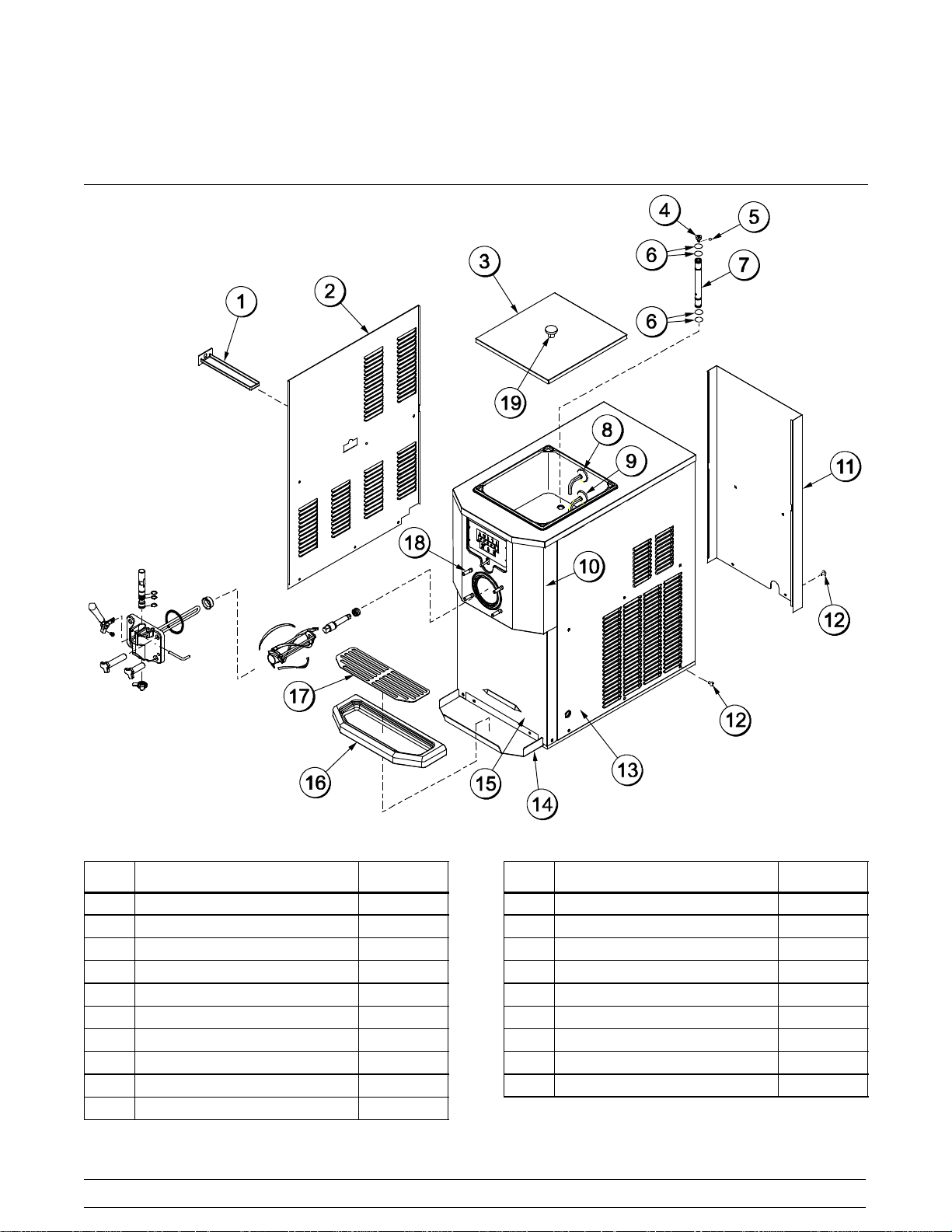
Section 4 Operator Parts Identification
Model 701T
ITEM DESCRIPTION PART NO.
1 PAN-DRIP 11-5/8 LONG 027503
2 PANEL-LEFT SIDE C00009
3 COVER-HOPPER-12 QT C00079
4 ORIFICE 022465-100
5 O-RING-3/8 OD X .070W 016137
6 O-RING-.643 OD X .077W 018572
7 TUBE-FEED 067895
8 PROBE A.-MIX-SQ-MIXLOW X30922
9 PROBE A.-MIX-SQ-MIX OUT X35135
10 PANEL A.-FRONT-UPPER C00026
100907
Figure 1
8
ITEM DESCRIPTION PART NO.
11 PANEL-REAR C00011
12 SCREW-M6.0X1.0X10 RHM-SS C00031
13 PANEL-RIGHT SIDE C00010
14 SHELF-TRAY-DRIP C00024
15 PANEL-FRONT-LOWER C00008
16 TRAY-DRIP-BLACK 067865
17 SHIELD-TRAY-DRIP C00025
18 STUD-NOSE CONE 022822
19 KNOB-MIX COVER 025429
Model 701TOperator Parts Identification
Page 13

Model 701T Single Spout Door and Beater Assembly
Figure 2
ITEM DESCRIPTION PART NO.
1 HANDLE A.-DRAW X56246
2 DOOR A W/BAFFLE X67902-SER
3 VALVE A.-DRAW X58820
4 O-RING-7/8OD X .103W 014402
5 BEARING-FRONT 050216
6 BEATER A.-2.8QT-HELICORE X35466
7 SHAFT-BEATER 033235
8 SEAL-DRIVE SHAFT 032560
Model 701T Operator Parts Identification
ITEM DESCRIPTION PART NO.
9 BLADE-SCRAPER-PLASTIC 035480
10 GASKET-DOOR HT 4"-DOUBLE 048926
11 PIN-HANDLE-SS 055819
12 CAP-DESIGN 014218
13 NUT-STUD-BLACK 2.563 LONG 058764
14 NUT-STUD-BLACK 3.250 LONG 058765
15 O-RING-1/4 ODX .070W 50 015872
16 SCREW-ADJUSTMENT-5/16-24 056332
100907
9
Page 14
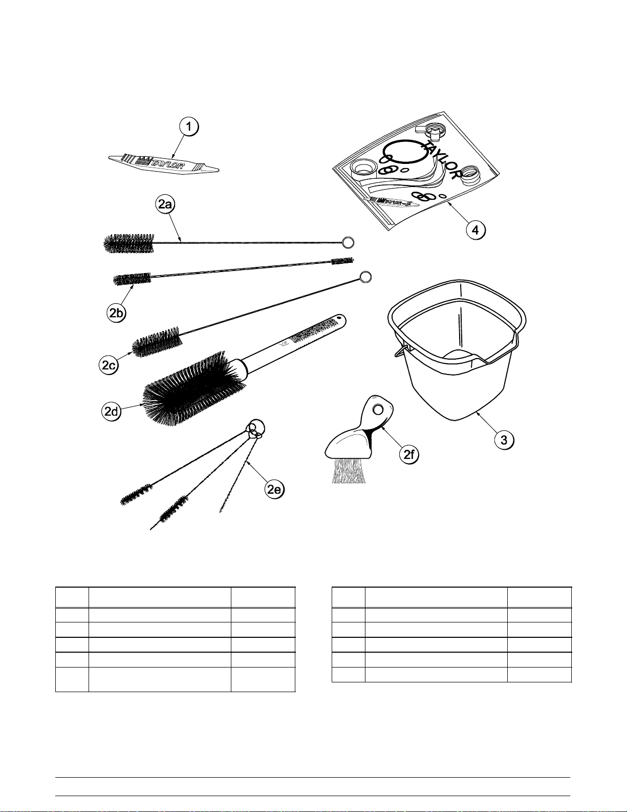
Accessories
ITEM DESCRIPTION PART NO.
1 TOOL-O-RING REMOVAL 048260-WHT
2 KIT A.-BRUSH 1 SPOUT C00005-1
2a BRUSH-REAR·BRG·1IN.DX2IN. C00100
2b BRUSH-DOUBLE·ENDED C00101
2c BRUSH-DRAW·VALVE·
1” X 2” X 17"
100907
C00104
Figure 3
10
ITEM DESCRIPTION PART NO.
2d BRUSH-MIX·PUMP·BODY-3X7 023316
2e BRUSH-SET·LVB C00103
2f BRUSH-END-DOOR-SPOUT 039719
3 PAIL-10 LITERS-GREEN C00173
4 KIT A.-TUNE UP-1 SPOUT C00003-2
Model 701TOperator Parts Identification
Page 15

Section 5 Important: To the Operator
Figure 4
ITEM DESCRIPTION
1 MIX LOW INDICATOR LIGHT
2 MIX OUT INDICATOR LIGHT
3 MIX REFRIGERATIONKEY
4 STANDBY KEY
Model 701T Important: To the Operator
ITEM DESCRIPTION
5 WASH KEY
6 AUTO KEY
7 RESET BUTTON - BEATER MOTOR
8 POWER SWITCH (TOGGLE)
100907
11
Page 16

Symbol Definitions
MIX REF Key
To better communicate in the International arena,
symbols have replaced words on many of our
operator switches, function, and fault indicators.
Your Tekni-Craft equipment is designed with these
International symbols.
The following chart identifies the symbol definitions.
=OFF
=ON
=MIXLOW
= MIX OUT
=MIXREF
= STANDBY
= WASH
=AUTO
When the MIX REF key is pressed, the light comes
on indicating the mix hopper refrigeration system is
operating. The MIX REF function cannot be
cancelled unless the AUTO or STANDBY modes are
cancelled first.
STANDBY Key
The Separate Hopper Refrigeration System (SHR)
and the Cylinder Temperature Retention System
(CTR) are standard features. The SHR incorporates
the use of a separate small refrigeration system to
maintain the mix in the hopper below 4.4°C (40°F) to
assure bacteria control. The CTR works with the
SHR to maintain a good quality product. During long
“No Sale” periods, it is necessary to warm the
product in the freezing cylinder to approximately 1.7
to 4.4°C (35 to 40°F) to prevent over-beating and
product breakdown.
To activate the SHR and CTR, press the STANDBY
key. Remove the air orifice and place the feed tube
(end without the hole) into the mix inlet hole.
Power Switch
When placed in the ON position, the power switch
allows SOFTECH control panel operation.
Indicator Lights
When the MIX LOW light begins to flash, it indicates
that the mix tank has a low supply of mix and should
be refilled as soon as possible. When the MIX OUT
light begins to flash, it indicates that the mix tank
has been almost completely exhausted and has an
insufficient supply of mix to operate the freezer. At
this time, the STANDBY and AUTO modes are
locked out and the freezer shuts down. To initiate
the refrigeration system, add mix to the tank and
press the AUTO key. The freezer will automatically
begin operation.
When the STANDBY key is pressed, the light comes
on, indicating the CTR (Cylinder Temperature
Retention System) has been activated. In the
STANDBY mode, the WASH and AUTO functions
are automatically cancelled. The MIX REF function
is automatically locked in to maintain the mix in the
hopper.
To resume normal operation, press the AUTO key.
When the unit cycles off, the product in the freezing
cylinder will be at serving viscosity. At this time,
place the feed tube (end with the hole) into the mix
inlet hole and install the air orifice.
WASH Key
When the WASH key is pressed, the light comes on.
This indicates beater motor operation. The
STANDBY or AUTO modes must be cancelled first
to activate the WASH mode.
12
Model 701TImportant: To the Operator
Page 17

AUTO Key
Adjustable Draw Handle
When the AUTO key is pressed, the light comes on.
This indicates that the main refrigeration system has
been activated. In the AUTO mode, the WASH or
STANDBY functions are automatically cancelled.
The MIX REF function is automatically locked in to
maintain the mix in the mix hopper.
Note: An indicating light and an audible tone will
sound whenever a mode of operation has been
pressed. To cancel any function, press the key
again. The light and mode of operation will shut off.
Beater Motor Reset Button
The reset button is located on the right side of the
unit. The reset protects the beater motor from an
overload condition. If an overload occurs, the reset
mechanism will trip. To properly reset the freezer,
press the AUTO key to cancel the cycle. Turn the
power switch to the OFF position. Press the reset
button firmly.
Do not use metal objects to press the
reset button. Failure to follow this instruction
may result in electrocution.
Turn the power switch to the ON position. Press the
WASH key and observe the freezer's performance.
The beater motor should turn the drive shaft in a
clockwise direction (from the operator end) without
binding.
If the beater motor is turning properly, press the
WASH key to cancel the cycle. Press the AUTO key
to resume normal operation. If the freezer shuts
down again, contact a service technician.
The Model 701T features an adjustable draw handle
to provide the best portion control. The draw handle
should be adjusted to provide a flow rate of 142 to
213 g (5 to 7-1/2 oz.) of product per 10 seconds. To
INCREASE the flow rate, turn the screw
CLOCKWISE. Turn the screw COUNTERCLOCKWISE to DECREASE the flow rate.
Figure 5
100930
Model 701T Important: To the Operator
13
Page 18

Feed Tube Assembly
The feed tube assembly serves two purposes. One end of the tube has a hole and the other end does not.
1. Normal Operation
During normal operation, the end of the feed
tube with the hole is placed into the mix inlet
hole. Every time the draw handle is raised, new
mix and air from the hopper flow into the
freezing cylinder. This keeps the freezing
cylinder properly loaded and maintains overrun.
2. Long “No Sale” Periods
During long “No Sale” periods, the unit can be
placed into the Standby mode. This maintains
product temperatures below 4.4°C (40°F) in
both the hopper and the freezing cylinder, and
helps prevent over-beating and product
breakdown.
To place the unit into the Standby mode, press
the STANDBY key. Remove the air orifice.
Lubricate the o-rings located on the end of the
feed tube without the hole. Place that end of
the tube into the mix inlet hole. This will prevent
any mix from entering the freezing cylinder.
Note: Theairorificeisusedtometeracertain
amount of air into the freezing cylinder. The air
orifice maintains overrun and allows enough
mix to enter the freezing cylinder after a draw.
100907
Figure 6
ITEM DESCRIPTION PART NO.
1 ORIFICE 022465-100
2 O-RING-3/8 OD X .070 W 016137
3 O-RING-.643 OD X .077 W 018572
4 TUBE FEED *701T 067895
14
Model 701TImportant: To the Operator
Page 19

Section 6 Operating Procedures
The 701T unit stores mix in a hopper. It has a 2.65
liter (2.8 quart) capacity freezing cylinder and a
13.25 liter (14 quart) mix hopper. This unit uses a
feed tube to allow mix to flow into the freezing
cylinder.
We begin our instructions at the point where we
enter the store in the morning and find the parts
disassembled and laid out to air dry from the
previous night's cleaning.
These opening procedures will show you how to
assemble these parts into the freezer, sanitize them,
and prime the freezer with fresh mix in preparation
to serve your first portion.
If you are disassembling the machine for the first
time or need information to get to this starting point
in our instructions, turn to page 23, “Disassembly”,
and start there.
Assembly
Note: When lubricating parts, use an approved food
grade lubricant (example: Taylor Lube).
Fill the inside portion of the seal with 6.4 mm (1/4”)
more lubricant and lubricate the flat side of the seal
that fits onto the rear shell bearing.
Figure 7
Insert the drive shaft into the freezing cylinder, hex
end first, and into the rear shell bearing until the seal
fits securely over the rear shell bearing. Engage the
hex end firmly into the drive coupling. Be sure the
drive shaft fits into the drive coupling without
binding.
MAKE SURE POWER SWITCH IS IN THE
“OFF” POSITION! Failure to follow this instruction
may result in severe personal injury from hazardous
moving parts.
Step 1
Lubricate the groove and shaft portion that comes in
contact with the bearing on the beater drive shaft.
Slide the seal over the shaft and groove until it
snaps into place. DO NOT lubricate the hex end of
the drive shaft.
Model 701T Operating Procedures
15
Figure 8
Page 20

USE EXTREME CAUTION when handling
the beater assembly. The scraper blades are very
sharp and may cause injury.
Step 2
If the blades are in good condition, take one of the
scraper blades and slip it under the hook at the front
of the beater. Wrap the blade around the beater,
following the helix and pushing the blade down onto
the helix as you wrap. At the back end of the beater,
slip the blade under the hook.
Figure 9
Figure 10
Make sure the beater assembly is in position over
the drive shaft. Turn the beater slightly to be certain
that the beater is properly seated. When in position,
the beater will not protrude beyond the front of the
freezing cylinder.
Step 3
Place the large rubber gasket into the groove on the
back side of the freezer door.
Slide the white plastic front bearing over the baffle
rod onto the bearing hub making certain that the
flanged end of the bearing is resting against the
freezer door. Do not lubricate the gasket or the
front bearing.
Repeat this step for the second scraper blade.
Holding the beater securely, slide the beater into the
freezing cylinder about one-third of the way in.
Looking into the freezing cylinder, align the hole at
the rear of the beater with the flats on the end of the
drive shaft.
Slide the beater the remainder of the way into the
freezing cylinder and over the end of the drive shaft.
The beater should fit snugly but not so tightly that
the beater cannot be turned slightly to engage the
drive shaft.
Figure 11
16
Model 701TOperating Procedures
Page 21

Step 4
Slide the three o-rings into the grooves on the draw
valve, and lubricate.
Figure 12
Lubricate the inside of the freezer door spout, top
and bottom, and insert the draw valve from the top
until the draw valve is at the bottom.
Note: This unit features an adjustable draw handle
to provide the best portion control. The draw handle
can be adjusted for different flow rates. See page 13
for more information on adjusting this handle.
Step 6
Insert the baffle rod through the opening in the
beater and seat the door flush with the freezing
cylinder. With the door seated on the freezer studs,
install the handscrews. Tighten equally in a
crisscross pattern to insure the door is snug.
Step 7
Snap the design cap over the end of the door spout.
Figure 13
Step 5
Install the adjustable draw handle. Slide the fork
over the bar in the slot of the draw valve. Secure
with pivot pin.
Figure 14
Figure 15
Step 8
Install the front drip tray and the splash shield under
the door spout.
Figure 16
100907
Model 701T Operating Procedures
17
Page 22

Step 9
Slide two o-rings on one end of the feed tube. Slide
two o-rings on the other end of the feed tube.
Figure 17
Note: Make sure the hole in the air orifice is clean
and is not clogged. If the hole in the air orifice should
become clogged, use soap and hot water to clear
the hole. Do not enlarge the hole in the air
orifice.
Install the air orifice into the hole in the top of the
feed tube (in the end without the small hole on the
side).
Figure 19
Slide the small o-ring into the groove of the air
orifice. Do not lubricate the o-ring.
Figure 18
Step 10
Lay the feed tube (with the air orifice installed) in the
bottom of the mix hopper for sanitizing.
Step 11
Slide the rear drip pan into the hole in the side
panel.
Figure 20
100907
18
Model 701TOperating Procedures
Page 23

Sanitizing
Step 1
Prepare an approved 100 PPM sanitizing solution
(examples: 9.5 liters [2-1/2 gal.] of Kay-5R or 7.6
liters [2 gal.] of Stera-SheenR). USE WARM
WATER AND FOLLOW THE MANUFACTURER'S
SPECIFICATIONS.
Step 2
Pour the sanitizing solution over all the parts in the
bottom of the mix hopper and allow it to flow into the
freezing cylinder.
Figure 23
Figure 21
Note: You have just sanitized the mix hopper and
parts; therefore, be sure your hands are clean and
sanitized before going on in these instructions.
Step 3
While the solution is flowing into the freezing
cylinder, take particular care to brush-clean the mix
level sensing probe on the front wall and the bottom
of the hopper, the mix hopper, and the feed tube.
Figure 24
Step 4
Place the power switch in the ON position.
Figure 22
Model 701T Operating Procedures
19
Figure 25
100907
Page 24

Step 5
Press the WASH key. This will cause the sanitizing
solution in the freezing cylinder to agitate. Allow it to
agitate for five minutes.
Step 7
Once the sanitizer stops flowing from the door
spout, raise the draw handle. Press the WASH key,
cancelling the beater motor operation.
Figure 28
Figure 26
Step 6
With an empty pail beneath the door spout, draw off
all of the sanitizing solution.
Figure 27
Note: Be sure your hands are clean and
sanitized before continuing these instructions.
Step 8
Lubricate the mix feed tube o-rings located on the
end of the tube with the small hole on the side.
Stand the mix feed tube in the corner of the mix
hopper.
Figure 29
100907
20
Model 701TOperating Procedures
Page 25

Priming
Step 1
Place an empty pail beneath the door spout and
lower the draw handle. Pour two gallons (7.6 liters)
of fresh mix into the hopper and allow it to flow into
the freezing cylinder. This will force out any
remaining sanitizing solution. When full strength mix
is flowing from the door spout, raise the draw
handle.
Note: Use only fresh mix when priming the
freezer.
Step 3
Press the AUTO key. When the unit cycles off, the
product will be at serving viscosity.
Figure 31
Step 2
When the mix stops bubbling down into the freezing
cylinder, install the mix feed tube (the end with the
hole) with the air orifice installed in the mix inlet hole
in the mix hopper.
Figure 30
Step 4
Fill the hopper with fresh mix. As the mix level
comes in contact with the mix level sensing probe on
the rear wall of the hopper, the MIX LOW light will
shut off.
Note: The MIX REF light will come on, indicating
the mix refrigeration system is maintaining mix in the
mix hopper.
Step 5
Place the mix hopper cover in position.
Closing Procedure
To disassemble your unit, the following items will be
needed:
S Two cleaning pails
S Sanitized stainless steel rerun can with lid
S Necessary brushes (provided with freezer)
S Cleaner
S Single service towels
Model 701T Operating Procedures
21
Page 26

Draining Product From the
Freezing Cylinder
Step 1
Press the AUTO key, cancelling compressor and
beater motor operation.
Press the MIX REF key, cancelling the mix hopper
refrigeration system.
Step 2
Remove the hopper cover and take it to the sink for
cleaning.
Rinsing
Step 1
Pour 7.6 liters (two gallons) of cool clean water into
the mix hopper. With the brushes provided, scrub
the mix hopper, the mix inlet hole and the mix level
sensing probe.
Step 2
With a pail beneath the door spout, press the WASH
key and lower the draw handle.
Step 3
Drain all the rinse water from the freezing cylinder.
When the water stops flowing from the door spout,
raise the draw handle and press the WASH key,
cancelling the WASH mode.
Repeat this procedure until the rinse water being
drawn from the freezing cylinder is clear.
Step 3
If local health codes permit the use of rerun,
place a sanitized, NSF approved stainless steel
rerun container beneath the door spout. Press the
WASH key and lower the draw handle. Drain the
remaining product from the freezing cylinder and mix
hopper. When the flow of product stops, press the
WASH key and raise the draw handle. Place the
sanitized lid on the rerun container and place it in
the walk-in cooler.
Note: If local health codes DO NOT permit the
use of rerun, the product must be discarded.
Drain the product into a mix pail and properly
discard it.
Step 4
Remove the assembled mix feed tube and take it to
the sink for further disassembly and cleaning.
ALWAYS FOLLOW LOCAL HEALTH CODES.
Cleaning
Step 1
Prepare an approved 100 PPM cleaning solution
(examples: 9.5 liters [2-1/2 gal.] of Kay-5R or 7.6
liters [2 gal.] of Stera-SheenR). USE WARM
WATER AND FOLLOW THE MANUFACTURER'S
SPECIFICATIONS.
Step 2
Pour the cleaning solution into the mix hopper.
Step 3
While the solution is flowing into the freezing
cylinder, brush clean the mix hopper, mix level
sensing probes and the mix inlet hole.
Step 4
Press the WASH key. This will cause the cleaning
solution in the freezing cylinder to be agitated.
Step 5
Place an empty pail beneath the door spout and
lower the draw handle. Draw off all of the solution.
Step 6
Once the cleaning solution stops flowing from the
door spout, raise the draw handle and press the
WASH key, cancelling the WASH mode.
22
Model 701TOperating Procedures
Page 27

Disassembly
Step 1
Be sure the power switch is in the OFF position.
Make sure no lights are lit on the control panel.
Step 2
Remove the handscrews, freezer door, beater,
beater shoes, scraper blades, and drive shaft from
the freezing cylinder. Take these parts to the sink for
cleaning.
Step 3
Remove the feed tube, the front drip tray and the
splash shield.
Brush Cleaning
Make sure all brushes provided with the freezer are
available for brush cleaning.
Note: To remove the o-rings, use a single service
towel to grasp the o-ring. Apply pressure in an
upward direction until the o-ring pops out of its
groove. With the other hand, push the top of the
o-ring forward and it will roll out of the groove and
can be easily removed. If there is more than one
o-ring to be removed, always remove the rear o-ring
first. This will allow the o-ring to slide over the
forward rings without falling into the open grooves.
Step 4
Return to the freezer with a small amount of
cleaning solution. With the black bristle brush, brush
clean the rear shell bearing at the back of the
freezing cylinder.
Step 1
Prepare a sink with an approved cleaning solution
(examples: Kay-5R or Stera-SheenR). USE WARM
WATER AND FOLLOW THE MANUFACTURER'S
SPECIFICATIONS. If another approved cleaner is
used, dilute according to label instructions.
IMPORTANT: Follow label directions, as too
STRONG of a solution can cause parts damage,
while too MILD of a solution will not provide
adequate cleaning. Make sure all brushes provided
with the freezer are available for brush cleaning.
Step 2
Removethe seal from the drive shaft.
Step 3
From the freezer door remove the gasket, front
bearing, pivot pin, adjustable draw handle, design
cap, and the draw valve. Remove all o-rings.
Figure 32
Step 5
Remove the rear drip pan from the side panel and
take it to the sink for cleaning.
Note: If the drip pan is filled with an excessive
amount of mix, refer to the Troubleshooting Guide.
Step 6
Thoroughly brush clean all disassembled parts in the
cleaning solution, making sure all lubricant and mix
film is removed. Take particular care to brush clean
the hole for the draw valve in the freezer door. Place
all cleaned parts on a clean, dry surface to air dry
overnight.
Step 7
Wipe clean all exterior surfaces of the freezer.
Model 701T Operating Procedures
23
Page 28

Section 7 Important: Operator Checklist
During Cleaning and Sanitizing
ALWAYS FOLLOW LOCAL HEALTH CODES.
Cleaning and sanitizing schedules are governed
by federal, state, or local regulatory agencies,
and must be followed accordingly. If the unit
has a “Standby mode”, it must not be used in
lieu of proper cleaning and sanitizing
procedures and frequencies set forth by the
ruling health authority. The following check
points should be stressed during the cleaning
and sanitizing operations.
CLEANING AND SANITIZING MUST BE
PERFORMED DAILY.
Troubleshooting Bacterial Count
Mix the rerun with fresh mix in a ratio of 50/50
when refilling the hopper throughout the day.
j 6. On a designated day of the week, run the mix
as low as feasible and discard it after closing.
This will break the rerun cycle and reduce the
possibility of high bacteria and coliform
counts.
j 7. Properly prepare the cleaning and sanitizing
solutions. Read and follow label directions
carefully. Too strong of a solution may
damage the parts and too weak of a solution
will not do an adequate job of cleaning or
sanitizing.
j 8. The temperature of the mix in the mix hopper
and walk-in cooler should be below 40_F
(4.4_C).
Regular Maintenance Checks
j 1. Thoroughly clean and sanitize machine
regularly, including complete disassembly and
brush cleaning.
j 2. Use all brushes supplied for thorough
cleaning. The brushes are specially designed
to reach all mix passageways.
j 3. Use the white bristle brush to clean the mix
inlet hole which extends from the mix hopper
down to the rear of the freezing cylinder.
j 4. Use the black bristle brush to thoroughly
clean the rear shell bearing located at the rear
of the freezing cylinder. Be sure to have a
generous amount of cleaning solution on the
brush.
j 5. IF LOCAL HEALTH CODES PERMIT THE
USE OF RERUN, make sure the mix rerun is
stored in a sanitized, covered stainless steel
container and used the following day. DO
NOT prime the machine with rerun. When
using rerun, skim off the foam and discard.
j 1. Replace scraper blades that are nicked or
damaged. Before installing the beater
assembly, be certain that scraper blades are
properly attached to the helix.
j 2. Check the rear shell bearing for signs of wear
(excessive mix leakage in rear drip pan) and
be certain it is properly cleaned.
j 3. Using a screwdriver and cloth towel, keep the
rear shell bearing and the female hex drive
socket clean and free of lubricant and mix
deposits.
j 4. Dispose of o-rings and seals if they are worn,
torn, or fit too loosely, and replace with new
ones.
j 5. Follow all lubricating procedures as outlined in
“Assembly”.
24
Model 701TImportant: Operator Checklist
Page 29

j 6. If your machine is air cooled, check the
condensers for accumulation of dirt and lint.
Dirty condensers will reduce the efficiency
and capacity of the machine. Condensers
should be cleaned monthly with a soft brush.
Never use screwdrivers or other metal probes
to clean between the fins.
Note: For machines equipped with an air
filter, it will be necessary to vacuum clean the
filters on a monthly schedule.
Caution: Always disconnect
electrical power prior to cleaning the
condenser. Failure to follow this instruction
may result in electrocution.
j 7. If your machine is equipped with an auxiliary
refrigeration system, check the auxiliary
condenser for accumulation of dirt and lint.
Dirty condensers will reduce the refrigeration
capacity of the mix hopper. Condensers must
be cleaned monthly with a soft brush. Never
use screwdrivers or other metal probes to
clean between the fins.
Caution: Always disconnect
electrical power prior to cleaning the
condenser. Failure to follow this instruction
may result in electrocution.
j 8. If your machine is water cooled, check the
water lines for kinks or leaks. Kinks can occur
when the machine is moved back and forth for
cleaning or maintenance purposes.
Deteriorated or cracked water lines should be
replaced only by an authorized Teckni-Craft
distributor.
Winter Storage
If the place of business is to be closed during the
winter months, it is important to protect the freezer
by following certain precautions, particularly if the
building is subject to freezing conditions.
Disconnect the freezer from the main power source
to prevent possible electrical damage.
On water cooled freezers, disconnect the water
supply. Relieve pressure on the spring in the water
valve. Use air pressure on the outlet side to blow out
any water remaining in the condenser. This is
extremely important. Failure to follow this
procedure may cause severe and costly damage to
the refrigeration system.
Your local Taylor Distributor can perform this winter
storage service for you.
Wrap detachable parts of the freezer such as
beater, blades, drive shaft, and freezer door, and
place them in a protected dry place. Rubber trim
parts and gaskets can be protected by wrapping
them with moisture-proof paper. All parts should be
thoroughly cleaned of dried mix or lubrication which
attract mice and other vermin.
Model 701T Important: Operator Checklist
25
Page 30

Section 8 Troubleshooting Guide
PROBLEM PROBABLE CAUSE REMEDY PAGE
REF.
1. No product is being
dispensed with draw valve
open and the machine in
the AUTO mode.
2. The product is too stiff. a. The viscosity needs
3. The product is too soft. a. Viscosity needs
a. Freeze-up in mix inlet
hole.
b. Beater motor out on reset. b. Reset the freezer.
c. The beater is rotating
counterclockwise from the
operator end.
d. The circuit breaker is off
or the fuse is blown.
e. There is inadequate mix in
the mix hopper.
f. The mix feed tube is
installed upside down.
adjustment.
adjustment.
a. Call service technician to
adjust the mix hopper
temperature.
c. Contact service technician
to correct rotation to
clockwise from operator
end.
d. Turn the breaker on, or
replace the fuse.
e. Fill the mix hopper with
mix.
f. Turn the mix feed tube
over, so the end of the
tube with the hole in it is
installed in the mix inlet
hole.
a. Contact service
technician.
a. Contact service
technician.
---
13
---
---
21
21
---
---
4. The mix in the mix hopper
is too cold.
b. Not enough air space
around unit. (Air cooled
units)
c. Worn scraper blades. c. Replace regularly.
d. Dirty condenser (A/C) d. Clean monthly.
e. Mix is out of date. e. Use only fresh mix.
f. Loss of water. (W/C) f. Locate cause of water
a. The temperature is out of
adjustment.
26
b. Allow for adequate air flow
across the condenser.
loss and correct.
a. Call service technician to
adjust the mix hopper
temperature.
1/ 7
29
25
--25
---
Model 701TTroubleshooting Guide
Page 31

PROBLEM PROBABLE CAUSE REMEDY PAGE
REF.
5. The mix in the mix hopper
is too warm.
6. The drive shaft is stuck in
the drive coupling.
7. The freezing cylinder walls
are scored.
a. The temperature is out of
adjustment.
b. The mix hopper cover is
not in position.
c. The MIX REF light is not
lit.
d. Warm mix was added to
the mix hopper.
a. Rounded corners of drive
shaft, coupling, or both.
b. Mix and lubricant collected
in the drive coupling.
a. The beater assembly is
bent.
b. The front bearing is
missing or worn on the
freezer door.
c. Powdered mix was not
thoroughly mixed.
a. Call service technician to
adjust the mix hopper
temperature.
b. Place the cover in
position.
c. Press the MIX REF key.
d. The temperature of the
mix should be below
4.4_C(40_F).
a. Call service technician to
correct cause, and to
replace the necessary
components. Do not
lubricate the hex end of
the drive shaft.
b. Brush clean the rear shell
bearing area regularly.
a. Call service technician to
repair or replace the
beater and to correct the
cause of insufficient mix in
the freezing cylinder.
b. Install or replace the front
bearing.
c. Make sure powdered mix
is thoroughly dissolved.
---
21
12
24
---
23
---
16
---
8. Excessive mix leakage
into the rear drip pan.
9. Excessive mix leakage
from door spout.
a. Missing or worn drive
shaft seal on drive shaft.
b. The rear shell bearing is
worn.
a. Missing or worn draw
valve o-rings.
b. Inadequate lubrication of
a. Install or replace regularly.
b. Call service technician to
replace rear shell bearing.
a. Install or replace regularly.
b. Lubricate properly.
15 / 29
---
17 / 29
17
draw valve o-rings.
c. Wrong type of lubricant is
being used (example:
c. Use the proper lubricant
(example: Taylor Lube).
15
petroleum base lubricant).
Model 701T Troubleshooting Guide
27
Page 32

PROBLEM PROBABLE CAUSE REMEDY PAGE
REF.
10. No freezer operation after
pressing the AUTO key.
11. Product is not feeding into
the freezing cylinder.
a. Unit is unplugged. a. Plug into wall receptacle.
b. The circuit breaker is off
or the fuse is blown.
c. The beater motor is out on
b. Turn the breaker on, or
replace the fuse.
c. Reset the freezer.
reset.
a. Inadequate level of mix in
the mix hopper.
b. The mix inlet hole is
frozen up.
a. Fill the mix hopper with
mix.
b. The mix hopper
temperature needs
adjustment. Call service
technician.
---
---
13
21
---
28
Model 701TTroubleshooting Guide
Page 33

Section 9 Parts Replacement Schedule
PART DESCRIPTION EVERY
3MONTHS
Drive Shaft Seal X
Scraper Blade X
Freezer Door Gasket X
Front Bearing X
Draw Valve O-Ring X
Feed Tube O-Ring X
Air Orifice O-Ring X
Brush-Rear Bearing 1” x 2” (Black Bristle) Inspect & Replace
Brush-Double-Ended Inspect & Replace
Brush-Draw Valve 1” x 2” x 17” (White Bristle) Inspect & Replace
Brush-Mix Pump Body 3” x 7” (White Bristle) Inspect & Replace
EVERY
6MONTHS
if Necessary
if Necessary
if Necessary
if Necessary
ANNUALLY
Minimum
Minimum
Minimum
Minimum
Brush-Set LVB (White Bristle) Inspect & Replace
if Necessary
Brush-End-Door Spout (White Bristle) Inspect & Replace
if Necessary
Minimum
Minimum
Model 701T Parts Replacement Schedule
29
Page 34

Section 10 Parts List
REMARKS
CLASS
QTY. WARR.
NUMBER
DESCRIPTION PART
+GUIDE-DRIP SEAL 028992 1 000
+NUT-BEARING 028991 1 000
+WASHER-BEARING LOCK 012864 1 000
ACCUMULATOR-COPPER 2"DIA 10"LG 047062 1 103 RECEIVER A.-REFRIGAC *701T*
ARM A.-IDLER *356* X64892 1 103
ARMAFLEX 3/8 ID X 1/4WALL 020896-27 1 000 R50322
ARMAFLEX 7/8 ID X 3/8WALL 020899-19 1 000 R50332
ARMAFLEX 5/8 ID X 3/8WALL 032650-11 1 000 R50330
BEARING-FRONT 050216 1 000
BEARING-REAR SHELL-NICKEL 031324 1 000
100907
BEARING-SHAFT-THRUST *701T* 067900 1 000
Parts List Model 701T
BEARING-UNIT-SHELL*701T* 067894 1 103
BEATER A.-2.8QT-HELICORE X35466 1 103
+BLADE-SCRAPER-PLASTIC 13-1/4L 035480 4 000
BELT-POLY V-620J10-AX62 067954 1 000
BLOCK-TERMINAL 2P L1,N 039421 1 103
30
BLOCK-TERMINAL 3P .25 SPADE 057201 1 103
BLOCK-TERMINAL 7P GREEN 024156 1 103 C00081-40
BOARD-LOGIC-GEN 2.10-W/SEL DI X36641SER2 1 212
BOARD-POWER-GEN 1 & 2 X32326-SER 1 212
BOLT-IDLER PULLEY *358* 046039 1 103
BRUSH -SEE KIT A.-BRUSH --- 1 000 SEE KIT A.-BRUSH
BUMPER-RUBBER 026984 4 000
BUSHING-SPLIT43/64ID X 7/8OD 027691 2 103
CABLE-RIBBON-PWR/RLY *C706*60 056295 1 103
CAP-DESIGN 1.010"ID-6 POINT 014218 1 000
CARD-CHECKOUT C00067 1 000
CLIP-PANEL-LOWERFRONT *701T* C00073 2 000
+CAPACITOR-START 60UF-220/275V 047703 1 103
+RELAY-START-COMPRESSOR-PL35G 055358 1 103 DANFOSS COMP
+CAPACITOR-RUN 35UF/370V 029439 1 103
+CAPACITOR-START 145-175UF/220V 012901 1 103 C00052-40
+RELAY-START-COMPRESSOR 051957-12 1 103
COMPRESSOR PL35G 055187-27 1 512 AUX COMPX55187SER2 COMPLETE KIT
COMPRESSOR CS14K6E-PFJ-238 052396-40 1 512
CONDENSER-AC 7X6X1.25-2 ROW 027155 1 103 AUX
CONDENSER-AC 15LX14HX2.59T-3RW 046558 1 103 MAIN
Page 35

CLASS
QTY.PART
NUMBER
DESCRIPTION REMARKSWARR.
COUPLING-3/8FS X 1/4FS 031791 1 103 LINE A.-DISCHARGE *701T*
CORE-SCHRADER VALVE-TEFLON 037047 1 103
Model 701T
COVER A.-HOPPER *701T* C00079 1 103
+KNOB-MIX COVER 025429 1 103
DECAL-DEC-TEKNI-CRAGT*701T* C00062 1 000
DECAL-INST-CLN HPR-CHINESE 019029-CH 1 000
DECAL-TROUBLESHOOT-CHINESE 038374-CH 1 000
DIAGRAM-WIRING *701T* 067928-40 1 000
DOOR A.-W/BAFFLE *701T* X67902-SER 1 103
+BEARING-FRONT 050216 1 000
+CAP-DESIGN 1.010"ID-6 POINT 014218 1 000
+GASKET-DOOR HT 4"-DOUBLE 048926 1 000
+HANDLE A.-DRAW X56246 1 103
+O-RING-1/4OD X .070W 50 DURO 015872 1 000
+NUT-JAM SS 029639 1 000
+SCREW-ADJUSTMENT-5/16-24 *602* 056332 1 103
+PIN-HANDLE-SS *C602* 055819 1 103
31
+VALVE A.-DRAW *C602* X55820 1 103
+O-RING-7/8 OD X .103W 014402 3 000
DRYER-FILTER-HP62-3/8 X 1/4S 048901 1 000 LINE A.-DRYER *701T*
DRYER-CAP. TUBE .021 ID X 9FT 055522 1 000
DVD-OPS TRAIN VIDEO*701T* C00069 1 000
EYELET-RESET BUTTON 013739 1 103
FASTENER-CLIP 1/4-20 U-TYPE 045865 20 000
FUSE-.063A-250V-5X20MM-SLO BLO 051272 1 103
GASKET-BASE PAN *701T* 067864 1 000
GASKET-DOOR HT 4"-DOUBLE 048926 1 000
GUARD-POWER SWITCH 034830 1 103
INTERLOCK A.-DOOR X65658 1 103
SPRING-INTERLOCK DOOR 065409 2 000
SWITCH-REED*DOOR INTERLOCK*6 056771 1 103
JACK A.-FLAVORBURST X56353 1 103
KIT A.-BRUSH*1SPOUT**701T* C00005-1 1 000
BRUSH-REAR BRG 1"D X 2"LG X C00100 1 000
BRUSH-DBL END-PUMP&FEED TUBE C00101 1 000
BRUSHES-SET LVB C00103 1 000
BRUSH-DRAW VALVE 1"OD X 2"X1 C00104 1 000
101014
Parts List
BRUSH-MIX PUMP BODY-3" X 7" 023316 1 000
Page 36

CLASS
QTY.PART
NUMBER
DESCRIPTION REMARKSWARR.
O-RING-3/8 OD X .070W 016137 1 000
O-RING-.643 OD X .077W 018572 4 000
INSTRUCTION-FEED TUBE-TUNE-U 056200-21 1 000
BLADE-SCRAPER-PLASTIC 13-1/4 035480 2 000
INSTRUCTION-BARREL-TUNE-UP 056200-22 1 000
SEAL-DRIVE SHAFT 032560 1 000
BEARING-FRONT 050216 1 000
CAP-DESIGN 1.010"ID-6 POINT 014218 1 000
GASKET-DOOR HT 4"-DOUBLE 048926 1 000
INSTRUCTION-DOOR-TUNE-UP 056200-24 1 000
O-RING-1/4OD X .070W 50 DUR 015872 1 000
O-RING-7/8 OD X .103W 014402 3 000
TOOL-O-RING REMOVAL-FREEZER 048260-WHT 1 000
BRUSH-END-DOOR-SPOUT-SS-HT 039719 1 000
Parts List Model 701T
KIT A.-MOTOR-FAN X62253-27 1 103
KIT A.-TUNE UP*1SPOUT**701T* C00003-2 1 000
KIT A.-TUBE-FEED X56200-21 1 000
KIT A.-BARREL X56200-22 1 000
KIT A.-DOOR X56200-24 1 000
32
KIT-MOUNTING-COMPRESSOR 047704 1 000 DANFOSS
KIT-MOUNTING-COMPRESSORCS 052197 1 000 MAIN
LABEL-DOOR-MOVE PART-CHINESE 032749-CH 1 000
LABEL-SW-POWER-OFF/ON-SYMBOLS 052632 1 000
LABEL-WARN-COVER-CHINESE 051433-CH 3 000
LUBRICANT-TAYLOR 4 OZ. 047518 1 000
MAN-OPER*701T* C00068 1 000
MOTOR-1.0 HP 067893-40 1 212
+CAPACITOR-RUN 15UF/440V 062009 1 103
+CAPACITOR-START 108-130UF/370V 059999 1 103
MOTOR-FAN 95.3 CFM 2700 RPM --- * --- SEE KIT A.-MOTOR
MOTOR-FAN 100W 220-240V 50HZ 047178-34 1 103
+CAPACITOR-RUN 4UF/440V 051785 1 103
+BOOT-CAPACITOR-INSULATING 031314 1 000
+FAN-5 BLADE 12"PUSH 32DEG CCW 047279 1 103
NUT-STUD-BLACK 2.563 LONG 058764 2 103
NUT-STUD-BLACK 3.250 LONG 058765 2 103
ORIFICE 022465-100 1 103
+O-RING-3/8 OD X .070W 016137 1 000
Page 37

CLASS
QTY.PART
NUMBER
DESCRIPTION REMARKSWARR.
PAN-DRIP 11-5/8 LONG 027503 1 103
PANEL A.-FRONT-UPPER *701T* C00026 1 103
Model 701T
PANEL-FRONT-LOWER *701T* C00008 1 103
PANEL-REAR *701T* C00011 1 103
PANEL-SIDE *701T*L C00009 1 103
PANEL-SIDE *701T*R C00010 1 103
PAIL-10 LITERS-GREEN C00173 1 000
PLATE-DEC *701T* C00080 1 103
PROBEA.-MIX*SQUARE* X30922 1 103
+DISC-PROBE *SQ HOLE* 030965 1 103
+SPACER-PROBE *SQ HOLE* 030966 1 103
PROBEA.-MIX*SQUARE* X35135 1 103
+DISC-PROBE *SQ HOLE* 030965 1 103
+SPACER-PROBE *SQ HOLE* 030966 1 103
PROBE A.-THERMISTOR X31602 1 103
PROBE A.-THERMISTOR/RESISTOR X50717 1 103
PULLEY-IDLER 3.00PD X 1.49" 054826 1 103
33
+BOLT-IDLER PULLEY *358* 046039 1 103
+BRACKET-IDLER ARM *358* 045912 1 103
+SPRING-EXTENSION.500X.063X4.00 046046 1 103
PULLEY-10J-1.062 PD-5/8BORE 067930 1 103
PULLEY-10J-13.00 PD-5/8 BORE 067892 1 103
RELAY-3 POLE-20A-208/240 50/60 066795-33 1 103 REPLACES 012725-33
SANITIZER-STERA SHEEN-GREEN C00002 1 000
SCREW-SHOULDER 1/2DX2"L 046048 1 000
SHAFT-BEATER 033235 1 103
+SEAL-DRIVE SHAFT 032560 1 000
SHELF-DRIP *701T* C00025 1 103 DRIP SHIELD
SHELF-DRIP TRAY *701T* C00024 1 103 SHELF
SHELL A.-INSULATED *701T* X67866 1 512
+STUD-NOSE CONE 022822 4 103
SHROUD-CONDENSER *701T* C00071 1 103
STARTER-1 PHASE 4 TO 6.5 AMP 066794-27J 1 103
OVERLOAD-THERMAL-2P-4.5/7.5A 047150-27K 1 103 NLA
STARTER-1 PHASE-4.5 TO 7 A 041950-27K 1 103 USE 066794-27j
STUD-NOSE CONE 022822 4 103
SWITCH A.-DRAW *C706* X56147 1 103
Parts List
ARM A.-DRAW *C706* X56253 1 103
Page 38

CLASS
QTY.PART
NUMBER
DESCRIPTION REMARKSWARR.
E-RING 3/16 .335 OD 1500-18PP 049178 1 000
INSULATOR-SWITCH1/64 ARMITE 029099 2 000
NUT-4-40 HEX-SS 038623 2 000
PIN-PIVOT 015478 1 103
SCREW-4-40X1 SLTD ROUND 028890 2 000
SPRING-RETURN-LEFT-SELFCLOSE 041660 1 103
SPRING-RETURN-RIGHT-SELF CLOSE 041661 1 103
SWITCH-LEVER-SPDT-10A-125-250V 028889 2 103
+GUARD-POWER SWITCH 034830 1 103
+LABEL-SW-POWER-OFF/ON-SYMBOL 052632 1 000
SWITCH A.-POWER *701T* C00127 1 103 FRONT PANEL
SWITCH-PRESSURE 440 PSI-SOLDER 048230 1 103 LINE A.-DISCHARGE *701T*
TEE-1/4S-COPPER 003949 1 000 LINE A.-SUCTION-DANFOSS *701T*
TOOL-O-RING REMOVAL-FREEZER 048260-WHT 1 000
Parts List Model 701T
TRAY-DRIP *701T* BLACK 067865 1 103
TUBE-FEED *701T* 067895 1 103
+O-RING-.643 OD X .077W 018572 4 000
VALVE-ACCESS 1/4FL X 1/4SOLDER 044404 1 103 LINE A.-SUCTION-DANFOSS *701T*
34
VALVE-ACCESS-1/4 MFLX1/4 S-90 047016 1 103 USE ON PL35G
VALVE-ACCESS-1/4MFL X 3/8ODSDR 053565 1 103 LINE A.-ACCESS *701T*
VALVE-ACCESS-1/4MFL X 3/8ODSDR 053565 1 103 LINE A.-DISCHARGE *701T*
VALVE-EPR 1/4S 022665 1 103 LINE A.-SUCTION-DANFOSS *701T*
+BOOT-VALVE-EXPANSION 050900 1 000
VALVE-EXP-AUTO-1/4SX1/4 FPT 046365 1 103
Page 39

701T
067928-40
Rev. 10/10
 Loading...