

Page 1

Shake Freezer
Model 5456
Operating Instructions
5/96
Page 2

Complete this page for quick reference when service is required:
Taylor Distributor:
Address:
Phone:
Service:
Parts:
Date of Installation:
Information found on data plate:
Model Number:
Serial Number:
Electrical Specs: Voltage Cycle
Phase
Maximum Fuse Size: Amps
Minimum Wire Ampacity: Amps
Part Number:
E May, 1996 Taylor
All rights reserved.
Page 3

Table of Contents
______________________________________________________________________________
Section 1 To the Installer 1............................................
Air Cooled Units 1.......................................................
Electrical Connections 1.................................................
Section 2 To the Operator 2...........................................
Compressor Warranty Disclaimer 2.......................................
Section 3 Safety 3....................................................
Section 4 Operator Parts Id en t ificatio n 4...............................
Section 5 Important: To the Operator 8.................................
Master Switch (Power Switch) 8..........................................
Adjustment Knob 8......................................................
Reset Button 8.........................................................
Indicator Light -- “Mix Low” 8.............................................
Indicator Light -- “Mix Out” 8..............................................
Section 6 Operating Procedures 9.....................................
Freezing Cylinder Assembly 9............................................
Air/Mix Pump Assembly 13................................................
Sanitizing 16............................................................
Priming 17..............................................................
Syrup System 19.........................................................
Closing Procedures 22...................................................
Draining Product From T he Freezing Cylinder 22............................
Rinsing 22..............................................................
Cleaning 22.............................................................
Disassembly 23..........................................................
Brush Cleaning 23.......................................................
Discard Syrups, Clean and Sanitize the Syrup Lines and Syrup Tanks 24.......
Section 7 Troubleshooting Guide 25....................................
Section 8 Important: Operator Checklist 29..............................
During Cleaning and Sanitizing: 29.........................................
Troubleshooting Bacterial Count 29........................................
Regular Maintenance Checks 29...........................................
Air/Mix Pump Checklist 30................................................
Winter Storage 30........................................................
Section 9 Parts Replacement Schedule 31...............................
Section 10 Parts List 32.................................................
Note: Continuing research results in steady improvements; therefore, info rmation
in this manual is subject to change without notice.
Taylor Model 5456
Page 4

Notes:
Taylor Model 5456
Page 5
Section 1 To the Installer
This machine is designed for indoor use only.
DO NOT install the machine in an area where a
water jet couldbe used to clean or rinse the machine. Failure
to follow thisinstruction may result in serious electricalshock.
Water Connections
(Water Cooled Units Only)
An adequate cold water supply must be provided with a hand
shut-off valve. On the rear of the unit, two 3/8” I.P.S. water
connections for inlet and outlet have been provided for easy
hook-up. 3/8” inside diameter water lines should be
connected to the machine. (Flexiblelines are recommended,
if local codes permit.) Depending on local water conditions,
it may be advisable to install a water strainer to prevent
foreign substances from clogging the automatic water valve.
There will be only one water “in” and one water “out”
connection. DO NOT install a hand shut-off valve on the
water “out” line! Water should always flow in this order: first,
through the automatic water valve; second, through the
condenser; and third, through the outlet fitting to an open
trap drain.
Electrical Connections
Each freezer requires one power supply. Check the data
label on the freezer for fuse, circuit ampacity and electrical
specifications. Refer to the wiring diagram provided inside of
the electrical box, for proper power connections.
In the United States, this equipment is intended to be
installed in accordance with the National Electrical Code
(NEC), ANSI/NFPA 70 --1987. The purpose of the NEC code
is the practical safeguarding of persons and property from
hazards arising fromthe use of electricity. This code contains
provisions considered necessary for safety. Compliance
therewith and proper maintenancewill result in an installation
essentially free from hazard!
In all other areas of the world, equipment should be installed
in accordance with the existing local codes. Please contact
your local authorities.
Stationary appliances which are not equipped with a power
cord and a plug or other device to disconnect the appliance
from the power source must have an all--pole disconnecting
device with a contact gap of at least 3 mm installed in the
external installation.
CAUTION: THIS EQUIPMENT MUST BE
PROPERLY GROUNDED! FAILURE TO DO SO CAN
RESULT IN SEVERE PERSONAL INJURY FROM
ELECTRICAL SHOCK!
Beater rotation must be clockwise as viewed looking into the
freezing cylinder.
Air Cooled Units
Air cooled units require a minimum of 3” (76 mm) of clearance
around all sides of the freezer and 12” (305 mm) on top to
allow for adequate air flow across the condensers. Failure to
allow adequate c learance can reduce the refrigeration
capacity of the freezer and possibly cause permanent
damage to the compressors.
Taylor Model 54561
NOTE: The following procedures should be performed by a
trained service technician.
To correct rotation on a three-phase unit, interchange any
two incoming power supply lines at freezer main terminal
block only.
To correct rotation on a single-phase unit, change the leads
inside the beater motor. (Follow diagram printed on motor.)
Electrical connections are made directly to the terminal
block. The terminalblock is provided in the splice box located
behind the right side panel.
050831
Page 6

Section 2 To the Operator
The freezer you have purchased has been carefully
engineered and manufactured to give you dependable
operation. The Taylor Model 5456, when properly operated
and cared for, will produce a consistent quality product. Like
all mechanical products, this machine will require cleaning
and maintenance. A minimum amount of care and attention
is necessary if the operating procedures outlined in this
manual are followed closely.
This Operator’s Manual should be read before operating or
performing any maintenance on your equipment.
Your Model 5456 will NOT eventually compensate and
correct for any errors during the set-up or primingoperations.
Thus, the initial assembly and priming procedures are of
extreme importance. It is strongly recommended that
personnel responsible for the equipment’s operation, both
assembly and disassembly, sit down together and go
through these procedures in order to be properly trained and
to make sure that no misunderstandings exist.
In the event you should require technical assistance, please
contact your local authorized Taylor Distributor.
If the crossed out wheeled bin symbol is affixed to
this product, it signifies that this product is compliant with the
EU Directive as well as other similar legislation in effect after
August 13, 2005. Therefore, it must be collected separately
after its use is completed, and cannot be disposed as
unsorted municipal waste.
The user is responsible for returning the product to the
appropriate collection facility, as specified by your local code.
For additional information regarding applicable local laws,
please contact the municipal facility and/or local distributor.
Compressor Warranty Disclaimer
The refrigeration compressor(s) on this machine are
warranted for the term indicated on the warranty card
accompanying this machine. However, due to the Montreal
Protocol and the U.S. Clean Air Act Amendments of 1990,
many new refrigerants are being tested and developed, thus
seeking their way into the service industry. Some of these
new refrigerants are being advertised as drop-in
replacements for numerous applications. It should be noted
that, in the event of ordinary service to this machine’s
refrigeration system, only the refrigerant specified on the
affixed data label should be used. The unauthorized use
of alternate refrigerants will void your compressor warranty.
It will be the owner ’s responsibility to make this fact known to
any technician he employs.
It should also be noted that Taylor does not warrant the
refrigerant used in its equipment. For example, if the
refrigerant is lost during the course of ordinary service to this
machine, Taylor has no obligation to either supply or provide
its replacement either at billable or unbillable terms. Taylor
does have the obligation to recommend a suitable
replacement if the original refrigerant is banned, obsoleted,
or no longer available during the five year warranty of the
compressor.
Taylor will continue to monitor the industry and test new
alternates as they are being developed. Should a new
alternate prove, through our testing,thatitwould be accepted
as a drop-in replacement, then the above disclaimer would
become null and void. To find out the current status of an
alternate refrigerant as it relates to your compressor
warranty, call the local Taylor Distributoror the TaylorFactory.
Be prepared to provide the Model/Serial Number of the unit
in question.
Taylor Model 54562
070115
Page 7
Section 3 Safety
We at Taylor are concerned about the safety of the operator
when he or she comes in contact with the freezer and its
parts. Taylor has gone to extreme efforts to design and
manufacture built-in safety features to protect both you and
the service technician. As an example, warning labels have
been attached to the freezer to further point out safety
precautions to the operator.
IMPORTANT -- Failure to adhere to the following safety
precautions may result in severe personal injury. Failure
to comply with these warnings may damage the machine
and its components. Component damage will result in
part replacement expense and service repair expense.
S DO NOT allow untrained personnel to operate
this machine.
S DO NOT operate the freezer unless all service
panels and access doors are restrained with
screws.
S DO NOT remove the door, beater, scraper blades,
drive shaft or torque rotor shaft unless the power
switch is in the “OFF” position.
To Operate Safely:
DO NOT operate the freezer without reading this
operator’s manual. Failureto follow this instruction may result
in equipment damage, poor freezer performance, health
hazards, or personal injury.
S DO NOT operate the freezer unless it is properly
grounded.
S DO NOT attempt any repairs unless the main
power supply to the freezer has been
disconnected.
S DO NOT operate the freezer with larger fuses
than specified on the freezer data label.
Failureto follow these instructions may result in electrocution
or damage to the machine. Contact your local authorized
Taylor Distributor for service.
DO NOT usea water jet to clean or rinse the freezer.
Failure to follow this instruction may result in serious
electrical shock.
Failure to follow these instructions may result in
contaminated product or severe personal injury to fingers or
hands from hazardous moving parts.
S DO NOT put objects or fingers in the door spout
or the spinner housing.
S USE EXTREME CAUTION when removing the
beater assembly.
Failure to follow these instructions may result in
contaminated product or personal injury from blade contact.
This freezer is designed to operate indoors, under normal
ambient temperatures of 70_-- 7 5 _F(21_-- 2 4 _C). The
freezers have successfully performed in high ambient
temperatures of 104_F(40_C) at reduced capacities.
DO NOT obstruct air intake and discharge openings: 3”
(76 mm) minimum air space on all sides, and 12” (305 mm)
minimum air space on top. Failure to follow this instruction
may cause poor freezer performance and damage to the
machine.
This freezer must be placed on a level surface.
Failure to comply may result in personal injury or equipment
damage.
Taylor Model 54563
NOISE LEVEL: Airborne noise emission does not exceed 78
dB(A) when measured at a distance of 1.0 meter from the
surface of the machine and at a height of 1.6 meters from the
floor.
070115
Page 8
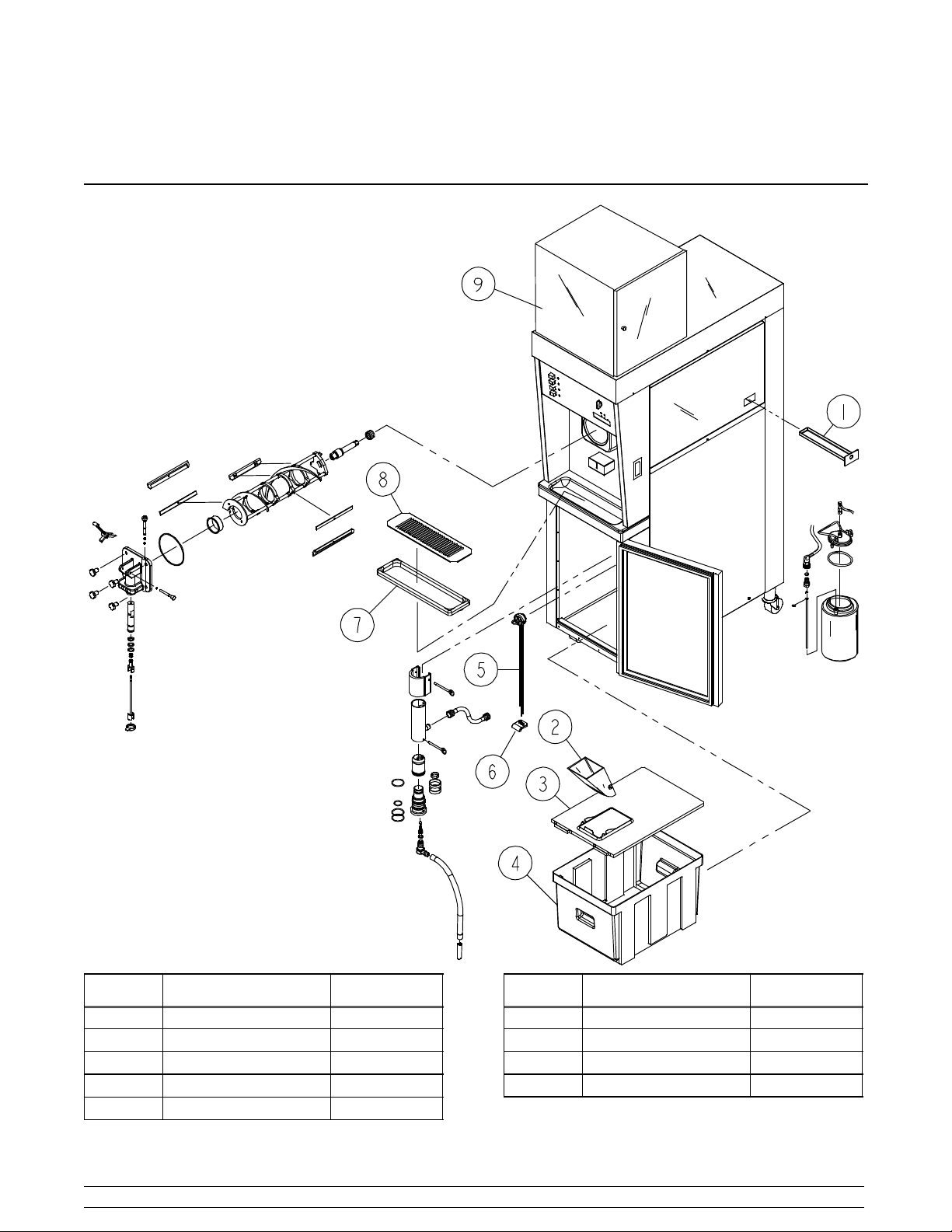
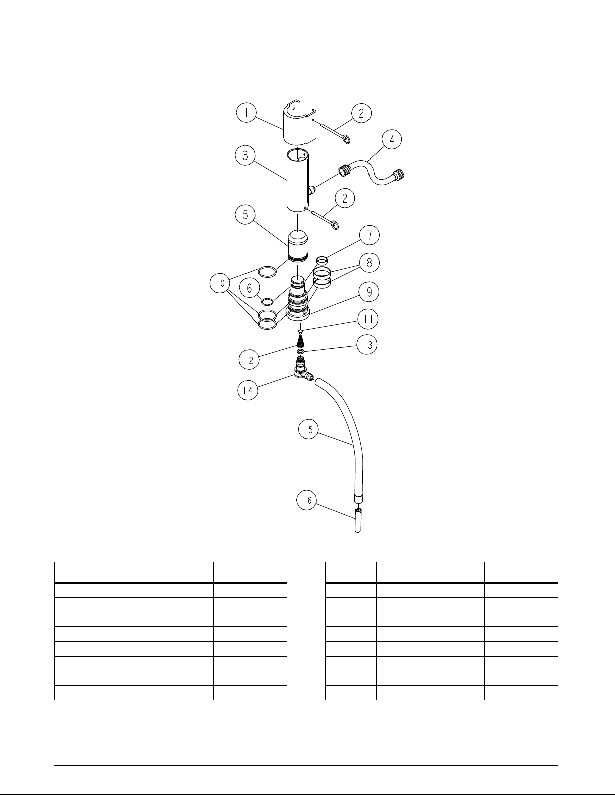
Section 4 Operator Parts Identification
Model 5456 ExplodedView
Item Description Part Number
1 Drip Pan 027503
2 Mix Funnel 036637
3 Cover-MixTank X38726
4 Mix Tank 020275
5 Probe - Mix X35981
Taylor Model 54564
Item Description Part Number
6 Boot - Mix Cover 037200
7 Drip Tray 020157
8 Splash Shield 022765
9 Kit A.-Syrup Cabinet X46941
Page 9
Refer to Parts List on PageNO TAG when ordering above
parts.
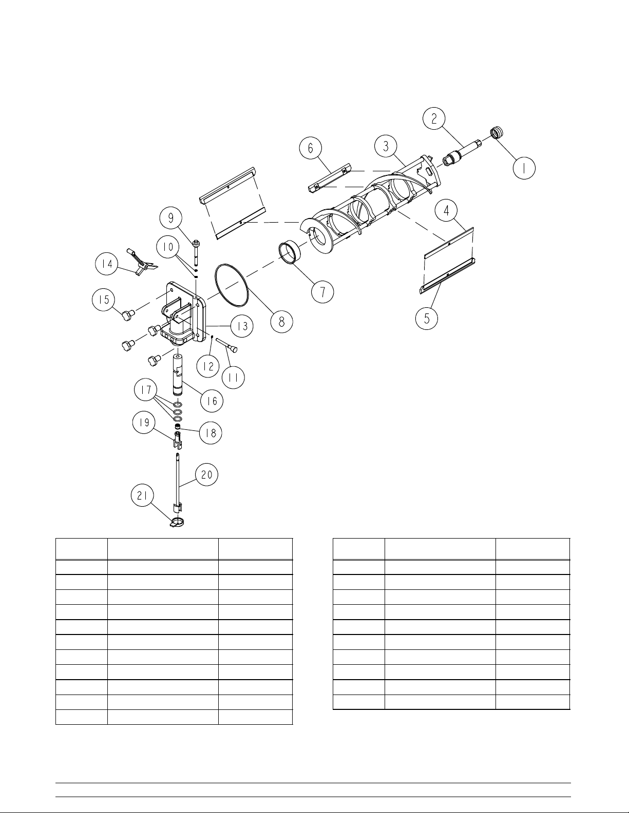
Beater and Door Assemblies
Item Description Part Number
1 Seal-Drive Shaft 032560
2 Beater Shaft 032790
3 Beater X46234
4 Clip-Scraper Blade 046238
5 Scraper Blade-Plastic 046237
6 Scraper Blade-7-3/8 L 045054
7 Front Bearing 013116
8 Door Gasket 016672
9 Prime Plug 028805
10 O-Ring - Prime Plug 016137
11 Pivot Pin X22820
Taylor Model 54565
Item Description Part Number
12 O-Ring - 5/16 OD 016272
13 Door-Freezer X33101
14 Handle-Draw Valve 034003
15 Stud Nut 034034
16 Draw Valve X33102
17 O-Ring 1-1/16 OD 020571
18 Seal-Spinner Shaft 036053
19 Driven Spinner 036054
20 Spinner Blade X34065
21 Restrictor Cap 033107
Refer to Parts List on PageNO TAG when ordering above
parts.
Page 10
Pump Parts
Item Description Part Number
1 Pump Cap 021276-9
2 Retaining Pin 021276-8
3 Pump Cylinder 022345-1
4 Flare Line 038299
5 Piston 032733
6 O-Ring - 1-3/8 OD 018664
7 Check Ring - 1-1/4 OD 033215
8 CheckRing-2OD 020050
Taylor Model 54566
Item Description Part Number
9 Valve Body X33451
10 O-Ring - 2-1/8 OD 020051
11 Poppet 022473
12 Spring 022456
13 O-Ring - 13/16 OD 021278
14 Inlet Elbow 022502-4
15 Vinyl Tube 020945-22
16 Counter Weight 020452
Refer to Parts List on PageNO TAG when ordering above
parts.
Page 11
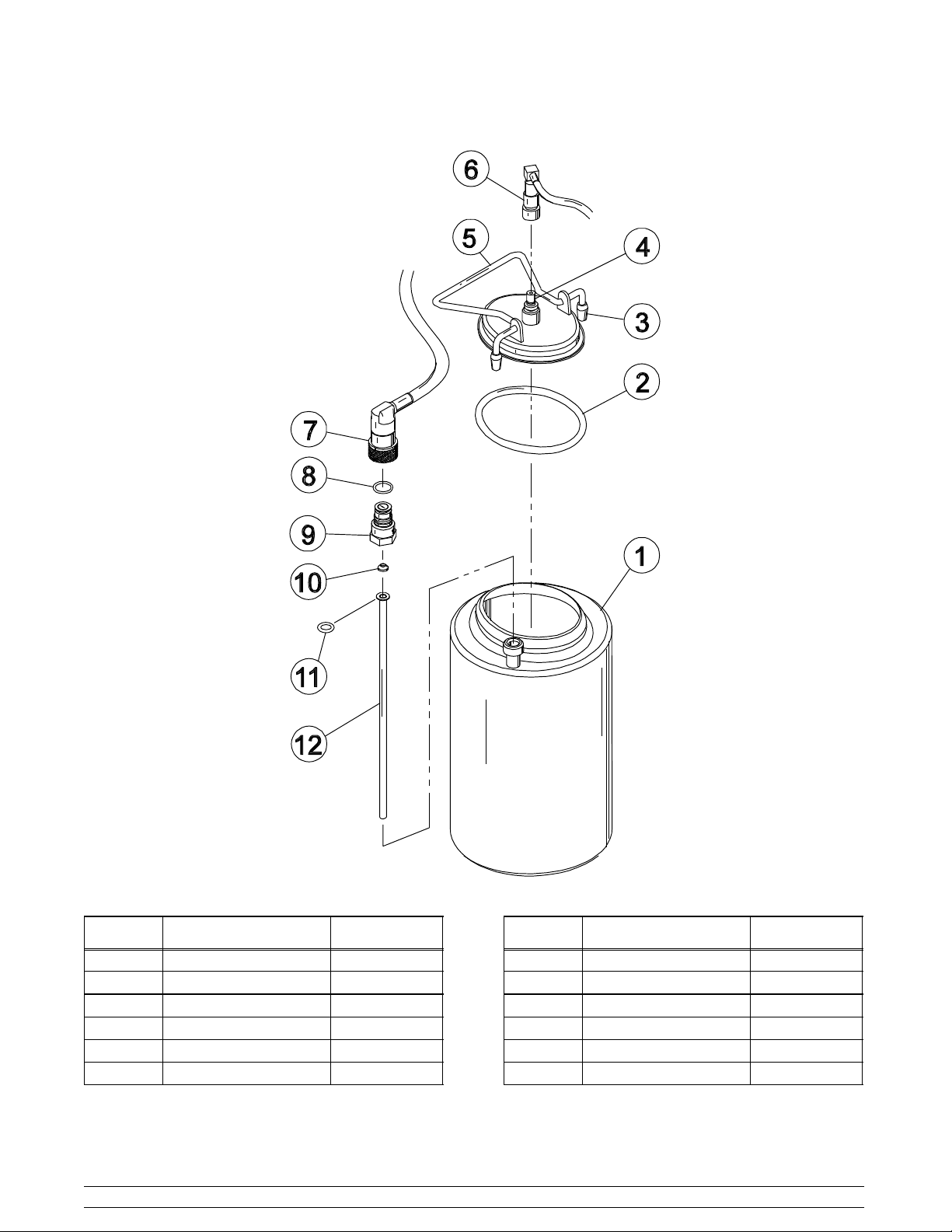
Syrup Tank
Item Description Part Number
1 Tank-Syrup 035759
2 Gasket 016037
3 Rubber Tip 024261
4 CO2 Plug 021077
5 Cover 035759-1
6 Socket - CO2 021524
Taylor Model 54567
Item Description Part Number
7 Socket - Liquid 021026
8 O-Ring 016030
9 Liquid Plug 021081
10 Flare Washer 018595
11 O-Ring 018550
12 Dip Tube 020577-4
Refer to Parts List on PageNO TAG when ordering above
parts.
Page 12
Section 5 Important: To the Operator
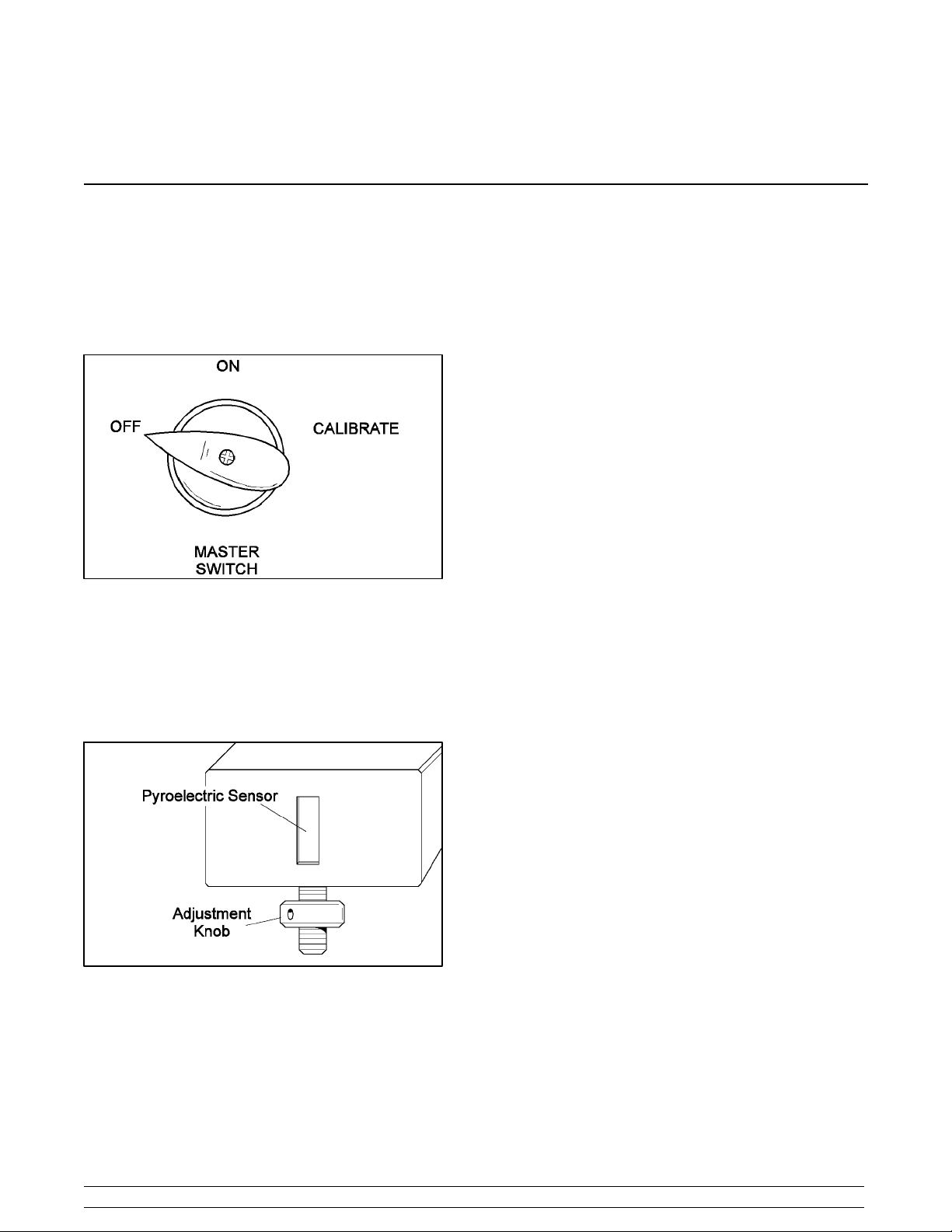
Master Switch (Power Switch)
The master switch controls the machine operation. The left
position is the “OFF” position. The center position is the“ON”
position and allows SOFTECH operation. The right position
is the “CALIBRATE” position, and allows syrup to flow
through the syrup lines for the calibration procedure.
Adjustment Knob
Located under the pyroelectric sensor (beneath the shake
door), is a cup fill adjustment knob. The operator can adjust
the sensing eye to determine the correct level of shake
dispensed into the cup.
Reset Button
The reset button is located on the right side of the machine.
The reset protects the beater motor from an overload
condition. If an overload occurs, the reset mechanism will
trip. To properly reset the freezer, place the master switch in
the “OFF” position. Press the reset button firmly. Place the
master switch in the “WASH” position and observe the
freezer’s performance. Once satisfied, place the unit back in
the “AUTO” mode.
IMPORTANT: Do notuse metal objects to press the reset
button.
Indicator Light -- “Mix Low”
Located on the front of the machine is a mix level indicating
light. When the light is flashing, it indicates that the mix
reservoir (tank) has a low supply of product and should be
refilled as soon as possible. Neglecting to add mix when the
light comes on will cause the machine to sway and may
eventually cause damage to the beater assembly and
freezer door.
Taylor Model 54568
Indicator Light -- “Mix Out”
Also located on the font of the machine is a mix out indicating
light. When the light is flashing, it indicates that the mix
reservoir (tank) is empty and the mix supply needs
replenishing. To prevent damage to the unit, refrigeration
discontinues automatically when the mix out indicator lights.
Page 13
Section 6 Operating Procedures
Freezing Cylinder Assembly
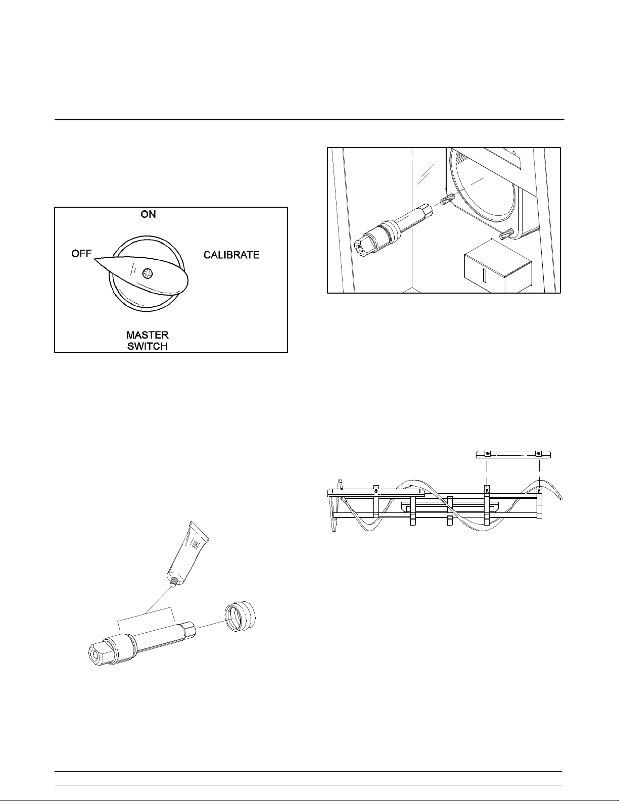
MAKE SURE THE MASTER SWITCH (POWER
SWITCH) IS IN THE “OFF” POSITION.
Figure 3.
Step 2.
Install the beater assembly.Firstcheck the scraper blades for
any nicks or signs of wear. If any nicks are present, replace
the blades.
Figure 1.
Note: When lubricating parts, use an approved food grade
lubricant (example: Taylor Lube).
Step 1.
Install the drive shaft. Lubricate the groove and shaft portion
that come in contact with the bearing on the beater drive
shaft. Slide the seal over the small end of the shaft and
engage into the groove on the shaft. Fill the inside portion of
the s eal with 1/4” more lubricant and evenly lubricate the end
of the seal that fits onto the rearshell bearing. Apply an even
coat of lubricant to the shaft. DO NOT lubricate the square
end.
If the blades are in good condition, install scraper blade clips
on the two front scraper blades. Place the rear scraper blade
(shorter blade) over the two rear holding pins on the beater
assembly.
Figure 2.
Insert the drive shaft through the rear shell bearing in the
freezing cylinder and engage the square end firmly into the
gear box coupling.
Taylor Model 54569
Figure 4.
Note: The holes in the scraper blade must fit securely over
the pins to prevent costly damage.
Holding the rear blade on the beater, slide the beater
assembly into the freezing cylinder until the entire blade is
inside. Install the middle scraper blade over the middle
holding pin. Slide the beater assembly in further and install
the front scraper blade over the front holding pin. Slide the
beater assembly the rest of the way into the freezing cylinder.
Rotate and insert the beater assembly in position over the
drive shaft. When properly seated over the drive shaft, the
beater assembly will not protrude beyond the front of the
freezing cylinder.
Page 14
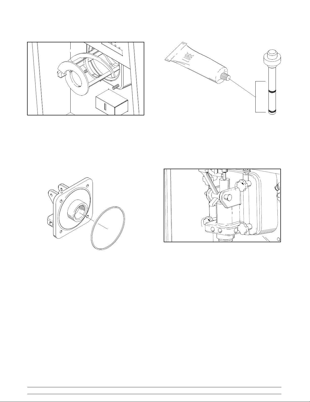
Figure 5.
Figure 7.
Insertthe prime plug into the hole in the top of the freezerdoor
and push down.
Step 3.
Assemble the freezerdoor.Place the freezer door gasketinto
the groove on the back of the freezer door. Slide the front
bearing over the door hub so that the flanged edge is against
the door. DO NOT lubricate the gasket or bearing.
Figure 6.
Slide the two o-rings into the grooves on the prime plug.
Apply an even coat of lubricant to the o-rings and shaft.
Step 4.
Install the freezer door. Position the freezer door on the four
studs on the front of the freezing cylinder. Install the
handscrews. Tighten equally in a criss-cross pattern to
insure that the door is snug.
Figure 8.
Step 5.
Assemble the draw valve spinner assembly.Inspect the draw
valve o-rings for cuts or nicks and replace them as needed.
If the draw valve o-rings are in good condition, slide the three
o-rings into the grooves of the draw valve and lubricate.
Taylor Model 545610
Page 15
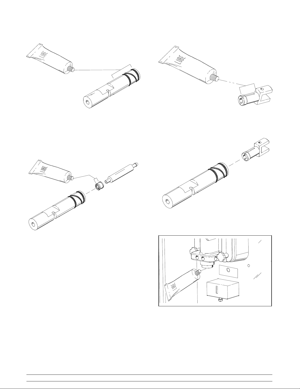
Figure 9.
Lubricate the spinner shaft seal and place it on the
installation end of the “seal installation/removal tool”. Using
the “seal installation/removal tool”, insert the spinner shaft
seal into the bottom of the draw valve as far as it will go. The
spinner shaft seal should fall into the seal groove located
inside the draw valve cavity, and remain in place after
removing the “seal installation/removal tool”.
Figure 10.
Note: Inspect to see that the spinner shaft seal is correctly
installed in the groove. A worn, missing, or improperly
installedspinnershaft seal will cause productleakage out the
top of the draw valve.
Place an even coat of lubricant onto the smaller end of the
driven spinner.
Figure 11.
By squeezing the split end together, insert the driven spinner
through the metal opening of the draw valve until it snaps into
place.
Figure 12.
Step 6.
Lubricate the inside of the freezer door spout, top and
bottom.
Taylor Model 545611
Figure 13.
Install the draw valve spinner assembly.Insert the draw valve
from the bottom until the slot in the draw valve which accepts
the draw handle c omes into view.
Page 16
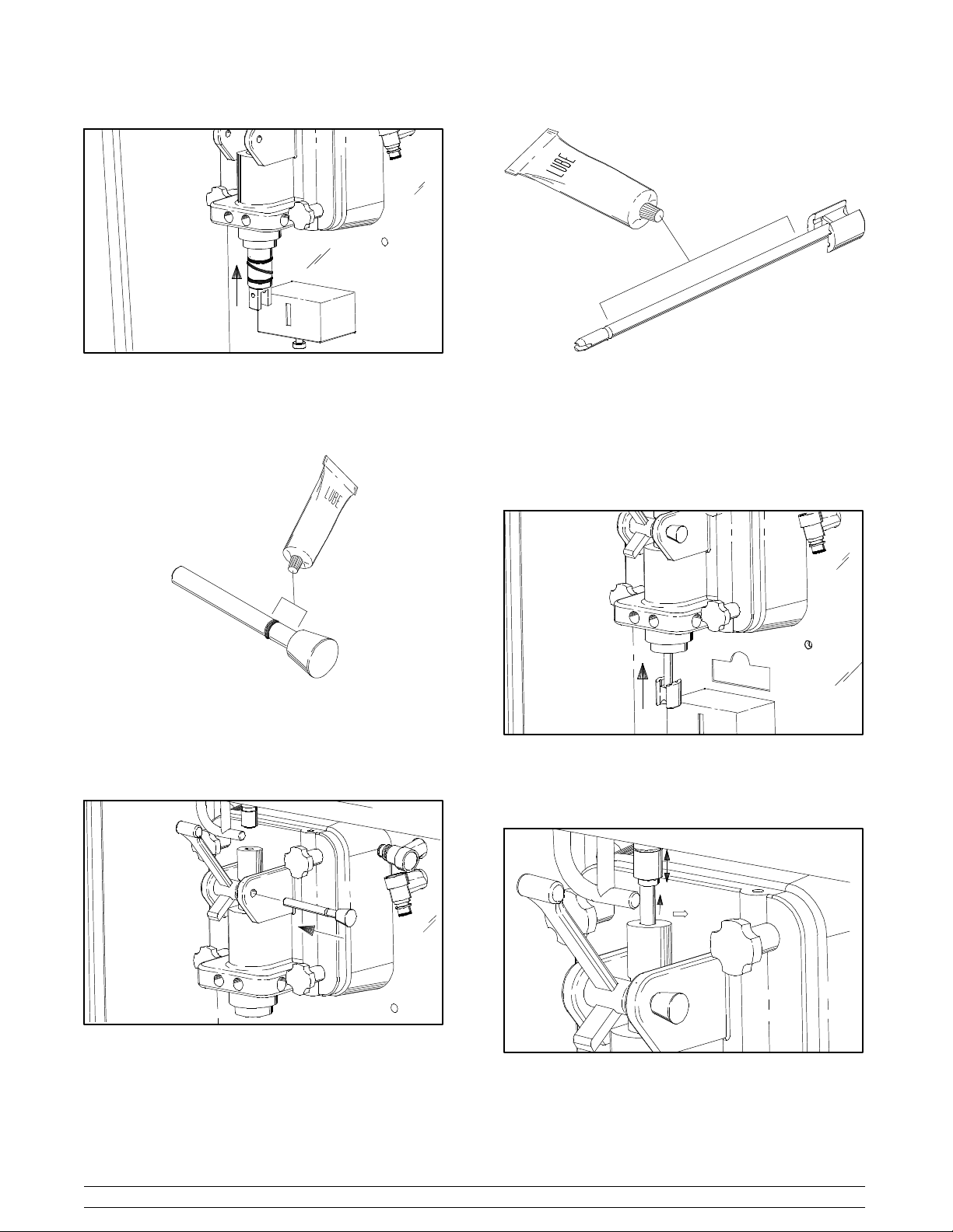
Figure 14.
Step 7.
Install and lubricate the pivot pin o-ring.
Figure 15.
Install the draw handle. With the stopping tab of the draw
handle facing down,slide the fork of the draw handle into the
slot of the draw valve. Secure the draw handle with the pivot
pin.
Figure 17.
Insert the spinner blade shaft from the bottom,into the center
of the driven spinner, and up through the draw valve cavity
until the shaft appears at the top of the draw valve. The
spinner blade must be lined and engaged to the driven
spinner at the bottom. This allows the spinner shaft to raise
high enough to be engaged into the spinner coupling at the
top.
Figure 18.
Raise the locking collar of the spinner coupling and insert the
spinner shaft into the cavity of the coupling until the locking
collar can drop into the locked position.
Figure 16.
Step 8.
Install the spinner blade. Lubricate the shaft of the spinner
blade up to the groove.
Taylor Model 545612
Figure 19.
Step 9.
Snap the restrictor cap over the end of the door spout.
Page 17

Figure 20.
Step 10.
Install the rear drip pan through the side panel.
Step 2.
Assemble the valve body. Slide the two large and one small
o-ring,and the two large and one small check band, into their
respective grooves on the valve body.
Figure 23.
Note: Check bands have two smooth surfaces. A concave
shape indicates an incorrect assembly. Turn the check band
inside out to correctly expose the flat surface.
Figure 21.
Air/Mix Pump Assembly
Step 1.
Assemble the piston. Slide the o-ring into the groove of the
piston.
Figure 22.
Figure 24.
Step 3.
Assemble the mix inlet fitting. Slide the o-ring into the groove
on the mix inlet fitting, and thoroughly lubricate.
Figure 25.
Taylor Model 545613
Page 18

Attach the spring and poppet to the end of the mix inlet fitting.
The spring must be securely fastened and notallowed to float
freely.
Figure 26.
Note: The spring and rubber poppet act as a pressure relief
valve to prevent a pressure build up in the freezing cylinder.
Figure 28.
Step 5.
Lightly lubricate the inside of the pump cylinder at the bottom
with a paper thin layer of lubricant.
Step 4.
Lightly lubricate the inside wall of the piston with a paper thin
layer of lubricant.
Figure 27.
Insert the narrow end of the valve body into the open end of
the piston
Figure 29.
Insert the already assembled piston and valve body into the
bottom of the pump cylinder.
Figure 30.
Taylor Model 545614
Page 19

Note: The drive hole in the piston must be visible through the
drive hole opening in the pump cylinder and the aligning ball
located at the base of the valve body mustbe positioned into
the notch at the bottom of the pump cylinder.
Step 6.
Insert the mix inlet fitting into the hole in the base of the valve
body.
Figure 31.
Figure 33.
Step 8.
Secure the air/mix pump. Place the pump cap over thepump
cylinder. The cross holes of the pump cap must be on top.
Secure the pump parts into position by sliding the retaining
pin through the cross holes located at the bottom of the pump
cylinder.
Figure 32.
Step 7.
Assemble the suction line and the flare line. Attach the mix
suction line to the barbed end of the mix inlet fitting and attach
the weight to the free end.
Figure 34.
Align the drive hole in the piston to the ball crank of the motor
reducer. At the same time, align the locating pin on the face
plate with the small hole at the top of the pump cylinder.
Slide the pump collar upward into the grooves on the side of
thefaceplate.
Attach one end of the flare line to the threaded fitting on the
lower side of the pump cylinder and allow the other end to
hang freely.
Taylor Model 545615
Figure 35.
Page 20

Secure the air/mix pump in place by slipping the retaining pin
through the cross holes of the pump cap.
Figure 36.
Note: Alignment of the air/mix pump is extremely important.
Severe and costly damage may occur if it is not properly
aligned.
Sanitizing
Step 1.
Prepare two gallons (7.6 liters) of an approved 100 PPM
sanitizing solution (example: Kay-5) with WARM WATER
ACCORDING TO THE MANUFACTURER’S SPECIFICATIONS in a mix pail. Place the mix pail of sanitizing solution
inside the mix cabinet.
Figure 38.
Step 5.
Turn the master switch to the “on” position.
Step 2.
Connect the free end of the flare line to the threaded fitting on
the mix feed tube.
Step 3.
Insert the free end ofthe suction line into the pail of sanitizing
solution.
Figure 37.
Step 4.
Place an empty mix pail beneath the door spout and raise the
prime plug.
Figure 39.
Step 6.
Press the words PUMP/PRIME and WASH. This will cause
the sanitizing solution to be pumped into the freezing cylinder
and become agitated by the beater assembly.
Figure 40.
Step 7.
When a steady stream of sanitizing solution is flowing from
the bleed port in the bottom of the freezer door, pull down the
draw handle, and draw off all of the sanitizing solution.
Taylor Model 545616
Page 21

Figure 41.
This process will effectively sanitize the bleed port and the
door spout in the freezer door.
Step 8.
When all the sanitizing solution has been drained, lift up the
draw handle and press the words PUMP/PRIME and WASH
to cancel beater and pump operation.
Priming
Step 1.
Sanitize the mix tank, mix tank cover, mix probe and the
funnel. Place the mix tank and cover in the mix cabinet.
Figure 43.
Step 3.
Place the free end of the suction line down into the mix tank.
Figure 44.
Step 4.
Installthe funnel. Fill the tank with freshmix and close the mix
cabinet door.
Figure 42.
Step 2.
Insert the prongs of the mix probe inside the mix tank and
connect the mix probe into the socket receptacle.
Taylor Model 545617
Figure 45.
Page 22

Step 5.
Place an empty mix pail beneath the door spout and pull
down the draw handle. With the prime plug still in the “up”
position, press the word PUMP/PRIME. This will allow the
mix to be pumped through the freezing cylinder and force out
any remaining sanitizer. When full strength mix is flowing
from the door spout, lift up the draw handle.
Figure 46.
Figure 48.
Step 8.
Press the word PUMP/PRIME to activate the pump motor.
After12 s econds, press theword PUMP/PRIME to cancel the
pump motor operation.
Step 9.
Assemble the shake cup holder. Position the slots of the clip
over the hooks located on the inside of the cup holder. Pull
the clips tightly into place. Install the assembled shake cup
holder.
Figure 47.
Step 6.
Continue the pump operation until a steady stream of mix is
flowing from the bleed port in the bottom of the freezer door.
Once the steady stream of mix has been established,
discontinue the pump operation by pressing the word
PUMP/PRIME.
Step 7.
Once the stream of mix stops flowing from the bleed port,
push the prime plug down.
Taylor Model 545618
Figure 49.
Step 10.
Press the word AUTO. When the unit cycles off, the product
will be at serving consistency.
Page 23

Figure 51.
Figure 50.
Note: Because this unit is portion controlled, all four flavors
must be used with syrup. This will prevent over-filling of the
cup and over-pressurizing of the freezing cylinder.
Syrup System
Two main objectives in your opening procedures must be to:
1. Fill the syrup tanks.
2. Calibrate the syrup flow. This must be checked daily
to insure a high quality shake.
Discard the syrup weekly and flush the syrup lines at least
once a week. This will prevent the syrup from clogging the
lines and will break the bacteria chain.
The syrup tanks can be placed in a separate compartment.
The air lines and syrup lines are color spiral wrapped. Be
sure to match the color wrapped air and syrup line to the
correct flavor syrup tank.
Disconnect the syrup line after you have disconnected the air
line.
Figure 52.
Remove the syrup tank from the compartment. Remove the
syrup tank lid by lifting up on the locking lever. Fill the syrup
tank with syrup to the indicating mark on the label. DO NOT
overfill the tanks.
Note: Vanilla and strawberry syrup lines use restrictors at
the syrup tank quick disconnect connection to maintain
proper calibration. Use only single strength syrup that is
free of pulp and seeds.
Unscrew the quick disconnect from the elbow portion of the
syrup line. Make sure the o-ring rests on the end of the quick
disconnect fitting. Place the restrictor on top of the o-ring and
screw the quick disconnect back onto the syrup line.
Step 1.
Filling the syrup tanks. Pull back on the collar of the quick
disconnect fitting for the air line. Allow the air pressure to
dissipate from the syrup tank.
Taylor Model 545619
Figure 53.
Replace the tank lid. Match and connect the spiral wrapped
syrup line to the syrup tank. Connect the air line to the syrup
tank.
Repeat this procedure for all syrup tanks.
Page 24

Step 2.
Calibrating the syrup flow. It is vital that the correct amount
of syrup be incorporated into the mix to obtain a quality
shake. The cause of too thin shakes is often too much syrup.
The cause of too thick shakes is often too little syrup.
To determine the rate of syrup flow, you will need a syrup
sampler and a calibrating cup which indicates liquid ounces.
The proper rate of syrup flow is 1 fluid ounce (30 ml.) of syrup
in 5 seconds. Once this rate is set, the correct amount of
syrup will be blended with the shake base, regardless of the
size of shake that is served.
Figure 56.
Leave the master switch in the “calibrate” position until a
steady stream of syrup is flowing into the cup. Turn the
master switch to ON. Discard the syrup in the cup.
Figure 54.
Install the syrup sampler to the fitting on one of the syrup
lines. Push the corresponding selector switch for that syrup
flavor.
Figure 55.
Hold an empty cup beneath the exit point of the syrup line.
Turn the master switch to the “calibrate” position. This will
bleed any air pockets from the syrup line.
Figure 57.
Hold the small portion of the calibrating cup under the syrup
linewiththesyrupsampler.Turnthemasterswitchto
CALIBRATE and time the syrup flow for 5 seconds, then
return the switch to the ON position. If the amount of syrup
received is 1 fluid ounce (30 ml.), the syrup is properly
calibrated.
Figure 58.
Taylor Model 545620
Page 25

Step 3.
Adjustingthe syrup pressure.If the amount of syrup is less
than 1 fluid ounce (30 ml.), the syrup pressure must be
increased. If the amount of syrup is more than 1 fluid ounce
(30 ml.), the pressure must be decreased.
An air pressure manifold with individual regulators is supplied
to control the amount of pressure to each tank and syrup line.
If less than 1 fluid ounce (30 ml.) is received, the pressure
must be increased. Loosen the lock nut. Using a screwdriver,
turn the adjusting screw clockwise.
Attach the syrup lines to the freezer door. Insert the syrup line
fitting into the syrup ports in the freezer door. The flat side of
the syrup line fitting must be aligned with the pin in the syrup
port. Rotate the syrup line fitting upward to lock it in place.
Figure 61.
Figure 59.
Recheck the syrup calibration. Tighten the lock nut after the
correct calibration is achieved.
If more than 1 fluid ounce (30 ml.) is received, the pressure
must be decreased. Loosen the lock nut and turn the
adjusting screw counterclockwise to zero. Remove the air
supply fitting to the syrup tank to allow the pressure in the
tank to dissipate. Reconnect the air supply fitting. Adjust the
regulator to the new pressure setting and recheck the syrup
calibration. Tighten the lock nut.
Repeat the calibration procedures for each syrup line.
Step 4.
Remove the syrup sampler. Lightly lubricate the o-ring on
each syrup line fitting.
Note: Whenever a particular syrup line is not used, a syrup
hole plug must be installed. Place the syrup hole plug o-ring
into the groove of the syrup hole plug and lubricate. Align the
flat portion of the syrup hole plug with the locking pin in the
open syrup port of the freezer door. Insert the syrup hole plug
and turn slightly to lock it in place.
Figure 62.
Figure 60.
Taylor Model 545621
Step 5.
Install the front drip tray and splash shield beneath the door
spout.
Step 6.
Clean the calibration cup and the syrup sampler.
Page 26

Closing Procedures
Rinsing
To disassemble the Model 5456, the following items will be
needed.
S Two cleaning pails
S Sanitized stainless steel rerun can with lid
S Necessary brushes provided with the freezer
S Cleaning solution
S Single service towels
S Parts trays
Draining Product From The
Freezing Cylinder
Step 1.
Cancel automatic operation by pressing the word AUTO.
Step 2.
Remove the shake cup holder. Remove the clips from the
shake cup holder. Set them aside for cleaning later, along
with the other parts.
Step 3.
Open the mix cabinet door and remove the funnel, mix probe,
mix tank cover and mix tank. Empty the mix from the mix tank
into a sanitized stainless steel rerun can. Cover the can and
immediately place it in the cooler. Take the parts to the sink
for further cleaning.
Step 4.
Place the suction line into an empty mix pail in the mix
cabinet.
Step 5.
Place a sanitized mix pail beneath the door spout. Pull down
the draw handle and activate the pump and beater operation
by pressing the words PUMP/PRIME and WASH.
Step 6.
When all of the product stops flowing from the door spout, lift
up the draw handle and press the words PUMP/PRIME and
WASH to discontinue the beater and pump operation.
If local health codes permit, empty the rerun into a sanitized
stainless steel rerun can. Cover the container and place it in
the walk-in cooler.
FOLLOW YOUR LOCAL HEALTH CODES!
Step 1.
Fill the empty pail in the mix cabinet with two gallons (7.6
liters) of clean, cool water.
Step 2.
Place an empty pail beneath the door spout and raise the
prime plug.
Step 3.
Press the words PUMP/PRIME and WASH. This action will
cause the rinse water to be pumped into the freezing cylinder
and become agitated by the beater assembly.
Step 4.
When the rinse water starts to flow from the bleed port in the
bottom of the freezer door, pull down the draw handle and
draw off all of the rinse water.
Step 5.
When all the rinse water has been drained, lift up the draw
handle and press the words PUMP/PRIME and WASH to
discontinue the beater and pump operation.
Step 6.
Repeat this procedure using clean, warm water until the
water being discharged is clear.
Cleaning
Step 1.
Prepare two gallons (7.6 liters) of an approved cleaning
solution (example: Kay-5) with WARM WATER
ACCORDING TO THE MANUFACTURER’S
SPECIFICATIONS.
Step 2.
Place the pail of cleaning solution in the mix cabinet.
Disconnect the flare line from the fittingon the mix feed tube.
Brush c lean the mix feed tube with the 48” (121.9 cm.) long
brush and cleaning solution. Reconnect the flare line and
insert the suction line into the cleaning solution.
Step 3.
Place an empty mix pail beneath the door spout. Be s ure the
prime plug is still in the “up” position. Press the words
PUMP/PRIME and WASH. This action will cause the
cleaning solution to be pumped into the freezing cylinder and
become agitated by the beater assembly.
Step 4.
When a steady stream of cleaning solution is flowing from
the bleed port, pull down the draw handle and draw off all the
cleaning solution.
Step 7.
Remove the syrup lines from the freezer door by rotating the
syrup line fittings and pulling out.
Taylor Model 545622
Step 5.
When all the cleaning solution is drained, lift up the draw
handle and press the words PUMP/PRIME and WASH to
discontinue the beater and pump operation. Discard the
cleaning solution and remove the pail from the mix cabinet.
Page 27

Disassembly
Step 1.
Be sure the master switch is in the “off” position.
weight,retainingpin, mix inlet fitting, spring and poppet,valve
body, and the piston. Remove all o-rings and check bands.
Step 10.
Remove the drip tray and splash shield.
With the parts tray available, remove the following parts and
place them in the parts tray.
Step 2.
Remove the restrictor cap from the bottom of the door spout.
Step 3.
Remove the spinner blade from the bottom of the door spout
by lifting up the slip collar on the coupling and pulling down
the blade.
Step 4.
Remove the handscrews, freezer door, beater and scraper
blades, and the drive shaft with boot seal from the freezing
cylinder.
Step 5.
Remove the scraper blade clips from the scraper blades.
Step 6.
Remove the gasket, front bearing, pivot pin, draw handle,
prime plug, and draw valve spinner assembly. Remove the
o-rings from the prime plug and pivot pin.
Disassemble the draw valve spinner assembly. Remove the
driven spinner by grasping the draw valve and pulling the
driven spinner out. Remove the spinner shaft seal by
inserting the barbed end of the “seal installation/removaltool”
into the bottom of the draw valve. With the tool completely
inserted into the draw valve and through the spinner shaft
seal; pull out the tool with the spinner shaft seal attached.
Remove the spinner shaft seal from the tool.
Remove the three o-rings from the draw valve.
Step 11.
Remove the rear drip pan from the side panel and take it to
the sink for cleaning.
Note: If the rear drip pan is filled with an excessive amount
of mix, it is an indication that the drive shaft seal should be
replaced or properly lubricated.
Brush Cleaning
Step 1.
Prepare a sink with an approved cleaning solution (example:
Kay-5) in WARM WATER ACCORDING TO THE
MANUFACTURER’S SPECIFICATIONS. If an approved
cleaner other than Kay-5 is used, dilute according to label
instructions. IMPORTANT: Follow label directions, as too
strong of a solution can cause parts damage, while too mild
of a solution will not provide adequate cleaning.
Make sure that all brushes provided with the freezer are
available for brush cleaning.
Step 2.
Thoroughly brush clean all disassembled parts in the
cleaning solution, making sure that all lubricant and mix film
is removed. Place all disassembled parts on the cleaned and
sanitized parts tray to air dry overnight.
Step 3.
Return to the freezerwith a small amount of cleaning solution
and the black brush. Brush clean the rear shell bearing at the
back of the freezing cylinder.
To remove o-rings (this also applies to check bands), use a
single service towel to grasp the o-rings. Apply pressurein an
upward direction until the o-ring pops out of its groove. With
the other hand, push the top of the o-ring forward and it will
roll out of the groove and can easily be removed. If there is
more than one o-ring to be removed, always remove the rear
o-ring first. This will allow the o-ring to slide over the forward
o-rings without falling into the open grooves.
Step 7.
Remove the boot seal from the drive shaft.
Step 8.
Remove the air/mixpump. Unscrew the flare line from themix
feed tube. Pull the retaining pin out of the pump c ollar and
slide the collardown. Tilt the air/mixpump away from the face
plate and remove.
Step 9.
From the pump cylinder, remove the flare line, suction line,
Taylor Model 545623
Figure 63.
Using the small double end brush,brush clean the syrup line
fittings.
Wipe clean all exterior surfaces of the freezer.
Page 28

Discard Syrups, Clean and Sanitize
the Syrup Lines and Syrup Tanks
This procedure must be performed at least once a week to
prevent hardened syrup from clogging syrup lines and to
break the yeast, mold and bacteria chain which develops in
the syrup. To prevent needless waste, run the syrup as low
as possible on the night this procedure is conducted.
Step 1.
Sanitizing the syrup tanks. Remove the air line from all
syrup tanks by pulling back on the collar of the quick
disconnect fitting. Allow the air pressure to dissipate from the
tanks. Disconnect the syrup lines.
Step 2.
Sanitizing the syrup lines. Prepare one gallon (3.8 liters)of
the recommended sanitizing solution with warm water in the
spare syrup tank. Replace and lock the tank lid into position.
Place this tank in the syrup compartment.
Connect one of the air lines and its corresponding syrup line
in the syrup compartmentto the syrup tank with the sanitizing
solution.
Remove the syrup tanks from the compartment.Remove the
tank lid and discard the syrups.
Rinse the syrup tanks with clean, warm water.
Prepare 1/2 gallon (1.9 liters) of the recommended sanitizing
solution with warm water in the syrup tank. Brush clean the
inside and outside of the tank.
Using an adjustable wrench, remove the syrup line fitting
from each tank. Remove the o-ring from each syrup line
fitting.
Remove the dip tube and the dip tube o-ring from each tank.
Thoroughly brush clean each syrup tank, tank lid , tank lid
gasket, dip tube, dip tube o-ring, syrup line fitting and the
syrup line fitting o-ring with brushes and sanitizing solution.
Place the o-ring back on the dip tube and install the dip tube
in the syrup tank. Reassemble and tighten the syrup line
fitting on the syrup tank. Install the syrup line fitting o-ring.
Pour off all of the sanitizing solution and place the tank in an
upside down position on a clean, dry surface to air dry.
Repeat this procedure for each syrup tank.
Note: The corresponding selector switch for that syrup
flavor must be pushed.
Hold the corresponding syrup fitting over a pail and turn the
master switch to CALIBRATE. The sanitizing solution will
begin to flow through the syrup line to be cleaned. When all
of the sanitizing solution has flushed through the syrup line
and the syrup line is clear, turn the master switch to the “off”
position.
Clear the syrup line of any remaining s anitizer by turning the
syrup tank, with the sanitizing solution, upside down. Allow
the air to flush out the sanitizer, and place the master switch
in the “ON” position. Release the syrup sampler and return
the syrup tank right side up.
Disconnect the air line fitting from the syrup tank. Allow air
pressure to dissipate and remove the syrup line fitting.
Repeat this procedure for the remaining syrup lines.
Taylor Model 545624
Page 29

Section 7 Troubleshooting Guide
PROBLEM PROBABLE CAUSE REMEDY PAGE
REF.
1. No product being dispensed. a. Low on mix. MIX OUT light is
on.
b. Master switch is in the OFF
position.
c. Beater assembly rotating
counterclockwise.
d. Beater motor out on reset. d. Allow the beater motor to
e. Freeze-up in mix feed tube. e. Call service technician. ---
f. Mix suction line not fully
submerged in mix.
a. Add mix to mix tank, press
thewordAUTO.
b. Place the master switch to
ON and press the word
AUTO.
c. Call service technician. 1
cool. Place the master switch
in the OFF position. Press the
reset button firmly. Place the
master switch to ON, and
press the word WASH. Open
the side access panel and
observe that the drive shaft is
turning clockwise as viewed
from the front of the machine.
Press the word AUTO to
return to the AUTO mode. If
the beater motor should go
off on reset again, call
service technician.
f. Arrange suction line so
weighted end is fully
submerged in mix.
17
16
17
8
g. Mix pump ball crank broken. g. Call service technician. ---
h. Air/mix pump incorrectly
assembled or improperly
lubricated.
i. Missing spring and poppet in
air/mix pump.
j. Pump motor not activated. j. Push reset button on pump
k. Mix probe not installed
properly.
2. Product too thick. a. Insufficient mix in freezing
cylinder.
b. Improper priming procedures. b. Drain the freezing cylinder
c. Air/mix pump incorrectly
assembled.
h. Follow assembly procedures
carefully .
i. Spring and poppet must fit
securely on mix inlet fitting.
motor. Draw valve must be
fully opened to activate pump
motor.
k. Check mix probe installation. 17
a. Check air/mix pump
assembly. Suction line must
be fully submerged in mix.
and reprime the machine.
c. Follow assembly procedures
carefully .
13
14
18
15
17
13
Taylor Model 545625
Page 30

PROBLEM PROBABLE CAUSE REMEDY PAGE
REF.
2. Product too thick. (Cont’d.) d. Not enough syrup - 1 fl. oz.
(30 ml) in 5 seconds.
e. Freeze-up on mix feed tube. e. Call service technician. ---
3. Product too soft. a. Too much syrup - 1 fl. oz. (30
ml) in 5 seconds.
b. Bad scraper blades. b. Replace scraper blades
c. Dirty condensers or air filters
on air-cooled units.
d. Inadequate water supply on
water-cooled units.
e. Outdrawing capacity of
freezing cylinder.
f. Inadequate air space around
freezer.
4. Mix cabinet temperature too
warm.
a. Warm mix placed in cabinet. a. Mix should be placed in mix
b. Mix cabinet door left open. b. Door must be kept closed for
d. Calibrate the syrups. Check
that the syrup tanks have
adequate syrup supply.
a. Calibrate syrups. 20
every 4 months.
c. Clean regularly. 29
d. Check water supply. Check
water lines for leaks or kinks.
e. Continuous draw rate is
approximately one 16 oz.
(473 ml) shake by volume
every 15-20 seconds.
f. Minimum of 3” (76 mm)
clearance around all sides
and 12” (305 mm) on top.
tank below 38_F(3_C).
mix cabinet refrigeration
system to be effective.
20
31
29
---
29
17
1
5. Mix cabinet temperature too
cold.
6. Product collecting on top of
draw valve.
7. Product collecting on top of
freezer door.
8. Excessive mix leakage from
bottom of door spout.
9. Excessive mix leakage into
rear drip pan.
c. Mix cabinet door gasket not
sealing.
d. Dirty condenser or air filter for
mix cabinet refrigeration.
a. Temperature needs
adjustment.
a. Inadequate lubrication of
spinner shaft.
b. Spinner shaft seal missing or
worn.
a. Top o-ring on draw valve
improperly lubricated or worn.
a. Bottom o-ring on draw valve
improperly lubricated or worn.
a. Seal on drive shaft improperly
lubricated or worn.
b. Worn rear shell bearing. b. Call service technician. ---
c. Gear box out of alignment. c. Call service technician. ---
c. Replace the door gasket.
Place the side without the
magnet against the door
hinge.
d. Clean regularly. 29
a. Call service technician. ---
a. Lubricate properly. 11
b. Replace every 3 months. 31
a. Lubricate properly or replace
every 3 months.
a. Lubricate properly or replace
every 3 months.
a. Lubricate properly or replace
every 3 months.
---
31
31
31
Taylor Model 545626
Page 31

PROBLEM PROBABLE CAUSE REMEDY PAGE
REF.
9. Excessive mix leakage into
rear drip pan. (Cont’d.)
10. Drive shaft stuck in drive
coupling.
11. Freezing cylinder walls
scored.
12. Spinner shaft will not rotate to
blend mix and syrup.
d. Drive shaft and beater
assembly work forward.
a. Lubrication on end of drive
shaft.
b. Rounded corners of shaft,
drive coupling or both.
a. Broken beater pins. a. Repair or replace beater
b. Bent beater assembly. b. Beater assembly must be
c. Missing front bearing. c. Install the bearing on the
a. Flexible coupling broken. a. Call service technician. ---
b. Pin missing in quick
disconnect of spinner
coupling.
d. Call service technician. ---
a. Do not lubricate square end
of shaft. Call service
technician.
b. Call service technician to
replace drive coupling, drive
shaft or both.
assembly. When installing
scraper blades, be sure they
are properly attached over
the pins.
replaced. Call service
technician.
back of the freezer door.
b. Call service technician. ---
---
---
10
9
9
13. Large pressure adjustments
to calibrate syrups or unable
to get adequate syrup
delivery with syrup sampler.
c. Spinner motor out on thermal
overload.
a. Hardened syrup in syrup
lines.
b. Syrup and air lines not
matched.
c. Plugged restrictor in vanilla or
strawberry syrup line
connection at the syrup tank.
d. Plugged syrup line fitting at
freezer door connection.
e. Master switch not in
CALIBRATE position.
c. Allow the spinner motor to
cool. Also check lubrication
on spinner shaft. Lubricate
properly.
a. Clean and sanitize weekly. 24
b. Match color spiral air and
syrup line to correct syrup
tank.
c. Clean restrictor. Remove air
line from syrup tank. Remove
syrup line(vanilla or
strawberry) from syrup tank.
Disassemble and pull
restrictor out of the female
quick disconnect of syrup
line, and clean.
d. Clean syrup line fitting. 23
e. Place master switch in
CALIBRATE position.
12
19
19
20
Taylor Model 545627
Page 32

PROBLEM PROBABLE CAUSE REMEDY PAGE
REF.
13. Large pressure adjustments
to calibrate syrups or unable
to get adequate syrup
delivery with syrup sampler.
(Cont’d.)
14. Pump will not operate when
in PUMP/PRIME mode.
15. Machine will not run when in
the AUTO mode.
f. Inadequate air pressure to
syrup solenoids.
a. Pump motor not activated. a. Push the reset button on the
a. Machine is unplugged. a. Plug into wall receptacle. ---
b. Circuit breaker off or blown
fuse.
c. Blown fuse in control box in
freezer.
d. Low on mix. MIX OUT is on. d. Add mix to mix tank, press
e. Mix probe not installed
properly.
f. Beater motor out on reset. f. Allow the beater motor to
f. The main regulator should be
set at 45 PSI (3.1 BAR).
drive motor.
b. Turn breaker on or replace
fuse.
c. Unplug unit. Open side
access panel and replace
fuse in control box with a 15
amp fuse.
thewordAUTO.
e. Check mix probe installation. 17
cool. Place the master switch
to OFF. Press reset button
firmly. Place master switch to
ON, and press the word
WASH. Open side access
panel and observe that the
drive shaft is turning
clockwise as viewed from the
front of the machine. Press
thewordAUTOtoreturnto
the AUTO mode. If the beater
motor should go off on reset
again, call service technician.
---
---
---
18
8
8
16. Short compressor operation
after each five minute stir
cycle.
17. Draw handle does not close. a. Mix on sensing eye. a. Clean the sensing eye.
a. Inadequate water supply on
water cooled units.
b. Dirty condensers or air filters
on air cooled units.
c. Inadequate air space. c. Minimum of 3” (76 mm)
d. Overcharged with refrigerant. d. Call service technician. ---
b. Insufficient air pressure to
main regulator.
a. Check water supply. Check
water lines for leaks or kinks.
b. Clean condensers regularly. 29
clearance around all sides
and 12” (305 mm) on top.
b. Recommend 45 PSI to main
regulator.
Taylor Model 545628
29
1
---
Page 33

Section 8 Important: Operator Checklist
During Cleaning and Sanitizing:
ALWAYS FOLLOW LOCAL HEALTH CODES.
Cleaning and sanitizing schedules are governed
by federal, state, or local regulatory agencies,
and must be followed accordingly. If the unit
has a “Standby mode”, it must not be used in
lieu of proper cleaning and sanitizing
procedures and frequencies set forth by the
ruling health authority. The following check
points should be stressed during the cleaning
and sanitizing operations.
CLEANING AND SANITIZING MUST BE
PERFORMED DAILY.
T roubleshooting Bacterial Count
j 1. Thoroughly clean and sanitize the machineregularly,
including complete disassembly and brush c leaning.
j 2. Use all brushes supplied for thorough cleaning. The
brushes are specially designed to reach all mix
passageways.
j 3. Use the white bristle brush to clean the mix feed tube
which extends from the mix cabinet up to the rear of
the freezing cylinder.
j 4. Use the black bristle brush to thoroughly clean the
rear shell bearing located at the rear of the freezing
cylinder. Be sure to have a generous amount of
cleaning solution on the brush.
j 5. If local health codes permit the use of rerun,make
sure the mix rerun is stored in a sanitized, covered
stainless steel container and is used the following
day. DO NOT prime the machine with rerun. When
using rerun, skim off and discard the foam, then mix
the rerun with fresh mix in a ratio of 50/50 during the
days operation.
j 6. On a designated day of the week, run the mix as low
as feasible and discard it after closing. This will break
the rerun cycle and reduce the possibility of high
bacteria and coliform counts.
j 7. Properly prepare the cleaning and sanitizing
solutions. Read and follow the label directions
carefully. Too strong of a solution may damage the
parts, and too weak of a solution will not do an
adequate job of cleaning or sanitizing.
j 8. Empty all syrup from the tanks and discard at least
once a week.
j 9. Thoroughly clean and sanitize the syrup lines at least
once a week.
j 10. The temperature of the mix in the mix hopper and
walk-in cooler should be below 40_F. (4.4_C.).
Regular Maintenance Checks
j 1. Rotate the scraper blades to allow both sides of the
knife edge to wear evenly. This will contribute to
self-sharpening and help maintain fast, efficient
freezing.
j 2. Replace scraper blades that are bent, damaged, or
worn down. Before installing the beater, be certain
that the scraper blades are properly attached over the
beater pins.
j 3. Dispose of o-rings and seals that are worn, torn, or fit
too loosely, and replace with new ones.
j 4. Check the rear shell bearing for signs of wear
(excessive mix leakage in rear drip pan) and be
certain it is properly cleaned.
j 5. Using a screwdriver and cloth towel, keep the female
drive socket and the rear shell bearing free of
lubricant and mix deposits.
j 6. Follow all lubricating procedures as outlined in
“Assembly”.
j 7. On air-cooled units, check the condenser for an
accumulation of dirt and lint. Dirty condensers will
reduce the efficiency and capacity of the machine.
The condensers should be cleaned monthly.
Remove the hood to gain access to the condensers.
Use a soft brush to clean between the fins of the
condenser. Never use screwdrivers or other metal
probes to clean between the fins.Note: For machines
equipped with an air filter, it will be necessary to
vacuum clean the filters on a monthly schedule.
j 8. On water cooled units, check the water lines for kinks
or leaks. Kinks can occur when the machine is moved
back and forth for cleaning or maintenance purposes.
Deteriorated or cracked water lines should be
replaced only by an authorized Taylor mechanic.
Taylor Model 545629
08 1111
Page 34

Air/Mix Pump Checklist
j 1. Dispose of o-rings and check bands if they are worn,
torn or fit too loosely,and replace themwith new ones.
Winter Storage
To protect the freezer during the winter months when the
place of business is closed, it is important that certain
precautionsbe followed; particularly if the building is to be left
unheated and subject to freezing conditions.
j 2. Follow lubricating procedures carefully. Never
lubricate check bands.
j 3. Handle pump parts with care to avoid nicks and
cracks.
j 4. Be sure that the spring and poppet fit securely over
the mix inlet fitting.
j 5. Be sure that the coaxial air/mix pump is properly
aligned with the face plate of the motor reducer, or
severe and costly damage may occur.
Disconnect the freezer from the main power source to
prevent possible electrical damage.
On water cooled units, disconnect the water supply. Use air
pressure to blow out any remaining water in the condensers.
This is extremelyimportant. Failure to follow this procedure
can cause severe and costly damage to the refrigeration
system.
Your local Taylor Distributor can perform this service for you.
Wrap detachable parts of the freezer such as the beater
assembly and freezer door and place them in a protected, dry
place. Rubber trim parts and gaskets can be protected by
wrapping them with moisture proof paper. All parts should be
thoroughly cleaned ofdried mix or lubrication accumulations
which attract mice and other vermin.
Taylor Model 545630
08 1111
Page 35

Section 9 Parts Replacement Schedule
PART
DESCRIPTION
Scraper Blade X
Drive Shaft Seal X
Freezer Door Gasket X
Front Bearing X
Draw Valve O-Ring X
Spinner Shaft Seal X
Pivot Pin O-Ring X
Prime Plug O-Ring X
Restrictor Cap X
Mix Inlet Tube O-Ring X
Pump O-Ring X
Pump Check Band X
Spring X
EVERY
3MONTHS
EVERY
4MONTHS
EVERY
6MONTHS
ANNUALLY
Rubber Poppet X
SyrupLineFittingO-Ring X
Syrup Tank Q.D. O-Ring X
WhiteBristleBrush-3”x7” Inspect & Replace
if Necessary
White Bristle Brush - 9/16” x 38” Inspect & Replace
if Necessary
White Bristle Brush -1-1/2” x 2” Inspect & Replace
if Necessary
Black Bristle Brush - 1” x 2” Inspect & Replace
if Necessary
Double-Ended Brush Inspect & Replace
if Necessary
Refer to Parts List on PageNO TAG when ordering the above parts.
Minimum
Minimum
Minimum
Minimum
Minimum
Taylor Model 545631
Page 36

Section 10 Parts List
UPDATE
REMARKS PARTS
WARR.
CLASS
OPT
STD
DESCRIPTION PART
QTY
QTY
NUMBER
+BLADE--SCRAPER--PLASTIC 9--13/16L 046237 2 2 C
+BLADE--SCRAPER 7--3/8L MCD SHAKE 045054 1 1 C
+CLIP-- SCRAPER BLADE 046238 2 2 B
ACCUMULATOR A. --AIR *5454* X46772 1 1 B
ADAPTOR-- PUMP--CABINET 024259 1 1 B
BEATER A.--9QT--1 PIN--SUPPORT X46234 1 1 B
* See Taylor Warranty Card
+ Available Separately
PIN-- SCRAPER BLADE 009839 4 4 C
BEARING-- FRONT 013116 1 1 C
+GUIDE-- DRIP SEAL 028992 1 1 C
+NUT-- BRASS BEARING 028991 1 1 C
+WASHER--BEARING LOCK 012864 1 1 C
BEARING-- REAR SHELL *NICK.PLATE 031324 1 1 C
BELT--V-- 4L360 008093 2 2 C
Taylor Model 545632
BLADE A.-- SPINNER *8663* X34065 1 1 B
BOARD--L OGIC --GEN 2.2W/EVC X41072--SER 1 1 *
BOARD--PWR/RLY-- GEN 1&2 SHAKE X34983--SER 1 1 *
BRACKET-- SYRUP CABINET 5456 046937 4 B
BRUSH--DOUBLE ENDED--PUMP&FEED TUBE 013072 1 1 C
BRUSH--DRAW VALVE 1”ODX2”X17”L 013073 1 1 C
BRUSH--MIX PUMP BODY--3”X7”WHITE 023316 1 1 C
BRUSH--REAR BRG 1IN.DX2IN.LGX14 013071 1 1 C
BUTTON-- PLAIN 021225 1 1 C
BUTTON-- SCARLET 021225--1 1 1 C
BUTTON-- BROWN 021225-- 2 1 1 C
BUTTON-- BLUE 021225--3 1 1 C
Page 37

UPDATE
REMARKS PARTS
WARR.
CLASS
OPT
QTY
STD
QTY
NUMBER
DESCRIPTION PART
+PIN-- RETAINING 021276--8 1 1 B
CABINET A.--INSULATED MIX*5454 X23839 1 1 B
CABLE--RIBBON --PWR/RELAY-- 18 IN 032444 1 1 B
CAP--AIR CYLINDER *PORTION CTRL 045975 1 1 B
CAP-- PUMP 021276--9 1 1 B
* See Taylor Warranty Card
+ Available Separately
CAP-- RESTRICTOR 033107 1 1 C
CAPACITOR RELAY ASSY 023725--27 1 1 B MAIN COMPRESSOR
Includes:
RELAY 023607--27 1 1 B 208/230-- 60--1
CAPACITOR--START 037785 1 1 B 208/230-- 60--1
CAPACITOR--RUN 023739 1 1 B 208/230-- 60--1
CAPACITOR--RUN-- 3UF/550 VOLT 035342-- 2 2 B SPINNER
CAPACITOR--RUN-- 4UF--370V 019624 1 1 B FAN MOTOR
Taylor Model 545633
SWITCH-- PRESSURE 016308 1 1 B
TEE--1/4FPT X 1/4MPT X 1/4FPT 021277 1 1 C
VALVE-- CHECK 1/4MP 020959 1 1 B
CASTER--SWV--3/4-- 10 ST. 3 IN WHL 021279 4 B
CASTER--LOCKING SWIVEL 3 INCH 030307 2 B
CASTER--SWV--3/4-- 10 ST. 3 INCH WHL. 021279 2 B
COMPRESSOR-- AIR 032129-- 1 1 B
COMPRESSOR AE3414A--AE121EL 029841-- 1 1 * AUX COMPRESSOR
COMPRESSOR AH2511K --AH555ET 023577 -- 1 1 * MAIN
CONDENSER--AC--12LX18HX4.3-- 5ROW 019558 1 1 B MAIN
CONDENSER--AC-- 9X8 -- 2 ROW 029797 1 1 B AUX
PIN-- ROLL--.094D X .562L 015971 1 1 C
COUPLING A.--DRIVE--SPINNER X20329 1 1 B
COUPLING A.--TORQUE-- SHAKE--SQ. X46868 1 1 B
Page 38

UPDATE
REMARKS PARTS
WARR.
CLASS
OPT
QTY
STD
QTY
NUMBER
DESCRIPTION PART
COUPLING-- TORQUE-- DRIVE 046866 1 1 B
COUPLING-- TORQUE-- LOAD-- SQUARE 039986 1 1 B
PIN-- COUPLING--TORQUE 039453 3 3 B
PIN-- STOP--TORQUE COUPLING-- .725L 042312 3 3 B
SCREW--5/16 --18 X 3/8 ALLEN SET 025376 2 2 C
SCREW--SHOULDER 3/16D X 1/2L--SS 039455 3 3 C
* See Taylor Warranty Card
+ Available Separately
SPRING--3/8 ODX3/16 IDXIL--GREEN 039454 3 3 B
COUPLING-- FLEXIBLE W/SCREWS 020108 1 1 B
COVER A.--MIX TANK--SINGLE --SS X38726 1 1 B
+BOOT-- MIX COVER 037200 1 1 C
COVER-- MIX STORAGE-- CENTER SGL 038827 1 1 B
CUP-- DIVIDED SYRUP 017203 1 1 C
CYLINDER-- AIR 1-- 1/6 BORE X 1 IN 032999 1 1 B
Taylor Model 545634
+FITTING--1/8 NPT--.170 ST 075881 1 1 C
+SCREW--8--32 X 1/4 ALLEN SET 043603 1 1 C
DECAL-- CLEAN INST.--CABINET 024735 1 1 C
DECAL-- DEC (MASTER SWITCH) 037488 1 1 C MASTER SWITCH
DECAL-- DEC--TAYLOR 021872 1 C
DECAL-- DEC--CHECKER’S 5456 047317 1 C
DECAL-- MIX TANK 022138 1 1 C
DECAL-- SHAKEMASTER 028033 1 1 C
DIAGRAM-- WIRING *5456* 046775-- 1 1 C
+GASKET--DOOR 5.177ID X 5.938OD 016672 1 1 C
+HANDLE--DRAW VALVE *8663* 034003 1 1 B
+O--RING--1--1/16 OD X.139W. 020571 3 3 C DRAW VALVE
+O--RING--3/8 OD X .070W 016137 2 2 C PRIME PLUG
DOOR A.--1 SPOUT--4 FLAVOR X48932--2 1 1 B
Page 39

UPDATE
REMARKS PARTS
WARR.
CLASS
OPT
QTY
STD
QTY
NUMBER
DESCRIPTION PART
+O--RING--5/16 OD X .070W 016272 1 1 C PIVOT PIN
+PIN A.--PIVOT X22820 1 1 B
+PLUG--PRIME 028805 1 1 B
+VALVE A.--DRAW *8663* X33102 1 1 B
* See Taylor Warranty Card
+ Available Separately
DOOR A.--INS. *5460--1-- 454--8752* X22178 1 1 B MIX CABINET
+BEARING A . --HINGE X20305 1 1 C
+HINGE-- SELF CLOSING DOOR 020143 1 1 B
+PIN A.--UPPER HINGE X20315 1 1 B
+PLATE--LOWER HINGE 020323 1 1 B
DRYER--CAP. TUBE .036 ID X 96IN 030940 1 1 C MIX CABINET
DRYER--FILTER 3/8 X 1/4 SOLDER 045866 1 1 C
ELEMENT-- HEATER 014174-- 1 1 C
EVAPORATOR X30939 1 1 B
Taylor Model 545635
GUIDE A.--SENSOR--ADJUSTABLE X39176 1 1 B
HOLDER--SENSOR-- PYROELECTRIC 038978 1 1 B
KNOB A.--ADJUSTMENT--PORTION CTL X43231 1 1 B
FAN--4 BLADE 12 ” PULL 26DEG CW 031532 1 1 B
FUNNEL-- MIX 036637 1 1 B
FUSE--15 AMP CARTRIDGE 027582 4 4 C
GASKET-- MIX DOOR 020134 1 1 C
GEAR A.*REDUCER 021286 1 1 *
GROMMET-- 2 IN GROOVE DIAMETER 037393 1 C SYRUP LINES
GUARD--FAN 028534--1 2 2 B
GUIDE A. --DRIP PAN *5456* X46759 1 1 B
HANDLE--STNLS FLUSH PULL 019043 2 2 B FRONT PANEL
HARNESS A.-- WIRE --EVC--SHAKE*5461 X43439 1 1 B
HOLDER A.-- SENSOR ADJUSTABLE X38976 1 1 B
Page 40

UPDATE
REMARKS PARTS
WARR.
CLASS
OPT
QTY
STD
QTY
NUMBER
DESCRIPTION PART
SCREW--6--32X3/16 SET 037755 1 1 B
SCREW--10--32X9/16 DOG PT SET 038981 2 2 B
SCREW--ADJ USTMENT-- 5/16--18 038984 1 1 B
* See Taylor Warranty Card
+ Available Separately
+CLIP-- SPRING--CUP HOLDER 046940 2 2 B
HOLDER--CUP--SHAKE--3.906” DIA 046939 1 1 B
HOLDER--FUSE 300 VOLT PANEL MT. 027581 3 3 B
HOOD A. *5456* X46766--1 1 B
HOOD A. *5456* CHECKERS X46766-- 2 1 B
INSTRUCTION--CHECKERS SYR CAB. 047414 1 C
BEAD--RUBBER 010613--25 1 C
BUSHING-- SNAP 1-- 5/8 ID X 2 OD 043637 1 C
CABINET-- SYRUP 5456 HOOD MOUNT 046942 1 B
KIT A.--SYRUP CABINET 5456 4 FLV X46941 1 B
Taylor Model 545636
COVER--SYRUP LINES 5456 HOOD MOUNT 047315 1 B
DOOR--SYRUP CABINET 5456 HOOD MT. 046944 2 B
HINGE-- LIFT OFF-- IN LINE--NYLON 046945 4 B
KNOB--PLASTIC 8-- 32 X 5/8 026778 2 C
MAGNET-- CATCH .875 X .25 047316 4 B
NUT--10-- 32 HEX SS 038599 6 C
PANEL-- SYRUP CABINET 5456 TOP 046943 1 B
SCREW--10-- 24 X 1/4 PH RHM ZP 046946 16 C
SCREW--10-- 32 X 1/2 TRUSS HD--SS 037734 6 C
SCREW--8--32X5/16RDHDSTNLS 017552 2 C
SCREW--8 X 1/4 SL HEX HD TYPE B 009894 5 C
WASHER--#10 SHAKEPROOF 002681 22 C
WASHER--#8 SHAKEPROOF 000964 2 C
KIT A.--SYRUP TANK *5456* X47021 1 1 B
Page 41

UPDATE
REMARKS PARTS
WARR.
CLASS
OPT
QTY
STD
QTY
NUMBER
DESCRIPTION PART
ADAPTOR-- SWV 1/4F 1/4BARB*SS* 016715 1 1 B
FERRULE--.475 ID NP BRASS 021082 1 1 C
SOCKET-- Q.D. CO2 90DEG 1/4BARB 021524 2 2 B
TUBE--NYLOBRADE 1/4ID X 7/16OD 020568-- 18 1 1 C BULK UNDER R30312
CLAMP--1-- 1/8 DIA BLACK NYLON 038048 2 2 C
DECAL-- SET 4 SYRUP FLAVOR 021523 1 1 C
DECAL-- SYRUP FLAVOR INSTRUCTION 020997 1 1 C
DECAL-- SYRUP TANK INSTRUCTION 045533--1 4 4 C
LINE A.--AIR *18 INCH X23997 4 4 B
* See Taylor Warranty Card
+ Available Separately
NUT--10-- 32 HEX 005598 2 2 C
NYLON--SPIRAL WRAP-- BLUE-- 2” 041582--4 1 1 C
NYLON--SPIRAL WRAP-- BROWN--2” 041582--1 1 1 C
NYLON--SPIRAL WRAP-- RED--2” 041582-- 2 1 1 C
Taylor Model 545637
NYLON--SPIRAL WRAP-- WHITE--2” 041582--3 1 1 C
PLUG-- Q.D. CO2 1/8 MP 021077 4 4 B
PLUG--Q.D. LIQ. 3/4--18 FP 021081 4 4 B
SCREW--10-- 32X3/8 TRUSS HD --SS 024298 2 2 C
SCREW--8X3/8PANHDTYPEB 035647 2 2 C
T A N K -- S Y R -- 8 Q T W / I N L E T F T G -- C V R 035759 4 4 B
WASHER--#10 SHAKEPROOF 002681 2 2 C
WASHER--1/4FLARE--NYLON 018595 5 5 C
BEARING-- FRONT 013116 1 1 C
CAP-- RESTRICTOR 033107 1 1 C
GASKET--DOOR 5.177ID X 5.938OD 016672 1 1 C
O--RING--1-- 1/16 OD X.139W 020571 3 3 C DRAW VAVLE
O--RING--1--3/8 OD X .103W 018664 1 1 C L.V.B.
KIT A.--TUNE UP*5456* X46869 1 1 C
Page 42

UPDATE
REMARKS PARTS
WARR.
CLASS
OPT
QTY
STD
QTY
NUMBER
DESCRIPTION PART
O--RING--1/2OD X .070W 024278 8 8 C SYRUP FITTING
O--RING--13/16 OD X .103W 019330 1 1 C
O--RING--13/16 OD X .139W 021278 1 1 C MIX INLET TUBE
O--RING--2--1/8 OD X .139W 020051 3 3 C PISTON/L.V.B.
O--RING--3/8 OD X .070W 016137 2 2 C PRIME PLUG
O--RING--5/16 OD X .070W 016272 1 1 C PIVOT PIN
RING-- CHECK 1--1/4 OD X 3/8 033215 1 1 C
RING-- CHECK 2 IN OD X 1/2 020050 2 2 C
SEAL-- DRIVE SHAFT 032560 1 1 C
TOOL-- SEAL--DRIVE SHAFT 048260 1 1 C
LABEL-- BEATER & COMPRESSOR SET 025438 1 1 C
LABEL-- MIX PUMP RESET 022723 1 1 C
LINE A.--AIR X24382--120 1 1 B
* See Taylor Warranty Card
+ Available Separately
Taylor Model 545638
ADAPTOR-- SWV 1/4F 1/4BARB*SS* 016715 2 2 B
FERRULE--.475 ID NP BRASS 021082 2 2 C
TUBE--NYLOBRADE 1/4ID X 7/16OD 020568--120 1 1 C
ADAPTOR-- SWV 1/4F 1/4BARB*SS* 016715 2 2 B
FERRULE--.475 ID NP BRASS 021082 2 2 C
TUBE--NYLOBRADE 1/4ID X 7/16OD 020568--24 1 1 C
LINE A.--AIR SUPPLY-- 2 4 INCH X34654 1 1 B
LINE A. -- FLARE 038299 1 1 B
LINE A. -- SYRUP--BLU--120 IN X44011 --120 1 B TO SYRUP TANK
FERRULE--.475 ID NP BRASS 021082 2 C
FITTING--1/4BARB X 1/4BARB--SS 023763 1 B
NYLON--SPIRAL WRAP-- BLUE-- 2” 041582--4 1 C
RESTRICTOR--SYRUP 025816 1 C
SOCKET-- Q.D. LIQ.--90DEG--1/4BARB 021026 1 B
Page 43

UPDATE
REMARKS PARTS
WARR.
CLASS
OPT
QTY
STD
QTY
NUMBER
DESCRIPTION PART
TUBE--NYLOBRADE 1/4ID X 7/16OD 020568--120 1 C
* See Taylor Warranty Card
+ Available Separately
LINE A.--SYRUP--BLU--72 IN X44011--72 1 B TO SYRUP TANK
FERRULE--.475 ID NP BRASS 021082 2 C
FITTING--1/4BARB X 1/4BARB--SS 023763 1 B
NYLON--SPIRAL WRAP-- BLUE-- 2” 041582--4 1 C
RESTRICTOR--SYRUP 025816 1 C
SOCKET-- Q.D. LIQ.--90DEG--1/4BARB 021026 1 B
TUBE--NYLOBRADE 1/4ID X 7/16OD 020568--72 1 C
LINE A.--SYRUP--BRN--120 IN X44008--120 1 B TO SYRUP TANK
FERRULE--.475 ID NP BRASS 021082 2 C
FITTING--1/4BARB X 1/4BARB--SS 023763 1 B
NYLON--SPIRAL WRAP-- BROWN--2” 041582--1 1 C
SOCKET-- Q.D. LIQ.--90DEG--1/4BARB 021026 1 B
Taylor Model 545639
TUBE--NYLOBRADE 1/4ID X 7/16OD 020568--120 1 C
LINE A.--SYRUP-- BRN--88 IN X44008-- 88 1 B TO SYRUP TANK
FERRULE--.475 ID NP BRASS 021082 2 C
FITTING--1/4BARB X 1/4BARB--SS 023763 1 B
NYLON--SPIRAL WRAP-- BROWN--2” 041582--1 1 C
SOCKET-- Q.D. LIQ.--90DEG--1/4BARB 021026 1 B
TUBE--NYLOBRADE 1/4ID X 7/16OD 020568--88 1 C
LINE A.--SYRUP--RED--120 IN X44009--120 1 B TO SYRUP TANK
FERRULE--.475 ID NP BRASS 021082 2 C
FITTING--1/4BARB X 1/4BARB--SS 023763 1 B
NYLON--SPIRAL WRAP-- RED--2” 041582-- 2 1 C
RESTRICTOR--SYRUP 025816 1 C
Page 44

UPDATE
REMARKS PARTS
WARR.
CLASS
OPT
QTY
STD
QTY
NUMBER
DESCRIPTION PART
SOCKET-- Q.D. LIQ.--90DEG--1/4BARB 021026 1 B
TUBE--NYLOBRADE 1/4ID X 7/16OD 020568--120 1 C
* See Taylor Warranty Card
+ Available Separately
LINE A.--SYRUP-- RED--82 IN X44009-- 82 1 B TO SYRUP TANK
FERRULE--.475 ID NP BRASS 021082 2 C
FITTING--1/4BARB X 1/4BARB--SS 023763 1 B
NYLON--SPIRAL WRAP-- RED--2” 041582-- 2 1 C
RESTRICTOR--SYRUP 025816 1 C
SOCKET-- Q.D. LIQ.--90DEG--1/4BARB 021026 1 B
TUBE--NYLOBRADE 1/4ID X 7/16OD 020568--82 1 C
LINE A.--SYRUP--WHT-- 120 IN X44010--120 1 B TO SYRUP TANK
FERRULE--.475 ID NP BRASS 021082 2 C
FITTING--1/4BARB X 1/4BARB--SS 023763 1 B
NYLON--SPIRAL WRAP-- WHITE--2” 041582--3 1 C
Taylor Model 545640
RESTRICTOR--SYRUP 025816 1 C
SOCKET-- Q.D. LIQ.--90DEG--1/4BARB 021026 1 B
TUBE--NYLOBRADE 1/4ID X 7/16OD 020568--120 1 C
LINE A.--SYRUP--WHT--82 IN X44010--82 1 B TO SYRUP TANK
FERRULE--.475 ID NP BRASS 021082 2 C
FITTING--1/4BARB X 1/4BARB--SS 023763 1 B
NYLON--SPIRAL WRAP-- WHITE--2” 041582--3 1 C
RESTRICTOR--SYRUP 025816 1 C
SOCKET-- Q.D. LIQ.--90DEG--1/4BARB 021026 1 B
TUBE--NYLOBRADE 1/4ID X 7/16OD 020568--82 1 C
FERRULE--.475 ID NP BRASS 021082 1 1 C
LINE A.--SYRUP--WHT--38IN--TWINNED X45322-- 38 2 2 B TO DOOR
Page 45

UPDATE
REMARKS PARTS
WARR.
CLASS
OPT
QTY
STD
QTY
NUMBER
DESCRIPTION PART
FITTING--SYRUP VALVE--WHITE 042386 1 1 B
O--RING--1/2OD X .070W 024278 1 1 C
TUBE--TWINNED --SYRUP--38 INCH 042393 1 1 C
* See Taylor Warranty Card
+ Available Separately
FERRULE--.475 ID NP BRASS 021082 1 1 C
FITTING--SYRUP VALVE--WHITE 042386 1 1 B
O--RING--1/2OD X .070W 024278 1 1 C
TUBE--TWINNED --SYRUP--44 INCH 042392 1 1 C
LINE A.--SYRUP--WHT--44IN--TWINNED X45322-- 44 2 2 B TO DOOR
LIP-- DRIP--NOSE CONE 036435 1 1 C
LUBRICANT-- SUPER TAYLOR 047518 1 1 C
DECAL-- FLAVOR COLOR SET ’4’ 022105 1 C
ELBOW--1/8MP--BRASS 021028 4 C
MANIFOLD A.--REGULATOR *5456* X21160 1 B
Taylor Model 545641
GAUGE--P RESSURE 0--60 LBS 1/8MPT 021029 4 B
MANIFOLD A. *452--5456--8* X25290 1 B
REGULATOR-- PRESSURE 020514 4 B
REGULATOR-- PRESSURE--NON-- ADJ . 022679 1 B
RESTRICTOR A.--AIR *347-- 454-- 5--6 X21161 1 B
VALVE-- PRESS.RELIEF--45# 1/8MP 021148 1 1 B
DECAL-- FLAVOR COLOR SET 4 022105 1 C
GAUGE--PRESSURE 0--60 LBS 1/8 MPT 021029 4 B
MANIFOLD A. 5456 4 FLAVOR X46948 1 B
NIPPLE-- 1/8 MPT CLOSE BRASS 020519 5 C
REGULATOR-- PRESSURE 020514 5 B
RESTRICTOR A.--AIR 347--454--5-- 6 X21161 1 B
MANIFOLD A.--REGULATOR 5456 X46947 1 B
Page 46

UPDATE
REMARKS PARTS
WARR.
CLASS
OPT
QTY
STD
QTY
NUMBER
DESCRIPTION PART
TEE-- 1/8 MPT X 1/8 FPT X 1/4 MFL 028245 4 C
VALVE--PRESS. RELIEF--45# 1/8 MP 021148 1 B
* See Taylor Warranty Card
+ Available Separately
CONNECTOR-- PLUG 3 PIN FEMALE 022522 1 1 B
MOTOR--SPINNER--1/8 HP-- 3250 RPM 035341-- 1 1 B
PIN-- MALE .084”DIA--MATE-- N--LOK 021624 3 3 B
MOTORA.--SPINNERW/PLUG X35584-- 1 1 B
MOTOR-- 1.0 HP 013102-- 1 1 *
MOTOR--FAN 18W/60HZ 2900RPM--CW 028534-- 1 1 B MIX CAB EVAPORATOR
MOTOR--FAN 105CFM 3000RPM 027309 -- 1 1 B AUX
MOTOR--FAN 120 W 208/230V 60HZ 041401-- 1 1 B MAIN
MOTOR-- REDUCER 108RPM-- SHK 030914-- 1 1 B
NUT--STUD *482--5461-- 8663* 034034 4 4 B
PAIL --MI X 1 0 QT. 013163 2 2 C
Taylor Model 545642
PAN A.--DRIP *5454-- 5458* X32382 1 1 B
PAN-- DRIP 11-- 5 /8 LONG 027503 1 1 B
PANEL A.--FRONT X46762 1 1 B
PANEL A.--SIDE *5456*L. LOWER X47044 1 1 B
PANEL A.-- SIDE *5456*R. LOWER X47046 1 1 B
PANEL--LOWER REAR *5454--8752* 025128 1 1 B
PANEL-- REAR 5456 UPPER SYR CAB 046936 1 B
PANEL--SIDE *5456*UPPER L 046764 1 1 B
PANEL--SIDE *5456*UPPER R 046765 1 1 B
PANEL--UPPER REAR *454--8--752* 022074 1 B
PCB A.--EVC/SHAKE W/PROGRAM PKG X44111--SER 1 1 B
PCB A.--PORTION CONTROL X39175-- SER 1 1 B
PLATE--DEC--5456 046761 1 1 B
PLUG--DRIP TRAY HOLE 029595 1 1 C
Page 47

UPDATE
REMARKS PARTS
WARR.
CLASS
OPT
QTY
STD
QTY
NUMBER
DESCRIPTION PART
BODY A.--COAX VALVE *SHAKE*A* X33451 1 B
CYLINDER A.--PUMP 022345--1 1 B
ELBOW--INLET 90 DEG. 022502--4 1 B
O--RING--1--3/8 OD X .103W 018664 1 C
O--RING--13/16 OD X .139W 021278 1 C
O--RING--2--1/8 OD X .139W 020051 3 C
PIN-- RETAINING 021276--8 1 B
PLUG--SYRUP HOLE 026278 4 4 C
PROBE A.--MIX-- W/BALL CONNECTORS X35981 1 1 B
PROBE A.--THERMISTOR--82”L LEADS X36338 1 1 B
PULLEY--2AK25 X .6255--.6265 021076 1 1 B
PULLEY--2 AK64--5/8 BORE 039695 1 1 B
PUMP A.--COAX *SHAKE*A* X33450 1 B
* See Taylor Warranty Card
+ Available Separately
Taylor Model 545643
PISTON--COAX PUMP *A* WHITE 032733 1 B
POPPET-- RUBBER--BLACK 022473 1 C
RING-- CHECK 1--1/4 OD X 3/8 033215 1 C
RING-- CHECK 2 IN OD X 1/2 020050 2 C
SPRING-- TAPERED 1-- 7/8L 022456 1 C
BODY A.--COAX VALVE SHAKE A X33451 1 B
CYLINDER A.--PUMP W/FLG MCD--SHK X39914 1 B
ELBOW--INLET 90 DEG. 022502--4 1 B
O--RING--1--3/8 OD X .103 W 018664 1 C
O--RING--13/16 OD X .139 W 021278 1 C
O--RING--2--1/8 OD X .139 W 020051 3 C
PIN-- RETAINING 021276--8 1 B
PUMP A.--COAX SHAKE A X41525 1 B
Page 48

UPDATE
REMARKS PARTS
WARR.
CLASS
OPT
QTY
STD
QTY
NUMBER
DESCRIPTION PART
PISTON--COAX PUMP AAA WHITE 041480 1 B
POPPET-- RUBBER--BLACK 022473 1 C
RING-- CHECK 1--1/4 OD X 3/8 033215 1 C
RING-- CHECK 2 IN. OD X 1/2 020050 2 C
SPRING-- TAPERED 1-- 7/8 L 022456 1 C
* See Taylor Warranty Card
+ Available Separately
FILTER-- AIR--IN L INE-- 1/4”FPTXMPT 041662 1 1 B
FITTING--1/4MPT X .170BARB STR 075880 1 1 C
GAUGE--P RESSURE 0--60 LBS 1/8MPT 021029 1 1 B
NIPPLE-- 1/4IPT X 7/8LONG BRASS 026496 1 1 C
PLUG--1/4MP BRASS 027747 1 1 C
REGULATOR-- PRESSURE--CO2 027744 1 1 B
REGULATOR A.--AIR *5456* X46771 1 1 B
RELAY--3 POLE-- 20A--208/240 50/60 012725-- 2 2 B
Taylor Model 545644
+SEAL-- DRIVE SHAFT 032560 1 1 C
RELAY-- OVERLOAD BLOCK 014394-- 1 1 B
RELAY--SPDT-- 30 A-- 240 V 032607-- 1 1 B
SAMPLER--SYRUP 045031 1 1 C
SANITIZER KAY-- 5 041082 1 C
SANITIZER--SANI CLEAN 047228 1 C
SENSOR A.-- EVC-- SHAKE--55” X39996 1 1 B
SENSOR A.-- PYROELECTRIC --42”L X38977-- SER 1 1 B
SHAFT--BEATER 032790 1 1 B
+STUD--FREEZER *8663* 034035 4 4 B
SHELL A.-- INSULATED *5456* X46744 1 1 *
SHIELD-- PYROELECTRIC SENSOR 039096 1 1 B
SHIELD-- SPLASH *5454--8--752-- 336* 022765 1 1 B
SHROUD A.--EVAPORATOR X21983 1 1 B
Page 49

UPDATE
REMARKS PARTS
WARR.
CLASS
OPT
QTY
STD
QTY
NUMBER
DESCRIPTION PART
CLIP-- BALL CONNECTOR 035813 3 3 C
SHROUD--SYRUP/AIR LINE-- BLUE 042503--BLU 1 1 C
SHROUD--SYRUP/AIR LINE-- BROWN 042503--BRN 1 1 C
SHROUD--SYRUP/AIR LINE-- RED 042503--RED 1 1 C
SHROUD--SYRUP/AIR LINE-- WHITE 042503 --WHT 1 1 C
SOCKET A.--PROBE*BALL&SOCK*60IN X36615 1 1 B
* See Taylor Warranty Card
+ Available Separately
SCREW--5-- 40 X 1/4 SOCKET CAP SS 037843 3 3 C
+SEAL-- SPINNER SHAFT 036053 1 1 C
SPINNER *8663* 034054 1 1 B
BEARING-- SWITCH *482-- 8663* 034042 1 1 C
BEARING-- SWITCH *482-- 8663* 034043 2 2 C
BRACKET A.-- ACTUATOR L. *482* X35244 1 1 B
SWITCH A. -- DRAW *SOFT TECH* X35713 1 1 B
Taylor Model 545645
BRACKET A.--SWITCH RIGHT *482* X35237 1 1 B
E-- RING 1/4 032190 1 1 C
HARNESS A.-- WIRE --DR. SWITCH-- 18” X42605 1 1 B
INSULATOR-- SWITCH 1/64 ARMITE 029099 3 3 C
RING-- TRUARC .015 SS 032580 2 2 B
ROD A.-- DRAW *482* X35246 1 1 B
SCREW--4--40X1RHHDSTEEL--ZP 028890 4 4 C
SWITCH--LEVER--SPDT--15A--125--250V 027214 3 3 B
+BOOT-- PRESSURE SWITCH 034682 1 1 C
SWITCH-- PRESSURE 25PS OPEN 405 030886 1 1 B
SWITCH-- ROTARY 20 AMP 3 POS 037816 1 1 B
SWITCH-- SELECTOR-- PUSH 035816 1 1 B
TANK--MIX--15 GALLON--PLASTIC 020275 1 1 B
TANK-- SYRUP SEE KIT A.--SYRUP TANK
Page 50

UPDATE
REMARKS PARTS
WARR.
CLASS
OPT
QTY
STD
QTY
NUMBER
DESCRIPTION PART
TEE--ACCESS 1/2” COPPER 034665 1 1 B DISCHARGE L INE
TEE--ACCESS 1/2” W/5344 CORE 026688 1 1 B DISCHARGE LINE
TOOL-- LIQ.VALVE BODY EXTRACTING 035793 1 1 C
TOOL-- SEAL INSTALL-- REMOVE 035460 1 1 B
TRANS.-- 240V PR1/24V SEC 10 VA 030132-- 1 1 B
TRANS.-- CONT.--ANTICIPATOR 20 VA 016352-- 1 1 B
TRAY-- DRIP 16--7/8L X 5--1/8 020157 1 1 B
TRAY--PARTS--BARREL*24IN.BARREL* 034774 1 1 C
TRAY-- PARTS-- PUMP--COAX--SGL 041522 1 1 C
TRIM A. --SHELF *5454--8752* X20426 1 1 B
TRIM A. --UPPER SIDE *5454--8752* X22423 2 2 B
TRIM-- BOTTOM MIX DOOR 024974 1 1 B
TRIM-- FRONT L. *454--8--657--752-- 6 024824--SP 1 1 B
* See Taylor Warranty Card
+ Available Separately
Taylor Model 545646
+O--RING--13/16 OD X .103W 019330 1 1 C
+SEAL--INLET TUBE 032886 1 1 C
TRIM-- FRONT R. *454--8-- 657--752-- 6 024825 1 1 B
TRIM-- MIX DOOR *454--8--752* 024976 1 1 B
TRIM-- REAR CORNER L. *5456* 042124 1 1 B
TRIM-- REAR CORNER R. *5456* 042125 1 1 B
TUBE A.--MIX INLET --SHAKE X23825 1 1 B
COUNTERWEIGHT--SUCTION TUBE 020452 1 1 B
TUBE-- VINYL 5/8 ID X 1/8 WALL 020945--22 1 1 C
TUBE A.-- SUCTION *22 INCH* X20450 1 1 B
TUBE--.170 ID X .250 OD 075885--9 1 1 C
TUBE--.170 ID X .250 OD 075885--32 1 1 C
* For service order 075885--96 and cut to length.
TUBE--VINYL 1/4ID X 1/16WALL 020941--50 1 1 C
Page 51

UPDATE
REMARKS PARTS
WARR.
CLASS
OPT
QTY
STD
QTY
NUMBER
DESCRIPTION PART
+GASKET-3WAY AIR VALVE 045787-- 3 1 1 C
+VALVE-- AIR 3 WAY 24VAC 045787--1 4 4 B
+VALVE-- AIR 3 WAY 12VDC 045787 --2 1 1 B
MANIFOLD-- FIVE VALVE 045787 1 1 B
Includes:
TUBE--VINYL 1/4ID X 1/16WALL 020941--52 1 1 C BULK UNDER R30312.
TUBE--VINYL 1/4ID X 1/16WALL 020941--30 1 1 C EVAPORATOR DRAIN
VALVE A.--SYRUP CONTROL *5461* X46375 1 1 B
* See Taylor Warranty Card
+ Available Separately
PLATE-- MOUNTING 037779 1 1 B
TUBE-- VINYL 1/8 ID X 1/16 WALL 020938--8 4 4 C
VALVE-- ACCESS 1/4 X 3/8 SOLDER 029406 1 1 B
VALVE--ACCESS 1/4FL X 3/8SOLDER 043232 1 1 B
VALVE-- EXP--AUTO-- 1/4MF X 1/4 FPT 037392 1 1 B
Taylor Model 545647
+BOOT-- EXPANSION VALVE 027137 1 1 C
VALVE-- SHUTOFF 1/8 F.P.BRASS 024660 1 1 B
OPTIONAL
Includes:
CABINET ASSEMBLY X27184--SP 1 1 B
CASTER--2 INCH SWIVEL 3/8TREAD 028230 4 4 B
CLIP-- PLASTIC 017609 4 4 C
DECAL-- SYRUP FLAVOR INSTRUCTIONS 020997 1 1 C
DOOR ASSEMBLY X29168 1 1 B
GROMMET--1--3/4 X 1--1/2 020509 1 1 C
HANDLE--STNLS FLUSH PULL 019043 1 1 B
NUT-- NYLON HEX 3/8--16 037701 4 4 C
SCREW--HOLDING 024305 2 2 C
WASHER--3/8 FLAT ZP SYEEL 000653 4 4 C
CABINET A. --SYRUP X29167 B
 Loading...