

Page 1
Assembly and operating instructions
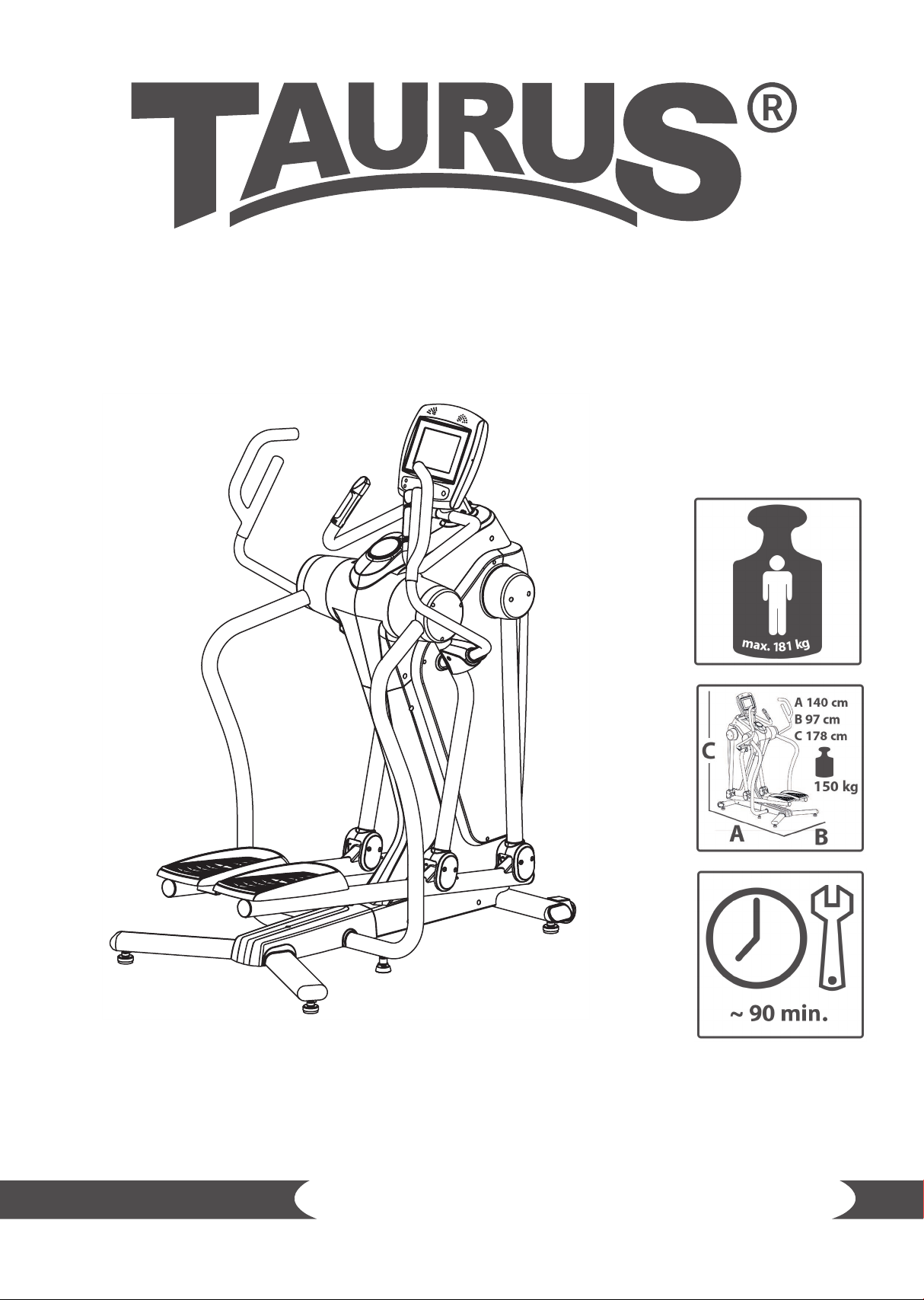
Elliptical cross trainer FS10.5 Pro
ArtNr. TF-FS10.5
TFFS10.5.01.01
Page 2

2
FS10.5 Pro
Page 3

Dear Customer,
Thank you for deciding for a high-quality training equipment of the brand Taurus, the brand that
makes athlete‘s hearts beat faster. Taurus oers a wide range of home tness equipment like elliptical
cross trainers, ergometers, treadmills and rowing machines. Taurus equipment is the optimal
equipment for all those who want to train at home independent of goals and tness level. For further
information please visit www.sport-tiedje.com or www.taurus-tness.de.
SAFETY NOTICE
Please read all of the instructions carefully before assembly and rst use. These
instructions are intended to ensure speedy assembly and explain safe usage. Make
sure that all people exercising with the equipment (in particular children and
persons with limited physical, sensory, mental or motor capabilities) are informed
about these instructions and its content in advance. In case of doubt, a responsible
person must supervise the use of the equipment.
This equipment has been manufactured according to the latest safety knowledge. As far as possible,
potential safety hazards which could cause injury have been eliminated. Make sure to follow the
instructions carefully and that all parts are securely in place. If required, read through the instructions
again to correct any mistakes.
Please pay close attention to the safety and maintenance instructions given here. The contract
partner cannot be held liable for damage to health, accidents or damage to the equipment when it
is not used in accordance with these instructions.
The equipment is suitable for home use, semi-professional use (e. g., hospitals, clubs, hotels, schools,
etc.) as well as for commercial or professional use (e. g., commercial gyms).
Retain these instructions in a safe place for future reference, maintenance or when ordering
replacement parts.
3
Page 4

CONTENTS
1 GENERAL INFORMATION 5
1.1 Technical data 5
1.2 Personal safety 6
1.3 Set-up place 6
2 ASSEMBLY INSTRUCTIONS, MAINTENANCE AND CARE 8
2.1 General instructions 8
2.2 Faults and troubleshooting 9
2.3 Maintenance and service calendar 9
3 ASSEMBLY 10
3.1 Package contents 10
3.2 Assembly instructions 12
4 OPERATING INSTRUCTIONS 23
4.1 Console display 23
4.2 Button functions 25
4.3 Turning on and setting the equipment 26
4.4 Programs 26
4.4.1 Quick Start 26
4.4.2 Proles 27
4.4.2.1 Basic proles 27
4.4.2.2 Advanced proles 29
4.4.3 Heart rate controll 31
4.5 Heart rate measuring 34
5 WARRANTY INFORMATION 36
6 DISPOSAL 38
7 ORDERING ACCESSORIES 38
8 ORDERING SPARE PARTS 39
8.1 Service hotline 39
8.2 Serial number and model name 39
8.3 Parts list 40
8.4 Exploded drawing 43
4
FS10.5 Pro
Page 5

1 GENERAL INFORMATION
1.1 Technical data
TFT display of
+ speed in km/h
+ training time in min
+ training distance in km
+ cadence (rotations per minute)
+ calories burnt in kcal
+ heart rate (when using the hand sensors or a chest strap)
+ Watt
Resistance system: electronic magnetic induction brake system/ generator brake
Resistance levels: 20
Watt: 40 - 300 Watt
Total number of training programs: 18
Heart-rate controlled programs: 6
Basic programs: 6
Advanced programs: 6
Balance mass: 10 kg
Transmission ratio: 1:12
Power:: Generator
Stride length: 11 - 91.4 cm
Weight and dimensions:
Article weight (gross, including packaging): 168 kg
Article weight (net, without packaging): 150 kg
Packaging dimensions (L x W x H): approximately 84 cm x 76 cm x 148 cm
Set up dimensions (L x W x H): approximately 140 cm x 97 cm x 178 cm
Maximum user weight: 181 kg/399 lbs
5
Page 6

1.2 Personal safety
+ Before you start using the equipment, you should consult your physician that this type of
exercise is suitable for you from a health perspective. Particularly aected are persons who: have
a hereditary disposition to high blood pressure or heart disease, are over the age of 45, smoke,
have high cholesterol values, are overweight and/or have not exercised regularly in the past year.
+ Please note that working out excessively can seriously damage your health. Please also be aware
that heart rate monitoring systems might be imprecise.
+ The equipment may only be used for its intended purpose; that means for whole body workouts
for adults.
+ Any other usage is prohibited and potentially dangerous. The contract partner cannot be held
liable for damage resulting from improper use.
+ The equipment is strictly for use by one person at a time.
+ Children should not be allowed unsupervised access to the equipment.
+ Before starting your training, make yourself familiar with all of the equipment‘s functions and
setting options. Have an expert explain the correct usage of the product to you.
+ Make sure that nobody is in the range of motion of the equipment while exercising.
+ Keep your hands, feet and other body parts, hair, clothing, jewelry and other objects well clear of
moving parts.
+ During use, wear suitable sports clothing rather than loose or baggy clothing. When selecting
sports shoes, think about the suitability of the sole – preferably this should be made of rubber or
other non-slip materials. Shoes with heels, leather soles, studs or spikes are not suitable. Never
work out in bare feet.
+ At the rst signs of weakness, nausea, dizziness, pain, diculty in breathing or other abnormal
symptoms, stop your workout immediately and, if necessary, consult your physician.
+ Without prior agreement from your authorized contract partner, opening the equipment is
prohibited.
6
FS10.5 Pro
Page 7

1.3 Set-up place
+ The equipment should only be used indoors, in a suciently heated and dry area (ambient
temperature between 10°C and 35°C). The equipment should not be used outdoors or in rooms
with high humidity (over 70%) like swimming pools. The equipment should only be stored in
surroundings with an ambient temperature between 5°C and 45°C.
+ The training room should be well ventilated during training and not be exposed to any draughts.
+ Choose a location in which to place the equipment such that there is enough free space/
clearance to the front, the rear and to the sides of the equipment (at least 1.50 m). Furthermore,
the equipment should not be set up in main entrances or on escape routes.
+ Always keep the power cable away from hot surfaces and grounds and make sure that the cable
is not stuck somewhere or becomes a „trip hazard“.
+ No objects of any type should be inserted into the openings of the equipment.
+ The equipment should be placed on a level and solid surface, any unevenness in the oor should
be leveled out.
+ A oor protective mat / equipment underlay can help to protect high-quality oor coverings
(parquet, laminate, cork, carpets) from dents and sweat and can help to level out slight
unevenness.
2
7
Page 8

2 ASSEMBLY INSTRUCTIONS, MAINTENANCE AND CARE
2.1 General instructions
+ Please check if all parts and tools belonging to the equipment are included in the delivery and if
there is any transport damage. If there are any complaints, please contact your contract partner
directly.
+ Some of the nuts and bolts to be used in assembly are already pre-mounted in order to make set-
up as easy as possible.
+ The equipment must be assembled by adults. In case of doubt, ask for assistance from another
person with technical skills.
+ Keep children away from the equipment during assembly, because small parts are included in the
delivery and may be swallowed.
+ Make sure that you have enough space (at least 1.50 m) in every direction during assembly.
+ Do not leave any tools and packaging materials like plastic sheeting laying around to avoid danger
of suocation for children.
+ Assemble the equipment on an underlay mat or on the cardboard packaging in order to avoid
damage to the equipment and to the oor (scratches).
+ Before starting assembly, all individual parts should be placed on the oor next to each other.
+ Read the assembly instructions carefully and assemble the equipment according to the illustrations.
Proceed carefully and cautiously.
+ First loosen all parts and check for their correct tting. Then tighten the screws using a tool.
+ Modications to the design or improper repairs may pose a hazard to the user and should not be
carried out. The product warranty may be void as a result.
+ Only authorized service technicians are permitted to carry out all servicing and/or repairs – it
excludes maintenance and care.
+ Damaged or worn components may impair your safety and the lifespan of the equipment. You
should therefore immediately replace damaged or worn components. Please contact your contract
partner in such a case. The equipment should no longer be used until it has been repaired. When
needed, only use original Taurus spare parts.
+ Check the tightness of all screw connections once a month.
+ In order to be able to guarantee the constructively dened safety level of this equipment, we
recommend having the equipment regularly maintained (at least once a year) by specialists
(service technicians of your contract partner).
+ The equipment may be cleaned of dust, dirt and sweat using a damp cloth. The use of solvents
should be strictly avoided. Also, make sure that no liquids (e. g. sweat) get into the openings of the
equipment (e. g. console).
8
FS10.5 Pro
Page 9

2.2 Faults and troubleshooting
The equipment runs through regular quality controls during production. Nevertheless, errors or
malfunctions on the equipment may occur. Individual parts are often the cause of faults and replacement
is usually sucient. Please use the following overview to see the ve most common errors and how to
repair them. If the equipment still does not work properly, please contact your contract partner.
Problem Cause Solution
Drive discs wobble or
make noises
Display does not work
Footplates are creaking
Creaking noises
No pulse reading
Drive pulley is loose Tighten nuts
No plug connection, power
supply not plugged in
Footplates are loose Tighten up the footplate screws
Screws are loose Check screws are properly tightened
• Sources of interference in
the room
• Using a chest strap:
- Unsuitable chest strap
- Chest strap is incorrectly
positioned
- Batteries are empty oder
discharged
Check all plug connections and see if the
power supply is plugged in
• Eliminate sources of interference (e.
g. mobile phone, loudspeaker, WLAN,
mover- and cleaning robot etc.)
• Use a suitable chest strap (see
recommended accessories)
• Reposition the chest strap and/or
moisten the electrodes
• Change or charge the batteries
2.3 Maintenance and service calendar
The following routine work must be done in the specied time intervals:
Part Weekly Monthly Twice a year Annually
Display console C I
Lubricate the moving parts I
Plastic cover C I
Screws and cable connections
Legends: C = cleaning; I = inspect
I
9
Page 10
3 ASSEMBLY
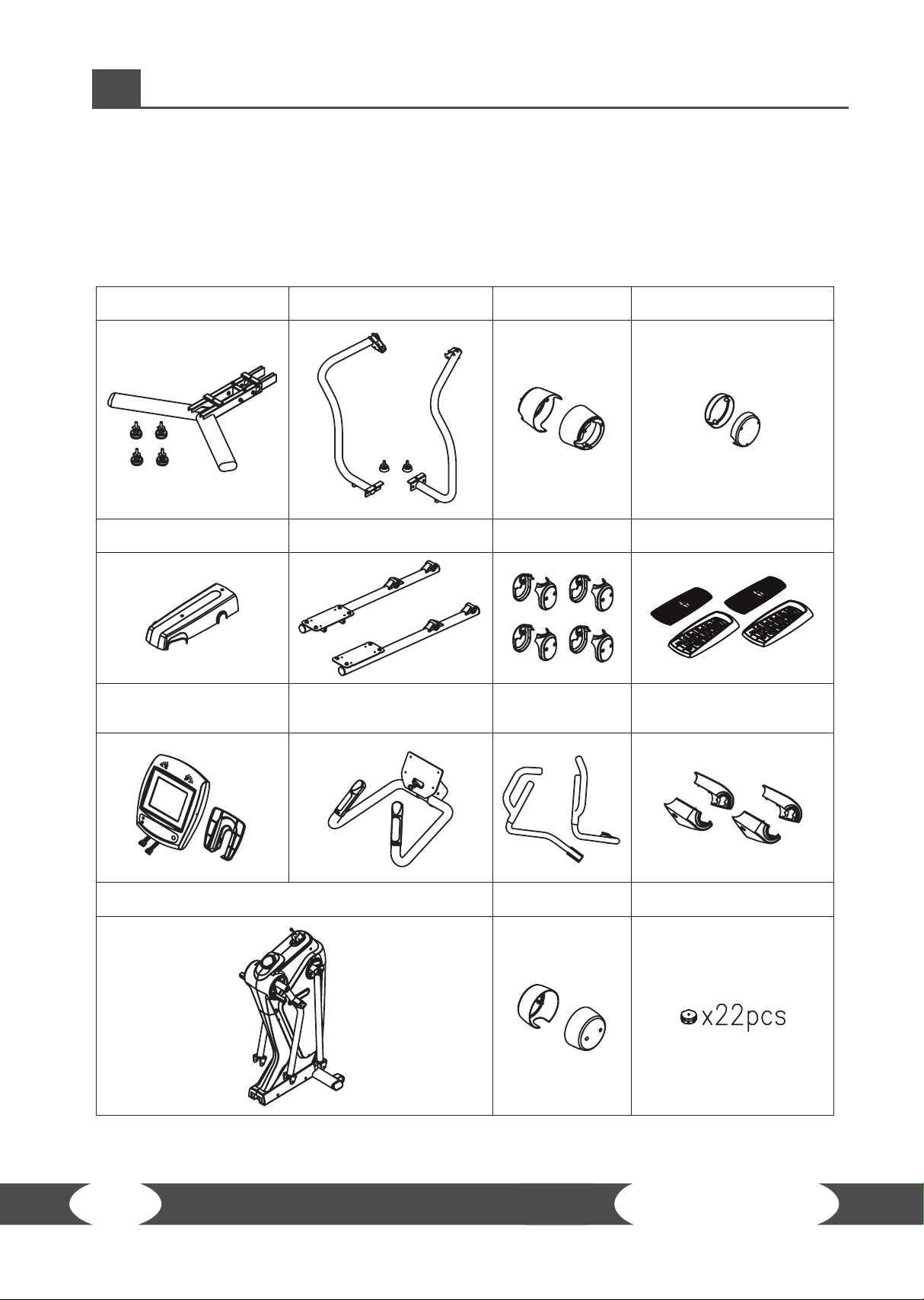
3.1 Package contents
The package contains the parts represented in the illustration, including a power cable with mains
plug. If one of the illustrated parts is missing, please contact your contract partner.
Base Frame (91) &
Leveler (44)
Stationary Handrail (67, 68) &
Basic Leveler (78)
Inner Handrail
Cover (64, 65)
Outer Handrail Cover (63)
Base Cover (90) Pedal Support Arm (86, 87)
Console (100) &
Console Bottom Cover
(102)
Main Frame (28)
Fixed Handlebar (99)
Swing Arm Cover
(80)
Upper Handlebar
(72, 73)
Upper Handlebar
Cover (70)
Pedal (84) & Non-Slip Pad
(83)
Front & Back Upper
Handlebar Cover (162, 163)
Screw Cap (79)
10
FS10.5 Pro
Page 11
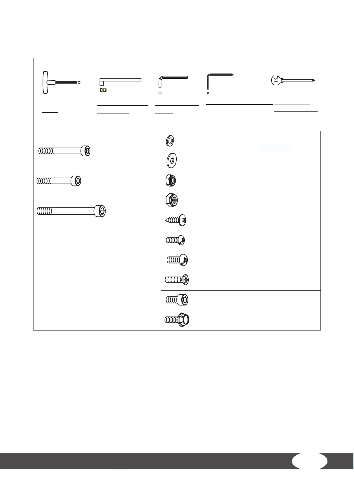
Tools and screw sets
THE FOLLOWING TOOLS ARE INCLUDED FOR ASSEMBLY:
ALLEN WRENCH
(8mm)
138 Bolt, Socket Head (M10xp1.5x65mm) 4pcs
137 Bolt, Socket Head (M8xp1.25x50mm) 4pcs
SOCKET WRENCH
(13 & 17mm)
143 Bolt, Socket Head (M10xp1.5x90mm) 4pcs
ALLEN WRENCH
(8 mm)
110 Lock Washer (M8) 8 pcs
111 Washer (8x16x2.0t) 8pcs
123 Nylon Nut (M8xp1.25) 4pcs
125 Nylon Nut (M10xp1.5) 4pcs
128 Screw, Phillips Truss Head (M4x20mm 6 pcs
132 Screw, Phillips Pan Head (M5xp0.8x15mm) 6 pcs
PHILLIPS SCREWDRIVER
(6mm)
COMBINATION
WRENCH (130mm)
8
133 Screw, Phillips Pan Head (M6xp1.0x15mm) 4 pcs
140 Screw, Phillips Flat Head (M5xp0.8x20mm) 4pcs
136 Bolt, Socket Head (M8xp1.25x15mm) 8 pcs
151 Bolt, Hex Head Flange (M8xp1.25x20mm) 12 pcs
11
Page 12
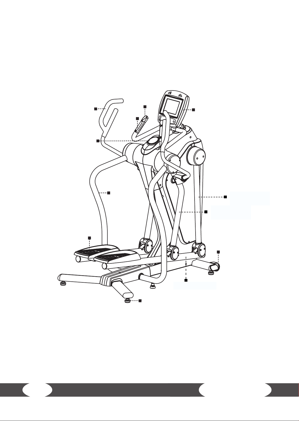
3.2 Assembly instructions
Before starting assembly, look carefully through the individual assembly steps shown and assemble the equipment in the order indicated
Quick
Access Key
Upper Handlebar
Accessory Tray
Pulse
Sensor
Console
Pedal
Stationary
Handrail
Swing arm (front)
Swing arm
(back)
Transportation
Wheel
Pedal support arms
Leveler
12
FS10.5 Pro
Page 13
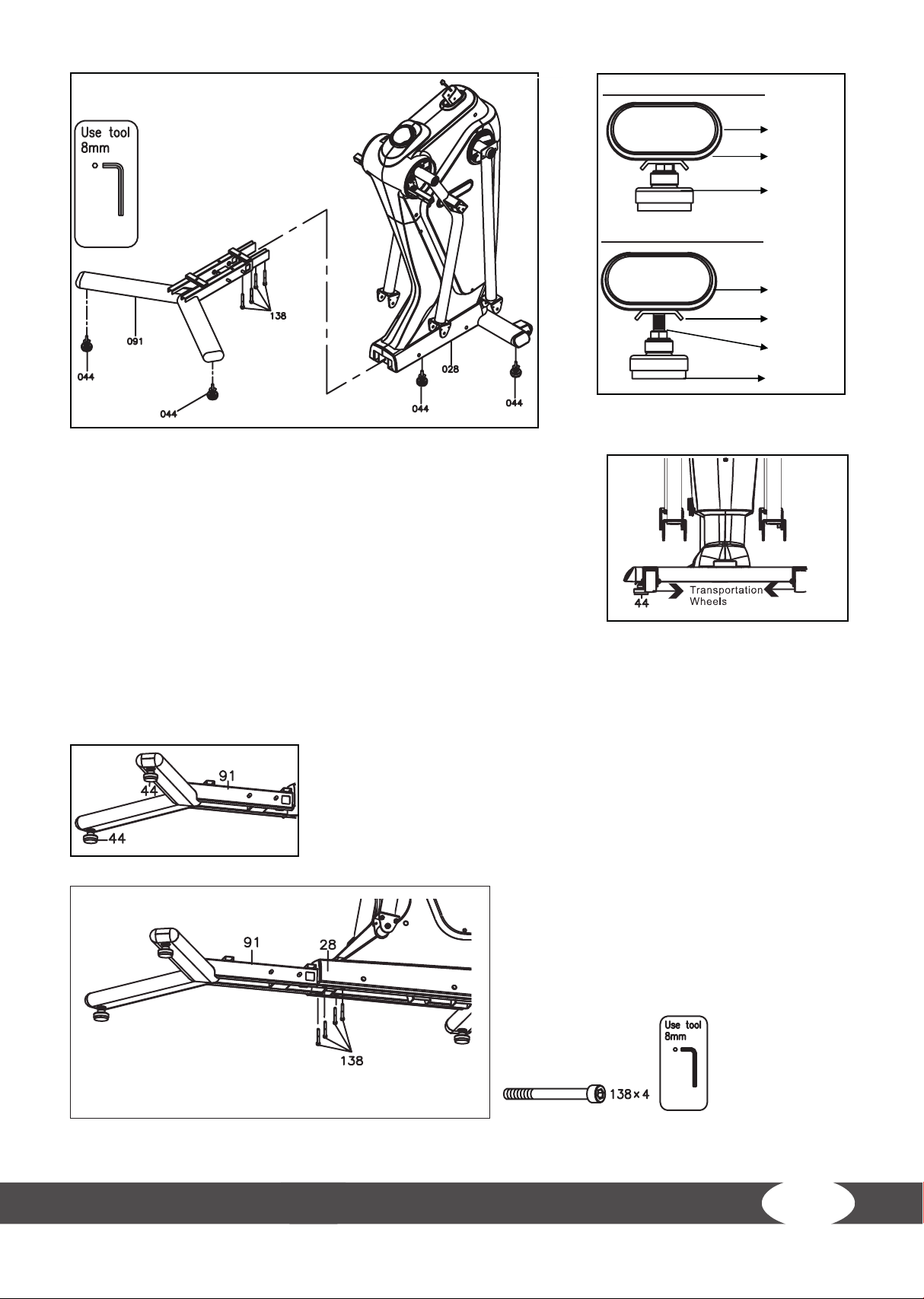
Detailed Lever- drawing 1
Stabilizer
Adjustment
Plate
Leveler (44)
Detailed Lever- drawing 2
Stabilizer
Adjustment
Plate
Screw line
Leveler (44)
Note:
Always ensure that there are two persons available when assembling
the training machine.
Step 1:
a. Attach the two levelers (44) to the main frame‘s (28) front stabilizer
(where the transportation wheels are located).
b. Ensure that the screws‘ threads disappear in the front stabilizer
(detailed lever-drawing 1).
Note:
Please make sure that the elliptical cross trainer stands rmly and safely on the oor. If this is not the case,
loosen the levelers (44) again and adjust them accordingly. It is important that the adjustment plate is
locked underneath the stabilizer (detailed lever-drawing 2).
Step 2:
Attach another pair of levelers (44) underneath the base frame (91).
Step 3:
Fix the base frame (91) to the main frame (28)
with four socket head bolts (138).
13
Page 14
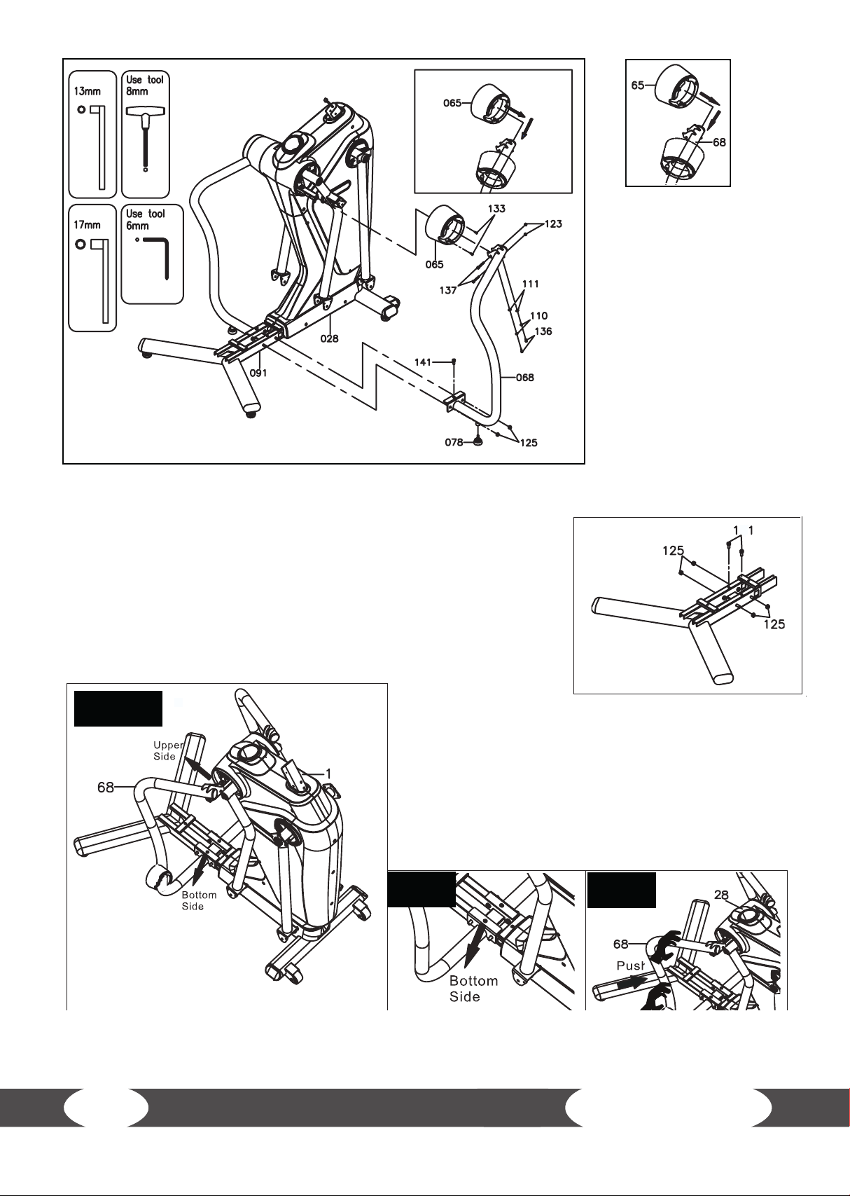
Step 4:
Note:
The inner handrail covers
(64, 65) are marked with an
R (right) and an L (left).
a. Slide the right inner
handrail cover (65) onto
the right stationary
handrail (68).
b. Repeat this step on the
left side.
Step 5:
Remove the two bolts (141) and four nuts (125) from the base frame (91).
Step 6:
a. Place the upper end of the right stationary handrail (68) on the main
frame (28).
b. Place the lower end of the right stationary handrail (68) on the base
frame (91).
Step a., b.
c. Please make sure
that the drill holes of the right stationary handrail (68)
align with the threads of the base frame (91).
d. Now gently push the upper end of the right stationary
handrail (68) towards the main frame (28).
e. Repeat these steps on the left side.
Step c.
4
Step d.
14
FS10.5 Pro
Page 15

Step 7:
Note:
Do not tighten the following screws
and bolts until you are instructed to
do so.
a. Place the two socket head bolts (136),
the two lock washers (110) and the two
washers (111).
b. Place the two bolts (137) and the two
nylon nuts (123).
c. Place one of the previously removed
screws (141) and two nylon nuts (125).
Step a.
Step b.
Step c.
Step 8:
a. Now tighten all the bolts and screws
according to the following order: a, b and c.
b. Repeat these steps on the left side.
Step b.
125 x 2
Step a.
Step c.
15
Page 16

Detailed Lever- drawing 1
Stationary
Handrail
Step 9:
Adjustment
Plate
Leveler (78)
Detailed Lever- drawing 2
Stationary
Handrail
Adjustment
Plate
Screw line
Leveler (78)
a. Attach the two levelers (78) underneath the stationary
handrails (67, 68).
Note:
In case the levelers are not even, please refer to step 1. For
further assistance, please refer to the two detailed leverdrawings on this page.
Step 10:
a. Slide the right inner handrail cover (65) up to the right back swing arm (82).
Note:
The cover has a little recess. Make
sure that that both the stationary
handrail (68) and the right back
swing arm (82) are covered.
Attach the cover with two screws
(133).
b. Attach the outer handrail cover
(63) with three screws (128).
c. Repeat these steps on the left
side.
16
FS10.5 Pro
Page 17

Step 11:
Note:
The four screws (132) on the
front swing arms (76, 77) are
pre-assembled.
a. Remove the four screws
(132).
b. Attach the upper handlebar
covers (70) with the previously
removed screws (132).
Step 12:
Note:
The screws (139) on
the base frame (91) are
pre-assembled.
a. Remove the two
screws (139).
b. Fix the base cover
(90) to the base
frame (91) with the
previously removed screws (139).
c. Now attach the two screw caps (79).
17
Page 18

Step 13:
Note:
The pedal support arms (86, 87) are
marked with an R (right) and and L (left).
a. Fix the right pedal support arm (86) to
the right front and back swing arm (77,
82) with two bolts (143) and two nylon
nuts (125)
b. Repeat this step on the left side.
Step 14:
Note:
The screws (132) on the right front
and back swing arm (77, 82) are preassembled.
a. Remove the eight screws (132).
b. Fix the swing arm covers (80) to the
right front and back swing arm (77, 82)
with the previously removed screws
(132).
c. Now attach the eight screw caps (79).
d. Repeat these steps on the left side.
18
FS10.5 Pro
Page 19
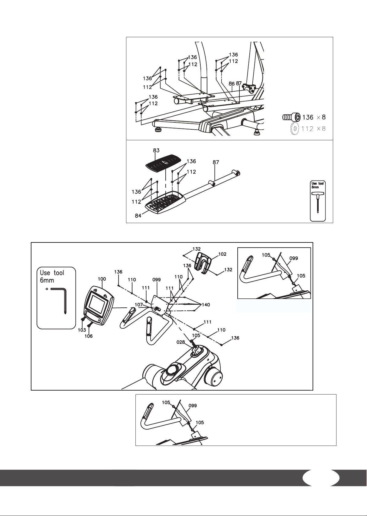
Step 15:
Note:
The bolts (136) and washers
(112) on the pedal support
arms (86, 87) are preassembled.
a. Remove the eight bolts
(136) and washers (112).
b. Fix the right pedal (84) to
the right pedal support arm
(87) with four of the eight
previously removed bolts
(136) and washers (112).
c. Now attach one non-slip
pad (83) on the right pedal
(84).
d. Repeat these steps on the
left side.
Step 16:
a. Gently guide the rear
connection wire (105)
through the xed handlebar
(99).
19
Page 20
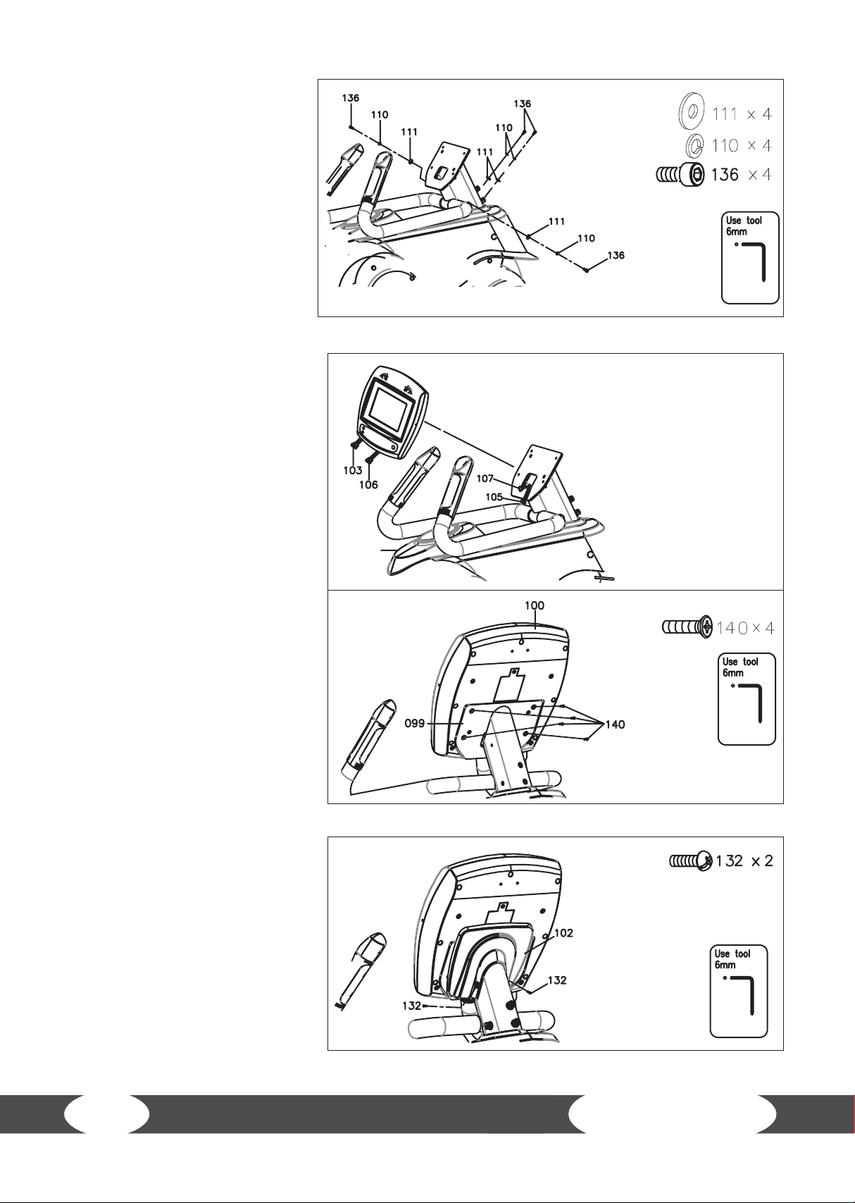
b. Fix the xed handlebar (99)
to the main frame (28) with four
bolts (136), four lock washers
(110) and four washers (111).
Step 17:
a. Connect the upper
connection wire (103) and the
rear connection wire (105) to
one another.
b. Connect the upper pulse
sensor wire (106) and the rear
pulse sensor (107) with one
another.
Note:
Be careful not to pinch the wires
in the following step.
c. Now x the console (100) to
the xed handlebar (99) with
four screws (140)
Step 18:
Fix the console buttom cover
(102) to the console (100) with
two screws (132).
20
FS10.5 Pro
Page 21

Note:
The screws (132) on the back swing arms (81, 82) are pre-assembled.
a. Remove the four screws (132).
Note:
The upper handlebars (72, 73) are marked with an R (right) and an L (left).
b. Fix the right upper handlebar
(73) to the right back swing arm
(82) with six bolts (151).
Step 19:
L
1
c. Attach the front and back upper
handlebar cover (162, 163) with
two of the four previously removed
screws (132).
d. Repeat these steps on the left
side.
Note:
Please ensure that all screw
connections are tight before you
use the elliptical cross trainer.
21
Page 22

I
Angle adjustment of the console
Adjust the angle of the console by pressing lightly on the upper or
lower end of the console.
Transporting the equipment
Lift the equipment on the rear base foot and move the equipment to the desired space.
22
FS10.5 Pro
Page 23

4 OPERATING INSTRUCTIONS
4.1 Console display
23
Page 24

Wear a chest strap or grab the hand pulse sensors with both hands. The
heart symbol will appear a few seconds later and your heart rate will
Pulse
Watt Indicates Watt in the range from 0 - 999 Watts.
Level Indicates the resistance level between 1 - 16.
Speed Indicates the speed between 0.0 - 99.9 km/h.
be displayed. If you do not grab the hand pulse sensors correctly with
your hands and it does not receive a heart rate, the HR display will turn
o after a few seconds. As soon as your hands grab the sensors again
correctly, the heart rate will be displayed again.
Time
Distance Indicates the distance covered between 0.0 - 99.9 km.
RPM Indicates the rotations per minute between 0 - 255.
Calories Indicates the calories burnt between 0 – 9999.
METS
Ascending: If no target value is set, the time will run ascending from
0:00 to 99:59 minutes.
Denition: MET or metabolic equivalent is used to measure the average
metabolic rate for a person. MET describes the quantity of oxygen that an
average person needs when in rest.
1 MET = 3.5 ml/kg/min (The body consumes 3.5 milliliters of oxygen per
kilogram per minute) is the amount of oxygen that the body needs when
in rest.
The more intensively the body works, the more oxygen is consumed and
the higher the MET level. If you train at a level of seven METS, then you are
working approximately 7 times harder than when in rest. Furthermore,
you need 7 times as much oxygen than when in rest.
+ Training between three to six METs is seen as moderate physical activity.
+ Training at more than six METs is seen as strong physical activity.
Media
24
+ Loudspeaker
+ MP3/CD player connection
+ Earphones connection
+ Mute button
FS10.5 Pro
Page 25

4.2 Button functions
START Press START to start the training.
PAUSE Press PAUSE to pause the training.
STOP Press STOP to end the training. All values are reset to zero.
UP Press UP to increase resistance during training.
DOWN Press DOWN to lower the resistance during training.
BACK Press BACK to return to the previous screen.
STATISTICS Press STATISTICS to display your training values.
Press H.R. Trend to display your heart rate diagram.
If the console receives your heart rate, it will be recorded automatically every 60
H.R. Trend
seconds.
Note: Make sure that you wear a chest strap or hold the pulse sensors with both
hands so that the console can receive your heart rate.
Press H.R. Trend again to return to the training program.
25
Page 26

4.3 Turning on and setting the equipment
Turn on: The console turns on automatically if you pedal with more than 25 RPM.
Turn o: The console will turn o automatically after 60 seconds of inactivity.
Note: The console contains rechargeable batteries. The console turns o if the batteries are empty.
The batteries are charged with rotations of more than 35 RPM.
4.4 Programs
You have three options on the start screen:
1. Quick Start. Select Quick Start if you would like
to start directly in the manual program without
settings.
2. Prole: Here you can choose between Basic
proles and Advanced proles.
3. Heart rate controlled training (H.R.C.) (60%, 65%,
70%, 75%, 80%, 85%)
Start screen
4.4.1 Quick Start
Press Quick Start on the start screen.
Once you have selected Quick Start, you will see the following displays (count-down) one after the
other.
Training screen
26
FS10.5 Pro
Page 27

4.4.2 Proles
Press Prole on the start screen.
Then select between Basic and Advanced.
Basic Prole: You can choose between six basic
programs.
Advanced Prole: You can choose between six
advanced programs.
4.4.2.1 Basic proles
Select Basic Prole.
Now you can select from the following six
programs:
Manual, Fitness, Random, Rolling, Fat Burn, Ascent.
Press Back to return to the previous screen.
Press Next to continue with the weight setting.
Press Quick Start to immediately begin the
training.
Now you can set your weight between 30 - 181 kg
(66 - 399 lbs).
Press Back to return to the previous screen.
Press Next to continue with the time setting.
Press Quick Start to immediately begin the
training.
27
Page 28

Now you can set your desired training time
between 5:00 - 99:00 minutes.
Press Back to return to the previous screen.
Press Next to start training.
Press Quick Start to immediately begin the
training.
H.R. Trend
Press H.R. Trend to display your heart rate
diagram.
If the console receives your heart rate, it will be
recorded automatically every 60 seconds.
Note: Make sure that you wear a chest strap or
hold the pulse sensors with both hands so that the
console can receive your heart rate.
Press H.R. Trend again to return to the training
program.
Press STATISTICS to display your training values.
Note: You can press this button at any time while
training in order to display the statistics. Press the
Back button to return to the training screen.
28
FS10.5 Pro
Page 29

4.4.2.2 Advanced proles
Select Advanced Prole.
Now you can select from the following six
programs:
Constant Power, Iron Man, Mountain, Weight
Loss, Interval, Valley.
Before you select the Constant Power program,
you should get to know the dierence between
constant power and constant resistance.
Constant resistance (in
most training programs)
Watt control
(constant wattage) (in the
Constant Power program)
Now you can set your weight between 30 - 181
kg (66 - 399 lbs).
Press Back to return to the previous screen.
Press Next to continue with the time setting.
Press Quick Start to immediately begin the
training.
Resistance remains the same independent of the speed.
Resistance depends on the speed. The console examines the cadence
(RPM) of the user in order to guarantee a constant wattage during
training.
If the speed increases, the resistance decreases.
If the speed decreases, the resistance increases.
29
Page 30

Now you can set your desired training time
between 5:00 - 99:00 minutes.
Press Back to return to the previous screen.
Press Next to start training.
Press Quick Start to immediately begin the
training.
H.R. Trend
Press H.R. Trend to display your heart rate
diagram.
If the console receives your heart rate, it will be
recorded automatically every 60 seconds.
Note: Make sure that you wear a chest strap or
hold the pulse sensors with both hands so that the
console can receive your heart rate.
Press H.R. Trend again to return to the training
program.
Press STATISTICS to display your training values.
Note: You can press this button at any time while
training in order to display the statistics. Press the
Back button to return to the training screen.
30
FS10.5 Pro
Page 31

4.4.3 Heart rate control
Select “Heart Rate Control” on the start screen.
Now you can set your weight between 30 - 181 kg
(66 - 399 lbs).
Press Back to return to the previous screen.
Press Next to continue with the time setting.
Press Quick Start to immediately begin the
training.
Now you can set your desired training time
between 5:00 - 99:00 minutes.
Press Back to return to the previous screen.
Press Next to start training.
Press Quick Start to immediately begin the
training.
31
Page 32

Now you can set your age between 5 - 99 years.
Press Back to return to the previous screen.
Press Next to continue with the gender setting.
Press Quick Start to immediately begin the
training.
Now you can select your gender.
Press Back to return to the previous screen.
Press Next to continue with the target heart rate
setting.
Press Quick Start to immediately begin the
training.
Now you can select your target heart rate (60%,
65%, 70%, 75%, 80%, 85% of the maximum heart
rate)
Press Back to return to the previous screen.
Press Next to start training.
Press Quick Start to immediately begin the
training.
32
FS10.5 Pro
Page 33

H.R. Trend
Press H.R. Trend to display your heart rate
diagram.
If the console receives your heart rate, it will be
recorded automatically every 60 seconds.
Note: Make sure that you wear a chest strap or
hold the pulse sensors with both hands so that
the console can receive your heart rate.
Press H.R. Trend again to return to the training
program.
Press STATISTICS to display your training values.
Note: You can press this button at any time while
training in order to display the statistics. Press the
Back button to return to the training screen.
33
Page 34

4.5 Heart rate measuring
Pulse measuring through hand sensors
The hand sensors integrated in the handles allow you to determine your heart rate. You can measure
your heart rate by lightly grasping the sensors with both hands at the same time. Blood pressure
changes occur due to the heartbeat. The sensors measure the changes to the electric skin resistance
caused by it. These values are then used to create an average and are displayed on the screen of the
console as a heart rate.
Note:
For some people, the skin resistance change caused by the heart rate is so minimal that the
measurements do not allow for usable values. Strong callus or sweat on the hands may also impair a
correct measurement. In such cases, the heart rate will not be shown at all or only incorrectly.
If the measurement is incorrect or not taken at all, please check if it happens to only one person or to
several people. If the pulse display only does not work in a single case, the equipment is not defective.
In this case, we recommend using a chest strap to achieve a permanently correct heart rate display.
CAUTION: Your training equipment is not a medical device. Dierent factors may inuence the
accuracy of the heart rate display. The heart rate display only serves as a training aid.
Telemetric heart rate measuring
This elliptical cross trainer is already equipped with a heart rate receiver as standard. Using a chest
strap makes it possible for you to have a wireless heart rate measuring. This optimal and ECG-precise
type of measuring reads the heart rate directly from the skin through a transmitting chest strap. The
chest strap then sends the impulse to the receiver integrated in the console.
Positioning the chest strap and moistening the electrodes:
Place the belt directly below the chest, while the transmitter should be placed on the middle of the
chest. The chest strap should sit comfortably, but not too loose. If the belt is too loose, the contact
to the electrodes may be disrupted or the belt may slip while exercising. The transmitter turns on
automatically once it is put on. In order to allow for a precise measuring, you should moisten the
rubber electrodes. This is best done with a special chest strap contact gel, which is also used for
ultrasound scans.
Note:
If you have not been active in doing sports for a longer period of time, you should rst go to your
physician in order to discuss your training with them. You should also contact your physician in
advance in the event of heart problems, high/low blood pressure and obesity.
Training with heart rate orientation
Heart rate orientation guarantees an extremely eective and healthy training. Through your age
and the following table, you can quickly and easily read and determine the optimal pulse for your
training. An alarm will sound if your heart rate exceeds the set target heart rate. Which target heart
rate is important for which training goal can be found out in the following.
34
FS10.5 Pro
Page 35

Fat burning (weight management): The main goal here is to burn deposits of fat. In order to
20
80
100
120
140
160
180
200
220
65 7060555045403525 30
200
195
190
185
180
175
170
180
150
110
146
107
175
171
166
162
157
153
148
143
139
135
131
128
124
105
102
99
96
94
91
88
85
83
113
116
120
144
139
136
150
155
160
165
Herzfrequenz-Diagramm zur Belastungsintensität
Maximalpuls (220-Alter)
90% vom Maximalpuls - Anaerobes (maximales) Belastungstraining
75 % vom Maximalpuls - Herz-Kreislauf-Training (Ausdauertraining)
55% vom Maximalpuls - Fettverbrennung (Gewichtsregulierung)
Herzfrequenzschläge
Alter
achieve this training goal, a low training intensity (approximately 55% of the maximum heart rate)
and a longer training period are required.
Cardiovascular training (cardio training): The primary goal is to increase stamina and tness
through an improved provision of oxygen through the cardiovascular system. In order to achieve
this training goal, medium intensity (approximately 75% of the maximum heart rate) with a medium
training period is required.
Anaerobic (maximum) load training: The main goal of maximum load training is to improve
recovery after short, intense loads in order to be able to quickly return to the aerobic zone. In order
to achieve this training goal, a high intensity (approximately 90% of the maximum heart rate) with
short, intense load is required, which is followed by a recovery phase in order to prevent muscle
fatigue.
Example:
For a 45-year-old man or woman, the maximum heart rate is 175 (220 - 45 = 175).
• The fat burning target zone (55%) is at approximately 96 beats/min.
= (220 - age) x 0.55.
• The cardio target zone (75%) is at approximately 131 beats/min.
= (220 - age) x 0.75.
• The maximum heart rate for an anaerobic load training (90%) is at approximately 157 beats/
min. = (220 - age) x 0.9.
35
Page 36

5 WARRANTY INFORMATION
Taurus training tness equipment is subject to strict quality controls. However, if a tness equipment
purchased from us does not work perfectly, we take it very seriously and ask you to contact our
customer service as indicated. We are happy to help you by phone via our service hotline.
Error descriptions
Your tness equipment is developed for long-term, high-quality training. However, should a problem
arise, please rst read the operating instructions. For further assistance, please contact your contract
partner or call our service hotline. To ensure your problem is solved as quickly as possible, please
describe the defect as exactly as possible.
In addition to the statutory warranty, we provide a warranty for every tness equipment purchased
from us according to the following provisions.
Your statutory rights are not aected.
Warrantee
The warrantee is the rst/original buyer and/or any person who received a newly purchased product
as a gift from the original buyer.
Warranty periods
The following warranty periods begin on delivery of the tness equipment.
Model Use Full warranty Frame
Home use 24 months 30 years
FS10.5 Pro
Repair costs
According to our choice, there will either be a repair, a replacement of individual damaged parts or
a complete replacement. Spare parts, that have to be mounted while assembling the equipment,
have to be replaced by the warrantee personally and are not a part of repair. After the expiration of
the warranty period for repair costs, a pure parts warranty applies, which does not include the repair,
installation and delivery costs.
The terms of use are dened as follows:
• Home use: solely for private use in private households up to 3 hours per day
• Semi-professional use: up to 6 hours per day (e. g. rehabilitation centers, hotels,
clubs, company gyms)
• Professional use: more than 6 hours per day (e. g. commercial gyms)
Semi-professional use 12 months
Professional use 6 months
36
FS10.5 Pro
Page 37

Warranty service
Within the warranty period, equipment which develops faults as a result of material or manufacturing
defects, will be repaired or replaced at our discretion. Ownership of equipment or parts of equipment
which have been replaced is transferred to us. The warranty period is not extended nor does a new
warranty period begin following repair or replacement under the warranty.
Warranty conditions
For the warranty to be valid, the following steps must be taken:
Please contact our customer service by email or phone. If the product under warranty has to be sent
in for repair, the seller bears costs. After expiry of the warranty, the buyer bears the costs of transport
and insurance. If the fault is covered by our warranty, you will receive a new or repaired equipment
in return.
Warranty claims are invalid in case of damage resulting from:
• misuse or improper handling
• environmental inuences (moisture, heat, electrical surge, dust, etc.)
• failure to follow the current safety measures for the equipment
• failure to follow the operating instructions
• use of force (e. g. hitting, kicking, falling)
• interventions which were not carried out by one of our authorized service centers
• unauthorized repair attempts
Proof of purchase and serial number
Please make sure that you are able to provide the appropriate receipt when claiming on your
warranty. So that we can clearly identify the model of your equipment, and for the purposes of our
quality control, you will need to give the serial number of your equipment, when contacting the
service team. Where possible please have your serial number and your customer number ready
when you call our service hotline. It will help us to deal with your request swiftly. If you have trouble
nding the serial number on your tness equipment, our service team is at your disposal to oer
further information.
Service outside the warranty period
We are also happy to issue an individual cost estimate if there is a problem with your tness equipment after the warranty has expired, or in cases which do not fall under the terms of the warranty, e.
g. normal wear and tear. Please contact our customer service team to nd a quick and cost-eective
solution to your problem. In such a case you will be responsible for the delivery costs.
Communication
Many problems can be solved just by speaking to us as your contract partner. We know how important it is to you as a user of the tness equipment to have problems solved quickly and simply, so
you can enjoy working out with minimal interruption. For that reason, we also want to resolve your
queries quickly and in a straightforward manner. Thus, please always keep your customer number
and the serial number of the faulty equipment handy.
37
Page 38

6 DISPOSAL
At the end of its operational life, this equipment cannot be disposed of in normal
household waste. Instead, it must be disposed of via an electricals recycling centre.
Further information can be obtained from your local authority‘s recycling service.
The materials can be recycled as per their symbols. Through the reuse, recycling
of materials or other forms of recovery of old equipment, you make an important
contribution to the protection of the environment.
7 ORDERING ACCESSORIES
Floor mat set
Art. No. TF-FMS-B or TF-FMS-W
Transmitter chest strap
Art. No. ST1000
Comfort chest strap Premium
Art. No. ST1050
Chest strap electrode gel 250ml
Art. No. BK-250
38
Fitness equipment care set
Art. No. HF-500
FS10.5 Pro
Page 39

8 ORDERING SPARE PARTS
8.1 Service hotline
So that we can give you the best possible service, please have your model name, part number, serial
number, exploded drawing and parts list ready.
Service hotline
DE
+49 4621 4210-0
+49 4621 4210-699
service@sport-tiedje.de
Mo. - Fr. 8:00 - 18:00
Sa. 9:00 - 18:00
NL
+31 172 619961
info@tshop.nl
Ma. - Do. 9:00 - 17:00
Vr. 9:00 - 21:00
Za. 10:00 - 17:00
DK
80 90 16 50
+49 4621 4210-945
info@t-tness.dk
Ma. - Fr. 8:00 - 18:00
Lø. 9:00 - 18:00
UK
+44 141 876 3972
orders@powerhousetness.co.uk
Mon. - Fri. 9:00 - 17:00
FR
+33 (0) 172 770033
+49 4621 4210-933
service-france@sport-tiedje.fr
Lun. - Ven. 8:00 - 18:00
Sam. 9:00 - 18:00
INT
+49 4621 4210-0
service-int@sport-tiedje.de
Mon - Fri 8:00 - 18:00
Sat 9:00 - 18:00
8.2 Serial number and model name
Before assembling your equipment, nd the serial number on the white sticker and enter it in the appropriate space.
Serial number:
Brand / category: Model name:
Taurus / Crosstrainer TF-FS10.5
39
Page 40

8.3 Parts list
No. Description Qty. No. Description Qty.
1 Bracket for 2-Stage System 2 32 Magnet 1
2 Spacer (8x17x62mm) 4 33 Pulley (190) 2
3 Square Plug (30x60) 2 34 Crank Axle 1
4 Support Tube for Front Cover 1 35 Controller 1
6 Rod End Plain Bearing 4 36 Support Plate 2
7 Linkage for Rod End Bearing 2 37 Stopper (35mm) 2
8 Bearing (6201) 4 38 Sleeve 6
9 Spacer (10x17x44mm) 1 39 Wheel Axle 2
10 Shock-Absorbing Foam 2 40 Transportation Wheels 2
11 Crank for 2-Stage Bracket 1 41 Sensor Wire Stand 1
12 Belt (762J8) 2 42 Decoration Bracket 1
13 Eye Bolt (67mm) 6 43 EndCap 2
14 Tension Bracket 8 44 Leveler (50mm) 4
16 Bearing (6000) 4 45 Resistor 1
17 Spacer (10x14x32mm) 3 46 Eye Bolt (40mm) 2
18 Pulley (120-42mm) 2 47 Generator 1
19 Belt (660J8) 1 48 Belt (1355J8) 1
20 Bearing (6300) 2 49 Linkage Wheel Bearing Adapter 4
21 Flywheel Hub 1 50 Wheel Bearing Spacer (8x14x18mm) 2
22 Flywheel 1 51 Crank Linkage 2
23 Spacer (8x14x32mm) 2 53 Bearing (6905) 16
24 Magnetic Shield Plate 2 54 Swing Linkage 2
25 Plate Spacer (6x16x20mm) 2 55 Front Cover 1
26 Magnetic Bracket 2 56 Upper-Left Decoration Cover 1
27 Magnet (N38) 8 57 Upper-Right Decoration Cover 1
28 Main Frame 1 58 Accessory Tray 1
29 Crank 2 59 Rear Left-Side Cover 1
30 Bearing (6005) 2 60 Rear Right-Side Cover 1
31 Spacer (25.1x32x40mm) 1 61 Main Left-Side Cover 1
30 Transportation Wheels 2 62 Main Right-Side Cover 1
31 EndCap 4 62 Back Aluminum Upright Cover 1
40
FS10.5 Pro
Page 41

No. Description Qty. No. Description Qty.
63 Outer Stationary Handrail Cover 2 95 Pulse Sensor Bottom Housing 2
64 Left Inner Stationary Handrail Cover 1 96 Left Quick-Access Key 1
65 Right Inner Stationary Handrail Cover 1 97 Right Quick-Access Key 1
66 Round Plug (50mm) 2 98 Foam Grip for Fixed Handlebar 2
67 Left Stationary Handrail 1 99 Fixed Handlebar 1
68 Right Stationary Handrail 1 100 Console 1
70 Upper Handlebar Cover 2 101 Battery Door 1
72 Left Upper Handlebar 1 102 Console Bottom Cover 1
73 Right Upper Handlebar 1 103 Upper Connection Wire 1
76 Left Front Swing Arm 1 105 Rear Connection Wire 1
77 Right Front Swing Arm 1 106 Upper Pulse Sensor Wire 1
78 Basic Leveler (50mm) 2 107 Rear Pulse Sensor Wire 1
79 Screw Cap 22 108 Sensor Wire 1
80 Inner Bottom Swing Arm Cover 8 109 Generator Wire 2
81 Left Back Swing Arm 1 110 Lock Washer (M8) 28
82 Right Back Swing Arm 1 111 Washer (8×16×2.0t) 11
83 Non-Slip Pad 2 112 Washer (8×23×2.0t) 12
84 Pedal 2 113 Washer (8×30×2.0t) 8
85 Square Plug (20x40) 4 114 Washer (10×23×2.0t) 9
86 Left Pedal Support Arm 1 115 Nut (M25×p1.25) 2
87 Right Pedal Support Arm 1 116 Flange Nut (M10×p1.25) 1
88 Bearing (6002) 2 117 Nut (M10×p1.25) 1
89 Wheel Bearing Spacer (10x25x47mm) 4 118 Lock Washer (M6) 2
90 Base Cover 1 119 Tube Connector Nut 30×30(M6) 2
91 Base Frame 1 120 Nut (M10xp1.5) 2
92 Left Membrane Key 1 121 Nut (M16xp2.0) 4
93 Right Membrane Key 1 122 Nylon Nut (M6×p1.0) 10
94 Pulse Sensor Top Housing 2 123 Nylon Nut (M8×p1.25) 16
92 Washer (8×38×2.0t) 4 124 Thin Nylon Nut (M8×p1.25) 4
93 Washer (10×23×2.0t) 2 2 125 Nylon Nut (M10×p1.5) 22
94 Washer (21×30×1.0t) 3 4 125 Nylon Nut (M10×p1.5) 2
41
Page 42

No. Description Qty. No. Description Qty.
126 Bolt ( M5xp0.8x10mm) 1 148 Bolt (M8×p1.25×60mm) 2
127 Screw (M3×10mm) 5 149 Bolt (M10×p1.5×85mm) 11
128 Screw (M4×20mm) 18 150 Bolt (M8×p1.25×20mm) 4
129 Screw (M5×20mm) 34 151 Bolt (M8×p1.25×20mm) 12
130 Screw (M3×p0.5×20mm) 2 152 Bolt (M8×p1.25×16mm) 2
131 Screw (M3×p0.5×25mm) 4 153 Washer (26×34×1.0t) 8
132 Screw (M5×p0.8×15mm) 28
133 Screw (M6×p1.0×15mm) 4 155 Wing Nut 2
134 Bolt (M6×p1.0×15mm) 6 156 Round Plug (60mm) 4
135 Bolt (M6×p1.0×30mm) 2 157 Bolt (M8×p1.25×40mm) 2
136 Bolt (M8×p1.25×15mm) 34
137 Bolt (M8×p1.25×50mm) 6
138 Bolt (M8×p1.5×65mm) 4 160 Lock Washer (M10) 3
139 Screw (M5×p0.8×30mm) 2 161 Pedal Wheel Bearing Adapter 8
140 Screw (M5xp0.8x20mm) 4 162 Front Upper Handlebar Cover 2
141 Bolt (M10×p1.5×20mm) 2 163 Back Upper Handlebar Cover 2
142 Bolt (M10×p1.5×70mm) 2 164 Bearing (6004) 8
143 Bolt (M10×p1.5×90mm) 4 165 Generator Support Bracket 1
144 Bolt (M8×p1.25×15mm) 4 166 Washer (6x13x1.0t) 2
145 Bolt (M8×p1.25×45mm) 2 167 TFT Battery Connection Wire 1
146 Bolt (M10xp1.5x60mm) 2 168 TFT Battery 1
154 Wheel Bearing Adapter 6
158 EndCap (50x100) 2
159 Support Plate for 2-Stage System
2
147 Bolt (M8×p1.25×55mm) 2 169 TFT Battery Bracket 2
42
FS10.5 Pro
Page 43

8.4 Exploded drawing
43
Page 44

44
FS10.5 Pro
Page 45

45
Page 46

CONTACT
Company head oce
Sport-Tiedje GmbH
Flensburger Str. 55
24837 Schleswig
Germany
Hotline for Technical Information
DE
+49 4621 4210-0
+49 4621 4210-698
technik@sport-tiedje.de
NL
+31 172 619961
info@tshop.nl
DISCLAIMER
DK
80 90 16 50
+49 4621 4210-945
info@t-tness.dk
UK
+44 141 876 3986
support@powerhousetness.co.uk
FR
+33 (0) 172 770033
+49 4621 4210-933
service-france@sport-tiedje.fr
INT
+49 4621 4210-0
service-int@sport-tiedje.de
www.sport-tiedje.com
www.taurus-tness.de
©2011 TAURUS is a registered brand of the company Sport-Tiedje GmbH. All rights
reserved. Any use of this trademark without the explicit written permission of SportTiedje is prohibited.
Product and instructions are subject to change. Technical data can be changed without
advance notice.
Please nd a detailed overview including address and opening hours for all specialist tness stores of the
Sport-Tiedje Group in Germany and abroad on the following website.
www.sport-tiedje.com/en/stores
46
FS10.5 Pro
Page 47

47
Page 48

Elliptical cross trainer FS10.5 Pro
 Loading...