

Page 1
1
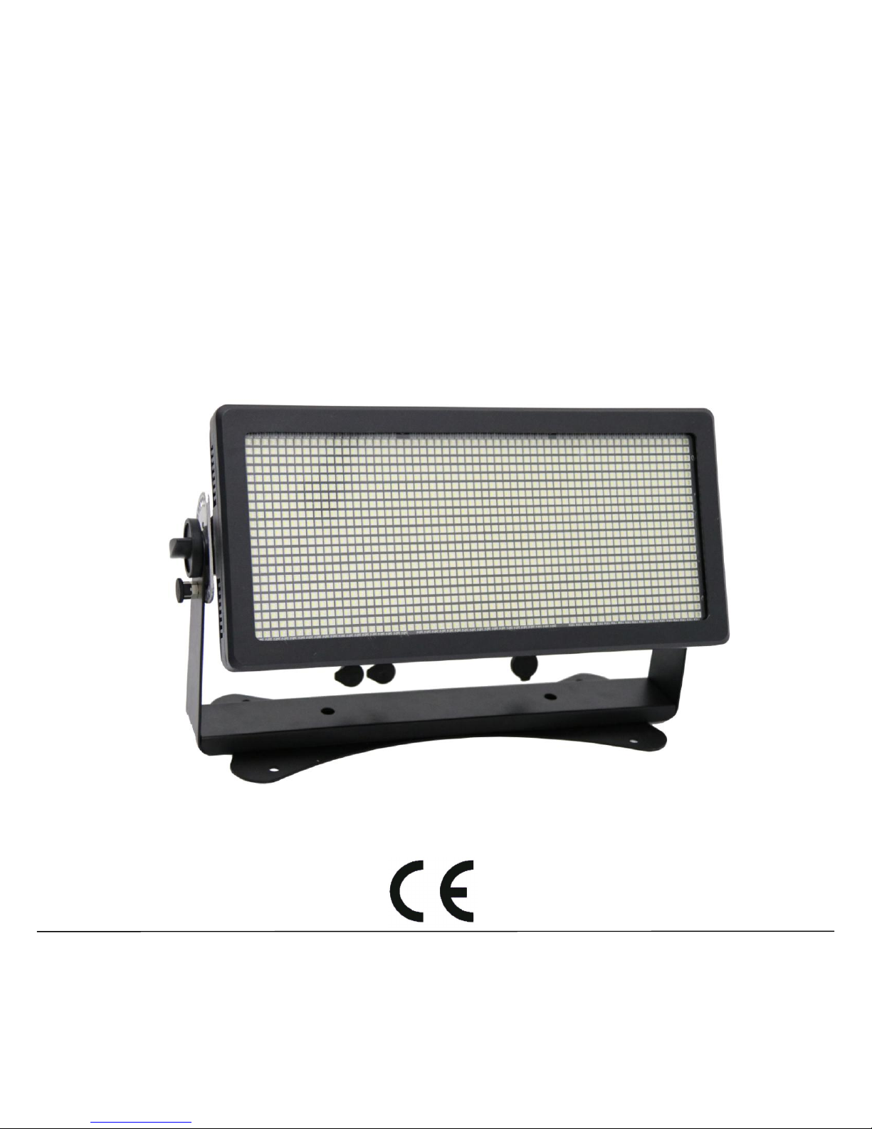
Cyclone 1320
-Strobe,Blinder,Flood and Wash Light
User Manual
Thanks for choosing our goods please read this manual carefully
before your operating and keep this manual for future needs
Page 2

2
Thank you for purchasing Cyclone 1320, Every unit has been thoroughly
tested and has been shipped in perfect operating condition. Carefully
check the shipping carton for damage that may have occurred during
shipping. If the carton appears to be damaged, carefully inspect your
fixture for any damage and be sure all accessories necessary to operate
the unit has arrived intact. In the case damage has been found or parts
are missing, please contact the manufacturer or your dealer for further
instructions. You now own a professional lighting unit that offers endless
possibilities.
For your own safety and that of others, please read this instruction
manual carefully before installing the unit.
Anyone involved in installing, operating or servicing the Super Beam 60
must: • Be a qualified, authorized professional
•Strictly follow the instructions in this user manual.
Please take the time to read this manual carefully and thoroughly before
installing and operating the luminaire. You should have a good
knowledge of its operating conditions and all pertinent product
information.
After you have become familiar with this manual, we recommend that
you keep a copy for future use. All the information found in this manual
Page 3

3
is subject to change without notice. We reserves the right to modify and
upgrade its range of products, with no obligation to integrate these
changes into products already sold.
Warning
● To prevent or reduce the risk of electrical shock or fire ,do not expose
the unit to rain or moisture.
● Do not open the unit within five minutes after switching off.
● Please consider that damages caused by manual modifications to the
device are not subject to warranty.
Installation
The unit should be mounted via its screw holes on the bracket.Always
ensure that the unit is firmly fixed to avoid vibration and slipping while
operating.And make sure that the structure to which you are attaching
the unit is secure and is able to support a weight of 10 times of the
unit’s weight. Also always use a safety cable that can hold 12 times of
the weight of the unit when installing the fixture.
The equipment must be fixed by professionals.And it must be fixed at a
place where is out of the touch of people and has no one pass by or
under it.
Page 4

4
Specifications and Features:
• DMX Channel: 4/6/10/18(RGBW);3/6/9/18(RGB)
• 4 Dimmer Curve
• IP rated: IP65
• LED Source: 1320pcs 5050 SMD RGBW(RGB) LED
• Compact housing with mounting bracket and fixation screw
• Dynamic macro effect
• LCD display for addressing and special functions settings
• Control: DMX,Stand-alone,Master/Slave
• Electronic supply with active PFC
• Strobe:1-30Hz,variable flash rate,intensity and duration
• Can use as blinder, flood light, wash light and strobe Light
• Locking possibility at the brackets with large mental butterfly screws
• Power Input: AC90~240V,50/60HZ
• Power: Max 1200W
• Wide beam angle(120°)
• Product Size: 256x21x32m
• Carton Size: 58x22x34mm
• Net Weight: 10.5 KG
• Gross Weight: 12KG
Page 5
5
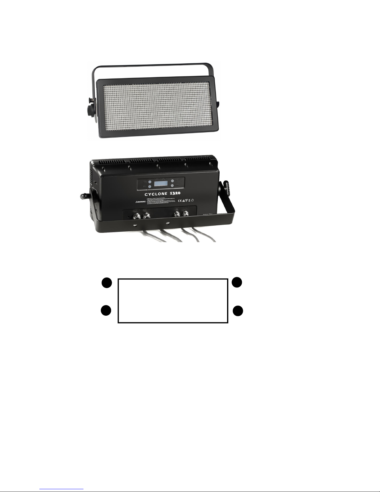
Product View
Menu Operation
Menu UP
Enter DOWN
• Menu : Main menu, choose the function
• Enter: Enter into the function and confirm
• UP: Choose the UP data
• DOWN: Choose the Down data
Page 6

6
Warning! Read safety information before connecting the Cyclone 1320 LED to AC
mains power.
Warning! For protection from electric shock,the Cyclone 1320 must be
grounded(earthed).The power distribution circuit must be equipped with a fuse or
circuit breaker and ground-fault(earth-fault)protection.
Warning!Socked outlets or external power switches used to supply the Cyclone 1320
with power disconnected from power.
Important!Do not use an external dimming system to supply power to the Cyclone
1320,as this may cause damage to the fixture that is not covered by the product
warranty.
Power Voltage
Warning!Check that the voltage range specified on the fixture serial number label
matches the local AC mains power voltage before applying power to fixture.
The Cyclone 1320 has an auto-ranging power supply that accepts mains power at
100-240VAC nominal,50/60Hz,do not apply AC mains power at any other voltage or
frequency to the fixture.
The Cyclone 1320 can draw significant peat currents during normal use,to avid
overload,allow one 16 or 20amp branch circuit per fixture to operate at full power,two
fixtures may be placed on a 16 amp branch circuit,but considerations for the type of
MCB(Miniature Circuit Breaker)must also be respected:16 A type C will fit most needs.
Power cable and Power plug
The Cyclone 1320 power input cable must meet the requires listed under Protection from
electric shock,keep cable runs as short as possible.
If you install a power plug on the power cable for connection to an AC power outlet,install a
grounding-type plug with an integral cable grip that is rated 250V,20A minimum,in the EU
the plug must be rated 250V,16A minimum,follow the plug manufactures instructions,the
table shows standard wire color-coding schemes and some possible pin identifications
schemes;if pins are not clearly identified,or if you have any doubts about proper
installation,consult a qualified electrician.
Wire Color
(EU models)
Wire color
(US models)
Conductor
Symbol
Screw(US)
Brown
Black
Live
L
Yellow or brass
Blue
White
Neutral
N
Silver
Yellow/Green
Green
Ground(Earth)
Green
Table:Wire color-coding and power connections
Page 7

7
DATA link
Warning!Read safety information before installing,powering,
Operating or servicing the Cyclone 1320.
A DMX 512 date link is required in order to control the Cyclone 1320 via DMX.
The Cyclone 1320 has 3-pin XLR connectors for DMX data input and output,the pin-out
on all connectors is PIN 1=shield,PIN 2= Cold(-),and PIN 3=hot(+).
Note that if independent control of a fixture is required,it must have its own DMX
channels,fixtures that are required to behave identically can share the same DMX channels.
You may connect up to 4 Cyclone 1320 on one daisy
Chained DMX link,to add more fixtures when the above limit is reached,create a new DMX
universe and another daisy-chained link. Tips for reliable data transmission
Use shielded twisted-pair cable designed for devices:standard microphone cable cannot
transmit control data reliably over long runs.
Connecting the data link
To connect the Cyclone 1320 to data:
Connect the DMX data output from the controller to the closest Cyclone 1320 3-pin XLR
DMX input connector.
Installation
Overhead rigging
The installation of the device has to be built and constructed in a way that it can hold 10
times the weight for 1 hour without any harming deformation.
The installation must always be secured with a secondary safety attachment,e.g. an
appropriate catch net,this secondary safety attachment must be constructed in a way that no
part of the installation can fall down if the main attachment fails.
When rigging, servicing the device staying in the area below the installation place,on
bridges,under high working places and other endangered areas is forbidden.
The operator has to make sure that safety-relating and machine-technical installations are
approved by an expert before taking into operation for the first time and after changes before
taking into operation another time.
The operator has to make sure that safety-relating and machine-technical installations are
approved by an expert after every four year in the course of an acceptance test.
The operator has to make sure that safety-relating and machine-technical installations are
approved by a skilled person once a year.
Procedure:
The device should be installed outside areas where persons may walk by or be seated.
IMPORTANT:OVERHEAD RIGGING REQUIRES EXTENSIVE EXPERIENCE,including(but not
limited to)calculating working load limits,installation material being used,and periodic safety
inspection of all installation material and the device,if you lack these qualifications,do not
Page 8

8
attempt the installation yourself,but instead use a professional structural rigger,improper
installation can result in bodily injury and or damage to property.
The device has to be installed out of the reach of people.
If the device shall be lowered from the ceiling or high joists,professional trussing systems
have to be used,the device must never be fixed swinging freely in the room.
Caution:Device in hanging installations may cause severe injuries when crashing down!if
you have doubts concerning the safety of a possible installation,do NOT install the device!
Before rigging make sure that the installation area can hold a minimum point load of 10
times the devices weight.
DMX 512 control
Only use a DMX cable and 3-pin XLR plugs and connectors in order to connect the controller with
the fixture or one fixture with another.
Occupation of the XLR connection:
DMX-output DMX-input
XLR mounting-socket XLR mounting-plug
If you are using controllers with this occupation,you can connect the DMX output of the
controller directly with the DMX input of the first device in the DMX chain.If you wish to connect
DMX controllers with other XLR outputs,you need to use adapter cables.
Building a serial DMX chain:
Connect the DMX output of the first device in the DMX chain with the DMX input of the next
device,always connect one output with the input of the next device until all devices are
connected.
Caution:At the last fixture,the DMX cable has to be terminated,Plug the terminator with a 120
Resistor between Signal(-) and Signal(+) in the DMX output of the last fixture.
Connection with the mains
Connect the device to the mains with the power-Plug.
The occupation of the connection-cables is as follows:
Cable
Pin
International
Brown
Live
L
Yellow
Earth
Page 9

9
The earth has to be connected!
If the device will be directly connected with the local power supply network,a disconnection
switch with a minimum opening of 3mm at every pole has to be included in the permanent
electrical installation.
The device must only be connected with an electric installation carried out in compliance with
the IEC-standards,the electric installation must be equipped with RCD with a maximum fault
current of 20mA.
Lighting effects must not be connected to dimming-packs.
Strobe effects:
The Cyclone 1320 offers strobes effects from the beam with variable flash rate,flash duration and
intensity.It also offers the following pre-programmed effects:
-Ramp up/down intensity modulation effects
-Random flashes
-Lightning-simulates the instantly recognizable dirty flash or a lightning strike
-Spikes-low-intensity light output with high-intensity flashes.
Blinder effects
To obtain a continuous blinder effect,set flash duration to a long value and flash rate to a high
frequency value so that flashes overlap and merge into continuous light output.
Several built-in programming
Operation
After you connected the Cyclone 1320 to the mains,it starts running.
The LED display lights up and you can choose the desired mode via the buttons
MODE,UP,DOWN and ENTER.
The device has two operating modes,it can be operated in stand alone via LED display with
operating buttons or in DMX controlled mode via lighting controller.
Stand-alone Mode:In the stand-alone mode,the device can be used without a
controller,disconnect the device from the controller.
Master/Slave operation
The master/slave operation enables that several devices can be synchronized and controlled by
one master device.
On the rear panel of the device you can find an XLR jack and an XLR plug,which can be used for
connecting several devices.
Choose the device which is to control the effects,this device then works as master device and
controls all other slave devices,which are to be connected to the master device via a
DMX-cable,connect the OUT jack with the IN plug of the next device.
Set the desired Master mode for the master-device and set the DMX address 001 for all
slave-devices.
Page 10

10
DMX address:
After select the Address and press Enter , use Up and Down button to select
the desired DMX address,press Enter to save new setting.
DMX modes:
After select the Channel and press Enter , use Up and Down button to select
the desired DMX channel mode, press Enter to save new setting.
Manual Mode:
After select the Manual" and press Enter , use Up and Down button to select the
block intensity from 000 to 255.Then select strobe speed from 000 to 255, press Enter" to save
new setting.
Auto Mode:
This fixture has 18 built-in programs. Entered "Auto" mode, use Up and Down button to
select the built-in program,"Auto 1 ~ Auto 18", then press the "Enter" to confirm. Use Up
and Down button to select the operating speed of the program from 000 to 255, press
Enter" to save new setting.
Effect on Auto:
Use Effect on Auto to switch on dimmer and strobe function to auto mode. Entered Effect
on Auto mode, use Up and Down button to select dimmer level, then press the
"Enter" to confirm. Use Up and Down button to select strobe speed from 000 to 255,
press Enter" to save new setting.
Controlling:
After having addressed the Cyclone 1320,you may now start operating it via your lighting
controlled,please be sure that you don't have any overlapping channels in order to control each
fixture correctly and independently from any other fixture on the DMX-chain,if several fixtures
are addressed similarly,they will work synchronically.
Please see the following DMX protocol graphic for the respective channel values.
Note:
After switching on,the device will automatically detect whether DMX 512 data is received or not,if there is data received at
the DMX-input,a * on the display will not blink,if there is no data received,the * will blink on display.
Page 11

11
DMX protocol(RGBW)
4-Channel DMX mode
Channel
DMX Value
Description
Channel 1
0 ~ 255
Red
Channel 2
0 ~ 255
Green
Channel 3
0 ~ 255
Blue
Channel 4
0 ~ 255
White
6 Channel DMX mode
Channel
DMX Value
Description
Channel 1
000~255
Dimmer
Channel 2
000~255
Intensity of Flash
Channel 3
000~255
Flash
Channel 4
000~255
Random strobe
Channel 5
000~255
Special effect
Channel 6
000~255
Speed of effect
10 Channel DMX mode
Channel
DMX Value
Description
Channel 1
000~255
Dimmer
Channel 2
000~255
Red
Channel 3
000~255
Green
Channel 4
000~255
Blue
Channel 5
000~255
White
Channel 6
000~255
Intensity of Flash
Channel 7
000~255
Flash
Channel 8
000~255
Random strobe
Channel 9
000~255
Special effect
Channel 10
000~255
Speed of effect
Page 12

12
18 channel DMX mode
Channel
DMX Value
Description
Channel 1
000~255
Dimmer
Channel 2
000~255
Red area 1
Channel 3
000~255
Red area 2
Channel 4
000~255
Red area 3
Channel 5
000~255
Green area 1
Channel 6
000~255
Green area 2
Channel 7
000~255
Green area 3
Channel 8
000~255
Blue area 1
Channel 9
000~255
Blue area 2
Channel 10
000~255
Blue area 3
Channel 11
000~255
White area 1
Channel 12
000~255
White area 2
Channel 13
000~255
White area 3
Channel 14
000~255
Intensity of Flash
Channel 15
000~255
Flash
Channel 16
000~255
Random strobe
Channel 17
000~255
Special effect
Channel 18
000~255
Speed of effect
Extended DMX Mode(RGB)
3 DMX Channel:
Channel
DMX Value
Description
Channel 1
0 ~ 255
Red
Channel 2
0 ~ 255
Green
Channel 3
0 ~ 255
Blue
Page 13

13
6 Channel:
Channel
DMX Value
Description
Channel 1
000~255
Dimmer
Channel 2
000~255
Intensity of Flash
Channel 3
000~255
Flash
Channel 4
000~255
Random strobe
Channel 5
000~255
Special effect
Channel 6
000~255
Speed of effect
9 Channel
:
Channel
DMX Value
Description
Channel 1
000~255
Dimmer
Channel 2
000~255
Red
Channel 3
000~255
Green
Channel 4
000~255
Blue
Channel 5
000~255
Intensity of Flash
Channel 6
000~255
Flash
Channel 7
000~255
Random strobe
Channel 8
000~255
Special effect
Channel 9
000~255
Speed of effect
18 DMX Channel
:
Channel
DMX Value
Description
Channel 1
0 ~ 255
Dimmer
Channel 2
0 ~ 255
Red 1
Channel 3
0 ~ 255
Red 2
Channel 4
0 ~ 255
Red 3
Channel 5
0 ~ 255
Red 4
Channel 6
0 ~ 255
Green 1
Channel 7
0 ~ 255
Green 2
Page 14

14
Channel 8
0 ~ 255
Green 3
Channel 9
0 ~ 255
Green 4
Channel 10
0 ~ 255
Blue 1
Channel 11
0 ~ 255
Blue 2
Channel 12
0 ~ 255
Blue 3
Channel 13
0 ~ 255
Blue 4
Channel 14
0 ~ 255
Intensity of Flash
Channel 15
0 ~ 255
Flash
Channel 16
0 ~ 255
Random strobe
Channel 17
0 ~ 255
Special effect
Channel 18
0 ~ 255
Speed of effect
Troubleshooting
Following are a few common problems that may occur during
operation.Here are some suggestions for easy troubleshooting:
1. The unit does not work,no light and the fan does not work
a. check the connection of power and main fuse.
b. Measure the mains voltage on the main connector.
c. Check the power on Led.
2. Not responding to DMX controller
a. DMX LED should be on.If not ,check DMX connectors,cables to see
if link properly.
b. If the DMX LED is on and no response to the channel,check the
address settings and DMX polarity.
c. If you have intermittent DMX signal problems,check the pins on
Page 15

15
connectors or on PCB of the unit or the previous one.
d. Try to use another DMX controller.
e. Check if the DMX cables run near or run alongside to high voltage
cables that may cause damage or interference to DMX interface
circuit.
3. Some units don’t respond to the easy controller
a. You may have a break in the DMX cabling.Check the LED for the
response of the master/slave mode signal.
b. Wrong DMX address in the unit .Set the proper address.
4. One of the channels is not working well
a. The stepper motor might be damaged or the cable connected to
the PCB is broken.
b. The motor’s drive IC on the PCB might be out of condition
5. Fixture Cleaning
The cleaning of internal and external optical lenses and/or mirrors
must be carried out periodically to optimize light output.Cleaning
frequency depends on the environment in which the fixture
operates :damp,smoky or particularly dirty surrounding can cause
greater accumulation of dirt on the unit’s optics.
a. Clean with soft cloth using normal glass cleaning fluid.
b. Always dry the parts carefully.
Page 16

16
Warranty
The Cyclone 1320 fixture is guaranteed against manufacturing defects for
the duration of one (1) year from the date of purchase.
This warranty does not cover the unit for evidence of physical shock or
damage caused by abuse or any use not in accordance with the
operating conditions set forth in the present user manual.
In addition, cosmetic defects caused by the normal wear and tear of the
unit are not covered under the warranty.
Any modification to the fixture will void the warranty. We cannot under
any circumstances be held liable for quality and conformity regarding the
installation of this product, which is the responsibility of the installer.
the device and before use, may be covered by the warranty.
The manufacturer is not responsible for any errors or omissions that may
occur in this document. All information contained in this manual is
subject to change without notice.
 Loading...