

Page 1

OPERATING INSTRUCTIONS
TLM-1705 / TLM1905
Page 2

Page 3

i
PREFACE
FCC Compliance Statement
This device complies with part 15 of the FCC Rules. Opeartion is subjected to
the following two conditions:
1. This device may not cause harmful interference, and
2. This device must accept any interference received, including interference
that may cause undesired operation.
FCC WARNING
This equipment has been tested and found to comply with the limits for a Class B
digital device, pursuant to Part 15 of the FCC Rules. These limits are designed to
provide reasonable protection against harmful interference in a residential
installation.
This equipment generates, uses and can radiate radio frequency energy and, if
not installed and used in accordance with the instructions, may cause harmful
inerference to radio communications.
However, there is no guarantee that interference will not occur in a particular
installation. If this equipment does cause harmful interference to radio or
television reception, which can be determined by turning the equipment off and
on, the user is encouraged to try to correct the interference by one or more of the
following measures:
• Reorient or relocate the receiving antenna.
• Increase the separation between the equipment and the receiver.
• Connect the equipment into an outlet different from that to which the
receiver is connected.
• Consult the dealer or an experienced radio/TV technician for help.
Caution:
To comply with the limits for an FCC Class B computing device, always use the
shielded signal cord supplied with this unit.
Page 4

ii
The Federal Communications Commission warns that changes or modifications
of the unit not expressly approved by the party responsible for compliance could
void the user’s authority to operate the equipment.
CE mark for Class B ITE (Following European standard EN55022/1998; EN610003-2/1995; EN61000-3-3/1995, EN55024/1998, EN60950/1992+A1+A2+A3+A4+A11)
Radio Frequency Interference Statement
Warning:
This is a Class B product. In a domestic environment, this product may cause
radio interference in which case the user may be required to take adequate
measures.
Canadian Doc Notice
For Class B Computing Devices
This digital apparatus does not exceed the Class B limits for radio noise
emissions from digital apparatus as set out in the Radio Interference Regulation
of the Canadian Department of Communications.
“Le présent appareil numérique n’èmet pas de bruits radioélectriques dépassant
les limites applicables aux appareils numériques de la class B prescrites dans le
Règlement sur le brouillage radioélectrique édicté par le ministère des
Communications du Canada”
Page 5

iii
Important Operating Instructions
Please read the following instructions carefully. This manual should be retained
for future use.
1. To clean the LCD monitor screen, first, make sure the monitor is in the
power off mode. Unplug the monitor from its power source before cleaning
it. Do not spray liquid cleaners directly onto the unit. Without applying
excessive pressure, clean the screen with a slightly dampened rag.
2. Do not place your LCD monitor near a window. Exposing the monitor to
rain, water, moisture, or sunlight can severely damage it.
3. Do not place anything on top of the monitor-to-PC signal cord. Make sure
the cord is placed in an area where it will not be stepped on.
4. Do not apply pressure to the LCD screen. Excessive pressure may cause
permanent damage to the display.
5. Do not remove the cover or attempt to service this unit by yourself. You may
void the warranty. Servicing of any nature should be performed only by an
authorized technician.
6. Safe storage of the LCD monitor is in a range of minus 20 to plus 60 degrees
Celsius. Storing your LCD monitor outside this range could result in
permanent damage.
7. Immediately unplug your monitor and call an authorized technician when:
• The power or monitor-to-PC signal cord is frayed or damaged.
• Liquid has been spilled into the monitor, or it has been exposed to rain.
• The monitor has been dropped or the case has been damaged.
8. Only with use of supplied adaptor, in case of loss or replacement contact the
retailer or service center.
9. If you lost the power cord that we given, you must to purchase a same
configuration/type of power cord (with ground-connection)
Japan: VCTF type, 3 wires or with ground-wire, T-mark approval is
required.
U.S.:VW-1; 18AWG X 3C; SVT with national approval as UL
and/or CSA approval/number(s)
Europe:VDE/ÖVE and/or KEMA approval; H05VV-F, 3G,
0.75mm
2
, or equivalent.
Above power cord should bear with the type and manufacturer name on.
Page 6

iv
Introduction
CONTENTS
PREFACE .....................................................................................................................I
CHAPTER 1................................................................................................................. 1
Unpacking 1
Identifying Components 2
The LCD Multimedia Monitor — Front View 2
The LCD Multimedia Monitor — Rear View 2
Adjusting the Tilting Angle 3
Raising Your Monitor to an Upright Position and Adjusting Monitor Angle4
Power Management System 5
CHAPTER 2................................................................................................................. 6
LCD Multimedia Monitor Control Panel 6
Adjusting the Monitor’s Display 7
OSD Main Menu 7
Hot-Key Buttons for Quick Adjustment of Monitor Settings. (〝AUTOADJUST〞hot-key is effective only when analog input signal is selected for
application) 16
APPENDIX A............................................................................................................. 17
Troubleshooting Procedures 17
APPENDIX B ............................................................................................................. 19
LCD Monitor Specifications 19
APPENDIX C............................................................................................................. 21
Page 7

1
CHAPTER 1
The LCD Multimedia Monitor
Unpacking
After you unpack your LCD multimedia monitor, make sure the following items are
included in the box and in good condition:
Standard Item
• LCD multimedia monitor
• Monitor-to-PC analog signal cable (15-pin)
• Monitor-to-PC digital signal cable (24-pin) – (Optional)
• Power cord
• Addendum
• User’s manual
• 1.5M Stereo Jack audio cable
If you find that any of these items are missing or appear damaged, contact your dealer
immediately. Do not throw away the packing material or shipping carton in case you
need to ship or store the LCD multimedia monitor in the future.
Page 8
2
Identifying Components
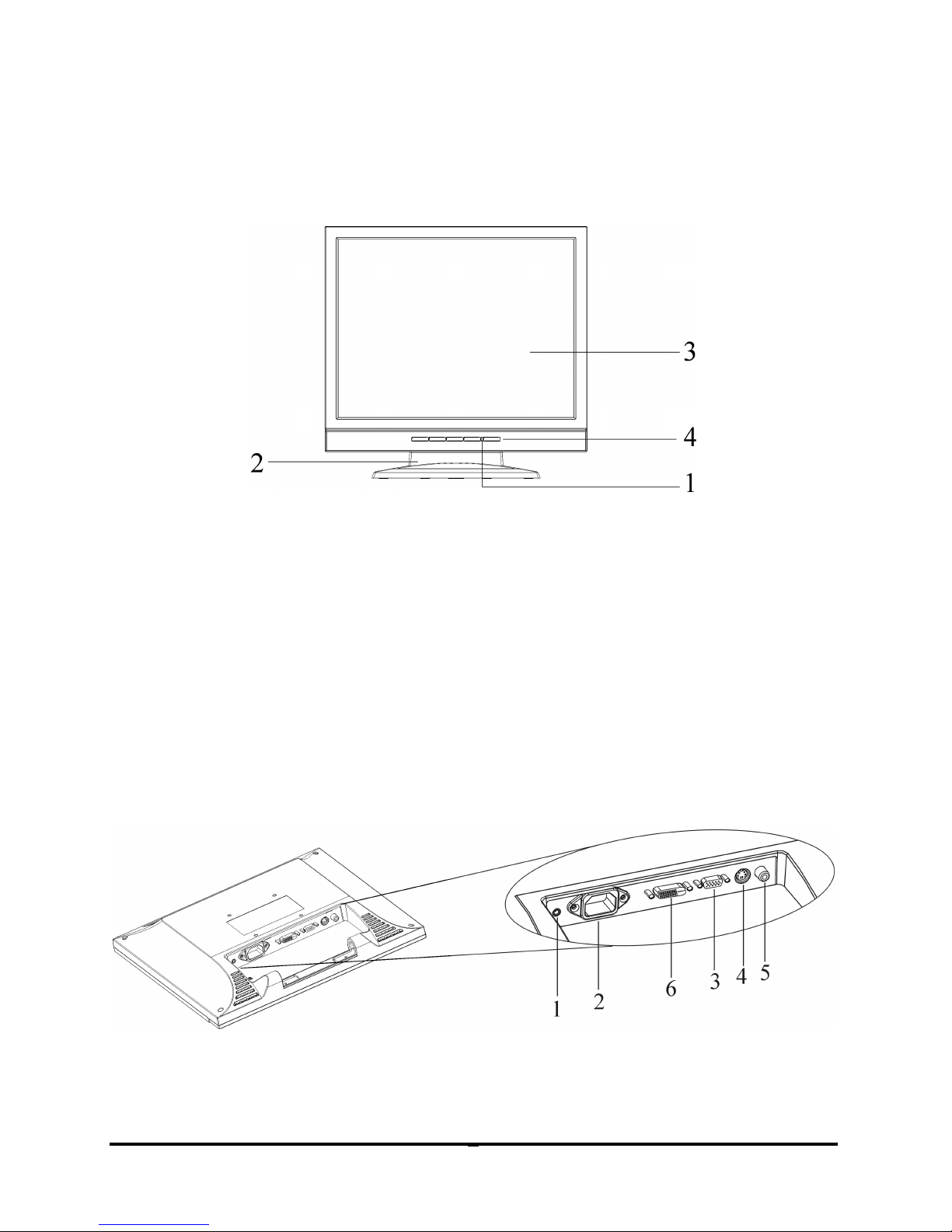
The LCD Multimedia Monitor — Front View
Figure 1-1: The LCD multimedia Monitor Front View
1. Power-On Indicator
This LED indicator stays lit when the power is on and blinks
when the LCD multimedia monitor is in power saving mode.
2. Monitor Stand
3. LCD Screen
4. LCD Multimedia Monitor Control Panel
Refer to Chapter 2 for a detailed.
The LCD Multimedia Monitor — Rear View
Figure 1-2: LCD Multimedia Monitor Rear View
Page 9
3
1. Audio Line-in
2. AC Power Jack
3. VGA (Analog) Cable With 15-Pin D-Sub VGA Connector (Male)
4. S-Video connector
5. AV connector
6. Digital VGA (DVI) Cable Connector (Optional)
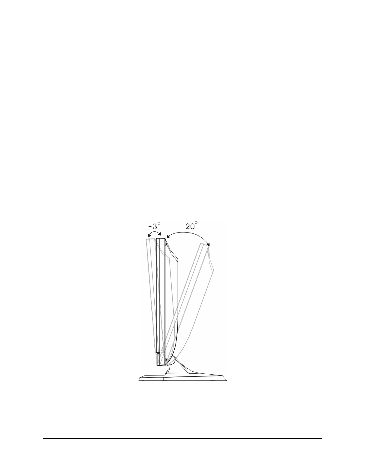
Adjusting the Tilting Angle
The LCD multimedia monitor’s angle settings range from -3° to 20°. See Figure 1-3.
Figure 1-3: Tilting the Monitor
Page 10

4
Raising Your Monitor to an Upright Position and
Adjusting Monitor Angle
Page 11

5
Power Management System
The LCD multimedia monitor complies with the VESA DPMS power management
proposal.
When the LCD multimedia monitor is in power saving mode or detects an incorrect
timing, the monitor screen will be blank and the power LED indicator starts blinking.
Page 12

6
CHAPTER 2
The Display Controls
LCD Multimedia Monitor Control Panel
Figure 2-1: The LCD Monitor Panel
1. OSD Menu Button
Press this button to pop up the OSD (On-Screen Display) menu.
This button is also a Function Select button.
2. Adjustment Control Buttons
These two buttons allow you to adjust the selected control
functions in the OSD.
3. Function Select Buttons
These two buttons allow you to select the control functions in
the OSD. Press either button to scroll through the main menu
and submenu items
.
4. Power Switch
Push the power switch to turn the monitor on and off. This
switch is also a hot-key button to close the OSD menu while the
OSD appears.
Page 13

7
Adjusting the Monitor’s Display
OSD Main Menu
To access the OSD main menu, press the OSD Menu button. Use the Function Select
buttons to scroll between the OSD main menu options. The option that is currently
selected is blinking.
Pressing one of adjustment control buttons causes the following screen to appear:
Figure 2-2: The OSD Main Menu
◆ANALOG MODE:
When analog signal input is selected.
MONITOR-CONTROL Option
The Monitor-Control option allows you to adjust the LCD monitor’s display settings.
Press Adjustment control button to display the submenu.
AUTO-ADJUST: Press the adjustment control button to let the
monitor determine and select the settings that are most appropriate
for your system requirements.
Page 14

8
H-POSITION: To move the LCD monitor’s display left or right
on a horizontal plane.
V-POSITION: To move the LCD monitor’s display up or down
on a vertical plane.
PHASE: To adjust the focus and clarity of the display.
CLOCK: To adjust the display pixel alignment.
RESET: To reset all of the Monitor-Control submenu settings to
the factory default.
GRAPHIC/TEXT: Press the adjustment control button to switch
between text and graphic display modes.
PORT-SELECT: To select video source by pressing adjustment
button to switch DVI (Optional), analog, video (CVBS) or S-Video
signal input.
EXIT: To exits the Monitor-Control submenu.
OSD-CONTROL Option
The OSD-Control menu option lets you adjust the position of the OSD on the screen.
Press the Adjustment control button to display the submenu.
Use the Function Select buttons to select one of the following
submenu options:
OSD-H-POSITION: To change the position of the OSD on a
horizontal plane.
OSD-V-POSITION: To change the position of the OSD on a
vertical plane.
OSD-TIMER: The OSD menu display time can be set at 5, 10, 15,
20, 25 or 30 seconds.
Page 15

9
EXIT: To exit the OSD-Control submenu.
GRAPHIC-CONTROL Option
The Graphic-Control option lets you make adjustments that effect the contrast,
brightness and color of the LCD monitor’s display.
Press the Adjustment control button to display the submenu.
CONTRAST: To adjust the contrast level of the display screen.
BRIGHTNESS: To adjust the light level on the display screen.
COLOR: To select the LCD monitor’s color display. The
available options are 9300, 6500 and User. Selecting the user
option lets you make individual adjustments to the R, G and B
items.
GAIN R, G and B ADJUST: To make individual adjustments to
the Red, Blue, Green (RGB) gain for the color temperature.
AUTO LEVEL: To adjust automatically to perfect the white
balance display.
RESET: To reset all of the Graphic-Control submenu settings to
the factory default.
EXIT: To exit the Graphic-Control submenu.
MISC-CONTROL Option
The Misc-Control menu option lets you select the OSD display language, adjust the
audio volume setting and view system information.
Page 16

10
Press the Adjustment control button to display the submenu.
LANGUAGE: The supported languages include German,
English, French, Spanish, Italian and Japanese.
AUDIO VOLUME: To increase or decrease the volume of the
LCD monitor’s sound system.
INFORMATION: To indicate display mode timings and
firmware version.
EXIT: To exit the Misc-Control submenu.
OSD EXIT Option
Use the OSD Exit item to close the OSD menu.
The OSD will disappear by itself if left inactive.
◆DIGITAL MODE (Optional):
When DVI signal input is selected.
MONITOR-CONTROL Option
Press Adjustment control button to display the submenu.
PORT-SELECT: To select video source by pressing adjustment
button to switch DVI (Optional), analog, video (CVBS) or S-Video
signal input.
EXIT: To exits the Monitor-Control submenu.
Page 17

11
OSD-CONTROL Option
The OSD-Control menu option lets you adjust the position of the OSD on the screen.
Press the Adjustment control button to display the submenu.
Use the Function Select buttons to select one of the following
submenu options:
OSD-H-POSITION: To change the position of the OSD on a
horizontal plane.
OSD-V-POSITION: To change the position of the OSD on a
vertical plane.
OSD-TIMER: The OSD menu display time can be set at 5, 10, 15,
20, 25 or 30 seconds.
EXIT: To exit the OSD-Control submenu.
GRAPHIC-CONTROL Option
The Graphic-Control option lets you make adjustments that effect the contrast,
brightness and color of the LCD monitor’s display.
Press the Adjustment control button to display the submenu.
CONTRAST: To adjust the contrast level of the display screen.
BRIGHTNESS: To adjust the light level on the display screen.
RESET: To reset all of the Graphic-Control submenu settings to
the factory default.
EXIT: To exit the Graphic-Control submenu.
Page 18

12
MISC-CONTROL Option
The Misc-Control menu option lets you select the OSD display language, adjust the
audio volume setting and view system information.
Press the Adjustment control button to display the submenu.
LANGUAGE: The supported languages include German,
English, French, Spanish, Italian and Japanese.
AUDIO VOLUME: To increase or decrease the volume of the
LCD monitor’s sound system.
INFORMATION: To indicate display mode timings and
firmware version.
EXIT: To exit the Misc-Control submenu.
OSD EXIT Option
Use the OSD Exit item to close the OSD menu.
The OSD will disappear by itself if left inactive.
◆VIDEO or S-VIDEO MODE:
When Video or S-Video signal input is selected.
MONITOR-CONTROL Option
Press Adjustment control button to display the submenu.
PORT-SELECT: To select video source by pressing adjustment
button to switch DVI (Optional), analog, video (CVBS) or S-Video
signal input.
Page 19

13
EXIT: To exits the Monitor-Control submenu.
OSD-CONTROL Option
The OSD-Control menu option lets you adjust the position of the OSD on the screen.
Press the Adjustment control button to display the submenu.
Use the Function Select buttons to select one of the following
submenu options:
OSD-H-POSITION: To change the position of the OSD on a
horizontal plane.
OSD-V-POSITION: To change the position of the OSD on a
vertical plane.
OSD-TIMER: The OSD menu display time can be set at 5, 10, 15,
20, 25 or 30 seconds.
EXIT: To exit the OSD-Control submenu.
VIDEO-CONTROL Option
Press the Adjustment control button to display the submenu.
CONTRAST: To adjust the contrast level of the display screen.
BRIGHTNESS: To adjust the light level on the display screen.
HUE: To adjust the hue level you prefer.
Page 20

14
SATURATION: To adjust the color level you prefer.
SHARPNESS: Press the adjustment button to optimize the
sharpness for your specific application.
RESET: To reset all of the Video-Control submanu settings to the
factory default.
EXIT: To exit the Video-Control submenu.
MISC-CONTROL Option
The Misc-Control menu option lets you select the OSD display language, adjust the
audio volume setting and view system information.
Press the Adjustment control button to display the submenu.
LANGUAGE: The supported languages include German,
English, French, Spanish, Italian and Japanese.
AUDIO VOLUME: To increase or decrease the volume of the
LCD monitor’s sound system.
INFORMATION: To indicate display mode timings and
firmware version.
EXIT: To exit the Misc-Control submenu.
OSD EXIT Option
Use the OSD Exit item to close the OSD menu.
The OSD will disappear by itself if left inactive.
Page 21

15
Note:
1. No Video
When the monitor is ON and there is
no Video signal received, the
following message will be displayed.
2. Signal out of monitor’s supported range (Please refer to Addendum)
When the frequency range of the signal is out of the monitor’s specifications, the
display will show the following message on two cases:
Case 1:
The incoming frame rate is higher
than 75Hz.
In this case, the screen display may
not be centered and a warning
message appears.
Case 2:
The incoming resolution is higher
than 1280x1024.
In this case, the video data will be turned
off and a warning message appears at
center.
Page 22

16
Hot-Key Buttons for Quick Adjustment of Monitor
Settings.
(〝AUTO-ADJUST〞hot-key is effective only when analog
input signal is selected for application)
1. "Auto-adjust" hot-key button:
Press button 2 to apply the monitor setting
automatically. A small “AUTO-ADJUST”
OSD is also displayed.
2. "Adjust-volume" hot-key button:
Press button 3 to allow you to adjust the
audio volume directly. A small “AUDIOVOLUME” OSD is also displayed.
3.Video "Source" hot-key button:
Press button 4 to allow you to switch DVI,
analog, video and S-Video signal input
directly and the selected "input signal" is also
displayed on the top left corner. If there is no
video signal received, the "input signal"
display will be disappeared and then the
following message will be displayed.
* To close the small OSD windows, press the power button (button 5).
Page 23

17
APPENDIX A
Troubleshooting
Troubleshooting Procedures
This LCD monitor comes pre-adjusted with standard VGA timing. Due to output
timing differences among various VGA cards, you may initially experience an
unstable or unclear display when a new display mode or new VGA card is selected.
Before applying any of the following troubleshooting procedures, you should first
apply the Auto Adjust option in the OSD menu.
PROBLEM: Display is Unclear and Unstable
To stabilize and clarify your display, follow this procedure:
1. In Windows, enter the windows shut down screen.
2. Open the OSD and select the Clock function. Press one of the
Adjustment Control buttons until the dark vertical bands
disappear.
3. Select the Phase function and press one of the Adjustment
Control buttons until horizontal dark and light lines appear. The
number of lines increases as you press the button. Press the
other Adjustment Control button until the lines disappear and
you have a clear display.
PROBLEM: There is no LCD Display
If there is no display on the LCD, refer to the following:
1. Make sure that the power indicator on the LCD monitor is lit,
all connections are secure, and the system is running on the
correct timing. Refer to the Addendum for information on
timing.
Page 24

18
2. Turn off the LCD monitor and then turn it back on again. Press
the OSD Menu button (refer to Chapter 2) once and then press
either Adjustment Control button several times. If there is still
no display, press the other Adjustment Control button several
times.
3. If step 2 doesn’t work, connect your PC system to another
external CRT. If your PC system functions properly with a CRT
monitor but it does not function with the LCD monitor, and the
LCD monitor’s power LED is blinking, the output timing of the
PC’s VGA card may be out of the LCD’s synchronous range.
Change to one of the alternate modes, listed in the Addendum,
or replace the VGA card and repeat steps 1 and 2.
4. If the power LED is not lit, check that the AC power connector
is securely connected. Verify that the AC adapter LED is lit. If
the AC adapter LED is not lit, please contact your dealer for
assistance.
PROBLEM: There is no Video Signal
1. Make sure the connected video device is on and connected
correctly.
2. Make sure the video source is selected to the connected video
device correctly.
Page 25

19
APPENDIX B
Technical Information
LCD Monitor Specifications
LCD Panel 17-inchTFT
Control
Functions
Power
Software switch with LED indicator (toggle ON/OFF)
Main Menu Submenu
ANALOG MODE:
MONITOR-CONTROL
AUTO-ADJUST, H-POSITION, VPOSITION, PHASE, CLOCK, RESET,
GRAPHIC / TEXT, PORT-SELECT, EXIT
OSD-CONTROL
OSD-H-POSITION, OSD-V-POSITION,
OSD-TIMER, EXIT
GRAPHIC-CONTROL
CONTRAST, BRIGHTNESS, COLOR,
GAIN R, G and B ADJUST, AUTO LEVEL,
RESET, EXIT
MISC-CONTROL
LANGUAGE, AUDIO-VOLUME,
INFORMATION, EXIT
OSD EXIT
DIGITAL MODE (Optional):
MONITOR-CONTROL
PORT-SELECT, EXIT
OSD-CONTROL
OSD-H-POSITION, OSD-V-POSITION,
OSD-TIMER, EXIT
GRAPHIC-CONTROL
CONTRAST, BRIGHTNESS, RESET,
EXIT
MISC-CONTROL
LANGUAGE, AUDIO-VOLUME,
INFORMATION, EXIT
OSD EXIT
VIDEO or S-VIDEO MODE:
MONITOR-CONTROL PORT-SELECT, EXIT
OSD-CONTROL
OSD-H-POSITION, OSD-V-POSITION,
OSD-TIMER, EXIT
VIDEO-CONTROL
CONTRAST, BRIGHTNESS, HUE,
SATURATION, SHARPNESS, RESET,
EXIT
MISC-CONTROL
LANGUAGE, AUDIO-VOLUME,
INFORMATION, EXIT
On-Screen
Display (OSD)
OSD EXIT
Page 26

20
Display Area 337.920 mm x 270.336 mm (17.0-inch diagonal)
Display Colors 16M
Video Input VGA, DVI (Optional), S-Video, AV
Scanning
Frequency
(Analog mode)
24-80K
56-75
Scanning
Frequency
H/V, Hz
(Digital mode)(Optional)
31-80K
56-75
Power
Management
Meets VESA DPMS
Power
Consumption
ON : 40W max. OFF/Power Saving Mode: Less than 5W
(Measured from AC inlet)
Dimensions
(Approx.)
372mm (W) x 385mm (H) x 210mm (D)
Net Weight (Kg)
(Approx.)
5+1
Power Supply Built-In Universal Input Off-Line Power Supply
Options Desktop and wall-mount (VESA type)
Environment Operating/Storage
Temperature: 0/-20 to
40/60° C
Relative Humidity:
10% to 85%
Altitude: 0-12,192m
(0-40,000ft)
Audio Audio in x 1, 1.0W speaker x 2 with built-in amplifier
Regulatory
cUL, CE, FCC B DoC
Page 27

21
APPENDIX C
Supported Timing
Ite
m
Standards Resolution
Dot
Clock
(MHz)
Vertical
Scanning
Frequency
(Hz)
Horizontal
Scanning
Frequency
(kHz)
Sync
Polarity or
composite
sync (H/V)
Operatin
g Mode
1 NEC PC98 640x400 25.20 70.15 31.50 -/- A/D
2 NEC PC98 640x400 21.05 56.42 24.83 -/- A
3 MAC 13”
mode
640x480 30.24 66.67 35.00 -/- A/G
4 MAC 16”
mode
832x624 57.28 74.55 49.73 -/- A/G
5 MAC 17”
mode
1024x768 80.00 75.02 60.24 -/- A/G
6 VGA 640x350 25.18 70.09 31.47 +/- A/D
7 VGA 640x400 25.18 70.09 31.47 -/+ A
8 VGA 640x480 25.18 59.94 31.47 -/- A/D
9 VESA 640x480 31.50 72.81 37.86 -/- A/D
10 VESA 640x480 31.50 75.00 37.50 -/- A/D
11 VESA 800x600 36.00 56.25 35.16 +/+ A/D
12 SVGA 800x600 40.00 60.32 37.88 +/+ A/D
13 VESA 800x600 50.00 72.19 48.08 +/+ A/D
14 VESA 800x600 49.50 75.00 46.88 +/+ A/D
15 VGA 720x400 28.32 70.09 31.47 -/+ A
16 XGA 1024x768 65.00 60.00 48.36 -/- A/D
17 VESA 1024x768 75.00 70.07 56.48 -/- A/D
18 VESA 1024x768 78.75 75.03 60.02 +/+ A/D
19 1024x768 71.64 66.13 53.96 +/+ A/D
20 VESA 1152x864 108.00 75.00 67.50 +/+ A/D
21 1152x870 100 75.06 68.68 -/- A/D
22 VESA 1280x960 108.0 60.0 60.0 +/+ A/D
23 VESA 1280x1024 108.0 60.02 63.98 +/+ A/D
24 VESA 1280x1024 127.0 69.85 74.88 +/+ A/D
25 VESA 1280x1024 135.0 75.03 79.98 +/+ A/D
26 SUN 1024x768 64.13 59.98 48.29 H+V A
27 SUN 1024x768 74.25 70.04 56.59 H+V A
* A=Analog Mode; D=Digital Mode (Optional); G=Sync On Green Mode
* Once a mode is optimized, 50
there is no need to make any further adjustment as long as the VGA card remains unchanged.
* Specifications are subject to change without notice.
Page 28

6200564280
TATUNG COMPANY OF AMERICA
2850 El Presidio ST.
Long Beach, CA 90810
(800) 827-2850
www.tatungusa.com
 Loading...