

Page 1

TATUNG TDR series Digital Recording System Page 0
TDR
-
22XX
series
TATUNG COMPANY OF AMERICA. INC
Digital Recording System
Installation and Operation Manual
V 1.03 03/10/2003
2850 El Presidio St., Long Beach CA 90810 USA
Tel: 310-637-2105 Fax: 310 -638-2180
www.tatungusa.com
Page 2

TATUNG TDR series Digital Recording System Page 0
Page 3

TATUNG TDR series Digital Recording System Page 0
Chapter 1:
Installation
1
CONTENTS
Step 1 Connect the cables 2
Chapter 2: Watch Mode 3
Chapter 3: Setup Mode 9
3.2 Schedule 13
Chapter 4: Search Mode 26
4.1 Channel Play back window 28
4.2 Buttons on Play Back Console 29
4.3 Date/Time 30
4.4 Log 32
4.5 Save Disk 33
4.6 Print 34
4.7 Storage Capacity 35
4.8 Exit 35
Chapter 5: Backup Mode 36
5.1 Auto Backup 37
5.2 AVI Backup 39
5.3 Explorer 40
5.4 Cancel 40
Chapter 6: Control Mode 41
6.1 Camera Control 41
6.2 Exit 42
Appendix
A: Alarm Connector Configuration 43
B: AVI PLAYER Instruction 45
C: Backup Viewer Instruction 49
D: Technical Specification 55
E: Charts for recordint time 57
Step 2 Turn on the system 2
2.1 Channel display window 5
2.2 Selection of Split screen 6
2.3 Motion Tracker 7
2.4 Mode switch button 8
2.5 On/Off button 8
3.1 Channel 11
3.3 Speed 15
3.4 Color 17
3.5 Motion 18
3.6 P/T/Z Control 20
3.7 Password 21
3.8 Voice 24
3.9 Exit 25
Page 4

TATUNG TDR series Digital Recording System Page 0
Page 5
TATUNG TDR series Digital Recording System Page 1
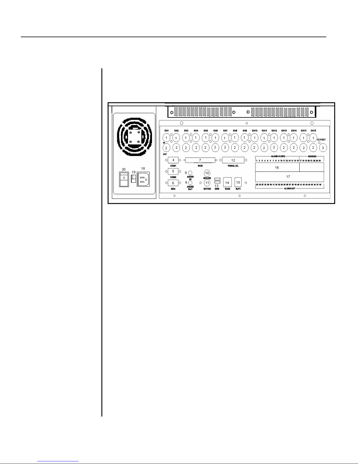
Place the Digital Recording System on a flat surface or
* For TDR
-
2209 there are only 9 camera Inputs and 9 Loop through outputs on
CHAPTER 1: INSTALLATION
mount it on the 19” rack.
the back board. For TDR-2204 there are only 4 camera Inputs and 4 Loop
through outputs on the back board.
1. Camera Inputs
2. Loop Through Outputs
3. CCTV Monitor Output
4. COM Series Port 1
5. COM Series Port 2
6. XGA Output
7. SCSI Port
8. Audio In
9. Audio Out
10. Mouse (PS/2)
11. Keyboard (PS/2)
12. Parallel (Printer) Port
13. USB Ports (2)
14. Network Port (RJ-45)
15. Phone Port (RJ-11)
16. Alarm Inputs
17. Alarm Outputs
18. AC Power Input
19. 115/230 VAC Power Switch (option)
20. Power Supply Switch (option)
Page 6
TATUNG TDR series Digital Recording System Page 2
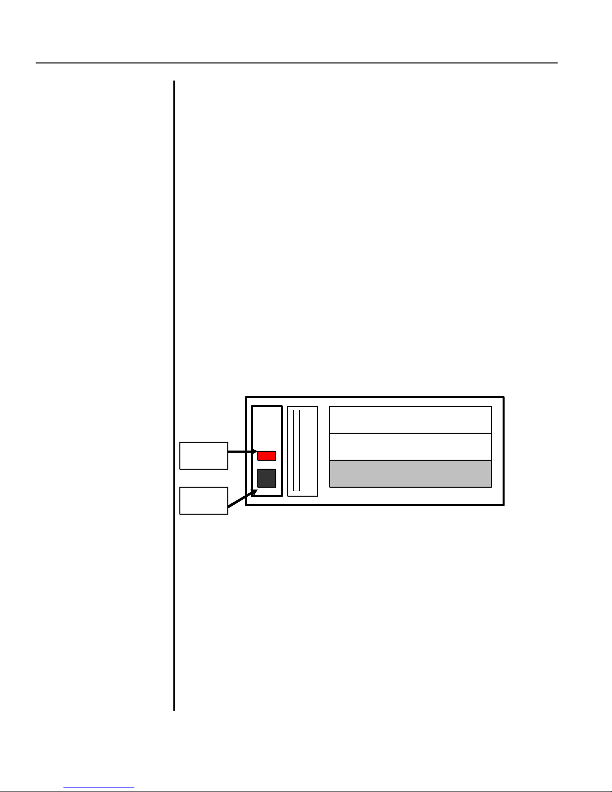
Removable Storage
CDRW
Step 1: Connect the Cables
Connect all the necessary signal cables , inputs, and devices into the correct
ports.
* For TDR-2209 there are only 9 camera Input s and 9
Loop through outputs on the back board. For TDR-2204
there are only 4 camera Inputs and 4 Loop through
outputs on the back board.
* For TDR-2204 there are only 8 alarm inputs and 4
alarm outputs on the back board. For TDR-2209 and
TDR-2216 there are 16 alarm inputs and 8 alarm
outputs.
Step 2: Turn on the System
Turn on the power by pushing the power button on the front panel.
Reset
Power
* For the storage more than 320 GB, there is no
removable kit available because two more Hard
Drives are used in one system.
Page 7
TATUNG TDR series Digital Recording System Page 3
CHAPTER 2:
WATCH MODE
The buttons and icons on the screen are described
below:
Note
: For TDR
-
2209 there are
Note
: For TDR
-
2209, the Button
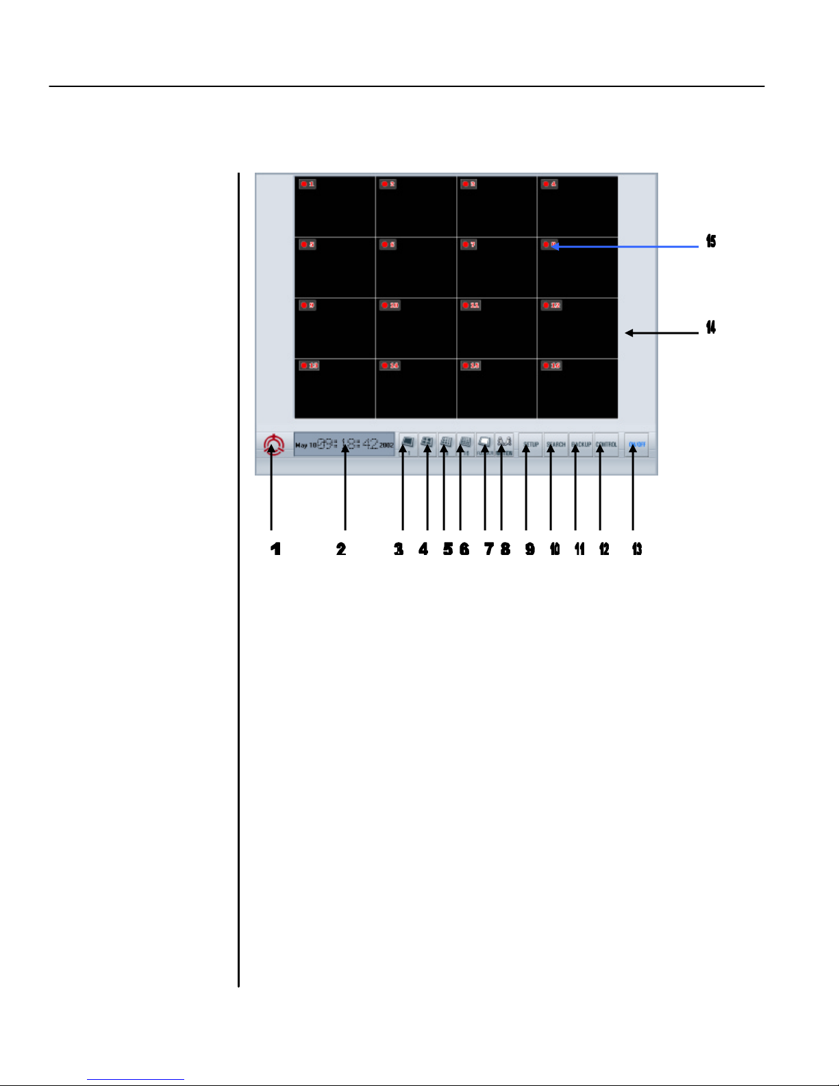
Turn on the system. The main screen of TATUNG TDR -22XX series will appear as shown below.
only 9 channels divided within
the screen. For TDR-2204 there
are only 4 channels divided
within the screen
for 9 Sequence and the button
for 16 will show the all 9
channels at same time. For
TDR -2204, the Button for 4, 9,
and 16 Sequence will show all 4
channels at same time.
1. Company LOGO
This is the logo of TATUNG Company of America.
2. DATE/TIME Window
This window displays the date and time (military time).
3. 1 Sequence Button
Click to select the 1-window (1x1) format. Only 1 camera can be
displayed at a time. The sequential dwell time can be adjusted in
SETUP mode.
4. 4 Sequence Button
Click to select the 4-window (2x2) format. Up to 4 cameras can be
displayed at the same time. The sequential dwell time can be adjusted
in SETUP mode.
5. 9 Sequence Button
Click to select the 9-window (3x3) format. Up to 9 cameras can be
displayed at the same time. The sequential dwell time can be adjusted
in SETUP mode.
6. 16 Button
Click to select the 16-window (4x4) format. Up to 16 cameras can be
displayed at the same time. The sequential dwell time can be adjusted
in SETUP mode.
Page 8

TATUNG TDR series Digital Recording System Page 4
7.
Full SCR Button
This button allows you to hide all buttons and icons and enlarge the
Click to enable the motion tracking function. This is a very powerful
function which allows you to track a moving object from one channel
to another. All image windows this object passed by will be enlarged
one by one.
Click to turn off the entire system.
display windows to the FULL SCREEN. To get back to the normal
screen you must right click. Once you get the full screen, if you LEFT
click, the screen will not go back to normal; instead, the picture the
mouse arrow is sitting on will be enlarged to full screen.
8. Motion Button
9. Setup Button
Click to switch to SETUP MODE. The setup mode includes buttons
for CHANNEL, SCHEDULE, SPEED, COLOR, MOTION, P/T/Z
PROTOCOL, PASSWORD, and VOICE. With these buttons your
system can be custom-programmed to fit your operation needs.
10. Search Button
Click to switch to SEARCH MODE. In this mode, you may either use
either the LOG or DATE/TIME button to check the image database
and access the recorded images within seconds. You can either
PRINT or SAVE the images found to a floppy disk for your emergency
needs. You can also check the capacity of storage used/available
with the STORAGE button.
11. Backup Button
Click to switch to BACKUP MODE. In this mode, you may either
choose the AUTO backup function to save images to a second
removable hard disk or choose the AVI backup function to save
images onto a CDRW available from this system.
12. Control Button
Click to switch to CONTROL MODE. In this mode the
PAN/TILT/ZOOM features of each camera can be controlled by
clicking the appropriate buttons on the screen.
13. On/Off Button
14. Display windows
Display camera images on 1, 4, 9 or 16 windows depending on your
selection. Left clicking a window will enlarge the picture in that
specific window. And left clicking again will return the picture back to
the normal size. RIGHT clicking any window will hide all buttons and
icons and enlarge all pictures to full screen. And right click again will
go back to normal screen
15. On Screen Display (OSD)
Display the camera name and recording status. The recording status
indicates whether the camera is active or inactive and the recording
method it is recording (continuous , motion, or alarm sensor
recording).
Page 9

TATUNG TDR series Digital Recording System Page 5
1.
Channel
(Camera)
name
2.1 Channel display window
1. Channel (Camera) name
2. Image display window
3. Record status lamp
Identify the name for each channel. You may assign the channel name in
SETUP mode.
2. Image Display window
This area displays the image coming from the corresponding camera.
3. Recording status lamp
This lamp turns red when continuously recording
When motion recording, this lamp becomes blue and transparent.
(on and off)
When sensor recording, this lamp turns yellow and transparent .
(on and off)
Page 10
TATUNG TDR series Digital Recording System Page 6
Note: You can
always
use
Note
: On all
Ch Display, left
Note
: For TDR
-
2209, the 9
and
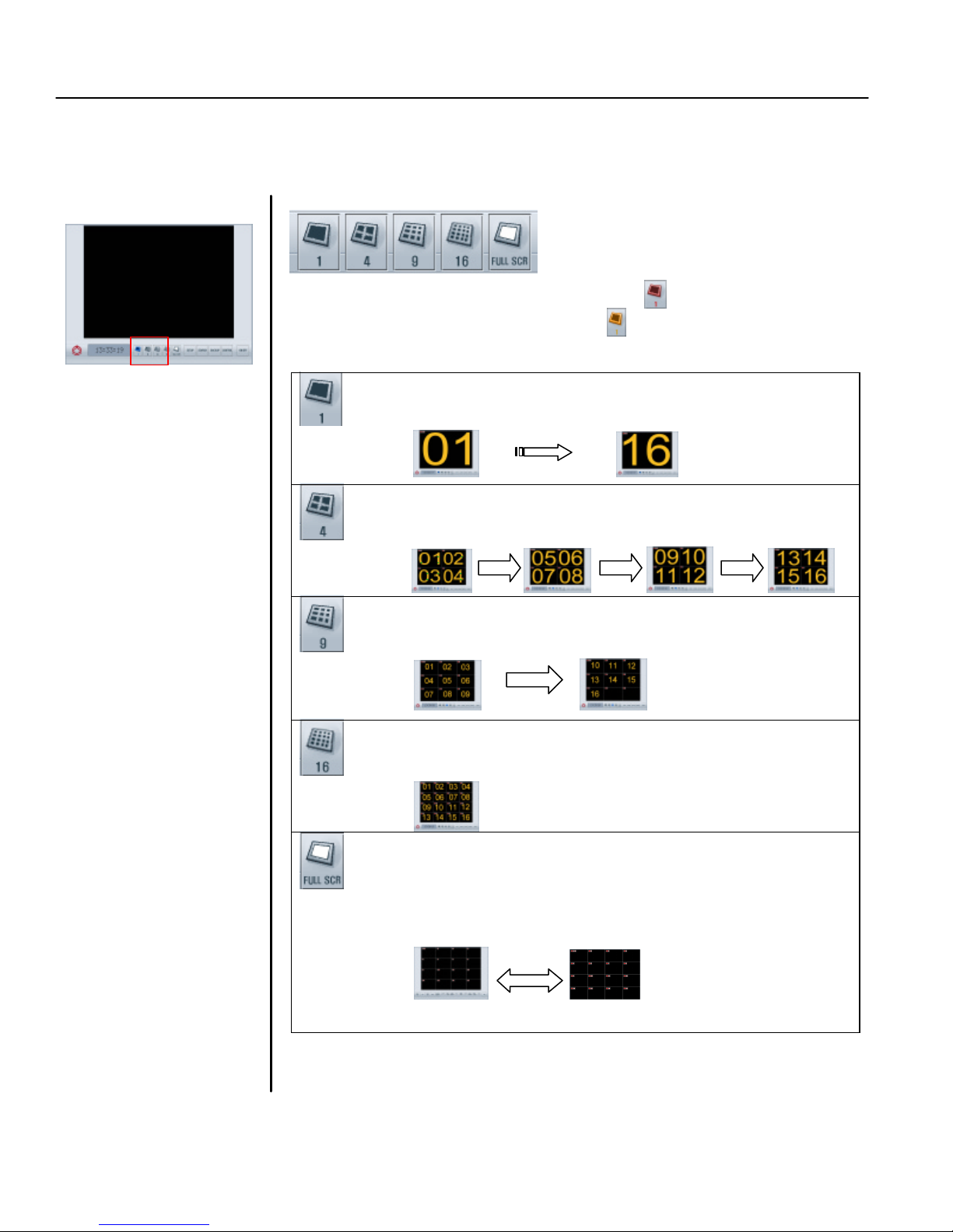
2.2 Selection of Split screen
Selection of window division mode that is available in 1 division window (sequence from channel 1
to channel 16), 4 window, 9 window, 16 window, and Full screen display.
Click these buttons one time (the button turns RED) to get sequential display.
Click second time (the button turns ORANGE) to stop sequence. More Click to
switch between sequence (RED) and stop sequence (ORANGE)
click a specific camera and
the image of this camera will
be enlarged without
sequencing. And left-click
again can go back to the
normal status.
16 sequence button w ill show all
9 channels at same time. For
TDR -2204, the 4, 9, and 16
sequence button will show all 4
channels at same time.
One-window sequence
Four-window sequence
Nine-window sequence
All channe l display
the right-click button on the
mouse to switch between
the Full screen status and
the normal screen status.
FULL screen
Click this button to hide all buttons and icons and enlarge the display
windows to FULL screen. You must right click on the mouse or touch
pad to go back to the normal.
Page 11

TATUNG TDR series Digital Recording System Page 7
Click on this button to enable the motion tracking function.
Note
: To enable this
2.3 Motion Tracker
This function allows you to track the path of a moving object from one channel to another. The
specific image window that the objec t activates will be enlarged. Therefore, the object will always be
displayed on an enlarged window.
function, all channels
must to be programmed
to motion recording.
Page 12
TATUNG TDR series Digital Recording System Page 8
Click
one of these buttons to perform its specific function
Click on this button
to shutdown the syst
em. Confirm
with
“YES” as the system
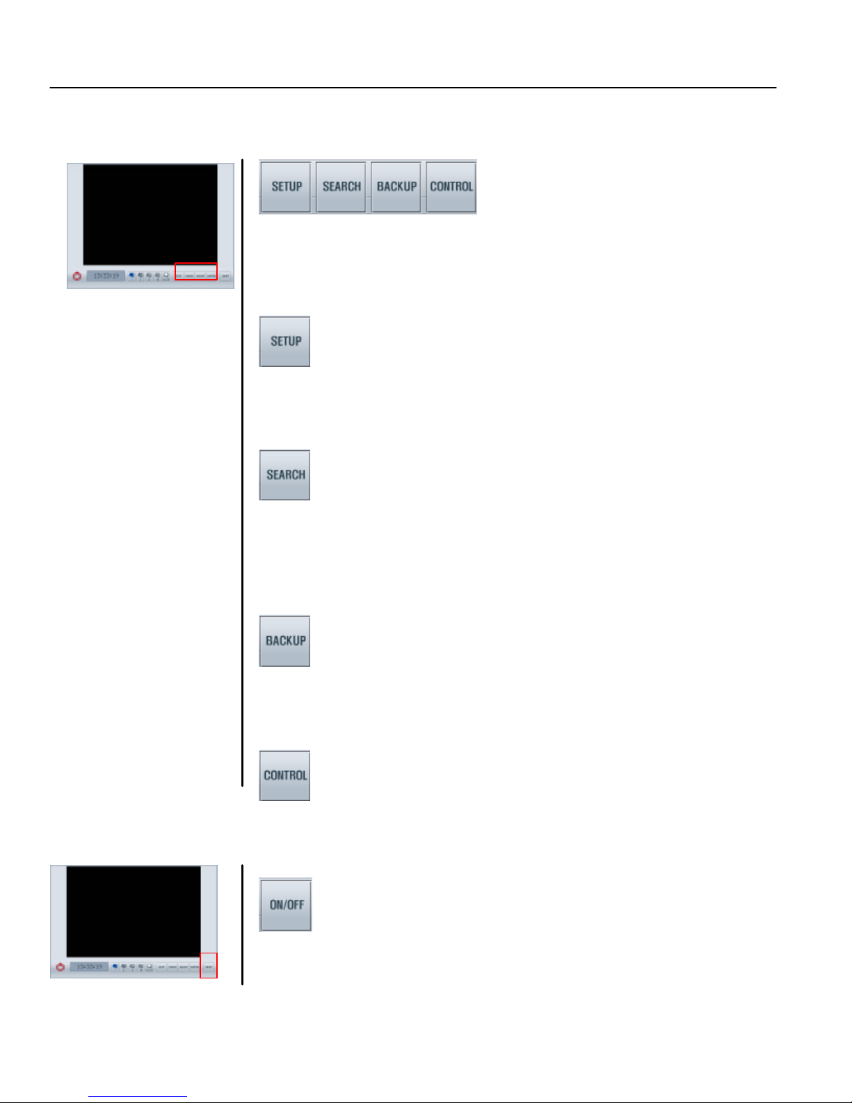
2.4 Mode Switch button
There are four function modes that can be selected in this system.
SETUP: Click to switch to SETUP MODE. The setup mode
includes the buttons: CHANNEL, SCHEDULE, SPEED,
COLOR, MOTION, P/T/Z PROTOCOL, PASSWORD, and
VOICE. With these buttons , your system can be custom programmed to fit your specific operation requirements.
SEARCH: Click to switch to SEARCH MODE. In this mode, you may
either use the LOG button to search the image database
or use the DATE/TIME button to retrieve the recorded
images within seconds. The images found may either be
printed out or saved to a floppy disk for your emergency
needs. The status of the storage drive can be checked by
the STORAGE button.
BACKUP: Click to switch to BACKUP mode. You can backup the
data to the other storage or other type of media which is
available for this system. This mode include the autobackup function, immediate AVI type backup function and
have a windows explorer opened for your convenience.
CONTROL: Click to switch to CONTROL MODE. In this mode the
PAN/TILT/ZOOM of specific cameras can be controlled
by clicking the appropriate buttons on the screen.
2.5 ON/OFF Button
prompts: “ARE YOU SURE?” to complete the shutdown the DVR system.
Page 13
TATUNG TDR series Digital Recording System Page 9
CHAPTER 3: SETUP
MODE
The control buttons contained in the main screen are
as
described below:
Note
: For TDR
-
2209, CH 10 to
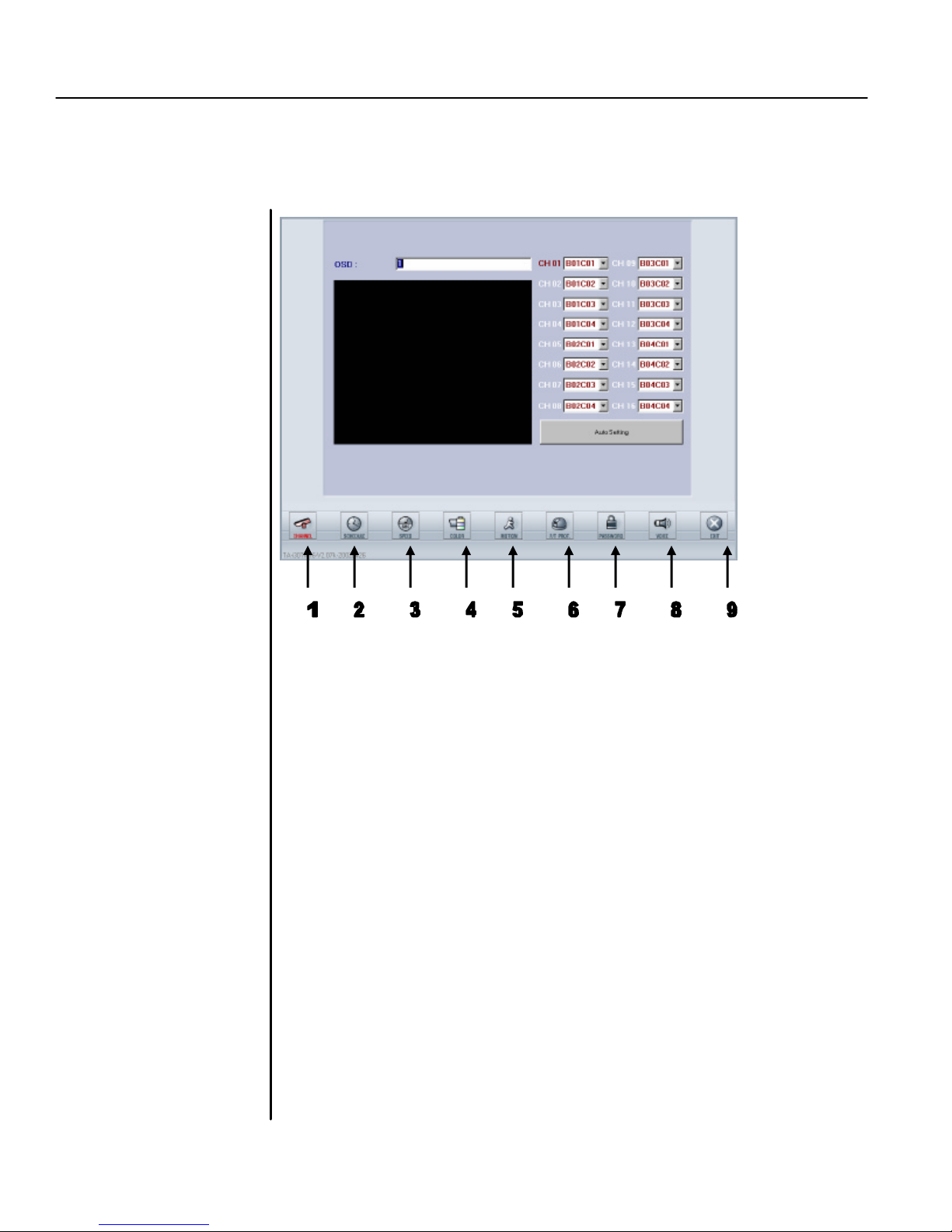
The first screen of the setup mode will be the channel setting screen displayed below
CH 16 will be empty by the
factory’s setting. For TDR-2204,
CH 05 to CH 16 will be empty by
factory’s setting
1. Channel
Click to setup the channel and channel (OSD) name. There are two
different ways to setup the channel: automatically scan or manually
designate. You may also set the name for each channel.
2. Schedule
Click to setup the recording schedules. There are 16 recording groups and
three recording modes (continuous, motion, sensor) that may be separately
set up for your application. Alarm output s can also be set up separately.
3. Speed
Click to setup the recording speed and other options. The recording speeds
include speeds on normal, motion, and sensor recording. You can also set
up the time delay for the display sequence as well as pre alarm, pre motion
and post alarm, post motion recording in this mode.
4. Color
Click to adjust the image attributes including the adjustment of Brightness,
Contrast, Color (saturation), and TINT for each individual channel.
5. Motion
Click to setup the motion function. You can set up each individual
channel’s motion detection area (up to 10 zones for each channel),
sensitivity, and beep time for motion detection.
Page 14

TATUNG TDR series Digital Recording System Page 10
6.
P/T/Z camera protocol
Click to setup the communication port and protocol used to communicate
between TATUNG’s DVR and your specific camera connected.
7. Password
Click to setup the user name and password for multi-level security access.
The passwords are divided into four levels: SETUP, VIEWER, SHUTDOWN,
and REMOTE . Hiding cameras can also be programmed within this setup.
8. Audio
Click to setup the audio recording function.
9. Exit
Click to exit the setup mode and go back to main Watch mode.
Page 15
TATUNG TDR series Digital Recording System Page 11
This is the first
Click to
drop-down
the
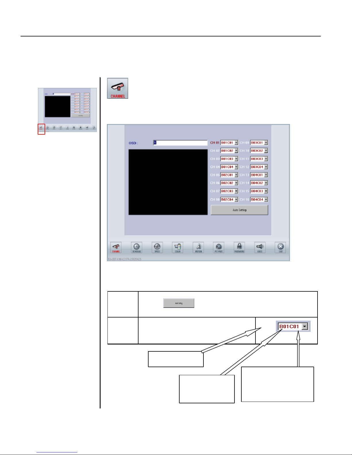
Click this button to start the channel setu
p and the screen will be shown as below.
First Channel
Note
: For TDR
-
2209, CH 10 to
3.1 Channel
This function button (as shown below) can be used to setup the channels. There are two different
types of channel setting: manual or automatic.
CH 16 will be empty by the
factory’s setting. For T DR-2204,
CH 05 to CH 16 will be empty by
factory’s setting
You can setup the channel either by auto setting or manual setting.
1. Setup the Channel
Auto
Setting
Manual
Setting
Click on and setup will be executed automatically
Select the Board (B01-B04) and Channel
(C01-C04) from the list to setup the
Channel Name
Board and first
Camera
CH01
list. Select the Board #
and Camera # from the
list. Then left -click.
Page 16
TATUNG TDR series Digital Recording System Page 12
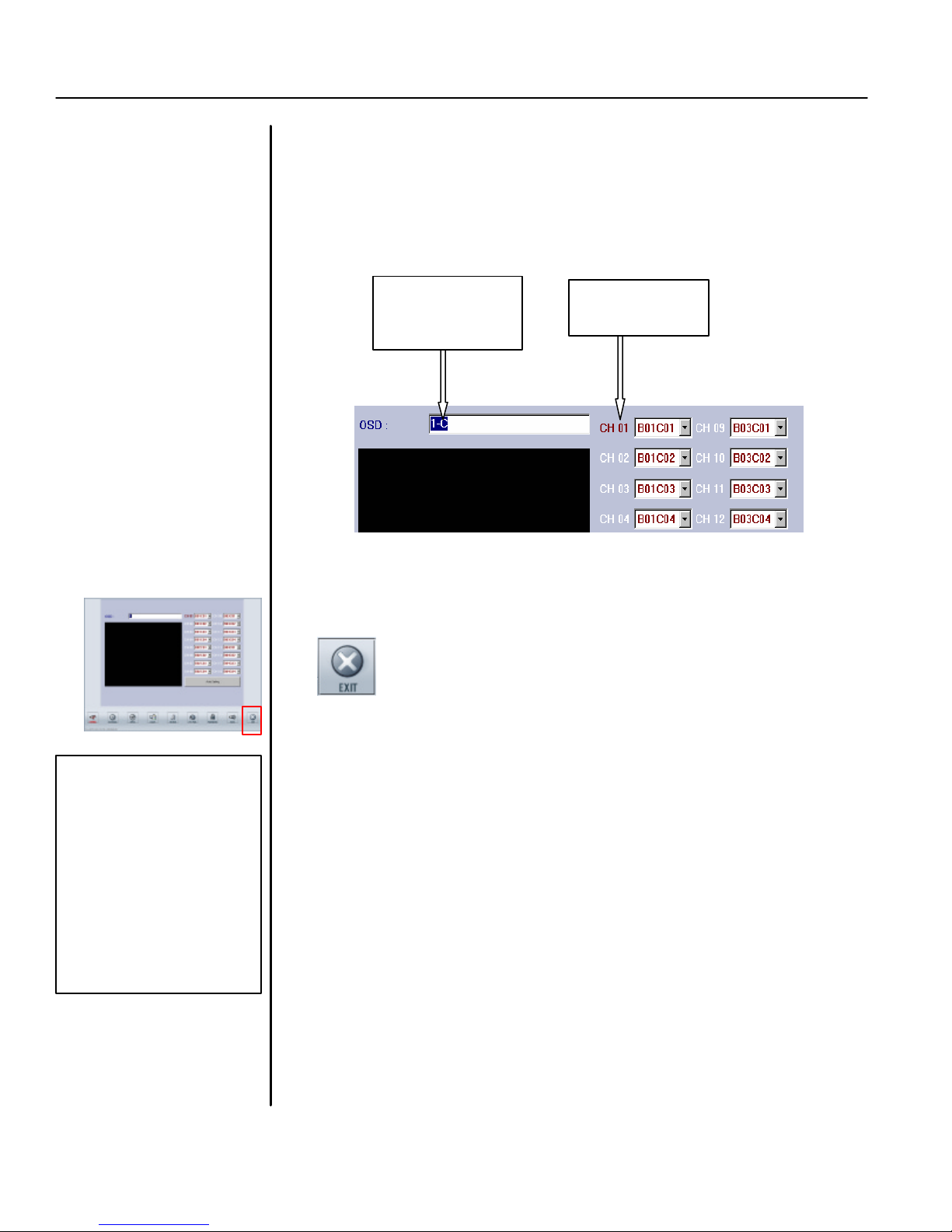
1. Click to
2
. Key in the
Note:
When complete the
2. Setup the name
Setup the channel name with following the procedure
1. Click the channel number
2. Key in the name of the channel
3. Limited to 14 characters including space.
channel name
here
choose channel
3. EXIT
You may click any other icon to exit Channel Setup Mode and go directly into
another setup mode. Click EXIT button, you will be back to Watch Mode.
setup and exit to the LIVE
mode, the system will
spend about 20 second to
compensate and install
the new setting. This
operation may cause the
image of the cameras
stop motion or
discontinuous motion.
The recorded data also
have the same effect.
Page 17
TATUNG TDR series Digital Recording System Page 13
Click on this button to start schedule setup and the screen will display as
Note:
The shutdown time is
Note
: For TDR
-
2209, Camera’s
Note
: Alarm Out
0
9 to 16
is
not
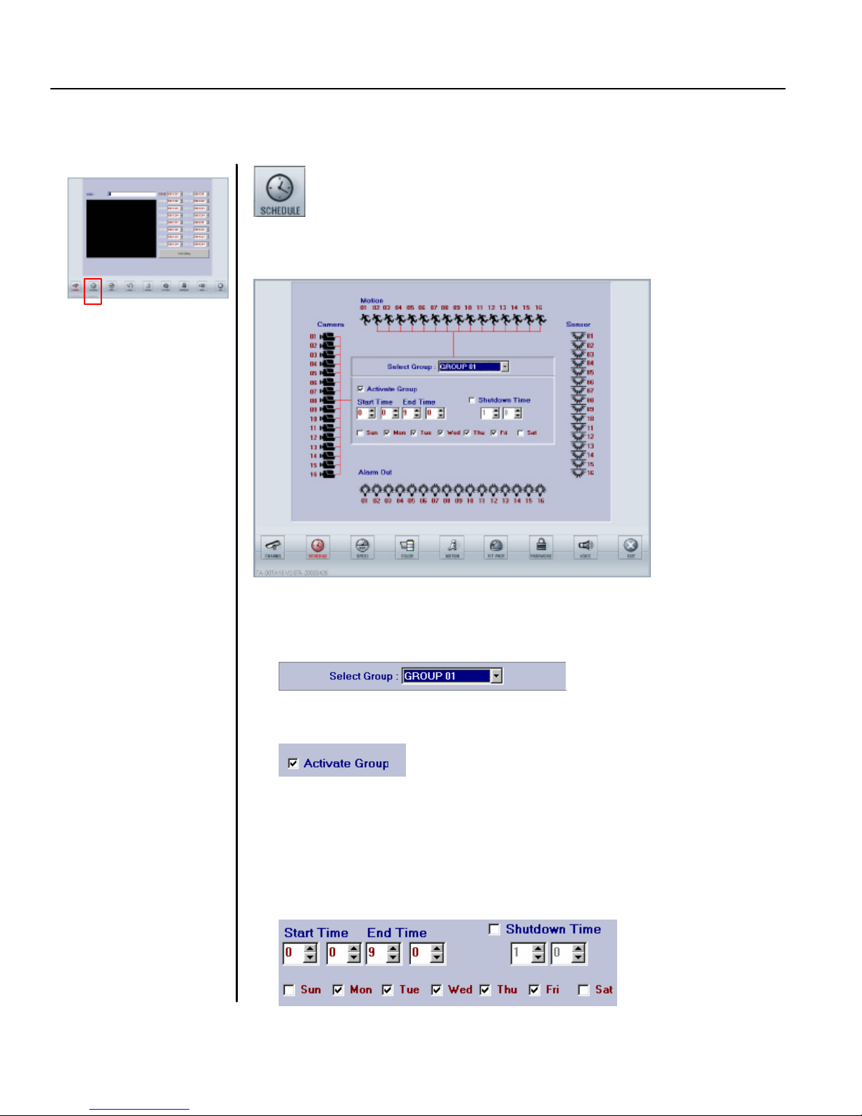
3.2 Schedule
This function button (as shown below ) is used to setup the schedules.
CH 10 to CH 16 and Motion’s
CH 10 to CH 16 will be useless
even if you activate it. For TDR2204, Camera’s CH 05 to CH 16
and Motion’s CH 05 to CH 16 will
be useless even if you activate it.
configured in all TDR-22XX
series DVRs.
to set the time for turning off
the system, which is different
to the restart system.
Select the Group number (total 16 groups are available and
programmable).
Activate the group by checking the box.
follow. (Please follow the 7 steps below)
1. Select the Group
2. Activate Group
3. Schedule the Recording DATE/TIME and DVR Shutdown Time
• Setup the days of the week (Sunday to Saturday) by checking the box of the
day.
• If you want to assign the recording time (default is 24 hours), setup [Start
Time] and [End Time] by using military time system. (00:00 to 00:00
corresponds to 24 hours).
• If you want to assign a shutdown time, check the box of Shutdown Time and
set the shut down time.
Page 18
TATUNG TDR series Digital Recording System Page 14
Note:
When complete the
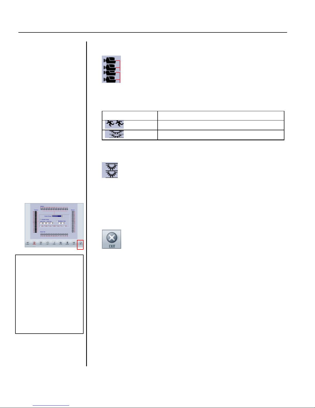
4. Activate the camera
Click the camera icon to activate the camera (s) which will be used in this group.
5. Select the Recording mode
Select the recording mode for each channel. There are three recording modes.
DEFAULT Continuous recording
Motion
Sensor
Record while motion detected
Record while Sensor is active
6. Setup Alarm Out: Alarm Output may be setup when either a sensor is triggered
or motion is detected.
7. Set up another group
Repeat the step from 1 to 6 if you want to set up another group.
8. Exit
You may click any other icon to exit Schedule Setup Mode and go directly
into other setup mode. Click EXIT button to go back to Watch Mode.
setup and exit to the LIVE
mode, the system will
spend about 20 second to
compensate and install
the new setting. This
operation may cause the
image of the cameras
stop motion or
discontinuous motion.
The recorded data also
have the same effect.
Page 19
TATUNG TDR series Digital Recording System Page 15
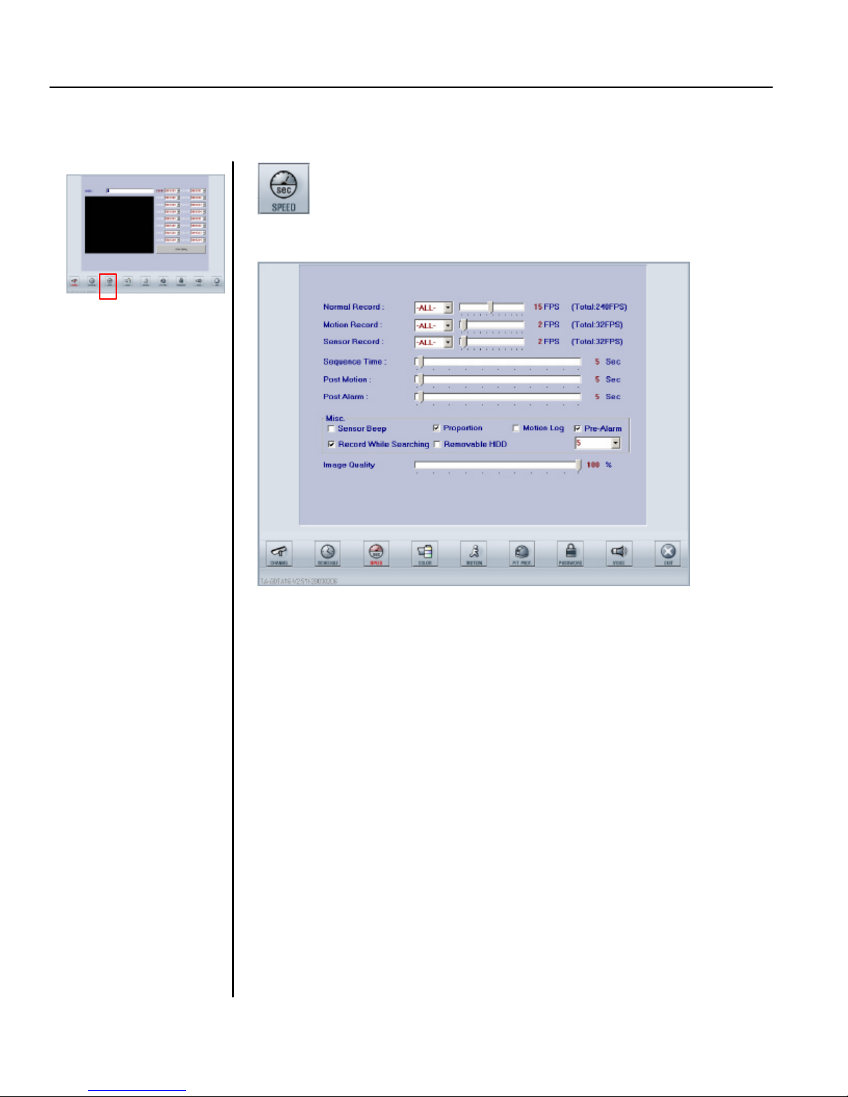
3.3 Speed
This function button (as shown below) can be used to setup the recording speeds.
Click this button and the screen will display as shown below.
Normal Recording Speed
Dragging the cursor can designate normal recording speed (frame rate) for each
camera or all cameras (Separate frame rate for each camera is available).
Motion Recording Speed
Dragging the cursor can designate motion recording speed (frame rate) for each
camera or all cameras (Separate frame rate for each camera is available).
Sensor Recording Speed
Dragging the cursor can designate sensor recording speed (frame rate) for each
camera or all cameras (Separate frame rate for each camera is available).
Sequential Time
Adjust the dwell time interval for sequential display.
Post Motion Time
Keeps recording for a period of time after motion detection is over.
Post Alarm Time
Keeps recording for a period of time after sensor alarm is finished.
Page 20
TATUNG TDR series Digital Recording System Page 16
Note:
When complete the
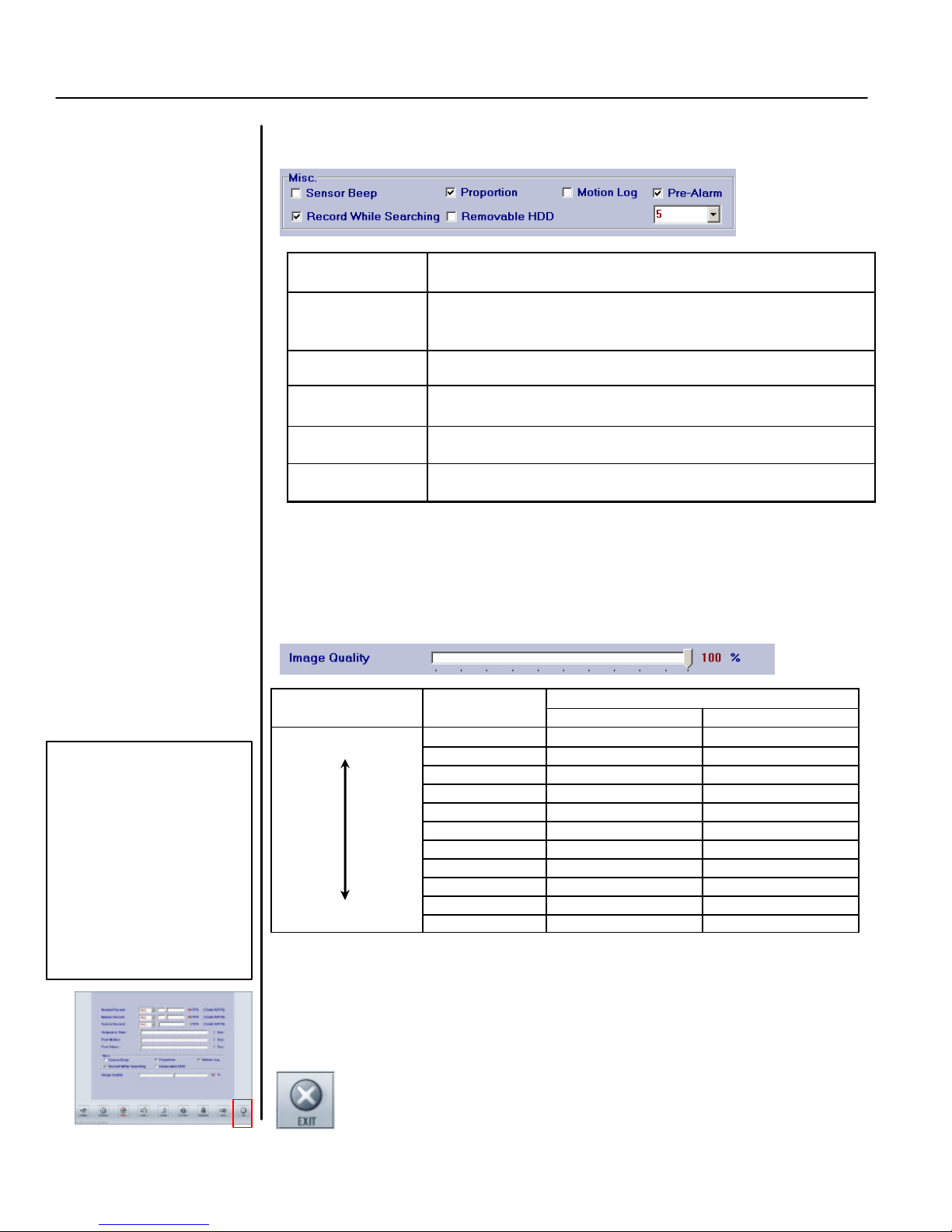
MISC
Check on the box if you want the following features to be enabled.
Sensor Beep Activates beeping sound when sensor is triggered.
Proportion
When activated, only 1, 4, 9, & 16 divisions are available to
keep the horizontal and vertical ratio of each channel window.
Motion Log Activates Motion log function.
Recording While
Searching
Continues to record when the system in search mode.
Removable HDD System Will BEEP when the removable HDD is almost full.
Pre-Alarm Set up PRE -ALARM and PRE-MOTION in SECONDS
Image Quality
Dragging the cursor can adjust the compression rate, the higher the compression the
worse the image quality. The recorded image with best quality (100%) is clear and
vivid. But the size of a frame is the largest (15KB-20KB). At lower percentage of
quality (higher compression rate) image quality is relatively low. But the size of a
frame is relatively small (2KB-8KB). 34% -50% of image quality is recommended.
Compression Rate Image Quality
HIGH
setup and exit to the LIVE
mode, the system will
spend about 20 sec ond to
compensate and install
the new setting. This
operation may cause the
image of the cameras
stop motion or
discontinuous motion.
The recorded data also
have the same effect.
*Frame size may vary from image to image according to the situation of site
LOW
10%
20%
30%
40%
50%
60%
70%
80%
90%
100%
Frame Size**
Range Average
0% 2400-7200 byte
2600-8100 byte
2900-9300 byte
3500-10300 byte
4100-12000 byte
5000-14000 byte
6000-16000 byte
6600-17000 byte
8200-20000 byte
9200-22000 byte
14000-24000 byte
5.0 KB
5.5KB
6.0 KB
7.0 KB
8.0 KB
9.5 KB
11.0 KB
12.0 KB
14.0 KB
16.0 KB
19.0 KB
EXIT
You may click any other icon to exit Speed Setup Mode and go directly into other
setup mode. Click EXIT button to go back to Watch Mode.
Page 21

TATUNG TDR series Digital Recording System Page 17
Bright:
Adjust the brightness.
Note:
When complete the
3.4 Color
This function button (as shown below) is used to setup the colors.
Click this button to setup the color, the screen will be shown as below.
1. Select channel
Select the channel (from 1 to 16) you want to adjust.
setup and exit to the LIVE
mode, the system will
Drag the cursor to adjust the followings for each channel.
spend about 20 second to
compensate and install
the new setting. This
operation may cause the
image of the cameras
stop motion or
discontinuous motion.
The recorded data also
have the same effect.
2. Adjust the Color
Const: Adjust the contrast.
Color: Adjust the color saturation.
Tint: Adjust the tint.
Default color: Load default color value.
3. EXIT
You may click any other icon to exit Color Setup Mode and go directly
into other setup mode. Click EXIT button to go back to Watch Mode.
Page 22

TATUNG TDR series Digital Recording System Page 18
Click on this button to setup the motion, the screen display as the below
Note:
If no detection zone
is
Note:
After the camera is
3.5 Motion
This function button (as shown below) can be used to setup the motions.
Select a channel (from 1 to 16).
defined, the system will
recognize the whole windows
as the detection zone.
motion activated in Schedule
Motion beep
Setup Mode and after the
In motion recording mode, BEEP sound (if the speaker was included in the
detect zone is set, this
channel will be motion-
system) can be activated/de activated by checking the box or not. Beep time can
activated in the defined area.
be also be adjusted by dragging the cursor accordingly.
If anything falls in this area,
the detected motion will be
seen in a lot of small blue
squares. And red wording
“MOTION DETECTION” will
be blinking.
(Please following the 4 steps)
1. Select channel
2. Set up motion detection zone.
Setup the motion detection zone for each channel by clicking and draging. It will
be designated by a red square (Maximum 10 areas per camera).
3. Set up the MISC options.
Page 23

TATUNG TDR series Digital Recording System Page 19
Note:
When complete the
Sensitivity
Set the sensitivity of software motion detection. At highest sensitivity even very
trivial motion will be detected.
Clear all block
Clear all of the detecting zones for a specific channel.
4. EXIT
You may click any other icon to exit Motion Setup Mode and go directly
into other setup mode. Click EXIT button to go back to Watch Mode.
setup and exit to the LIVE
mode, the system will
spend about 20 second to
compensate and install
the new setting. This
operation may cause the
image of the cameras
stop motion or
discontinuous motion.
The recorded data also
have the same effect.
Page 24

TATUNG TDR series Digital Recording System Page 20
Click on this button to setup the P/T/Z Protocol, the screen displa
y as the
Click to choose a
Click to assign
a
Choose the number
Note:
When complete the
3.6 P/T/Z Protocol
This function button (as shown below) is used to setup P/T/Z Protocol.
Please select the same protocol as that of your camera.
You may click any other icon to exit Protocol Setup Mode and go directly into
setup and exit to the LIVE
mode, the system will
spend about 20 second to
compensate and install
the new setting. This
operation may cause the
image of the cameras
stop motion or
discontinuous motion.
The recorded data also
have the same effect.
other setup mode. Click EXIT button to go back to Watch Mode.
below
here to control the
camera address
more than 16
EXIT
manufacturer
brand from a
drop-down list
communication
port.
Page 25

TATUNG TDR series Digital Recording System Page 21
Note:
See next page for the
1.
Select the password
level
.
Note
: For TDR
-
2209, the Hide
3.7 Password
This function button (as shown below) can be used to setup the password.
Click on this button to setup the Password.
Camera function CH 10 to CH 16
will be useless even you activate
it. For TDR-2204, the Hide
Camera function CH 05 to CH 16
will be useless even you activate
it.
remote access password.
• Password
There are five levels of passwords for security purposes.
(Please follow the steps below)
2. Key in the new password. (From keyboard, mouse, or touch screen).
3. Click on “Apply” when finished or “Clear” to canceled
Page 26

TATUNG TDR series Digital Recording System Page 22
NOTE:
To set up the Remote
Sign up
• Remote username/password
Select the Remote Access in the Password Select window. An Input
Password window will be prompted up. After entering the password and
click OK, the following screen will be shown. Here the TATUNG TDR series
allows the administrator to sign up remote users.
username/password. The
system will ask the SETUP
password again to confirm
the authority of the user
§
o Click “Sign up” button will prompt the Register Account window.
o Key in the New ID and Password.
o Then click Entry button.
o Click “Exit” button to leave above window.
§ Delete
o Click on the user’s name in the Registered ID window above.
o Click on “Delete ” button.
o Click “Exit” button to leave above window.
§ Edit User
o Click on user’s name in the Registered ID window above. The
user’s ID and Password will be shown in the “User information”
and “Select Hide camera ” window.
o If you want to change the password, click the “Change Password”
button. After entering the new password, you have to confirm it.
Then click APPLY and OK in Account window to complete.
o If you want to hide the cameras for this user, check the box for
each camera or click on the button of either “Select All Camera ” or
“Clear All Camera”.
o Click “Exit” button to leave above window.
Page 27

TATUNG TDR series Digital Recording System Page 23
Note
: For TDR
-
2209, the Hide
Note:
When complete the
have the same effect.
• Hide Cameras
Check the box(es) to hide the specific channel(s) of the server site.
Camera function of Remote
Client CH 10 to CH 16 will be
useless even if you activate it.
For TDR-2204, the Hide Camera
function of Remote Client CH 05
to CH 16 will be useless even if
you activate it.
• Restart Window
Check the box of the day and assign the time to restart the system.
EXIT
You may click any other icon to exit Password Setup Mode and go directly into
other setup mode. Click EXIT button to go back to Watch Mode.
setup and exit to the LIVE
mode, the system will
spend about 20 second to
compensate and install
the new setting. This
operation may cause the
image of the cameras
stop motion or
discontinuous motion.
The recorded data also
Page 28
TATUNG TDR series Digital Recording System Page 24
Click on this button to setup the voice, the screen will
display as shown below
Note:
To have
better voice
Audio
Note:
When complete the
3.8 Voice
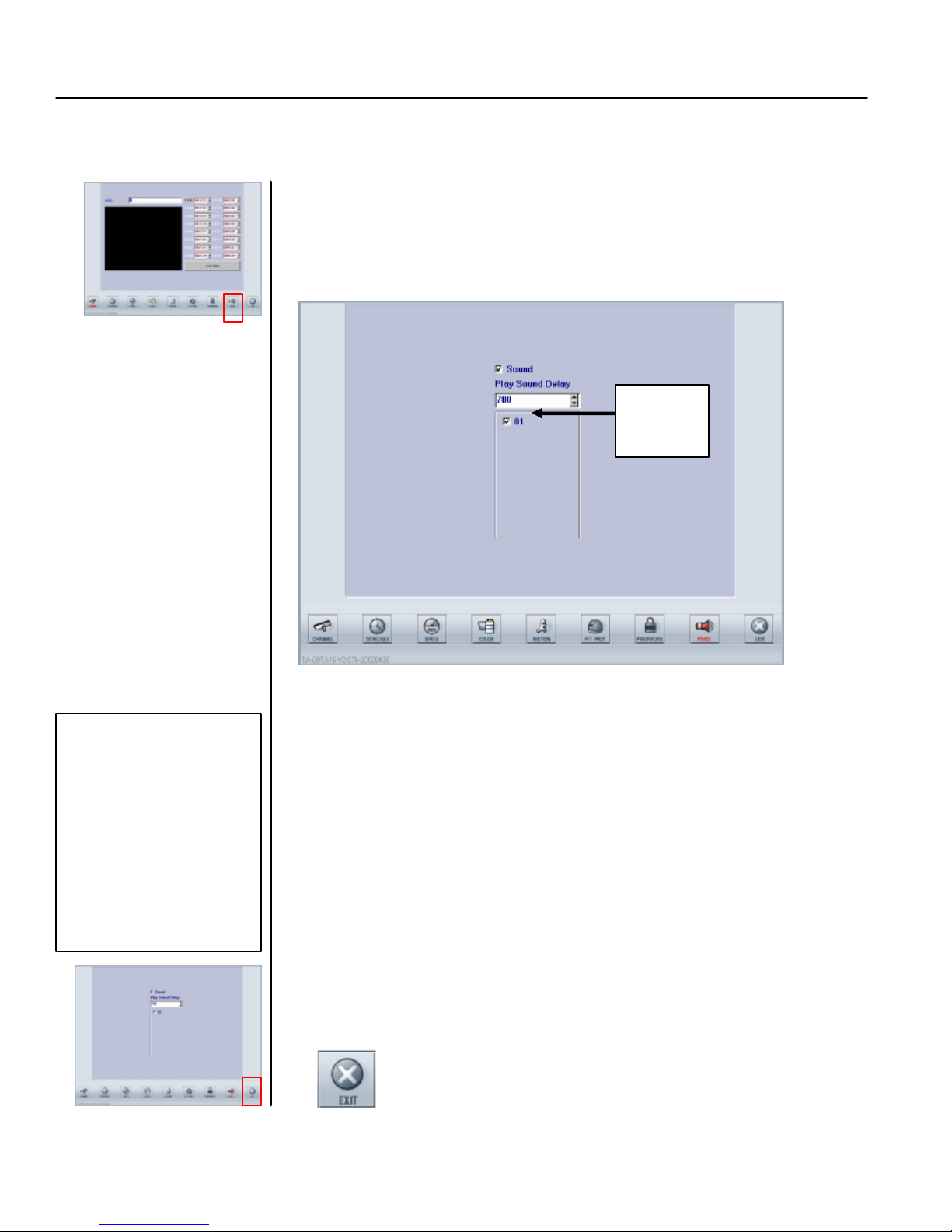
This function button (as shown below) is used to setup the voice settings.
(Please follow the steps)
Channel
one
playback quality, the image
recording speed should be set
to more than 2 FPS.
1. Check the box of “sound”
Check on this box to enable the sound recording.
setup and exit to the LIVE
mode, the system will
spend about 20 second to
Adjust this number to coordinate the synchronizati on of sound playback and
compensate and install
video playback. The number 700 means the system coordinates the
the new setting. This
synchronization every 700 seconds. The faster the image recording speed, the
operation may cause the
smaller the delay time should be chosen. This means the two playbacks need
image of the cameras
to be coordinated more frequently. However, if the image recording speed is
stop motion or
slow, we may choose longer time (large number) to coordinate the two
discontinuous motion.
playbacks.
The recorded data also
have the same effect.
For TDR-22XX series, audio can only be recorded on channel one (01).
2. Adjust the “Play Sound Delay”
3. Check on the box of the channel you want to activate
4. EXIT
You may click any other icon to exit Voice Setup Mode and go directly into other
setup mode. Or click EXIT button to go back to Watch Mode.
Page 29

TATUNG TDR series Digital Recording System Page 25
Note:
You can always click on
3.9 Exit
Click on EXIT button to switch back to WATCH MODE after you complete all the settings in the
SETUP mode.
the EXIT to switch back to
watch mode no matter what
function mode you are in.
When complete the setup and exit to the LIVE mode, the system will
spend about 20 second to compensate and install the new setting.
This operation may cause the image of the cameras stop motion or
discontinuous motion. The recorded data also have the same effect.
Page 30

TATUNG TDR series Digital Recording System Page 26
CHAPTER 4: SEARCH
MODE
The buttons and icon
s of the main
search
screen are described below:
like
recording capacity.
Note
: For TDR
-
2209 there are
The main screen of the search mode is shown below.
only 9 channels divided within
the screen. For TDR-2204
there are only 4 channels
divided within the screen
1. Date/Time
Click on this button to search the images by Date and Time. A calendardata selection window including From-Time and To -Time will be prompted
up.
2. Log
Click this button to check the sensor recording log and motion recording
log of the system. You can also search for images from these logs.
3. Save Disk
Click this button to save a short period of images to a floppy disk. An
image’s channels and frames are selectable in this function.
4. Print
Click to print a specific image on the system printer for immediate data
retrieval. An image’s channels and frames are selectable in this function no
matter if the printer is a local printer or a network printer.
5. Storage Capacity
Click to check the usage information of the data storage (removable HDD).
The information includes both the sound recording capacity and the image
Page 31

TATUNG TDR series Digital Recording System Page 27
6.
Scroll Bar
Drag the cursor to search for images within a 24-hour period of a selected
date. The cursor’s corresponding time is displayed to the right.
7. Buttons on Play Back Console
These control buttons are used to playback the data, Which includes the
start of the record, 1 previous minute, 1 previous frame, playback, quick
play, stop, 1 next frame, 1 next minute and the end of the record.
8. Exit
Click this button to exit the Search Mode and back to the Watch Mode.
9. Channel playback window
This is the area to display the playback images along with the channel
names and the recording date and time. All channels can be played back
synchronously.
Page 32

TATUNG TDR series Digital Recording System Page 28
Channel
Note:
You can always enlarge a
Note
: For TDR
-
2209 there are
1.
Set up motion detection zone
(s).
4.1 Channel play back window
This area is the 16 channel play -back window. All channels can be played back synchronously.
• Display one specific channel only:
You can always left click a specific channel to highlight this specific channel
in the middle of the window and enlarge it. By left clicking again you can go
back to the multi channel play back.
only 9 channels divided within
the screen. For TDR-2204 there
are only 4 channels divided
within the screen
specific channel by left clicking
on the channel. You can also
left click again to back to the
multi-channel playback mode.
• Mute, night vision, and digital zoom.
• Object Search
Name
1. Mute
Mute the audio of this channel by checking the mute box.
2. Night Vision
Check the night vision box to enhance the brightness of the picture.
3. Digital Zoom
Check the digital zoom box and us e right-click and left-click to enlarge or
shrink the image. This function is only available when playback is
stopped
This feature is used to search a specific area on a camera for motion. To
access this function you must be in search mode and select the specific
camera you want to perform an object search on.
Click on this button to activate the object view mode.
Setup the motion detection zone for each channel by clicking and
Press MODE again to exit Object Search Mode and clear the search
dragging. It will be designated by a red square (Maximum 10 areas).
2. Set up OPTIONS (please see the left picture)
Adjust Sensitivity and whether you want to view the image while
searching or not. Then click OK
3. Begin search
Click START to begin search. Once motion is detected the search will
stop and alert you of the detection. To continue searching for the next
occurrence of motion click START again to begin the search again.
4. STOP search
Click STOP to stop the search.
5. Return to previous detected occurrence
Click BACK to return to the previous occurrence of motion detected.
6. Exit Object Search Mode and Clear blocks
Page 33

TATUNG TDR series Digital Recording System Page 29
Beginning of
1 frame
Quick
1 frame
End of the
1 min
1 min
Note:
You can always playback
4.2 Buttons on Play Back Console
These buttons are used to control the data stream.
the images whether you are in
the multi-channel playback mode
or in one specific channel
playback mode.
back
Stop Play
forward
the record
back
play
forward
Record
• START : From the very beginning of the recorded images.
• PREV 1 MIN : BACKWARD one minute from the current playback time.
• PREV FRAME : BACK one frame from the current playback time.
• PLAY : PLAYBACK the images with normal speed.
• QUICK PLAY : PLAYBACK with faster speed.
• STOP : STOP the playback.
• NEXT FRAME : FORWARD one frame from the current playback time.
• NEXT 1 MIN : FORWARD one minute from the current playback time.
• END : To the end of the recorded images.
Page 34

TATUNG TDR series Digital Recording System Page 30
Date selection:
From
-
Time se
lection:
To-Time selection:
Start:
window will disappear)
EXIT:
Click this button and
the screen
will prompt out a calendar like
the
data
Note:
You can always select the
4.3 Date/Time
This function button is used to search the images by date and time.
date/time whether you are in the
multi channel playback mode or
one specific channel playback
mode.
selection window displayed below. You may search the images recorded on
the selected date and time. (Please follow the steps below)
Please click on the date with a
red mark to select
Key in the From -Time may also accomplish
by clicking on the arrows or drag scroll bar.
Key in the To-Time may also accomplish by
clicking on the arrows or drag the scroll bar.
Click on this button to start the
searching. (The whole selection
Click on this button to exit (The whole selection window will disappear)
1. Date selection
Select the date you want to search by clicking the red check mark . If this is
not the correct month, use the arrow to choose the month you
want.
2. From-Time Selection
There are three ways to enter the search starting time or From -Time: Use the
keyboard to enter, click the little arrows, or drag the scroll bar.
3. To-Time Selection
Search ending time or To-Time can also be entered by keying the numbers into
the Hour and Minute blocks, clicking the arrows, or drag the scroll bar.
Page 35

TATUNG TDR series Digital Recording System Page 31
4. Start
After completing the date and time selection, click on the “Start” button to
search or playback the recorded images (after clicking, the date/time selection
window will disappear).
5. EXIT
If you want to cancel this date and time selection, click “EXIT” to back to the
main screen of the search mode. (The whole date/time selection window will
disappear).
Page 36

TATUNG TDR series Digital Recording System Page 32
Click
here to review the
Click here to review
Select the Log
Date
Time
Close Log
Click this button the screen will prompt out a data list displayed as below.
Next Page when
Previous Page when
4.4 Log
Function button can be used to search the images from motion recording and sensor recording logs.
(Please follow the steps below)
Sensor Recording Log
the Motion
Recording Log
and click here to
playback the data
selection
selection
Search function
Item List
the list is more than
1000 events
the list is more
than 1000 events
1. Sensor Recording Log or Motion Recording Log
Select the log database you want to search.
2. Date
Select the date you want to search.
3. Time
Select the time you want to search.
4. List item
Click on a specific item you want to view.
5. Playback or Close
Click “Play Back” button to review the image you searched, or Close the
function.
Page 37

TATUNG TDR series Digital Recording System Page 33
Number of frames wanted to save for
Channel
Click on this button the screen will prompt out a save disk window as below
4.5 Save Disk
This function button is used to save pictures or a short period of images to a floppy disk. Channels
and number of frames are selectable in this function.
(Please follow the steps below)
all or selected channels.
Image type
selection
1. Please make sure you insert a floppy diskette.
2. Channel selection
Select either all channel or one specific channel to save.
3. Cut
Assign the number of frames you want to save for all channels.
4. Image type
Select the image type (JPG or BMP)
5 OK or NO
Click “OK” button to save or “NO” to cancel.
Page 38

TATUNG TDR series Digital Recording System Page 34
Click on this button to print the specifi
c image to floppy disk as
Title that will be printed on the paper.
Number of frame
s
wanted to print for all
Channel
Setup the
4.6 Print
This function is to print the specific image on the system printer as an immediate data retrieval.
Channels and frames are selectable in this function.
immediate data retrieval. The screen will prompt out a print window as
shown below (Please follow the steps)
or selected channels.
selection
PRINTER
1. Please make sure that a system printer has been installed.
2. Channel selection
Select either all channel or one specific channel to retrieve.
3. Cut Print
Assign the number of frames you want to print for all channels.
4. Print or Cancel
Click “Print” button to print or “Cancel” to cancel the print job.
Page 39

TATUNG TDR series Digital Recording System Page 35
Click on this button to prompt out the window for storage information as
Note:
If the sound recording
Click on this button to leave the Search Mode and
go
back to the Watch
4.7 Storage Capacity
This function is used to check the usage information of the removable HDD.
function is disabled, the sound
storage space reserved will be
constituted as part of the total
storage capacity.
4.9 EXIT
shown below.
Mode.
Page 40

TATUNG TDR series Digital Recording System Page 36
CHAPTER 5: BACKUP MODE
AVI file immediate
Cancel Back
up
Note:
In this mode, the
Note:
In this mode, if you
After clicking the Backup button, the following window is prompted out.
system is still recording no
matter what you do in this
mode that is why you can still
see the system program
running in the background
Auto backup Function
want to backup or save the
data into the CD-RW DRIVE,
you must have a CD-RW disk
insert into the drive and have
it formatted with the DIREC
CD compatible process.
operation
• Auto backup
Automatically backup the recorded images with a customized time schedule.
• AVI Backup
Immediately backup the recorded images in AVI format.
• Explorer
Open Windows Explorer and let the operator configure the system.
• Cancel
Leave the Backup Mode and go back to the Watch Mode.
backup
Windows explorer
Page 41

TATUNG TDR series Digital Recording System Page 37
Note:
The scheduled backup
Note:
You can also search the
5.1 Auto Backup
This function is used to back up the recorded images from a customized time schedule. The
execution time of the backup can also be assigned. The screen will prompt out the following
window after clicking on the Auto Backup button. (Please follow the steps below)
• Daily Backup
Select the Daily Backup panel if you want to enable the daily backup function
function is to backup the
previous day’s data. If you
check the ‘Day of backup’
box for Sunday, the system
will backup the data recorded
on Saturday at the execution
time on Sunday.
data from a list by clicking on
the “File Information“ button.
1. Check the Enable Box and select the backup Period
2. Check the box of the days to backup (Sunday to Saturday)
3. Assign the execution time and the backup device
4. Click Apply button and then EXIT
Page 42
TATUNG TDR series Digital Recording System Page 38
Note:
You can also search the
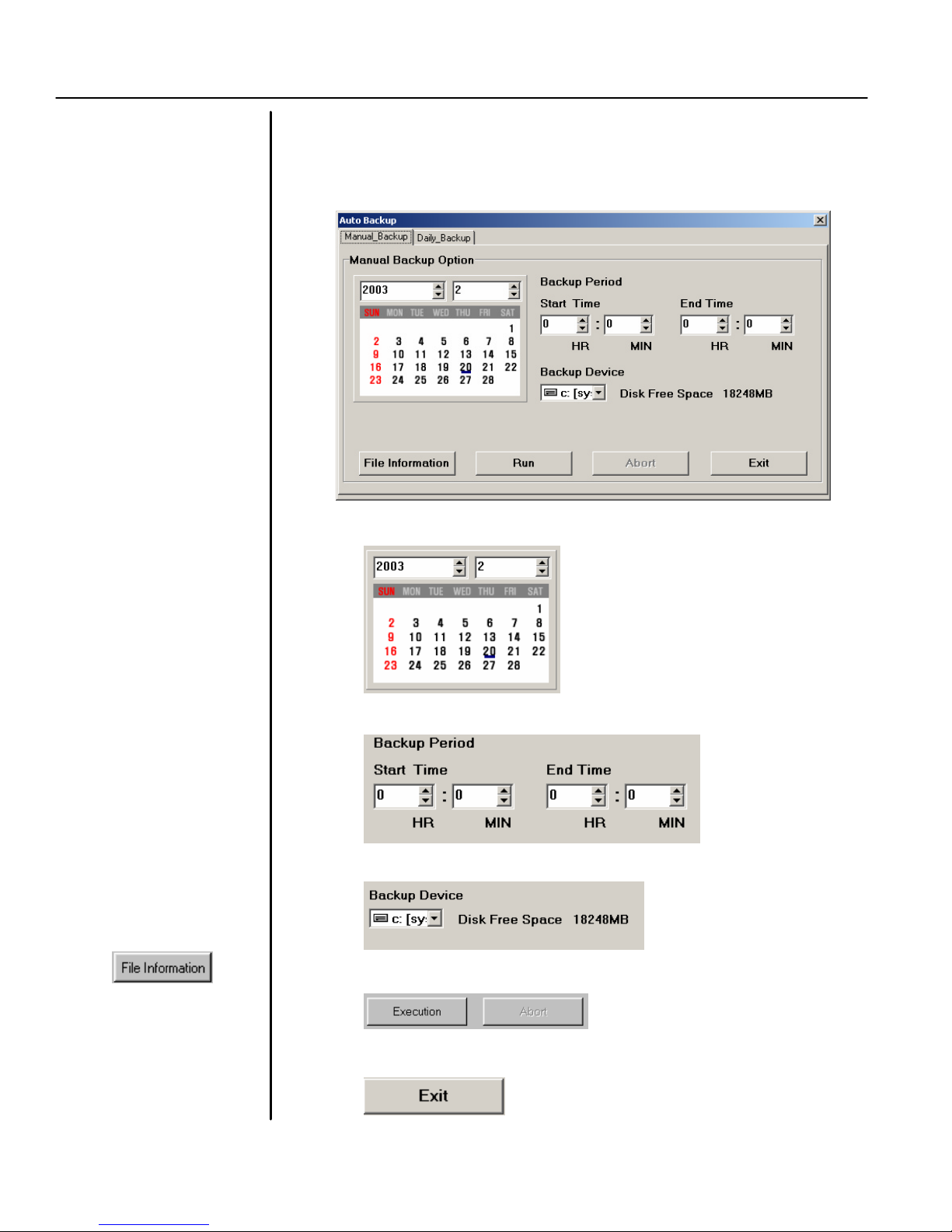
• Manual backup
If you want to immediately backup some images, select the manual backup
panel and follow the steps below.
1. Assign the backup date from the calendar
2. Assign the starting time and ending time you want to backup
data from a list by clicking on
the “File Information“ button.
Leave the Auto Backup Mode and go back to the Watch Mode
3. Select the backup device
4. Execute the back up or Abort during the back up process.
5. Exit
Page 43

TATUNG TDR series Digital Recording System Page 39
Note:
You can also search the
Note:
AVI BACUP function will
5.2 AVI Backup
This functio n is to back up the selected data immediately to an AVI file (Windows default audio and
video in formation file). The screen will prompt out the windows as shown below after clicking on this
button. (Please follow these steps).
data from the list by clicking on
the “File Information “button.
eject the CD after the whole
process is completed for user’s
convenience
1. Camera
Select the camera (cha nnel) to backup
2. Backup Date
Assign the date of the data you want to backup
3. Date Start Time
Assign the Start time of the data you want to backup
4. Date End Time
Assign the End time of the data you want to backup
5. File Name
Click on here to assign a file name and choose the device for this backup
6. Insert Watermark or not
Insert the watermark for data verification.
7. Start/Stop/Close
Start the backup or stop the backup or close this function and go back to
watch mode.
Page 44

TATUNG TDR series Digital Recording System Page 40
5.3 Explorer
This function is to call out the WINDOWS EXPLORER which let the operator control this system.
The screen will prompt out the Windows explorer as shown below.
5.4 Cancel
Cancel this function mode and go back to watch mode.
Page 45

TATUNG TDR series Digital Recording System Page 41
CHAPTER 6: CONTROL MODE
Camera
P/T control
ZOOM/FOCUS/PRESET
Note
: For
the
TDR-2209 there
Speed up
camera
The main screen of the control mode is shown by the following picture
are only 9 channels divided
within the screen. For the TDR2204 there are only 4 channels
divided within the screen
selection panel
the
panel
Control buttons
6.1 Camera Control
Control PTZ camera
Camera Selection Panel :
Select the camera you want to control
(The camera number will turn RED when activated)
• PAN/TILT CONTROL Panel:
Pan/Tilt and Autopan control for the camera
Page 46

TATUNG TDR series Digital Recording System Page 42
ZOOM/FOCUS c
ontrol
Load or select the
Note: BS stand for back space,
CLR is CLEAR
• PT Acceleration
Check the BOX to accelerate the PTZ movement.
• ZOOM/FOCUS/PRESET Buttons:
. Zoom/Focus/Preset Buttons
default setting for a
selected camera
CLR stand for clear
• PRESET Function:
i. Set presets
1. Adjust the camera to its desired preset location.
2. Assign the preset number locations by clicking or typing into
the box.
3. Click on “SET” to confirm the position.
4. Repeat from 1 to 3 until you setup all the position you want
and click “EXIT”.
ii. Access presets
1. Assign the preset number locations by clicking or typing into
the box.
2. Click on “GO” to confirm the position or “STOP” to abort
this command during the camera is turning.
BS is Backspace
6.2 EXIT
Click on this button to exit the control mode and go back to the Watch mode.
Page 47

TATUNG TDR series Digital Recording System Page 43
APPENDIX A:
Alarm
Connector Configuration
Alarm in
Ground
Alarm out
Alarm out
Alarm in
Ground
amera In/Out
• Alarm In/Out: 16 ALARM IN and 8 ALARM OUT (NC and NO)
(TDR-2216, TDR-2209)
(Sensor)
(Common)
S 1 S 2 S 3 S 4 S 5 S 6 S 7 S 8 S 9 S
NC 1 CM 1 NO 1 NC 2 CM 2 NO 2 NC 3 CM 3 NO 3 NC 4 CM 4 NO 4 NC 5 CM 5 NO 5 NC 6 CM 6 NO 6 NC 7 CM 7 NO 7 NC 8 CM 8 NO
10 S 11 S 12 S 13 S 14 S 15 S 16
(NC or NO)
G G G G G G G G
• Alarm In/Out: 8 ALARM IN and 4 ALARM OUT (NC and NO)
(TDR-2204)
(Sensor)
(Common)
8
S 1 S 2 S 3 S 4 S 5 S 6 S 7 S
NC 1 CM 1 NO 1 NC 2 CM 2 NO 2 NC 3 CM 3 NO 3 NC 4 CM 4 NO
(NC or NO)
G G G G G G G G
8
4
Page 48

TATUNG TDR series Digital Recording System Page 44
Page 49

TATUNG TDR series Digital Recording System Page 45
APPENDIX
B: AVI PLAYER Instruction
AVI player is located in your Application CD which is used for watermark verification and play back of the AVI clips you
saved.
1. SOFTWARE INSTALLATION
a. Inset the Application CD into CDRW or DVD-RAM
b. Click on My Computer and Open the CDRW or DVD-RAM.
c. Find the AVI PLAYER FOLDER AND GO INTO THIS FOLDER. Double Click on “SETUP.EXE” and
the screen will be shown as below.
d. To install to the directory of “C:\TATUNGAVIPLAYER”, go to step “e”. To install to a different
directory, click Browse button and select another directory till the correct directory appear in the
destination directory. The screen will show as the below.
e. Click on Next button when ready. The screen will show as below.
Page 50

TATUNG TDR series Digital Recording System Page 46
f. Check the information to see if they are correct and then click on Next button. The system will begin
the installation and then screen will show as below.
g. Click on Finish
2. SOFTWARE EXECUTION
a. Double click on the icon below. The program will be executed and a window will show as below
b. Click on File Open button to choose the AVI clip you want to verify.
Page 51

TATUNG TDR series Digital Recording System Page 47
c. After selected, click on open and back to the AVI player program. Click on the WATERMARK button
to switch the verification function if you want to check the watermark or not.
d. Click on PLAY or PAUSE when ready to play or you want to stop and to see the details.
e. Click on the EXIT button to exit the program or just click on the File Open to select another AVI clip.
Page 52

TATUNG TDR series Digital Recording System Page 48
Page 53

TATUNG TDR series Digital Recording System Page 49
APPENDIX
C: BACKUP VIEWER Instruction
BACKUP VIEWER is located in your Application CD which is used for viewing the backup data you saved.
1. SOFTWARE INSTALLATION
a. Inset the Application CD into CDRW or DVD-RAM
b. Click on My Computer and Open the CDRW or DVD-RAM.
c. Find the VIEWER FOLDER AND GO INTO THIS FOLDER. Double Click on “SETUP.EXE” and the
screen will be shown as below.
d. To install to the directory of “C:\Program File\Tatung TDR Series Viewer”, go to step “e”. To install
to a different directory, click Browse button and select another directory till the correct directory
appear in the destination directory. The screen will show as the below.
e. Click on Next button when ready. The screen will show as below.
Page 54

TATUNG TDR series Digital Recording System Page 50
f. Check the information to see if they are correct and then click on Next button. The system will begin
the installation and then screen will show as below.
g. Click on Finish
2. SOFTWARE EXECUTION
From windows start up menu, click Programs, click TATUNGVIEWER, then the program will be ex ecuted
and shows as below
Page 55

TATUNG TDR series Digital Recording System Page 51
Beginning of
1 frame
Quick
1 frame
End of the
1 min
1 min
• Playback Console
back
Stop Play
forward
the record
back
play
forward
Record
• START : From the very beginning of the recorded images.
• PREV 1 MIN : BACKWARD one minute from the current playback time.
• PREV FRAME : BACK one frame from the current playback time.
• PLAY : PLAYBACK the images with normal speed.
• QUICK PLAY : PLAYBACK with faster speed.
• STOP : STOP the playback.
• NEXT FRAME : FORWARD one frame from the current playback time.
• NEXT 1 MIN : FORWARD one minute from the current play back time.
• END : To the end of the recorded images.
• FOLDER Button
Click on this button to choose the backup data folder.
Page 56

TATUNG TDR series Digital Recording System Page 52
Date selection:
Camera selection
:
Brightness adjustment:
Contrast adjustment:
Number of frames wanted to save for
Channel
Click on this button the screen will prompt out a save disk windo
w as below
• Date and Time selection
This function button is used to search the images by date and time.
Please click on the date with a
red mark to select.
Choose the channel you want to view.
Click on this button and the arrow
button to adjust the brightness.
Click on this button and the arrow button to adjust the contrast.
• Search
Select the time off the day you want to view.
• Save Disk
This function button is used to save pictures or a short period of images to a floppy disk. Channels
and number of frames are selectable in this function.
(Please follow the steps below)
all or selected channels.
selection
Image type
1. Please make su re you insert a floppy diskette.
2. Channel selection
Select either all channel or one specific channel to save.
3. Cut
Assign the number of frames you want to save for all channels.
4. Image type
Select the image type (JPG or BMP)
5 OK or NO
Click “OK” button to save or “NO” to cancel.
Page 57

TATUNG TDR series Digital Recording System Page 53
Click on this button to print the specific image to floppy disk as
Title that will be printed on the paper.
Number of frame
s
wanted to print for all
Channel
Setup the
• Print
This function is to print the specific image on the system printer as an immediate data retrieval.
Channels and frames are selectable in this function.
immediate data retrieval. The screen will prompt out a print window as
shown below (Please follow the steps)
or selected channels.
selection
PRINTER
1. Please make sure that a system printer has been installed.
2. Channel selection
Select either all channel or one specific channel to retrieve.
3. Cut Print
Assign the number of frames you want to print for all channels.
4. Print or Cancel
Click “Print” button to print or “Cancel” to cancel the print job.
Page 58

TATUNG TDR series Digital Recording System Page 54
Page 59

TATUNG TDR series Digital Recording System Page 55
S
OFTWARE:
MODELS
TDR-22xx
Series image size
APPENDIX D: Technical Specification
Operation System Windows 98 SE/Windows 2000/ Windows XP
Display Speed Real-time
TDR -2216 480FPS
TDR -2209 270FPS
TDR -2204 120FPS
Record Speed
TDR -2216 240FPS MAX
TDR -2209 240FPS MAX
TDR -2204 120FPS MAX
GENERAL
Operation Temperature 41° to 104°F (5° to 40°C).
Relative Humidity Maximum 80% non- condensing
Dimensions 7” H x 17” W x 18” D
(17.78 x 43.18 x 45.72 cm)
Weight (Approximate) 46.2 lb (20.96 kg) unit
58.3 lb (26.24 kg) ship
ELECTRICAL:
Power Voltage 100-240 VAC Switchable, 50/60 Hz
Signal System NTSC/PAL
System Spec
TDR -2216 PIV 1.6GHZ, 256 MB
TDR -2209 PIII 866 MHz, 256 MB
TDR -2204 PIII 733 MHz, 256 MB
Image Resolution 320 x 240
Compression M -JPEG
Image Size 2K ~ 20K
Video Inputs
TDR -2216 16 CH
TDR -2209 9 CH
TDR -2204 4 CH
Video Outputs 2 (1 XGA, 1 Composite)
Alarm Inputs
TDR -2216 16
TDR -2209 16
TDR -2204 8(NC&NO)
Alarm Outputs
TDR -2216 8
TDR -2209 8
TDR -2204 4(NC&NO)
Remote Control PSTN, ISDN, TCP/IP
Pan/Tilt/Zoom RS-232 (to RS-485 with converter)
Supplied accessories: PS/2 Keyboard with mouse, Software
protection socket, Power cable, Windows® 98 SE, Windows 2000
(option), Remote site software, Backup viewer, AVI player and rack
mount ears.
Minimum Requirements for remote site PC:
Pentium II 400 MHz , 64 MB Memory, 4 GB HDD, 8MB AGP Video Card,
10 MBPS LAN, 28800 MODEM (PSTN mode), MS-Windows 98 / 98SE /
ME / NT 4.0 / 2000 /XP
HDD 16 CH 9 CH 4 CH
40 GB TDR -2216-040 TDR-2209-040 TDR-2204-040
80 GB TDR -2216-080 TDR-2209-080 TDR-2204-080
120 GB TDR -2216-120 TDR-2209-120 TDR-2204-120
160 GB TDR -2216-160 TDR-2209-160 TDR-2204-160
320 GB TDR -2216-320 TDR-2209-320 TDR-2204-320
400 GB TDR -2216-400 TDR-2209-400 TDR-2204-400
500 GB TDR -2216-500 TDR-2209-500 TDR-2204-500
OPTIONAL DEVICE
DVD-RAM DRIVE DVD-RAM drive, backup the data to (4.7
GB/9.8 GB) or (2.6 GB/5.4GB) disk,
writes up to 1.38MB/second and reads
up to 2.77MB/second.
ANALOG MODEM 56K external modem Full-on 2-wire phone
lines
RACK MOUNT VT19726DVR 19” Rack mountable CRT
MONITOR monitor with XGA input.
TOUCH SCREEN 19” Rack mountable touch screen monitor,
MONITOR used for replacing the mouse to meet specific
application requirement.
RACK MOUNT Rack mountable keyboard drawer and
KEYBOARD keyboard with touch pad.
W/TOUCH PAD
CONNECTORS:
BNC Camera inputs and loop through outputs
6-pin Mini DIN PS/2 mouse and keyboard
Push-in Alarm inputs, alarm outputs
9-pin D-type COM 1
15-pin D-type XGA monitor port
25-pin D-type Parallel port
BNC Analog monitor output
RJ-45 TCP/IP, LAN/WAN
SCSI SCSI port for the other SCSI device
Audio in/out Audio recording
CERTIFICATIONS
• FCC
• CE, Class A (TBD)
• UL, CUL (TBD)
Compression Rate HIGH LOW
Image Quality
File Size (KB) 2600 ~ 8100 3500 ~ 10300 5000 ~ 22000
Standard
1% ~
10 %
Good
10% ~ 30%
Best
30% ~ 100%
Page 60

TATUNG TDR series Digital Recording System Page 56
Page 61

TATUNG TDR series Digital Recording System Page 57
APPENDIX
E: Chart
s for recording times
TDR-22xx Series Storage and Recording time
(From RECORD
ING
TIME to Find the Storage Size)
-
-
-
-
- -
-
- - -
-
-
- - -
-
-
1
-
-
- -
- -
- -
- - -
-
- -
- - -
- -
- -
- - -
- - -
-
-
-
- -
- -
- -
- -
- - - -
- -
- -
- - - - - - -
Continuous recording
TDR-
2216
(DAYS)
1 (24hr)
3 (72hr)
7 (168hr)
14 (336hr)
31 (744hr)
100 (2400hr)
365 (8760hr)
TDR-
2209
(DAYS)
3
7
14
31
100
365
15
FPS 7 FPS 3 FPS 1 FPS
250G 120G 80G
730G 400G 160G
-
-
-
-
-
Best Quality Good Quality Standard Quality
27
FPS
250G 160G 80G 40G 40G 160G 120G 80G 40G 40G 120G 80G 40G 40G 40G
730G 400G 200G 40G 40G 500G 320G 160G 80G 40G 400G 200G 120G 40G 40G
15
FPS 7 FPS 3 FPS 1 FPS
-
-
-
-
-
Best Quality Good Quality Standard Quality
400G 120G
730G 320G
15
FPS 7 FPS 3 FPS 1 FPS
40G 160G 80G 40G 40G 120G 80G 40G
80G 500G 250G 120G 40G 400G 200G 80G
- 730G 250G 80G
- - 500G 160G
500G
- -
- -
- -
- 400G
- -
- -
15
FPS 7 FPS 3 FPS 1 FPS
500G 200G
- 400G 120G
- 730G 250G
- -
- -
27
FPS
15
FPS 7 FPS 3 FPS 1 FPS
27
FPS
15
FPS 7 FPS 3 FPS 1 FPS
500G 200G 80G
400G 160G
320G
-
-
730G 320G 160G 80G
730G 250G 120G
730G 200G
- 730G
- -
- 500G 250G 120G 40G
- - 500G 200G 80G
- -
- -
- -
500G 160G
40G
40G
80G
500G
TDR-
2204
(DAYS)
14
31
100
365
Image
30
FPS
1
120G 80G 40G 40G 40G 80G 40G 40G 40G 40G 80G 40G 40G 40G 40G
400G 200G 120G 40G 40G 250G 120G 80G 40G 40G 200G 40G 80G 40G 40G
3
7
TDR-22xx Series Storage size calculation
To select the correct model, you have to select the size of storage for your application. To calculate the storage capacity, please
apply the equation below.
Size
(KB)
5 x
This equation is a generic formula of how TATUNG calculates the storage capaci ty.
Storage calculation is based on the average image size, the actual size may vary.
Contact the customer service for assistance in calculating the capacity for your application.
Best Quality Good Quality Standard Quality
15
FPS 7 FPS 3 FPS 1 FPS
30
FPS
15
FPS 7 FPS 3 FPS
1
FPS
30
FPS
15
FPS 7 FPS 3 FPS
1
FPS
- 500G 250G 120G 40G 730G 320G 160G 80G 40G 500G 250G 120G 80G 40G
-
-
-
-
500G 200G 80G
400G 160G
- 400G
- -
730G 320G 120G 40G
730G 250G 120G
320G
500G 250G 120G 40G
500G 200G 80G
- 730G 200G
- - 730G
Record Speed
x
per Second
1 x
x Channels x
16 x
Records Hours
per DAY
8 x
Record
x
Days
30 x 0.0036 = 69.12
x 0.0036 =
Required Storage
(GB)
Page 62

TATUNG TDR series Digital Recording System Page 58
TDR-22xx Series Storage and Recording time
(From RECORD
ING
TIME to Find the Storage Size)
-
-
- - -
-
1
- -
- -
- -
- - -
-
-
-
-
- -
- - -
- -
Motion or alarm recording which estimated as 15% of continuous recording
TDR-
2216
(DAYS)
1 (24hr)
3 (72hr)
7 (168hr)
14 (336hr)
31 (744hr)
100 (2400hr)
365 (8760hr)
TDR-
2209
(DAYS)
3
7
14
31
100
365
TDR-
2204
(DAYS)
1
3
7
14
31
100
365
TDR-22xx Series Storage size calculation
To select the correct model, you have to select the size of storage for your application. To calculate the storage capacity, please
apply the equation below.
Image
Size
(KB)
5 x
This equation is a generic formula of how TATUNG calculates the storage capacity.
Storage calculation is based on the average image size, the actual size may vary.
Contact the customer service for assistance in calculating the capacity for your application.
15
FPS 7 FPS 3 FPS 1 FPS
40G
120G
250G 160G 80G
500G 250G 120G
- 730G 250G
-
-
Best Quality Good Quality Standard Quality
27
FPS
40G 40G 40G 40G 40G 40G 40G 40G 40G 40G 40G 40G 40G 40G 40G
120G 80G 40G 40G 40G 80G 40G 40G 40G 40G 80G 40G 40G 40G 40G
250G 160G 80G 40G 40G 200G 120G 80G 40G 40G 160G 80G 40G 40G 40G
500G 320G 160G 80G 40G 400G 200G 120G 40G 40G 250G 160G 80G 40G 40G
15
FPS 7 FPS 3 FPS 1 FPS
- 730G 320G 160G 80G 730G 500G 200G 120G 40G 730G 320G 160G 80G 40G
-
-
Best Quality Good Quality Standard Quality
30
FPS
40G 40G 40G 40G 40G 40G 40G 40G 40G 40G 40G 40G 40G 40G 40G
80G 40G 40G 40G 40G 40G 40G 40G 40G 40G 40G 40G 40G 40G 40G
160G 80G 40G 40G 40G 120G 80G 40G 40G 40G 80G 40G 40G 40G 40G
250G 160G 80G 40G 40G 200G 120G 80G 40G 40G 160G 80G 40G 40G 40G
730G 320G 160G 80G 40G 400G 200G 120G 40G 40G 320G 160G 80G 40G 40G
15
FPS 7 FPS 3 FPS 1 FPS
-
-
Record Speed
x
per Second
Best Quality Good Quality Standard Quality
40G 40G
80G 40G
730G 250G
40G
40G
40G 200G 120G 40G 40G 160G 80G 40G
40G 400G 200G 80G 40G 250G 160G 80G
80G 730G 400G 160G 80G 730G 320G 120G
15
FPS 7 FPS 3 FPS 1 FPS
40G 40G 40G 40G
80G 40G 40G 40G
- - 500G 160G
- -
- 730G
15
FPS 7 FPS 3 FPS 1 FPS
40G 40G 40G
80G 40G 40G
- 400G 120G
- - 500G
27
FPS
15
FPS 7 FPS 3 FPS 1 FPS
27
FPS
15
FPS 7 FPS 3 FPS 1 FPS
400G 160G
- 500G
730G 320G 120G
- 400G
- - 500G 200G 80G
- -
730G 250G
30
FPS
15
FPS 7 FPS 3 FPS
1
FPS
30
FPS
15
FPS 7 FPS 3 FPS
500G 200G 80G
730G 250G
730G 320G 120G 40G
500G 160G
500G 250G 120G 40G
730G 400G 120G
1 x
x Channels x
16 x
Records Hours
per DAY
8 x
Record
x
Days
30 x 0.0036 = 69.12
x 0.0036 =
Required Storage
(GB)
40G
40G
40G
40G
40G
1
FPS
Page 63

TATUNG TDR series Digital Recording System Page 59
TDR-22xx Series Storage and Recording time
(From STORAGE to find Hours)
4
60
30 90 8 16 40
8 16 40
12 24 60
16 32 80
12 24 60
18 36 90
24 48
16 32 80
24 48
32 64
20 40
30 60
40 80
25 50
38 75
50
32 64
48 96
64
40 80
60
80
50
75
73
4 7 16 36
6 11 23 54
8 14 32 72
8 14 31 72
46
28 62
12 22 46
69
44 92
16 29 62
93
58
20 36 77
72
25 45 96
90
32 58
40 72
50 90
73
8 16 32 80
48
32 64
64
96
64
24 48 96
96
32 64
40 80
50
64
80
Continuous recording
TDR-
2216
(Hours)
40GB
80GB
120GB
160GB
200GB
250GB
320GB
400GB
500GB
730GB
TDR-
2209
(Hours)
40GB
80GB
120GB
160GB
200GB
250GB
320GB
400GB
500GB
730GB
TDR-
2204
(Hours)
40GB
80GB 16 32
120GB
160GB
200GB
250GB
320GB
400GB
500GB 100 200 400 1000 3000 150 300 600 1500 4500 200 400 800 2000 6000
730GB 146 292 584 1460 4380 219 438 872 2190 6480 292 584 1460 2920 8760
These tables are based on continuous record mode. The estimate number of hours may be lower when the audio record function is activated.
The standard quality is based on the size of 5K~6K per image with a ratio 20:1.
TDR-22xx Series quality indicator
Rate 20:1 Rate 3:1 Rate 1:1
Standard
quality
FPS 7 FPS 3 FPS 1 FPS
27
FPS
30
FPS
FPS
Best Quality Good Quality Standard Quality
15
8 20
100
156
120
180
240
100
123
160
200
250
365 1095 110
300
375
480
600
750
15
FPS 7 FPS 3 FPS 1 FPS
6 12
180
270
120
150
188
240
120 300
150 375 1125
235 550 1650
360
450
563
720
900
15
FPS 7 FPS
100
128
160
100
146
200
313
3FPS
120 360
160 480
200 600
250 750
320 960
400 1200
500 1500
744 2190
1
FPS
120
240
Best Quality Good Quality Standard Quality
15
FPS
131 282 657 1971 110 197 422 952 2956 146 263 562 1314 3942
7
FPS
123 288 864 48 86 185 432 1296 64 116 246 576 1728
154 360 1080 60 108 231 540 1620 80 144 308 720 2160
193 450 1350 75 135 289 675 2025 100 180 385 900 2700
3
FPS
108 324 18 32
144 432 24 43
180 540 30 54 116 270 810 40
225 675 38 68 145 334 1013 50
1
27
FPS
FPS
FPS
108
216 12 22
15
7
FPS
3
FPS
108 324 16
162 486 24
216 648 32
1
FPS
162
27
FPS
15
FPS
7
FPS
124 288 864
154 360 1080
193 450 1350
3
FPS 1 FPS
216
144 432
216 648
Best Quality Good Quality Standard Quality
15
100 200 500 1500 75 150 300 750 2250 100 200 400 1000 3000
128 256 640 1920 96 192 384 960 2880 128 256 512 1280 3840
160 320 800 2400 120 240 480 1200 3600 160 320 640 1600 4800
7
FPS
128 320 960 48 96 192 480 1440 64 128 256 640 1920
160 400 1200 60 120 240 600 1800 80 160 320 800 2400
3
FPS 1 FPS
160 480 24 48
240 720 36 72 144 360 1080 48
240 12 24
30
FPS
15
FPS 7 FPS
3
FPS 1 FPS
120 360 16
240 720 32
30
FPS
15
FPS
7
FPS 3 FPS 1 FPS
160 480
128 320 960
192 480 1440
Good
Quality
Best
Quality
Page 64

TATUNG TDR series Digital Recording System Page 60
TDR-22xx Series Storage and Recording time
(From STORAGE to find Hours)
47
40 73
53 93
93
80
80
Best Quality Good Quality Standard Quality
53 133
107 267
160 400 1,200
213 533 1,600
267 667 2,000
333 820 2,500
427 1,067 3,200
533 1,333 4,000
667 1,667 5,000
400
800
15
FPS 7 FPS 3 FPS 1 FPS
40 80
80 160
120 240
160 320
200 400 1,000 3,000 267
253 500 1,253 3,753 333
320 640 1,600 4,800 427
400 800 2,000 6,000 533 1,067 2,667 8,000
500 1,000 2,500 7,500 667 1,333 3,333 10,000
733 1,567 3,667 11,000 973 2,087 4,960 14,600
200
400 1,200 107
600 1,800 160
800 2,400 213
600 53
15
FPS 7 FPS
107
213
320
427 1,067 3,200
533 1,333 4,000
667 1,667 5,000
853 2,133 6,400
3FPS
267
533 1,600
800 2,400
1
FPS
800
Motion or alarm recording which estimated as 15% of continuous recording
TDR-
2216
(Hours)
40GB
80GB
120GB
160GB
200GB
250GB
320GB
400GB
500GB
730GB
15
FPS 7 FPS 3 FPS 1 FPS
27
53
80
107
133
167
213
267
333
487 1,040 2,433 7,300
TDR-
2209
(Hours)
40GB
80GB
120GB
160GB
200GB
250GB
320GB
400GB
500GB
730GB
27
FPS
27
53
80 147 307 720 2,160 120 213 460 1,080 3,240 160 293 613 1,440 4,320
107 193 413 960 2,880 160 287 620 1,440 4,320 213 387 827 1,920 5,760
133 240 513 1,200 3,600 200 360 773 1,800 5,400 267 480 1,027 2,400 7,200
167 300 640 1,500 4,500 253 453 967 2,227 6,753 333 600 1,287 3,000 9,000
213 387 820 1,920 5,760 320 573 1,233 2,880 8,640 427 773 1,640 3,840 11,520
267 480 1,027 2,400 7,200 400 720 1,540 3,600 10,800 533 960 2,053 4,800 14,400
333 600 1,287 3,000 9,000 500 900 1,927 4,500 13,500 667 1,200 2,567 6,000 18,000
487 873 1,880 4,380 13,140 733 1,313 2,813 6,347 19,707 973 1,753 3,747 8,760 26,280
TDR-
2204
(Hours)
40GB
80GB
120GB
160GB
200GB
250GB
320GB
400GB
500GB
730GB
This table is calculated by the 15% motion or alarm record mode. The estimate number of hours may be lower when the audio record function is
activated. The standard quality is based on the size of 5K~6K per image with a ratio 20:1.
30
FPS
53 107 213 533 1,600
107 213 427 1,067 3,200 160 320 640 1,600 4,800 213 427 853 2,133 6,400
160 320 640 1,600 4,800 240 480 960 2,400 7,200 320 640 1,280 3,200 9,600
213 427 853 2,133 6,400 320 640 1,280 3,200 9,600 427 853 1,707 4,267 12,800
267 533 1,067 2,667 8,000 400 800 1,600 4,000 12,000 533 1,067 2,133 5,333 16,000
333 667 1,333 3,333 10,000 500 1,000 2,000 5,000 15,000 667 1,333 2,667 6,667 20,000
427 853 1,707 4,267 12,800 640 1,280 2,560 6,400 19,200 853 1,707 3,413 8,533 25,600
533 1,067 2,133 5,333 16,000 800 1,600 3,200 8,000 24,000 1,067 2,133 4,267 10,667 32,000
667 1,333 2,667 6,667 20,000 1,000 2,000 4,000 10,000 30,000 1,333 2,667 5,333 13,333 40,000
973 1,947 3,893 9,733 29,200 1,460 2,920 5,813 14,600 43,200 1,947 3,893 9,733 19,467 58,400
TDR-22xx Series quality indicator
Rate 20:1 Rate 3:1 Rate 1:1
Standard
quality
Best Quality Good Quality Standard Quality
15
FPS
7
FPS 3 FPS
107 240
207 480 1,440
FPS
1
720
27
FPS
15
FPS 7 FPS 3 FPS 1 FPS
153 360 1,080
147 307 720 2,160 107 187 413 960 2,880
27
FPS
15
FPS 7 FPS 3 FPS 1 FPS
213 480 1,440
Best Quality Good Quality Standard Quality
15
FPS 7 FPS 3 FPS 1 FPS
30
FPS
15
FPS
160 320
7
FPS 3 FPS 1 FPS
800 2,400 107 213 427 1,067 3,200
30
FPS
15
FPS 7 FPS 3 FPS 1 FPS
Good
Quality
Best
Quality
 Loading...