

Page 1

Tata
LP / LPT 613 EURO-II
Operator’s Ser vice Book
(The contents given in this book are not binding; are subject to change without
notice and are for illustration purposes only)
Edition : XLI/NE/J-2007/001-500
International Business (CVBU)
Mumbai, INDIA
Page 2

Dear Customer,
We are pleased to hand over your Tata LP/LPT 613 EURO-II Vehicle,
manufactured by Tata Motors where QUALITY is the watchword and major
attention is paid even to minor details at all stages of manufacture of your
vehicle.
PLEASE DO READ THIS BOOK. It helps you to know your vehicle better, to ensure
your vehicle is ready for operation at all times and to obtain better performance
at optimum operating costs.
All lubricating and maintenance tasks are to be carried out at the specified
service intervals.
Some of the items / accessories / features shown / given in this book may not
be fitted on your vehicle, but they are applicable for other versions of vehicles.
For any further assistance, please contact the nearest Tata Diesel Vehicle Dealer
or Our Office at following address.
Tata Motors Limited
International Business CVBU (Customer Support)
Shah House, Shivsagar estate,
Worli, Mumbai - 400 018,
India.
Ph No. : (009122) 6757 7239 / 7200
Fax No. : (009122) 6757 7275
E - Mail : [email protected]
We wish you good luck and prosperity.
iii
Page 3

CONTENTS
1. General
1.1 About Tata LP/LPT 613
1.2 Environment protection .......................................................... 5
1.3 Important tips for driver .......................................................... 7
1.4 Tips for maintenance ..............................................................10
1. 5 Body building .............................................................................1 1
1.6 Additional fitments..................................................................20
1.7 Additional provisions (electrical) .......................................30
2. Vehicle Handling
2.1 Vehicle identification..............................................................37
2.2 Location of aggregate numbers .........................................41
2.3 Instrument panel ......................................................................43
2.4 Switches, gauges & indicators..............................................44
EURO-II ................................................ 3
2.5 Driving controls ......................................................................... 5 5
2.6 Turbocharger..............................................................................57
2.7 Charge air cooler .......................................................................58
2.8 Clutch booster ........................................................................... 59
2.9 Cab tilting ....................................................................................60
2.10 Heating.........................................................................................65
2. 11 Driver seat & seat belt ............................................................6 6
v
Page 4

3. Driving
3.1 Starting the engine ..................................................................71
3.2 Driving .........................................................................................7 2
3.3 Stopping the engine ...............................................................75
3.4 Special operating conditions...............................................76
3.5 Fuel economy ............................................................................. 78
3.6 Do it yourself ..............................................................................79
4. Maintenance procedure
4.1 Air intake system ......................................................................83
4.2 Fuel system ................................................................................. 85
4.3 Lubrication system ..................................................................87
4.4 Cooling system. .........................................................................89
4.5 Clutch............................................................................................92
4.6 Gearbox........................................................................................94
4.7 Propeller shaft ...........................................................................95
4.8 Front axle & rear axle...............................................................9 6
4.9 Power steering ..........................................................................97
4.10 Brake system ........................................................................... 101
4.11 Springs .......................................................................................114
4.12 Centre flap................................................................................115
4.1 3 Tilt cab .......................................................................................11 6
4.1 4 Wheels and tyres .................................................................... 11 7
4.15 Electricals..................................................................................121
4.16 Preservative treatment .......................................................128
4. 17 Care and cleaning.................................................................. 131
vi
Page 5

5. Technical information
5.1 Technical specifications...................................................... 135
5.2 Aggregate filling capacities .............................................. 140
5.3 Lubrication points ................................................................. 1 41
5.4 Tightening torques ................................................................ 143
6. Fuel, lubricants and coolants
6.1 Fuel..............................................................................................149
6.2 Lubricants................................................................................. 150
6.3 Coolant ...................................................................................... 152
7. Service recommendations
7.1 Special instructions .............................................................. 155
7.2 PDI...............................................................................................156
7.3 Service schedule ....................................................................159
7.4 Record of services performed .......................................... 168
7.5 Record of repairs performed ............................................. 1 70
vii
Page 6

1. GENERAL
1.1 About Tata LP/LPT 613
EURO-II .......................... 3
1.2 Environment protection....................................5
1.3 Important tips for driver .................................... 7
1.4 Tips for maintenance....................................... 1 0
1. 5 Body building ......................................................11
1.6 Additional fitments...........................................20
1.7 Additional provisions (electrical)................30
1
Page 7

1.1 About TAT A LP/LPT 613 EURO-II General
TATA LP/LPT 613 EURO-II full
forward control chassis in truck & bus
versions are available with following
options :
● 3.8 meter wheel base for truck
& bus.
● Tilt cabin chassis with / with out
load body for trucks.
● Cowl chassis with windshield
glass / cowl chassis with front
end structure only for bus.
● LHD versions.
● Engines conforming to Euro II
norms with matching power
train.
● Various colour combinations for
cabin/ load body in truck version.
● With / with out power take off
and provision for power take off
in truck.
● Fuel tank capacity 120 litres.
reliability and ease of
maintenance.
Short wheel base and narrow width
gives them high maneuverability,
ideal for all applications.
TATA 697 TCIC direct injection
engines are fitted with dry type
cylinder liners for long life and easy
overhaul.
Vehicles meeting Euro II norms are
fitted with rotary type fuel injection
pump, turbocharger, air after cooler,
high capacity dry typ e air filte r, et c.
A radiator auxiliary tank is provided
for convenient coolant filling.
Good visibility, hydraulic power
steering, 5 speed synchromesh gear
box with remote shift arrangement,
hydraulically actuated clutch, self
cancellation turn signals lever , tinted
wind shield glass, etc. enhance
driving comfort.
● Diagonal ply / radial ply tyres for
both truck & bus versions.
Optional fitments include
● Engine cold start device
● Cab heating
● Driver seat belt warning device
● Front fog lamps
● Rear under run protection
device/ side under run
protection device for trucks.
These incorporate well proven
features of TATA vehicles to give
economic life cycle cost, high
S Cam full air brake system with
air dryer, nylon brake pipes and load
conscious relief valve in rear brake
circuit makes driving more safe.
Service brakes are supplemented by
engine exhaust brake, coupled with
service brake operation. This
enhances life of brake linings, brake
drums & tyres.
Provision for ABS brakes.
An exhaust brake isolator switch
has been provided on instrument
panel. Exhaust brake can be made
inoperative whenever required by
means of this switch.
3
Page 8

1.1 About TAT A LP/LPT 613 General
Steering is provided with steering
lock cum ignition switch as a
safety and security of the vehicle.
Engine is started and stopped by
means of this switch. Battery cut off
switch in bus version provides
additional safety for electrical system.
Wide centre flap at front enables
easy access to points of daily
maintenance.
Tilt cabin with torsion bar assistance
on truck version enable effortless
operation of cabin tilting / lowering.
It also provides ample space to reach
engine / power train for inspection /
maintenance.
Exhaust system with bigger silencer
considerably reduces noise level.
Different versions of exhaust piping
lay out are available to meet country
specific regulations.
Proper and timely maintenance
and servicing as recommended in
this book will ensure trouble-free
operation over long life.
4
Page 9

1.2 Environmental protection General
Environmental protection
TATA MOTO RS is committed to
produce vehicles using
environmentally sustainable
technologies. A number of
features have been incorporated in
Tata vehicles which have been
designed to ensure environmental
compatibility throughout their life
cycle. We would like to inform you
that your vehicle meets appropriate
environmental norms and this is
being regularly validated at all
stages of manufacturing .
As a user, you too can protect
environment by operating your
vehicle in a proactive manner. A lot
depends on your driving style and
the way you maintain your vehicle.
We are giving below a few tips for
your guidance.
Driving
● Avoid frequent and violent
acceleration.
● Do not carry any unnecessary
weight as it overloads the
engine.
● Avoid using devices requiring
high power consumption during
slow traffic conditions.
● Monitor fuel consumption
regularly and if it shows a rising
trend, get it attended at Tata
authorised workshop.
● Switch off engine during long
stops at traffic jams or signals. If
situation demands that engine
be kept running, avoid frequent
revving up of engine. Also avoid
frequent stopping and
restarting, if uncalled f or.
● It is not necessary to rev up the
engine before turning it off as it
unnecessarily burns fuel.
● Shift to higher gears as soon as
possible. Use each gear upto
2/3rd of its maximum engine
speed. A chart indicating gear
shifting speed is given in the
manual.
Maintenance of the vehicle
● Ensure that recommended
maintenance is carried out
regularly at Tata authorised
workshops.
● As soon as you see any leakages
of oil, fuel, air or coolant get it
attended immediately .
● Use only recommended grades
of lubricants and clean/
uncontaminated fuels.
● Get your vehicle checked for
emission periodically by Tata
authorised workshop.
● Ensure that fuel filter, air filter, oil
filter, breathers are periodically
checked and if required, replace
the same by only genuine parts.
● Do not pour used oils or
coolants into sewage drains,
garden soil or open streams.
Dispose used filters and
batteries in compliance with
current legislation.
5
Page 10

1.2 Environmental protection General
● Do not allow unauthorised
agencies to tamper engine
settings or to carry
modifications on the vehicle.
● Never allow the vehicle to run
out of fuel, which results in
misfiring of engine.
● Parts like brake liners, clutch
disc may contain asbestos. Use
vacuum cleaner for cleaning
these parts. Do not use
compressed air for cleaning
these parts which may spread
dust in atmosphere.
While carrying out servicing or
repairs pay keen attention to
following parts which can affect
exhaust emissions.
1. Fuel injection pump, injectors/
nozzles.
2. Air intake and Exhaust system
especially for leakages.
This book contains further
information on driving precautions
and maintenance care leading to
environment protection. Please
familiarise yourself with these
aspects before driving.
3. Cylinder head for valve leakage.
4. All filters such as air, oil and fuel
filters.
5. Turbo charger (Euro II)
6. Air after cooler (Euro II)
6
Page 11

1.3 Important tips for driver General
1. Use only recommended oils and
lubricants.
2. Always use recommended
antifreeze agents in cooling
system to avoid deterioration of
engine components due to
corrosion. After filling coolant, fit
auxiliary tank cap firmly, to keep
cooling system pressurised.
3. Maintain correct tyre pressure to
ensure better tyre life.
4. Always fit genuine radiator cap
for pressurised cooling system.
5. New tyres do not give
maximum grip straight away and
should therefore be run-in at
moderate speeds for first 100
km. This will help to make tyres
last longer.
6. New brake linings must always
be run-in, they do not have
optimum friction properties
during first 200 kms.
7. Avoid mixing of different grade
of lubricants or clutch fluids
during top up.
8. Run the engine in low idling
speed for atleast three minutes
after starting and before
shutting off. (Applicable for
turbocharged engine)
9. Always start moving the vehicle
in first gear.
10. Operate engine in correct
temperature range i.e. between
60OC & 100OC.
11. Engine oil / coolant levels have
to be checked daily. Drain water
from fuel water separator daily.
12. In case of air lock in fuel system,
bleeding should be done on
high pressure side of fuel filters,
drain manifold and high
pressure lines. Ensure that lift
pump operation is satisfactory
and proper fuel delivery takes
place while bleeding out air.
13. Avoid cranking of engine for
more than 30 seconds. A gap of
2 minutes should be left
between successive attempts.
14. Check battery every week and
top up electrolyte, if necessary.
Keep battery terminals clean and
cable joints tight. Apply vaseline/
petroleum jelly on terminals.
15. Watch service indicator of dry
type air filter (Euro II). Indication
of same is given on instrument
cluster. If it blinks continuously
then clean the air filter housing
and replace primary cartridge.
16. Observe correct polarity while
connecting alternator terminals
and battery cables.
17. For operating vehicles in
extremely cold climates and
high altitudes contact Tata
authorised workshop to seek
advice.
18. Do not use kerosene as fuel. It
reduces engine and fuel pump
life.
7
Page 12

1.3 Important tips for driver General
19. Do not use clutch pedal as a foot
rest when driving. This will cause
premature clutch lining wear.
20. Do not coast vehicle i.e. drive
with engine switched off. This is
dangerous and affects life of
gear box.
21. Do not fit bigger size tyres. Do
not over or under inflate tyres.
This reduces tyre life.
22. Do not top up coolant in auxiliary
tank by pouring cold coolant in
hot engine. Cylinder head may
crack.
23. Do not overfill engine oil in
sump. This may cause engine
smoking and high engine oil
consumption.
24. Do not engage ignition key in
starting position, after the
engine has fired. Release it
immediately. If not, starter
pinion and / or flywheel ring
gear will be damaged.
25. Do not run alternator with out
battery or disconnect any lead of
alternator while engine is
running.
26. Do not keep accelerator at full
throttle during engine cranking.
After starting, run engine at idle
speed till such time oil pressure
builds up.
27. Do not clean exposed painted
surface or windscreen with
petroleum products i.e. diesel,
kerosine & petrol, etc.
28. When air / fuel / oil filter
cartridges are replaced, destroy
old cartridges to prevent their
reuse.
29. Ensure that air intake hoses are
free from punctures, cuts and
damages.
30. Always fasten seat belt while
driving. Same is applicable for
co-passenger, wherever seat
belt is provided.
31. Do not use mobile phone while
driving.
32. Do not adjust seat belt while
driving.
33. For first 2000 kms, restrict speed
limit to 60 kmph in top gear
with 1500 kg pay load.
34. Avoid panic braking.
35. Drive on lower gears on steep
down gradient, thus avoiding
excessive braking & brake over
heating.
36. Primary lock lever on drive away
chassis is secured with bolt and
nut as safety precaution.
Replace this with a pad lock. This
will enable cab tilting only after
unlocking pad lock. Fitment of
pad lock will avoid unauthorised
tilting of cabin.
37. Ensure gear shifting lever in 2nd
gear position before tilting/
lowering cab.
38. Disconnect alternator terminals
before carrying out any welding
work on chassis/body.
8
Page 13

1.3 Important tips for driver General
39. Engagement / disengagement
of power take off (optional
fitment on trucks) needs to be
done only when gear lever is in
neutral position & engine
running at idling speed.
40. Engine exhaust brake isolator
switch has to be kept ON always,
unless & until exhaust brake
isolation is required.
41. Radial tyres are to be balanced
whenever they are removed
from wheel rims. Balancing
weights should not exceed
maximum permissible limits.
9
Page 14

1.4 Tips for maintenance General
1. Use only recommended filters
for air intake, engine oil and fuel
system. Replace them at
recommended intervals.
2. Before building the body, study
recommended body building
practices.
3. Disconnect alternator terminals,
while carrying out electrical
welding.
4. Never use water alone in the
coolant system. Always use
mixture of 50% clean water and
50% antifreeze agent for
topping up and for change.
Always carry a five litres can of
properly mixed coolant for
topping up enroute, if necessary.
5. Get the cause of low engine oil
pressure investigated at Tata
authorised workshop.
6. Any change in clutch pedal free
play is to be immediately
investigated.
springs or axles for carrying
higher payload. It will result in
premature failure of aggregates
and deprive you of warranty
benefits.
11. Dust accumulated in radiator fins
should be cleaned by blowing
compressed air at low pressure
from inner side of radiator.
Please do not clean with
pressurized water jet as it will
deform radiator fins.
7. Get your vehicle serviced at T at a
authorised workshop at
recommended intervals.
8. Use only recommended grades
of oils for all aggregates.
9. All services / repairs to be carried
out at Tata authorised workshops
only.
10. Do not reinforce chassis frame,
Helping you to obtain efficient trouble-free service from your
TATA DIESEL VEHICLE is our business.
10
Page 15

1.5 Body building General
Body building guidelines
It is important to ensure that the body
is fitted to chassis in such a way that
the load imposed is transmitted
correctly. At the same time the rigidly
mounted body must flex with the
frame. Care should be taken to
ensure that body and chassis are
compatible. An example of bad
selection would be the construction
in which a short body is made on a
long wheel base. In this case, it
becomes necessary to shorten
chassis rear overhang to
accommodate body. As a result
centre of gravity moves forward and
a greater load than that desirable is
imposed on front axle.
It is also essential that careful
consideration be given to movement
or modification of electrical wiring,
electrical equipments, brake
connections, brake piping, extension
of chassis rear over hang, relocation
of chassis components to ensure
good performance in operation.
Position of roof luggage carrier
(for LP model)
Roof luggage carrier should be placed
to get the centre of gravity ahead of
rear axle centre line (min . 500 mm).
Height of roof luggage carrier should
be minimum in order to reduce wind
resistance.
Outrigger for door post
When a door has to be located at a
place where cross bearers cannot be
mounted due to positioning of
chassis aggregates at that location,
outrigger assembly should be made
for door post.
Post to waist rail joints
Gusset plates are welded to
U-channel / Z-channel waist rail.
The welding of the gusset to the
waist rail should be intermittent.
Wheel arch dimensions
T o accommodate wheels , side frame
is formed to a suitable shape called
wheel arch.
To pr even t tyre fouling with body on
bad roads, recommended dimensions
of wheel arch should be maintained.
11
Page 16

1.5 Body building General
Notes
1. Keep body weight minimum
by selecting proper materials
and designs. This will save fuel
and increase tyre life.
2. Use curved window glass, avoid
sharp corners and protruding
out destination boards to
reduce wind resistance.
3. Select body dimensions,
seating space and gangway
width to comply with current
government regulations.
4. Ensure ease of removal and
assembly of various aggregates
like gearbox, suspension,
battery, spare wheel etc.
Provide flaps/cut outs for
servicing.
5. De-rust, phosphate and apply
primer to the body skeleton
before fixing panels.
9. Do not clamp bus body cross
bearers to chassis cross
members.
10. No body mountings should foul
with any chassis aggregate or
frame cross member.
11. Avoid practice of cutting
chassis cross member for
mounting of ‘U’ bolts .
12. Do not extend chassis rear
overhang.
13. Avoid eccentric mounting of
cross bearers.
14. Do not use balata packing more
than 6 mm thick for cross
bearer mounting. This will
result in premature perishing
and damage to chassis long
member. In case thicker
packing is required, use steel
plates to compensate
alongwith 6 mm balata packing.
6. Use zinc plated hardware of
standard quality for various
body joints.
7. Protect instrument panel,
steering wheel, driver ’s /codriver’s seats, clutch fluid
containers, hoses etc. from
damage while carrying out
structural work.
8. Do not drill or weld chassis
frame or remove any rivet. Do
not use chassis or leaf spring as
electrical earthing point during
welding.
12
15. Avoid ‘U’ bolts touching chassis
long members. This should be
done by using aluminium alloy
packing between ‘U’ bolt
bottom radius and long
member bottom flange.
16. As far as possible, avoid post
location over wheel arch.
17. No modification to front face
of cowl should be attempted
which would restrict air flow to
the radiator and air cleaner.
Reducing the height/width of
centre flap or closing louvers
provided on cowl front face
are to be avoided.
Page 17

1.5 Body building General
18. No restriction should be placed
beneath the remote mounted
air filter. Provide sufficient
clearance for fitment and
removal of air cleaner.
19. Air intake hoses are not to be
disturbed during body
building. However, if hoses are
removed for any reason, cover
turbocharger / air after cooler
and intake manifold openings
with suitable plastic caps to
avoid dust foreign particles
entry, till such time hoses are
connected back. Clamps
should be properly tightened
during this operation.
20. Do not reroute air intake,
coolant and fuel lines.
21. Do not keep auxiliary tank cap
open so as to avoid
contamination of coolant with
dust and foreign material.
22. Disconnect battery and
alternator connections before
starting any electrical welding
on chassis/body.
23. Protect radiator / air after
cooler from weld spatters and
external mechanical hitting,
which might damage the core
of radiator / air after cooler.
25. Do not use suspension spring
pack for earthing or to check
continuity while carrying out
arc welding. Welding spatters
will lead to breakage of spring
leaves.
26. Additional air connections for
accessories like air horn, etc. to
be taken only from port 24
(auxiliary port) of system
protection valve. Such
connections should not be
taken from either service brake
circuits or parking brake circuit.
27. Provide suitable hinged flaps
on the body skirt to facilitate
draining of air tanks and to
drain water from fuel water
separator .
28. Do not allow body builder to
drill holes on chassis frame or
extend rear overhang.
29. Do not flash alternator leads to
check for current flow.
30. Do not mask head lamp lens
with black paint. If done, this
will reduce head lamp light
intensity.
24. Protect auxiliary tank from
weld spatters and mechanical
damage. Use proper cover to
protect radiator and auxiliary
tank during welding in their
vicinity.
13
Page 18

1.5 Body building General
CANVAS
PA CKING
Section - AA
‘U’ Bolt
fastening with
wooden runner
1. Hex. nuts M 16 x 1.5, -8.8 quality
2. Plate washer
3. Wooden runner
4. Steel runner
5. ‘U’ bolt 16 Ø
6. Chassis long member
7. Aluminium alloy packing
Body building
Load body should be mounted with
the help of ‘U’ bolts and must not be
fixed on to the chassis with the help
of bolts and nuts by drilling holes in
chassis frame. This weakens the
chassis frame which is liable to crack.
Do not reinforce, weld or drill holes
in the chassis frame. Use six ‘U’ bolts
to fasten the runners on either side
of chassis long member. Tighten ‘U’
bolts nuts (M 16 x 1.5, - 8.8 quality)
to 22 mkg. torque.
Section - AA
‘U’ Bolt
fastening with
steel runner
A typical method in which the body
should be mounted on chassis is
shown in figure.
14
Page 19

1.5 Body building General
Polyamide (PA) nylon tubing for
air brake
Your vehicle is fitted with latest
generation polyamide (PA) nylon
tubing for air brake.
PA material is preferred for this
application for :
● Excellent chemical resistance
(against fuel, battery acid,
hydraulic oils etc.)
● Dimensional stability and impact
resistance (against gravel throw
from tyres).
● Suitable working temperature is
- 40ºC to 100ºC constant
working and upto 130º C peaks.
● PA is 7 to 8 times lighter than
metal.
● Eliminates rusting problem, gives
much lower leakage.
● Rust particles are not generated
(like in metal tubes) and thus
protects valves etc.
● Check that PA tubes is not
rubbing against any other object
on the vehicle such as frame,
bracket or connectors.
● In case of repair, use only plastic
coated clamps for clamping of PA
tubes.
● Ensure that PA tube is not
touching :
(a) Hot objects such as exhaust
pipe
(b) Sharp objects such as
brackets or sheet metal parts.
(c) Moving objects such as
propeller shaft.
Preventive maintenance for PA
nylon tubing
● Check whether all clamps are in
place and suitably tightened.
● Check whether spiral cover is in
place.
● Check that all end fittings are
properly assembled.
● Check that PA tubes follow
routing as per original vehicle.
15
Page 20

1.5 Body building General
Guidelines and precautions for
nylon (PA) tubing.
Welding and gas cutting
Cover PA tube with suitable object
such as metal sheet at the time of
welding and gas cutting. This will
avoid welding spatter and molten
Unprotected areas while welding
may damage PA tube
Cover PA tube before welding
metal from falling on the PA tubes
and creating a hole in the PA tube.
Unprotected areas while gas cutting
may damage PA tube
Cover PA tube before gas cutting
16
Page 21

1.5 Body building General
Hot objects
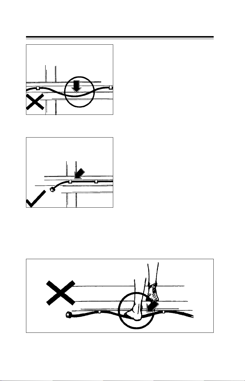
Take care that PA tubes do not touch hot objects such as exhaust pipe. This will
avoid burning or melting of PA tube.
Avoid PA tube to touch exhaust pipe Do not light fire near P A tube
Clamp PA tubes properly to avoid coming in contact with hot objects
Sharp objects
Take care that PA tubes do not come in contact with sharp objects. This will
avoid cutting of PA tubes.
P A tubes should not touch sharp objects Follow original routing of PA tubes
17
Page 22
1.5 Body building General
Loose fitments
Do not allow loose fitting of PA tube.
Avoid loose fitting of PA tube
Ensure proper clamping of PA tubes
Misuse
Do not step or hang on connected PA tube. Doing so, will lead to damage of
PA tube at the clamps or near end fitting, resulting in leakage.
Do not step on or hang on to PA tube
18
Page 23

1.5 Body building General
Tube Fitment
In case refitting of PA tube is required
z Follow original routing of PA
tube.
z Take care that PA tubes are not
forcibly bent or fitted.
Do not tighten nut without holding PA
tube
Hold PA tube before tightening nut
Twisted tube
z Use plastic coated clamps.
z Use both hands while fitting PA
tube. This will avoid twisting and
kinking of PA tube .
Kinked tube
19
Page 24

1.6 Additional fitments General
A) Rear under run protection device (RUPD)
This device is factory fitted on truck version.
Rear under run protection device fitted on vehicle (LPT)
B) Side under run protection device (SUPD)
LOAD BODY
D
B
OVER ALL LENGTH
AC
G
P2P1EJ
BOTTOM
OF FLOOR
H
Fitment of SUPD on LPT version
Note : While the SUPD is fitted as OE on vehicles with OE load body, customers
have to ensure fitment of SUPD when they do body building. Please refer
fitment details of SUPD.
20
Page 25

1.6 Additional fitments General
NOTE :
1. For all other technical
requirements of side
protection device ref.
IS:14682:1999.
2. Pitch ‘P1’, ‘P2’, ……..should
not be more than
1650 mm.
3. Dimn ‘H’ is as measured on
the load bodies
manufactured by other
than Tata Motors supplied
load body.
4. As per the regulations,
following Dimensions need
to be maintained within
the specified values.
4.1 Dimension ‘A’ should
be less than or equal to
300 mm measured
from front tyre rear
face (for LPT vehicles)
or less than or equal to
100 mm. measured
from rear wall of cab in
case of SFC vehicles.
4.2 Dimension ‘B’ should
be less than or equal to
550 mm measured
from ground.
4.3 Dimension ‘C’ should
be less than or equal to
300 mm measured
from front face of rear
tyre.
4.5 Dimension ‘D' should
be less than or equal to
350 mm measured
from lower most face
of floor structure.
4.6 Dimension ‘E’ and ‘J’
should be less than or
equal to 120 mm.
5. Painting or powder coating
to be done for rust
prevention.
6. All the members as shown
in drg. are with minimum
cross sections and thickness
required.
7. Item no. 8 to be added at
the both ends to cover
item no. 7, to be welded to
both side guard panels.
8. # This dimensions (460 mm
of item no. 1) to be
changed to meet
regulations given in sl. no.
4.2 (dimension `B') and 4.5
(dimension `D').
9. Long side guards can be
provided with two pieces
with overlapping and with
suitable backing plate or
longitudinal gap of
maximum 25 mm is
allowed.
4.4 Dimension ‘G’ should
be greater than or
equal to 100 mm.
21
Page 26

1.6 Additional fitments General
SUPD Proposal 1
STEEL CROSS RUNNER
2 WELD NUTS
B
B
ITEM NO. 4
HEX. FLANGED SCREW
M10x20-IS 17130-8.8
M10
ITEM NO. 2 & 3
ITEM NO. 5
ITEM NO. 1
C
20
20
LOAD BODY
MAX. WIDTH OF
10
20
C
D
THIS SURFACE SHOULD BE
INSIDE THE MAX. WIDTH OF
VEHICLE AND SHOULD NOT BE
MORE THAN 120 mm INSIDE.
E
HEX. FLANGED SCREW
M10x20-IS 17130-8.8
ITEM NO. 8
ITEM NO. 6
ASSY. SUPPORT SIDE GUARD
96
50
SECTION - BB
MATERIAL - SHT. 4 THK.
DD 1079 SS: 4013A
56
50
ALTERNATE FOR
SECTION - BB
MATERIAL - SHT. 2.5 THK.
DD 1079 SS: 4013A
202020
VIEW FROM - D
( ITEM NO. 2 AND 3 NOT SHOWN)
VIEW FROM - E
SECTION - CC
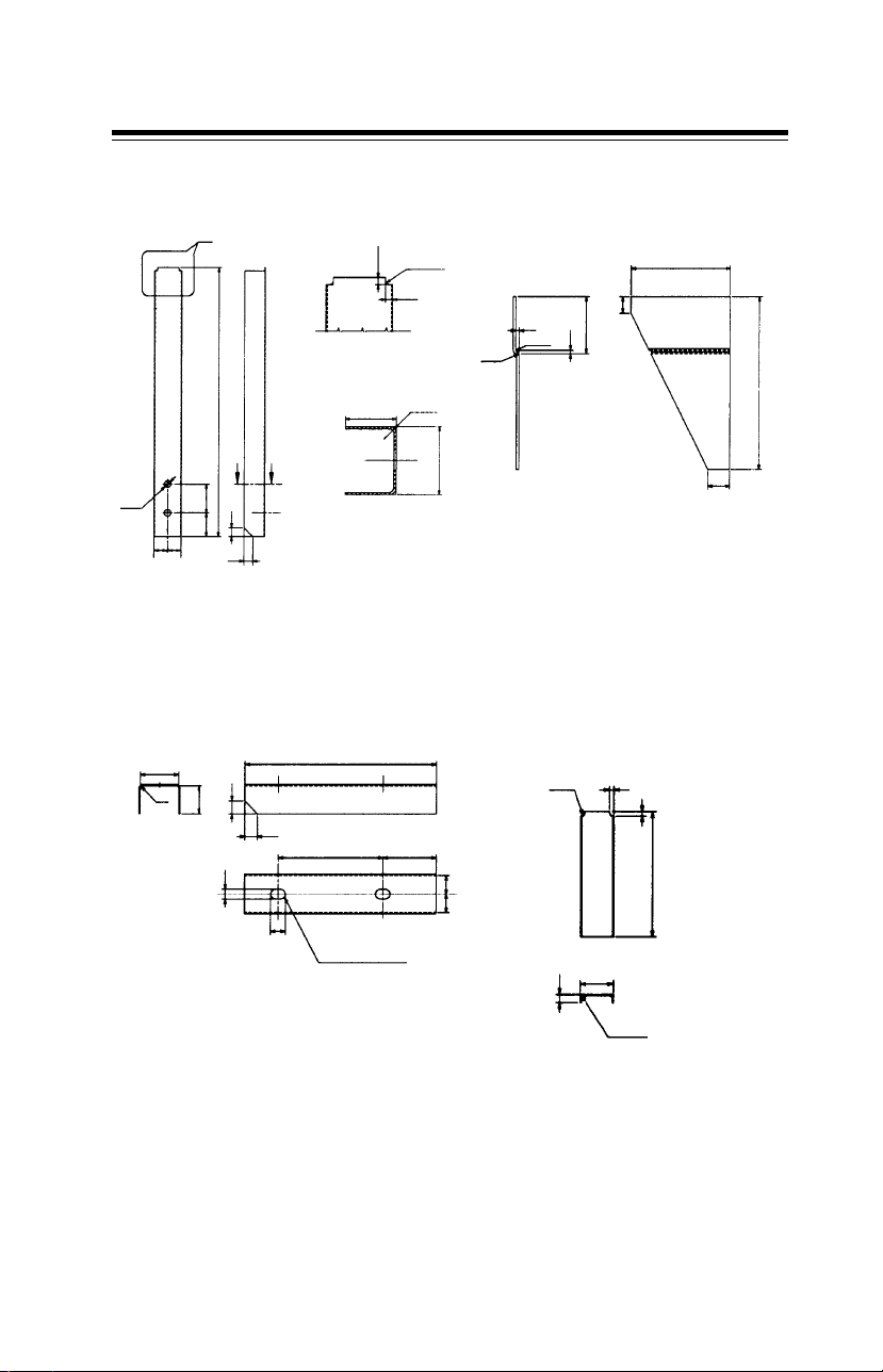
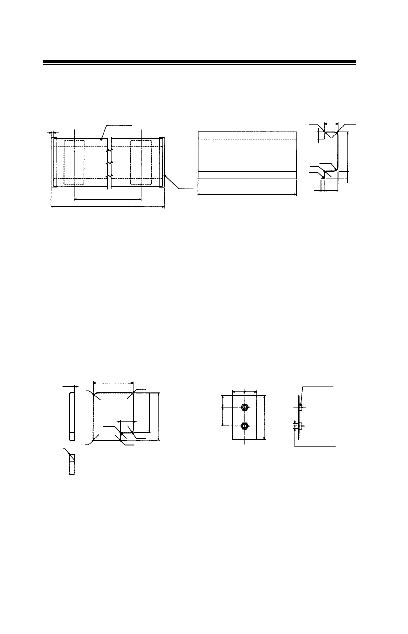
Note : Please refer page numbers 23 to 24 for details of item no. 1 to item
no. 9 & for alternate proposals.
22
Page 27
1.6 Additional fitments General
ITEM NO. 1 ITEM NO. 2 AND 3 (RH & LH)
`X'
50
10
105
15
460 #
A
A
11 DIA (TYP)
MATERIAL - SHT 1.6 THK. D513 SS: 4010
==
15
15
35
15
5 (TYP)
DETAILS -`X'
34.5
SECTION - AA
R3 (TYP)
5 (TYP)
R4.5
2
35
R1.5
R3
45
2
MATERIAL - SHT 1.6 THK. D513 SS: 4010
ITEM NO. 4
46
R3
33
15
15
13
18
MATERIAL - SHT 1.6 THK. D513 SS: 4010
230
125
2 SLOTS 13 x 18
ITEM NO. 5
5R3
5
65
150
==
41
10
R4.5
MATERIAL - SHT 1.6 THK. D513 SS: 4010
23
Page 28
1.6 Additional fitments General
ITEM NO. 6
6
CENTRE LINE
OF ITEM NO. 9
ITEM NO. 8
ITEM NO. 7
PITCH
OVERALL LENGTH
CENTRE LINE
OF ITEM NO. 9
ITEM
NO. 8
ITEM NO. 7
(OVERALL LENGTH -12)
MATERIAL - SHT. 1 THK. D513 SS:4010
ITEM NO. 9
35
R5 R10
20
R10
R5
R5
3410
10520
24
12
R15
R10
R6
R3
(TYP)
MATERIAL - SHT. 1 THK. D513 SS:4010
105
33.5
R6
105
126
R6
R4
65
30
50
MATERIAL - SHT. 2 THK. DD 1079 SS:4013A
115
WELD NUT M10
-IS: 8856
2 HOLES 12.5 DIA-H11
Page 29

1.6 Additional fitments General
SUPD ALTERNATE PROPOSAL - 2 :
a) with mounting to wooden runner
b) Two alternate sections for panel (item no. 3)
A
FRONT OF VEHICLE
WOODEN RUNNER
F
F
BODY
OF LOAD
MAX. WIDTH
10
ITEM NO .-3
VIEW FROM -A
B
B
WOODEN RUNNER
C
C
BOTTOM OF SIDE WALL OF LOAD BODY
ITEM
NO .-1
ITEM
NO .-3
340
AVERAGE HEIGHT
100
MEASURED ON
DIFFERENT LOAD
BODIES.
980
540
ITEM NO .-2
ITEM NO .-4
GROUND
SECTIONAL VIEW - BB
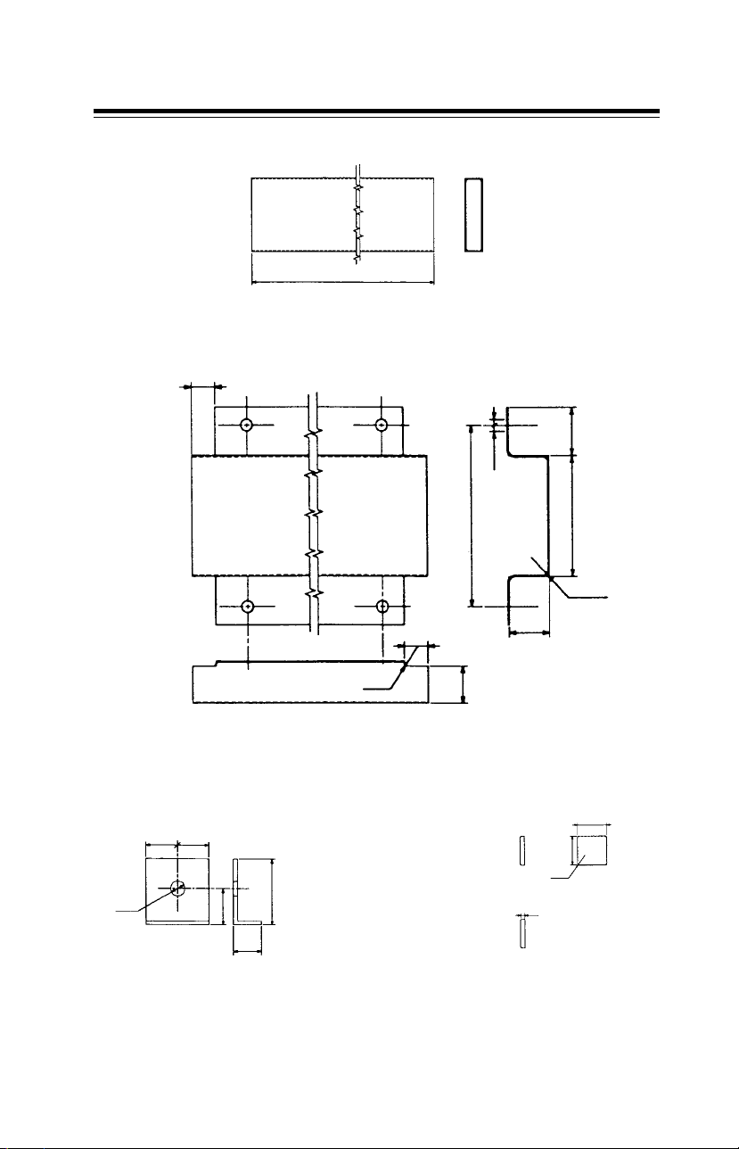
Note : Refer page number 26 for section CC and section FF. Details of item
no. 1 to item no. 4 are given on page number 26 and 27.
25
Page 30

1.6 Additional fitments General
HEX. BOLT M10x100
BRT. WASHER 10.5
SPRING WASHER B10
HEX. NUT M10
SECTION - FF
WOODEN CROSS
MEMBER
4x30x30
HEX. SCREW M8x20
BRT. WASHER 8.4
SPRING WASHER B8
HEX. NUT M8
SECTION - CC
PROPOSAL - A
Note - Refer item no. 3a, 3b, 4 and 5.
ITEM NO. 1
6 HOLES 11 DIA.
R5
#72
(TYP)
MATERIAL - SHEET 2 THK. DD 1079 SS:4013A
# DIMN. TO SUIT WOODEN CROSS MEMBER
( REF- CROSS SECTION -FF )
85
250
ITEM NO. 3a
85
ITEM NO. 3b
SECTION - CC
PROPOSAL - B
ITEM NO. 2
230
3x30x30
40
40
#240
4 HOLES 12 DIA
MATERIAL - ANGLES 45x45x3 THK. Fe 410W A IS : 2062
SECTION - DD
45
PLATE 3 THK.
150
20
D
D
EE
0
15x45
SECTION - EE
478
26
Page 31
1.6 Additional fitments General
ITEM NO. 3a - PROPOSAL - A
LENGTH OF SIDE PANEL
MATERIAL - RECTANGULAR TUBE 100x25x1.5 THK (MINIMUM) HF YST 210 IS : 4923
ITEM NO. 3b - PROPOSAL - B
20
20
R2
MATERIAL - SHEET 1 THK. D 513 SS : 4010
ITEM NO. - 4 ITEM NO. - 5
45
10 DIA
45
25
40100
10 DIA
150
R5
(TYP)
35
30
105
102
R5
(TYP)
15
20
MATERIAL - SHEET 3THK. Fe410 -1079 SS : 4013A
MATERIAL - SHEET 1 THK. D 513 SS : 4010
27
Page 32
1.6 Additional fitments General
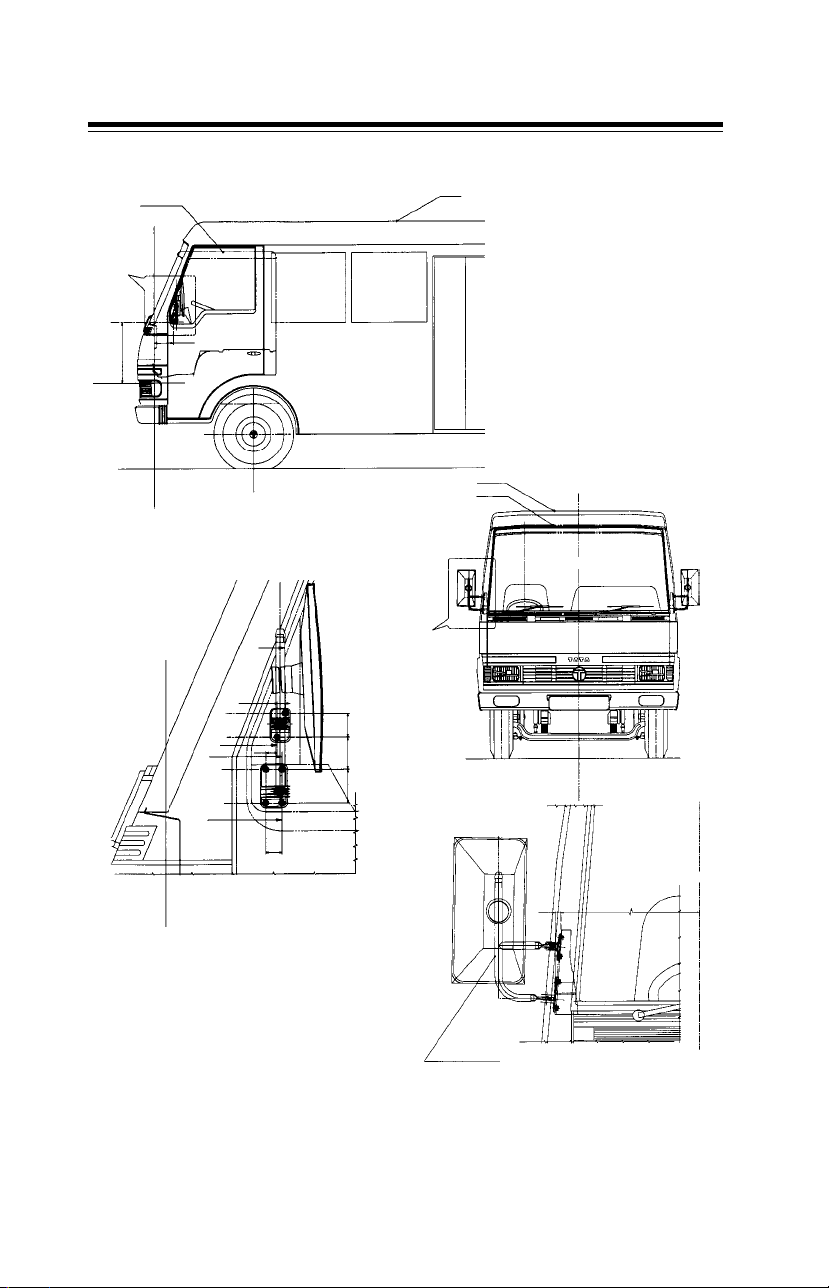
C) Rear view mirror - LP / LPT versions
BUS BODY
TRUCK BODY
BUS BODY
TRUCK CAB
`A'
210
640
(Z=20)
(X= - 1070)
(X= 0)
B
ASSY. REAR
VIEW MIRROR R.H.
100810
(Y= 0) (center line of vehicle)
DETAILS OF `B'
(X= - 1070)
16.5
D
C
C
DETAILS OF `A'
D
50
23
33
68
70
Note : Rear view mirror will be supplied as a kit with cowl and faceless chassis
and should be fitted during body building. Factory built cab and bus will be fitted
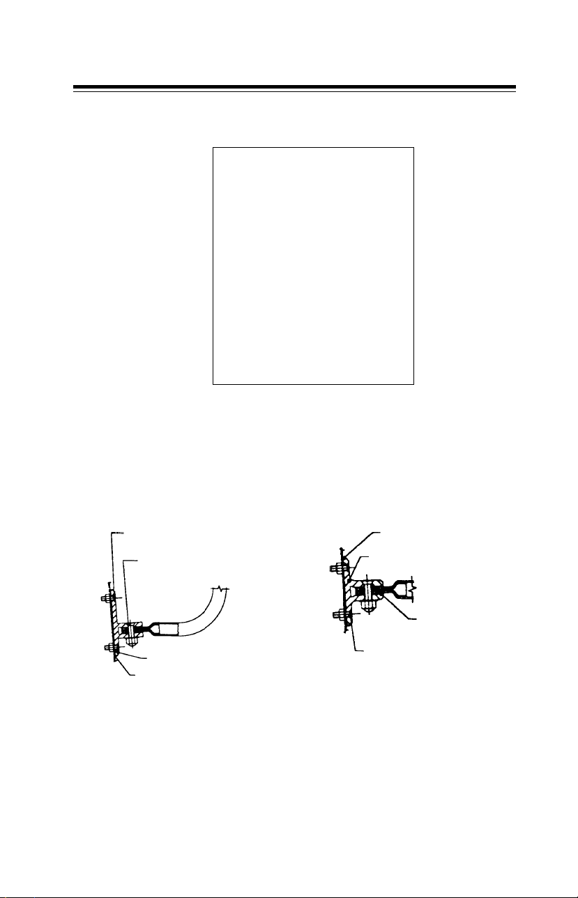
with rear view mirror. Please refer section -CC and section - DD on page 29.
28
Page 33
1.6 Additional fitments General
Rear view mirror - LP / LPT versions
Mirror for custom built cab
For LCVs there will be two plain mirrors one each at driver side and
co-driver side.
SL. CSK SCREW M6x20 - 4.8
WASHER C 6.4 SPR. st 130
SL. CSK SCREW M8x30 - 4.8
SPR. WASHER B8
DOME CAP NUT M8
BRACKET BOTTOM
RUBBER PAD BOTTOM
SECTION - CC
RUBBER PAD TOP
BRACKET TOP
SLEEVE FOR FRAME
SL. CSK SCREW M6x20 - 4.8
WASHER C 6.4 SPR. st 130
SECTION - DD
29
Page 34

1.7 Additional provisions (electrical) General
D) WIPING SYSTEM
GUIDELINES FOR FITMENT OF WIPER
SYSTEM BY BODY BUILDERS
1. Wiper system components
(wiper motor, wheel box,
wiper arm and blade, linkages)
are supplied along with the
drive away chassis and these
are recommended for use on
the built up vehicle. However,
the windscreen and the
mounting of the wheel boxes
should be appropriately
decided to match wiper
system regulation as stipulated
in AISO 11-2001 for A, B, C
wiping zone area
requirements.
2. Wiper motor to be mounted
preferably near the centre of
the panel below the wind
screen with suitable mounting
bracket.
rubber edge of blade against
the wind screen.
7. Wiper system should be
balanced and it is to be
ensured that there is no
possibility of entangling /
locking of linkages or fouling
of wiper blade with rubber
beading.
4. Wheel boxes to be fitted with
suitable mounting
arrangement on both sides, in
such a way that the wiping
pattern obtained meets the
regulatory requirements of
AISO11-2001.
5. The path of link rod
movement, during wiping
system operation, should be
free from any obstacles to
ensure free movement.
6. Wiper arm and blade
assembly should be properly
tightened on the wheel box
to ensure proper pressing of
30
Page 35

1.7 Additional provisions (electrical) General
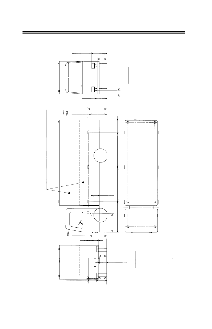
LIGHTING AND SIGNALLING
Guidelines for fitment of end
outline marker lamp, side marker
lamp, side retro-reflector, side
indicator, front fog lamps and
rear fog lamp, head lamps, tail
lamp assembly and side retroreflector during body building
(refer figure)
For factory built load body all the
above fitments come as OE, except
fog lamps.
Front and rear fog lamps are optional
and only provision is given.
1. End outline marker lamps: A, B,
C, D, E and F in the sketch are typical
six locations of End outline marker
lamps. Normally four lamps are fitted,
two for the front (white light) and
two for the rear ( red light ). The rear
lamps can be fitted at locations
suitably to be visible from the rear
of the vehicle. Visibility for both front
and rear lamps is defined as
horizontal spread about the lamp axis
of minimum +/- 80 deg and the
vertical spread of minimum 5 deg
above and minimum 21 deg below
the axis of the lamp. They are
normally mounted near the top of
the vehicle; the height should be
such that it is minimum 200 mm
above the parking lamp. From the
sides of the vehicle, the lamps
should be fitted at a distance less
than 400 mm. Refer figure. The
wattage of the lamps should be 5
watts.
2. Side ( turn ) indicator lamps : G
and H are the typical locations of
side indicator (turn indicator) lamps.
The height restrictions of the lamp
are given in the figure. The wattage
of the lamp should be normally 10
watts.
3. Side marker lamps & Side
retro-reflectors: I,J,K,L,M and N are
the typical locations of side marker
lamps and side retro reflectors. These
are to be fitted on all vehicles of
overall length more than 6 meters.
The distance restrictions are given in
the figure. The side marker lamp
and side retro reflector may be
separately fitted or can both be
included in a single package. The
wattage of side marker lamp should
be 5 watts. The distance restrictions
are given in the figure. Refer figure
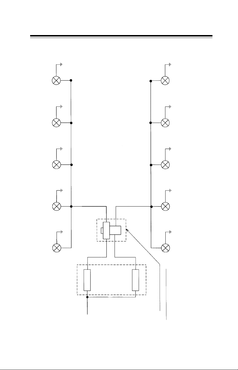
for circuit diagram.
4. Front fog lamps: P and Q are the
typical locations of the front fog
lamps. The distance restriction from
the sides of the vehicle and the
height are given in the figure for
Front and Rear fog lamps. The
wattage of the lamps should be 55
watts each. Refer figure for circuit
diagram.
5. Rear fog lamp: R is a typical
location of the rear fog lamp. The
distance restrictions from the
longitudinal centre line of the
vehicle and from the side of the
vehicle are given in the figure for
Front and Rear fog lamps. The rear
fog lamp is to be fitted on the
driver’s side of the vehicle typically
as shown in the figure. The wattage
of the lamp should be 21 watts. Refer
circuit schematic.
6. Head lamps: The head lamps are
supplied along with the vehicles
from the factory. The distance
restrictions for mounting of the
lamps during body building are given
in the figure .
7. Tail lamps: The tail lamp
assemblies are fitted as part of
factory supplies on our vehicles. The
assembly consists of rear position
lamp, stop lamp, rear retro-reflector,
reversing lamp and turn indicator.
The distance restrictions for
mounting the lamp assembly are
given in the figure .
31
Page 36
1.7 Additional provisions (electrical) General
UP TO 1200
D
T
250 (MIN)
A
X
C
TYPICAL LOAD BODY (OF DIFFERENT
HEIGHTS)
B
A
HEAD LAMPS & TAIL LAMP ASSEMBLIES ON MCVs/HCVs/LCVs
Y
PQ
S
MAX. UPTO HEAD LAMP TOP SURFACE
250 (MIN)
H
2300 (MAX)
1500 (MAX)
★
100 (MIN)
✤
U
500 (MIN)
UP TO
✤
LAMPS / SIDE RETRO REFLECTORS, SIDE INDICATOR LAMPS, FRONT & REAR FOG LAMPS,
GUIDE LINES TO BODY BUILDERS FOR FITMENT OF END OUTLINE MARKER LAMPS SIDE MARKER
400 (MAX)
2100 (MAX)
★
1500 (MAX)
✤
V
400
(MAX)
1000
(MAX)
4000 (MAX)
4000 (MAX)
3000 (MAX)
1800
UP TO
★
VIEW 'Y'
2000 (MAX)
1500 (MAX)
✤★
U
K
J
I
2500
1000 (MAX)
250 (MIN)
350 (MIN)
- Side retro reflector
A. B. C. D. E. - End out line marker lamp
G. H. - Side indicator lamp
I. J. K. L. M. N . - Side marker lamp /
P. O. - Front Fog lamp
R. - Rear Fog lamp
S. T. - Head lamp
U. V. - Tail lamp assembly
R
C
B
A
P
VIEW 'X'
V
F
N
M
E
L
H
D
O
not permit to maintain
dimension marked with `✤', it
Note : If vehicle structure dose
may be increased to respective
dimension marked with `H'.
are applicable for bus body applications also.
1) This is a typical truck with load body . The fitment requir ement for the various lamps
2) Refer attached notes.
32
Page 37
1.7 Additional provisions (electrical) General
0.5 Sq. mm BROWN
LAMP LH REAR
5W
LAMP RH REAR
END OUTLINE MARKER
5W
END OUTLINE MARKER
0.5 Sq. mm WHITE
0.5 Sq. mm BROWN
RH REAR
SIDE MARKER LAMP
SIDE MARKER LAMP
SIDE MARKER LAMP
* END OUT LINE
5W
0.5 Sq. mm BROWN
0.75 Sq. mm WHITE
RH MIDDLE
5W
0.75 Sq. mm WHITE
0.5 Sq. mm BROWN0.5 Sq. mm BROWN
RH FRONT
5W
0.75 Sq. mm WHITE
5W
MARKER LAMP RH FRONT
0.5 Sq. mm GREY
0.5 Sq. mm BROWN 0.5 Sq. mm BROWN
0.5 Sq. mm BROWN
0.75 Sq. mm GREY
0.75 Sq. mm GREY 0.75 Sq. mm GREY
0.5 Sq. mm BROWN 0.5 Sq. mm BROWN
5W
LH REAR
5W
SIDE MARKER LAMP
LH MIDDLE
5W
SIDE MARKER LAMP
LH FRONT
5W
SIDE MARKER LAMP
* END OUT LINE
MARKER LAMP RH FRONT
FUSE 10A
FUSE 10A
CONNECTIONS TO BE
TAKEN FROM THIS POINT
CONNECTION SCHEMATIC FOR SIDE MARKER LAMPS / END OUTLINE MARKER LAMPS - REAR
'PARKING LAMP ON'
O/P FRO COMBI SWITCH
during body building.
NOTES :
2) All earthing connections should be on frame or body at suitable locations.
1) This is a schematic and is to be used as guide line for connecting side marker lamps / end out line marker lamps-rear
33
Page 38

2. Know Y our Vehicle
2.1 Vehicle identification ...................................................37
2.2 Location of aggregate numbers ...............................41
2.3 Instrument panel ...........................................................43
2.4 Switches, gauges & indicators ...................................44
2.5 Driving controls ..............................................................55
2.6 Turbocharger ...................................................................57
2.7 Charge air cooler ...........................................................58
2.8 Clutch booster ................................................................59
2.9 Cab tilting .........................................................................60
2.10 Heating..............................................................................65
2.11 Driver seat & seat belt..................................................66
35
Page 39

2.1 Vehicle identification Know Your V ehicle
LPT 613 - Full forward control truck with tilt cab (RHS view)
LPT 613 - Full forward control truck with tilt cab (LHS view)
37
Page 40

2.1 Vehicle identification Know Your V ehicle
CHASSIS TYPE DESIGNATION
Description Wheel Chassis Sales
base type designation
LPT VERSIONS
FULL FORWARD CONTROL CHASSIS WITH 3800mm 381 325 LPT 613/38
CAB AND WITHOUT LOAD BODY, TRUCK
VERSION WITH 697TCIC BHARAT STAGE-II
ENGINE, WITH FULL AIR S’CAM BRAKE
WITH HEATING AND DEMISTING,
3800mm W.B.
FULL FORWARD CONTROL CHASSIS WITH 3800mm 381 327 LPT 613/38
CAB AND WITHOUT LOAD BODY, TRUCK
VERSION WITH 697TCIC EURO-II / BHARAT
STAGE-II ENGINE, WITH FULL AIR S’CAM
BRAKE, 3800mm W.B.
LP VERSIONS
FULL FORWARD CONTROL CHASSIS 3800mm 381 224 LP 613/38
WITHOUT FACE BUS VERSION WITH
697TCIC EURO-II / BHARAT STAGE-II
ENGINE WITH FULL AIR S’CAM
BRAKE 3800mm W.B.
FULL FORWARD CONTROL CHASSIS WITH 3800mm 381 225 LP 613/38
COWL BUS VERSION WITH 697TCIC
EURO-II / BHARAT STAGE-II ENGINE
WITH FULL AIR S’CAM BRAKE WITH
HEATING AND DEMISTING ,
3800mm W.B.
38
Page 41
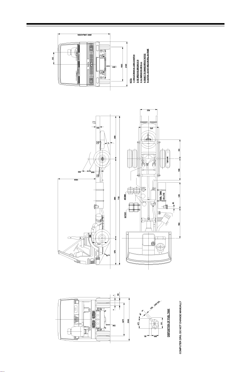
2.1 Vehicle identification Know Your V ehicle
LP 613 CHASSIS WITH COWL 38 WB EURO- II (LHD)
39
Page 42
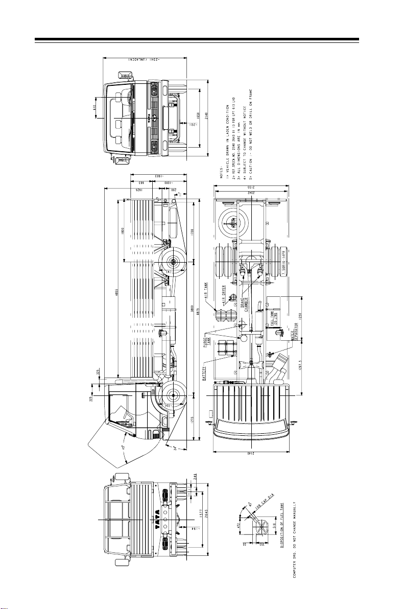
2.1 Vehicle identification Know Your V ehicle
40
LPT 613 CHASSIS WITH CAB AND LOAD BODY 38 WB EURO- II (LHD)
Page 43

2.2 Location of aggregate numbers Know Your Vehicle
1
2
1. Chassis number plate
2. Cab /Cowl number plate
Engine number plate
Cab / Cowl number plate
Engine number plate location
Chassis number - LHD
Chassis number plate
41
Page 44

2.2 Location of aggregate numbers Know Your Vehicle
Power steering gearbox number plate Front axle number plate
Gearbox number Rear axle number plate
42
Page 45
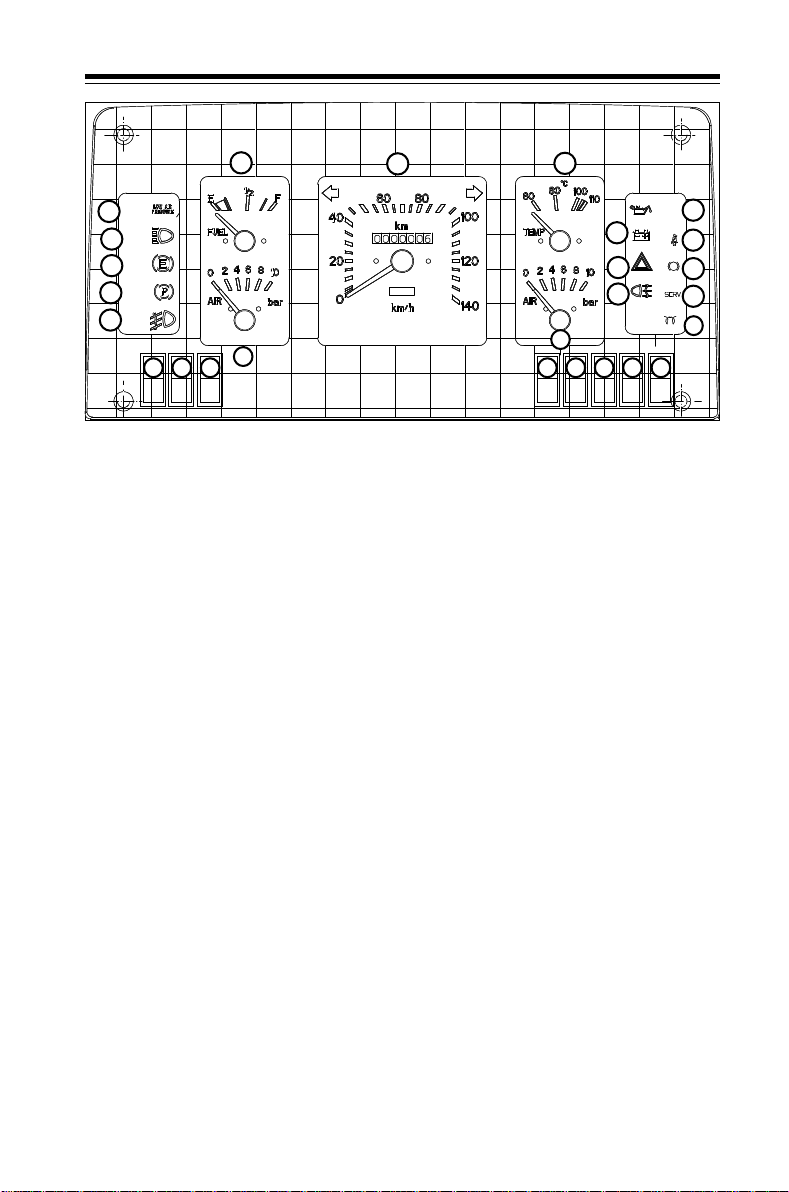
2.3 Instrument panel Know Your V ehicle
6 7 8
1
2
3
4
5
19 20 21 22 23 24 25 26
18
Instrument panel
1. Low air pressure indicator
2. High beam indicator
3. Exhaust brake indicator
4. Parking brake indicator
5. Front fog lamp indicator
6. Fuel gauge
7. Speedometer with odometer
8. Coolant temperature gauge
9. Low oil pressure indicator
10. Battery charging indicator
11. Seat belt indicator
12. Hazard warning indicator
13. ABS indicator (If fitted)
9
10
12
14
17
11
13
15
16
14. Rear fog lamp indicator
15. Air filter service indicator
16. Glow plug indicator
17. Air pressure gauge (II)
18. Air pressure gauge (I)
19. Exhaust brake isolator switch
20. Front fog lamp switch
21. Blank
22. ABS switch (If fitted)
23. Head lamp leveling knob
24 . Blank
25. Rear fog lamp switch
26. Engine compartment lamp
switch
43
Page 46

2.4 Switches, gauges & indicators Know Your V ehicle
Fuel gauge
Fuel gauge indicates the level of
fuel in tank. It is electrically operated.
Fuel level is indicated on gauge
through a sensing unit mounted on
fuel tank.
Coolant temperature gauge
Tempera ture gauge indic ates coolant
Fuel gauge
Coolant temperature gauge
temperature. It senses coolant
temperature through a transducer
mounted on upper cooling line.
When gauge needle touches red
band on dial it indicates engine over
heating.
If overheating is observed & coolant
level in auxiliary tank found to be
low, stop engine and allow it to cool
down. T op up c oolant water mixture
in 1:1 ratio through auxiliary tank
filler neck.
Cylinder head may crack, if coolant
mixture is topped up when engine
is hot.
Speedometer
Air pressure gauge
44
Speedometer
It indicates vehicle speed in kmph
and also the distance covered by
vehicle in km. This is driven by a
flexible shaft connected to the
output shaft of gear box. High beam
indicator is also provided on
speedometer dial.
Air pressure gauges
Two air pressure gauges have been
provided, one each for front and rear
brake circuits. Vehicle should not be
driven till a minimum air pressure of
5.6 bar is reached in both air tanks.
Regulated cut out air pressure is
7.4 ± 0.2 bar and cut in pressure is
6.2 bar min.
Page 47

2.4 Switches, gauges & indicators Know Your Vehicle
SERV indicator
When it glows, it indicates that the
Air cleaner filter is choked. Filter
needs to be cleaned/ replaced.
When the ignition key is in ON
position, before starting the engine
this indicator should glow
SERV indicator
GLOW indicator
This indicator is used to indicate the
functioning of Flame start system.
When the ignition key is in ON
position, before starting the engine,
if the engine coolant temperature is
GLOW indicator
less than 20OC, wait to crank till the
indicator glow continuously and
proceed to crank the engine once
the indicator start blinking. If the
engine coolant temperature is more
than 20OC, the indicator blinks
continuously i.e. ready to start.
Front fog lamp indicator
Low air pressure indicator
Rear fog lamp indicator
Front fog lamp indicator
This indicator will glow only when
Front fog lamp is switched on.
Low air pressure indicator (Red)
Two low pressure (LP) switches one
each for front & rear brake circuits are
connected at dual brake valve. When
pressure in any one or both the
circuits is less than specified value,
these switches activate low air
pressure indicator.
Rear fog lamp indicator
This indicator will glow when rear fog
lamp is switched ON.
45
Page 48
2.4 Switches, gauges & indicators Know Your V ehicle
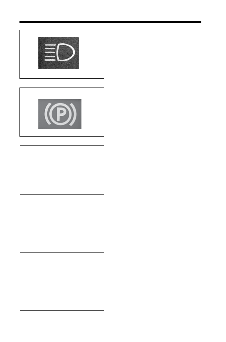
High beam indicator
When it glows, it indicates that the
head lights high beams are on. It is
provided in speedometer dial.
High beam indicator
Parking brake indicator
This indicator comes ON when
parking brake is applied and goes
OFF when it is released. It will also
glow when air pressure in parking
brake circuit is less than 4.6 bar.
Parking brake indicator
Battery charging indicator
When it glows, it indicates that
battery is not getting charged, i.e.
during idling or when alternator is
defective with normal engine
running. When ignition key is in ON
position, before starting the engine
Battery charging indicator
Low oil pressure indicator
Side indicators
this indicator should glow.
Low oil pressure indicator
This indicator glows when ignition
key is in ON position before starting
engine. It should go off after starting
the engine, when oil pressure builds up.
If indicator continues to glow even
after the engine has started, stop
the engine, trace out the fault in
lubrication system / electrical
connections and rectify.
Side indicators
Side indicator with arrow pointing
towards left will glow, when combi
lever is moved for LH indication.
Similarly side indicator with arrow
pointing towards right will glow, when
combi lever is moved for RH indication.
46
Page 49
2.4 Switches, gauges & indicators Know Your Vehicle
Exhaust brake indicator
This indicator comes ON when
exhaust brake is in operation
Exhaust brake indicator
Hazard warning indicator
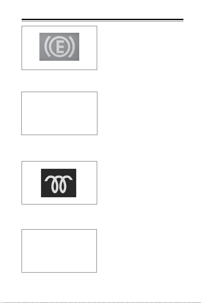
Glow plug indicator
ABS indicator
Hazard warning indicator
It comes 'ON' when hazard warning
lights are switched 'ON' to warn the
other road users about the
hazardous condition of vehicle.
Glow plug indicator (Amber)
It glows when the ignition key is
turned to position ‘ON’ and after a few
seconds it goes ‘OFF’ indicating that
engine can be started.
If glow plug indicator light does not
go off automatically, get it checked.
ABS Indicators (if fitted)
ABS indicator light on instrument
cluster illuminates approx. for 5 sec.
when the ignition key is turned to
‘ON’ position. This is normal and
indicates the system is performing a
self check. If the light does not
illuminate when ignition is ‘ON’ or
remains illuminated after initial self
check and while driving or flashes,
fault may exist in the ABS system.
In this case also the normal braking
system is still effective and can able
to provide normal stopping ability.
In this condition it is recommended
to taking your vehicle to the nearest
Dealer / service outlet and get your
vehicle attended as soon as possible
if the warning light stays on.
47
Page 50

2.4 Switches, gauges & indicators Know Your V ehicle
Seat belt indicator
It comes ‘ON’ when seat belt is not
fasten or belt tongue is not locked in
to buckle.
Seat belt indicator
Exhaust brake isolator switch
Exhaust brake can be made
inoperative, by exhaust brake
isolator switch, whenever required.
Exhaust brake isolator switch
Engine compartment switch
Provided to switch ON the bulb
located in engine compartment for
inspection purpose.
Engine compartment switch
Front fog lamp switch
Head lamp leveling knob
48
Front fog lamp switch:
This switch is provided to switch on
Front fog lamps. Front fog lamps are
operative only when the park lamps
are switched ON.
Head lamp levelling switch
A motorized head lamp levelling
arrangement with the setting knob is
provided near the instrument panel.
This switch has 4 positions viz. 0, 1, 2
and 3. Appropriate levelling position
can be set depending on the load.
Page 51
2.4 Switches, gauges & indicators Know Your Vehicle
Rear fog lamp switch:
This switch is provided to switch on
Rear fog lamps. Rear fog lamps are
operative only when the park lamps
along with Head lamps (Hi beam/
Low beam) or Front fog lamps are
switched ON.
Rear fog lamp switch
Mechanical stop light switch
A mechanical stop light switch is
mounted above brake control lever.
Whenever brake pedal is depressed
for applying brakes, stop light switch
comes into operation and lights at
rear tail lamp glow. This also activates
Mechanical stop light switch
engine exhaust brake solenoid valve
for exhaust brake application.
Electric service indicator switch
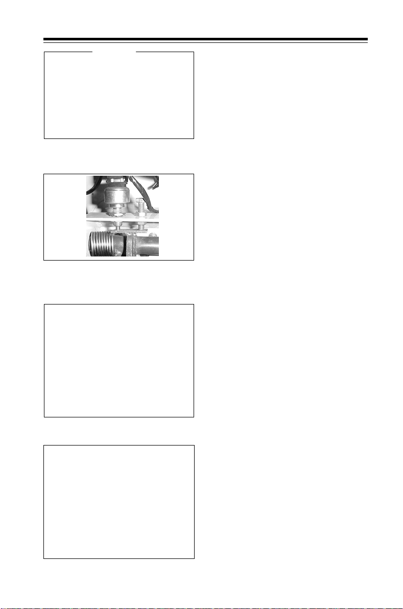
This switch is provided on air cleaner.
Switch contact takes place only
when the filter get chocked.
Electric service indicator switch
Air dryer heater
Air dryer heater
This heater is a part of air dryer assy.
This heater is provided to heat the
moisture if any in the air brake lines.
This heater gets switched ON at 70 C
of air temperature and OFF at 290 C
automatically.
49
Page 52

2.4 Switches, gauges & indicators Know Your V ehicle
Battery cut off switch
Bus chassis is provided with battery
cut off switch to isolate battery from
electrical system when required.
Battery is connected to starter motor
and other circuits through isolator
switch. This is to be switched off
Battery isolator switch
Steering lock cum ignition switch-key positions
while carrying out any electrical work
on the vehicle and also when vehicle
is parked for long duration.
STEERING LOCK CUM IGNITION SWITCH
Position of key Steering Electricals
Clockwise direction
‘LO CK’ without key Locked All OFF
‘L OCK’ with key Locked All OFF
‘ACC’ with key Unlocked ACC ON
‘ON’ with key Unlocked ACC + IG ON
‘START’ with key Unlocked IG + ST ON
Anti-clockwise direction
’ON’ with key Unlocked ACC + IG ON
‘ACC’ with key Unlocked ACC ON
‘L OCK’ with key Unlocked All off
‘LO CK’ without key Locked All off
(ACC = Accessories)
(IG = Ignition)
(ST = Start)
50
Page 53

2.4 Switches, gauges & indicators Know Your V ehicle
Steering lock cum ignition switch
It is located on right hand side of
steering column. It has following
positions.
‘LOCK’ Position
Key can be inserted or removed in
this position only. Steering wheel gets
locked, only when key is removed.
‘ACC’ Position
Steering lock cum ignition switch with
key (LHD)
Steering gets unlocked in this
position. Only accessories are ON.
‘ON’ Position
By turning the key to position ON, low
oil pressure lamp, battery charging
indicator lamp, parking brake
indicator lamp (if applied), fuel gauge
and temperature gauge are switched
on. Other electrical systems are
ready for operation. If none of the
above warning indicators /gauges are
working the chances are that the
fuse for engine and gauges is blown
off in which case engine will not
start.
‘START’ Position
Turn the key further clockwise to start
position to operate starter motor. This
is a spring return position.
As soon as the engine starts, release
ignition key so that the key can come
back to ON position and starter motor
disengages.
51
Page 54
2.4 Switches, gauges & indicators Know Your Vehicle
POSITION FOR FLASH
(HIGH BEAM)
POSITION FOR LOW
BEAM
POSITION FOR
HIGH BEAM
POSITION FOR WASH-ON
POSITION FOR LEFT
N
POSITION FOR RIGHT
Combination switch
4
2
3
1
5
Combination switch (LHD)
HAZARD WARNING SWITCH
Combination switch
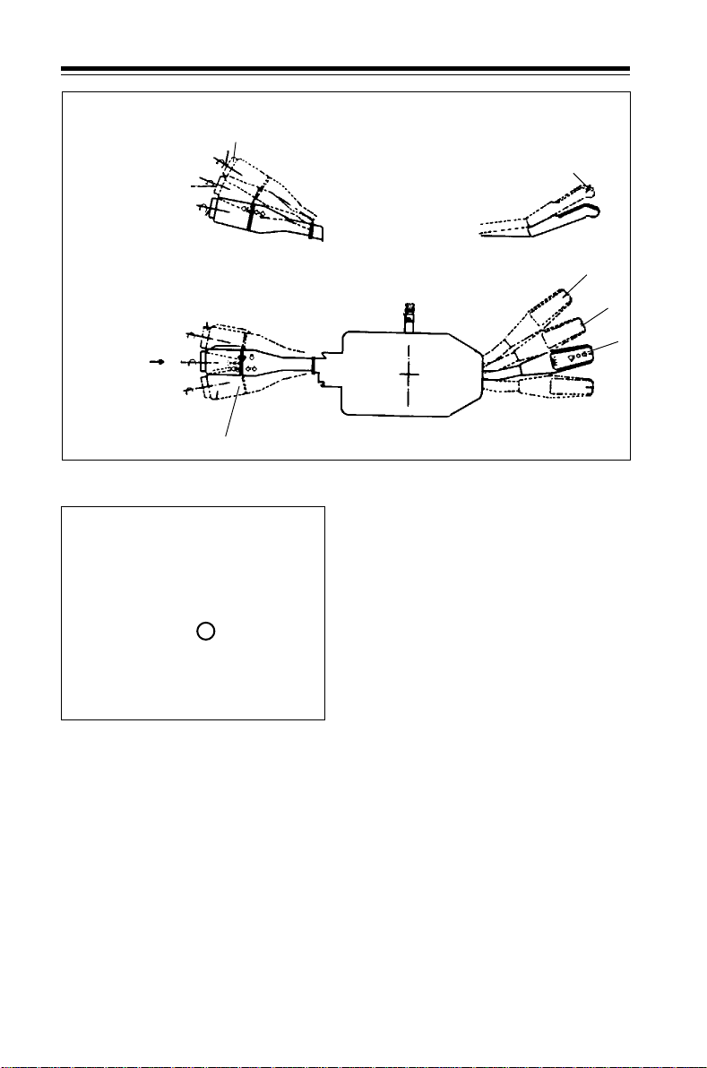
Combi switch is mounted on
steering column. It has 2 levers.
One lever is for operating turn
signals, head lamps, parking lamps
and number plate lamps. This lever is
mounted on RH side on RHD vehicles
and LH side on LHD vehicles.
Head lights
Position 1 - Low beam
Position 2 - High beam
Position 3 - High beam (flash)
Turn signals
Position 4 - Turn signal right
Position 5 - Turn signal left
Self cancellation turn signal
arrangement is provided. When turn
signal option is used, this lever will
return to neutral position on its own
when steering wheel is brought back
to straight ahead position.
HI
LO
INT
OFF
52
Page 55
2.4 Switches, gauges & indicators Know Your Vehicle
Lights
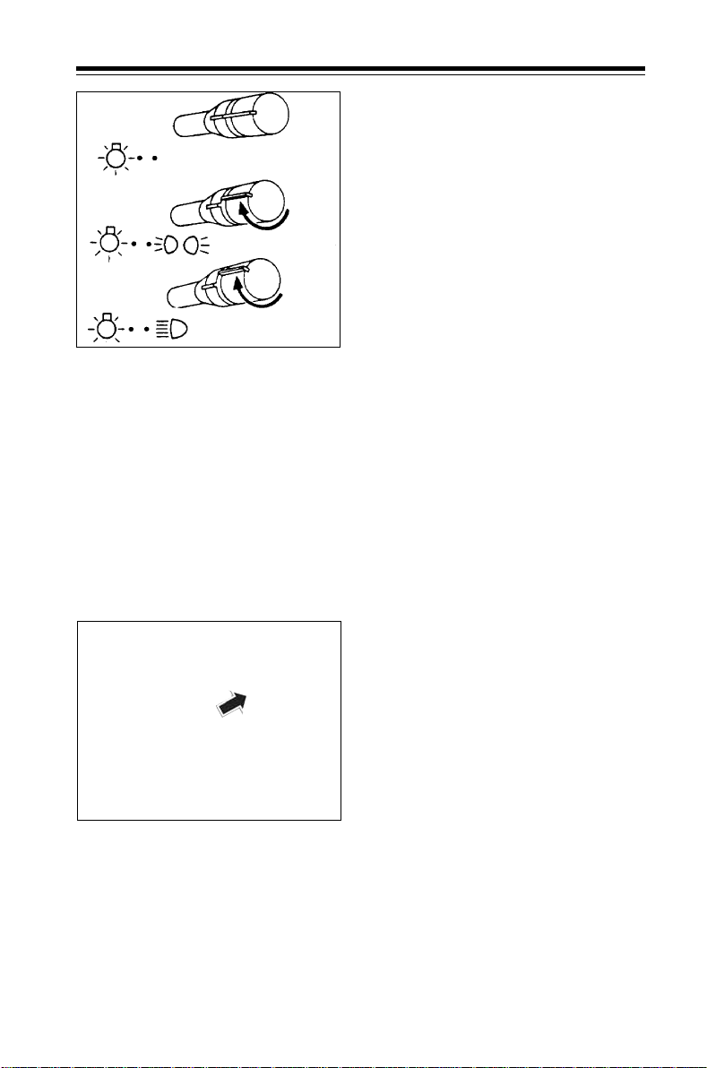
Lights are operated by turning the
OFF
OFF POSITION
'PL' POSITION
knob of this lever as indicated below
First notch (PL position)
Parking lights, instrument panel
lights, number plate lights, control
backlights and top marker lights are
switched ‘ON’.
'HL' POSITION
Light switch
Note :
High beam flash (No. 3 position)
High beam will be ‘ON’ as long as
lever is held in position '3'
irrespective of the knob position. T his
is spring loaded position and can be
used in day time for giving signal to
on coming traffic.
ON
OFF
Hazard warning switch
Second notch (HL position)
In addition to parking, instrument
panel, control backlights, number
plate lights and top marker lights,
headlights are also switched ON.
OFF-position
All lights are switched off in this
position.
Hazard warning switch
Combi switch assembly also has a
switch for operating hazard warning
device.
To switch ON hazard warning, pull
the knob located behind steering
wheel. All turn signals lights will flash
simultaneously to warn other road
users about the hazardous condition
of vehicle.
Push back this knob to original
position when hazard warning
requirement is over.
53
Page 56
2.4 Switches, gauges & indicators Know Your V ehicle
POSITION FOR WASH-ON
HI
LO
INT
OFF
Wiper motor operating lever (LHD)
Windshield washer water reservoir
Windshield wiper and washer
The lever on other side is for
operating windshield wiper and
washer. This lever is located on LH
side on RHD vehicle and RH side in
LHD vehicle.
Position
‘OFF’ - Wiper motor
switched ‘OFF’
‘INT’ - Wiper sweeps
intermittently
‘LO’ - Low speed of
wiper motor
‘HI’ - High speed of
wiper motor
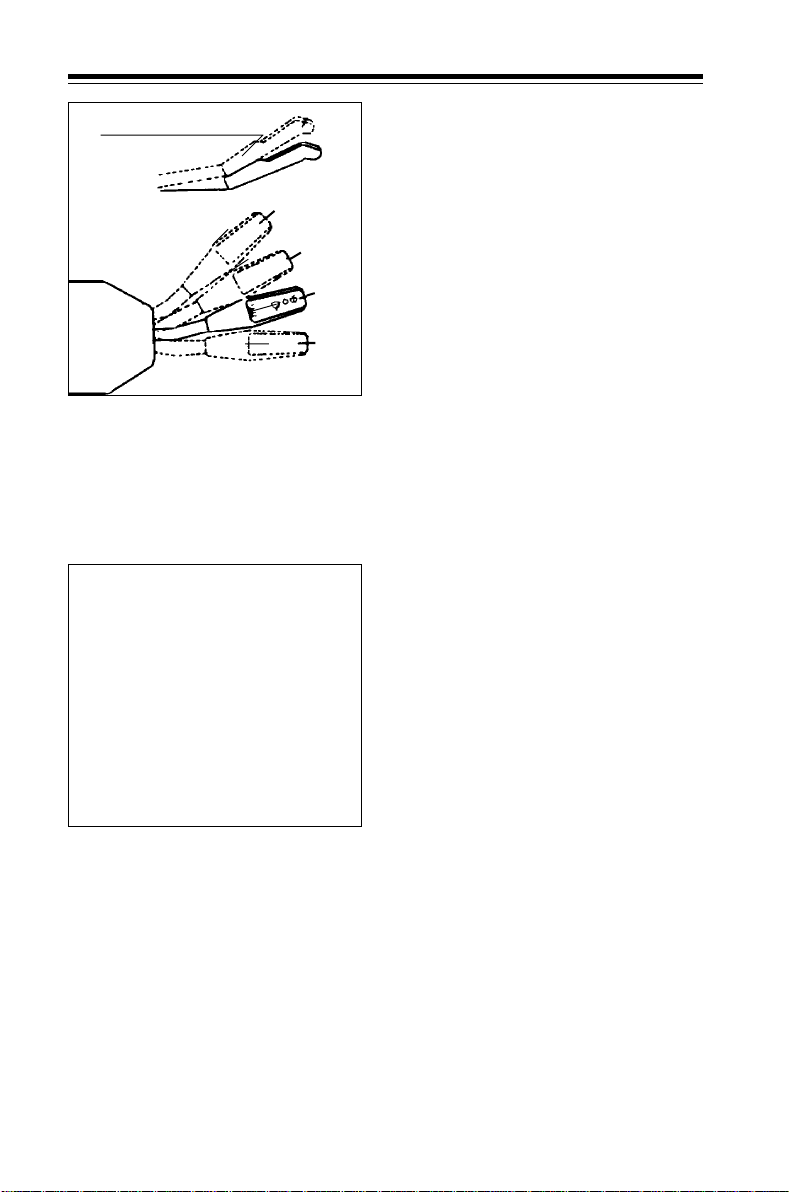
T o operat e windshield washer, lift the
lever. Windshield washer will remain
in operation as long as the lever is
held in this position.
When wind shield washer is
actuated, wipers are also switched
on. Wind shield washer water
reservoir is accessible after opening
centre flap. Top up reservoir with
clean water regularly. Do not use
soap solution. In cold climates, Use
methanol and water in the ratio
50:50 to avoid water freezing. Please
refer chapter no. 6.3 for details of
recommended antifrost and ratio for
varying ambient temperatures.
54
Do not operate windshield washer
more than ten seconds at a time.
Use methanol and water in the ratio
50:50 to avoid water freezing.
Page 57
2.5 Driving controls Know Your Vehicle
7
8
1
2
Driving controls LHD
6
5
10
9
3
4
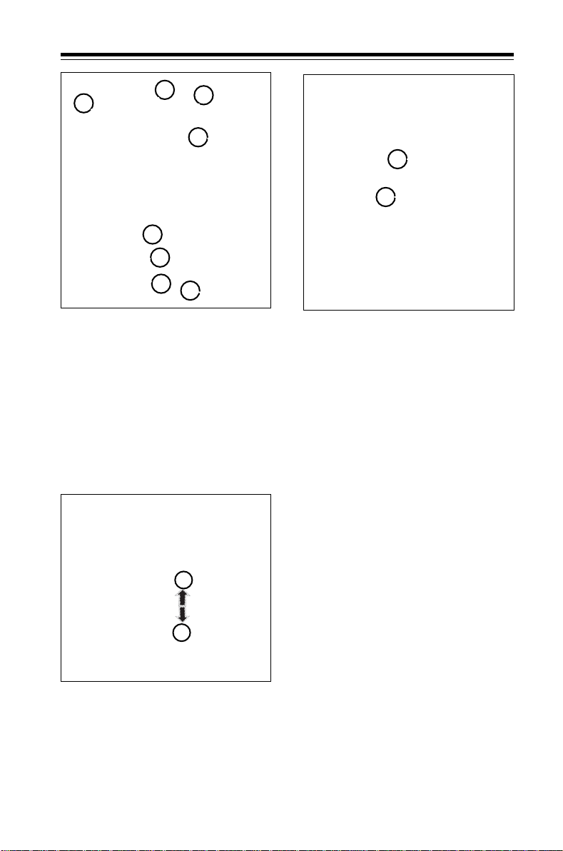
1. Accelerator pedal
2. Brake pedal
3. Clutch pedal
4. Parking brake
5. Gear shift lever
A
Hand brake valve
6. Steering wheel
7. Combiswitch lever (Lights)
8. Instrument panel
9. Steering lock cum ignition switch
10. Combiswitch lever (Wiper/
washer)
Hand brake (parking brake)
Hand brake is integral with spring
brake actuator on rear axle. Spring
brake chamber piston ram acts
B
directly on push rod assembly of
brake chamber.
A. Brake applied
B. Brake released
A to B Gradual application.
55
Page 58
2.5 Driving controls Know Your Vehicle
KSB unit (for Euro II vehicles)
KSB unit is a cold start throttle
advance mechanism. It is an integral
part of fuel injection pump.
KSB unit
- Provides necessary advance in
lower throttle operation during
cold condition.
KSB unit
- Allows a normal dynamic timing
during regular operation.
- Reduces white smoke, misfiring
in cold start and part throttle
operation.
During normal running of engine,
24 V supply continues to KSB unit
through thermo switch.
Opening/closing of front centre
flap
Pull to open the bonnet - LHD
56
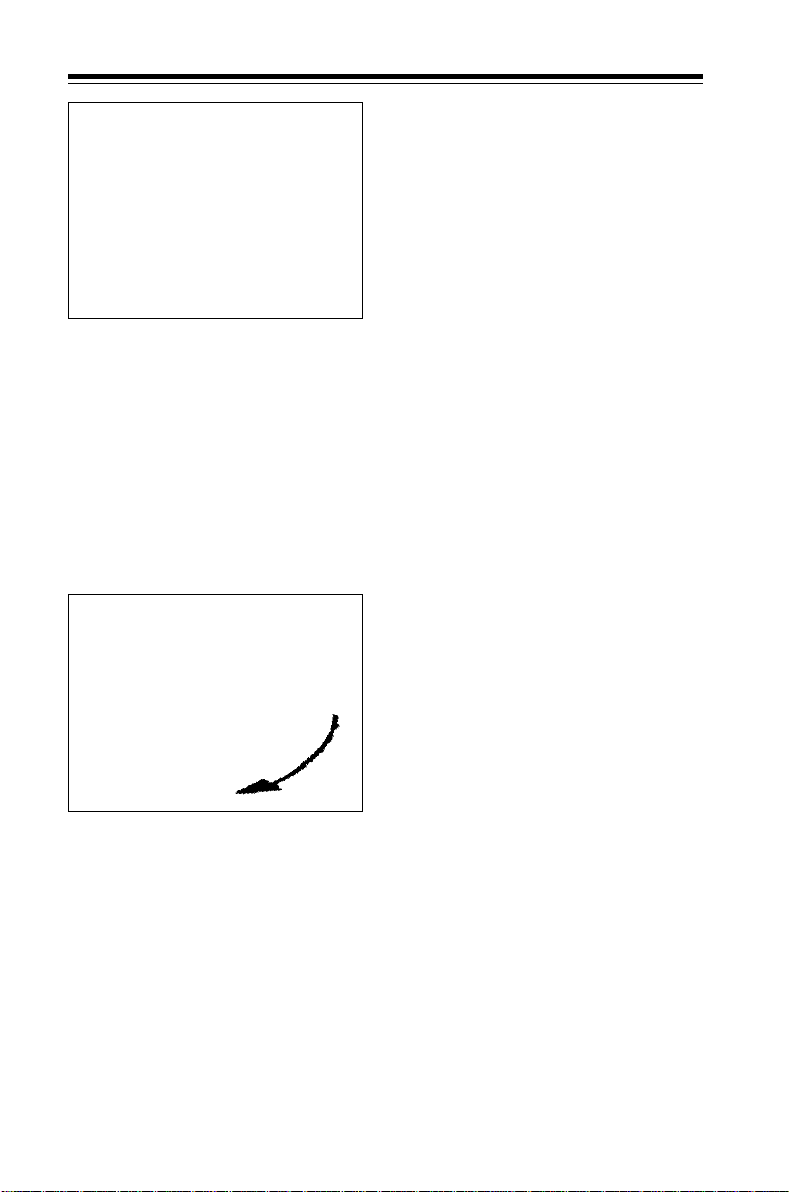
For opening centre flap, a lever as
shown has been provided. For LHD
vehicles it is located on LH side
above clutch pedal. To open centre
flap, pull this lever and lift centre flap.
A stay rod has been provided to keep
centre flap open position. To close
centre flap, remove stay rod. Slowly
drop centre flap and press it down to
make sure that it is locked.
Page 59

2.6 Turbocharger Know Your Vehicle
Turbocharger (Euro II)
Lubrication of the turbocharger
Rotor assembly of turbocharger is
supported by two floating lead
bronze sleeve bearings in the
bearing housing. These bearings are
lubricated with finest filtered and
cooled oil from lubrication system.
There is a heat shield arrangement
provided between turbine housing
and bearing housing to avoid heating
of the bearings.
Advantages of turbocharger
Turbocharged engine has following
advantages over naturally aspirated
engine of same size and weight.
1. Increased power is obtained with
the same engine dimensions
thereby increasing the power to
weight ratio. Thus, the engine is
lighter and payload value of the
vehicle is improved.
2. A turbocharged engine has a
lower specific fuel consumption,
so the vehicle consumes less fuel.
3. Turbocharger reduces black
smoke in the exhaust.
4. Loss of engine power at higher
altitudes is much less making it
ideal under all operating
conditions. Especially in hilly
areas, payload capacity is further
improved by this aspect.
5. Turbocharger acts as an additional
silencer on exhaust side, thus
reducing engine noise.
Maintenance of turbocharger
No adjustments or repairs are to be
carried out on the turbocharger. In
case of doubtful performance from
the engine because of
malfunctioning of turbocharger, take
your vehicle to T ata authorised workshop .
Following precautionary measures
should be taken to obtain trouble
free performance.
1. During regular engine inspection,
look carefully for any oil leakage
at the oil inlet banjo connection
on bearing housing. Do not run
engine unless leakage at this
point is rectified.
2. Do not stop the engine suddenly
as it may damage rotor bearings.
Allow engine to idle for atleast
3 minutes before switching it off.
Similarly, do not increase engine
speed suddenly.
Run the engine at low idle speed
for atleast 3 minutes after starting
to build up oil pressure before
increasing engine speed.
3. Since the speed of rotor assembly
is tremendously high, (nearly
1,00,000 rpm) it requires finest
filtered oil. Therefore, ensure
cleanliness of engine oil by
adhering to regular schedules of
engine oil and oil filter cartridge
change intervals.
4. As the unfiltered dust particles
entering compressor housing
may prove dangerous, make sure
that there is no leakage in air
intake system and that air filter
elements are in good condition
and sealings are perfect.
5. Insist on use of only
recommended grade of engine
oil, genuine engine oil filter and
air filter cartridges.
57
Page 60
2.7 Charge air cooler Know Your Vehicle
Charge air cooler (Euro II)
TURBOCHARGER
EXHAUST INLET
-
Charge air cooler
Advantages of charge air cooler
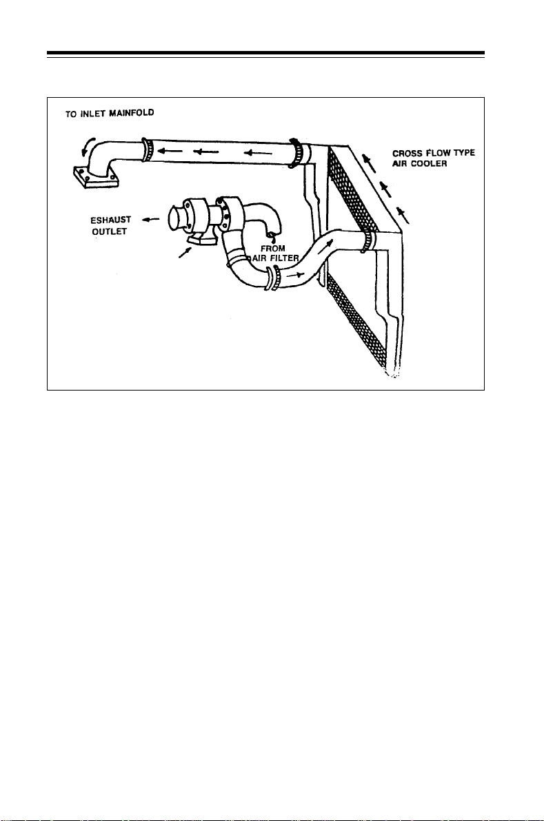
Hot air coming out of turbo charger
flows through charge air cooler and
gets cooled before entering intake
manifold, thus increasing density of
intake air for better combustion.
Charge air cooler is mounted in front
of radiator .
58
Page 61
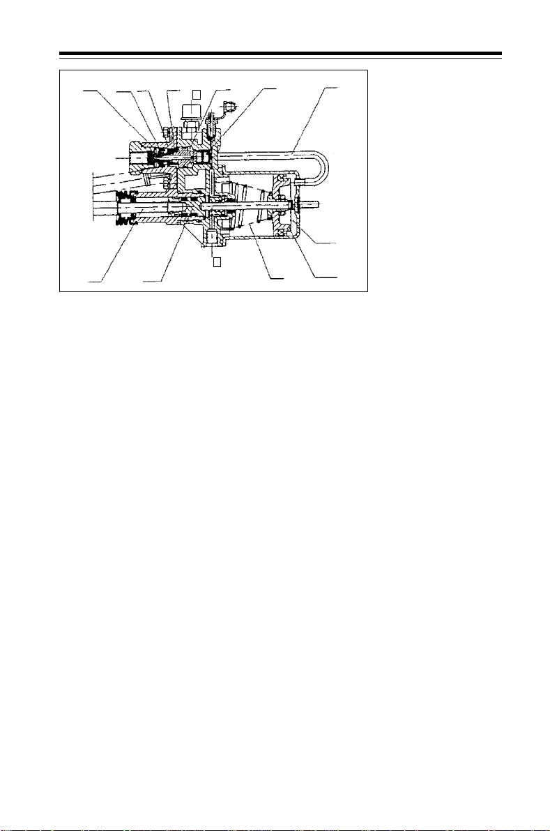
2.8 Clutch booster Know Y our V ehicle
8
A
1
10
5
B
3
C
3
4
Clutch Booster
Hydraulic clutch actuation system
with pneumatically operated clutch
booster has been provided to
reduce clutch pedal effort.In this
system, clutch booster replaces the
function of clutch slave cylinder.
Compressed air connection to
operate clutch booster has been
tapped from port No. 24 of system
protection valve.
Output rod of clutch booster is
connected to clutch release fork.
When there is no force on clutch
pedal, push rod (5), pistons (3 & 4)
are in stand still position due to the
force exerted by return springs (6 &
8).
When pedal is pressed to disengage
clutch, clutch fluid under pressure
enters throught port no. 4 and acts
on piston (3). due to this piston (3)
moves leftwards.
At the same time fluid under
pressure acts on controlling piston
(2) due to which piston (2) moves
leftwards to close air outlet and to
open air inlet (1) compressed air
2
6
7
D
4
Port 1. Inlet port (for
compressed air)
Port 3. Vent (for
compressed air) Port 4.
Control port (for clutch
fluid)
2. Piston
3. Piston
4. Piston
5. Push rod
6. Return spring
7. Wind pipe
8. Return spring
A.
B. Cavity
C.
D. Cavity
flows into air cylinder via wind pipe
(7).
Piston (4) moves leftwards and
exert force on piston (3) which in
turn pushes output rod to actuate
push rod (5). The force on piston (4
& 3) is proportional to the pressure
exerted by clutch fluid on piston (2).
When pedal is released to engage
clutch, clutch fluid pressure drops
to zero. By the action of return
spring (8) and air pressure at cavity
B, piston (2) moves rightwards to
close air inlet and to open air
outlet. Compressed air in cavity D
is exhausted to atmosphere. Return
springs (6 & 8) bring back pistons
(2 & 4) to stand still position and
hence push rod (5) retracts to its
original position.
Technical Data
Operating pressure : Clutch fluid 4
Mpa, compressed air 0.8 Mpa
Max. pressure : Clutch fluid 12 Mpa,
compressed air 1 Mpa
Operating Temp. range -40OC to
+80OC.
59
Page 62
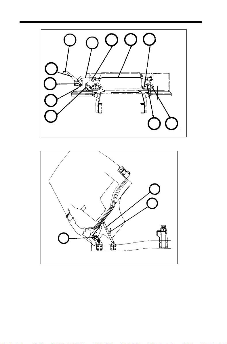
2.9 Cab tilting Know Your V ehicle
3
4
2
1
5
RELEASED POSITION BEFORE TILTING
6
8
7
Cab tilting and locking lever arrangement
9
14
10
13
11
12
RELEASED AND TILTED POSITION
1. Cam lever handle
2. Cam lever
3. Primary locking lever handle
4. Primary locking lever
5. Secondary locking lever
6. Connecting link - LH
7. Connecting link - RH
60
8. Cab mounting mechanism
9. Mounting pin
10. Mounting hook
11. Rubber pad
12. Torsion bar
13. Cab stay
14. Releasing lever
Page 63
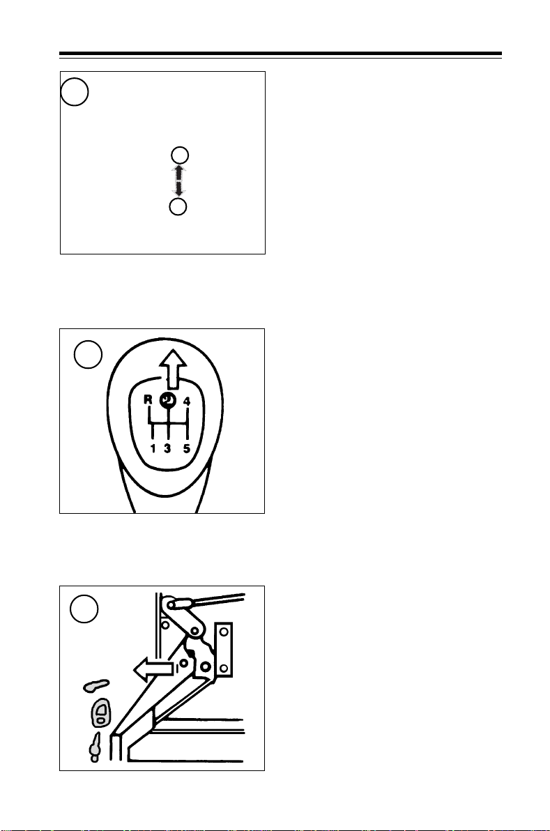
2.9 Cab tilting Know Your V ehicle
Cab Tilting
1
B
Truck version of 613 vehicle is
provided with tilt cab. For tilting the
cab proceed as follows :
To raise the cab
Hand brake valve
2
3
A
1. Park vehicle on level ground in
straight ahead condition and
apply parking brake.
2(A) Put the gear shifting lever in
second gear. (sketch position
No. (2))
Note : Remove or secure all loose
items in the vehicles. Close all the
doors.
2(B) Remove p adlo ck or b olt a n d nut
from primary locking lever.
(sketch position No. (3))
61
Page 64
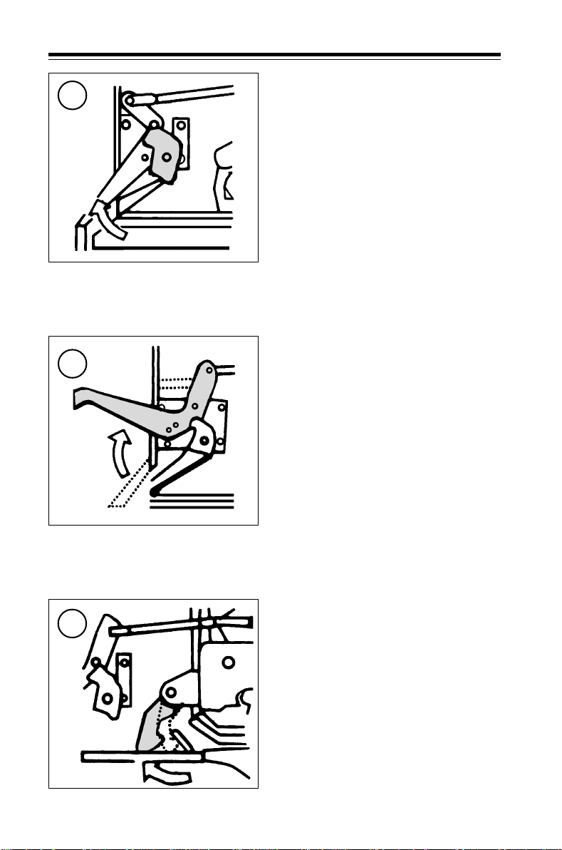
2.9 Cab tilting Know Your V ehicle
3. Hold primary locking lever ad pull
4
5
cam lever handle to release
primary locking lever from
locked condition. (sketch position
No. (4))
4. Raise primary locking lever
handle to horizontal positions.
Mounting pins of cab mounting
mechanism get released from
mounting hooks. (sketch position
No. (5))
62
5. Pull secondary locking lever to
release it from locking condition
6
and hold. Slightly raise cab to
clear secondary locking lever
from it’s hook. (sketch position
No. (6))
6. Raise cab to maximum position.
At this position cab stay locks
automatically. Cab is retained
safely in max. titled condition by
the stay. Torsion bar assists in easy
tilting of cab.
Page 65
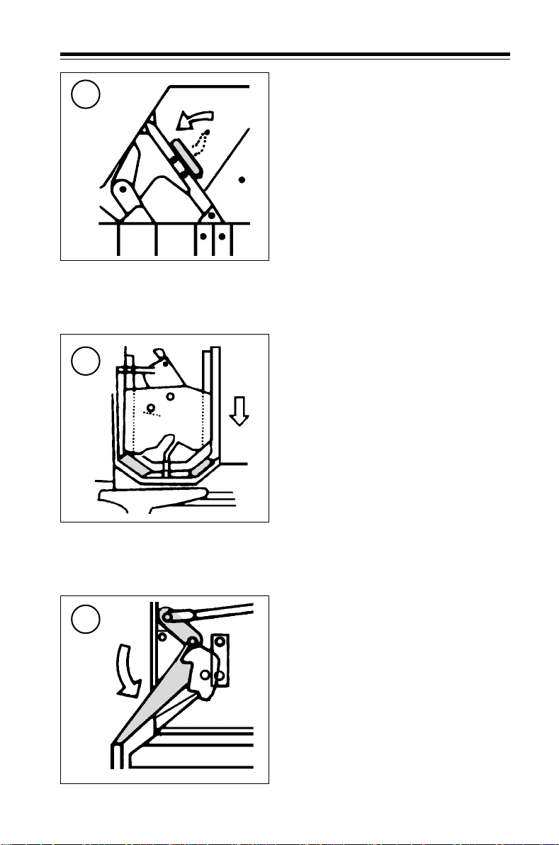
2.9 Cab tilting Know Your V ehicle
To lower the cab
7
8
1. Holding cab, press cab stay
releasing lever and slightly lower
cab. Linkage gets released from
straight position. (sketch position
No. (7))
2. Lower cab till cab gets seated on
rubber pads. Secondary locks
lever gets automatically locked in
its hook. (sketch position No. (8))
3. Push down primary locking lever
9
till it locks on the cam lever.
(sketch position No. (9))
63
Page 66
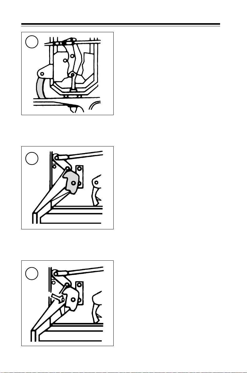
2.9 Cab tilting Know Your V ehicle
10
11
4. After locking, make sure that the
cab is fully secured with the
mounting hooks. (sketch position
No. (10))
5. Fit back padlock or bolt and nut
on primary locking lever.
(sketch position No. (11) & (12))
64
12
Page 67

2.10 Heating Know Your Vehicle
Slot A
Slot C
Heating control
Heating control (Optional)
Heating system is provided for
comfortable driving. Heating system
can be operated as per need.
The cab heat can be regulated by
controlling air flow rate of the
blower .
Three knobs A, B, C as given below
are used to operate the system.
Slot - 'A' Blower Regulator
Blower off
Blower slow speed
Blower medium speed
Blower high speed
Note : Though slot B is shown for air
at leg, slot ‘C’ to decide leg will be
open or close.
Slot B
Slot C
Slot - 'B' Air Distribution Control
Air directed towards chest
and legs
Air directed towards legs,
chest and windscreen
Air directed towards legs and
windscreen
Demist : Switch-off heater. Direct air
flow towards windscreen for a
required period.
Defrost : Switch-on heater. Direct air
flow towards windscreen for a
required period.
Slot - 'C' - Closing and opening of leg
vent
- Leg vent closed
- Leg vent open
65
Page 68

2.11 Driver seat & seat belt Know Your V ehicle
Driver seat adjustment
Lever 1 : Lever for adjusting back
rest.
1
2
3
4
Driver seat adjustment
** Precautions
Cab heating system - operates using
engine hot coolant. Hence, if engine
coolant temperature overshoots
specified limit, shut off the engine
and rectify the fault.
* * Do not leave the vehicle keeping
heater and engine in running
mode as it may cause extensive
heating inside the cab. There is
no thermostatic control in the cab
heating system to shut-off
engine, blower and heater.
Lever 2 : Lever for adjusting seat
height at rear .
Lever 3 : Lever for horizontal
movement of seat.
Lever 4 : Lever for adjusting seat
height at front.
Note : Please ensure that the seat is
locked after making necessary
adjustments.
Maintenance
1. Check hoses joints for leakage.
Tighten, if necessary.
2. Check hoses for cracks. Replace,
if required. If there is a loss of
coolant, replenish coolant
mixture in auxiliary tank.
3. If blower is not working, check
fuse, if blown, replace.
66
Page 69
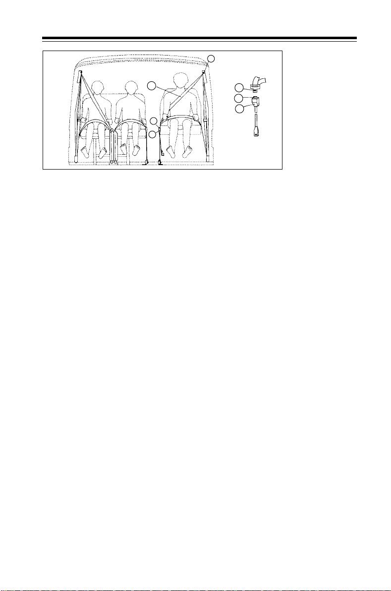
2.11 Driver seat & seat belt Know Your V ehicle
1
2
3
4
3
5
4
LHD
Seat belt arrangement
1. Anchor 2. Webbing 3. Tongue 4. Buckle 5. Release button
Seat belt
On truck versions three point belt for
driver/co-driver and lap belt for
passenger sitting in middle provided.
On bus versions, three point belt for
driver seat is provided.
Fastening the belt
Insert belt tongue into buckle. A
positive locking ‘click’ indicates
correct assembly.
Releasing the belt
Press the release button. The tongue
will be ejected clear of the locking
mechanism within the buckle.
Belt adjustment
When the vehicle is at rest, adjust
length of the belt to suit
convenience and observe that the
belt is locked.
Lap belt (middle passenger)
Adjust length of belt in the tongue
to suit convenience. Insert belt
tongue in buckle. A positive click
indicates correct assembly. To release,
press the release button. The tongue
will be ejected from the buckle.
Precautions :
● The belt is designed for use of
only one person.
● It is not intended for children
below 10 years.
● Avoid twisting the strap.
● Webbing must not be allowed to
chafe against sharp edges.
● Do not make any alterations.
● Belts that have been cut, frayed,
damaged or have been stressed
through impact, should be
replaced.
● After vehicle collision if any, belt
anchorage points should be
checked.
● An occasional wipe with warm
soapy water will maintain the
webbing in a clean condition. Do
not bleach or dye.
● Periodic inspection of the seat
belts will ensure safe and reliable
service.
● Before moving the vehicle
ensure that belt is properly
locked and beeper is off. (where
fitted).
67
Page 70

3. Driving
3.1 Starting the engine,.......................................................... 71
3.2 Driving...................................................................................72
3.3 Stopping the engine........................................................ 7 5
3.4 Special operating conditions .......................................76
3.5 Fuel economy..................................................................... 7 8
3.6 Do it yourself....................................................................... 7 9
69
Page 71
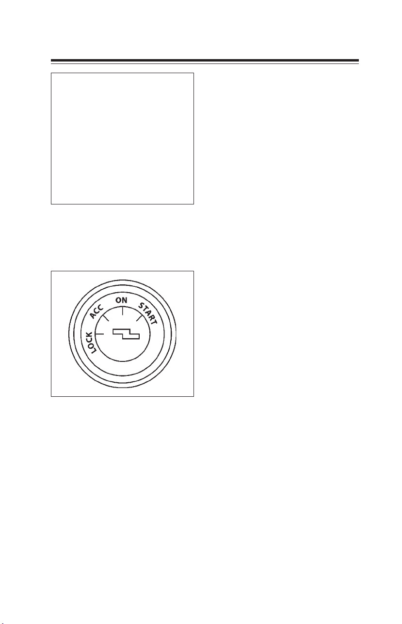
3.1 Starting the engine Driving
1. Ensure that parking brake is
applied.
2. Move gear shift lever to neutral
position.
3. Insert ignition key in steering
lock cum ignition switch.
Steering wheel will be in locked
condition. Turn the key to “ACC”
position. Steering wheel gets
unlocked, and accessories will be
ON.
Steering lock cum ignition key
4. Turn the key further to ON
position. Lamp of battery
charging indicator, low oil
pressure will come on.
5. Do not press the accelerator
pedal. Turn the key further
clockwise to “START” position
(spring loaded) to operate starter
motor. As soon as engine starts,
release ignition key so that key
can come back to ON position
and starter motor disengages.
Steering lock cum ignition switch-key
positions
6. If engine misfires and stops, wait
for 2 minutes before operating
starter motor once again. This
practice should be strictly
adhered to, otherwise it will
damage starter motor.
7. Once engine starts, lamps of
battery charging indicator and
low oil pressure should go off.
8. Allow engine to warm up - until
cooling system temperature
reaches at least 40o C.
9. Release parking brake.
10. Now the vehicle is ready to
move.
71
Page 72

3.2 Driving Driving
Engaging position for various
gears are shown on gear knob.
Change gears at appropriate
speed and do not lug the
R
2
4
engine by too early high gear
changes at low speed.
135
Gear lever knob
Driving, Gear shifting, Breaking
DRIVE SAFELY AND JUDICIOUSLY
Remember SAFETY FIRST.
Do not keep driving till you are
overcome by fatigue. The reflexes of
a tired driver are not as they should
be.
1. Before you drive, ensure that
vehicle is in a road-worthy
condition. Especially check
steering system, tyres, brakes,
clutch etc.
2. Release parking brake.
3. Depress clutch pedal fully
before shifting gears. For
smooth starting of vehicle
without jerks, synchronise
release of clutch pedal with
pressing of accelerator pedal.
4. Gear Shifting
Vehicle should be started in
first gear only.
Reverse gear should only be
engaged when vehicle has been
brought to a complete stop.
Approximate speeds for gear
change.
Speed in kmph
Gear
Standard
Gearbox
Optional
Gearbox
1st to 2nd 12 12
2nd to 3rd 23 23
3rd to 4th 37 40
4th to 5th 62 67
5. While driving, left foot must not
rest on clutch pedal. This causes
abnormal wear of clutch linings
due to clutch slippage.
6. Slowing down the vehicle
should be achieved by changing
down to lower gears.
7. Maintain a steady speed, avoid
quick acceleration and sudden
braking. High speed driving saves
you a little time but increases
fuel and oil consumption. It also
causes faster tyre wear.
72
Page 73

3.2 Driving Driving
We, therefore, recommended to
drive in fifth gear at a steady speed
of about 70 kmph. Optimum fuel
consumption is achieved at this
speed
CAUTION DURING RUNNING IN
PERIOD
During first 2,000 km. observe
following speed and load limits.
Speed
Not more than 70 kmph in top gear
and correspondingly lesser in lower
gears.
Load
Gross vehicle weight should not
exceed 2/3 of max. recommended
gross vehicle weight.
Brakes
Avoid panic braking during first
500 kms. Drive in lower gears when
negotiating steep down gradient,
thus avoiding excessive braking and
brake drum over heating.
effect. Do not ride brakes. This
will lead to over heating of brake
drums and linings resulting in
low brake efficiency.
9. Parking the vehicle
Apply parking brake. Keep
engine in low idling speed at
least for three minutes (Turbo
charged engine). Switch off
engine. Remove key from
steering lock cum ignition
switch. While parking on slopes,
place wheel chokes to prevent
vehicle rolling. Engage forward
gear if it is likely to roll in the
reverse direction or vice versa.
8. Application of brakes
Brake application should be
gradual to avoid fast wear of
brake linings, brake drums and
tyres. Brake should not be
applied too violently on a
slippery road, since the vehicle
may then start skidding.
When driving down a long steep
gradient, reduce vehicle speed
by shifting to lower gear.
Engine will provide a braking
73
Page 74

3.2 Driving Driving
Since exhaust opening is restricted,
road wheels will drive engine, which
will act as a compressor (resistor),
thus retarding vehicle speed.
Use of engine exhaust brake results
in increased life of brake linings,
brake drums & tyres.
Isolator switch (Exhaust brake)
Hand brake valve
A. Brake released
B. Brake applied
A to B Gradual application
Hand brake system
Hand brake is integral with spring
brake actuator on rear axle. Spring
brake chamber piston ram acts
directly on push rod assembly of
brake chamber.
Engine exhaust brake
Exhaust brake operation is coupled
with service brake. Whenever brake
pedal is depressed for applying
brakes, exhaust brake also gets
applied and indicator lamp (E) comes
ON instrument panel.
Stop light switch provides signals both
for rear tail lamps as well as for
exhaust brake solenoid valve.
In certain situations like starting of
vehicle on an upgradient,
simultaneous acceleration and partial
braking of vehicle are required.
Isolator switch can be used to cut off
air supply to exhaust brake air
cylinder, by putting it in off
(disengaged) position. Isolator switch
should be put ON (engaged), as soon
as isolation requirement is over.
Solenoid valve opens, allowing
compressed air to flow to exhaust
brake air cylinder, thus operating
exhaust brake butterfly valve.
74
Page 75

3.3 Stopping the engine Driving
Operating instructions
1. Ensure air pressure in the system
is above 5 bar .
2. Change to lower gear
appropriate to road conditions.
Exhaust brake is very effective
below 40 kmph speed.
3. Do not depress clutch as this
would render exhaust brake
ineffective.
4. Press brake pedal fully when
vehicle is to be brought to a
stop.
Lubricating exhaust brake
linkages
1. Every 9,000 km. a few drops of
oil should be applied to ball pins
of outer linkages and friction
surface.
2. Butterfly valve shaft, which is
made of heat resistant material,
should not be lubricated,
since the lube oil would cause
seizing of the butterfly valve in
its housing.
shut off valve and fuel supply is
cut off. Engine will stop. This shut
off timer is aborted in case you
turn ignition key again to ON
position within 5 seconds.
5. Turn the key to “lock” position.
6. Take out key from steering lock
cum ignition switch. Slightly turn
steering wheel clockwise or anti
clockwise (max. 180o), till click
sound is heard, to make sure that
steering wheel is locked.
Stopping the engine
After parking the vehicle in safe
place.
1. Release accelerator pedal.
2. Move gear shift lever to neutral
position.
3. Apply parking brake.
4. Turn ignition key to ACC
position. A timer will switch on
fuel stop solenoid for about 5
seconds which operates fuel
75
Page 76

3.4 Special operating conditions Driving
Flame start system (BERU):
Flame start system is provided for
convenient starting at cold
conditions by heating the intake air
by means of burning the diesel in air
intake manifold.
● Pre-glow time of just 20~45
seconds
● Trouble-free starting even at
BERU heater controller
T emperature transducer
Flame glow plug
low temperatures
● Post glow (after starting the
engine) time of up to 3 minutes
The flame start control unit controls
the supply of current to the indicator
light, flame glow plugs and solenoid
valve. It evaluates the signals from
starter motor in Ignition ON position
via Temperature transducer (BERU)
in alternator running condition.
The pre-glow phase commences
when the ignition is switched on at
temperature below the system stop
temperature.
The indicator light comes on steady
and power is fed to flame glow plug.
Once the pre – glow time has passed
the indicator lights starts to flash. This
indicates to the operator that the
engine can be started. Power
continues to be supplied to the
flame glow plugs. If the engine is not
started during this period, the flame
start control unit switches off the
flame glow plugs and the indicator
light.
If the vehicle is started during ready
to start period, then the flame start
control unit activates the solenoid
valve. The fuel then flows through
the open solenoid valve, across the
76
Page 77

3.4 Special operating conditions Driving
hot heater rod of the flame glow
plug, evaporates and ignites.
The post heating operation begins
once the start procedure has ended.
The duration is determined by the
engine temperature (coolant water)
when the post heating commences.
Power continues to be supplied to
the flame glow plugs, the solenoid
valve remain open and indicator light
goes off.
If the start procedure is unsuccessful,
then the solenoid valve and flame
glow plugs are shut off, the ignition
must be switched off before
attempting to restart. Where
temperature exceeds the system
stop temperature, the indicator light
immediately starts flashing to
indicate start ready, after the ignition
has been switched on.
No power is supplied to the flame
glow plug and the solenoid valve.
77
Page 78

3.5 Fuel economy Driving
Fuel Economy
a. Drive smoothly, accelerate
gradually, avoid harsh
acceleration.
b. Best fuel consumption is
obtained at low engine speeds
in the highest possible gear
without labouring the engine.
c. Driving with accelerator pedal
fully depressed means using
excessive fuel.
d. Do not allow the engine to
labour by too early high gear
changes. Change to lower gear
when engine no longer runs
smoothly.
e. Switch ‘OFF’ engine when
stopping for long duration of
time.
f. Do not ride clutch. Do not
use clutch pedal as foot rest.
g. Do not allow leakage or spillage
of diesel.
h. Always drive in correct gears.
i. Do not over load the vehicle.
j. Maintain correct tyre pressure.
k. Always keep vehicle and engine
in good condition.
Operation in hilly terrains
In hilly terrain and where the
atmosphere is very humid, following
precautions should be taken.
descending. Make maximum use of
exhaust brake while descending.
With a little pressing of brake pedal,
exhaust brake first comes into action.
This will relieve driver of fatigue and
will increase the life of tyres, brake
linings and brake drums.
Note :
Diesel and clutch fluid, both being
hygroscopic, absorb moisture from
atmosphere.
● Drain air tanks every day to
remove water.
● Drain water from fuel water
separator.
● Vehicle should be greased every
day to prevent formation of rust
on the exposed moving
surfaces. Servicing and
maintenance should be done as
specified.
● Use same gear selection while
ascending and descending the
same slope.
Caution : Operating engine beyond
high idle speed can cause severe
engine damage. When descending a
steep gradient, use a combination of
transmission gears and exhaust
brake or service brake to control
vehicle and engine speed.
● Use lower gears and brake
cautiously on wet and slippery
roads.
Ensure that steering linkages and
brakes are in order and proper gears
are used during climbing and
78
Page 79

4. Maintenance Procedure
4.1 Air intake system ...........................................................83
4.2 Fuel system......................................................................85
4.3 Lubrication system ........................................................87
4.4 Cooling system...............................................................89
4.5 Clutch ................................................................................92
4.6 Gearbox............................................................................. 94
4.7 Propeller shaft ................................................................ 95
4.8 Front axle & rear axle.................................................... 96
4.9 Power steering...............................................................97
4.10 Brake system................................................................101
4.11 Springs............................................................................ 114
4.12 Centre flap....................................................................115
4.13 Tilt cab ............................................................................ 116
4.14 Wheels and tyres ........................................................ 117
4.15 Electricals....................................................................... 121
4.16 Preservative treatment............................................. 128
4.17 Care and cleaning ...................................................... 131
81
Page 80
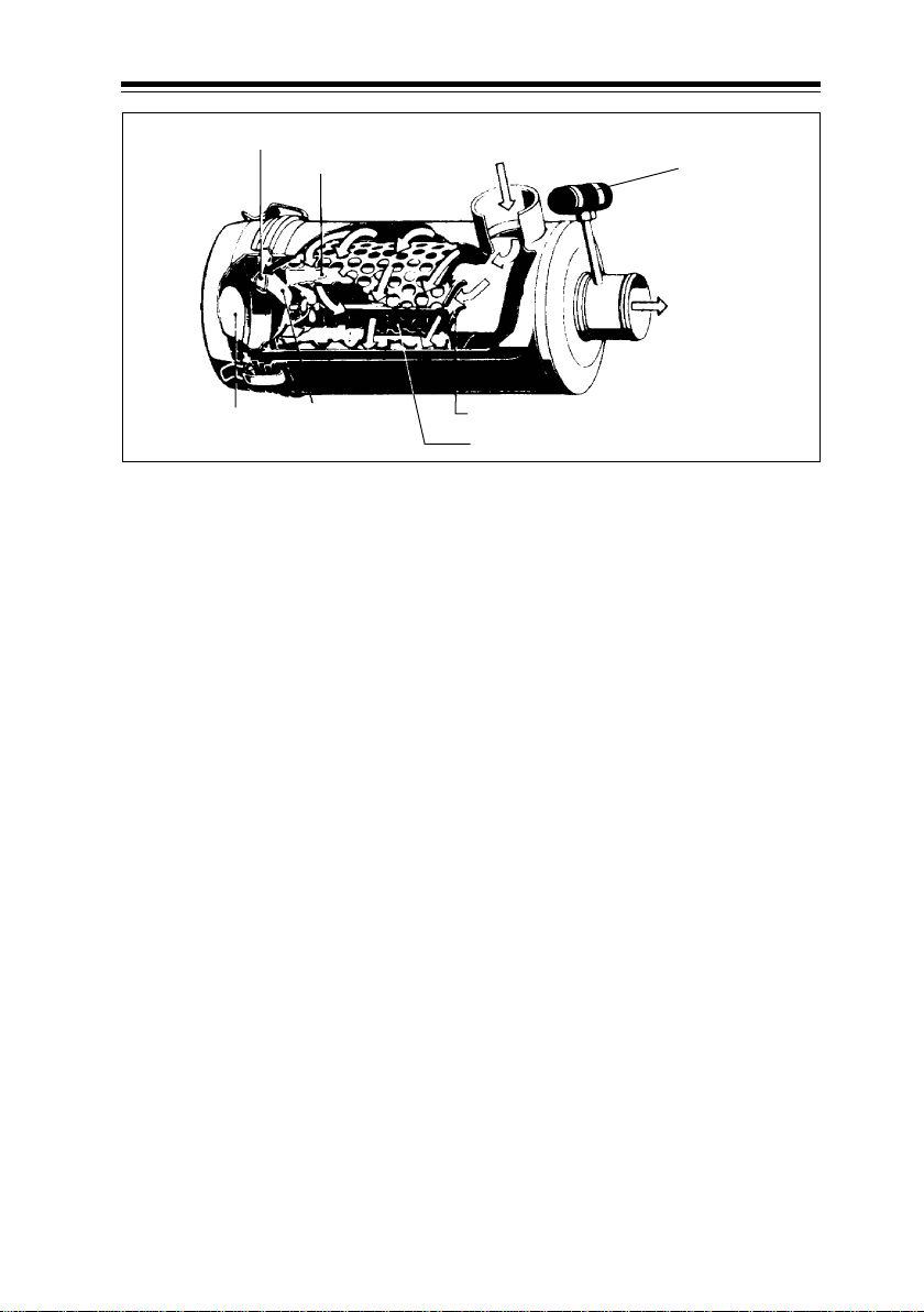
4.1 Air intake system Maintenance
Slit for dust
separation
Dust bowl
Primary
cartridge
Plastic cover
Atmospheric air
from intake duct
Schematic details of dry type air filter
Maintenance of dry type air filter
(Vehicle with Euro II engine)
Dry type air filter with an inbuilt
cyclonic vane type pre-cleaner is
fitted. For vehicles operating under
normal conditions evacuator valve
(of air filter) is required to be
checked once every 2,000 km. This
should be done more often, if
vehicle operates in dusty conditions,
viz. off highway operation, mining
areas, construction sites, etc.
While reassembling, care must be
taken to ensure that evacuator valve
is assembled in the bottom most
position and slit opening is pointing
towards ground.
When service indicator glows, on
instrument panel. Clean air filter
housing and primary cartridge.
Electric
service
indicator
Air to
turbo
charger
Cyclonic pre-cleaner
Secondary cartridge
Replacement of air filter primary
cartridge
a) Remove cover of air filter.
b) Remove primary cartridge
(element).
c) Clean air filter housing, air ducts.
d) Replace old primary cartridge by
new one.
e) Fit the cover. On starting the
engine, if service indicator on the
instrument cluster continues to
blink take your vehicle to nearest
Ta ta authorised workshop.
f) Do not clean secondary
cartridge. Replace it after three
changes of primary cartridge or
after 2 years, whichever is earlier.
83
Page 81
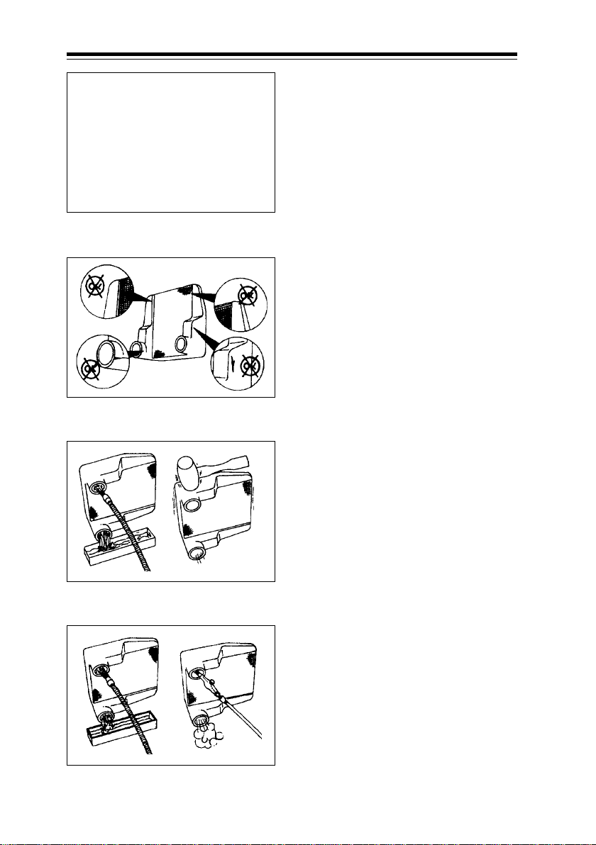
4.1 Air intake system Maintenance
Charge air cooler (CAC)
(with Euro II engine)
Inspection
If engine experiences a turbocharger
failure or any other occasion where
oil or debris has entered into CAC,
the CAC must be cleaned.
Charge air cooler
Charge air cooler
Cleaning with solvent
Remove CAC from vehicle.
Visually inspect CAC for cracks, holes
and damage.
Inspect tubes, fins and w elds f or tear,
breakage or other damage.
Cleaning
Flush CAC internally first with
trichloro ethane (solvent) in the
opposite direction of normal air flow.
Shake the CAC and lightly tap on the
end tanks with a rubber mallet to
dislodge trapped debris.
Caution : Do not use caustic
cleaners to clean CAC. Damage to
CAC will result.
After the CAC has been thoroughly
cleaned of all oil and debris with
solvent, wash CAC internally with
industrial soap solution to remove
remaining solvent. Rinse thoroughly
with clean water .
Cleaning with hot water/compress air
84
Blow compressed air into the CAC in
the opposite direction of normal air
flow until the CAC is dry internally.
Page 82
4.2 Fuel system Maintenance
Fuel water separator cum
primer:-
It is fitted in between fuel tank and
FIP.
It separates water particles in fuel.
Fuel passes over funnel like cone in
water separator and water being
heavier than fuel, so water gets
collected at the bottom of the
Fuel water separator cum primer
bowl.
To remove water from the bowl
loose the primer then loose the
drain plug ,
Water starts dropping from drain
plug.
Once water is completely drained
from the water separator. Tighten
the drain plug and primer.
It is recommended that water in the
separator be drained at least once
a week.
Fuel filter change
1
2
1. Bleeding screw on banjo bolt
2. Drain plugs
1. Remove filter bowls by
removing two bolts given on
filter cover.
2. Clean the bowls.
3. Fit new elements in bowls
a) Felt type element in primary
filter bowl.
b) Coil type micro element in
secondary filter bowl.
4. Replace O - rings on filter cover.
5. Assemble primary & secondary
filter bowls to the cover. Tighten
bolts to 2 mkg torque.
6. Fill diesel in filter bowls by
operating feed pump primer .
7. Bleed fuel system and start
engine.
85
Page 83

4.2 Fuel system Maintenance
If performance of engine is affected
due to presence of air in fuel system
(commonly known as air lock), it can
be rectified by bleeding fuel system.
Fuel system bleeding
1. Ensure no leakage in fuel line.
2. Bleeding air in fuel line upto filter
- Loosen outlet banjo of fuel
filter.
- Prime the circuit by using
hand primer.
- Tighten banjo after
completely bleeding air.
3. Bleeding air after FIP
- Loosen overflow banjo on FIP.
This ensures FIP is filled with
fuel.
- Prime the circuit by using
hand primer.
- Tighten overflow banjo after
completely bleeding air.
4. Crank engine for few seconds. If
engine still does not start
proceed to next step.
5. Remove cylinder head cover &
loosen high pressure line cap
nuts of all cylinders.
6. Crank engine till fuel coming out
of high pressure lines is free
from air. Tighten high pressure
line cap nuts.
7. Start the engine.
86
Page 84
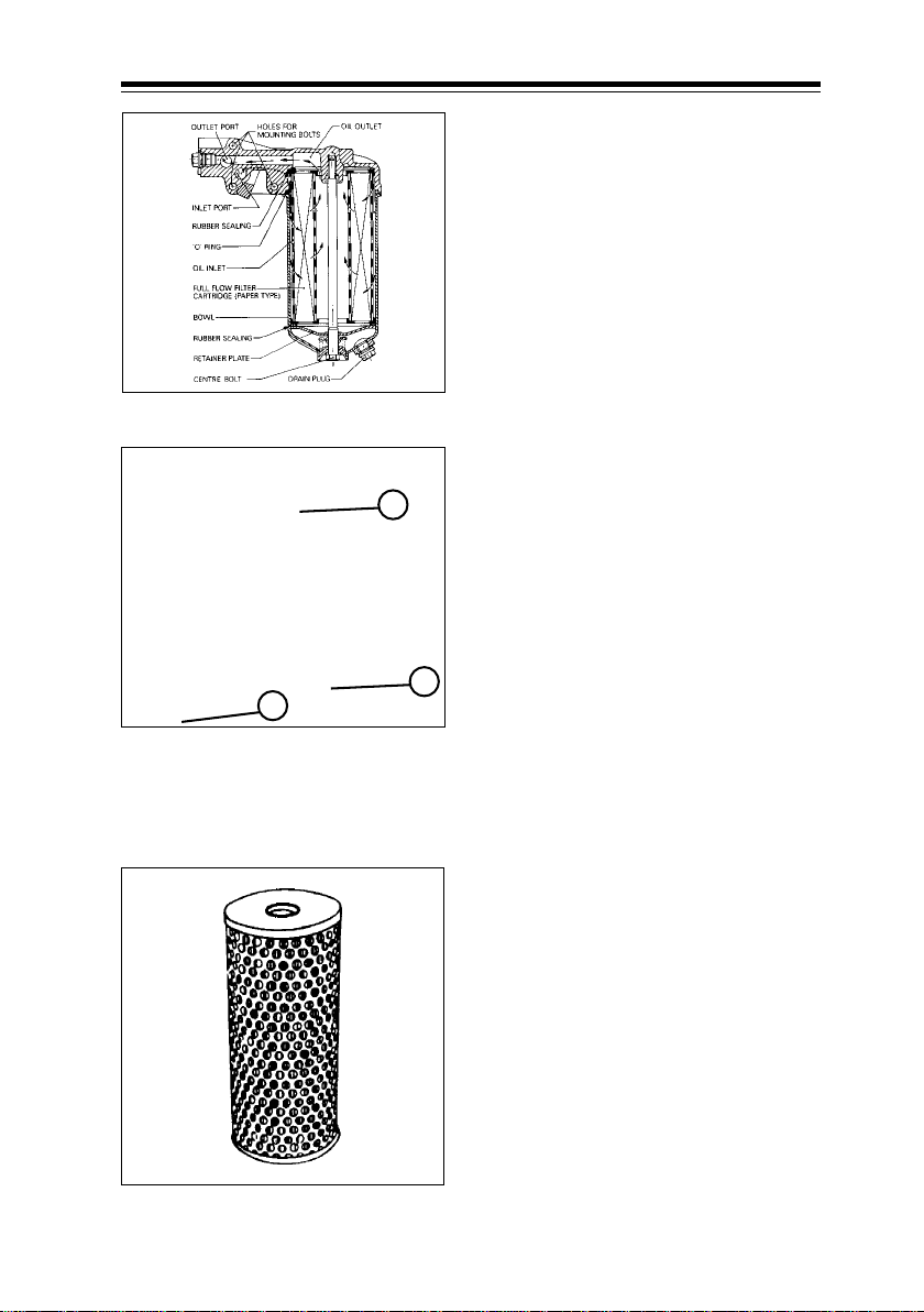
4.3 Lubrication system Maintenance
Changing engine oil / oil filter
Engine oil should be drained while it
is still hot.
a. Unscrew sump drain plug and
allow oil to drain out for
20 minutes.
b. Unscrew drain plug of oil filter,
drain out oil and refit drain plug.
c. Unscrew centre bolt and
Full flow engine oil filter assembly
3
2
1
1. Drain plug engine oil sump
2. Drain plug oil filter
3. Filler plug oil filter
remove oil filter bowl, clean
centre bolt.
d. Clean the bowl thoroughly and
replace with a new genuine
filter cartridge.
e. Remove old ‘O’ ring in cover and
install a new O’ ring.
f. During reassembly, first fill filter
bowl with 1 litre of engine oil
and thereafter reassemble filter
bowl on top cover . Pour another
1.5 litres of engine oil through
the filler plug opening in the
cover & then tighten filler plug
with a new sealing washer.
Oil filter cartridge
This is done to ensure that oil
immediately flows to bearings
and attains correct pressure,
when engine is started. If this
instruction is ignored, bearings
may get damaged.
Oil filter must be kept clean to
protect engine components
from rapid wear due to abrasion.
g. Oil filter centre bolt should be
tightened to 4 mkg torque.
87
Page 85

4.3 Lubrication system Maintenance
h. Clean the drain plug of oil sump
and refit with a new sealing
washer, if necessary. Tighten
drain plug to 4 to 6 mkg torque.
i. Fill in recommended quantity of
engine oil in sump.
j. Start engine and allow it to run for
a few minutes and stop the engine.
Engine oil dip stick
A
Engine oil dipstick
A. Minimum level
B . Maximum level
k. After 20 minutes, check level of
oil on dipstick. It should be at
upper mark. If not, top-up. When
checking oil level, vehicle should
be parked on level ground.
CAUTION
Make sure that only genuine oil filter
cartridge is used.
i. Do not use filter with inferior
filtering material which cannot
properly filter the engine oil.
ii. Do not use filter with improper
dimensions which cannot
prevent filtered oil getting
B
mixed with unfiltered oil.
Since it is extremely difficult to
distinguish between genuine and
non-genuine filter cartridges, obtain
these only from Tata authorised
workshop.
Discard used oil filter cartridge.
Filter cartridge should not be
cleaned or reused.
88
Change Engine Oil after every
18000 kms or earlier depending on
the type of operation.
Use only recommended engine oil
conforming to SAE 0W-40 APICH4 &
MB228.3 specifications.
Page 86
4.4 Cooling system Maintenance
Cooling system
A transparent radiator auxiliary tank
is fitted between cabin rear wall and
load body on LPT 613 vehicles. On
LP 613 this is fitted behind driver
seat. Maximum & minimum levels
indicated on the body. It is fitted
with two identical caps with
pressure cum vacuum relief valve
Radiator auxiliary tank filler neck (LP)
Radiator auxiliary tank filler neck
(LPT)
Radiator drain plug
having 0.5 bar pressure setting.
Always top up coolant only through
filler neck. Top cap should not be
disturbed.
Procedure for filling when the
system is empty.
1. Ensure no water in vent pipes,
drain vent pipes while draining/
refilling.
2. Fill coolant mixture through
auxiliary tank filler neck.
3. Run engine for a few minutes
and top up coolant mixture, if
required.
Add recommended coolant to
water in ratio 1:1. If coolant starts
boiling, it may be on account of :
i. Less coolant or dirt/scale having
accumulated inside coolant
passages, especially in radiator
core.
ii. Choking of radiator air passages
due to foreign material or
damaged radiator fins.
iii. Loss of coolant by evaporation
and leakage through defective
auxiliary tank caps.
iv. Loose water pump drive belt.
v. Coolant leakage.
89
Page 87

4.4 Cooling system Maintenance
Always use genuine auxiliary tank
cap. A proper cap firmly fitted
maintains pressure in the cooling
system and makes engine more
efficient by permitting a slightly
higher operating temperature.
Vacuum created in the system is
relieved by a valve provided in the
cap. Descale and clean cooling
system regularly.
Cleaning of cooling system.
This should be done at every
80,000 km or every two years
whichever is earlier.
While cleaning, the system is to be
totally drained out. Coolant from vent
pipes is to be drained out by
disconnecting these pipes from
auxiliary tank end side.
Fill the system with industrial soap
solution through filler cap in auxiliary
tank.
Wait for 2 to 3 minutes to allow air
to be vented and add solution to
bring the level to the top.
Again operate the engine for 5 mins.
with water temperature above 800 C
at maximum engine speed.
Stop engine and drain water.
If water drained is still dirty, system
must be flushed again until water
drained out is clean.
Use a mixture of 50% water and 50%
ethylene glycol non-amino base
antifreeze to fill cooling system.
Fill the system slowly to prevent air
locks. During filling air must be
vented from the engine and radiator .
Wait for 2 to 3 minutes to allow the
air to be vented and then add
mixture to bring coolant level to the
top.
Install filler cap. Operate engine until
it reaches a temperature of 800 C, and
check for coolant leaks.
Wait until the coolant temperature
reaches below 500 C. Check coolant
level again to make sure the system
is full of coolant.
Do not install filler cap.
Operate engine for 5 mins. with the
flushing solution temperature above
800 C. at maximum engine speed.
Stop engine and drain soap solution.
Fill system with clean water. Be sure
to vent the engine for complete
filling.
Do not install filler cap.
90
Page 88

4.4 Cooling system Maintenance
1
2
Fan belt tension adjustment
1,2.Idler pulley flange nuts
3. Tensioner rod mounting nut
A. Check nut
B . Adjusting nut
A
B
1. Loosen idler pulley flange nuts
1, 2 and the tensioner rod
mounting nut 3 as shown in the
picture, to release the fan idler
pulley arrangement.
2. Loosen the check nut A and
Fan belt tension adjustment
3
rotate adjusting nut B to get the
desired tension of fan belt.
Slackness should be approx.
20 mm at the centre of fan belt
drive, when checked by thumb
push.
3. Tighten check nut A without
disturbing the position of
adjusting nut B..
4. Without disturbing the
arrangement, retighten nuts 1, 2
& 3 as explained above.
5. Recheck belt tension and
confirm.
91
Page 89
4.5 Clutch Maintenance
A=126mm
Stopper screw
Master
Check nut
Clutch pedal
Clutch pedal height
Clutch pedal stopper screw
cylinder
Clutch pedal adjustment
Hydraulically operated clutch has
been fitted on this vehicle.
Clutch pedal height adjustment is
required only in case of component
repairs/overhaul etc. Adjustment is
not required during normal
maintenance.
1. Loosen check nut on clutch
master cylinder push rod.
2. Adjust the distance of 126 mm
between master cylinder flange
face and the fork hole centre as
shown in the figure.
3. Tighten push rod check nuts of
master cylinder without
disturbing adjusted length.
4. Adjust clutch pedal free play
with the help of stopper screw
as shown in figure. Free play at
clutch pedal should be between
15 - 20 mm.
92
5. Operate clutch pedal a few
times to ensure desired clutch
pedal free play.
6. Apply synthetic grease at all
rotary joints.
Clutch pedal height adjustment &
free play adjustment is needed to be
done at Tata authorised workshop
only.
Page 90
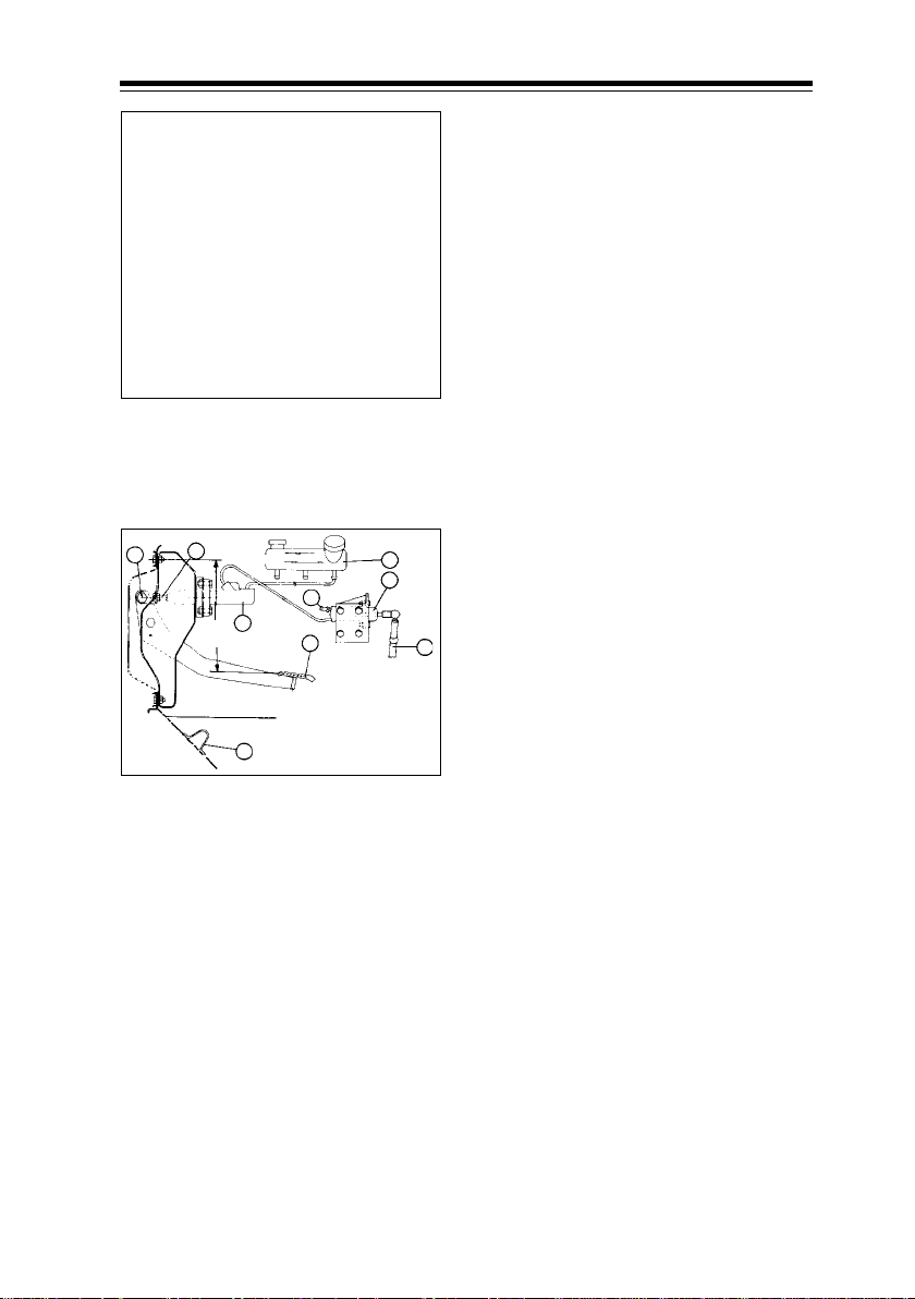
4.5 Clutch Maintenance
Clutch fluid filling and bleeding
Procedure for bleeding the system
given below :
i. Remove filler cap and fill the
clutch fluid container with fresh
brake fluid.
ii. Remove dust cap from slave
cylinder bleed screw and clean
it thoroughly. Attach bleed tube
to the bleed screw and place
Filling clutch fluid
other end of the tube in a clean
glass jar containing sufficient
brake fluid to submerge the end
of tube.
8
2
7
5
220mmapprox.
1
9
4
6
3
Schematic layout of clutch actuation
mechanism
1. Clutch Pedal
2. Adjusting pin
3. Clutch release fork
4. Clutch fluid container
5. Clutch master cylinder
6. Clutch slave cylinder
7. Bleeding nipple
8. Master cylinder push rod
9. Clutch pedal stop
iii. Pump clutch pedal twice/thrice
slowly throughout its stroke and
by holding the pedal pressed,
loosen bleed screw and watch
air bubbles in glass jar.
iv. Retighten bleed screw and
repeat the same operation until
air bubbles cease to appear
allowing only fluid to flow.
v. Replace dust cap on bleed
screw without fail.
93
Page 91
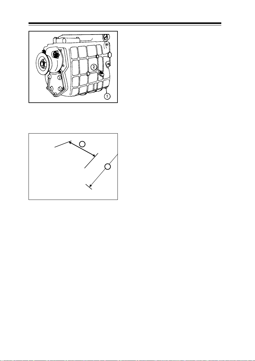
4.6 Gearbox Maintenance
Gear box oil checking
Check level of gear box oil. Top up if
necessary.
Gear box oil change
Drain while hot.
Fill the gear box with new oil.
Capacity : 5.2 Litres
: 5.8 Litres
Recommended oil
Gear box (GBS - 40)
1. Oil drain plug
2. Oil level plug
A
B
Remote gear shifting arrangement
Grade SYN gear EP 75 W 90 GL 4 Gulf
grade.
Dimension A
Link rod adjustment
Either increasing or decreasing the
length or link rod assembly can
adjust dimension A. Loosen lock nuts
on both sides of connecting tube &
adjust the length by turning
connecting tube with the help of DE
spanner clockwise / anti clockwise.
When desired dimension is achieved,
tighten lock nuts on both sides & recheck dimension A. The adjustment
needs to be carried out in installed
condition of link rod.
Dimension B
Turning tube adjustment
This adjustment is to be carried out
after disconnecting ball joint from
gearshift lever. Loosen the lock nut
from connecting flange & rotate ball
joint clockwise /anti clockwise to
obtain desired dimension. Tighten
the lock nut. Assemble ball joint nut.
Re-check dimension of turning tube
assembly (Dimension B).
Link measurement (in mm)
Drive A B
RHD 330 ± 1.5 1000 ± 2
LHD 350 ± 1.5 986 ± 2
94
Page 92

4.7 Propeller shaft Maintenance
Propeller shaft
Propeller shaft, U-joint cross bearing
and sliding yoke should be regularly
greased. Failure to do so may result
in rapid wear and tear of the bearings
and centre bearing mountings.
Periodically check and if necessary,
tighten mountings of centre bearing
bracket to 8 mkg torque.
Propeller shaft centre beaming
U Joint yoke
When disconnecting propeller shaft,
care must be taken to ensure that
arrow marks on rear propeller shaft
and sliding yoke are aligned during
reassembly. Tighten coupling flange
bolts to 7 mkg torque. When fitting
propeller shafts ensure all ‘U’-joint
yokes are in one plane. In case of
undue vibrations noticed on
propeller shafts, take necessary
corrective action.
95
Page 93

4.8 Front axle & rear axle Maintenance
Hub grease for front & rear hubs to be
changed at every 36000 kms.
2
1
Hub greasing and adjustment
Remove front and rear wheel hubs.
Dismantle and clean bearing and
other components. Re-pack with
bearing grease.
Front hub : 250 gm/ hub
Rear axle
1. Oil drain plug
2. Oil level plug
Rear axle oil level checking
Check level of rear axle oil. Top up if
necessary.
Rear axle oil change
Drain while hot
Fill the rear axle with new oil.
Capacity : 2.75 litres
Recommended oil
Grade APIGL 5 SAE 85W-140 with
7% Anglamol-6043 by weight.
Change rear axle oil first at 9000 km,
then at 36,000 km and thereafter at
every 36,000 km.
Check front & rear hub play at every
9000 kms & adjust, if necessary .
Rear hub : 450 gm / hub
Grade - Multi purpose grease No. 2
Adjust hub bearing play .
Front hub : 0.01 / 0.06 mm
Rear hub : 0.04 / 0.1 mm
Tubular spacer with shims provided
in between bearings for front and
rear hubs to control hub play .
This operation is needed to be carried
out at Tata authorised workshops
only.
Front hub
Remove front hub cap, fill with ¾th
full wheel bearing grease and refit at
every 9000 kms.
96
Page 94

4.9 Power steering Maintenance
Then turn steering wheel several
times from lock to lock so that air
escapes from the system. Keep
watching oil level. Add oil
immediately when oil level drops.
Keep adding oil till the level remains
at upper mark on dipstick and air
bubbles are no longer visible in oil
Power steering tank
OIL FILLING AND BLEEDING
Filling oil in steering tank
Steering gear and pump are filled
through filler neck on oil tank. For
initial filling and for oil changes it will
be of advantage to remove the tank
cover and to add hydraulic oil upto
edge of tank. Engine can then be
cranked with starter motor for a while
(not more than 10 seconds at a
stretch) to fill entire hydraulic system
with oil. Since oil level in tank will
drop rapidly, keep adding oil to avoid
pump sucking air.
tank when steering wheel is turned.
If above instructions are observed, oil
level in tank should not raise by more
than approx. 1-2 cm when engine is
shut off.
Shut off engine and lower front axle.
Oil level check-up when engine
stopped
Add enough oil in tank until oil level
is approx. 1-2 cm above upper mark.
Start engine and run it at idling
speed. Check oil level in dipstick. Oil
level should be between minimum
and maximum levels.
Bleeding the steering system
When steering gear is filled to the
extent that short cranking of engine
will not cause oil level to drop below
top mark on oil dipstick, engine can
be started.
Jack up front axle, start engine, run
at idle speed for some time, thus
allowing air to escape from the
system. Oil level must be watched
during this process. Oil must be
topped up immediately if the level
drops.
97
Page 95

4.9 Power steering Maintenance
Oil level check-up with the
engine running
With engine running, oil level will
drop slightly, since oil requires a
pressure of appox. 2-4 bar to
overcome flow resistance when
B
A
Power steering tank
A. Bottom level
B. To p level
flowing through the system. Add
enough oil to keep oil at upper mark.
Stop engine. Oil level should not
raise more than 1-2 cm. A higher oil
level indicates that there is air in the
system.
Filter change
a. Unscrew closing plug from cover
of oil tank and remove tank cover.
b. Pull out used filter cartridge.
When pulling out, keep bore of
filter cartridge closed so that no
dirty oil could flow back into tank.
c. Lubricate filter carrier and insert
new filter cartridge with metal
collar in upward direction.
98
d. Crank engine for a short period
with starter motor, so that oil level
will drop. Then bleed the system.
Replace oil/oil filter at every
80,000 kms. Bleed the system and
check performance with test
equipment.
Page 96
4.9 Power steering Maintenance
Power steering pump belt
tension adjustment
Checking and adjustment of steering
pump belt tension.
a. Loosen bolt holding upper
mounting of steering pump to
the clamping piece.
b. Loosen steering pump pivot pin
nut.
c. Loosen the locknut & adjust belt
tension by rotating the adjusting
Checking power steering pump belt
tension
nut.
d. Check belt tension. Belt tension
is correct, if it can be depressed
by 20 mm with thumb pressure
applied in the middle of its
length.
2
4
1. Lock nut
2. Adjusting nut
3. Clamping bolt
4. Clamping piece
e. Tighten clamping piece bolt, lock
1
3
nut and pivot pin nut for locking
the pump in position.
Power steering linkages
In case of excessive free play, check
steering linkages for looseness and
get the defect rectified immediately.
Periodical inspection of steering
linkages is essential for driving safety.
99
Page 97

4.9 Power steering Maintenance
Sector shaft play adjustment
If play is noticed on drop arm or input
A
B
Sector shaft play adjustment
A. Sealing nut
B. Adjuster screw
shaft of steering gear box, it is to be
adjusted as given below :
● Bring steering wheel to SAP
(Straight Ahead Position).
● Sealing nut is to be loosened in
anticlockwise direction by
holding adjuster screw in place
with a screw driver.
● Rotate adjuster screw with
screwdriver in anticlockwise and
check for play on drop arm. Play
will increase.
● Again rotate adjuster screw in
clockwise direction till the play
disappears on drop arm, holding
the sealing nut in place.
● Turn adjuster screw clockwise
another half turn. Hold it in place
with a screw driver and lock
sealing nut.
100
T orque f or sealing nut is 70 Nm.
This adjustment is usually required
after a coverage of 100,000 kms.
Page 98

4.10 Brake system Maintenance
S Cam full air brakes
S cam brakes are fully air operated
brakes. Brake actuators at front and
rear axles are externally mounted
outside the foundation brake
assemblies.
Air is fed to brake actuators through
dual brake valve (Operated by brake
pedal), proportional to braking
requirements.
Push-rods of brake actuators act on
slack adjusters, which convert linear
motion into circular motion of cam
shaft. S-shaped cam portion of shaft
expands brake shoes against drums,
thus applying brakes.
S cam is of equal displacement
design, resulting in equal wear of
leading and trailing shoes.
Brake system provides safe and
reliable braking. Brake circuit
consisting of various pneumatic
components is shown in schematic
layout.
Service brakes consist of two
separate circuits. One for front
wheels and the other for rear wheels.
In the unlikely event of failure of any
one circuit, other circuit remains still
operative and guarantees a certain
degree of braking for the vehicle.
One of the auxiliary outlet of system
protection valve is connected
through a graduated hand brake
valve to spring brake chamber
portion, integral with rear brake
actuator.
air pressure, thus releasing parking
brake. For parking / emergency
braking, hand brake valve is operated
for depleting air to atmosphere, thus
applying parking brakes.
Second auxiliary outlet of system
protection valve is connected to
exhaust brake air cylinder through
exhaust brake solenoid valve which
is coupled with service brake pedal
operation through stop light switch.
Exhaust brake isolator switch is
provided on instrument panel which
can be used to cut off exhaust brake,
isolating exhaust brake whenever
required e.g. while starting the
vehicle on steep up gradient.
An air dryer cum unloader valve is
fitted between air compressor and
system protection valve alongwith
purge tank. Air dryer ensures clean
and dry air in the brake system,
resulting in enhanced life of brake
valves.
Note :
Do not attempt to clean air dryer
desiccant cartridge and filter.
Replace desiccant cartridge and filter
after every 2 years.
To conduct brake system routine
service check - I prescribed at every
18,000 km and routine checks - II
prescribes at every 36,000 km
contact nearest Tata authorised
workshop.
Procedure for these checks
explained in pages 110-112.
During normal running, inside springs
are kept in compressed condition by
101
Page 99
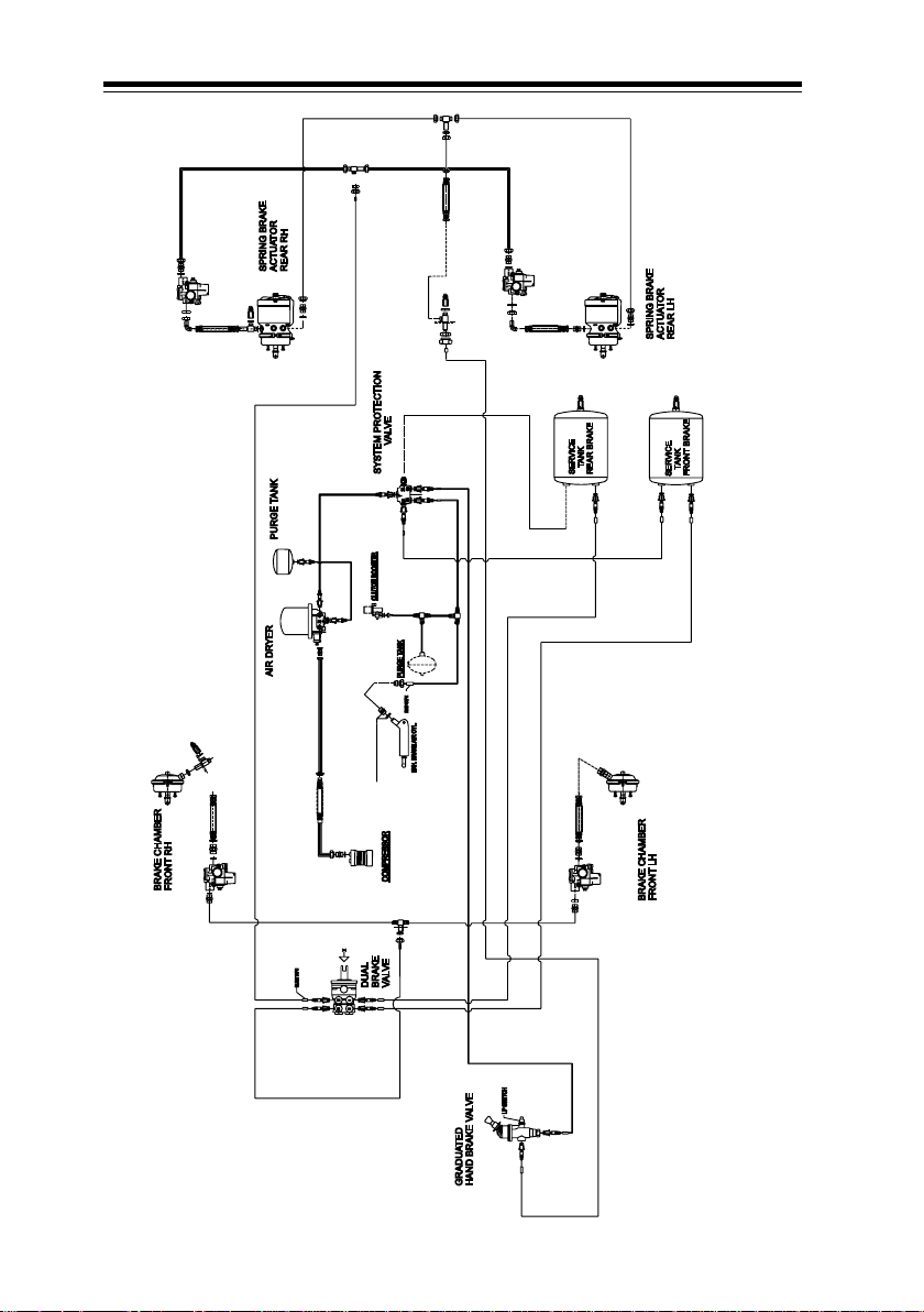
4.10 Brake system Maintenance
102
AIR BRAKE SYSTEM WITH ABS (IF FITTED)
Page 100
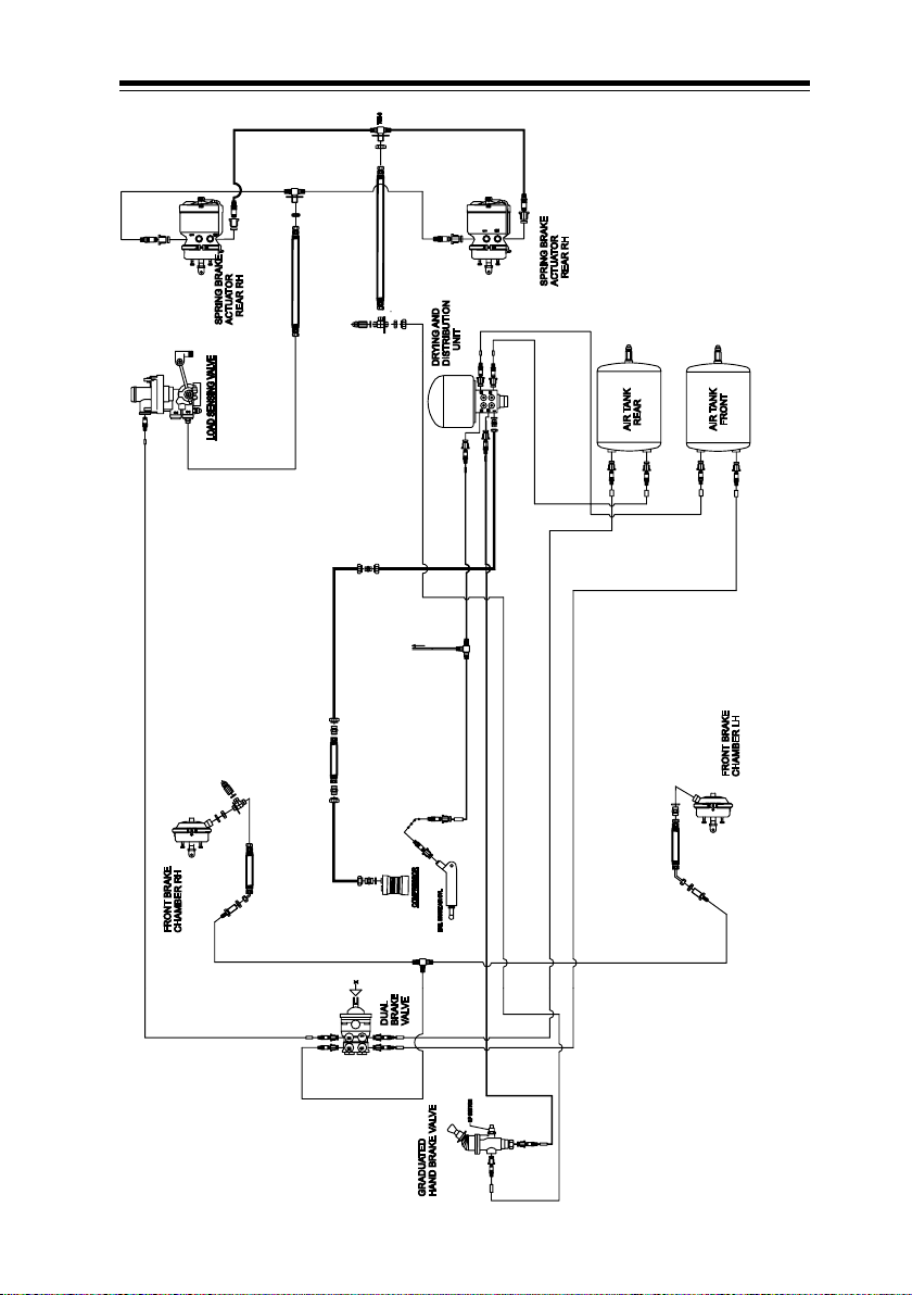
4.10 Brake system Maintenance
103
SCHEMATIC LAYOUT OF DUAL CIRCUIT FULL AIR S-CAM BRAKES WITH LCRV
 Loading...