

Page 1
TM
POWER TRACE
INSTRUCTION MANUAL PTL610
TASCO, INC.
Page 2

32
WHY THE POWER TRACETM POLYSIGTM
COMPOSITE SIGNAL IS IMPORTANT
Many circuit tracers rely on a single transmitter frequency for tracing.
This means that any noise in that frequency range will be received as
a signal, causing confusion and possibly indicating the wrong breaker.
By using the Polysig
TM
composite signal as well as a unique tone sequence, it is almost impossible to receive anything other than the true
signal. The Polysig
TM
provides a much longer range capability than a
single frequency. Because of the longer range and reduced noise, the
transmitter operates with a very low signal current. This low current
will not disrupt voltage sensitive electronics used in computers, telephone, security systems and other devices.
WHAT THE POWER TRACETM CAN DO
TRACE: FIND:
Power lines Circuit breakers
Neutral lines Fuses
Ground lines Shorts to ground
Wire in conduit Junction boxes
Underground wiring Relays
Wire in walls and floors Breaker boxes
Dead or shorted lines
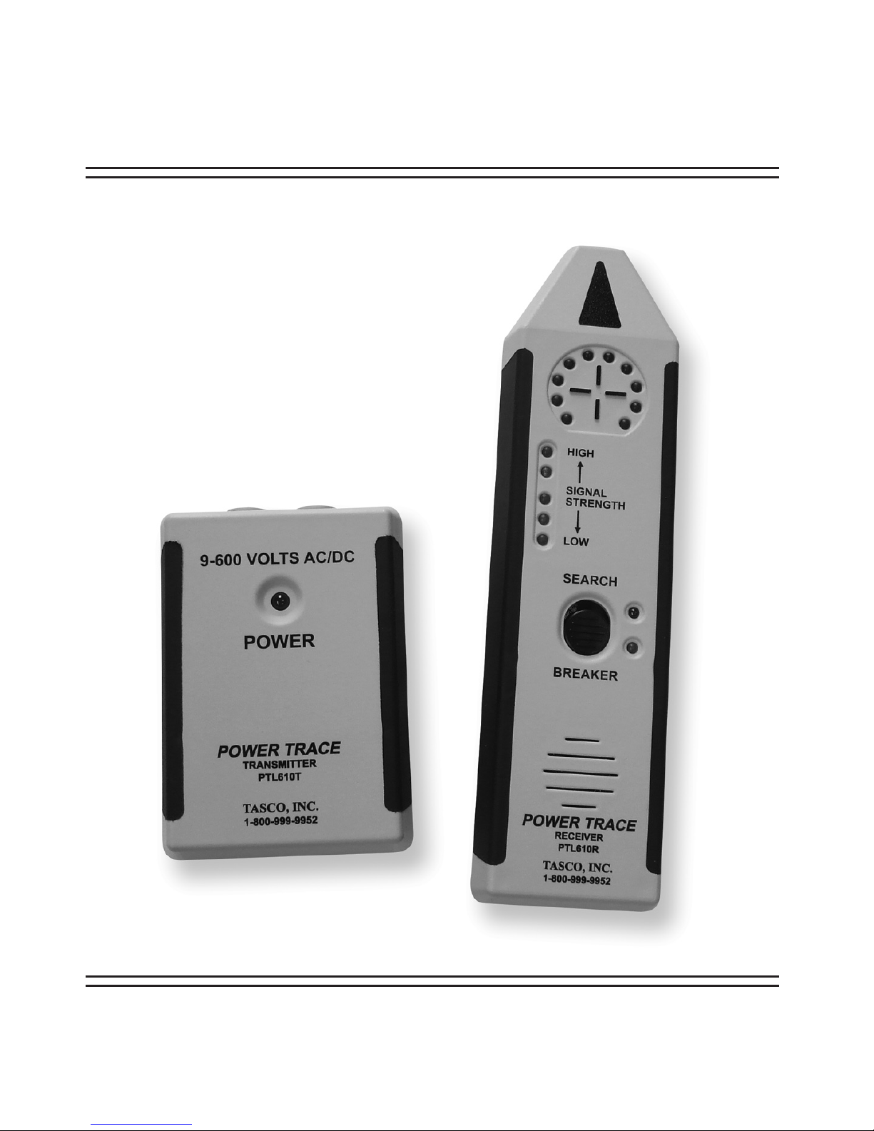
HOW YOUR POWER TRACETM OPERATES
The POWER TRACETM is composed of two primary components: the
Receiver and the Transmitter. When the Transmitter is connected to
any electrical line (up to 600 Volts), it draws a very small current that
is used to create a composite signal. The signal is a microprocessor
controlled combination of separate frequencies that create a specialized “signature” which is recognized by the Receiver.
To be received, the signal must have this exact combination of frequencies.
This feature greatly reduces the possibility of interference from electrical “noise” which is often caused by lamps, electrical equipment,
appliances, florescent fixtures, or machinery that is on the same line.
The signal produced by the Transmitter generates a magnetic “signature” around the conductor being traced which matches that of the
signal itself. This “signature’ is present the entire length of the current
path, including through breakers, fuses, switchgear, and transformers.
The Power Trace
TM
Receiver is “tuned” to pick up only that “signature” produced by the Transmitter. Both the Transmitter and Receiver
are microprocessor controlled for maximum ease of use and accuracy.
TOLL FREE CUSTOMER SERVICE 1.800.999.9952
Page 3
4
5
SOME POWER TRACE
TM
USES
Finding Neutral Wires
Tracing Conduit
Tracing Wires in Walls
Finding Breaker Panel
Identifying Circuit Breakers
Tracing Live Wires
TOLL FREE CUSTOMER SERVICE 1.800.999.9952
Read and understand this material before operating
or servicing this equipment. Failure to understand
how to safely operate this instrument can result in an
accident causing serious injury or death.
Electric shock hazard:
Contact with live circuits can result in severe injury
or death.
THIS TESTER IS DESIGNED FOR USE
BY QUALIFIED ELECTRICIANS.
IMPORTANT SAFETY WARNINGS
Page 4

6
7
HOW TO USE YOUR POWER TRACE
TM
The Transmitter: Just plug into a 120 volt AC circuit. Use insulated
clip leads for connection to other circuits. Do not connect to a voltage
higher than 600 volts or the unit will be DAMAGED! The blinking LED
indicates that the circuit is live and the transmitter is working.
The Receiver: Turn the unit on by pushing and holding the “BREAKER” button. The corresponding LED will light to show the unit is
operating. Use the BREAKER setting anytime you can physically
touch the Receiver tip to the wire or breaker. For all other applications
the SEARCH setting is typically used. It is important to note there is
a distance overlap between the BREAKER and SEARCH settings. If
you do not receive a signal on the BREAKER setting simply use the
SEARCH setting instead. If the Receiver is too close to a line in the
SEARCH setting, and it does not automatically adjust gain, then use
the BREAKER setting instead. Select the range desired by pressing
the button for BREAKER setting or pressing and sliding forward for
SEARCH setting. Operate as indicated in the following instructions.
TRACING LIVE CIRCUITS AND LOCATING CIRCUIT
BREAKERS
1) Plug the Transmitter into the receptacle. The LED will flash indicating the unit is sending signal and connected to an energized line.
2) Push the Receiver button. The unit will beep and the green power
LED next to the button will light. If the green LED flashes, remove and
replace the 9 volt battery. The Receiver will also indicate a signal if
within tracing range.
3) Slide the button forward to the SEARCH position and move the
Receiver to within a few inches of the Transmitter. The red LEDs will
flash and the unit will emit a “beeping” sound.
4) Move the Receiver to the vicinity of the circuit breaker panel, then
press and slide the button to the SEARCH position. If a signal is
received, move the Receiver toward the panel producing an increase
in signal strength which is indicated by both the signal strength and
variable signal circle of LEDs. (The Receiver will pick up a signal within
12 to 18 inches of a panel even with the panel cover closed). Check all
panels without releasing the button to find the strongest signal. This is
the panel containing the breaker feeding the Transmitter.
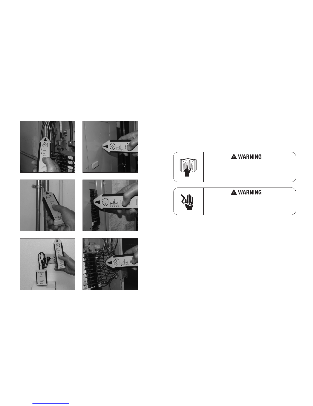
5) Open the panel door, push and hold the BREAKER button, and
sweep the Receiver over all the breakers in the panel as shown. Next,
sweep the Receiver slowly down the rows of breakers until the LEDs
flash. The breaker or fuse providing the highest signal strength and
most variable signal LEDs is the one powering the Transmitter, and
hence, the receptacle or device to which it is connected.
NOTE: The Receiver MUST be held in the position shown to be
aligned with the magnetic field.
TOLL FREE CUSTOMER SERVICE 1.800.999.9952
Page 5

8
9
BUILDING OR EARTH
GROUND (DO NOT USE
CONDUIT ON THE SAME
WIRE RUN)
CLIP
ADAPTER
PLUG
TRANSMITTER
ADAPTER PLUG TO
HOT/TRACE LINE
STANDARD
OUTLET
USING A REMOTE GROUND INCREASES SIGNAL STRENGTH
If there is any doubt as to which is the correct breaker or fuse (due to
unusual breaker design, wiring, or the possibility that two breakers are
feeding the same circuit) remove the panel trim and check the wires.
You can also continue to follow the power line by locating the remote
main breaker in the same fashion. Since the signal is on a single
phase circuit you can even find which leg of the breaker is feeding the
Transmitter.
If there is any doubt as to which breaker is active, remove the
breaker panel trim and test the wires as shown.
Important: Panel trim can distort the signal when locating breakers on
the outside corners of the panel. This can cause stronger signal level
on the adjacent breaker instead of the correct breaker in the corner.
Before labeling any breaker next to the corner breaker, confirm it is the
correct breaker by removing panel trim and repeating the sweep of all
breakers in the panel.
Note: The Receiver MUST be held in the position shown to be aligned
with the magnetic field.
TRACING LIVE WIRES
Any wire carrying the current load from the Transmitter will have the
magnetic signature around it. This means that both the hot and neutral
wires will have the signal.
If hot and neutral are close together as in a cable or conduit they tend
to cancel each other out.
CURRENTS CANCEL MAGNETIC FIELD
CURRENT
CURRENT
TOLL FREE CUSTOMER SERVICE 1.800.999.9952
Page 6

10
11
Although the Power TraceTM is powerful enough to trace these signals
at short distances from cable or conduit, maximum range is obtained
by separating the current paths.
Separating the current path simply means drawing current through the
conductor in one direction by using a remote path.
By using these or similar methods, wiring can be followed up to 20
feet away.
In SEARCH mode, the Receiver will indicate you are within tracing distance by initially flashing all variable signal LEDs. If the signal is lost,
resetting the SEARCH button will adjust the receiver to the appropriate
signal level. The signal strength will increase and the variable signal
LEDs will adjust as you get closer to the signal wire. This creates the
most accurate reading possible based on the Receivers distance from
the signal wire.
NOTE: If the transmitter LED does not flash when using a remote
ground you may have a poor ground connection.
TRACING LOW VOLTAGE CIRCUITS
To trace low voltage circuits (50 volts or less), connect one Transmitter test lead to a known ground, and the other Test lead to the low
voltage conductor.
Operate the Receiver per prior instructions.
TOLL FREE CUSTOMER SERVICE 1.800.999.9952
To Hot
To Cold Water Pipe
or Building Ground
(Solid Ground)
To Hot
To Ground Stake
(Solid Ground)
TRANSMITTER
TRANSMITTER
INSIDE
OUTSIDE
Page 7

12
13
LOCATING DEAD CIRCUITS
A dead circuit caused by a tripped breaker can be located by following the circuit’s neutral line. Connect power from any energized
line and return it through the neutral of the dead circuit. You can
then trace the neutral wire to the panel.
NOTE: You may also find the source or hot wire breaker with this
process, however, the same panel will likely contain both circuits. To
verify this, remove the panel trim and test the neutral wire.
FINDING SHORTS TO GROUND
Typical configuration is shown below. Confirm that the transmitter LED is flashing then follow the wire until the signal disappears,
indicating the location of the short.
TOLL FREE CUSTOMER SERVICE 1.800.999.9952
TRANSMITTER
BATT
TO ANY HOT
OR BATTERY
TO NEUTRAL
USE CLIP LEAD AND AC BLADE ADAPTER
DEAD
CIRCUIT
Page 8

14
15
THIS PAGE INTENTIONALLY LEFT BLANK
TOLL FREE CUSTOMER SERVICE 1.800.999.9952
Page 9

SPECIFICATIONS MODEL PTL610
TRANSMITTER:
Operating Voltage: 9-600 Volts, AC/DC
Power: Line power or 9 volt battery
Current: 8 mA Avg.
Frequency: 15KHz
Operating Temp: 0ºF to 120ºF (-18º - 50ºC)
Size: 3.75” x 2.5’” x 1”
RECEIVER:
Power: 9 Volt Alkaline Battery (included)
Range: up to 20 ft. from circuit
Operating Temperature: 0ºF to 120ºF
(-18º - 50ºC)
Size: 7.5” x 2’” x 1”
WARRANTY:
Tasco, Inc. warrants that The Power TraceTM will be free from defects in workmanship and
materials for a period of two (2) years from the date of purchase.
Tasco, Inc. will, without charge, replace or repair, at its option any warranted product returned
to the Tasco factory service department.
Tasco, Inc. shall not be liable for any consequential damages, including without limitation,
damages resulting from loss of use or damages resulting from use or misuse of this product.
Some states do not allow limitations of incidental or consequential damages, so the above
limitation or exclusion may not apply to you.
This warranty gives you specific rights and you may also have rights which vary from state
to state.
EXCLUSIONS:
This warranty does not apply in the event of misuse or abuse of the product or as a result of
unauthorized repairs or alterations.
NOTICE TO PURCHASER:
All statements, technical information and recommendations contained herein are based on
tests we believe to be reliable, but the accuracy or completeness thereof is not guaranteed,
and the following is made in lieu of all warranties, express or implied: Manufacturer’s only obligation shall be to replace such quantity of the product proved to be defective. Manufacturer
shall not be liable for any injury, loss or damage direct or consequential, arising from the use
or misuse of this product. User shall determine the suitability of the product for his intended
use, and user assumes all risk and liability in connection therewith. No statements or recommendations not contained herein shall have any force or effect unless in an agreement signed
by officers or the manufacturer.
MADE IN THE USA BY:
TASCO, INC.
2895 West Oxford Avenue, #7
Englewood, Colorado 80110
303-762-9952, 1-800-999-9952
www.tasco-usa.com
 Loading...