

Page 1
LIT. #: 9806050605
Instruction Manual • Manuel d’instructions
Manual de instrucciones • Bedienungsanleitung
Manuale di istruzioni • Manual de instruções
Page 2

2
Page 3

3
Index
English ........................................................................................4
Français ....................................................................................12
Español ....................................................................................20
Deutsch ....................................................................................29
Italiano ......................................................................................36
Português .................................................................................44
Page 4
4
I. Basic Binocular Adjustments
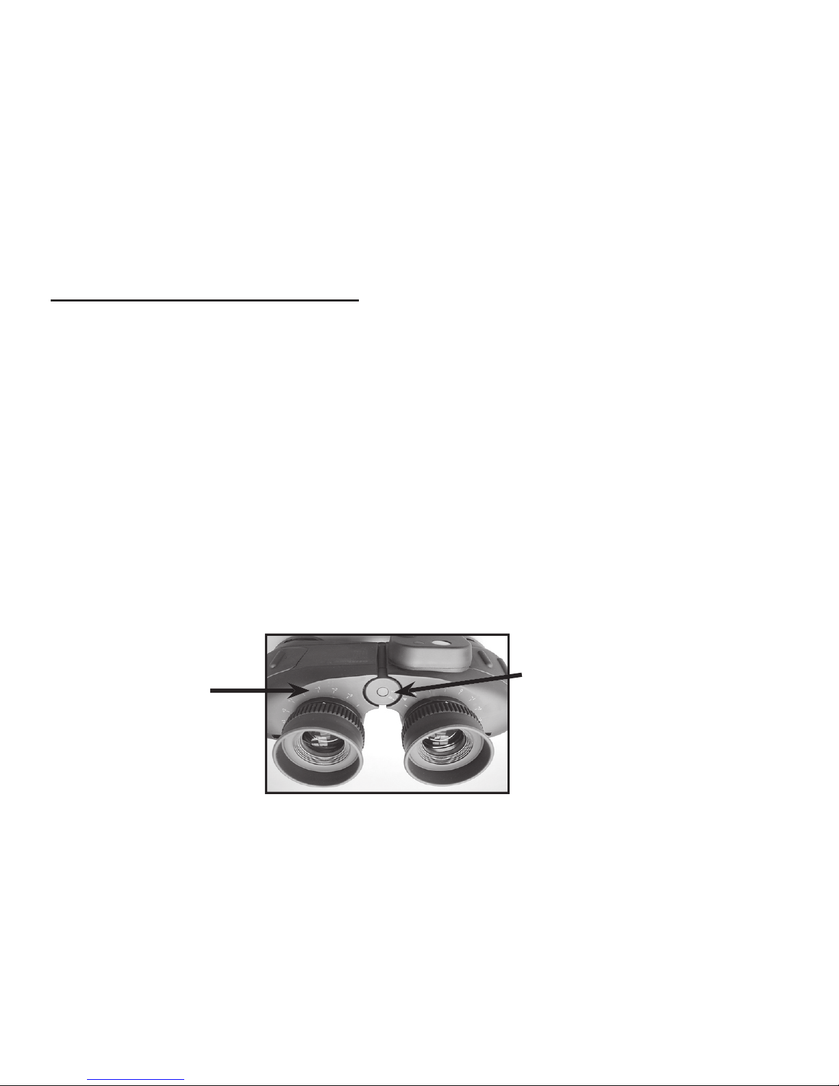
A. IPD Adjustment
Set the interpupillary distance by grasping the body and bending it until you can see a single circular
image. The setting for your eyes will be indicated on the IPD scale. Note this scale setting for quicker
resetting later.
B. Focusing
1. Close your left eye, rotate the right eyepiece until the object appears sharp and clear.
2. Open your left eye, close right eye. Rotate left eyepiece until the object appears sharp and clear.
3. To focus on other objects, repeat Steps 1 and 2.
4. If you share your binocular with another person, note the diopter index mark settings at the base
of the eyepieces fi rst. Then you can simply return the eyepieces to those settings when you next use
the binocular to view an object at the same distance.
C. Rubber Fold-Down Eyecups
These convenient eyecups fold down for use with eyeglasses and fold up for use without eyeglasses.
They provide comfort and promote viewing ease. They will not scratch your glasses.
Diopter
Index
Marks
(both sides)
Page 5

5
II. Using the Reticle and Dial to Determine Distance or Size
Offshore models 36 and 54 have two ranging tools. The eyepiece Reticle Scale and the Calculator
Dial can be used to determine your distance from an object if its size is known, or vice versa. Please
refer to the illustrated example on the next page as you read the following directions.
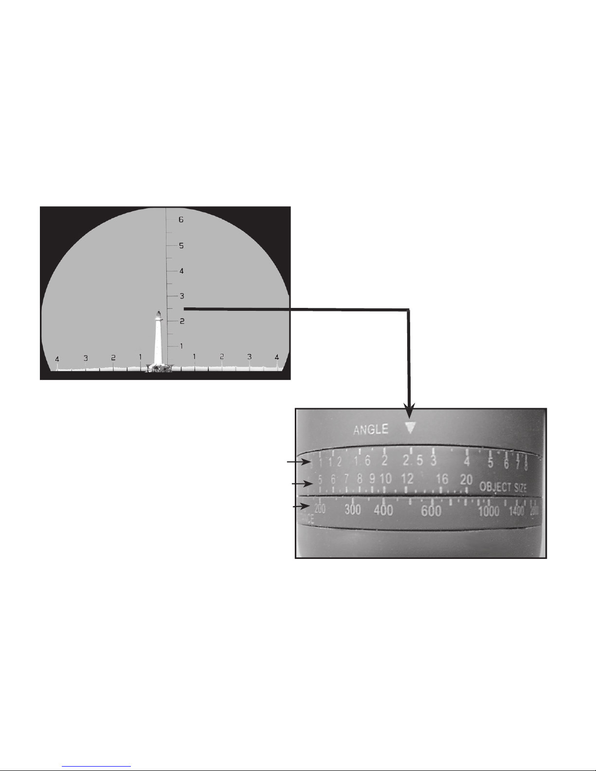
When the object size is known, its distance is determined as follows:
1. Look through your binocular and place the horizontal reticle line at the base of the object
2. Count the number of reticle divisions from the base to the top of the object. (In the example on the
next page, the top of the lighthouse comes to 2.5 on the Reticle Scale)
3. Rotate the Calculator Dial and place this number (2.5) at the Angle Index Mark
4. Assuming you know that the height of the lighthouse is 100 ft., look to the right of the Angle Index
Mark and find the object size on the scale labeled “Object Size”. In this example, use “10”.
NOTE: The object size divisions are from 1 to 20. In dealing with an object that is 100 feet, mentally
add a zero to the 10 indicator on the object size scale.
5. Now read the distance scale directly beneath the object size. It is 400 but remember, because you
added a “0” to the “10” in Step 4, you must add a zero to the 400. Thus, the distance from you to the
lighthouse is 4000 feet.
IMPORTANT: Always remember that the Distance and Object Size scales are in a “ratio” to each other.
When you add “0’s” to one, you must add an equal number of “0’s” to the other as we did in Steps
4 and 5 above.
ENGLISH
Page 6
6
Angle Index
with 2.5 on reticle angle scale. Rotate
calculator dial so “2.5” on angle index
the lighthouse is 4000’.
Page 7

7
When distance to the object is known, its size is determined as follows:
1. Count the reticle divisions occupied by the object
2. Rotate the Calculator Dial, so that the Angle Index Mark points to the number from the reticle scale .
3. Look at the Distance Scale, and fi nd your known distance to the object (for example, 4000 feet,
or 400 on the scale). The number on the Object Size scale that is opposite this distance indicates
the size of the object (for example, 100 feet). As mentioned previously, remember that the distance
and size scales are ratios, be sure to add the same number of zeros to the numbers on both scales
(10:400 / 100:4,000 / 1,000:40,000, etc)
III. Using the Compass
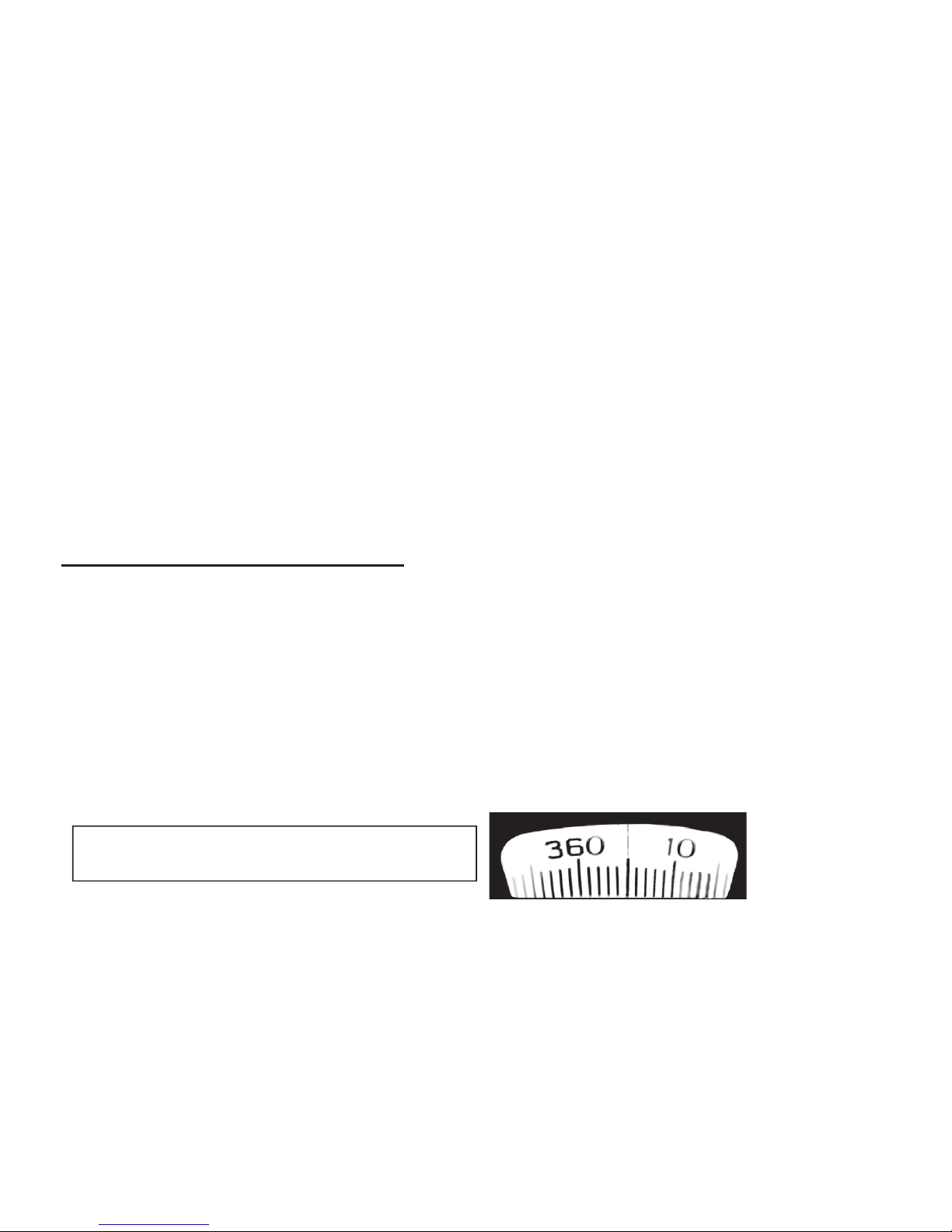
Offshore models 36 and 541 feature a built-in compass with illumination. The compass scale is
refl exed into the eyepiece and can be seen while looking through the binocular. Each scale division
equals 1° of azimuth.
To use the compass, hold the binocular in viewing position and focus on the object. While holding
steady on the object, note the compass reading that appears beneath the fi xed central index line.
The reading will indicate the magnetic direction to the object.
For use at night, locate and focus on an object in the normal manner and when ready to determine
azimuth, press the illuminator switch. The compass scale will be illuminated in red light for easy
viewing, without affecting your night vision.
Compass Scale as seen through right eyepiece
(“0” beneath index line indicates heading is due north)
Page 8

8
Detailed Operational Example:
Navigation with The Compass and Rangefinding Scales
The following examples use nautical situations to explain the use of the compass and Rangefinding scale features.
However, the same principles apply to navigation on land. Please refer to the illustrated figures on the next page
as you read the section below:
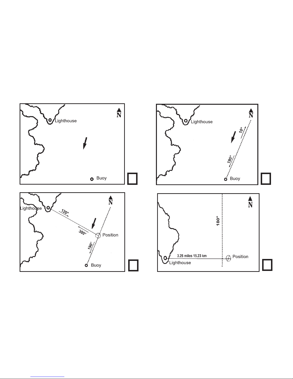
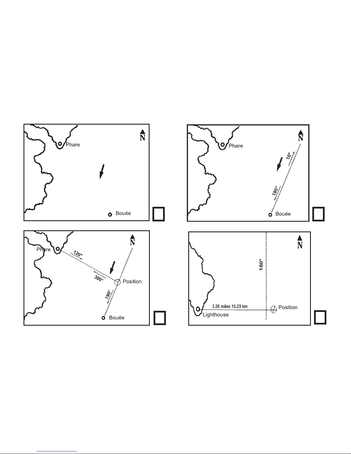
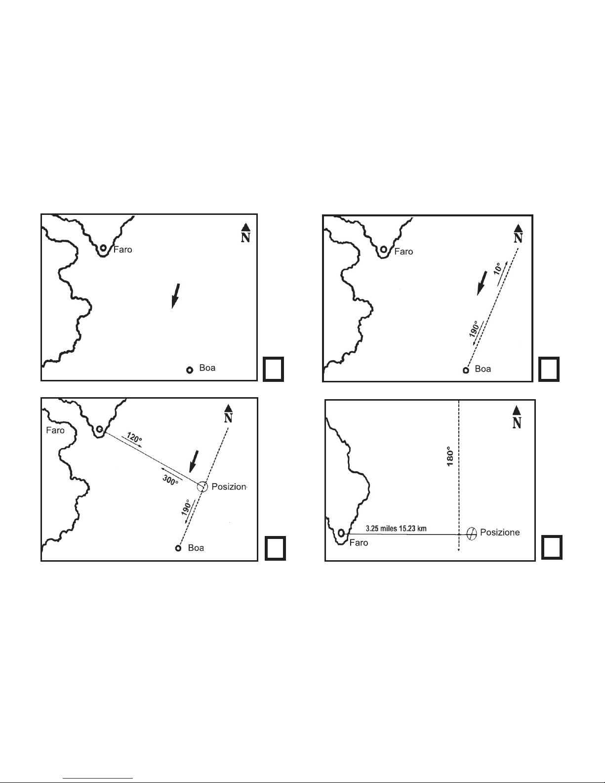
Used by itself, a compass will only indicate direction to or from an object but not relative position. To determine
position, you need a map or chart and a protractor of some type. Figs.1 and 2 illustrate this point. In Fig.1, the arrow
shows your general direction of travel but not your course or position. Fig.2 shows that you have taken a compass
reading from your boat to the buoy and that it is on a bearing of 190°. You now know your course is 190°, but you
still do not know your position.
To determine position, you should now lay in your course line FROM the buoy. Since your direction of travel is
190°, direction FROM the buoy will be 10° (this is known as back azimuth. Back azimuth is compass reading mi
nus 180°). The next step is to take a bearing on a second fixed object. Fig.3 shows that the lighthouse lies
on a bearing of 300° from your position. Laying in the back azimuth of 120° from the lighthouse, your position will
be indicated by the intersection of the two lines.
NOTE: the illustration does not take into account errors in compass readings due to the earth’s magnetic field or
errors induced by the effect of nearby metal objects.
The amount of correction required for errors due to the earth’s magnetic field (know as variation) will be indicated
on your charts. Local disturbances from metal objects, such as engines, fittings, etc. (known as deviation) should
be determined from accurately known fixed positions.
Fig.4 illustrates the use of the rangefinding reticle. You are on a known course of 180° and you know that when you
are abeam of the lighthouse you should be 2 ½ miles from it. The lighthouse is known to be 86’ high, and a range
reading shows that it occupies one division. Using the rangefinding calculations, you determine that you are 3.25
miles east of the lighthouse. You now know that you are east of your intended course by ¾ of a mile.
Page 9
9
1 2
3
4
Page 10

10
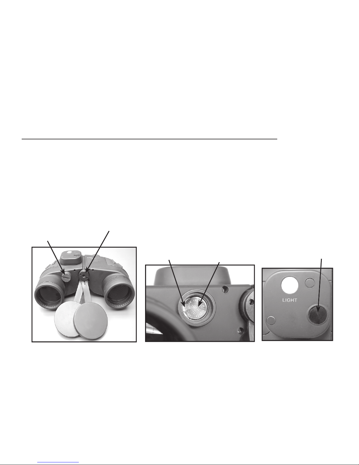
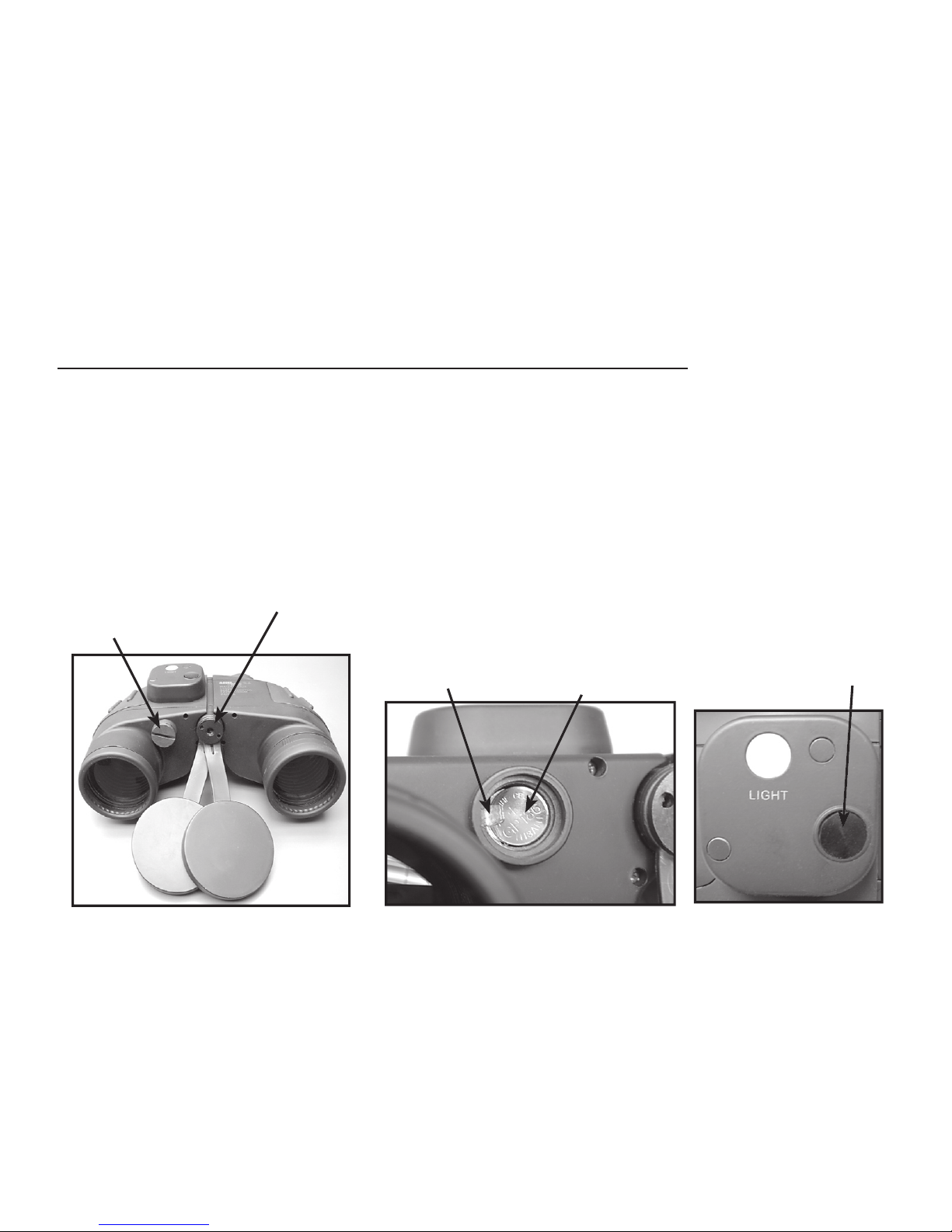
IV. Replacing the Compass Illuminator Batteries (OS 36/54)
Batteries are included and pre-installed in your Offshore binocular. When it becomes necessary to
replace them, unscrew the battery cover with a coin or screwdriver and replace the batteries with the
same type, a pair of alkaline #186 / LR43 , or silver oxide #389 / SR54 batteries. Be sure to install
the batteries in the same direction as the originals, with the fl at positive (+) side facing up towards
the cover on both batteries, and also check that the metal clip is over the positive (+) end of the top
battery as shown. Screw the battery cover back on tightly and press the compass illuminator switch
to test the light-a red glow should be visible around the compass (you may need to cover the right
objective lens if you are outside in bright light).
Battery Cover
Tripod Adapter Socket
Metal Clip
Positive (+)
Facing Up
Compass
Illuminator
Switch
Page 11
11
V. Tripod Mounting
A threaded socket for tripod attachment is located at the base of the binocular hinge (see photo on
previous page). Insert a binocular tripod adapter (Bushnell #161001CM or similar), and attach your
tripod screw to the base of the adapter.
VI. How to Care for Your Binocular
1.Keep the lens covers (that come with your binocular) on the lenses when the binocular is not in use.
2. When wiping the lenses, use the lens cloth that comes with the binocular, or a soft, lintless cloth.
3. To remove any remaining dirt or smudges, add one or two drops of alcohol to the cloth and wipe clean.
4. Store your binocular in a moisture-free area.
5. Should your binocular be exposed to salt water or salt laden humidity, it should be thoroughly
rinsed in fresh water.
IMPORTANT: Never attempt to clean your binocular internally or take it apart. This will
violate your warranty and compromise the waterproof/fogproof integrity of the product.
CAUTION ! Viewing the sun can cause permanent eye damage. Never look directly at
the sun with your binocular.
Page 12

12
I. Réglages de base des jumelles
A. Réglage de la distance interpupillaire (IPD)
Réglez la distance interpupillaire en tenant le corps et en le courbant pour faire apparaître une image
circulaire unique. Le réglage pour vos yeux sera indiqué sur l’échelle IPD. Prenez note de ce réglage
pour pouvoir effectuer rapidement une remise à zéro par la suite.
B. Mise au point
1. Fermez l’oeil gauche, tournez l’oculaire droit jusqu’à ce que l’objet soit net (fi gure 2).
2. Ouvrez l’oeil gauche, fermez l’oeil droit. Tournez l’oculaire gauche jusqu’à ce que l’objet soit net.
3. Pour une mise au point sur d’autres objets, répétez les étapes 1 et 2.
4. Si vous partagez vos jumelles avec quelqu’un d’autre, notez d’abord les réglages de l’échelle dioptrique à la base des oculaires. Ensuite, vous pourrez simplement utiliser ces réglages sur les oculaires la prochaine fois que vous utiliserez les jumelles pour observer un objet à la même distance.
C. Œilletons en caoutchouc rabattables
Ces oeilletons commodes se rabattent vers le bas s’ils sont utilisés avec des lunettes et se relèvent
si utilisés sans lunettes. Ils vous procurent confort et commodité d’observation. Ils ne rayent pas vos
lunettes.
charnière)
Repères
d’index dioptrique (des
deux côtés)
Page 13

13
II. Utilisation du réticule et du cadran pour déterminer la distance ou la taille
Les modèles « Offshore » 36 et 54 disposent de deux outils télémétriques. L’échelle du réticule de
l’oculaire et le cadran du calculateur peuvent être utilisés pour déterminer la distance qui vous sé
pare d’un objet si sa taille est connue ou vice versa. Veuillez vous reporter à l’exemple illustré à la
page suivante lorsque vous lirez ces instructions.
Lorsque la taille de l’objet est connue, sa distance est déterminée comme suit :
1. Regardez dans vos jumelles et placez la ligne de réticule à la base de l’objet.
2. Comptez le nombre de divisions du réticule entre la base et le haut de l’objet. (Dans l’exemple de
la page suivante, le sommet du phare arrive au repère 2,5 sur l’échelle de réticule.)
3. Tournez le cadran du calculateur et placez ce chiffre (2,5) au niveau du repère d’index d’angle.
4. Si vous savez que la hauteur du phare est de 100 pi (30,5 m), regardez à droite du repère pour
trouver la taille connue de l’objet sur l’échelle dite « de taille d’objet ». Dans cet exemple, utilisez « 10 ».
REMARQUE : Les divisions de taille d’objet varient de 1 à 10. Pour un objet de 100 pieds (30,5
mètres), ajoutez mentalement un zéro à l’indicateur 10 sur l’échelle de taille d’objet.
5. Lisez alors l’échelle de distance située directement au-dessous de l’échelle de taille d’objet. Elle
indique 400, mais n’oubliez pas que, puisque vous avez ajouté un « 0 » à la valeur « 10 » à l’étape
4, vous devez ajouter un zéro à la valeur 400. Donc, la distance entre vous et le phare est de 4000
pieds (1219 mètres).
IMPORTANT : N’oubliez jamais qu’il existe un rapport entre les repères de distance et de taille d’objet.
Si vous ajoutez des « 0 » à l’un, vous devez ajouter un nombre égal de « 0 » à l’autre, ainsi que nous
l’avons fait aux étapes 4 et 5 ci-dessus.
FRANÇAIS
Page 14

14
du repère 2,5 sur l’échelle d’angle de réticule.
Tournez le cadran du calculateur de manière
que la valeur « 2,5 » sur l’index d’angle soit en
face du repère. Si l’on sait que le phare mesure
vers le phare est de 4000 pi (1219 m).
Page 15

15
Lorsque la distance de l’objet est connue, sa taille est déterminée comme suit :
1. Comptez les divisions de réticule occupées par l’objet.
2. Tournez le cadran du calculateur de manière que le repère de l’index d’angle pointe vers le chiffre
de l’échelle de réticule.
3. Regardez l’échelle de distance pour trouver la distance connue entre vous et l’objet (par exemple, 4000 pieds (1219 m), ou « 400 » sur l’échelle). Le chiffre de l’échelle de taille d’objet se
trouvant en face de cette distance indique la taille de l’objet (par exemple, 100 pieds (30,5 mètres)).
Comme nous l’avons dit précédemment, n’oubliez pas le rapport entre les échelles de distance
et de taille. Veillez à ajouter le même nombre de zéros aux chiffres fi gurant sur les deux échelles
(10:400 / 100: 4 000 / 1 000: 40 000, etc.
III. Utilisation du navigateur
Les modèles « Offshore » 36 et 541 comportent un navigateur intégré avec illumination. L’échelle
du navigateur se réfl échit dans l’oculaire et peut être vue lorsque l’on regarde dans les jumelles.
Chaque partie de l’échelle équivaut à 1º d’azimut.
Pour utiliser le navigateur, tenez les jumelles en position d’observation et visez l’objet. Tout en restant concentré sur l’objet, prenez note du relevé du navigateur qui apparaît en dessous de la ligne
d’index centrale fi xe. Le relevé indique la direction magnétique vers l’objet.
De nuit, repérez et visez un objet de la manière normale, puis lorsque vous êtes prêt à déterminer
l’azimut, appuyez sur le bouton de l’illuminateur. L’échelle du navigateur s’illuminera en rouge pour
faciliter l’observation sans affecter votre vision nocturne.
(« 0 » sous la ligne d’index indique une direction nord)
Page 16

16
Exemple de fonctionnement détaillé :
Navigation avec le navigateur et les échelles télémétriques
Les exemples suivants reposent sur des conditions d’ordre nautique pour expliquer l’utilisation du navigateur
et de l’échelle télémétrique. Toutefois, les mêmes principes s’appliquent à la navigation terrestre. Veuillez vous
reporter aux figures illustrées à la page suivante lorsque vous lirez la section ci-après :
Utilisé seul, un navigateur n’indique que la direction aller ou retour vers un objet, mais pas sa position relative.
Pour déterminer celle-ci, il vous faut une carte ou un diagramme et un rapporteur. Les figures 1 et 2 illustrent ce
point. Dans la figure 1, la flèche indique votre sens de déplacement général, mais pas votre cap ni votre position.
La figure 2 indique que vous avez effectué un relevé sur le navigateur entre votre embarcation et la bouée et que
le relèvement est de 190º. Vous savez désormais que votre cap est de 190º, mais vous ne connaissez toujours pas
votre position.
Pour déterminer cette position, vous devez maintenant fixer votre cap PAR RAPPORT À la bouée. Étant donné
que votre sens de déplacement est de 190º, la direction PAR RAPPORT À la bouée sera de 10º (cela s’appelle
l’azimut inverse. L’azimut inverse est le relevé du navigateur moins 180º). L’étape suivante consiste à prendre un
relèvement sur un second objet fixe. La figure 3 montre un relèvement du phare de 300º par rapport à votre position.
Utilisant l’azimut inverse de 120º à partir du phare, votre position sera indiquée par l’intersection des deux lignes.
REMARQUE : l’illustration ne tient pas compte des erreurs de lecture du navigateur dues au champ magnétique
de la terre ou des erreurs occasionnées par la présence d’objets métalliques à proximité.
Le degré nécessaire de correction des erreurs dues au champ magnétique de la terre (dites variations) sera
indiqué sur vos diagrammes. Les perturbations locales causées par des objets métalliques tels que moteurs, rac
cords, etc. (dites déviations) doivent être déterminées à partir de positions fixes bien connues.
La figure 4 illustre l’utilisation du réticule télémétrique. Vous êtes sur un cap connu de 180º et vous savez que
lorsque vous êtes par le travers du phare, vous devriez en être à 4 km (2,5 mi). On sait que le phare mesure 26 m
(86 pi) de haut, et un relevé télémétrique indique qu’il occupe une division. À l’aide des calculs télémétriques, vous
déterminez que vous vous trouvez à 5,2 km (3,25 mi) du phare. Vous savez désormais que vous êtes à 1,2 km à
l’est du cap prévu
Page 17
17
1 2
3
4
Page 18

18
IV. Remplacement des piles de l’illuminateur du navigateur
Les piles sont incluses et pré-installées dans vos jumelles « Offshore ». Lorsqu’il est nécessaire de les
remplacer, dévissez le couvercle du compartiment piles avec une pièce de monnaie ou un tournevis et
remplacez les piles par deux piles de même type, alcalines nº 186 / LR43 ou à l’oxyde d’argent nº389 /
SR54. Veillez à installer les piles dans le même sens que celles d’origine, le côté positif plat (+) dirigé
vers le haut, vers le couvercle couvrant les deux piles, et vérifi ez aussi que le clip métallique se trouve sur
l’extrémité positive (+) de la pile du dessus, comme illustré. Revissez le couvercle du compartiment piles
pour le remettre fermement en place et appuyez sur le bouton de l’illuminateur du navigateur pour tester
la luminosité ; une lueur rouge doit être visible autour du navigateur (il se peut que vous soyez obligé
de recouvrir l’objectif si vous vous trouvez dehors exposé à une lumière vive).
Couvercle du
compartiment piles
Adaptateur de trépied
Clip
métallique
Positif (+)
Vers le haut
Bouton de
l’illuminateur
du navigateur
Page 19

19
V. Montage du trépied
Le trépied se fixe à la base de la charnière au moyen d’une douille filetée (voir la photo
à la page précédente). Insérez un adaptateur de trépied (Bushnell nº 161001CM ou équivalent),
et fixez la vis de votre trépied à la base de l’adaptateur.
VI. Entretien de vos jumelles
1. Gardez les capuchons de lentilles (livrés avec vos jumelles) sur les lentilles lorsque les jumelles ne sont pas en usage.
2. Pour nettoyer les lentilles, utilisez le chiffon fourni avec les jumelles, ou bien un chiffon doux,
non pelucheux.
3. Pour enlever la poussière ou les traces, ajoutez une ou deux gouttes d’alcool sur le chiffon et
essuyez.
4. Rangez les jumelles à l’abri de l’humidité.
5. Si vos jumelles sont exposées à l’eau de mer ou à l’humidité saline, elles doivent être bien
rincées à l’eau claire.
IMPORTANT : N’essayez jamais de nettoyer l’intérieur de vos jumelles, ni de les démonter. Cela constituerait une violation de la garantie et compromettrait les caractéristiques
étanches et antibuée du produit.
ATTENTION ! L’observation du soleil peut causer des lésions oculaires permanentes. Ne
regardez jamais le soleil avec vos jumelles.
Page 20

20
I. Ajustes básicos del binocular
A. Ajuste de la DIP (IPD, en inglés)
Fije la distancia interpupilar agarrando el cuerpo del binocular y doblándolo hasta que vea una imagen circular única. La posición para sus ojos se indicará en la escala DIP. Anote esta posición en la
escala para poder reposicionarlo con mayor rapidez después.
B. Enfoque
1. Cierre el ojo izquierdo, gire el ocular derecho hasta que el objeto aparezca nítido y claro (Fig. 2)
2. Abra el ojo izquierdo, cierre el ojo derecho. Gire el ocular izquierdo hasta que el objeto aparezca nítido y claro.
3. Para enfocar otros objetos, repita los pasos 1 y 2.
4. Si va a compartir sus binoculares con otra persona, anote primero las posiciones de la escala de ajuste
dióptrico de la base de los oculares. De esta forma sólo tiene que volver a poner los oculares en esas posiciones cuando vuelva a usar los binoculares para ver un objeto que esté situado a la misma distancia.
C. Ojeras de caucho plegables
Estas prácticas ojeras pueden plegarse para usarse con gafas o desplegarse si no se usan gafas.
Ofrecen confort y facilitan la visión. No producen arañazos en las gafas.
tapa de bisagra)
Marcas
de índice
dióptrico
(ambos
lados)
Page 21

21
II. Cómo se usan la retícula y el cuadrante p ara determinar la distancia o
el tamaño
Los modelos Offshore 36 y 54 disponen de dos dispositivos de medición. Se puede usar la escala
reticular del ocular y el cuadrante calculador para determinar la distancia desde un objeto si se conoce su tamaño, o viceversa. Consulte el ejemplo ilustrado de la siguiente página a medida que lee
las siguientes instrucciones.
Cuando se conoce el tamaño del objeto, su distancia se determina como sigue:
1. Look through your binocular and place the horizontal reticle line at the base of the object
1. Mire por el binocular y coloque la línea reticular horizontal en la base del objeto.
2. Cuente el número de divisiones de la retícula desde la base hasta la parte superior del objeto. (En
el ejemplo de la página siguiente, la parte superior del faro alcanza 2.5 en la escala reticular)
3. Gire el cuadrante calculador y ponga este número (2.5) en la marca del índice angular.
4. Asumiendo que sabe que el faro mide 100 pies de altura, mire a la derecha de la marca del índice angular y busque el tamaño del objeto conocido en la escala de “Tamaño del objeto”. En este
ejemplo, use “10”.
NOTA: Las divisiones del tamaño del objeto van de 1 a 10. En el caso de un objeto que de 100 pies,
añada mentalmente un cero al indicador 10 de la escala de tamaño del objeto.
5. Ahora lea la escala de distancia directamente debajo del tamaño del objeto. Es 400, pero recuerde que como añadió un “0” al “10” en el paso 4, tiene que añadir un cero al 400. Por lo tanto, la
distancia desde donde está usted hasta el faro es de 4000 pies.
IMPORTANTE: Recuerde siempre las marcas de Distancia y Tamaño del objeto como una “relación”
entre sí. Cuando añada un “0” a una, tiene que añadir el mismo número de “ceros” a la otra como
hicimos en los Pasos 4 y 5 anteriormente.
ESPAÑOL
Page 22

22
a nivel con 2.5 en la escala angular de la
frente a la marca. Si se sabe que el faro
de 4000’.
Page 23

23
Cuando se conoce la distancia hasta el objeto, su tamaño se determina como sigue:
1. Cuente las divisiones de la retícula ocupadas por el objeto.
2. Gire el Cuadrante calculador, de forma que la marca de índice angular apunte al número de la
escala reticular.
3. Mire la Escala de distancia y busque la distancia conocida hasta el objeto (por ejemplo, 4000
pies, o “400” en la escala). El número de la escala del Tamaño del objeto que esté frente a esta
distancia indicará el tamaño del objeto (por ejemplo, 100 pies). Como mencionamos anteriormente,
recuerde que las escalas de distancia y tamaño están relacionadas y hay que añadir el mismo
número de ceros a los números de ambas escalas (10:400 / 100:4,000 / 1,000:40,000 etc)
III. Cómo se usa la compás
Los modelo Offshore 36 y 541 tienen un compás integrado con iluminación. La escala del compás
se refl eja en el ocular y se puede ver mientras se mira por el binocular. Cada división de la escala
es igual a 1° de azimut.
Para usar el compás, sujete el binocular en posición de mirar y enfoque el objeto. Mientras lo mantiene con fi rmeza sobre el objeto, observe la lectura del compás que aparece debajo de la línea de
referencia central fi ja. La lectura indicará la dirección magnética hasta el objeto.
Para usarlo durante la noche, localice y enfoque un objeto siguiendo el método normal y cuando
esté listo para determinar el azimut, pulse el botón del iluminador. La escala del compás se iluminará con una luz roja para facilitar la visión sin afectar su visión nocturna.
lar derecho (“0”debajo de la línea de referencia indica que el
rumbo es norte)”
Page 24

24
Ejemplo de funcionamiento detallado:
Navegación con las escalas del compás y el telémetro
Los siguientes ejemplos utilizan situaciones náuticas para explicar el uso de las funciones de las escalas del
compás y el telémetro. Sin embargo, en tierra se aplican los mismos principios de la navegación. Consulte las
figuras ilustradas de la página siguiente a medida que vaya leyendo la sección que viene a continuación:
Utilizado por sí misma, un compás sólo indicará la dirección hasta un objeto, o desde el mismo, pero no su
posición relativa. Para determinar la posición, se necesita un mapa o una carta de navegación y algún tipo de
transportador. Las figuras 1 y 2 ilustran este punto. En la figura.1, la flecha muestra la dirección de desplazamiento
general pero no el rumbo ni la posición. La figura 2 muestra que se ha tomado una lectura del compás desde el
barco a la boya y que está siguiendo un rumbo de 190°. Aunque sepa que está siguiendo un rumbo de 190°, sigue
sin saber su posición.
Para determinar la posición, tiene que marcar su línea de rumbo DESDE la boya. Como quiera que la dirección
de desplazamiento es de 190°, la dirección DESDE la boya será de 10° (que se conoce como azimut inverso. El
azimut inverso es una lectura de compás de menos 180°). El siguiente paso consiste en tomar el rumbo sobre un
segundo objeto fijo. La figura 3 muestra que el faro se encuentra en un rumbo de 300° desde su posición. En base
al azimut inverso de 120° desde el faro, su posición vendrá indicada por la intersección de las dos líneas.
NOTA: la ilustración no tiene en cuenta los errores en las lecturas del compás a causa del campo magnético de la
Tierra ni los errores inducidos por el efecto de objetos metálicos cercanos.
La cantidad de corrección que se requiere a causa de los errores debidos al campo magnético de la Tierra (que se
conoce como variación) vendrá indicado en las cartas marinas. Las alteraciones locales a causa objetos metálicos,
como motores, acoples, etc. (que se conoce como desviación) deberá determinarse a partir de posiciones fijas que
se conozcan con precisión.
La figura 4 ilustra el uso de la retícula del telémetro. Usted se encuentra en un rumbo conocido de 180° y sabe
que cuando esté en ángulo recto con la quilla con respecto al faro deberá encontrarse a una distancia de 2 ½ del
mismo. Se sabe que el faro mide 86’ de altura, y la lectura del telémetro muestra que ocupa una división. Usando
los cálculos de telemetría, usted determina que está a 3,25 millas del faro. Ahora sabe que se encuentra a ¾ de
milla al Este de su rumbo previsto.
Page 25

25
1 2
3
4
Faro
Faro
Page 26
26
IV. Cómo se sustituyen las pilas del iluminador del Compás
Las pilas están incluidas y vienen preinstaladas en el binocular Offshore. Cuando haya que sustituirlas, desatornille la cubierta de las pilas con una moneda o un destornillador y sustituya las pilas
por otras nuevas del mismo tipo, un par de pilas alcalinas #186 / LR43 o pilas de óxido de plata
#389 / SR54. Asegúrese de instalar las pilas en la misma dirección que las originales, con el lado
positivo (+) plano mirando arriba hacia la cubierta en ambas pilas, y compruebe también que el clip
de metal esté sobre el extremo positivo (+) de la pila superior, como se muestra. Vuelva a atornillar
bien la cubierta de las pilas y pulse el botón del iluminador del compás para probar la luz-deberá
verse un brillo rojo alrededor del compás (puede que tenga que cubrir el objetivo derecho si está
al aire libre con luz brillante).
Cubierta de las pilas
Zócalo adaptador para trípode
Clip de metal
Positivo (+)
Mirando hacia arriba
Botón del
ilumina-
dor del
compás
Page 27
27
V. Montaje del trípode
En la base de la articulación del binocular hay un zócalo de fijación roscado para conectar el
trípode (véase fotografía en la página anterior). Inserte un adaptador de trípode para binocular
(Bushnell #161001CM o similar), y conecte el tornillo del trípode a la base del adaptador.
VI. Cómo cuidar los binoculares
1. Mantenga las cubiertas de las lentes (que vienen con los binoculares) en las lentes cuando no
use los binoculares.
2. Cuando limpie las lentes, use el paño para lentes que viene con los binoculares, o un paño
suave y sin pelusa.
3. Para quitar cualquier suciedad o mancha, eche una o dos gotas de alcohol al paño y limpie
frotando.
4. Guarde los binoculares en un lugar seco.
5. Si sus binoculares quedaran expuestos al agua salada o a humedad que tenga sal, deberán
enjuagarse bien en agua dulce.
IMPORTANTE: No trate nunca de limpiar los binoculares internamente ni de desmontarlos. Así se violaría la garantía y comprometería la integridad de impermeabilidad /
protección contra el empañamiento del producto.
¡PRECAUCIÓN! Mirar al Sol podría causar daños permanentes a los ojos. No mire nunca
directamente al Sol con los binoculares.
Page 28

28
I. Grundlegende Fernglaseinstellungen
A. IPD Einstellung (Pupillenabstand)
Den Pupillenabstand einstellen, indem der Körper erfaßt und soweit gebeugt wird, bis ein einziges rundes
Bild zu sehen ist. Die Einstellung der Augen wird auf der IPD Skala angegeben. Diese Skaleneinstellung
für später rascheres Einstellen notieren.
B. Fokussierung
1. Das linke Auge schließen, das rechte Okular drehen, bis das Objekt scharf und klar erscheint (Abb. 2).
2. Das linke Auge öffnen, das rechte Auge schließen. Das linke Okular drehen, bis das Objekt scharf und
klar erscheint.
3. Zum Fokussieren auf andere Objekte die Schritte 1 und 2 wiederholen.
4. Wenn mehrere Leute das Fernglas benutzen, vorher die Skaleneinstellung der Dioptrienanpassung
unten an den Okularen notieren. Dann können die Okulare einfach auf diese Einstellungen zurückgeführt
werden, wenn mit dem Fernrohr später ein Objekt in der gleichen Entfernung betrachtet werden soll.
C. Herunterklappbare Augenmuscheln aus Gummi
Diese angenehmen Augenmuscheln können von Brillenträgern nach unten geklappt werden und nach
oben bei Benutzung ohne Brille. Dies sorgt für Komfort und fördert das leichte Betrachten. Sie verkratzen
keine Brillen.
Dioptrienindexmarkierungen
(beide
Seiten)
Page 29

29
II. Benutzung von Fadenkreuz und Wählscheibe zur Bestimmung von
Entfernung oder Größe
Die Offshore Modelle 36 und 54 haben zwei Werkzeuge für die Entfernungsmessung. Die Fadenkreuzskala des Okulars und die Rechenwählscheibe können benutzt werden, um die Entfernung
von einem Objekt zu bestimmen, wenn sein Größe bekannt ist, und umgekehrt. Siehe beim Lesen
der nachstehenden Anwendungen das illustrierte Beispiel auf der nächsten Seite.
Wenn die Objektgröße bekannt ist, wird seine Entfernung wie folgt bestimmt:
1. Durch das Fernglas schauen und die horizontale Fadenkreuzlinie auf die Basis des Objekts
setzen.
2. Die Anzahl Unterteilungen des Fadenkreuzes von unten nach oben am Objekt zählen. (Im
Beispiel auf der nächsten Seite kommt die Spitze des Leuchtturms auf 2,5 auf der Fadenkreuzskala).
3. Die Rechenwählscheibe drehen, und diese Zahl (2,5) auf die Winkelindexmarkierung setzen.
4. Angenommen, es ist bekannt, daß der Leuchtturm 30 m hoch ist, rechts neben der Winkelindexmarkierung schauen und die bekannte Objektgröße auf der Skala mit „Objektgröße“ herausfinden.
In diesem Beispiel „10“ benutzen.
HINWEIS: Die Unterteilungen für die Objektgrößen gehen von 1 bis 10. Bei einem Objekt mit 30 m
im Kopf eine 0 zum Anzeiger der 10 auf der Objektgrößenskala zufügen.
5. Jetzt die Entfernungsskala direkt unter der Objektgröße ablesen. Dort steht 400, aber daran
denken, da in Schritt 4 eine “0” zu den “10” zugefügt wurde, muß eine Null zu den 400 zugefügt
werden. Somit beträgt die Entfernung bis zum Leuchtturm 4.000 Fuß (1.220 m).
WICHTIG: Immer daran denken, daß die Entfernungs- und Objektgrößenmarkierungen in einem
“Verhältnis“ zueinander stehen. Wenn Nullen zu einem hinzugefügt werden, muß die gleiche Anzahl Nullen zum anderen hinzugefügt werden, wie in den obigen Schritten 4 und 5 geschehen.
DEUTSCH
Page 30

30
Winkelindex
Winkelindexskala des Fadenkreuzes
“2,5” auf dem Winkelindex gegenüber der
der Leuchtturm 30 m hoch ist, beträgt die
Page 31
31
Wenn die Entfernung zum Objekt bekannt ist, wird seine Größe wie folgt bestimmt:
1. Die vom Objekt belegten Unterteilungen des Fadenkreuzes zählen.
2. Die Rechenwählscheibe drehen, damit die Winkelindexmarkierung auf die Zahl der Fadenkreuzskala zeigt.
3. Auf die Entfernungsskala schauen und die bekannte Entfernung bis zum Objekt herausfi nden
(zum Beispiel 1.220 m oder “400” auf der Skala). Die Zahl auf der Objektgrößenskala, die gegenüber
dieser Entfernung steht, gibt die Größe des Objekts an (zum Beispiel 30 m). Wie vorher erwähnt, daran denken, daß die Entfernungs- und Größenskalen im Verhältnis stehen, die gleiche Anzahl Nullen
zu den Zahlen auf beiden Skalen hinzufügen (10:400 / 100:4,000 / 1,000:40,000, usw.).
III. Benutzung des Kompasses
Die Offshore Modelle 36 und 541 haben einen eingebauten Kompaß mit Beleuchtung. Die Kompaßskala refl ektiert in das Okular und ist sichtbar, während durch das Fernglas geschaut wird.
Jede Skalenunterteilung ist gleich 1° Azimut.
Für die Benutzung des Kompasses das Fernglas in Sichtposition halten und auf das Objekt fokussieren. Bei gleichbleibendem Zuhalten auf das Objekt den Kompaßwert notieren, der unter der
feststehenden Mittelindexlinie erscheint. Der Wert gibt die magnetische Richtung zum Objekt an.
Für die Benutzung in der Nach, auf normalem Wege ein Objekt lokalisieren und darauf fokussieren, und zur Bestimmung des Azimuts den Illuminatorschalter drücken. Die Kompaßskala wird
zum leichten Ablesen rot beleuchtet, ohne die Nachtsicht zu beeinträchtigen.
“Kompaßskala, wie sie durch das rechte Okular gesehen wird,
(“0” unter der Indexlinie gibt die Richtung Nord an).
Page 32

32
Ausführliches Betriebsbeispiel:
Navigation mit dem Kompaß und Entfernungsmessungsskalen
In den nachstehenden Beispielen werden nautische Situationen dazu eingesetzt, die Benutzung des Kompasses
und der Entfernungsmessungsskalen zu erklären. Die gleichen Prinzipien gelten jedoch auch zur Navigation
an Land. Beim Lesen des nachfolgenden Abschnitts bitte die illustrierten Abbildungen auf der nächsten Seite
betrachten:
Wenn der Kompaß allein benutzt wird, gibt er nur die Richtung zu oder von einem Objekt an, aber keine relative
Position. Zur Bestimmung der Position ist eine Land- oder Seekarte erforderlich und eine Art Winkelmesser. Dieser
Punkt wird in den Abb. 1 und 2 gezeigt. Der Pfeil in Abb. 1 zeigt die allgemeine Reiserichtung, aber weder den
Kurs, noch die Position. Abb. 2 zeigt, daß ein Kompaßwert vom Schiff bis zur Boje genommen wurde, und daß es
auf einer Ortung von 190° liegt. Der Kurs von 190° ist bekannt, aber die Position noch nicht.
Für die Positionsbestimmung müßte man in der Kurslinie AB der Boje liegen. Da die Reiserichtung 190° lautet,
ist die Richtung AB der Boje 10° (dies ist als Rück-Azimut bekannt. Der Rück-Azimut ist der Kompaßwert minus
180°). Der nächste Schritt besteht darin, eine Ortung an einem zweiten feststehenden Objekt zu nehmen. Die Abb.
3 zeigt, daß der Leuchtturm auf einer Ortung von 300° ab der eigenen Position liegt. Im Rück-Azimut von 120° vom
Leuchtturm liegend, wird die eigene Position durch den Schnittpunkt der beiden Linien angegeben.
HINWEIS: Die Illustration berücksichtigt keine Fehler der Kompaßwerte durch das Magnetfeld der Erde oder
Fehler durch die Wirkung benachbarter Metallobjekte.
Der erforderliche Korrekturumfang wegen Fehlern aufgrund des Magnetfelds der Erde (als Variation bekannt)
wird auf den Seekarten angegeben. Örtliche Störungen durch Metallobjekte, wie Maschinen, Armaturen, usw. (als
Abweichung bekannt) sollten ausgehend von genau bekannten festliegenden Positionen bestimmt werden.
Abb. 4 illustriert die Benutzung des Fadenkreuzes für die Entfernungsmessung. Wenn man sich auf einem
bekannten Kurs von 180° befindet und weiß, daß, wenn man querab vom Leuchtturm ist, man sich in 2,5 Meilen
davon entfernt befindet. Es ist bekannt, daß der Leuchtturm 26 m hoch ist, und eine Entfernungsmessung zeigt,
daß er eine Unterteilung belegt. Anhand der Berechnungen der Entfernungsmessungen kann man bestimmen,
daß man sich 3,25 Meilen östlich vom Leuchtturm befindet. Jetzt weiß man, daß man sich um ¾ Meile östlich vom
beabsichtigten Kurs befindet.
Page 33

33
1 2
3
4
Page 34

34
IV. Batterienersatz des Kompaß-Illuminators
Das Offshore Fernglas wird mit vorinstallierten Batterien geliefert. Wenn sie ausgetauscht werden
müssen, den Batteriefachdeckel mit einer Münze oder einem Schraubenzieher losschrauben
und die Batterien mit dem gleichen Typ ersetzen, zwei Alkali #186 / LR43 oder Silberoxid #389 /
SR54 Batterien. Darauf achten, die Batterien in der gleichen Richtung wie die Originale mit der
fl achen positiven (+) Seite beider Batterien nach oben zum Deckel einzusetzen, und auch prüfen,
daß der Metallclip über dem positiven (+) Ende der oberen Batterie wie gezeigt liegt. Den Batteriefachdeckel wieder fest aufschrauben, und den Schalter des Kompaß-Illuminators drücken,
um das Licht zu testen – es sollte ein roter Schein um den Kompaß herum zu sehen sein. (Wenn
man sich dabei im Freien und in hellem Licht befi ndet, kann es sein, daß die rechte Objektivlinse
abgedeckt werden muß.
Batteriefachdeckel
Adapterbuchse
für Stativ
Metallclip
Positiv (+)
Nach oben
Schalter des
Kompaß-Illuminators
Page 35

35
V. Stativmontage
An der Basis des Fernglasgelenks befindet sich eine Gewindebuchse für die Stativbefestigung
(siehe Foto auf der vorherigen Seite). Einen Stativadapter für Fernglas einsetzen (Bushnell Nr.
161001CM oder ähnlich) und die Stativschraube an der Basis des Adapters festschrauben
.
VI. Die Pflege des Fernglases
1. Die (mit dem Fernglas gelieferten) Linsenkappen auf den Linsen lassen, wenn das Fernglas
nicht benutzt wird.
2. Zum Abwischen der Linsen das mitgelieferte Linsentüchlein oder ein weiches flusenfreies
Tuch benutzen.
3. Zum Entfernen von eventuell verbleibendem Schmutz oder Fingerspuren einen oder zwei
Tropfen auf dem Tuch hinzufügen und damit sauberwischen.
4. Das Fernglas an einem trockenen Ort aufbewahren.
5. Sollte das Fernglas Salzwasser oder salziger Feuchtigkeit ausgesetzt werden, sollte es
gründlich in frischem Wasser abgespült werden.
WICHTIG: Nie versuchen, das Fernglas innen zu säubern, oder es zu zerlegen. Dies
verletzt die Garantie und stört die wasserfeste / beschlagfreie Beschaffenheit des
Produkts.
ACHTUNG! Das Betrachten der Sonne kann dauernden Augenschaden verursachen.
Niemals mit dem Fernglas direkt die Sonne betrachten.
Page 36

36
I. Regolazioni di base del binocolo
A. Regolazioni dell’IPD
Per fi ssare la distanza interpupillare basta afferrare il corpo e piegarlo fi no a quando non si vede una
sola immagine circolare. La regolazione per i propri occhi sarà indicata sulla scala IPD. Annotarla per
facilitare eventuali regolazioni future.
B. Messa a fuoco
1. Chiudere l’occhio sinistro. Ruotare l’oculare destro fi no a quando l’oggetto osservato appare vivido
e distinto (Fig. 2).
2. Aprire l’occhio sinistro e poi chiudere quello destro. Ruotare l’oculare sinistro fi no a quando l’oggetto
osservato appare vivido e distinto.
3. Per mettere a fuoco altri oggetti, ripetere le operazioni ai punti 1 e 2.
4. Si raccomanda di prendere nota della propria regolazione diottrica, indicata alla base dell’oculare,
prima di passare il binocolo ad altre persone. La prossima volta che si utilizzerà il binocolo per osservare un oggetto alla stessa distanza basterà regolare gli oculari sullo stesso valore.
C. Bordi degli oculari in gomma rovesciabili
Molto pratici: chi porta gli occhiali può girarli verso il basso e chi non li porta li lascia sollevati. Sono
confortevoli e facilitano l’osservazione. Non graffi ano gli occhiali.
tappo apribile)
Diottrie (su
entrambi i
lati)
Page 37

37
II. Uso del reticolo e del quadrante per definire distanze o dimensioni
I modelli Offshore 36 e 54 sono dotati di due apparati di determinazione delle distanze (ranging) La
scala del reticolo dell’oculare e il quadrante di calcolo possono essere usati per stabilire la distanza
da sé stessi ad un determinato oggetto se se ne conoscono le dimensioni, o vice versa. Fare riferimento all’esempio illustrato nella pagina seguente durante la lettura delle istruzioni:
Se si conoscono le dimensioni dell’oggetto, calcolare la distanza:
1. Guardare nel binocolo e posizionare la linea orizzontale del reticolo alla base dell’oggetto.
2. Contare le zone di incremento del reticolo comprese tra la base e la cima dell’oggetto. (Nell’esempio
riportato nella pagina seguente, la cima del faro è a 2.5 sulla scala del reticolo).
3. Posizionare la freccia dell’angolazione (sul quadrante di calcolo) in corrispondenza di questo
numero (2.5).
4. Si presuma che il faro sia alto 100 piedi (30 metri). Guardare a destra dell’indicatore dell’angolazione
e individuare le dimensioni dell’oggetto sulla scala marcata “Object Size” (Dimensioni oggetto).
Usare “10” per questo esempio.
NOTA: le dimensioni degli oggetti sono ripartite da 1 a 10. Se l’oggetto è 100 piedi (30 metri), aggiungere mentalmente uno zero al 10 sull’indicatore della scala delle dimensioni degli oggetti.
5. Leggere la scala della distanza sotto quella delle dimensioni degli oggetti. La distanza risulta essere 400 piedi (122 metri). Ricordare, però, che dato che si è aggiunto uno “0” al “10” (vedi il punto
4), occorre aggiungere uno zero anche a 400. Quindi la distanza dall’osservatore al faro è 4.000
piedi (1.220 metri).
IMPORTANTE: tenere sempre presente che i parametri Distanza e Dimensioni Oggetto sono in “rapporto” tra di loro. Se si aggiungono degli “0” ad uno dei due, occorre aggiungere lo stesso numero di
“0” anche all’altro, come si è fatto ai punti 4 e 5.
ITALIANO
Page 38

38
Scala dimensioni oggetto
Scala distanza oggetto
Angolazione
Scala angolazione reticolo
de a 2.5 sulla scala di angolazione del reticolo.
fi no a posizionare “2.5” in posizione opposta
al marchio sull’indice di angolazione. Il faro, se
4.000 piedi (1.220 metri) dall’osservatore.
Page 39

39
Se si conosce la distanza da sé stessi all’oggetto, determinarne le dimensioni:
1. Contare le graduazioni del reticolo occupate dall’oggetto.
2. Ruotare il quadrante di calcolo in modo che la freccia indicatrice dell’angolazione punti al numero
della scala del reticolo.
3. Guardare la scala della distanza. Individuare la distanza nota da sé stessi all’oggetto (per esempio 4000 piedi/1220 metri, ovvero “400” sulla scala). Il numero sulla scala Object Size (Dimensioni
Oggetto) in posizione opposta a questa distanza indica le dimensioni dell’oggetto (per esempio 100
piedi, ovvero 30 metri). Si rammenta ancora una volta che le scale delle distanze e delle dimensioni
rappresentano dei rapporti. Quindi, assicurarsi di aggiungere lo stesso numero di zeri ai numeri di
entrambe le scale (10:400 / 100:4.000 / 1.000:40.000, ecc.).
III. Utilizzo della bussola
I modelli Offshore 36 e 541 sono dotati di bussola incorporata con illuminazione. La scala della bussola è rifl essa nell’oculare e può essere osservata mentre si guarda nel binocolo. Ogni graduazione
della scala corrisponde ad 1° azimut.
Per usare la bussola è suffi ciente tenere il binocolo in posizione di osservazione e metterlo a fuoco
sull’oggetto. Mentre lo si tiene fi sso sull’oggetto, osservare la lettura della bussola che appare sotto
la linea dell’indicatore centrale fi sso. La lettura indica la direzione magnetica dell’oggetto.
Per illuminare la bussola di notte: individuare l’oggetto desiderato, metterlo a fuoco e, quando si
è pronti a determinare l’azimut, premere l’interruttore dell’illuminatore. La scala della bussola si illumina di rosso per facilitare la lettura senza ridurre la visione notturna.
“La scala della bussola vista attraverso l’oculare destro (lo
“0” sotto la linea dell’indicatore segnala che si sta puntando
verso il nord)”.
Page 40

40
Esempio pratico dettagliato:
Navigazione con bussola e scale telemetriche
Negli esempi seguenti si spiega l’uso della bussola e delle scale telemetriche in campo nautico Gli stessi principi valgono per la navigazione sulla terraferma. Fare riferimento alle illustrazioni nella pagina
seguente durante la lettura:
Se usata da sola, la bussola indica soltanto la direzione verso/da un oggetto, non la posizione relativa.
Per determinare quest’ultima occorre disporre di una cartina e di un goniometro. Vedere le Figure 1 e 2.
Nella Fig. 1 la freccia indica il senso generale in cui si procede, ma non la rotta o la posizione. Nella Fig.
2 è illustrato il valore letto dalla bussola: 190° dall’imbarcazione alla boa. Ora si sa che la rotta è 190°, ma
non si conosce la propria posizione.
Per determinarla occorre tracciare la linea della propria rotta DALLA boa. Dato che il senso di direzione è
190°, la direzione DALLA boa sarà di 10° (viene chiamato ‘angolo opposto a quello azimutale’. L’angolo opposto a quello azimutale è il valore letto sulla bussola meno 180°). Quindi, trovare la posizione di un secondo oggetto fisso. La Fig.3 mostra che il faro è a 300° dalla propria posizione. Se si traccia l’angolo opposto
a quello azimutale, 120° dal faro, la propria posizione viene indicata dall’intersezione delle due righe.
NOTA: l’illustrazione non tiene conto di eventuali errori di lettura della bussola causati dal campo magnetico terrestre o da eventuali oggetti metallici nelle vicinanze.
La correzione necessaria per gli errori dovuti al campo magnetico della terra (chiamati variazioni) è
indicata sulle cartine. Gli errori dovuti alla presenza di oggetti metallici, ad esempio motori, raccordi, ecc.
(chiamati deviazioni) vanno determinati utilizzato posizioni fisse ben note.
Nella Fig. 4 è illustrato l’impiego del reticolo telemetrico. Ci si trova su una rotta nota di 180° e si sa che
quando ci si trova al traverso del faro si è a 2,5 miglia (4 km) di distanza (dal faro). Si sa che il faro è alto
86 piedi (26 metri) e dalla lettura dell’apparato si nota che occupa una zona di incremento. Con i calcoli
telemetrici si stabilisce che ci si trova a 3,25 miglia (5,6 km) ad est del faro. Si sa che ci si trova ad est della
propria rotta di ¾ di miglio (1,2 km).
Page 41
41
1 2
3
4
Page 42
42
IV. Sostituzione delle pile dell’illuminatore della bussola
Il binocolo Offshore viene fornito completo di pile già installate. Istruzioni per quando occorrerà
cambiarle: svitare il coperchio del vano pile usando una moneta o un giravite. Inserire pile dello
stesso tipo: un paio di pile alcaline #186 / LR43 o all’ossido d’argento #389 / SR54. Inserire le pile
nel modo esatto in cui erano state inserite in fabbrica, cioè entrambe con il lato piatto positivo (+)
verso l’alto, verso il coperchio. Verifi care, inoltre, che la linguetta di metallo sia sopra l’estremità
positiva (+) della pila superiore, come illustrato. Riavvitare bene il coperchio del vano pile e premere
l’interruttore dell’illuminatore della bussola per verifi carne il funzionamento. Si dovrebbe vedere una
luce rossa intorno alla bussola (se ci si trova in piena luce all’aperto, coprire l’obiettivo destro).
Coperchio vano pile
Presa, adattatore treppiede
Linguetta di
metallo
Positivo (+)
Verso l’alto
Interruttore
illuminatore
bussola
Page 43
43
V. Montaggio sul treppiede
L’attacco filettato per il fissaggio del treppiede si trova alla base della cerniera del binocolo (ved.
l’illustrazione nella pagina precedente). Inserire l’adattatore per il treppiede (codice Bushnell n.
161001CM o simile) e fissare la vite del treppiede sulla base dell’adattatore.
VI. Come prendere cura del binocolo
1. Proteggere gli obiettivi con gli appositi coperchietti (in dotazione) quando il binocolo non è in
uso.
2. Pulire le lenti con l’apposito panno in dotazione oppure con un panno morbido che non lascia
tracce di filamenti.
3. Per eliminare eventuali tracce restanti di impurità, mettere una goccia o due di alcol sul panno
e poi pulire.
4. Conservare il binocolo in una zona priva di umidità.
5. Se il binocolo viene esposto all’acqua salata o all’umidità ricca di sale, sciacquarlo bene in
acqua dolce.
IMPORTANTE: non pulire mai l’interno del binocolo e non smontarlo mai. L’eventuale
inosservanza di questa regola viola la garanzia e mette a rischio l’integrità della tenuta
stagna/ antiappannamento del prodotto.
ATTENZIONE! L’osservazione del sole può danneggiare gli occhi in modo permanente.
Non guardare mai direttamente il sole con il binocolo.
Page 44

44
I. Ajustes básicos do binóculo
A. Ajuste da IPD (distância interpupilar)
Ajuste a distância interpupilar prendendo o corpo do binóculo e dobrando-o até enxergar uma única
imagem circular. A confi guração para os seus olhos será indicada na escala da IPD. Anote esta confi guração da escala para poder, posteriormente, fazer o ajuste com maior rapidez.
B. Focalização
1. Feche o olho esquerdo, gire a ocular direita até que o objeto apareça com clareza e nitidez (Figura 2)
2. Abra o olho esquerdo e feche o direito. Gire a ocular esquerda até que o objeto apareça com
clareza e nitidez.
3. Repita as etapas 1 e 2 para focalizar outros objetos.
4. Caso você compartilhe o binóculo com outra pessoa, primeiro observe os ajustes da escala de ajuste
de dioptria na base das oculares. Dessa forma, basta retornar as oculares a esses ajustes quando você
utilizar o binóculo na próxima vez, para observar um objeto que esteja na mesma distância.
C. Viseiras de borracha dobráveis
Essas viseiras convenientes podem ser dobradas para baixo ou para cima, para que se adaptem a
pessoas que usam óculos ou não. Elas proporcionam conforto e promovem a facilidade de observação. As viseiras não arranham as lentes dos óculos.
articulação)
Marcas do
índice de dioptria (nos
dois lados)
Page 45

45
II. Como usar a retícula e o dial para determinar distância ou tamanho
Os modelos Offshore 36 e 54 possuem duas ferramentas para medir distâncias. O dial calculador
e escala da retícula da ocular podem ser usados para determinar a distância de um objeto quando
seu tamanho é conhecido, ou vice-versa. Consulte o exemplo ilustrado na próxima página à medida que ler as instruções a seguir.
Quando o tamanho do objeto for conhecido, sua distância pode ser determinada da seguinte forma:
1. Observe pelo binóculo e posicione a linha horizontal da retícula na base do objeto.
2. Conte o número de divisões da retícula da base ao topo do objeto. (No exemplo da página
seguinte, o topo do farol corresponde a 2,5 na escala de retícula)
3. Gire o dial calculador e coloque este número (2,5) na marca do índice do ângulo
4. Pressupondo que você saiba que a altura do farol é de 100 pés (30 metros), olhe à direita da
marca do índice do ângulo e encontre o tamanho conhecido do objeto na escala intitulada “tamanho do objeto”. Neste exemplo, use “10”.
NOTA: As divisões do tamanho do objeto são de 1 a 10. Ao lidar com um objeto de 100 pés (30
metros), adicione mentalmente um zero ao indicador 10 na escala.
5. Agora leia a escala de distância diretamente abaixo do tamanho do objeto. O valor é 400, mas
lembre-se que, na etapa 4, foi adicionado um “0” ao “10”, então deve ser adicionado um zero ao
400. Sendo assim, a distância de onde você se encontra até o farol é 4000 pés (1.200 m).
IMPORTANTE: Lembre-se de que há uma “relação” entre a as marcações da distância e tamanho do
objeto. Ao adicionar “zeros” para uma, deve-se adicionar a mesma quantidade de “zeros” à outra,
como feito nas etapas 4 e 5 acima.
PORTUGUÊS
Page 46

46
valor 2,5 na escala de ângulo da retícula.
Se a altura do farol é de 100 pés (30 m), a
distância ao farol é de 4000 pés (1200 m).
Page 47

47
Quando a distância ao objeto for conhecida, seu tamanho pode ser determinado da seguinte forma:
1. Conte as divisões da retícula ocupadas pelo objeto.
2. Gire o dial calculador, de forma que a marca do índice do ângulo aponte para o número da
escala da retícula.
3. Olhe para a escala de distância encontrando a distância ao objeto conhecida (por exemplo
4000 pés (1.200 m) ou “400” na escala). O número na escala de tamanho do objeto que estiver
em frente a essa distância indica o tamanho do objeto (100 pés [30 m], por exemplo). Como foi
mencionado anteriormente, existe uma relação entre as escalas de distância e tamanho, então
não esqueça de adicionar o mesmo número de zeros a ambas escalas (10:400 / 100:4.000 /
1.000:40.000, etc).
III. Como usar a bússola
Os modelos Offshore 36 e 541 apresentam uma bússola interna com iluminação. A escala da
bússola é refl etida na ocular e pode ser vista ao se observar pelo binóculo. Cada divisão da
escala corresponde a 1° de azimute.
Para usar a bússola, prenda o binóculo na posição de observação e focalize o objeto. Mantendo
a posição fi xa sobre o objeto, observe a leitura da bússola que aparece abaixo da linha de referência central fi xa. A leitura indicará a direção magnética ao objeto.
Para usar à noite, localize e focalize o objeto normalmente e, quando estiver pronto para determinar o azimute, pressione a chave do iluminador. A escala da bússola será iluminada com uma luz
vermelha para fácil observação, sem afetar sua visão noturna.
“Escala da bússola conforme vista pela ocular direita
(o “0” abaixo da linha de referência indica o sentido norte)”
(o “0” abaixo da linha de referência indica o sentido norte)”
Page 48

48
Exemplo de operação detalhado:
Navegação com escalas de telêmetro e bússola
Os exemplos a seguir empregam situações náuticas para explicar o uso dos recursos de e cala de telêmetro
e bússola. Entretanto, os mesmos princípios se aplicam à navegação em te ra. Consulte as figuras
ilustradas na próxima página à medida que você ler a seção abaixo:
Quando usada sozinha, a bússola indica somente a direção para ou de um objeto, mas não a sua posição rela
tiva. Para determinar a posição, é necessário uma mapa geográfico ou gráfico e algum tipo de transferidor. As
Figuras 1 e 2 ilustram este ponto. Na Figura 1, a seta indica seu sentido geral de deslocamento, mas não seu
rumo ou posição. A Figura 2 indica que você tomou a leitura da bússola de seu barco até a bóia e que está numa
orientação de 190°. Agora você sabe que seu rumo é 190°, mas ainda desconhece sua posição.
Para determiná-la, deve-se estabelecer a linha de rumo A PARTIR da bóia. Como seu sentido de deslocamento
é 190°, a direção DA bóia será 10° (isso é conhecido como azimute inverso. O azimute inverso é a leitura da
bússola menos 180°). A próxima etapa é determinar a posição de um segundo objeto fixo. A Figura 3 indica que
o farol se encontra numa orientação de 300° em relação à sua posição. Determinando azimute inverso de 120°
a partir do farol , a sua posição será indicada pela interseção das duas linhas.
NOTA: a ilustração não leva em consideração os erros de leitura da bússola devido ao campo magnético da
terra ou erros induzidos pelo efeito de objetos metálicos próximos.
A quantidade de correção necessária para erros devidos ao campo magnético da terra (conhecido por variação)
será indicada nos gráficos. Distúrbios locais decorrentes de objetos metálicos, como motores, conexões, etc.
(denominados de desvio) devem ser determinados a partir de pontos fixos, cuja posição precisa já foi previa
mente estabelecida.
A Figura 4 ilustra o uso da retícula do telêmetro. Você se encontra em um rumo conhecido de 180° e sabe que,
quando se encontra de través do farol, deve estar a aproximadamente 2,5 milhas (4 km) do mesmo. Sabe-se
que o farol possui 86 pés (26 m) de altura, e a leitura de distância indica que ele ocupa uma divisão.Usando os
cálculos de telêmetro, determina-se que você está a 3,25 milhas (5,2 km) ao leste do farol. Agora você já sabe
que está a aproximadamente 3/4 de milha (1,2 km) a leste do rumo desejado.
Page 49

49
1 2
3
4
Page 50

50
IV. Como trocar as pilhas do iluminador da bússola
As pilhas vêm incluídas e instaladas no binóculo Offshore. Quando for necessário trocá-las, desaparafuse a tampa do compartimento de pilhas com uma moeda ou chave de fenda e troque-as
por pilhas do mesmo tipo: um par de alcalinas número 186 / LR43 ou de óxido de prata número
389/ SR54. Certifi que-se de instalar as pilhas no mesmo sentido das originais, com o lado plano
positivo (+) voltado para cima no sentido da tampa. Verifi que também se o clipe metálico se
encontra sobre a extremidade positiva (+) da parte superior da pilha, como indicado. Coloque a
tampa do compartimento de pilhas de volta e pressione a chave do iluminador da bússola para
testar a luz - deverá aparecer um brilho vermelho ao redor da bússola (talvez seja necessário
cobrir a lente objetiva da direita, caso se encontre em um local externo com muita claridade).
Tampa do compartimento de pilhas
Soquete do adaptador de tripé
Clipe de
metal
Positivo (+)
Voltado
para cima
Chave do
iluminador
da bússola
Page 51

51
V. Montagem do tripé
Há um soquete com roscas na base da articulação do binóculo para conectar o tripé (veja a
fotografia na página anterior).
Insira um adaptador de tripé do binóculo (Bushnell #161001CM ou similar) e conecte o parafuso do tripé na base do adaptador.
VI.Como cuidar do binóculo
1. Quando o binóculo não estiver em uso, mantenha as tampas das lentes (que acompanham o
binóculo) sobre as mesmas.
2. Ao limpar as lentes, use o pano que acompanha o binóculo ou um pano macio, sem fiapos.
3. Para retirar manchas ou a sujeira restante, adicione uma ou duas gotas de álcool ao pano e limpe.
4.Guarde o binóculo em uma área sem umidade.
5. No caso do binóculo ficar exposto à água salgada ou à umidade em ambiente salgado,
enxágüe-o bem com água fresca.
IMPORTANTE: Nunca tente limpar o binóculo internamente nem desmontá-lo. Isso anulará sua garantia e comprometerá a integridade do produto de ser à prova d’água/à
prova de embaçamento.
CUIDADO! Nunca olhe diretamente para o sol com o binóculo, pois isso poderá causar
danos permanentes em seus olhos.
Page 52

©2005 B.P.O.
www.tasco.com
 Loading...