

Tascam Sonicview 24 interactief digitaal mengpaneel, Sonicview 16 interactief digitaal mengpaneel Sonicview Reference Manual

Sonicview 16
Sonicview 24
Digital Mixer
D01407220B
REFERENCE MANUAL
V1.1.0

Contents
1 – Introduction ....................................................................... 4
Overview ..................................................................................................... 4
Conventions used in this manual.......................................................4
Trademarks and copyrights .................................................................4
Features .......................................................................................................5
Main features ........................................................................................5
Main specifications .............................................................................5
2 – Names and Functions of Parts .......................................... 6
Top panel ....................................................................................................6
Front panel .............................................................................................. 10
Rear panel ................................................................................................ 11
GPIO connector overview ............................................................. 13
Basic unit operations ........................................................................... 14
Home Screen .......................................................................................... 15
CH 1–40 Module Home Screen ................................................... 15
ST IN 1–2/FX RTN 1–4 Module Home Screen ......................... 18
MIX 1–22 and MAIN L/R Master Module Home Screen ...... 22
DCA Module Home Screen ........................................................... 25
Menu Screen ........................................................................................... 26
Menu Screen operations ............................................................... 26
Menu structure.................................................................................. 27
3 – Preparation .......................................................................30
Installing expansion cards (sold separately) ............................... 30
Turning the power on and off .......................................................... 30
Setting the built-in clock date and time ....................................... 31
Connecting and disconnecting SD cards and
USB flash drives ..................................................................................... 31
SD card write protection switches ............................................. 31
Preparing SD cards and USB flash drives for use ....................... 31
4 – Mixer configuration and settings ...................................32
SYNC CLOCK screen ............................................................................. 32
Setting the sampling frequency ................................................. 33
Setting the master clock ................................................................ 33
PREFERENCES screen ........................................................................... 34
METER screen ......................................................................................... 36
METER SETUP screen ........................................................................... 38
METERING POINT page .................................................................. 38
METER HEADROOM page .............................................................. 38
LOCK SETUP screen .............................................................................. 39
MIXER CONFIG screen ......................................................................... 40
CH 1–40 CONFIG page.................................................................... 40
BUS CONFIG page ............................................................................ 41
USER DEFINED CONTROLS screen .................................................. 42
USER DEFINED CONTROLS screen structure .......................... 46
User Key page .................................................................................... 47
Foot Switch page .............................................................................. 48
GPIO-IN page ..................................................................................... 48
GPIO-OUT page................................................................................. 49
Fader Start Level setting ................................................................ 49
Layer Key SETUP page ......................................................................... 50
Custom Layer SETUP page ............................................................ 51
Custom layer assignment operation procedures ................. 53
Making monitor output and solo function settings ................ 54
MONITOR SOURCE ASSIGN screen ............................................. 56
Making talkback and built-in oscillator settings ....................... 57
Dante SETUP screen ............................................................................. 58
Dante Settings page........................................................................ 58
Controller Settings page ................................................................ 59
I/O Device page ................................................................................ 60
Using SB-16D units .......................................................................... 61
SB-16D control .................................................................................. 69
Using GPIO extension functions ................................................. 79
Procedures for Dante connection with SB-16Ds ...................80
Notes about Dante .......................................................................... 85
Connecting to a Dante network ................................................. 85
Using Dante Controller................................................................... 86
SLOT SETUP screen ............................................................................... 88
When IF-DA64 installed ................................................................. 88
When IF-AE16 installed .................................................................. 89
When IF-MA64/EX or IF-MA64/BN installed ........................... 89
When IF-AN16/OUT installed ....................................................... 89
Network Setup screen ......................................................................... 90
Saving the current settings ............................................................... 92
5 – Routing ............................................................................. 94
Input routing .......................................................................................... 94
Setting input sources for multiple channels at the
same time in blocks ......................................................................... 96
Setting inputs sources for multiple channels at the
same time in batches ...................................................................... 96
Direct out signal output routing ..................................................... 97
Insert input and output routing ...................................................... 98
Output routing ...................................................................................... 99
Setting output ports for multiple channels at the
same time..........................................................................................101
Setting output ports for multiple channels at the
same time in batches ....................................................................102
INPUT SOURCE SELECT screen ....................................................... 102
DIRECT OUT PORT SELECT screen................................................. 104
INSERT SEND PORT SELECT screen ............................................... 106
INSERT RETURN PORT SELECT screen .......................................... 107
OUTPUT PORT SELECT screen ........................................................ 108
6 – Modules .......................................................................... 110
MODULE Screen ..................................................................................110
MODULE Screen overview ............................................................... 110
MODULE (OVERVIEW) Screen ......................................................... 112
CH 1–40 MODULE (OVERVIEW) Screens ................................ 112
ST IN 1–2 MODULE (OVERVIEW) Screens ............................... 117
FX RTN 1–4 MODULE (OVERVIEW) Screens ..........................120
MIX 1–22 and MAIN L/R Master MODULE (OVERVIEW)
Screens ...............................................................................................121
MODULE (INPUT) Screen .................................................................. 124
Setting digital trim values in batches .....................................128
MODULE (FX) Screen .........................................................................128
Effect parameters ...........................................................................129
MODULE (GATE/EXPANDER/DE-ESSER) screens ......................132
Dynamics parameters ................................................................... 133
MODULE (EQ) Screen .........................................................................134
MODULE (GEQ) Screen ......................................................................136
MODULE (COMP/DUCKER) Screen................................................138
Dynamics parameters ................................................................... 139
KEY IN SOURCE SELECT screen .................................................. 140
MODULE (SEND/PAN) Screen .........................................................140
MODULE (OUTPUT) Screen ............................................................. 144
MODULE menu .................................................................................... 146
7 – Other module parameter setting screens .................... 148
SENDS ON FADER function .............................................................. 148
SENDS ON FADER screen .............................................................148
SEND OVERVIEW screen ................................................................... 149
MIX 1–22 bus SEND OVERVIEW Screen .................................. 149
FX 1–4 bus SEND OVERVIEW Screen ....................................... 152
MAIN L/R bus SEND OVERVIEW Screen .................................. 154
SEND OVERVIEW menu ................................................................ 156
Mute Group and DCA functions .................................................... 158
Mute Group function .................................................................... 158
DCA (Digital Control Amplifier) functions .............................158
2 TASCAM Sonicview 16/Sonicview 24 V1.1.0

Contents
DCA/Mute Group SETUP screen .................................................... 158
DCA Assign page ............................................................................158
Mute Group Assign page .............................................................159
Mute Group Master page ............................................................160
MODULE NAME screen .....................................................................160
Setting and editing user module names ............................... 161
Changing set module colors ......................................................163
Setting module icons .................................................................... 163
8 – Saving and recalling setting data ................................. 164
Snapshot functions ............................................................................ 164
Using snapshot functions at the top of the Menu Screen
Storing snapshots ..........................................................................165
Recalling snapshots ....................................................................... 166
Snapshot List Screen .........................................................................168
Library menu ....................................................................................170
Copying snapshots ........................................................................171
SNAPSHOT RECALL SAFE screen ...................................................172
PARAMETER SAFE page ................................................................ 172
MODULE SAFE page ...................................................................... 172
SNAPSHOT IMPORT / EXPORT screen ..........................................173
Exporting snapshots ..................................................................... 174
Importing snapshots.....................................................................174
Various LIBRARY Screens ..................................................................176
LIBRARY screen overview ............................................................176
MODULE RECALL SAFE screens .....................................................179
All System Data screen ......................................................................179
Saving All System Data .................................................................180
Loading All System Data ..............................................................181
Backing up All System Data ........................................................181
Restoring All System Data ...........................................................182
9 – Various information displays ........................................184
INFORMATION Screen .......................................................................184
STATUS page .................................................................................... 184
ERROR page ...................................................................................... 185
Error/alert message display ........................................................ 186
OPEN SOURCE SOFTWARE LICENSE Screen ..............................187
Sonicview 16/24 Error Screen SYSTEM error/alert
message list ..........................................................................................188
Media Manage Screen ......................................................................191
Formatting media ..........................................................................191
Version Information Screen.............................................................192
Firmware update procedures .........................................................192
10 – Recording and playback ..............................................194
RECORDER/PLAYER Screen ..............................................................194
RECORDER Section ........................................................................194
PLAYER Section ............................................................................... 195
BROWSE Screen ................................................................................... 196
BROWSE Screen for recording folder selection ...................196
BROWSE screen for playback media, folder and
file selection ..................................................................................... 198
Setting the recording folder ...........................................................201
Setting the playback folder .............................................................201
11 – USB audio interface functions .................................... 202
Installing the dedicated software ................................................. 202
Installing the Windows dedicated software .........................202
Uninstalling the dedicated software ...........................................203
Uninstalling the Windows dedicated software ................... 203
Opening the dedicated software .................................................. 203
Windows ............................................................................................203
Input latency ........................................................................................203
Setting Sound Properties ................................................................. 203
Simultaneous ASIO/WDM playback .............................................204
.. 164
Setting procedures for use with OBS Studio and other
streaming applications .....................................................................204
12 – List of shortcut operations .......................................... 206
13 – Troubleshooting ..........................................................207
14 – Specifications and ratings ...........................................209
Internal processing.............................................................................209
Audio performance ............................................................................ 210
Analog audio input and output ratings ......................................210
Digital audio input/output ratings ...............................................211
Control input/output ratings ..........................................................211
Other input and output specifications ....................................... 211
Recorder specifications.....................................................................211
Operating system and computer requirements ......................212
Windows ............................................................................................212
Mac ...................................................................................................... 212
Other ....................................................................................................... 212
Dimensional drawings ......................................................................212
15 – Block diagram ..............................................................213
16 – Parameter tables ..........................................................214
Sonicview 16/24 Mixer Basic Parameters ...................................214
Sonicview 16/24 Mixer Basic Parameters (FX) ..........................219
Sonicview 16/24 Preset List ............................................................222
TASCAM Sonicview 16/Sonicview 24 V1.1.0 3

1 – Introduction
Overview
The Sonicview 16 has 2 touchscreens and 16 channels of mic
preamps while the Sonicview 24 has 3 touchscreens and 24 mic
preamps. Both digital mixer models have 44 input channels and
24 buses along with Dante and audio interface functions.
Main features
o Two 7-inch touchscreens (Sonicview 16)
o Three 7-inch touchscreens (Sonicview 24)
o 96kHz 54-bit float FPGA hardware mixing engine
o Super low latency: 20.8μsec/2-sample mixing engine latency,
0.51ms analog to analog latency
o 96kHz/32-bit ADC HDIA mic preamps
o 44 input channels/22 flexible buses and a MAIN L/R bus (all
with 31-band GEQ)/4 loop-type FX buses
o 16 XLR mic/line inputs (+32dBu maximum input) (Sonicview
16)
o 24 XLR mic/line inputs (+32dBu maximum input) (Sonicview
24)
o 16 XLR line outputs
o Built-in 64-in/64-out Dante interface (supports redundancy)
o 2 TASCAM slots support MADI, AES/EBU, analog out and
Dante cards (sold separately)
o 32-bit, 32-in/32-out USB audio interface
o 8 TRS line inputs (channels 9–16 on Sonicview 16 and
channels 17–24 on Sonicview 24)
o 2 inserts (channels 7–8 on Sonicview 16 and channels 15–16
on Sonicview 24)
o 2 RCA stereo input (ST IN) pairs
o XLR talkback input
o XLR monitor output
o 2 headphone outputs: 6.3mm (1/4") and 3.5mm (1/8")
o 16+1 100mm motorized feeders (Sonicview 16)
o 24+1 100mm motorized feeders (Sonicview 24)
o Remote control and off-line editing possible using the
dedicated TASCAM Sonicview Control app (macOS, Windows
and iPadOS)
o High stability with completely separated mixing engine and
control surfaces in both hardware and OS
o Libraries: Snapshot, Module, Effect, EQ, GEQ, Gate, Comp
o 18 assignable USER KEYS, 7 custom layers, module-assignable
MASTER section and 8 DCAs
o 16/24 rotary encoders with color LEDs
o 16/24 channel name LCDs with color LEDs (these also
support display of input level meters and gain reduction
meters)
o Stereo recording (SD cards) and stereo playback (SD cards
and USB flash drives)
o Word in/out/thru
o 1000BASE-T Gigabit Ethernet
o 8-in/8-out GPIO
o TS footswitch
o XLR-4-31 lamp jack
o Power switch with guard
Conventions used in this manual
In this manual, we use the following conventions:
o This unit has two types of buttons that can be operated:
physical buttons on the top panel and buttons that appear
on the touchscreen. The buttons on the top panel are
identified as keys, for example, the “MUTE key”.
o The sets of 8 knobs beneath the touchscreens are called “LCD
knobs” and are identified from left to right as LCD knob 1 –
LCD knob 8.
o SDHC/SDXC memory cards are referred to as “SD cards”.
o The following modules that handle stereo signals are called
“stereo modules”.
i CH 1–40 modules when the stereo link setting is on
i MIX 1–22 modules when the stereo link setting is on
i ST IN 1–2 module
i FX RTN 1–4 module
i MAIN L/R Master module
o The last snapshot that was stored or recalled is called the
“current snapshot”.
o Additional information is introduced in the styles below
when needed:
TIP
These are tips about how to use the unit.
NOTE
These provide additional explanations and describe special
cases.
ATTENTION
Failure to follow these instructions could result in damage to
equipment or lost data, for example.
V
CAUTION
Failure to follow these instructions could result in injury.
Trademarks and copyrights
o TASCAM is a registered trademark of TEAC Corporation.
o SDXC Logo is a trademark of SD-3C, LLC.
o VST is a trademark of Steinberg Media Technologies GmbH,
registered in Europe and other countries.
o Microsoft, Windows and Windows Media are either registered
trademarks or trademarks of Microsoft Corporation in the
United States and/or other countries.
o Apple, Mac, macOS, iPad, iPadOS and iTunes are trademarks
of Apple Inc. in the United States and other countries.
4 TASCAM Sonicview 16/Sonicview 24 V1.1.0

1 – Introduction
o etherCON is a registered trademark of Neutrik AG.
o Audinate®, the Audinate logo and Dante are trademarks of
Audinate Pty Ltd.
www.audinate.com/patents
o ASIO is a trademark of Steinberg Media Technologies GmbH.
o Other company names, product names and logos in this
document are the trademarks or registered trademarks of
their respective owners.
Information is given about products in this manual
only for the purpose of example and does not indicate
any guarantees against infringements of third-party
intellectual property rights and other rights related to
them. TEAC Corporation will bear no responsibility for
infringements on third-party intellectual property rights
or other liabilities that occur as a result of the use of this
product.
Properties copyrighted by third parties cannot be used for
any purpose other than personal enjoyment and the like
without the permission of the right holders recognized
by copyright law. Always use this equipment properly.
TEAC Corporation will bear no responsibility for rights
infringements committed by users of this product.
Features
Main features
Each 8-channel module has a touchscreen with 8 LCD knobs, enabling intuitive operation of various parameters for each channel while
simultaneously monitoring and checking them.
Multiple touchscreens provide excellent visual feedback while
rotary encoders enable intuitive operation
i MUTE, SOLO and SEL keys
with an independent design
i MUTE keys have guards
around them to prevent
accidental operation
Channel screens
i Module name/icon
i Module meters
i Gain reduction meters
100mm motorized faders
Main specifications
Simultaneous processing capabilities
o Input: 40 mono channels and 2 stereo channels
o Output buses: 22 switchable AUX/GROUP buses and a stereo
main bus
o 4 internal effects, 4 effect send buses, and 4 stereo effect
return channels
Input and output ports
o 16 or 24 mic/line inputs
o 2 stereo RCA inputs
18 USER KEYS can have
functions and colors assigned
freely
7 LAYER KEYS can be reordered
and have their colors assigned
freely
The MASTER section can have
modules assigned to it freely by
the user
2 headphone jacks
(6.3mm, 3.5mm)
o 16 analog line outputs
o Stereo analog monitor outputs
o Dante I/O that supports redundancy
o 2 expansion slots
o 32-in/32-out USB audio interface port
Internal processing
o 96kHz/54-bit floating-point arithmetic
TASCAM Sonicview 16/Sonicview 24 V1.1.0 5
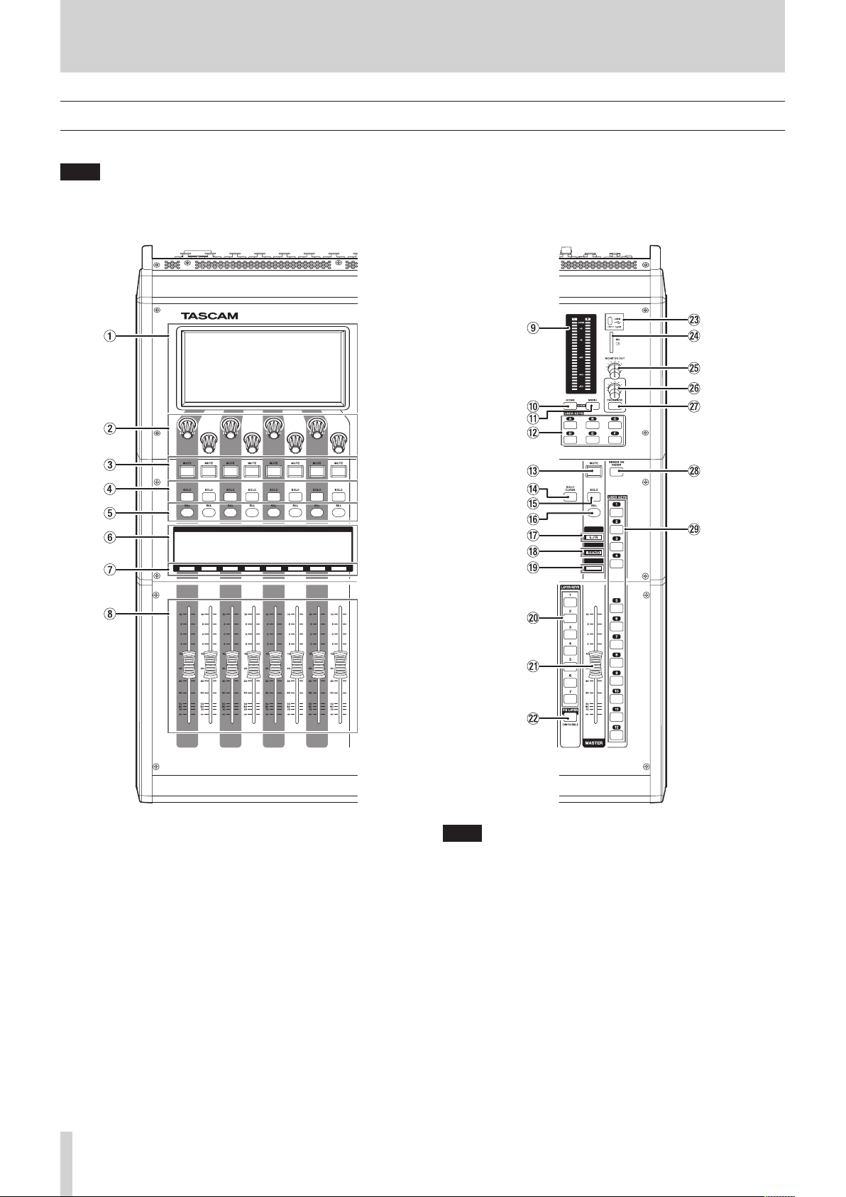
2 – Names and Functions of Parts
Top panel
This section explains the displays and controls on the top panel.
NOTE
The various buttons that have indicators remain dimly lit even when off, making them easier to see and use even in dark situations.
Channel section Master section
1 Touchscreen
o Resistive-type (pressure-sensitive) 800×480 LCD color
touch panels.
o Shows a variety of information.
o Tap and swipe the screens being shown to operate them.
o Only one point on one screen can be operated at a time.
o Set the brightness on the PREFERENCES Screen. (See
“PREFERENCES screen” on page 34.)
2 LCD knobs and indicators
o When LCD knobs can be used to control items shown on
the touchscreen, their indicators light.
o Turn those LCD knobs to adjust various parameters shown
on the touchscreen.
6 TASCAM Sonicview 16/Sonicview 24 V1.1.0
NOTE
i Parameter adjustment with LCD knobs
i Turning an LCD knob without pressing it will change the
parameter value by one step with each click. This enables
precise parameter adjustment.
i When adjusting a parameter with high resolution, turning
an LCD knob while pressing it will change the parameter
value by multiple steps with each click. This enables
efficient parameter adjustment.
i By turning any LCD knob while pressing the HOME key, the
brightness of the touchscreens, channel screens, various
indicators and the lamp connected to the LAMP connector
on the rear panel can all be adjusted at the same time.
i By pressing and turning any LCD knob while pressing the
HOME key, the brightness of the touchscreens and channel
screens can be adjusted at the same time.
i By turning an LCD knob while pressing the MENU key, the
contrast of the channel screen that corresponds to that knob
can be adjusted. (See “12 – List of shortcut operations” on

2 – Names and Functions of Parts
page 206.)
3 MUTE keys and indicators
o These mute/unmute modules assigned to the selected
layer.
o When a MUTE key is on (lit), the signal of the
corresponding module is muted.
o Depending on the DCA or Mute Group, the key will blink
when muted.
o When the SENDS ON FADER key is on (Sends On Fader
mode is on), these turn sends on/off to the selected bus
from the modules assigned to the selected layer (send off
when MUTE button lit, send on when MUTE button unlit).
For modules that do not have a send on/off function
for the subject bus, however, these mute/unmute the
corresponding module. (For example, this applies when
the subject bus is FX1 and the module is FXRTN1 or the
subject bus is MIX1 and the module is MIX1.)
4 SOLO keys and indicators
o These turn soloing on/off for modules assigned to the
selected layer.
o When these keys are on (lit), the signals of the
corresponding modules will be sent to the SOLO L/R bus.
o The keys will blink if soloing is on because of DCA.
NOTE
The MONITOR SETUP screen MONITOR/SOLO page, which is
where various solo settings can be made, can be opened by
pressing this key while pressing the MENU key. (See “Making
monitor output and solo function settings” on page 54.)
(See “12 – List of shortcut operations” on page 206.)
5 SEL keys and indicators
o Press these keys to open the MODULE Screens
for modules assigned to the selected layer. The
corresponding keys light. If the MODULE Screen shown
for a module has been changed on the touchscreen, the
corresponding SEL key will light.
o When a lit SEL key is pressed, the MODULE screen for
that module will be shown on the touchscreen that
corresponds to that SEL key if it is not already shown.
If the MODULE screen for that module is shown on the
touchscreen that corresponds to that SEL key, it will close
and the SEL key will become unlit.
NOTE
Pressing one of these keys while pressing the HOME key will
set the fader level for the corresponding module to 0 dB.
(When Sends On Fader mode is on, the SEND level will be set
instead.) (See “12 – List of shortcut operations” on page 206.)
6 Channel screen
o These show the following information for modules
assigned to the selected layer.
a Module name
b
User module name (name set by user)*
c GATE/EXP/DE-ESSER gain reduction meter
d COMP/DUCKER gain reduction meter
e Module icon*
f Fader level value
g
Module meter (shows signal level of set metering point)
i If the module is stereo, a stereo module meter will
be shown.
i Each module meter has an overload indicator at its
top. They will light when the signal level reaches or
exceeds -0.00026 dBFS (16-bit full-scale value).
i The area below -60 dBFS at the bottom of the
module meters will light when above -70 dBFS.
* See “MODULE NAME screen” on page 160 for details
about setting user module names and module icons.
o When the SENDS ON FADER key is on (Sends On Fader
mode is on), the black and white display is inverted and
“SEND to [bus name]” will be shown on a black band at the
bottom of the screen.
o When the FIX LAYER key (s) has been used to lock 8
channels to the layer, “FIXED LAYER” will be shown on a
white band at the top of the screen.
o When the Sends On Fader mode is on and 8 channels
have been locked to the layer, the black and white display
will be inverted and “SEND to [bus name]” and FIXED
LAYER” will be shown on a black band at the bottom of the
screen.
o Use the PREFERENCES Screen to set the brightness and
contrast of the channel screens. (See “PREFERENCES
screen” on page 34.)
TASCAM Sonicview 16/Sonicview 24 V1.1.0 7

2 – Names and Functions of Parts
7 Channel color bars
These show the colors set for the modules assigned to the
selected layer. (See “Changing set module colors” on page
163.)
8 Channel faders
o When the SENDS ON FADER key is off (Sends On Fader
mode is off), these adjust the fader levels for the modules
assigned to the selected layer.
o When the SENDS ON FADER key is on (Sends On Fader
mode is on), these adjust the send levels to the selected
bus for the modules assigned to the selected layer.
9 Output meters
These are output meters for the MAIN L/R bus.
The OVER indicators light red when they reach or exceed
-0.00026 dBFS (16-bit full-scale value).
The bottommost indicator lights when above -70 dBFS.
0 HOME key
o When the Menu Screen or a settings screen is open, press
to return to the Home Screen on all touchscreens.
o Press and hold this key and the MENU key together for
5 seconds to open the LOCK SETUP screen. (See “LOCK
SETUP screen” on page 39.)
NOTE
Various shortcut operations are possible using this key
in combination with others. See “12 – List of shortcut
operations” on page 206 for details.
q MENU key
o Press this key to open the Menu Screen on the right
touchscreen.
o Press and hold this key and the HOME key together for
5 seconds to open the LOCK SETUP screen. (See “LOCK
SETUP screen” on page 39.)
NOTE
Various shortcut operations are possible using this key
in combination with others. See “12 – List of shortcut
operations” on page 206 for details.
w USER KEY A–F and indicators
Users can assign functions and colors to these keys as
they like. When functions that have different statuses are
assigned to these keys, they will light, blink and become unlit
accordingly. (See “USER DEFINED CONTROLS screen” on page
42.)
e MUTE key and indicator (MASTER)
o This mute/unmutes.
o When the SENDS ON FADER is off (Sends On Fader mode
is off), this mutes the module assigned to the MASTER slot
on the Custom Layer Setup page of the Layer Key Setup
Screen (MAIN L/R by default).
o When the SENDS ON FADER key is on (Sends On Fader
mode is on), this mutes the selected bus master module.
o When a MUTE key is on (lit), the signal of the
corresponding module is muted.
o Depending on the DCA or Mute Group, the key will blink
when muted.
r SOLO CLEAR key and indicator
o The SOLO CLEAR indicator lights when any module is
being soloed.
o Press this when the SOLO CLEAR indicator is lit to end
soloing of all channels.
NOTE
The MONITOR SETUP screen MONITOR/SOLO page can be
opened by pressing this key while pressing the MENU key.
(See “Making monitor output and solo function settings” on
page 54.) (See “12 – List of shortcut operations” on page
206.)
t SOLO key and indicator (MASTER)
o This turns soloing on and off.
o When the SENDS ON FADER is off (Sends On Fader mode
is off), this solos the module assigned to the MASTER slot
on the Custom Layer Setup page of the Layer Key Setup
Screen (MAIN L/R by default).
o When the SENDS ON FADER key is on (Sends On Fader
mode is on), this solos the selected bus master module.
o When this key is on (lit), the signal of the corresponding
module is sent to the SOLO L/R bus.
o The key will blink if soloing is on because of DCA.
NOTE
The MONITOR SETUP screen MONITOR/SOLO page, which is
where various solo settings can be made, can be opened by
pressing this key while pressing the MENU key. (See “Making
monitor output and solo function settings” on page 54.)
(See “12 – List of shortcut operations” on page 206.)
NOTE
Press one of these keys while pressing the MENU key to open
the screen that corresponds to its assigned function. (See “12
– List of shortcut operations” on page 206.)
8 TASCAM Sonicview 16/Sonicview 24 V1.1.0

2 – Names and Functions of Parts
y SEL key and indicator (MASTER)
o When the SENDS ON FADER is off (Sends On Fader mode is
off), this functions as the SEL key for the module assigned
to the MASTER slot on the Custom Layer Setup page of
the Layer Key Setup Screen (MAIN L/R by default).
o When the SENDS ON FADER key is on (Sends On Fader
mode is on), this functions as the SEL key for the selected
bus master module.
o Press this key, lighting it, to open the MODULE screen
for the assigned module on the right touchscreen. If the
MODULE Screen shown for a module has been changed
on the touchscreen, the corresponding SEL key will light.
o When a lit SEL key is pressed, the MODULE screen for
the that module will be shown on the touchscreen that
corresponds to that SEL key if it is not already shown.
If the MODULE screen for that module is shown on the
touchscreen that corresponds to that SEL key, it will close
and the SEL key will become unlit.
NOTE
Pressing this key while pressing the HOME key will set the
fader/send level for the corresponding module to 0 dB. (See
“12 – List of shortcut operations” on page 206.)
u L/R indicator
o When the SENDS ON FADER key is off (Sends On Fader
mode is off) and MAIN L/R is the module assigned to the
MASTER slot on the Custom Layer Setup page of the Layer
Key Setup Screen, the MUTE, SOLO and SEL keys, the color
bar and the MASTER fader in the top panel master section
will control/display the MAIN L/R Master module, and the
indicator will light.
o This indicator will be unlit when the SENDS ON FADER
key is on (Sends On Fader mode is on), as well as when
the SENDS ON FADER key is off and MAIN L/R is not the
module assigned to the MASTER slot on the Custom Layer
Setup page of the Layer Key Setup Screen.
i SEND indicator
o This indicator will be unlit when the SENDS ON FADER key
is off (Sends On Fader mode is off).
o When the SENDS ON FADER key is on (Sends On Fader
mode is on), the MUTE, SOLO and SEL keys, the color bar
and the MASTER fader in the top panel master section will
control/display the SENDS ON FADER operation bus (MIX
1–22/FX 1–4) and the indicator will light.
o Color bar (MASTER)
o When the SENDS ON FADER is off (Sends On Fader mode is
off), this lights with this color set for the module assigned
to the MASTER slot on the Custom Layer Setup page of
the Layer Key Setup Screen (MAIN L/R by default). (See
“Changing set module colors” on page 163.)
o When the SENDS ON FADER key is on (Sends On Fader
mode is on), this lights with the color set for the selected
bus master module. (See “Changing set module colors” on
page 163.)
p LAYER KEY 1–7 and indicators
o Press these keys to switch layers. The last pressed key
will light, showing the current selection. Switching layers
will change the states of module faders, MUTE/SOLO/
SEL keys, channel screens, color bars and touchscreens to
correspond to the current layer.
o The layer assignments of keys and their colors can be set
freely by opening Menu Screen > Front Panel Setup menu
> Layer/Master Fader Setup. (See “Layer Key SETUP page”
on page 50.)
NOTE
The Layer Key SETUP screen for the selected LAYER key can
be opened by pressing that key while pressing the MENU key.
(See “Layer Key SETUP page” on page 50.) (See “12 – List of
shortcut operations” on page 206.)
a MASTER fader
o When the SENDS ON FADER key is off (Sends On Fader
mode is off), this adjusts the fader level of the module
assigned to the MASTER slot on the Custom Layer Setup
page of the Layer Key Setup Screen (MAIN L/R by default).
o When the SENDS ON FADER key is on (Sends On Fader
mode is on), this adjusts the fader level of the selected bus
master module.
s FIX LAYER key and indicator
o While pressing this key, press a SEL key for a block to fix
the corresponding block of 8 channels to the current layer.
This key and the LAYER KEY that corresponds to the fixed
layer will blink. “FIXED LAYER” will be shown on a white
band at the top of the corresponding channel screen.
o While pressing this key, press a SEL key for a block with
a fixed layer to cancel fixing the corresponding block of
8 channels to a layer. This key and the LAYER KEY that
corresponds to the layer that is no longer fixed will stop
blinking. “FIXED LAYER” will stop being shown at the top
of the corresponding channel screen.
o Either the left or right block of 8 channels can be fixed at
a time.
d USB port (5V'0.5A)
This is a USB Type-C port. (This supports USB 2.0.)
o Connect a USB keyboard here, and use it to enter names,
for example. By default, the unit is set to use a Japanese
keyboard. Since English and Japanese keyboards use
different layouts, change the setting on the PREFERENCES
screen if using an English keyboard. (See “PREFERENCES
screen” on page 34.)
o Load a USB flash drive to play files on it, as well as to load
data into and back up data from this unit.
o Mice and other pointing devices are not supported.
f SD card slot
SD cards can be inserted into this slot. (See “Connecting and
disconnecting SD cards and USB flash drives” on page 31.)
Load an SD card to play files on it and record to it, as well as
to load data into and back up data from this unit.
TASCAM Sonicview 16/Sonicview 24 V1.1.0 9
2 – Names and Functions of Parts
g MONITOR OUT volume
Use this to adjust the output level of the MAIN OUTPUT L/R
jacks.
h TALKBACK volume
Use this to adjust the TALKBACK input level.
j TALKBACK key and indicator
o This key turns talkback on and off. Press this key briefly
to switch it on/off. Press this key continuously to turn the
function on only while being pressed.
o The MONITOR SETUP screen TALKBACK/OSCILLATOR page,
which is where various talkback settings can be made, can
be opened by pressing this key while pressing the MENU
key. (See “Making talkback and built-in oscillator settings”
on page 57.) (See “12 – List of shortcut operations” on
page 206.)
k SENDS ON FADER key and indicator
This turns the Sends On Fader mode on/off.
o When the SENDS ON FADER key is on (Sends On Fader
mode is on), this key lights and the unit operates as
follows.
i The SENDS ON FADER screen opens on the rightmost
touchscreen. (See “SENDS ON FADER function” on page
148.)
i This changes the Channel Screens to Send On Fader
mode display.
i The channel faders move to the SEND level positions of
the selected buses.
i The MASTER fader moves to the FADER level position of
the selected bus.
o Press this key when the SENDS ON FADER screen is shown
to end Sends On Fader mode. This will close the SENDS
ON FADER screen and return the channel faders, MASTER
fader and channel screens to their normal display states.
(See “SENDS ON FADER function” on page 148.)
l USER KEY 1–12 and indicators
o Users can assign functions and colors to these keys as
they like. When functions that have different statuses are
assigned to these keys, they will light, blink and become
unlit accordingly. (See “USER DEFINED CONTROLS screen”
on page 42.)
o Press one of these keys while pressing the MENU key to
open the screen that corresponds to its assigned function.
(See “12 – List of shortcut operations” on page 206.)
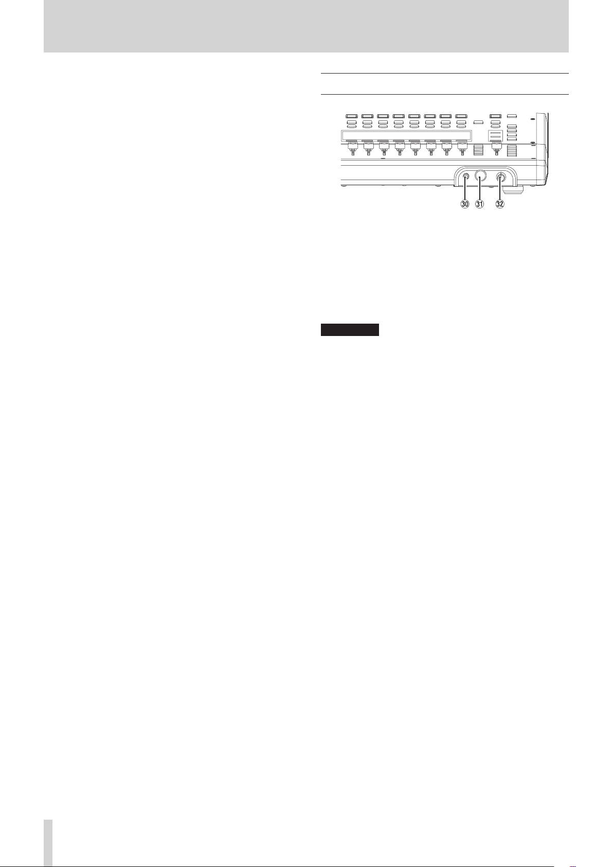
Front panel
; Headphone jack (stereo mini)
Use this 3.5mm (1/8") stereo mini jack to connect stereo
headphones.
z Headphone jack (stereo phone)
Use this 6.3mm (1/4") stereo phone jack to connect stereo
headphones.
x Headphone volume
Use this to adjust the headphone output level.
V
CAUTION
Before connecting headphones, minimize the volume with
the headphone knob. Failure to do so might cause sudden
loud noises, which could harm your hearing or result in other
trouble.
10 TASCAM Sonicview 16/Sonicview 24 V1.1.0

Rear panel
Sonicview 16
2 – Names and Functions of Parts
Sonicview 24
c LAMP jack
Use this to connect a gooseneck lamp to the illuminate the
top of the unit.
Lamps with 4-pin XLR connectors can be used.
Adjust the lamp brightness on the PREFERENCES Screen. (See
“PREFERENCES screen” on page 34.)
o XLR 4-pin female (pin 4: +12V, pin 3: GND)
v MIC/LINE input jacks
These are balanced XLR jacks for mic/line input.
o XLR (1: GND, 2: HOT, 3: COLD)
b LINE IN (BAL) jacks (TRS phone)
These are 6.3mm (1/4") TRS phone jacks for line input.
o TRS (Tip: HOT, Ring: COLD, Sleeve: GND)
NOTE
i This unit has some channels with two types of input jacks
(XLR and TRS). Do not input signals through both the XLR and
TRS jacks of the same channel at the same time. If signals are
input at the same time, they will not be input properly.
i Only MIC/LINE input jacks (v) provide phantom power.
n INSERT jacks (TRS phone)
Use these 6.3mm (1/4") TRS phone jacks to connect external
devices (including effects).
o TRS (Tip: SEND, Ring: RETURN, Sleeve: GND)
m TALKBACK input jack
o Connect a talkback mic here.
o Use the TALKBACK volume knob (h) to adjust the
talkback input level, and use the TALKBACK key (j) to
turn it on/off.
o Make talkback settings on the MONITOR SETUP screen
TALKBACK/OSCILLATOR page. (See “Making talkback and
built-in oscillator settings” on page 57.)
TASCAM Sonicview 16/Sonicview 24 V1.1.0 11

2 – Names and Functions of Parts
, Analog output jacks
These analog outputs are XLR jacks.
o XLR (1: GND, 2: HOT, 3: COLD)
. Dante PRIMARY connector
This is the main etherCON Cat5e-compatible Dante
transmission connector.
Use this to connect to a Dante network all the time.
Make settings for the built-in Dante module on the Dante
SETUP Screen. (See “Dante SETUP screen” on page 58.)
/ Dante SECONDARY connector
This is the secondary etherCON Cat5e-compatible Dante
transmission connector. The use changes depending on the
mode.
When in redundant mode, this connects to the secondary
Dante network.
When in switched (daisy-chain) mode, use this to connect
another Dante device in the chain.
Make settings for the built-in Dante module on the Dante
SETUP Screen. (See “Dante SETUP screen” on page 58.)
! Expansion card slots (SLOT 1/SLOT 2)
These slots can be used to install expansion cards (sold
separately).
Make SLOT settings on the SLOT SETUP Screen. (See “SLOT
SETUP screen” on page 88.)
@ WORD THRU/OUT connector
This BNC connector is for word clock output.
Use it for thru and normal output of word clock signals.
Switch word thru/output on the SYNC CLOCK Screen. (See
“SYNC CLOCK screen” on page 32.)
# WORD IN connector
This BNC connector is for word clock input.
Use it for word clock signal input.
Connect a word clock signal to this connector when
synchronizing the word clock of this unit and other
equipment.
$ FOOTSWITCH jack
This 6.3mm (1/4") TS phone jack is for connecting a
footswitch.
Set functions assigned to the footswitch on the USER
DEFINED CONTROL Screen Foot Switch page. (See “Foot
Switch page” on page 48.)
o TS (Tip: HOT, Sleeve: GND)
% USB to PC port
This is a USB Type-B port.
Use a USB cable (Type-A to Type-B) to connect the unit to a
computer.
ATTENTION
The unit should be connected directly to the computer, not
through a USB hub. Moreover, proper transmission with a
computer could fail if the cable is too long.
^ ETHERNET port
This is an Ethernet port.
Use this to connect to a network, primarily for the purpose
of remote control of this unit using the dedicated TASCAM
Sonicview Control application.
Make network settings on the Network Setup Screen. (See
“Network Setup screen” on page 90.)
For details about the TASCAM Sonicview Control application,
see its manual. You can download the application manual
from the TEAC Global Site (https://teac-global.com/).
& GPIO connector
This is a 25-pin D-sub Parallel control input/output connector.
It can send and receive control commands with 8 inputs and
8 outputs. See “GPIO connector overview” on page 13 for
details about pin assignments.
Set functions assigned to the GPIO input connector on the
USER DEFINED CONTROL Screen GPIO-IN page. (See “GPIO-IN
page” on page 48.)
Set functions assigned to the GPIO output connector on the
USER DEFINED CONTROL Screen GPIO-OUT page. (See “GPIOOUT page” on page 49.)
* MONITOR OUT L/R jacks
These analog outputs are XLR jacks.
Make monitor output settings on the MONITOR SETUP screen
MONITOR/SOLO page. (See “Making monitor output and solo
function settings” on page 54.)
o XLR (1: GND, 2: HOT, 3: COLD)
( ST IN 1/ST IN 2 jacks
These RCA pin jacks are analog line outputs.
Use RCA cables to connect CD players and similar devices to
these jacks.
) POWER switch
This turns the power on/off.
V
CAUTION
Before turning the power on or off, minimize the volumes of
connected equipment. Failure to do so might cause sudden
loud noises, which could harm your hearing or result in other
trouble.
NOTE
i Do not interrupt the power when the unit is operating
(including recording, playing back, or writing data to an
SD card or USB flash drive). Doing so could cause proper
recording to fail and recorded data to be lost.
i We recommend executing the Save Current Settings
command on the Menu Screen before turning the unit off.
(See “Saving the current settings” on page 92.)
Q AC IN connector
Plug the included power cord in here.
12 TASCAM Sonicview 16/Sonicview 24 V1.1.0

2 – Names and Functions of Parts
GPIO connector overview
The GPIO connector on the back of the unit is a parallel control connector that allows this unit to control and be controlled by other
devices.
GPIO connector function settings can be changed on the USER DEFINED CONTROLS Screen GPIO-IN and GPIO-OUT pages. (See “USER
DEFINED CONTROLS screen” on page 42.)
The pin assignments are as follows.
Pin No. Function IN/OUT
1 GND -
2 GPIO IN 2 IN
3 GPIO IN 4 IN
4 GPIO IN 6 IN
5 GPIO IN 8 IN
6 NC -
7 NC -
8 NC -
9 GPIO OUT 2 OUT
10 GPIO OUT 4 OUT
11 GPIO OUT 6 OUT
12 GPIO OUT 8 OUT
13 NC -
14 GPIO IN 1 IN
15 GPIO IN 3 IN
16 GPIO IN 5 IN
17 GPIO IN 7 IN
18 NC -
19 NC -
20 GND -
21 GPIO OUT 1 OUT
22 GPIO OUT 3 OUT
23 GPIO OUT 5 OUT
24 GPIO OUT 7 OUT
25 +5V -
IN: For command input
i Internal circuit with +5V pull-up
i Operates with low signal input of 50 msec or longer
OUT: For command and tally output
i Internal circuit is open collector (10Ω output impedance)
i 20V dielectric strength, 35mA maximum current
+5V: 50mA maximum supplied current
TASCAM Sonicview 16/Sonicview 24 V1.1.0 13

2 – Names and Functions of Parts
Basic unit operations
Touchscreen operations
Tap/swipe items on the touchscreens to operate them.
Special touchscreen operations
Touch continuously Touch the +48V button continuously to turn phantom power (+48V) on and off.
Tapping the DIMMER button on the MONITOR/SOLO page of the MONITOR SETUP screen, or tapping
Tap/touch continuously
the TALKBACK button on the TALKBACK/OSCILLATOR page will turn that function on/off. Touching it
continuously will turn it on temporarily until released.
Return to previous screen
Open pull-down menu
Open Settings ScreenScreen name
LCD knobs and indicators
Switch to Home Screen
LCD knob operations
The LCD knobs can be used to control the parameters shown and selected above them on the touchscreen.
When LCD knobs can be used, the corresponding indicators light.
LCD knob Explanation
Turn without pressing This allows precise adjustment of one step per click.
Turn while pressing This allows quick parameter adjustment from one extreme to the other.
Top panel key operations
Press keys on the top panel to use them.
The following keys have special operation procedures.
Key Use
TALKBACK key
HOME key + MENU key Press and hold the HOME and MENU keys together for 5 seconds to open the LOCK SETUP Screen.
NOTE
The parameters of this unit have unified image colors, making identification of parameter types easy by color.
i GAIN/Level: Red
i GATE: Yellow-green
i EQ: Blue
i COMP: Green
i FX: Yellow-green
i AUX mode bus: Orange
i GROUP mode bus: Purple
i PAN: Yellow
i FADER: Light blue
Press this key briefly to turn talkback on/off.
Press this key continuously to turn the function on only while being pressed.
14 TASCAM Sonicview 16/Sonicview 24 V1.1.0

2 – Names and Functions of Parts
Home Screen
This unit has multiple Home Screens for its layers. The names
of modules assigned to layers, various parameters, meters and
other items are shown in lists.
Press LAYER KEY 1–7 to change what is shown on the Home
Screen.
NOTE
When the Menu Screen or a settings screen is open, press the
HOME key to return to the Home Screen.
CH 1–40 Module Home Screen
CH 1–40 Module Home Screen
1 INPUT area
o This shows the input settings of the selected input source.
(A stereo module is shown on the right.)
Input area display when the input source is “ANALOG” or “SB-16D
connected by built-in Dante”
Input area display when the input source is not “ANALOG” or “SB-
16D connected by built-in Dante”
a This shows the input source name.
i If a Dante port that has a mounted SB-16D assigned
is selected, “SB#[ID] [port number]” will be shown.
CH 1–40 Module Home Screen details
If it is a virtually-mounted SB-16D, will appear to
the bottom left of the port name.
i If the module is stereo and input sources that
are not left-right adjacent are selected, input
source names will appear split left and right and
abbreviated as follows.
Input source
name
ANALOG AN
Dante DA
SLOT 1 S1
USB US
ST IN 1 ST1
PLAYER PL
Input source name
abbreviation
TASCAM Sonicview 16/Sonicview 24 V1.1.0 15

2 – Names and Functions of Parts
i When a module is stereo, if a Dante port that has a
mounted SB-16D assigned is selected, “#[ID] [port
number]” will be shown.
If it is a virtually-mounted SB-16D, the # background
will be yellow.
b These indicators appear to light as shown below
depending on the input level. When a module is stereo,
two sets of module indicators will be shown separately
left and right.
Red: -3 dBFS, Green: -40 dBFS
c This shows the input signal phase setting status. When
a module is stereo, two module phase settings will be
shown separately left and right.
Normal
Reversed
d
This shows the -20dB pad setting status when the input
source of the selected module is
connected by built-in Dante”. When on, the icon will
appear highlighted.
If the input sources for both the left and right channels
of a stereo module are “ANALOG” or “SB-16D connected
by built-in Dante”, this shows the left channel setting.
e This shows the phantom power (+48V) setting status
when the input source of the selected module is
“ANALOG” or “SB-16D connected by built-in Dante”.
When on, the icon will appear highlighted.
If the input sources for both the left and right channels
of a stereo module are “ANALOG” or “SB-16D connected
by built-in Dante”, this shows the left channel setting.
f This shows the HPF setting status. When on, the icon
will appear highlighted.
g When the input source of the selected module is
“ANALOG” or “SB-16D connected by built-in Dante”,
this will show an analog gain knob and the input level
of the unit or SB-16D MIC/LINE input jacks. When a
module is stereo, two knobs and input level values will
be shown for the module.
A black knob that cannot be operated will be shown
if the input source is an SB-16D for which control
privileges are not held.
h A D.TRIM knob and the digital trim value will be shown
when the input source of the selected module is not
“ANALOG” or “SB-16D connected by built-in Dante”.
o Tap this area to show the selection frame. When the
selection frame is shown, corresponding LCD knobs can
be used to adjust the parameters shown.
“ANALOG” or
“SB-16D
o When the selection frame is shown, tap this area to open
the MODULE (INPUT) Screen for the selected module. (See
“MODULE (INPUT) Screen” on page 124.)
2 GATE/EXPANDER/DE-ESSER area
o This shows the response graphs and gain reduction
meters of dynamics effects.
o Tap this area to open the MODULE (GATE/EXPANDER/
DE-ESSER) Screen for the selected module. (See “MODULE
(GATE/EXPANDER/DE-ESSER) screens” on page 132.)
3 HPF/EQ area
o This shows graphs of the HPF and EQ frequency
responses.
o Tap this area to open the MODULE (EQ) Screen for the
selected module. (See “MODULE (EQ) Screen” on page
134.)
4 COMP/DUCKER area
o This shows the response graphs and gain reduction
meters of dynamics effects.
o Tap this area to open the MODULE (COMP/DUCKER) Screen
for the selected module. (See “MODULE (COMP/DUCKER)
Screen” on page 138.)
5 Level meters
This shows the level of the signal at the set metering point.
(See “METERING POINT page” on page 38.) (See “MODULE
(OVERVIEW) Screen” on page 112.)
NOTE
i If the selected module is stereo, a stereo level meter will be
shown.
i Each level meter has an overload indicator at its top. They will
appear to light red when the signal level reaches or exceeds
-0.00026 dBFS (16-bit full-scale value).
i When a level overload occurs, the entire bar meter will light
red.
i The area below -60 dBFS at the bottom of the level meters
will light when above -70 dBFS.
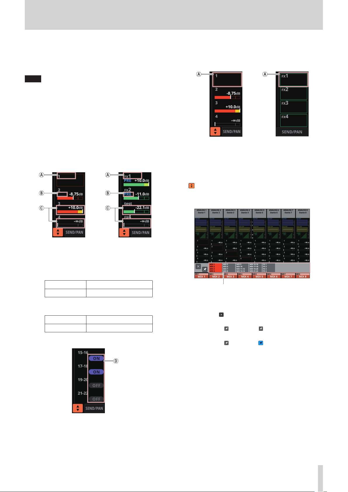
6 SEND area
o This shows the states of SEND settings to MIX 1–22 and FX
1–4 buses 4 at a time.
a This shows the user module name for the MIX 1–22 or
FX RTN 1–4 module. If the name has not been defined,
the module name will be shown as “1” or “FX 1”, for
example.
b This shows the PRE/POST setting used for MIX 1–22
and FX 1–4 buses.
No indicator Set to POST
PRE Set to PRE
16 TASCAM Sonicview 16/Sonicview 24 V1.1.0

2 – Names and Functions of Parts
c These show the assignment state and send level to MIX
1–22 and FX 1–4 buses in AUX mode.
MIX 1–22 bus Shown in orange
FX 1–4 bus Shown in green
This will be gray when not assigned.
d Purple rounded buttons are shown when GROUP mode
MIX 1–22 buses are ON. These appear but cannot be
turned on/off on the Home Screen.
o Tap a SEND level to show the selection frame. When the
selection frame is shown, corresponding LCD knobs can
be used to adjust the SEND level shown.
o Tap the SEND level while pressing the HOME key to set the
SEND level for that bus to 0 dB. (See “12 – List of shortcut
operations” on page 206.)
7 button
Tap this button to show the selection window for the bus
shown in the SEND area.
9 ALL SEND button ( )
Tap this button to change the SEND area display to ALL SEND
bus display.
a These show the assignment state and send level to MIX
1–22 and FX 1–4 buses in AUX mode.
MIX 1–22 bus Shown in orange
FX 1–4 bus Shown in green
bus selection button
i Tap a bus selection button to open the selected bus
group in the SEND area.
i Tap the button at the top left of the selection
window to close it.
i When the button is off ( ), tapping the bus selection
button will automatically close this window.
i When the button is on ( ), tapping a bus selection
button will not close this window.
8 SEND/PAN button
Tap this button to open the MODULE (SEND/PAN) Screen.
(See “MODULE (SEND/PAN) Screen” on page 140.)
This will be gray when not assigned.
b When the selection frame is shown, corresponding LCD
knobs can be used to adjust the SEND levels shown.
The selection frame can also be swiped up and down
to select MIX 1–22 and FX 1–4 buses.
c These show the assignment state and send level to MIX
1–22 buses in GROUP mode. These appear but cannot
be adjusted.
OFF Shown in dark purple
ON Shown in bright purple
d These appear light blue when the PRE/POST setting
used for MIX 1–22 and FX 1–4 buses is “PRE”.
o Tap the ALL SEND bus area to switch to showing 4 buses
in the tapped area.
0 PAN area
o This shows the pan/balance setting of the signals sent to
the MAIN L/R bus as well as the MAIN L/R bus assignment
status.
o Tap this area to show the selection frame. When the
selection frame is shown, corresponding LCD knobs can
be used to adjust the pan/balance of the sent signals.
o Tap this area while pressing the HOME key to set the
tapped pan/balance setting to center (C). (See “12 – List of
shortcut operations” on page 206.)
o When the selection frame is shown, tap this area to open
the MODULE (SEND/ PAN) Screen. (See “MODULE (SEND/
PAN) Screen” on page 140.)
TASCAM Sonicview 16/Sonicview 24 V1.1.0 17
2 – Names and Functions of Parts
q NAME area
o The module name is shown at the top left.
o At the top right, the Mute Group assignment status is
shown in the top line and the DCA assignment status
is shown in the bottom line. Red numbers show the
assigned Mute Group numbers. Yellow numbers show the
assigned DCA numbers.
See “Mute Group Assign page” on page 159 and
“MODULE (OVERVIEW) Screen” on page 112 for changing
Mute Group assignments.
See “DCA Assign page” on page 158 and “MODULE
(OVERVIEW) Screen” on page 112 for changing DCA
assignments.
o The bottom line shows the user module name (name set
by user). If the name has not been defined, the module
name will be shown as “CH 1”, for example. See “Setting
and editing user module names” on page 161 for details
about setting user module names.
o The NAME area background color is the color set for the
assigned module. See “Changing set module colors” on
page 163 to change set module colors.
o Tap this area to open the MODULE (OVERVIEW) Screen.
(See “MODULE (OVERVIEW) Screen” on page 112.)
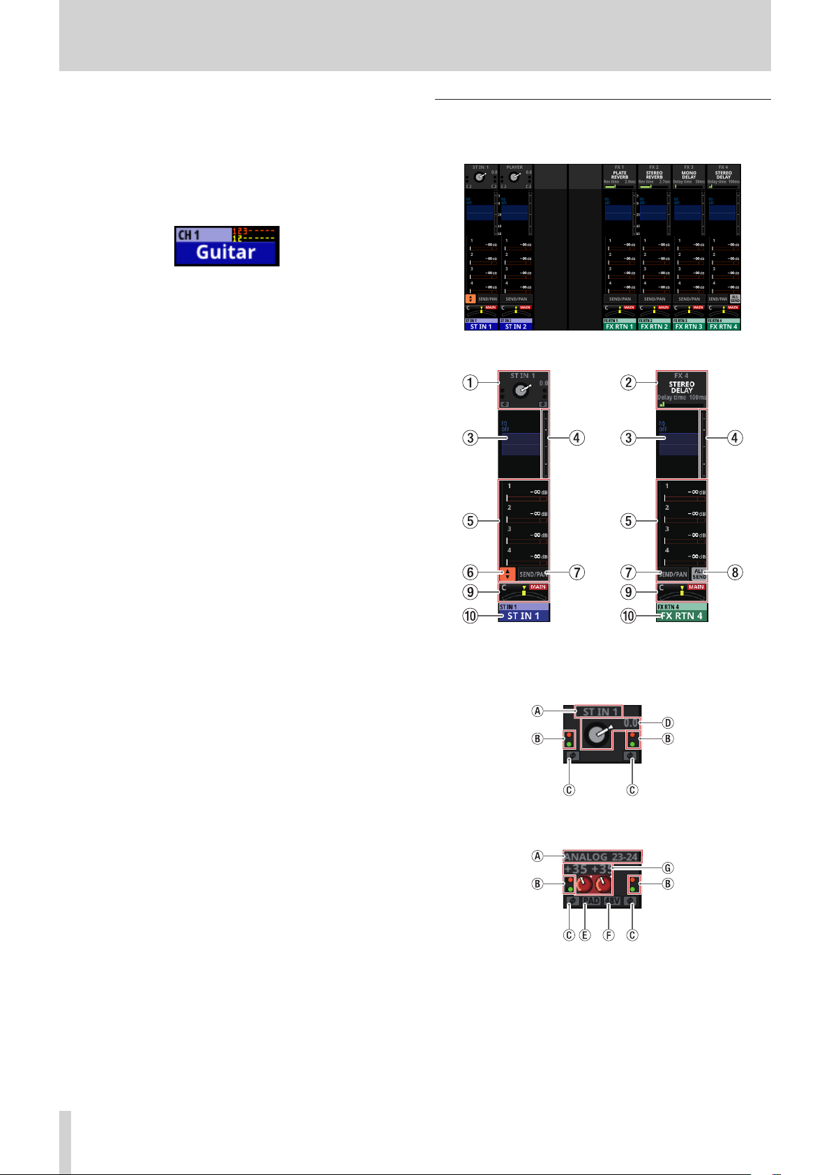
ST IN 1–2/FX RTN 1–4 Module Home Screen
ST IN 1–2/FX RTN 1–4 Module Home Screen
ST IN 1–2/FX RTN 1–4 Module Home Screen details
1 INPUT area
o This shows the input settings of the selected input source.
Input area display when the input source is not “ANALOG” or “SB-
Input area display when the input source is “ANALOG” or “SB-16D
16D connected by built-in Dante”
connected by built-in Dante”
18 TASCAM Sonicview 16/Sonicview 24 V1.1.0

2 – Names and Functions of Parts
a This shows the input source name.
i If a Dante port that has a mounted SB-16D assigned
is selected, “SB#[ID] [port number]” will be shown.
If it is a virtually-mounted SB-16D, will appear to
the bottom left of the port name.
i If the module is stereo and input sources that
are not left-right adjacent are selected, input
source names will appear split left and right and
abbreviated as follows.
d A D.TRIM knob and the digital trim value will be shown
when the input source of the selected module is not
“ANALOG” or “SB-16D connected by built-in Dante”.
e
This shows the -20dB pad setting status when the input
source of the selected module is
connected by built-in Dante”. When on, the icon will
appear highlighted.
If the input sources for both the left and right channels
of a stereo module are “ANALOG” or “SB-16D connected
by built-in Dante”, this shows the left channel setting.
f This shows the phantom power (+48V) setting status
when the input source of the selected module is
“ANALOG” or “SB-16D connected by built-in Dante”.
When on, the icon will appear highlighted.
If the input sources for both the left and right channels
of a stereo module are “ANALOG” or “SB-16D connected
by built-in Dante”, this shows the left channel setting.
g When the input source of the selected module is
“ANALOG” or “SB-16D connected by built-in Dante”,
this will show 2 analog gain knobs and the input level
values of the unit or
A black knob that cannot be operated will be shown
if the input source is an SB-16D for which control
privileges are not held.
SB-16D
“ANALOG” or
MIC/LINE input jacks.
“SB-16D
Input source
name
ANALOG AN
Dante DA
SLOT 1 S1
USB US
ST IN 1 ST1
PLAYER PL
i When a module is stereo, if a Dante port that has a
mounted SB-16D assigned is selected, “#[ID] [port
number]” will be shown.
If it is a virtually-mounted SB-16D, the # background
will be yellow.
Input source name
abbreviation
o Tap this area to show the selection frame. When the
selection frame is shown, corresponding LCD knobs can
be used to adjust the parameters shown.
o When the selection frame is shown, tap this area to open
the MODULE (INPUT) Screen for the selected module. (See
“MODULE (INPUT) Screen” on page 124.)
2 FX area
o This shows effects names and main effect parameters.
o Tap this area to show the selection frame. When the
selection frame is shown, corresponding LCD knobs can
be used to adjust effect parameters shown.
o When the selection frame is shown, tap this area to open
the MODULE (FX) Screen for the selected module. (See
“MODULE (FX) Screen” on page 128.)
3 EQ area
o This shows a graph of the EQ frequency response.
o Tap this area to open the MODULE (EQ) Screen for the
selected module. (See “MODULE (EQ) Screen” on page
134.)
b These indicators appear to light as shown below
depending on the input level.
Red: -3 dBFS, Green: -40 dBFS
c This shows the input signal phase setting status.
Normal
Reversed
TASCAM Sonicview 16/Sonicview 24 V1.1.0 19

2 – Names and Functions of Parts
4 Level meters
This shows the level of the signal at the set metering point.
(See “METERING POINT page” on page 38.) (See “ST IN 1–2
MODULE (OVERVIEW) Screens” on page 117.) (See “FX RTN
1–4 MODULE (OVERVIEW) Screens” on page 120.)
NOTE
i The ST IN 1–2/FX RTN 1–4 modules are stereo, so stereo level
meters are shown.
i Each level meter has an overload indicator at its top. They will
appear to light red when the signal level reaches or exceeds
-0.00026 dBFS (16-bit full-scale value).
i When a level overload occurs, the entire bar meter will light
red.
i The area below -60 dBFS at the bottom of the level meters
will light when above -70 dBFS.
5 SEND area
o This shows the states of SEND settings to MIX 1–22 and FX
1–4 buses 4 at a time.
¦b, c and d are not shown in the FX 1–4 area of the FX
RTN module.
o Tap a SEND level to show the selection frame. When the
selection frame is shown, corresponding LCD knobs can
be used to adjust the SEND level shown.
o Tap the SEND level while pressing the HOME key to set the
SEND level for that bus to 0 dB. (See “12 – List of shortcut
operations” on page 206.)
6 button
Tap this button to show the selection window for the bus
shown in the SEND area.
a This shows the user module name for the MIX 1–22 or
FX RTN 1–4 module. If the name has not been defined,
the module name will be shown as “1” or “FX 1”, for
example.
b This shows the PRE/POST setting used for MIX 1–22
and FX 1–4 buses.
No indicator Set to POST
PRE Set to PRE
c These show the assignment state and send level to MIX
1–22 and FX 1–4 buses in AUX mode.
MIX 1–22 bus Shown in orange
FX 1–4 bus Shown in green
This will be gray when not assigned.
bus selection button
i Tap a bus selection button to open the selected bus
group in the SEND area.
i Tap the button at the top left of the selection
window to close it.
i When the button is off ( ), tapping the bus selection
button will automatically close this window.
i When the button is on ( ), tapping a bus selection
button will not close this window.
7 SEND/PAN button
Tap this button to open the MODULE (SEND/PAN) Screen.
(See “MODULE (SEND/PAN) Screen” on page 140.)
d Purple rounded buttons are shown when GROUP mode
MIX 1–22 buses are ON. These appear but cannot be
turned on/off on the Home Screen.
20 TASCAM Sonicview 16/Sonicview 24 V1.1.0

2 – Names and Functions of Parts
8 ALL SEND button ( )
Tap this button to change to the ALL SEND bus display.
a These show the assignment state and send level to MIX
1–22 and FX 1–4 buses in AUX mode.
0 NAME area
o The module name is shown at the top left.
o At the top right, the Mute Group assignment status is
shown in the top line and the DCA assignment status
is shown in the bottom line. Red numbers show the
assigned Mute Group numbers. Yellow numbers show the
assigned DCA numbers.
See “Mute Group Assign page” on page 159 and
“MODULE (OVERVIEW) Screen” on page 112 for changing
Mute Group assignments.
See “DCA Assign page” on page 158 and “MODULE
(OVERVIEW) Screen” on page 112 for changing DCA
assignments.
o The bottom line shows the user module name (name set
by user). If the name has not been defined, the module
name will be shown as “ST IN 1” or “FX RTN 1”, for example.
See “Setting and editing user module names” on page
161 for details about setting user module names.
o The NAME area background color is the color set for the
assigned module. See “Changing set module colors” on
page 163 to change set module colors.
o Tap this area to open the MODULE (OVERVIEW) Screen.
(See “ST IN 1–2 MODULE (OVERVIEW) Screens” on page
117.)
MIX 1–22 bus Shown in orange
FX 1–4 bus Shown in green
This will be gray when not assigned.
b When the selection frame is shown, corresponding LCD
knobs can be used to adjust the SEND levels shown.
The selection frame can also be swiped up and down
to select MIX 1–22 and FX 1–4 buses.
c These show the assignment state and send level to MIX
1–22 buses in GROUP mode. These appear but cannot
be adjusted.
OFF Shown in dark purple
ON Shown in bright purple
d These appear light blue when the PRE/POST setting
used for MIX 1–22 and FX 1–4 buses is “PRE”.
o Tap the ALL SEND bus area to switch to showing 4 buses
in the tapped area.
9 PAN area
o This shows the pan/balance setting of the signals sent to
the MAIN L/R bus as well as the MAIN L/R bus assignment
status.
o Tap this area to show the selection frame. When the
selection frame is shown, corresponding LCD knobs can
be used to adjust the pan/balance of the sent signals.
o Tap this area while pressing the HOME key to set the
tapped pan/balance setting to center (C). (See “12 – List of
shortcut operations” on page 206.)
o When the selection frame is shown, tap this area to open
the MODULE (SEND/ PAN) Screen. (See “MODULE (SEND/
PAN) Screen” on page 140.)
TASCAM Sonicview 16/Sonicview 24 V1.1.0 21

2 – Names and Functions of Parts
MIX 1–22 and MAIN L/R Master Module Home Screen
MIX 1–22 and MAIN L/R Master Module Home Screen
i If the module is stereo, output port names will appear
split left and right and abbreviated as follows.
Output port
name
ANALOG AN
Dante DA
SLOT 1 S1
USB US
i When a module is stereo, if a Dante port that has a
mounted SB-16D assigned is selected, “#[ID] [port
number]” will be shown.
If it is a virtually-mounted SB-16D, the # background
will be yellow.
Output port name
abbreviatio
MIX 1–22 and MAIN L/R Master Module Home Screen details
1 OUTPUT area
o This shows the output port assignment status.
i If a Dante port that has a mounted SB-16D assigned is
selected, “SB#[ID] [port number]” will be shown.
If it is a virtually-mounted SB-16D, will appear to the
left of the port name.
o Tap this area to open the MODULE (OUTPUT) Screen for
the selected module. (See “MODULE (OUTPUT) Screen” on
page 144.)
2 EQ area
o This shows a graph of the EQ frequency response.
o Tap this area to open the MODULE (EQ) Screen for the
selected module. (See “MODULE (EQ) Screen” on page
134.)
3 GEQ area
o This shows a graph of the GEQ frequency response.
o Tap this area to open the MODULE (GEQ) Screen for the
selected module. (See “MODULE (GEQ) Screen” on page
136.)
4 COMP/DUCKER area
o This shows the response graphs and gain reduction
meters of dynamics effects.
o Tap this area to open the MODULE (COMP/DUCKER)
Screen for the selected module. (See “MODULE (COMP/
DUCKER) Screen” on page 138.)
22 TASCAM Sonicview 16/Sonicview 24 V1.1.0
2 – Names and Functions of Parts
5 Level meters
This shows the level of the signal at the set metering point.
(See “METERING POINT page” on page 38.) (See “MIX 1–22
and MAIN L/R Master MODULE (OVERVIEW) Screens” on page
121.)
NOTE
i If the selected module is stereo, a stereo level meter will be
shown.
i Each level meter has an overload indicator at its top. They will
appear to light red when the signal level reaches or exceeds
-0.00026 dBFS (16-bit full-scale value).
i When a level overload occurs, the entire bar meter will light
red.
i The area below -60 dBFS at the bottom of the level meters
will light when above -70 dBFS.
6 SEND area
o This shows the states of SEND settings to MIX 1–22 and FX
1–4 buses 4 at a time.
¦b, c and d are not shown in the bus areas of the
corresponding modules themselves. b, c and d are
also not shown in the FX 1–4 area of the MAIN L/R
Master module.
o Tap a SEND level to show the selection frame. When the
selection frame is shown, corresponding LCD knobs can
be used to adjust the SEND level shown.
o Tap the SEND level while pressing the HOME key to set the
SEND level for that bus to 0 dB. (See “12 – List of shortcut
operations” on page 206.)
7 button
Tap this button to show the selection window for the bus
shown in the SEND area.
a This shows the user module name for the MIX 1–22 or
FX RTN 1–4 module. If the name has not been defined,
the module name will be shown as “1” or “FX 1”, for
example.
b This shows the PRE/POST setting used for MIX 1–22
and FX 1–4 buses.
No indicator Set to POST
PRE Set to PRE
c These show the assignment state and send level to MIX
1–22 and FX 1–4 buses in AUX mode.
MIX 1–22 bus Shown in orange
FX 1–4 bus Shown in green
This will be gray when not assigned.
bus selection button
i Tap a bus selection button to open the selected bus
group in the SEND area.
i Tap the button at the top left of the selection
window to close it.
i When the button is off ( ), tapping the bus selection
button will automatically close this window.
i When the button is on ( ), tapping a bus selection
button will not close this window.
8 SEND/PAN button
Tap this button to open the MODULE (SEND/PAN) Screen.
(See “MODULE (SEND/PAN) Screen” on page 140.)
d Purple rounded buttons are shown when GROUP mode
MIX 1–22 buses are ON. These appear but cannot be
turned on/off on the Home Screen.
TASCAM Sonicview 16/Sonicview 24 V1.1.0 23

2 – Names and Functions of Parts
9 ALL SEND button ( )
Tap this button to change to the ALL SEND bus display.
a These show the assignment state and send level to MIX
1–22 and FX 1–4 buses in AUX mode.
q NAME area
o The module name is shown at the top left.
o At the top right, the Mute Group assignment status is
shown in the top line and the DCA assignment status
is shown in the bottom line. Red numbers show the
assigned Mute Group numbers. Yellow numbers show the
assigned DCA numbers.
See “Mute Group Assign page” on page 159 and
“MODULE (OVERVIEW) Screen” on page 112 for changing
Mute Group assignments.
See “DCA Assign page” on page 158 and “MODULE
(OVERVIEW) Screen” on page 112 for changing DCA
assignments.
o The bottom line shows the user module name (name set
by user). If the name has not been defined, the module
name will be shown as “MIX 1”, for example. See “Setting
and editing user module names” on page 161 for details
about setting user module names.
o The NAME area background color is the color set for the
assigned module. See “Changing set module colors” on
page 163 to change set module colors.
o Tap this area to open the MODULE (OVERVIEW)
Screen. (See “MIX 1–22 and MAIN L/R Master MODULE
(OVERVIEW) Screens” on page 121.)
MIX 1–22 bus Shown in orange
FX 1–4 bus Shown in green
This will be gray when not assigned.
b When the selection frame is shown, corresponding LCD
knobs can be used to adjust the SEND levels shown.
The selection frame can also be swiped up and down
to select MIX 1–22 and FX 1–4 buses.
c These show the assignment state and send level to MIX
1–22 buses in GROUP mode. These appear but cannot
be adjusted.
OFF Shown in dark purple
ON Shown in bright purple
d These appear light blue when the PRE/POST setting
used for MIX 1–22 and FX 1–4 buses is “PRE”.
o Tap the ALL SEND bus area to switch to showing 4 buses
in the tapped area.
0 PAN area (MIX 1–22 modules only)
o This shows the pan/balance setting of the signals sent to
the MAIN L/R bus as well as the MAIN L/R bus assignment
status.
o Tap this area to show the selection frame. When the
selection frame is shown, corresponding LCD knobs can
be used to adjust the position/balance of the sent signals.
o Tap this area while pressing the HOME key to set the
tapped pan/balance setting to center (C). (See “12 – List of
shortcut operations” on page 206.)
o When the selection frame is shown, tap this area to open
the MODULE (SEND/ PAN) Screen. (See “MODULE (SEND/
PAN) Screen” on page 140.)
24 TASCAM Sonicview 16/Sonicview 24 V1.1.0

2 – Names and Functions of Parts
DCA Module Home Screen
DCA Module Home Screen
2 NAME area
o The module name is shown at the top left.
o At the top right, the Mute Group assignment status is
shown in the top line and the DCA assignment status
is shown in the bottom line. Red numbers show the
assigned Mute Group numbers. Yellow numbers show the
assigned DCA numbers.
See “Mute Group Assign page” on page 159 for changing
Mute Group assignments.
See “DCA Assign page” on page 158 for changing DCA
assignments.
o The bottom line shows the user module name (name set
by user). If the name has not been defined, the module
name will be shown as “DCA 1”, for example. See “Setting
and editing user module names” on page 161 for details
about setting user module names.
o The NAME area background color is the color set for the
assigned module. See “Changing set module colors” on
page 163 to change set module colors.
o Tap this area to open the MODULE NAME Screen where
the user module name and set module color can be
changed. (See “MODULE NAME screen” on page 160.)
DCA Module Home Screen details
1 DCA assignment display area
o This shows the names and-user module names of
modules that have been assigned to the corresponding
DCAs.
o Tap this area to open the DCA/Mute Group SETUP Screen
DCA Assign page. (See “DCA Assign page” on page 158.)
TASCAM Sonicview 16/Sonicview 24 V1.1.0 25

2 – Names and Functions of Parts
Menu Screen
Open various settings screens and use snapshot functions from
this screen.
Press the MENU key to open this on the right touchscreen.
1 Snapshot function area
This shows items related to the snapshot function.
See “Snapshot functions” on page 164 for details about the
snapshot function.
2 Menu item area
This shows menu items.
Tap a menu item to show its submenu items.
3 Submenu item area
This shows submenu items. If the submenu has 9 or more
items, swipe the submenu area up and down to scroll it.
Tap a submenu item to open a settings screen.
4 button
Tap this button to close the Menu Screen.
Menu Screen operations
In this example, will open the TALKBACK Setup Screen.
1. Press the MENU button to switch to the Menu Screen.
NOTE
When the Menu Screen is opened the first time after startup,
submenu items will not be shown.
2. Tap “Front Panel Setup” in the menu item area to show its
submenu items.
3. Tap “Talkback Setup” to open the MONITOR SETUP screen
TALKBACK/OSCILLATOR page.
26 TASCAM Sonicview 16/Sonicview 24 V1.1.0

2 – Names and Functions of Parts
Menu structure
The following is an overview of the various menu items.
Menu item Sub menu item Functions Page
View various meters and set various meter display
parameters
Make the following settings
i DCA assignments
i Mute Group assignments
i Turn Mute Group Master on/off
Make the following settings
i CH 1–40 stereo link settings
i DIRECT OUT POINT settings
i DELAY POINT settings
i INSERT POINT unified settings
i BUS MODE settings
i MIX 1–22 stereo link settings
i Pan link settings
Make the following settings
i Assign channel sets and custom layers to the 7 LAYER
KEYS
i Assign module groups to custom layers
i Assign modules to the MASTER fader
Set and view the status of the built-in Dante module and an
SB-16D connected via the built-in Dante module
Set various functions of expansion cards loaded in SLOT 1
and SLOT 2
Set the brightness of the lamp connected to the LAMP jack
on the back of the unit
page 36
page 158
page 40
page 50
page 58
page 88
page 34
Mixer Setup
Front Panel Setup
Rear Panel Setup
Meter
MIX Send Overview View and use a list of MIX 1–22 bus send settings page 149
Main L/R Assign Overview View and use a list of MAIN L/R bus assignment states page 154
DCA / Mute Group
Monitor / Solo Setup Make monitor output and solo function settings page 54
Talkback / OSC Setup Make talkback and built-in oscillator settings page 57
Mixer Config / Bus Config
User Key Setup Assign functions to the 18 USER KEYS page 47
Layer / Master Fader Setup
Talkback Setup Make talkback settings page 57
Brightness Set the brightness of the various displays page 34
Dante Setup
Slot Setup
WORD OUT Mode Setup Make WORD OUT jack output mode settings page 32
Network Setup Make Network settings page 90
FOOT SW Setup Assign footswitch functions page 48
GPIO Input Setup Assign functions to the GPIO input connector page 48
GPIO Output Setup Assign functions to the GPIO output connector page 49
LAMP Dimmer Setup
TASCAM Sonicview 16/Sonicview 24 V1.1.0 27

2 – Names and Functions of Parts
Menu item Sub menu item Functions Page
Info View the state of the unit and error information page 184
Make the following settings
Sync Clock
System Setup
Recorder / Player Recorder / Player Use built-in recorder/player page 194
Save Current Settings
Preferences
Media Manage Display and format media data page 191
All System Data Save, load, back up and restore data for entire mixer page 179
Clock Adjust Set date and time of built-in clock page 31
Version Information View system version information page 192
Firmware Update Update the firmware page 192
i Sampling frequency
i Master clock
i Output mode of word clock output connector
Make the following settings
i USB Keyboard type setting
i Confirmation when storing/recalling snapshots
i Reference level
i Cooling fan operation mode and speed
i Brightness of various displays
i Contrast of channel screens
Save current mixer settings in built-in memory
(We recommend doing this before turning the unit off)
page 32
page 34
page 92
28 TASCAM Sonicview 16/Sonicview 24 V1.1.0

2 – Names and Functions of Parts
TASCAM Sonicview 16/Sonicview 24 V1.1.0 29

3 – Preparation
Installing expansion cards (sold separately)
ATTENTION
Before installing or removing an expansion card (sold
separately), disconnect the power cord from the outlet or the
unit.
1. Remove the two screws from the plain panel and remove
the panel itself. (If a different card is already installed,
remove it.)
2. Insert the expansion card into the card slot. Align the edges
of the expansion card with the white guides inside the slot
and insert it securely. Push the expansion card in until its
backplate reaches the rear panel of the unit, leaving no gap,
and clicks into place. Do not force the card into the slot. If
you cannot insert the card properly, remove it once and try
reinserting it.
3. Use the two removed screws to secure the expansion card.
4. Turn the unit on, and check Menu Screen > Rear Panel
Setup > SLOT SETUP screen to confirm that it has
recognized the installed expansion card. (See “SLOT SETUP
screen” on page 88.)
If “SLOT 1 (None)” or something similar appears, the
expansion card might not be installed correctly or the
screws might not be tightened securely. Insert the
expansion card securely into the unit again.
Turning the power on and off
V
CAUTION
i Turn down the volume of the sound system connected to the
unit before starting up or shutting down the unit.
i Do not wear connected headphones when turning the unit
on and off. Loud noises could damage the speakers or harm
your hearing.
Before turning the power on
1. Minimize output faders along with monitor out and
headphone volumes on this unit.
2. Minimize the output levels of audio sources and input levels
of amplifiers connected to this unit.
Turning the power on
1. Use the POWER switch on the back of the unit to turn its
power on.
After the unit starts and the startup screen is shown, the
Home Screen will open.
2. Turn connected input audio source devices on.
3. Finally turn amplifiers on.
Turning the power off
Before turning the power off, minimize the levels of output
faders along with monitor out and headphone volumes on this
unit, and then follow the procedures above in reverse.
Failure to follow the correct order could result in clicking noises,
for example, that might damage equipment.
V
CAUTION
Do not turn the power off or disconnect the power cord
when the unit is operating (including recording, playing
back, writing data to an SD card or USB flash drive, or saving
settings to the internal memory). Doing so could cause
proper recording to fail, recorded data to be lost, and sudden
loud noises from monitoring equipment, which might
damage the equipment, harm hearing or cause other trouble.
NOTE
We recommend executing the Save Current Settings
command on the Menu Screen before turning the unit off.
(See “Saving the current settings” on page 92.)
30 TASCAM Sonicview 16/Sonicview 24 V1.1.0

3 – Preparation
Setting the built-in clock date and time
This unit records file creation dates and times using its internal
clock.
In addition, built-in clock date and time data is also used for
recording file names as well as for file names when saving
various library data and All System Data, for example.
For these reasons, we recommend setting the date and time
accurately.
1. Tap Menu Screen > System Setup > Clock Adjust to open
the CLOCK ADJUST Screen.
2. Tap the EDIT button to enable setting mode for this screen.
i During BACKUP/RESTORE of All System Data
i During firmware updates (See “Firmware update
procedures” on page 192.)
i When an SD card or USB flash drive is being accessed with
the BROWSE screen
NOTE
i Insert an SD card into the SD card slot on the top of the unit
so that its label faces right.
i To remove an SD card, press it in gently to make it to come
out and then pull it out completely.
SD card write protection switches
SD cards have write-protection switches that prevent writing
new data to them.
If you slide the write-protection switch to the “LOCK” position,
writing will not be possible. Move the write-protection switch
to the unlocked position in order to record, erase and otherwise
edit data on the card.
This unit also writes settings data for recording/playback folders
on these media. Since setting information cannot be written
to write-protected SD cards, settings for recording/playback
folders will not be retained when the unit is restarted and
performance will be otherwise affected.
3. Swipe up and down to change values.
4. Tap the APPLY button to complete setting the date and
time of the built-in clock.
NOTE
Tap the CANCEL button to exit setting mode.
Connecting and disconnecting SD cards and USB flash drives
SD cards and USB flash drives can be connected and
disconnected whether the unit is on or off.
ATTENTION
Never disconnect an SD card or USB flash drive when it is
being accessed, such as in the cases listed below.
Doing so could cause proper recording to fail, data to be
lost, and sudden loud noises from monitoring equipment,
which might damage the equipment, harm hearing or cause
other trouble. Moreover, disconnecting during a firmware
update could result in the unit becoming unable to start up
or operate properly.
i Recording (SD cards only)
i Playing back
i During IMPORT/EXPORT of snapshot data
Preparing SD cards and USB flash drives for use
Always use this unit to format the SD cards and USB flash drives
to be used with it. (See “Media Manage Screen” on page 191.)
Operation of this unit might be affected when using an SD card
or USB flash drive that has been formatted by a computer or
other device.
ATTENTION
i Formatting erases all the data on the SD card or USB flash
drive.
i SD cards formatted by this unit are optimized to improve
performance during recording. Use this unit to format the SD
cards to be used with it. Errors might occur when recording
with this unit using an SD card formatted by a computer or
other device.
TASCAM Sonicview 16/Sonicview 24 V1.1.0 31
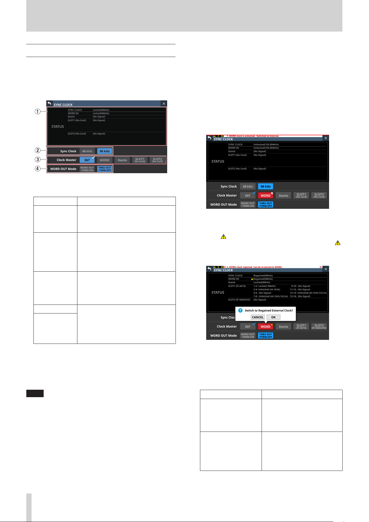
4 – Mixer configuration and settings
SYNC CLOCK screen
On this screen, the status of each audio clock is shown and
audio synchronization settings and word clock output jack
output mode settings can be made.
Tap Menu Screen > System Setup > Sync Clock to open this
screen.
1 STATUS display area
This shows the status of each audio clock.
Item Explanation
This shows the synchronization status of
SYNC CLOCK
WORD IN
Dante
SLOT1
SLOT2
2 Sync Clock buttons
These set the synchronization clock frequency of the digital
input and output signals.
The selected button will be highlighted light blue.
Options: 48 kHz, 96 kHz (default)
NOTE
i This unit will always operate internally at 96 kHz even when
synchronized to a master clock that is 48 kHz.
i Synchronization is possible even if the built-in Dante
“Sampling rate” and the main unit “Sync Clock” settings are
different. However, the IF-DA64 (Dante card) “Sampling rate”
and the main unit “Sync Clock” settings must be matched.
(Set the IF-DA64 (Dante card) “Sampling rate” with Dante
Controller.)
this unit with the master clock (Locked/
Unlocked/Regained) and the operation
frequency (96kHz/48kHz/No Signal).
This shows the synchronization status
of this unit with the WORD signal input
through the WORD IN jack (Locked/
Unlocked/Regained) and the operation
frequency (actual measured value/No
Signal).
This shows the synchronization status
of this unit with the connected Dante
system (Locked/Unlocked/Regained)
and the operation frequency (actual
measured value/No Signal).
These show the names of the expansion
cards in SLOT 1 and 2 and the
synchronization statuses of this unit
with them (Locked/Unlocked/Regained)
and the operation frequency (actual
measured value/No Signal).
3 Clock Master buttons
These set the master clock used by this unit for audio
synchronization. (default: INT)
o A 4 mark appears on the master clock being used.
o If the selected master clock is locked, the select button
will be highlighted light blue.
o If the selected external clock is unlocked, the unit will
operate using the internal clock. In this case the 4 will
be shown on the INT button as the clock in use, while ✖
is shown on the selected button for the unlocked source.
The selected button for the unlocked source will be
highlighted red.
o If synchronization becomes possible with an external
clock after synchronization with it failed (Regain state),
the 4 will be shown on the INT button as the clock in use,
while is shown on the selected button for the clock in
a regain state. Tap the red-highlighted button with the
mark to open a confirmation message for switching back
to the selected master clock.
Tap the OK button to switch to synchronization with the
selected external clock.
4 WORD OUT Mode buttons
These set the output mode of the WORD THRU/OUT
connector on the back of the unit.
The selected button will be highlighted light blue.
Option Meaning
This sets the signal output from
WORD OUT/TERM-ON
(default)
THRU OUT/TERM-OFF
the WORD/THRU OUT connector
to WORD OUT and turns WORD
IN connector termination
resistance (75Ω) on.
This sets the signal output from
the WORD/THRU OUT connector
to THRU output of the signal
from the WORD IN connector
and turns WORD IN connector
termination resistance (75Ω) off.
32 TASCAM Sonicview 16/Sonicview 24 V1.1.0

4 – Mixer configuration and settings
Setting the sampling frequency
1. Tap Menu Screen > System Setup > Sync Clock to open the
SYNC CLOCK Screen.
2. Tap the button for the desired sampling frequency to set it.
A confirmation message will appear.
3. Tap the OK button to switch the sampling frequency.
ATTENTION
Switching the sampling frequency will mute the sound for a
few seconds. Be aware of this timing when switching.
Setting the master clock
The unit's master clock can be set.
3. Tap the OK button to switch the master clock.
NOTE
i If the SLOT 1 or SLOT 2 button is tapped when an IF-AE16 or IF-
AN16/OUT is installed in SLOT 1 or SLOT 2, or if no expansion
card has been installed in that slot, the following message will
appear.
i If the selected external clock is unlocked, the unit will operate
using the internal clock. In this case the 4 will be shown on
the INT button as the clock in use, while ✖ is shown on the
selected button for the unlocked source. The selected button
for the unlocked source will be highlighted red.
ATTENTION
When connecting multiple digital audio devices, set up the
system so that it uses only one master clock.
1. Tap Menu Screen > System Setup > Sync Clock to open the
SYNC CLOCK Screen.
2. Tap the button for the desired master clock to set it.
A confirmation message will appear.
Button Use
INT The unit's internal clock is used.
WORD IN
Dante
SLOT1
SLOT2
Synchronize with the word clock signal
input through the WORD IN connector.
Synchronize with the clock of a connected
Dante system.
Synchronize with the digital signal clock
received through SLOT 1.
Synchronize with the digital signal clock
received through SLOT 2.
i When synchronization with the external master clock
becomes possible again, “WORD clock regained. Can be
re-synced to WORD.” will appear as a message at the top of
all touchscreens. Tap this message to open the SYNC CLOCK
Screen on the right touchscreen.
TASCAM Sonicview 16/Sonicview 24 V1.1.0 33

4 – Mixer configuration and settings
Tap the red-highlighted button with the mark to open
a confirmation message for switching back to the selected
master clock.
Tap the OK button to switch to synchronization with the
selected external clock.
ATTENTION
When switching the master clock, noise might occur in the
audio input and output.
Be aware of this when choosing when to change the master
clock.
PREFERENCES screen
Make settings and view information as follows on this screen.
o USB Keyboard type setting
o Snapshot STORE/RECALL confirmation setting
o Digital Reference Level setting
o Analog Reference Level setting
o Cooling fan operation mode and speed settings
o Cooling fan operation status display
o Temperature value and status display for various locations
o Brightness settings for the various displays
o Contrast settings for the channel screens
Tap any of the following menu screens to open this screen.
o “Brightness“ in the Front Panel Setup menu
o LAMP Dimmer Setup in the Rear Panel Setup menu
o Preferences in the System Setup menu
34 TASCAM Sonicview 16/Sonicview 24 V1.1.0
1 USB KEYBOARD TYPE buttons
Set the type of USB keyboard connected to the USB port on
the top of the unit.
The selected button will be highlighted.
Button Meaning
US US English keyboard
JPN (default) Japanese keyboard

4 – Mixer configuration and settings
2 Snapshot STORE Confirmation switch
Set whether or not to show a confirmation message when
storing snapshots.
When on, the sliding switch will appear highlighted.
NOTE
This can also be set by tapping the icon in the Snapshot
function item area at the top of the Menu Screen and
opening the CONFIRMATION settings window. (See
“Snapshot functions” on page 164.)
3 Snapshot RECALL Confirmation switch
Set whether or not to show a confirmation message when
recalling snapshots.
When on, the sliding switch will appear highlighted.
NOTE
This can also be set by tapping the icon in the Snapshot
function item area at the top of the Menu Screen and
opening the CONFIRMATION settings window. (See
“Snapshot functions” on page 164.)
4 CH Display Contrast GANG button
This turns the Channel Screen contrast adjustment knob
GANG function on or off (default).
When the GANG function is on, the button will appear
highlighted.
When the GANG function is on, operating any LCD knob 1–3
will cause the contrast settings of all to follow, maintaining
set differences.
5 CH Display Contrast knobs
Use these to adjust the contrasts of the channel screens.
Range: 0 – 60 (default: 40)
o Turn an LCD knob to adjust 1 step at a time.
o Press and turn an LCD knob to adjust 4 steps at a time.
LCD knob 1 Channels 1–8
LCD knob 2 Channels 9–16
LCD knob 3 Channels 17–24 (Sonicview 24 only)
NOTE
By turning an LCD knob while pressing the MENU key on
the top of the unit, the contrast of the channel screen that
corresponds to that knob can be adjusted. (See “12 – List of
shortcut operations” on page 206.)
6 Shortcut Help button
Tap this button to open a window that explains shortcut
operations for adjusting the contrast of channel screens and
brightness of the various displays.
7 LCD brightness knob
Turn LCD knob 5 (lit blue) to adjust the touchscreen
brightness.
Range: 0 – 7 (in steps of 1, default 6)
8 CH Display brightness knob
Turn LCD knob 6 (lit green) to adjust the channel screen
brightness.
Range: 0 – 7 (in steps of 1, default 6)
9 LED brightness knob
Turn LCD knob 7 (lit yellow) to adjust the indicator
brightness.
Range: 0 – 7 (in steps of 1, default 6)
0 LAMP brightness knob
Turn LCD knob 8 (lit red) to adjust the brightness of the lamp
connected to the LAMP connector on the rear panel.
Range: 0 – 7 (in steps of 1, default 6)
q Scroll bar display
This scroll bar shows the position of the setting items
currently shown on the screen relative to all items on the
PREFERENCES Screen.
NOTE
To view setting items not shown on the screen, swipe the
setting items area up and down to scroll the screen.
w Brightness GANG button
This turns the brightness knods GANG function on (default)
and off.
When the GANG function is on, the button will appear
highlighted.
When the GANG function is on, operating any LCD knob 5–8
will cause the brightness settings of all to follow, maintaining
set differences.
e Digital Reference Level buttons
Use these to set the digital reference level.
The selected button will be highlighted.
Options: -9dBFS, -14dBFS, -16dBFS, -18dBFS, -20dBFS
(default)
r Analog Reference Level buttons
Use these to set the analog reference level.
The selected button will be highlighted.
Options: +6dBu, +4dBu (default), 0dBu
NOTE
Depending on the Digital Reference Level button setting,
selection of some Analog Reference Level buttons will not be
possible.
Buttons that cannot be selected will appear dark gray.
Tap at the top right of the SHORTCUT HELP OPERATION
window or the Close Help button to close it.
Analog Reference Level
+6dBu +4dBu 0dBu
-9dBFS
Digital
Reference
Level
–: Selectable —: Not selectable
TASCAM Sonicview 16/Sonicview 24 V1.1.0 35
-14dBFS
-16dBFS
-18dBFS
-20dBFS
– — —
— – —
— – —
— – –
— – –
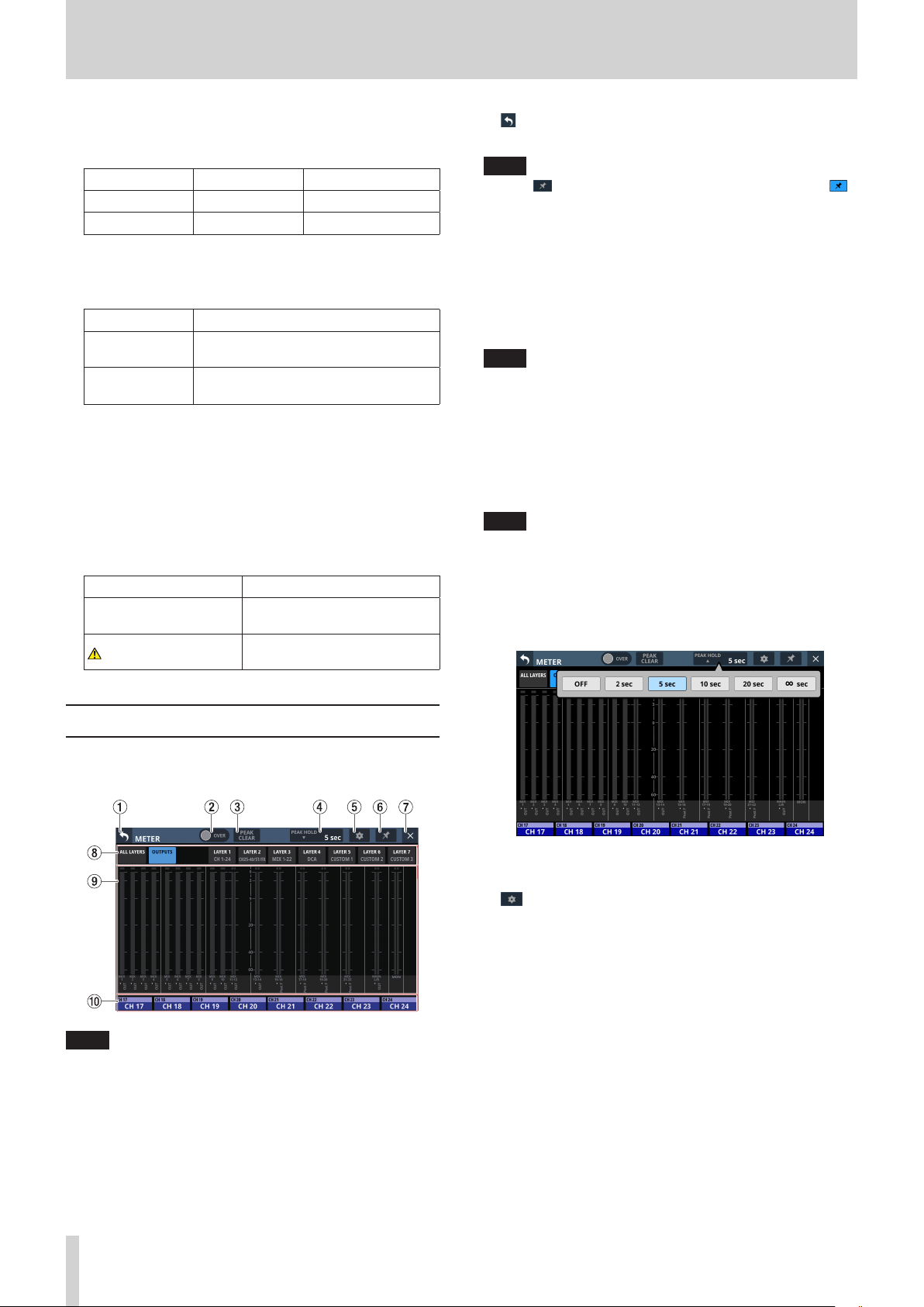
4 – Mixer configuration and settings
t FAN Status
This shows the cooling fan operation status and rotation
speed.
Indicator FAN STATUS Meaning
Green OK Normal
Red FAILURE Malfunctioning
y FAN Control buttons
Use these to set the internal cooling fan operation mode.
The selected button will be highlighted.
Button Meaning
Auto (default)
Manual
Cooling fan operation will be controlled
automatically.
FAN Speed (u) will be shown and the
user can set cooling fan operation.
u FAN Speed
When the operation mode of the cooling fan is “Manual”, its
rotation speed can be adjusted.
Range: 1.0 – 10.0 (36 levels, default: 3.5)
Turn LCD knob 4 (lit blue) to adjust it.
i Temperature Status
These show the temperature values of the SYSTEM (internal
temperature), CPU and DSP.
Indicator Meaning
Green
with orange WARNING
Temperature is within normal
range
Temperature is not in normal
range
1 button
Tap this button to return to the Menu Screen.
NOTE
If the button (6) on this screen appears highlighted ( ),
tapping this button will not return to the Menu Screen.
2 OVER Indic ator
o This will appear highlighted red if the signal level at a
metering point of any module has overloaded. This will
continue to appear highlighted for the PEAK HOLD time
(4) set on this screen.
o Tap this area to clear the highlighting of this indicator and
the overload indicators of all level meters.
NOTE
They will appear to light red when the level reaches or
exceeds -0.00026 dBFS (16-bit full-scale value).
3 PEAK CLEAR button
Tap this button to clear the peak hold indicators for the
following level meters.
o Peak indicators that are held below overload levels
o Overload indicators for all level meters
NOTE
The OVER indicator (2) on this screen will not be cleared.
4 PEAK HOLD time display
o This shows the level meter peak hold time.
o Tap this area to open a window where the level meter
peak hold time can be set.
METER screen
View various meters and make settings for them on this screen.
Tap Menu Screen > Mixer Setup > Meter to open this screen.
NOTE
Using the User Defined Control function, this screen can also
be opened with a USER KEY, footswitch or the GPIO-IN. (See
“USER DEFINED CONTROLS screen” on page 42.)
Options: OFF(no hold), 2 sec, 5 sec (default), 10 sec, 20 sec,
∞ sec (hold until cleared)
5 button
Tap this button to open the METER SETUP Screen. (See
“METER SETUP screen” on page 38.)
36 TASCAM Sonicview 16/Sonicview 24 V1.1.0

4 – Mixer configuration and settings
6 button
o Tap this button, highlighting it, to disable the METER
Screen (1) and (7) buttons as shown below and
prevent the METER Screen from being closed.
In this state, the METER Screen will stay open even if the
HOME button on the top of the unit is pressed.
The screen can still be switched, however, by conducting
the following operation.
i Tap the (5) button to open the METER SETUP
Screen.
i Press the MENU key on the top panel to switch to the
Menu Screen.
i Press the HOME and MENU keys together to open the
LOCK SETUP Screen.
i Press the SEL key on the top panel to switch to the
MODULE Screen.
i Tap the Home Screen NAME area (0) at the bottom of
this screen to open the MODULE (OVERVIEW) Screen.
o Tap the button when it is highlighted ( ) to open a
confirmation message.
9 Meter Area
o The level meters are shown for the page with the
highlighted selection button.
Page name Contents
This shows level meters for the
modules assigned to all of the 7 layers
ALL LAYERS
OUTPUTS
LAYER1
LAYER2
LAYER3
LAYER4
LAYER5
LAYER6
LAYER7
o Two meters will be shown for stereo modules.
o Each level meter has an overload indicator at its top. They
will appear to light red when the signal level reaches or
exceeds -0.00026 dBFS (16-bit full-scale value).
o When a level overload occurs, the entire bar meter will
light red.
o The area below -60 dBFS at the bottom of the level meters
will light when above -70 dBFS.
on one line per layer.
User module names (names set by
user) are shown at the bottom of the
level meters.
This shows level meters for MIX 1–22
and MAIN L/R Master modules and
the MONITOR OUT.
The module names, user module
names and metering points are
shown below the level meters.
This shows level meters for
the modules assigned to the
corresponding layer.
The module names, user module
names and metering point names are
shown below the level meters.
0 Home screen name area
o This shows the same information as the NAME area on
the Home Screen for modules assigned to the right
touchscreen on the current layer (module name, user
module name, Mute Group assignment).
o Tap this area to open the MODULE (OVERVIEW) Screen.
(See “MODULE (OVERVIEW) Screen” on page 112.)
Tap the OK button to end highlighting of the button,
enabling closing of the METER Screen.
7 button
Tap this button to return to the Home Screen.
NOTE
If the button (6) on this screen appears highlighted ( ),
tapping this button will not return to the Home Screen.
8 Page selection buttons
o The button for the currently selected page is highlighted
and corresponding level meters are shown in the meter
area (9).
o Tap one of these buttons to switch to showing the
corresponding level meters.
TASCAM Sonicview 16/Sonicview 24 V1.1.0 37

4 – Mixer configuration and settings
METER SETUP screen
Make the following settings on this screen.
o METERING POINT page
Set the metering points for each module type.
o METER HEADROOM page
Set the point where level meter colors change on each
screen.
Tap on the METER Screen to open this screen.
1 OVER Indic ator
This has the same function as the OVER indicator on the
METER Screen. (See “METER screen” on page 36.)
2 PEAK CLEAR button
This has the same function as the PEAK CLEAR button on the
METER Screen. (See “METER screen” on page 36.)
3 PEAK HOLD time display
This has the same function as the PEAK HOLD time display on
the METER Screen. (See “METER screen” on page 36.)
4 button
Tap this button to return to the METER Screen. (See “METER
screen” on page 36.)
5 Page selection buttons
Tap these buttons to switch the page shown.
6 Home screen name area
This shows the NAME area of the right touchscreen Home
Screen. (See “METER screen” on page 36.)
Module type default
CH 1–40 module PRE HPF
ST IN 1–2 module PRE EQ
FX RTN 1–4 module FX OUTPUT
MIX 1–22 and MAIN L/R Master modules
when the BUS mode is AUX
MIX 1–22 modules when the BUS mode is
GROUP
* Metering Point “OUTPUT” setting explanation
For the following module types, this is the Metering Point
setting when the icon to the right of “OUT PORT STATUS” is
lit ( ).
i MIX: AUX MODE, MAIN L/R
i MIX: GROUP MODE
NOTE
i These can also be set on the MODULE (OVERVIEW) screens
for each module using Metering Point buttons. (See
“MODULE (OVERVIEW) Screen” on page 112.)
i When the Metering Point is OUTPUT*, and the corresponding
bus has not been assigned to an output port (not being
output from the unit), meters will not be shown.
OUTPUT*
POST FADER
METER HEADROOM page
On this page, set the point where level meter colors change on
each screen.
Options: -9dBFS, -14dBFS, -16dBFS, -18dBFS, -20dBFS, Ref.
Level (default)
METERING POINT page
Set the metering points for each module type on this page.
Tap icons to set metering points.
When a metering point is selected, that icon will appear
highlighted ( ).
38 TASCAM Sonicview 16/Sonicview 24 V1.1.0
Swipe the options up and down to select the point where colors
change.
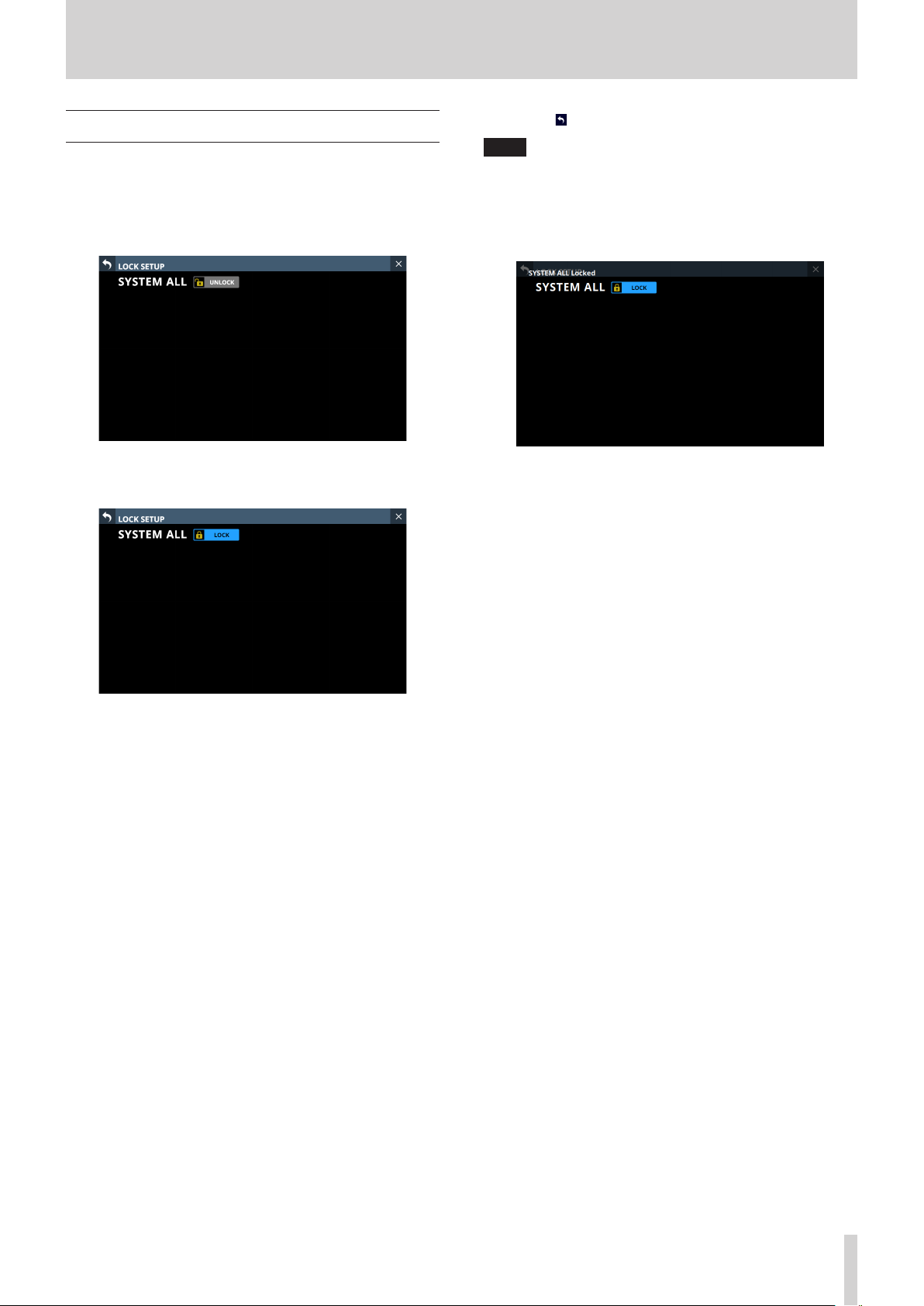
4 – Mixer configuration and settings
LOCK SETUP screen
On this screen, set the lock function to prevent this unit from
being controlled from its front panel or an external device.
1. Press and hold the HOME and MENU keys on the top panel
together for 5 seconds to open the LOCK SETUP Screen on
the right touchscreen.
2. Tap this button to lock and unlock.
The button will be highlighted when set to “LOCK”.
3. Tap the button to return to the Home Screen.
NOTE
i When SYSTEM ALL is set to “LOCK”, operation from all locked
items will be prohibited.
i Attempts to operate or control when set to “LOCK” will cause
a message to appear on all touchscreens for about two
seconds.
Lockable controls and operations
i LCD touchscreen operations (except the LOCK SETUP
Screen)
i LCD knob operations
i Fader operations
i Top panel key operations (except pressing HOME and
MENU keys simultaneously)
i Operations from a network
i Footswitch operations
i GPIO-IN operations
i The following controls and operations will not be locked.
i Headphone volume
i MONITOR OUT volume
i TALKBACK volume
i POWER switch
i Pressing HOME and MENU keys simultaneously
i Touchscreen operations on the LOCK SETUP Screen
TASCAM Sonicview 16/Sonicview 24 V1.1.0 39

4 – Mixer configuration and settings
MIXER CONFIG screen
Make the following settings on this screen.
o CH 1–40 CONFIG page
i CH 1–40 stereo link settings
i DIRECT OUT POINT settings
i DELAY POINT settings
i INSERT POINT unified settings
o BUS CONFIG page
i BUS MODE settings
i MIX 1–22 stereo link settings
i Pan link settings
Tap Menu Screen > Mixer Setup > Mixer Config/Bus Config to
open this screen.
CH 1–40 CONFIG page
1 Page selection buttons
Tap these buttons to switch the page shown.
2 CH 1–40 module name button area
o This shows the module names and user module names for
the CH 1–40 modules.
o Tap these buttons to open the MODULE NAME Screen
where the user module name and set module color can be
changed. (See “MODULE NAME screen” on page 160.)
3 STEREO LINK button area
o These show the stereo link settings states of the CH 1–40
modules.
o Tap these buttons to turn the stereo link setting on and off
(default) for the CH 1–40 modules.
When the stereo link is on, the button will appear
highlighted.
4 Scroll knob and scrollbar
Drag the scrollbar left and right to show CH 1–40 modules
that are not shown on the screen. The screen can also be
scrolled by turning LCD knob 8.
NOTE
The screen can also be scrolled by swiping left and right
between the CH 1–40 module NAME area (2) and the
STEREO LINK button area (3).
5 DIRECT OUT POINT buttons
Tap these buttons to change all direct out points for the CH
1–40 modules at the same time.
Options: INPUT (default), POST HPF, POST FADER
6 DELAY POINT buttons
Tap these buttons to change the delay function insert
position for the CH 1–40 modules at the same time.
7 INSERT POINT BATCH SETUP buttons
These change all the insert points at once for the CH 1–40
modules, which can be set individually on the MODULE
(OVERVIEW) Screen.
Tapping a button will open a setting change confirmation
message.
Tap the OK button to change the insert points for all CH 1–40
modules at the same time.
40 TASCAM Sonicview 16/Sonicview 24 V1.1.0
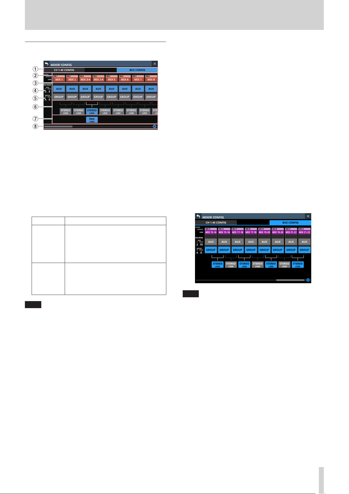
4 – Mixer configuration and settings
BUS CONFIG page
1 Page selection buttons
Tap these buttons to switch the page shown.
2 MIX 1–22 MODULE NAME area
o This shows the module names and user module names for
the MIX1–22 modules.
o Tap these buttons to open the MODULE NAME Screen
where the user module name and set module color can be
changed. (See “MODULE NAME screen” on page 160.)
3 BUS MODE area
Tap these buttons to change the bus modes of MIX 1–22
modules.
5 GROUP bus counts
This shows the number of modules set to GROUP in the BUS
MODE area.
o “ST” shows the number of GROUP mode module pairs that
have the stereo link setting on.
o “MONO” shows the number of GROUP mode modules that
have the stereo link setting off.
6 STEREO LINK button area
o These show the stereo link settings states of the MIX1–22
modules.
o Tap these buttons to turn the stereo link setting on/off for
the MIX 1–22 modules.
When the stereo link is on, the button will appear
highlighted.
7 PAN LINK button area
These buttons appear when MIX 1–22 module stereo link
settings are on and the BUS mode is AUX.
When the PAN LINK setting is on, the AUX bus pan/balance
(SEND PAN) setting is linked to the MAIN L/R bus pan/balance
setting.
8 Scroll knob and scrollbar
Drag the scrollbar left and right to show MIX1–22 modules
that are not shown on the screen. The screen can also be
scrolled by turning LCD knob 8.
Button Function
Set the MIX bus that corresponds to the
button to function as an AUX bus.
AUX
GROUP
NOTE
i When BUS is changed from GROUP to AUX, the setting color
of corresponding MIX 1–22 modules will change to orange.
i When BUS is changed from AUX to GROUP, the setting color
of corresponding MIX 1–22 modules will change to purple.
SEND level, on/off and PRE/POST settings
can be made from each module to AUX
mode buses. (PRE/POST is only for input
modules.)
Set the MIX bus that corresponds to the
button to function as a GROUP bus.
Only on/off can be set for modules to
GROUP mode buses. They are always sent
POST FADER.
4 AUX bus counts
This shows the number of modules set to AUX in the BUS
MODE area.
o “ST” shows the number of AUX mode module pairs that
have the stereo link setting on.
o “MONO” shows the number of AUX mode modules that
have the stereo link setting off.
NOTE
The screen can also be scrolled by swiping left and right
between the MIX1-22 module NAME area (2) and the PAN
LINK button area (7).
TASCAM Sonicview 16/Sonicview 24 V1.1.0 41
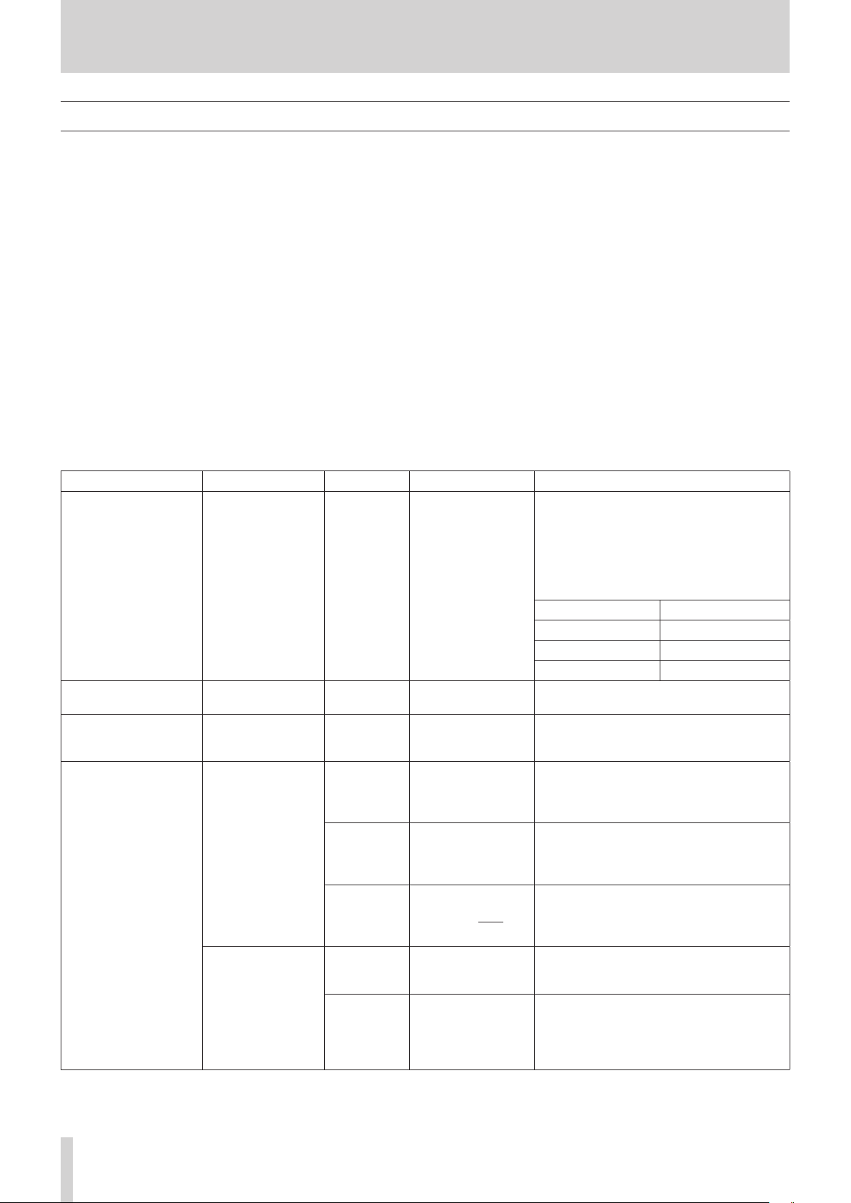
4 – Mixer configuration and settings
USER DEFINED CONTROLS screen
The following settings can be made on this screen.
o User Key page
Functions can be assigned to USER KEY A–F and USER KEY 1–12.
Tap Menu Screen > Front Panel Setup > User Key Setup to open this page.
o Foot Switch page
Functions can be assigned to the footswitch.
Tap Menu Screen > Rear Panel Setup > FOOT SW Setup to open this page.
o GPIO-IN page
Functions can be assigned to the GPIO input connector of this unit or of an SB-16D connected through the built-in Dante.
Tap Menu Screen > Rear Panel Setup > GPIO Input Setup to open this page.
o GPIO-OUT page
Functions can be assigned to the GPIO output pins of an SB-16D connected to this unit or through the built-in Dante.
Tap Menu Screen > Rear Panel Setup > GPIO Output Setup to open this page.
The settings for keys and connectors are made in operation setting tables on each page.
Tap one of the four page selection buttons to open that page. (See “USER DEFINED CONTROLS screen structure” on page 46.)
The functions that can be assigned on these pages are as follows.
User Key, Foot Switch and GPIO-IN pages
Function Parameter1 Parameter2 Parameter3 Function explanation
Use to tap the tempo to input the DELAY TIME
when the selected effect type is DELAY. (See
“MODULE (FX) Screen” on page 128.)
When the effect type is any delay other than
“DELAY LCR”, set Parameter 2 to “Delay 1”.
Tap Tempo FX1–4 Delay1–3
Mute Group 1–8
Sends On Fader Mix1–22/FX1–4
Next
Select
Snapshot
Recall
Prev
No 1-128/P001-Pxxx
Selected
Next
When the effect type is “DELAY LCR”, set
Parameter 2 as follows.
Desired parameter Parameter 2 setting
DELAY TIME L Delay1
DELAY TIME C Delay2
DELAY TIME R Delay3
Turn the selected Mute Group on/off. (See
“Mute Group Master page” on page 160.)
Turn the Sends On Fader mode for the
selected bus on/off. (See “SENDS ON FADER
screen” on page 148.)
Increase by one the number of the Snapshot
available for STORE/RECALL shown at the top
of the Menu Screen. (See “Snapshot functions”
on page 164.)
Decrease by one the number of the Snapshot
available for STORE/RECALL shown at the top
of the Menu Screen. (See “Snapshot functions”
on page 164.)
This makes the specified Snapshot number
shown at the top of the Menu Screen the
target for STORE/RECALL. (See “Snapshot
functions” on page 164.)
Recall the Snapshot available for RECALL
shown at the top of the Menu Screen. (See
“Snapshot functions” on page 164.)
Switch the number of the Snapshot available
for RECALL shown at the top of the Menu
Screen to the Snapshot that is one later, and
then recall it. (See “Snapshot functions” on
page 164.)
42 TASCAM Sonicview 16/Sonicview 24 V1.1.0

4 – Mixer configuration and settings
Function Parameter1 Parameter2 Parameter3 Function explanation
Switch the number of the Snapshot available
for RECALL shown at the top of the Menu
Snapshot
Screen
Prev
Recall
Store
Target
Undo/Redo Undo Color Redo Color
TALKBACK/
OSCILLATOR
METER
RECORDER/PLAYER
No 1-128/P001-Pxxx
+Target Key
Selected
No 1-128
+Target Key
Selected
Next
Prev
No 1-128/P001-Pxxx
ALL LAYER
OUTPUT
LAYER1–7
LAST TAB
Screen to the Snapshot that is one earlier, and
then recall it. (See “Snapshot functions” on
page 164.)
Recall a snapshot by number. (See “Snapshot
functions” on page 164.)
Press this simultaneously with a key that has
Function set to Snapshot and Parameter 1 set
to Target to recall that set snapshot number.
(See “Snapshot functions” on page 164.)
Store the Snapshot available for STORE shown
at the top of the Menu Screen. (See “Snapshot
functions” on page 164.)
Store a snapshot by number. (See “Snapshot
functions” on page 164.)
Press this simultaneously with a key that has
Function set to Snapshot and Parameter 1 set
to Target to store in that set snapshot number.
(See “Snapshot functions” on page 164.)
However, even when Function is set to
Snapshot and Parameter 1 is set to Target, this
will not work if the key assigned to Parameter
2 as “Next” or “Prev” is pressed at the same
time.
Press simultaneously with a key assigned to a
+Target Key function to STORE to or RECALL
from the Snapshot number shown at the top
of the Menu Screen.
Press simultaneously with a key assigned to
a +Target Key function to make the Snapshot
number target for STORE/RECALL one after
that shown at the top of the MENU Screen
subject to RECALL.
Press simultaneously with a key assigned to
a +Target Key function to make the Snapshot
number target for STORE/RECALL one before
that shown at the top of the MENU Screen
subject to RECALL.
Press simultaneously with a key assigned to a
+Target Key function to STORE to or RECALL
from the specified Snapshot number.
Undo/redo Snapshot RECALL operations. (See
“Snapshot functions” on page 164.)
When undoing is possible, the USER KEY that
this function is assigned to will light in the
color set by Parameter 2: Undo Color. When
redoing is possible, the USER KEY that this
function is assigned to will light in the color
set by Parameter 3: Redo Color. (Parameters 2
and 3 can only be set to USER KEY.)
Show the TALKBACK/OSCILLATOR page of
the MONITOR SETUP Screen on the rightmost
touchscreen and light the corresponding
USER KEY. When this screen is open, pressing
a corresponding USER KEY will close it.
Show the page of the METER Screen specified
by Parameter 2 on the rightmost touchscreen
and light the corresponding USER KEY. When
this screen is open, pressing a corresponding
USER KEY will close it.
Show the RECORDER PLAYER Screen on the
right touchscreen and light the corresponding
USER KEY. When this screen is open, pressing
the corresponding USER KEY will close it.
TASCAM Sonicview 16/Sonicview 24 V1.1.0 43

4 – Mixer configuration and settings
Function Parameter1 Parameter2 Parameter3 Function explanation
Turn the talkback mic on/off. (See “Making
Talkback ON/OFF
Monitor Source Select Monitor Select 1–6
MUTE
Monitor Control
DIM
CH 1–40
ST IN 1–2
SEND ON/OFF
NOTE
i Foot Switch: GPIO-IN:
i Whe n Mute Group, Talkback, Monitor Control and SEND ON/OFF functions are assigned, the selected function will be activated
while a Low level signal is being input. Moreover, if the same function is assigned to multiple GPIO-IN and/or footswitches, the
function will be activated when any one of those signals is Low level. The function will be deactivated only when all the signals
from the assigned GPIO-IN and/or footswitches are High level (OR operation).
i When other functions are assigned, the selected function will operate if a Low level signal of 50 ms or longer is input.
i Snapshots stored with this function are named “USER KEY” followed by a three-digit slot number (for example, “USER KEY 018”).
i When the Function is set to Snapshot and Parameter 2 is set to No, if Parameter 3 matches the current Snapshot number, the
corresponding USER KEY will light.
FX RTN 1–4
MIX 1–22
MAIN L/R
MIX 1–22
FX 1–4
talkback and built-in oscillator settings” on
page 57.) (See “j TALKBACK key and
indicator” on page 10.)
Select a specific number for Monitor Select.
(See “1 MONITOR SELECT buttons” on page
54.)
Turn monitoring signal muting on/off. (See “4
Monitor MUTE button” on page 54.)
Turn monitoring signal dimming on/off. (See
“5 Monitor DIM button” on page 54.)
This turns ON/OFF the SEND from the
module specified with Parameter 1 to the bus
specified with Parameter 2.
The key will light when this setting is on.
44 TASCAM Sonicview 16/Sonicview 24 V1.1.0
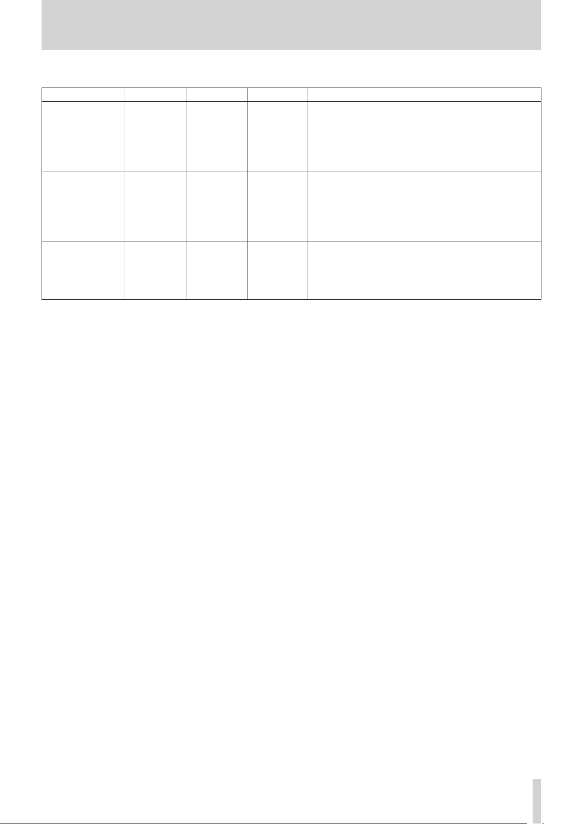
4 – Mixer configuration and settings
GPIO-OUT page
Function Parameter1 Parameter2 Parameter3 Function explanation
A pulse signal will be output when the status of the specified
module becomes as follows (Active Low/150ms pulse width).
o When MUTE is off and the FADER level changes from below
to above the fader start level setting value
o When the FADER level is above the fader start level setting
value, and MUTE changes from on to off
A pulse signal will be output when the status of the specified
module becomes as follows (Active Low/150ms pulse width).
o When MUTE is off, and the FADER level changes from
above to below the fader start level setting value
o When the FADER level is above the fader start level setting
value and MUTE changes from off to on
When MUTE is off for the specified module and the FADER
level is above the fader start level setting value, LOW level
signal output will be latched.
Fader Start
Fader Stop
Fader Start/Stop
CH 1–40
ST IN 1–2
FX RTN 1–4
MIX 1–22
MAIN L/R
CH 1–40
ST IN 1–2
FX RTN 1–4
MIX 1–22
MAIN L/R
CH 1–40
ST IN 1–2
FX RTN 1–4
MIX 1–22
MAIN L/R
TASCAM Sonicview 16/Sonicview 24 V1.1.0 45
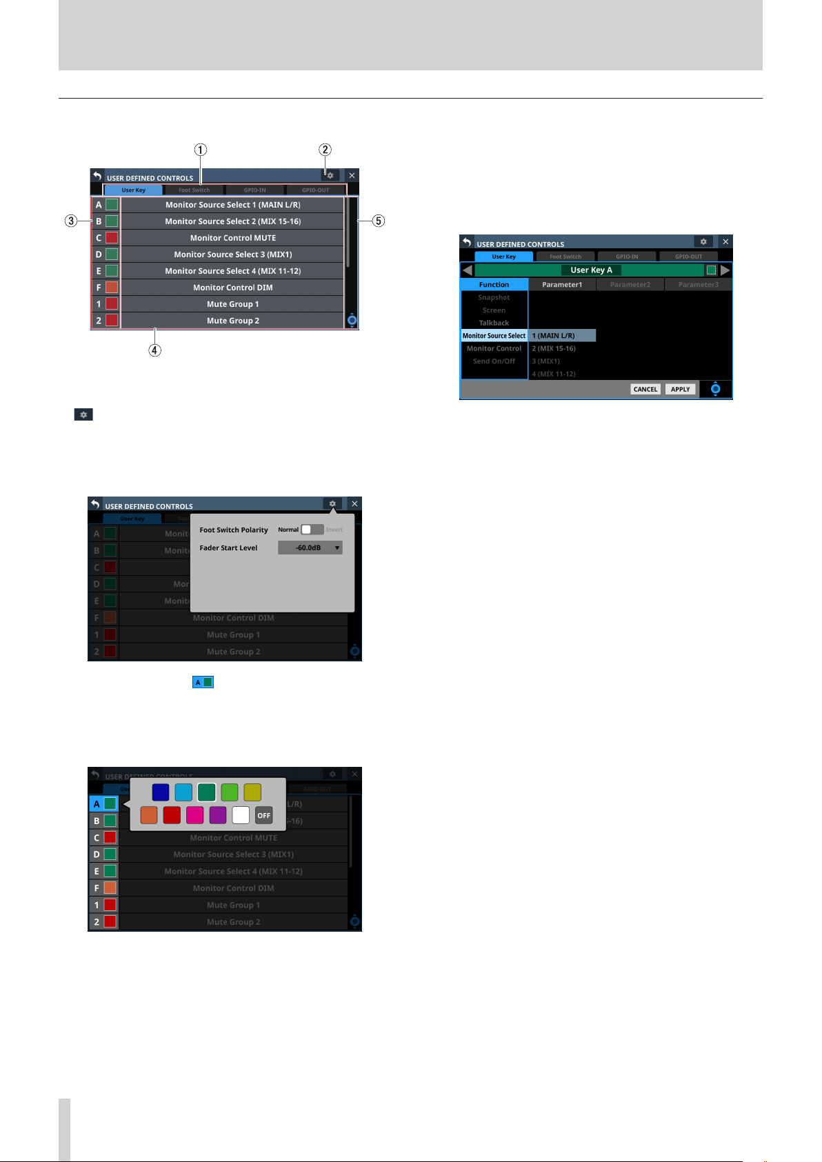
4 – Mixer configuration and settings
USER DEFINED CONTROLS screen structure
4 Set function names
1 Page selection buttons
Tap these buttons to switch the page shown.
2 button
Tap this button to open a window where the footswitch
polarity and fader start level can be set. (See “Setting the
footswitch polarity” on page 48.) (See “Fader Start Level
setting” on page 49.)
5 Scroll knob and scrollbar
These appear when all selectable options cannot be shown
on the display at the same time.
Drag the bar to scroll the visible options. The options can also
be scrolled by swiping up and down on the control name
(3) and set function name (4) area as well as by turning LCD
knob 8.
o The show the names of functions that have been assigned
to the controls.
o Tap this area to open the control setting table for the
controls.
3 Control names and buttons (User Key page
only)
The colors that USER KEY light when their functions are
activated can be set.
Tap these buttons to open a color palette window.
Tap a color in the color palette to close the window and
change the control name display color.
46 TASCAM Sonicview 16/Sonicview 24 V1.1.0
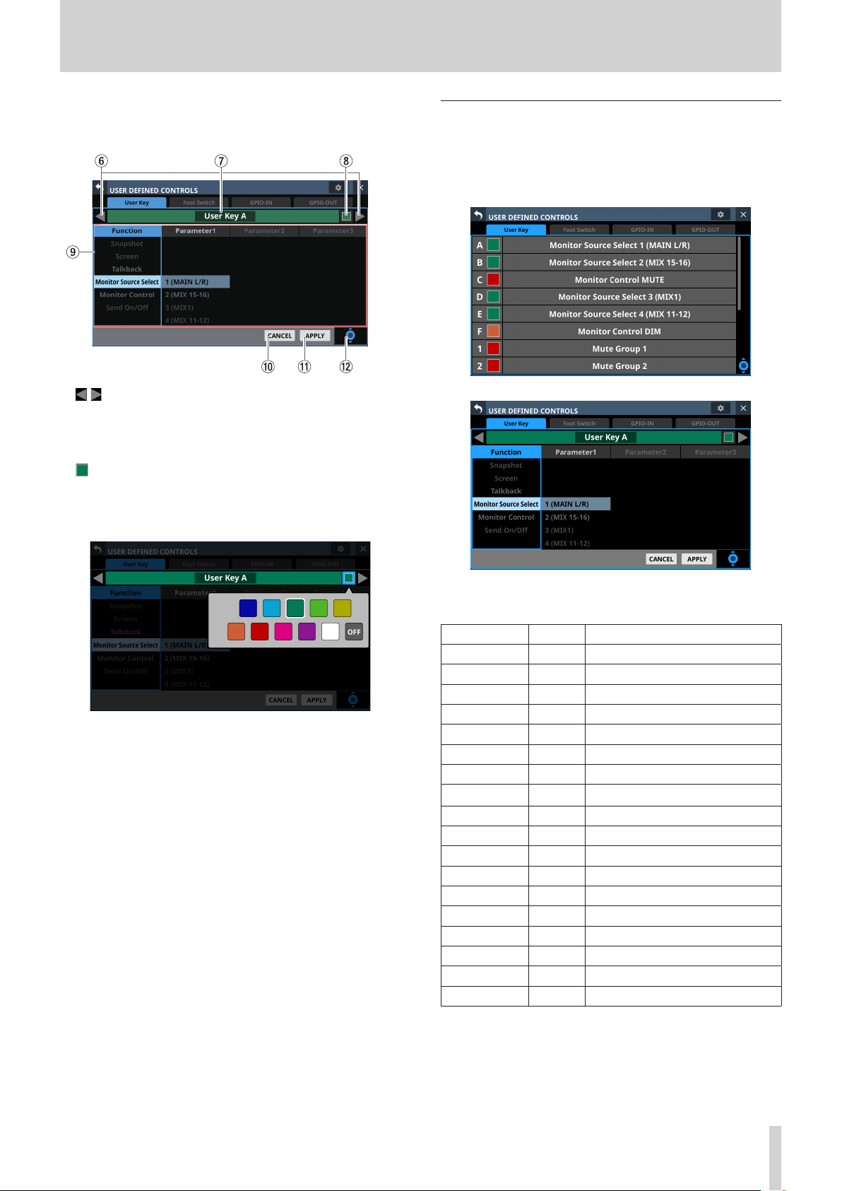
4 – Mixer configuration and settings
Control setting on USER DEFINED CONTROLS
Screen
6 / buttons
Tap these buttons to switch the control that is being edited.
7 Control name area
This shows the name of the currently selected control.
8 button (USER Key page only)
The colors that USER KEY light when their functions are
activated can be set.
Tap these buttons to open a color palette window.
User Key page
On this page, functions can be assigned to USER KEY A–F and
USER KEY 1–12.
Tap Menu Screen > Front Panel Setup > User Key Setup to open
this page.
Tap a color in the color palette to close the window and
change the control name display color.
9 Function list
o Functions that can be set for the controls and their
parameters are shown in a 4-column list.
o Tap a column and select the setting to be changed. The
selected column will be highlighted.
o To change a setting, swipe the list up and down in the
highlighted column. The setting can also be changed by
turning LCD knob 8 (lit light blue).
0 CANCEL button
Tap this button to cancel setting changes and return to the
top USER DEFINED CONTROLS Screen.
q APPLY button
Tap this button to apply setting changes and return to the
top USER DEFINED CONTROLS Screen.
w Scroll knob icon
This icon shows that LCD knob 8 (lit light blue) can be used
to scroll.
User Key page when setting controls
The factory default settings are as follows.
Key Lit color Assigned function
USER KEY A Green Monitor Source Select 1 (MAIN L/R)
USER KEY B Green Monitor Source Select 2 (MIX15–16)
USER KEY C Red Monitor MUTE
USER KEY D Green Monitor Source Select 3 (MIX1)
USER KEY E Green Monitor Source Select 4 (MIX11–12)
USER KEY F Orange Monitor DIM
USER KEY 1 Red Mute Group 1
USER KEY 2 Red Mute Group 2
USER KEY 3 Red Mute Group 3
USER KEY 4 Red Mute Group 4
USER KEY 5 Orange Sends On Fader Mix1
USER KEY 6 Orange Sends On Fader Mix2
USER KEY 7 Orange Sends On Fader Mix3
USER KEY 8 Orange Sends On Fader Mix4
USER KEY 9 Orange Sends On Fader Mix5
USER KEY 10 Orange Sends On Fader Mix6
USER KEY 11 Orange Sends On Fader Mix7
USER KEY 12 Orange Sends On Fader Mix8
TASCAM Sonicview 16/Sonicview 24 V1.1.0 47

4 – Mixer configuration and settings
Foot Switch page
Functions can be assigned to the footswitch on this page.
Tap Menu Screen > Rear Panel Setup > FOOT SW Setup to open
this page.
GPIO-IN page
On this page, functions can be assigned to the GPIO input
connector of this unit or of a mounted SB-16D connected
through the built-in Dante.
See “Using GPIO extension functions” on page 79 for details
about using the GPIO connector of a mounted SB-16D.
Tap Menu Screen > Rear Panel Setup > GPIO Input Setup to
open this page.
Foot Switch page when setting controls
The factory default setting is “Tap Tempo FX3 Delay1”.
Setting the footswitch polarity
This unit was designed to be used with momentary footswitches
that must be pushed to function (shorted when pushed). Since
the polarity can be reversed, however, push-to-break (shorted
with not pushed) footswitches can also be used.
The setting of this unit can be changed according to the polarity
of the footswitch being used.
1. Tap the button on the USER DEFINED CONTROLS Screen
to open a settings window.
GPIO-IN page when setting controls
The factory default settings are as follows.
Port number Assigned function
1 Mute Group 1
2 Mute Group 2
3 Mute Group 3
4 Mute Group 4
5 Mute Group 5
6 Talkback ON/OFF
7 Tap Tempo FX3 Delay1
8 Tap Tempo FX4 Delay1
NOTE
The GPIO input connector of a mounted SB-16D does not
have functions assigned when shipped from the factory.
2. Tap the Foot Switch Polarity slider in the window to set the
footswitch polarity.
Options: Normal (default), Invert
48 TASCAM Sonicview 16/Sonicview 24 V1.1.0

4 – Mixer configuration and settings
GPIO-OUT page
On this page, functions can be assigned to the GPIO output
connector of this unit or of a mounted SB-16D connected
through the built-in Dante.
See “Using GPIO extension functions” on page 79 for details
about using the GPIO connector of a mounted SB-16D.
Tap Menu Screen > Rear Panel Setup > GPIO Output Setup to
open this page.
2. Tap the setting level value of the Fader Start Level item in
the window to change its appearance as shown below. The
Channel Screens also switch to showing fader start setting.
GPIO-OUT page when setting controls
The factory default settings are as follows.
Port number Assigned function
1 Fader Start/Stop CH29
2 Fader Start/Stop CH31
3 Fader Start/Stop CH33
4 Fader Start/Stop CH35
5 Fader Start/Stop CH37
6 Fader Start/Stop CH39
7 Fader Start/Stop STIN1
8 Fader Start/Stop STIN2
NOTE
The GPIO output connector of a mounted SB-16D does not
have functions assigned when shipped from the factory.
3. Adjust the channel faders on the right top panel to the
desired start/stop trigger levels.
The adjusted values are shown in the window.
4. Tap the APPLY button to set the fader start level to the
position of the corresponding fader, closing the window
and returning to normal display.
Fader Start Level setting
This sets the trigger level of the fader start/stop function
(default: -60 dB).
1. Tap the button on the USER DEFINED CONTROLS Screen
to open a settings window.
Tap the CANCEL button to close the window and return to
normal display.
TASCAM Sonicview 16/Sonicview 24 V1.1.0 49
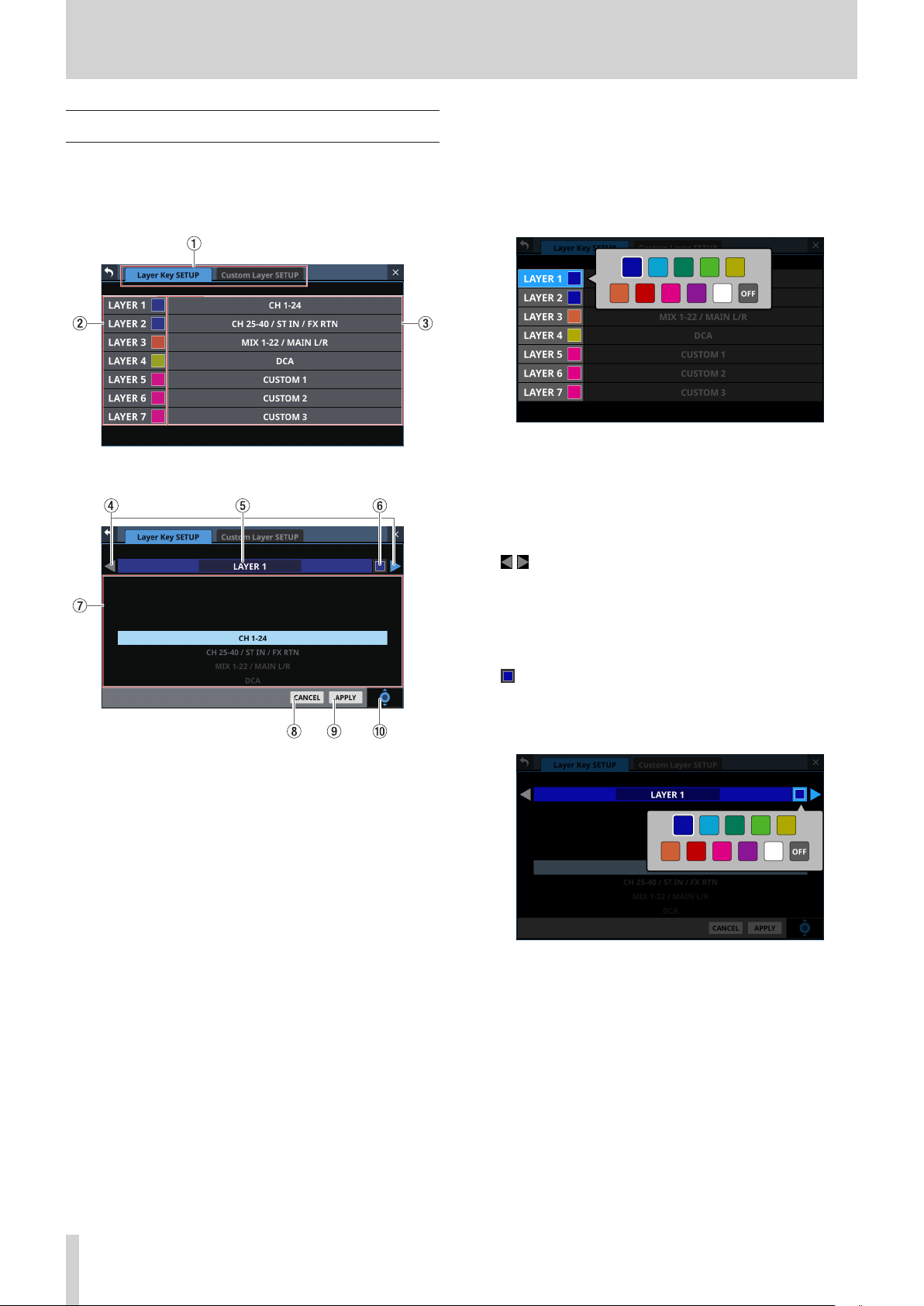
4 – Mixer configuration and settings
Layer Key SETUP page
Assign channel sets and custom layers to the 7 LAYER KEYS on
this screen.
Tap Menu Screen > Front Panel Setup > Layer/Master Fader
Setup to open this page.
Sonicview 24 Layer Key SETUP Screen
1 Page selection buttons
Tap these buttons to switch the page shown.
2 Layer Key names
The colors that LAYER KEY 1–7 light when they are selected
can be set.
Tap this area to open a color palette window.
Tap a color in the color palette to change the layer key name
button color and close the palette window.
3 Layer Key settings
o This shows channel sets and custom layers assigned to
LAYER KEY 1–7.
o Tap this area to open a settings screen for the layer keys.
4 / buttons
Tap these buttons to switch the LAYER KEY (1–7) that is being
edited.
5 Layer Key name
This shows the name of the currently selected LAYER KEY
(1–7).
6 button
The colors that LAYER KEY 1–7 light when they are selected
can be set.
Tap this button to open a color palette window.
Layer Key SETUP layer key setting screen
Tap a color in the color palette to change the layer key name
display color and close the palette window.
50 TASCAM Sonicview 16/Sonicview 24 V1.1.0

4 – Mixer configuration and settings
7 Settings list
o This shows channel sets and custom layers that can be set
for LAYER KEY 1–7.
o To change a setting, swipe the list up and down. The
setting can also be changed by turning LCD knob 8 (lit
blue).
o Settings that can be selected are as follows.
Model Option
CH 1–16
CH 17–32
CH 33–40 / ST IN / FX RTN
MIX 1–16
MIX 17–22 / MAIN L/R
DCA
Sonicview 16
Sonicview 24
CUSTOM 1
CUSTOM 2
CUSTOM 3
CUSTOM 4
CUSTOM 5
CUSTOM 6
CUSTOM 7
CH 1–24
CH 25–40 / ST IN / FX RTN
MIX 1–22 / MAIN L/R
DCA
CUSTOM 1
CUSTOM 2
CUSTOM 3
CUSTOM 4
CUSTOM 5
CUSTOM 6
CUSTOM 7
Default settings for LAYER KEY 1–7
The factory default settings are as follows.
Sonicview 16
Key Lit color Assigned function
LAYER 1 Blue CH 1–16
LAYER 2 Blue CH 17–32
LAYER 3 Blue CH 33–40 / ST IN / FX RTN
LAYER 4 Orange MIX 1–16
LAYER 5 Orange MIX 17–22 / MAIN L/R
LAYER 6 Yellow DCA
LAYER 7 Pink CUSTOM 2
Sonicview 24
Key Lit color Assigned function
LAYER 1 Blue CH 1–24
LAYER 2 Blue CH 25–40 / ST IN / FX RTN
LAYER 3 Orange MIX 1–22 / MAIN L/R
LAYER 4 Yellow DCA
LAYER 5 Pink CUSTOM 1
LAYER 6 Pink CUSTOM 2
LAYER 7 Pink CUSTOM 3
Custom Layer SETUP page
The modules assigned to custom layers and the modules
assigned to the master fader can be set in the settings list on
this screen.
Tap Menu Screen > Front Panel Setup > Layer/Master Fader
Setup to open the Layer Key Setup page. Then, tap the Custom
Layer Setup button to open this page.
8 CANCEL button
Tap this button to cancel setting changes and close to the
layer settings screen.
9 APPLY button
Tap this button to confirm setting changes and close to the
layer settings screen.
0 Scroll knob icon
This icon shows that LCD knob 8 (lit light blue) can be used
to scroll.
1 Page selection buttons
Tap these buttons to switch the page shown.
TASCAM Sonicview 16/Sonicview 24 V1.1.0 51

4 – Mixer configuration and settings
2 Custom Layer selection
o This shows the name of the custom layer that is being
edited.
o Tap this area to open a window where the custom layer
can be selected.
Tap the name of the custom layer to be edited to close this
window and show the names of the modules assigned to
the layer in the custom layer slot buttons (5).
o Tap “All Custom Layers” in the window to close the
window and open the All Custom Layers display.
This shows the names of the modules assigned to all 7
custom layers on one line per layer.
Tap a button shown to switch to display of its custom
layer.
3 Module group switching buttons
Tap these buttons to change which group of modules
assigned to the layer is shown.
Use the block selection buttons (7) to switch the 8 channels
that are shown.
6 button
Tap this button to open the custom layer editing menu.
Items that can be used will be shown highlighted.
Menu item Function
COPY LAYER
PASTE LAYER
CLEAR LAYER
INSERT BLANK
DELETE
CLEAR
This copies the setting state of the
selected custom layer to a buffer.
This pastes the custom layer setting
state copied to the buffer to the selected
custom layer.
This clears all the settings of the selected
custom layer.
A confirmation message will appear
before clearing is executed.
This inserts a blank at the position of the
selected slot button (framed in yellow).
When this is done, the contents assigned
to the selected slot button and the slot
buttons to its right will be shifted right.
This deletes the assignment of the
selected slot button (framed in yellow)
and shifts left by one slot the settings to
its right.
Doing this causes the rightmost slot
button to become blank.
This removes the assignment of the
selected slot button (framed in yellow).
This does not move any slot buttons.
4 Module buttons
o These are the buttons for the modules in the group
assigned to the layer.
o Use the module group switching buttons to select the
shown group.
5 Custom layer slot buttons
In sets of 8, this shows the names of modules assigned to
the custom layer that is being edited. Modules that are not
assigned will appear blank ( ).
52 TASCAM Sonicview 16/Sonicview 24 V1.1.0
7 Block selection buttons
o The block selection button for the 8 channels that are
shown is highlighted.
o Tap one of these buttons to switch the shown 8-channel
block, which shows custom layer and slot buttons (4).
8 CANCEL button
Tap this button to cancel setting changes.
9 APPLY button
Tap this button to confirm setting changes.
0 button
Tap this button to make the assignment of the selected slot
(framed in yellow) blank.
q MASTER slot button
This shows the name of the module assigned to the MASTER
fader (MAIN L/R by default) that does not depend on layer
selection.

4 – Mixer configuration and settings
Custom layer assignment operation procedures
Selecting the custom layer slot button
followed by the module button
1. Tap the custom layer slot button to select it for assignment
change.
Selecting will make a yellow frame appear.
2. Tap the button for the module to be assigned to the
selected slot.
This will assign the tapped module to the custom layer slot
selected in step 1.
Selecting the module button followed by the
custom layer slot button
1. Tap the button for the module to be assigned.
Selecting will make a yellow frame appear.
2. Tap the button for the custom layer slot to assign the
selected module to it.
This will assign the module selected in step 1 to the tapped
custom layer slot.
3. Tap the APPLY button to confirm setting changes.
Tap the CANCEL button to cancel setting changes.
3. Tap the APPLY button to confirm setting changes.
Tap the CANCEL button to cancel setting changes.
NOTE
In either procedure, multiple buttons can be selected in step
1 and assigned consecutively at one time.
TASCAM Sonicview 16/Sonicview 24 V1.1.0 53

4 – Mixer configuration and settings
Making monitor output and solo function settings
Make monitor output and solo settings on the MONITOR/SOLO
page of the MONITOR SETUP screen.
Tap Menu Screen > Mixer Setup > Monitor/Solo Setup to open
this screen.
NOTE
This screen can also be opened by pressing either the SOLO
or SOLO CLEAR key while pressing the MENU key. (See “12 –
List of shortcut operations” on page 206.)
1 MONITOR SELECT buttons
o These show the names of the monitoring sources selected
on the MONITOR SOURCE ASSIGN Screen. (See “MONITOR
SOURCE ASSIGN screen” on page 56.)
o If a Dante port that has a mounted SB-16D assigned is
selected as a monitoring source, “SB #[ID] [port number]”
will be shown at the top of the button. If it is a virtuallymounted SB-16D, will appear to the top right.
bus but no assignment has been made to an output port (no
external output from the unit). To monitor a bus AFL, use the
SOLO function.
i Using the User Defined Control function, MONITOR
SELECT1–6 can also be operated with USER KEY, the
footswitch or the GPIO-IN. (See “USER DEFINED CONTROLS
screen” on page 42.)
The following USER KEY are set for MONITOR SELECT 1–4 on
the User Key page by default.
i USER KEY A (Monitor Source Select 1 (MAIN L/R))
i USER KEY B (Monitor Source Select 2 (MIX15–16))
i USER KEY D (Monitor Source Select 3 (MIX1))
i USER KEY E (Monitor Source Select 4 (MIX11–12))
2 icon
Tap this icon to open the MONITOR SOURCE ASSIGN Screen.
(See “MONITOR SOURCE ASSIGN screen” on page 56.)
3 MONO/STEREO buttons
Tap these buttons to switch between MONO and STEREO
(default) for monitoring signals.
The selected button will be highlighted.
4 Monitor MUTE button
Tap this button to turn monitoring signal muting on and off
(default).
When this is on, the button will appear highlighted.
NOTE
i Output from the headphone jacks will not be muted.
i Using the User Defined Control function, monitor muting
can also be operated with a USER KEY, the footswitch or the
GPIO-IN. (See “USER DEFINED CONTROLS screen” on page
42.)
i The following USER KEY is set for monitor muting on the User
Key page by default.
i USER KEY C (Monitor MUTE)
5 Monitor DIM button
Tap this button to turn the monitoring dimming function on
and off (default).
When the monitor DIM function is on, the monitoring signal
output level will be lowered according to the DIM LEVEL (9)
setting.
When this is on, the button will appear highlighted.
o Tap these buttons to select one monitoring source for
monitoring from the front panel headphone jacks and the
rear panel MONITOR OUT L/R jacks. The selected button
will be highlighted light blue.
o If the MONITOR SELECT button for a Dante port that has
a virtually mounted SB-16D assigned is selected, the
selected button will be highlighted yellow.
NOTE
i If a bus is selected as the monitoring source, sound output
from the unit will be monitored. Monitoring will also be silent
if the Metering Point setting is “OUTPUT” for the selected
54 TASCAM Sonicview 16/Sonicview 24 V1.1.0
NOTE
i This button affects the output signals of MONITOR OUT L/R
and headphone jacks.
i Tap this button to turn it on and off. Touch this button
continuously to turn the function on only while being
touched.
i This is linked to turning talkback on and off.
i Using the User Defined Control function, monitor dimming
can also be operated with a USER KEY, the footswitch or the
GPIO-IN. (See “USER DEFINED CONTROLS screen” on page
42.)
The following USER KEY is set for monitor dimming on the
User Key page by default.
i USER KEY F (Monitor DIM)
6 DELAY button
Tap this button to turn the delay function ON and OFF
(default). This can be used to adjust the timing of the
monitoring signal, for example.
When this is ON, the button will appear highlighted.

7 SOLO MODE buttons
Tap these buttons to set the solo function operation mode.
Option Meaning
In solo mode, signals from modules that
MIX (default)
EXCLUSIVE
The selected button will be highlighted.
have their SOLO keys pressed are mixed
for solo monitoring.
In solo mode, only the signal from the
module that had its SOLO key pressed
last is used for solo monitoring.
8 SOLO TYPE buttons
Tap these buttons to set the solo function type.
Option Meaning
PFL (default)
AFL
The selected button will be highlighted.
Pre-fader signals are used for solo
monitoring.
Signals after panning (post-fader for the
MAIN L/R Master module) are used for
solo monitoring.
9 DIM LEVEL knob
This adjusts the amount of monitoring signal attenuation
when the DIM function is on.
Range: -40 dB – 0 dB (default: -20 dB)
Turn LCD knob 3 (lit red) to adjust it.
0 DELAY TIME
This adjusts the delay time used to correct the timing of
monitoring signals, for example.
The highlighted unit will be used for operation, so tap the
button for the desired unit.
4 – Mixer configuration and settings
Unit options Range
meter 0 – 117.3 (meter)
feet 0 – 384.8 (feet)
msec (default) 0 – 341.32 (msec)
Turn LCD knob 4 (lit green) to adjust it.
q SOLO LEVEL knob
Use this to adjust the output level from the SOLO L/R bus.
Range: -∞ dB – +10 dB (default: 0 dB)
Turn LCD knob 7 (lit red) to adjust it.
w SOLO CLEAR button
o This button will appear highlighted when soloing is on for
any of the modules.
o When this button is highlighted, tap it to end soloing on
all channels.
NOTE
This has the same function as the SOLO CLEAR key on the top
panel.
TASCAM Sonicview 16/Sonicview 24 V1.1.0 55

4 – Mixer configuration and settings
MONITOR SOURCE ASSIGN screen
On this screen, assign monitoring sources for monitoring from
the front panel headphone jacks and the rear panel MONITOR
OUT L/R jacks to the 6 MONITOR SELECT buttons.
To open this screen, tap the icon in the MONITOR SELECT area
on the left side of the MONITOR/SOLO page of the MONITOR
SETUP screen.
1 MONITOR SELECT page switches
Monitoring sources can be assigned on each MONITOR
SELECT page separately.
The names of the assigned monitoring sources are shown on
the MONITOR SELECT page.
Tap this area to switch open MONITOR SELECT pages.
2 Monitoring source group page switches
These show monitor source group page names.
Tap a page name to switch to the page with the
corresponding monitoring sources.
The name of the selected page will be highlighted.
3 Monitoring source assignment buttons
o Tap these buttons to select monitor sources to assign to
the selected MONITOR SELECT button. Assigned buttons
will be highlighted light blue. Assigned buttons for
Dante ports that have virtually-mounted SB-16Ds will be
highlighted yellow.
o Buttons for Dante ports that have mounted SB-16Ds
assigned will be shown as “SB #[ID] [port number]”. If it is a
virtually-mounted SB-16D, will appear to the top right.
Page name Contents
MIX
MAIN L/R
ST IN
PLAYER
Dante
SLOT 1
SLOT 2
USB IN Select USB audio interface inputs.
Select output signals from MIX 1–22 and
MAIN L/R Master modules.
Select input signals from the two pairs of ST
IN jacks and the internal player.
Select input signals from the Dante
connectors.
Select the inputs of the expansion card
installed in SLOT 1.
Select the inputs of the expansion card
installed in SLOT 2.
56 TASCAM Sonicview 16/Sonicview 24 V1.1.0

4 – Mixer configuration and settings
Making talkback and built-in oscillator settings
Make settings for talkback and the built-in oscillator on the
MONITOR SETUP screen TALKBACK/OSCILLATOR page.
Tap Menu Screen > Mixer Setup > Talkback/OSC Setup to open
this screen.
NOTE
i This screen can also be opened by pressing the TALKBACK
key while pressing the MENU key. (See “12 – List of shortcut
operations” on page 206.)
i Using the User Defined Control function, this screen can also
be opened with a USER KEY, footswitch or the GPIO-IN. (See
“USER DEFINED CONTROLS screen” on page 42.)
i Each level meter has an overload indicator at its top.
1 TALKBACK ASSIGN
Tap these buttons to set the outputs for the talkback signal.
(These are off by default.)
Buttons for selected outputs will be highlighted.
NOTE
Stereo buses have a single button for each pair.
2 OSCILLATOR ASSIGN
Tap these buttons to set the outputs for the built-in oscillator
signal. (These are off by default.)
Buttons for selected outputs will be highlighted.
4 TALKBACK level meter
This shows the TALKBACK signal input level.
5 D.TRIM knob
Use this to adjust the TALKBACK signal digital trim value.
Range: -20 dB – +20 dB (default: 0 dB)
Turn LCD knob 2 (lit red) to adjust it.
NOTE
Use the TALKBACK volume knob on the top panel to adjust
the TALKBACK input level. (See “h TALKBACK volume” on
page 10.)
6 TB DIM knob
When talkback is on, this adjusts the amount that the bus
being used is attenuated.
Range: -40 dB – 0 dB (default: -20 dB)
Turn LCD knob 3 (lit red) to adjust it.
7 +48V button
Use this button to supply +48V phantom power to the
TALKBACK jack on the rear panel.
Touch and hold the +48V button to turn phantom power
(+48V) ON and OFF (default).
When this is ON, the button will appear highlighted.
8 OSCILLATOR button
Tap this button to turn the built-in oscillator signal ON and
OFF (default).
When this is ON, the button will appear highlighted.
9 OSCILLATOR level meter
This shows the output level of the built-in oscillator.
0 OSC LEVEL knob
Use this to adjust the output level of the built-in oscillator.
Range: -36 dB – 0 dB (default: -20 dB)
Turn LCD knob 6 (lit red) to adjust it.
q SIGNAL TYPE button
o This shows the signal type of the built-in oscillator.
o Tap this button to open the type selection menu.
NOTE
Outputs can be turned on/off independently even for stereo
buses.
3 TALKBACK button
Tap this button to turn the TALKBACK function ON and OFF
(default).
When this is ON, the button will appear highlighted.
NOTE
i This has the same function as the TALKBACK key on the top
panel.
i Tap this button to switch it ON and OFF. Touch this button
continuously to turn the function on only while being
touched.
i Using the User Defined Control function,
switching is also possible with a USER KEY, the footswitch or the
GPIO-IN.
42.)
This function is assigned to the following GPIO-IN on the
GPIO-IN page by default.
(See “USER DEFINED CONTROLS screen” on page
i GPIO-IN 6 (Talkback ON/OFF)
TALKBACK ON/OFF
Options: SINE WAVE (default), PINK NOISE, WHITE NOISE
Tap an option button to close the menu, and show the
selected signal type.
w FREQ
This appears if the signal type is set to “SINE WAVE”.
Use this to adjust the output frequency of the built-in
oscillator.
Options: 100 Hz, 440 Hz, 1 kHz (default), 10 kHz
Turn LCD knob 8 (lit blue) to adjust it.
TASCAM Sonicview 16/Sonicview 24 V1.1.0 57

4 – Mixer configuration and settings
Dante SETUP screen
On this screen, set and view the status of the built-in Dante
module and an SB-16D connected via the built-in Dante
module.
Tap Menu Screen > Rear Panel Setup > Dante Setup to open this
page.
Dante Settings page
1 MODULE status
This shows the status of the Dante module.
Item Content
Dante Device Name
Dante Module Staus
Product Version
Dante Firmware Version
This shows the module name
of the Dante device.
This shows the status of the
Dante module.
This shows the version of the
built-in Dante module. This
is the same as the Product
Version shown in Dante
Controller.
This shows the firmware
version of the Dante system.
This is the same as the Dante
Firmware Version shown in
Dante Controller.
Item Content
If the Addressing item is set to “AUTO”,
this will show the assigned IP address. If
it is set to “STATIC”, this will show the IP
address set by the user.
IP Address
Subnet mask
LINK Status
MAC Address
NOTE
To confirm Dante network settings, the Dante module must
be restarted.
If Dante network settings have been changed, the APPLY
button will appear highlighted.
Tap the APPLY button when it is highlighted to open a
confirmation message.
When the Addressing item is set to
“STATIC”, tapping this area will open the
IP ADDRESS Screen. (See “IP Address/
Subnet Mask/Default Gateway setting
procedures” on page 91.)
If the Addressing item is set to “AUTO”, this
will show the assigned subnet mask. If it
is set to “STATIC”, this will show the subnet
mask set by the user.
When the Addressing item is set to
“STATIC”, tapping this area will open the
SUBNET MASK Screen. (See “IP Address/
Subnet Mask/Default Gateway setting
procedures” on page 91.)
This shows the Dante network link status.
This will be shown in red if it is not 1 G.
This shows the MAC address of the
Primary/Secondary Dante port.
2 NETWORK status
This shows the status of the Dante network.
When in Redundant mode, settings will be shown for
the Primary connector on the left and for the Secondary
connector on the right.
When in Switched (daisy-chain) mode, only the left side will
be active.
Item Content
This shows the selected connection mode.
Switch
Addressing
Tap this area to open a window where
Redundant or Switched mode can be
selected. (default: Redundant)
This shows the IP address setting mode.
Tap this area to open a window where
AUTO (DHCP) or STATIC can be selected.
(default: AUTO (DHCP))
58 TASCAM Sonicview 16/Sonicview 24 V1.1.0
Tap the REBOOT Dante button to restart the Dante module.
ATTENTION
Be aware that Dante input and output sound will be
interrupted while the Dante module is restarting.

4 – Mixer configuration and settings
3 AUDIO/CLOCK setting status
This shows the status of Dante audio signal and clock.
Item Content
This shows the sampling frequency
setting of the built-in Dante
module. Tap this area to open a
window where 48kHz or 96kHz can
Sampling rate
Encoding This shows the encoding setting.
AES 67 Mode This shows the AES67 mode.
Latency
Clock Source
Dante Clock Status
Preferred Leader
be selected. (default: 96 kHz)
NOTE
If the sampling rate is 48kHz, 64 IN
and 64 OUT will be available. If it is
96kHz, this becomes 32 IN and 32
OUT.
This shows the latency setting. Tap
this area to open a window where
the latency (0.25msec, 0.5msec,
1.0msec, 2.0msec or 5.0msec) can
be selected. (default: 1.0msec)
This shows the Dante module clock
source (Dante or Sonicview).
This shows the Dante clock status
(Follower or Leader).
This shows the Preferred Leader
setting. Tap this area to open a
window where ON or OFF can be
selected. (default: OFF)
Controller Settings page
Use this page to make Dante network settings for SB-16D
control.
1 Control Network Settings
This shows the status of the Dante network settings for SB16D control.
Item Content
This shows the IP address setting mode.
Addressing
IP Address
Subnet mask
MAC Address
Tap this area to open a window where
AUTO (DHCP) or STATIC can be selected.
(default: AUTO (DHCP))
If the Addressing item is set to “AUTO”,
this will show the assigned IP address. If
it is set to “STATIC”, this will show the IP
address set by the user.
When the Addressing item is set to
“STATIC”, tapping this area will open the
IP ADDRESS Screen. (See “IP Address/
Subnet Mask/Default Gateway setting
procedures” on page 91.)
If the Addressing item is set to “AUTO”,
this will show the assigned subnet mask.
If it is set to “STATIC”, this will show the
subnet mask set by the user.
When the Addressing item is set to
“STATIC”, tapping this area will open the
SUBNET MASK Screen. (See “IP Address/
Subnet Mask/Default Gateway setting
procedures” on page 91.)
This shows the MAC address for SB-16D
control.
2 Routing control setting
This sets whether Dante routing settings are made on the
Sonicview or the Dante Controller.
Tap this area to open a window where “This console” and
“Dante Controller” can be selected.
Option Meaning
SB-16D and Sonicview Dante routing
is set automatically according to the
This console
(default)
Dante Controller
TASCAM Sonicview 16/Sonicview 24 V1.1.0 59
SB-16D mounting status.
We recommend this when an SB-16D
is the only Dante device connected to
the Sonicview.
Dante routing will not be set even if an
SB-16D is mounted.
Use Dante Controller for routing. Use
this setting when connecting Dante
devices other than an SB-16D.
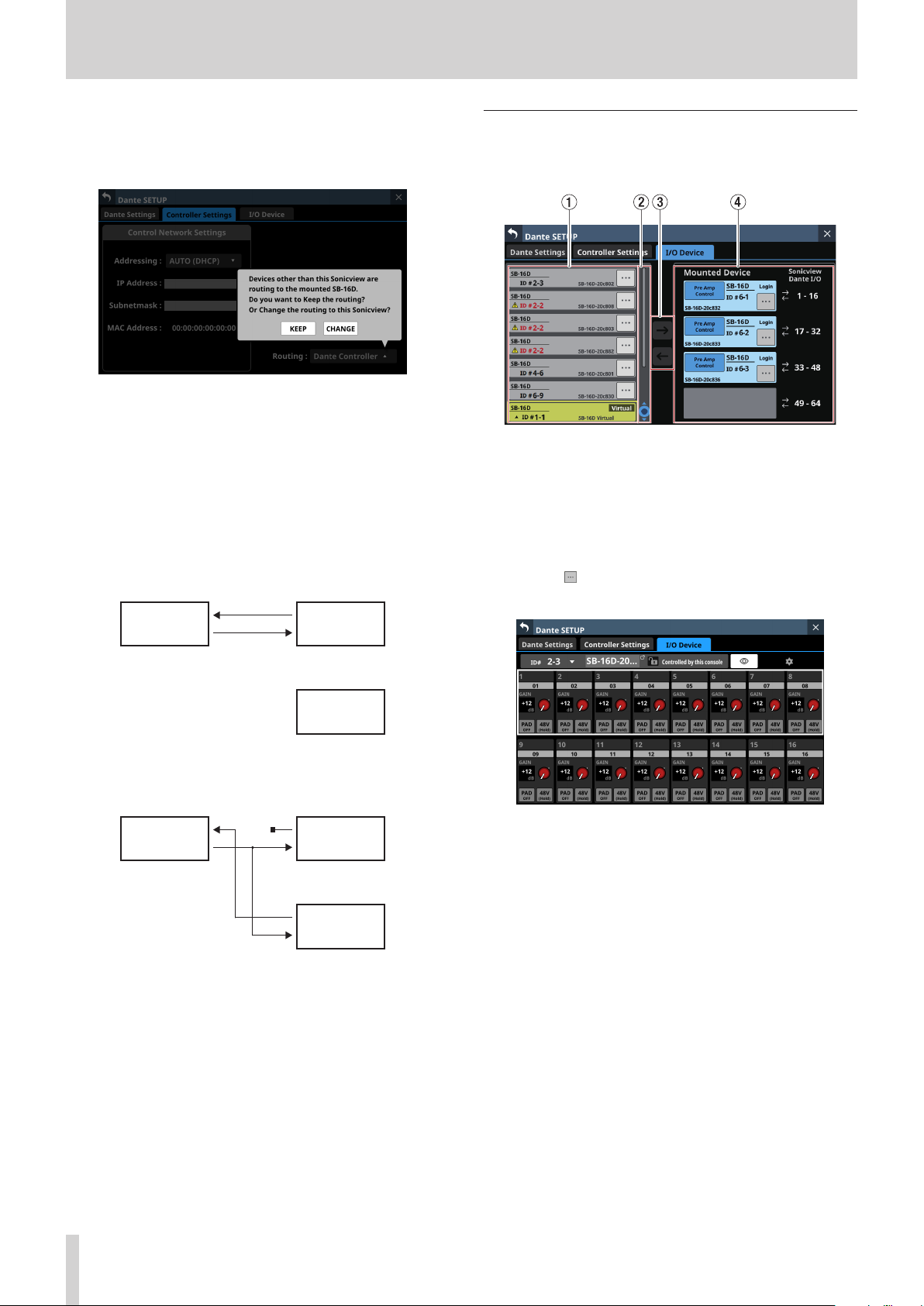
4 – Mixer configuration and settings
o When the setting is changed from “Dante Controller” to
“This Console”, the following confirmation message will
appear if executing automatic Dante routing changes the
Dante input routing of this unit.
Tapping the KEEP button will switch routing control
to “This Console” but the Dante routing setting will be
retained as is. If an SB-16D is mounted after switching to
“This Console”, routing will occur automatically.
Tapping the CHANGE button will change the Dante
routing according to the mounting status. In this case,
output routing from the Sonicview to other Dante
devices will be retained as is, and output routing from the
Sonicview to mounted SB-16D unit will be added.
i Example of Dante routing when Routing control
setting is “Dante Controller”
Sonicview 16 /
Sonicview 24
Dante
device
I/O Device page
Use this page to, for example, mount SB-16Ds, which are
supported I/O devices, and make settings for them.
1 Device display area
o This shows the ID numbers, model names (SB-16D) and
Dante device module names for SB-16D units detected
on the connected Dante network. SB-16D units that have
different network addresses or are connected through
routers will not be shown here.
o Selected devices will be highlighted with yellow frames.
o Tap the button to open the SB-16D control screen. (See
“Control screen operations” on page 71.)
Mounted
SB-16D
i Dante routing state when the Routing control setting
is switched to “This Console” from the above state and
the CHANGE button is tapped
Sonicview 16 /
Sonicview 24
Dante
device
Mounted
SB-16D
2 Scroll knob and scrollbar
o If all the detected Dante devices cannot be shown on the
screen at once, the scrollbar will appear and the scroll
knob will be highlighted.
o Drag the scrollbar to scroll the screen. The device display
area (1) can also be scrolled by swiping up and down as
well as by turning LCD knob 4.
3 Mount/unmount buttons
Use these buttons to mount SB-16D units and to unmount
already mounted ones.
See the following for operation procedures.
o “Mounting of devices connected to the Dante network” on
page 62
o “Unmounting devices” on page 63
o “Mounting devices that are not on the Dante network” on
page 64
60 TASCAM Sonicview 16/Sonicview 24 V1.1.0

4 – Mixer configuration and settings
4 Mounted Device area
This shows mounted devices.
The devices are shown with the following colors depending
on status.
Item Status
Device connected to the Dante
network
Virtual device that does not exist
on the Dante network
Selected devices and mounting positions will be highlighted
with yellow frames.
c This shows the login status.
Item Explanation
Login
Logout
d This shows the module name of the Dante device set in
this SB-16D.
e This shows the ID. If multiple devices with the same ID
are connected to the same Dante network (when the
same ID is duplicated), “ID” will be shown in red with a
mark.
f Tap this button to open the SB-16D control screen. (See
“Control screen operations” on page 71.)
Information for this SB-16D can be
acquired by this Sonicview.
Information for this SB-16D cannot be
acquired by this Sonicview. (Login is not
possible because this SB-16D is already
mounted by 10 Sonicview units or a
communication error occurred.) (See
“Login failure” on page 67.)
Using SB-16D units
To use SB-16Ds as a Sonicview I/O boxes, they must be mounted
(registered) in advance.
See the following for operation procedures.
i “Mounting of devices connected to the Dante network” on
page 62
i “Mounting devices that are not on the Dante network” on
page 64
a Control privilege display area: This shows the control
privilege status.
Item Explanation
This Sonicview has control
privileges.
This Sonicview does not have
control privileges. The named
Sonicview has control privileges.
Tap this to open a message
confirming whether or not to
request control. (See “Setting
control privileges after mounting”
on page 64.)
No device has control privileges. Tap
this to open a message confirming
whether or not to request control.
(See “Setting control privileges after
mounting” on page 64.)
b This shows the module name. If no device with the
same ID is connected to the same Dante network
(when virtually-mounted), “Virtual” will be shown.
o A maximum of 4 SB-16D units can be mounted on a
Sonicview.
o If an SB-16D is mounted and control privileges acquired, this
unit will be able to do the following.
i Control SB-16D preamps
i Control SB-16D preamps using snapshot recall
i Control/use GPIO ports (expansion mode)
i Control Dante output routing
o The Sonicview manages SB-16D mounting status by ID. If
no device with the same ID as the mounted ID is connected
to the Dante network, “Virtual” will be shown instead of the
device name.
o If multiple devices with the same ID are connected to the
same Dante network (when the same ID is duplicated), “ID”
will be shown in red with marks for those devices.
o If the ID of a mounted device is used by more than one
device, the SB-16D that was recognized by the Sonicview
first will be used. However, duplicate IDs must be resolved
to show them on the SB-16D control screen. (See “Resolving
duplicate IDs” on page 65.)
Moreover, an SB-16D with a duplicate ID that is later
recognized by the Sonicview cannot be used.
o If the Routing control setting on the Controller Settings page
is “This Console”, the mounted SB-16D I/O ports and the main
unit’s built-in Dante I/O will be assigned to Dante routing
automatically when mounted according to the mounting
position in the Mounted Device area (4). See the table in
“Dante routing” on page 68 for details.
TASCAM Sonicview 16/Sonicview 24 V1.1.0 61

4 – Mixer configuration and settings
Mounting of devices connected to the Dante
network
1. Tap a device in the left column on the Dante network that
you want to mount.
The selected device will be shown with a yellow frame.
2. Tap the mounting destination on the right side (open
mounting slot).
The selected mount destination will be shown with a yellow
frame, and the central button will become highlighted ( ).
3. Tap the central button to mount it in the selected
destination on the right side.
5. Tap the REQUEST button to start requesting control
privileges.
Tap the CANCEL button to cancel requesting control
privileges.
NOTE
If control privileges are not acquired, control of the preamps,
GPIO (expansion mode), snapshot recall and output routing
will not be possible from this Sonicview even when mounted.
If control privileges are acquired, control of the above items
becomes possible, and sampling rate and reference level
settings will be prioritized over those from other Sonicview
units.
o If the Sonicview with control privileges is not on the Dante
network:
Control privileges will be acquired in about one second
and a message will appear. This message will disappear
automatically after a few seconds.
Information about control privileges after mounting will be
shown in the top left of the mounting slot.
Item Explanation
Pre Amp Control
Pre Amp Control by
[device name]
If this Sonicview has control privileges, this completes
mounting.
4. If control privileges are set to a different Sonicview, a
message confirming whether or not to acquire control
privileges will appear.
Control is possible from this
Sonicview.
The named Sonicview has control
privileges. Control is not possible
from this Sonicview. (Sound will
pass.)
o If the Sonicview with control privileges is on the Dante
network:
The unit will wait for permission from the Sonicview with
control privileges. A message will appear while waiting
for permission. Tapping the CANCEL button will stop the
permission waiting state and end the mounting operation.
62 TASCAM Sonicview 16/Sonicview 24 V1.1.0

4 – Mixer configuration and settings
A permission request message will appear on the Sonicview
with control privileges.
i This message will disappear automatically if the CANCEL
button is tapped on the requesting device before the
response is given on the Sonicview with control privileges.
i If a button in the permission request message on the
Sonicview with control privileges is tapped, the following
will appear on the requesting Sonicview.
i Tapping the ALLOW button will cause a message
confirming that control has been acquired to appear
on the requesting device. This message will disappear
automatically after 2 seconds.
Unmounting devices
1. Tap the device that you want to unmount in the right
column list.
The selected device will be shown with a yellow frame, and
the central button will become highlighted ( ).
2. Tap the central button.
This unmounts the selected device, moving it to the list on
the left.
i Tapping the DENY button will open a message
confirming refusal of the request. Tap the OK button to
close the message.
If control privileges were held before unmounting, they will
be cleared.
“No one has control.” will be shown in the control privilege
display area on other Sonicview units that have this device
mounted.
TASCAM Sonicview 16/Sonicview 24 V1.1.0 63

4 – Mixer configuration and settings
Mounting devices that are not on the Dante
network
Devices that are not connected to the Dante network can be
mounted virtually.
Connecting a device with a corresponding ID when the
Controller Settings page Routing control setting is “This Console”
will cause preamp and routing information to be applied.
1. Tap the ID at the very bottom of the list on the left to open
a window where an ID number can be set for a virtuallymounted device.
2. Swipe the options up and down to select the ID to mount.
Selections can also be changed by turning the LCD Knobs 2
and 3, which are lit pink and yellow.
If an ID that is already being used on the Dante network
is selected, that ID will be red and the APPLY button will
appear gray, showing the setting cannot be made.
3. Tap the APPLY button to confirm setting changes.
The selected ID number will be shown.
Setting control privileges after mounting
Control privileges can be requested after mounting.
1. Tap the control privilege display area for a mounted SB-16D
with control privileges that have not been acquired to open
a message.
2. Tap the REQUEST button to start requesting control
privileges.
Tap the CANCEL button to cancel requesting control
privileges.
NOTE
If control privileges are not acquired, control of the preamps,
GPIO (expansion mode), snapshot recall and output routing
for that SB-16D will not be possible from this Sonicview even
when mounted.
If control privileges are acquired, control of the above items
becomes possible, and sampling rate and reference level
settings for that SB-16D will be prioritized over those from
other Sonicview units.
4. Tap the mounting destination on the right side (open
mounting slot).
The selected mount destination will be shown with a yellow
frame, and the central button will become highlighted ( ).
5. Tap the central button to mount it in the selected
position on the right side.
64 TASCAM Sonicview 16/Sonicview 24 V1.1.0

4 – Mixer configuration and settings
Resolving duplicate IDs
o Resolving in the list on the right
1. Tap the button for a device with a duplicate ID to open
the ID setting window.
2. Swipe the options up and down to set the ID as desired.
Selections can also be changed by turning the LCD Knobs 2
and 3, which are lit pink and yellow.
NOTE
If an ID that is already being used on the Dante network is
selected, that ID will be red and the APPLY button will appear
gray, showing the setting cannot be made.
3. Tap the APPLY button to confirm setting changes.
The selected ID number will be shown.
o Resolving in the list on the left
1. Tap the button for a device with a duplicate ID.
This opens the control screen for the tapped device.
2. If “Controlled by this console” is shown to the right of the
device name area, tap the ID area at the top left of the
screen to open the ID setting window.
This resolves the duplication, and returns to the regular
screen.
3. Swipe the options up and down to set the ID as desired.
Selections can also be changed by turning the LCD Knobs 2
and 3, which are lit pink and yellow.
NOTE
If an ID that is already being used on the Dante network is
selected, that ID will be red and the APPLY button will appear
gray, showing the setting cannot be made.
4. Tap the APPLY button to confirm setting changes.
The selected ID number will be shown.
This resolves the duplication, and returns to the regular
screen.
TASCAM Sonicview 16/Sonicview 24 V1.1.0 65

4 – Mixer configuration and settings
Alerts and errors shown related to the SB-16D
o When switching from virtual mounting to actual mounting:
The following message window will appear on the right
touchscreen.
Tap the CLOSE button to close the message.
Tap the Dante Setup button to open the Dante SETUP Screen
I/O Device page on the right touchscreen. In addition, the
following alert message will appear at the top of every
touchscreen.
SB-16D ID #xx-xx connected.
Tap this alert message to open the Dante SETUP Screen I/O
Device page.
To close the alert message shown at the top of the screen,
tap the button on the corresponding message on the
ERROR page of the INFORMATION screen. (See “ERROR page”
on page 185.)
after the alert message is removed.
This error message can be resolved in the following ways.
i Resolving the duplicate ID using the I/O DEVICE page of
the Dante screen will close the error message at the top of
the screen.
i If the device causing duplication is removed from the
Dante network, normal mounting status will be restored
and the error message at the top of the screen will be
closed.
i When this error message is resolved, the following error
resolution message will be added to the ERROR page of
the INFORMATION screen.
SB-16D ID #xx-xx conflict has been resolved.
Restrictions when routing during 96kHz
operation with Dante Controller
o When routing control is set with Dante Controller, “Sonicview
Dante I/O” and “ 1–16”, for example, will not be shown in
the list on the right of the I/O Device page.
o When switching from actual mounting to virtual mounting:
When a mounted SB-16D is disconnected from the Dante
network and becomes virtually mounted, the following error
message will appear at the top of every touchscreen.
SB-16D ID #xx-xx has been disconnected.
Tap this error message to open the Dante SETUP Screen I/O
Device page.
This error message can be resolved in the following ways.
i If the SB-16D returns to the Dante network, the error will
be resolved automatically and the error message at the
top of the screen will disappear.
i Tapping the button on the corresponding error
message on the ERROR page of the INFORMATION screen
will close the error message at the top of the screen.
i Unmounting the corresponding device using the I/O
DEVICE page of the Dante Setup screen will resolve the
error and close the error message at the top of the screen.
o When an ID is used more than once:
When another SB-16D that has the same ID as a mounted
SB-16D is connected to the Dante network, resulting in
duplicate IDs, the following error message will appear at the
top of every touchscreen.
SB-16D ID #xx-xx has been conflicted.
Tap this error message to open the Dante SETUP Screen I/O
Device page.
In this case, the device that was mounted first is given
priority, so it has no impact on operation as a mixer.
If an ID becomes duplicated when there is a remaining
alert message that occurred when switching from virtual
mounting to actual mounting, the error message will appear
Instead this message will be shown: “Use the Dante
Controller for Routing.”
o If the Sampling rate is set to “96kHz” on the Dante Settings
page of the Dante SETUP screen, the list on the right of the
I/O Device page will not show “ 33–48” and “ 49–64” in the
bottom two mounting slots.
Alternatively, the message shown below will appear.
In this case, operations to acquire control privileges are
necessary after mounting.
They will not be acquired automatically when mounted.
Immediately after mounting, “Pre Amp Control OFF” will be
shown in the control privilege display area.
i If no IF-DA64 (Dante card) is installed:
Tapping the control privilege display area will open the
following message.
IF-DA64 is required to enable Pre Amp Control.
[CANCEL]
66 TASCAM Sonicview 16/Sonicview 24 V1.1.0

4 – Mixer configuration and settings
Tap the CANCEL button to close the message window and
return to the previous screen. In this case, preamp control
is not possible from this unit.
i If an IF-DA64 (Dante card) is installed:
Tapping the control privilege display area will open the
following message.
Route as follows by Dante Controller.
[SB-16D 1-16ch] to[ IF-DA64 (Slot1) 1-16ch]*
Do you want to enable Pre Amp Control?
[CANCEL] [ENABLE]
i Tap the CANCEL button to close the message window
and return to the previous screen. In this case, preamp
control is not possible from this unit.
i Tapping the ENABLE button will set the control
privilege and “Pre Amp Control” will be shown in the
control privilege display area.
i If another Sonicview, for example, already has SB-16D
control privileges:
Tapping the control privilege display area will open the
following message.
Route as follows by Dante Controller.
[SB-16D 1-16ch] to [IF-DA64 (Slot1) 1-16ch]*
Do you request control?
Sonicview XXX has Pre Amp control.
[CANCEL] [REQUEST]
Login failure
One SB-16D can be accessed simultaneously from a maximum
of 10 Sonicview units.
If 10 units would be exceeded, the Sonicview that tries to access
that SB-16D will fail (login failure) and will not be able to control
that SB-16D.
“Logout” will be shown at the top right of mounted devices for
which logging in failed.
Tap the button for unmounted or mounted devices to show
the following messages that explain generally why login failed.
Tap the OK button in the message to close it.
The content of the message depends on the reason login failed.
o If 10 units are already logged in
Login failed. Max number of connections.
After this, control privileges can be acquired by following
the procedures from step 5 in “Mounting of devices
connected to the Dante network” on page 62.
By acquiring control privileges with the above methods,
preamp control becomes possible from the assigned module
of the SLOT that the IF-DA64 (Dante card) is installed in as an
input source.
* This appears when an SB-16D is mounted in the 3rd
mounting slot and an IF-DA64 (Dante card) is installed in
SLOT 1.
If an SB-16D is mounted in the 4th mounting slot and
an IF-DA64 (Dante card) is installed only in SLOT 2, the
following message will appear.
Route as follows by Dante Controller.
[SB-16D 1-16ch] to [IF-DA64 (Slot2) 17-32ch]
o If login was not possible because of a communication error
Login failed. TCP Error.
If logging in fails when an SB-16D is mounted, mounting will be
executed, but the above messages will be shown.
The following items are possible or not possible using mounted
devices with which login failed.
o Possible
i Input Dante Routing from the SB-16D to the Sonicview
can be set with this unit, and the input sound of this SB16D can be input to this unit.
i Setting routing with Dante Controller makes inputting
and outputting sound from this SB-16D possible.
o Not possible
i Output Dante routing from the Sonicview to the SB-16D
cannot be set with this unit. For this reason, sound from
this unit cannot be output from this SB-16D.
i Acquiring control privileges and changing/confirming
preamp and other settings are not possible.
Responding to login failure errors
o If any Sonicview units are showing the operation screen for
that unmounted SB-16D, close that screen.
o If that SB-16D is mounted on more than 10 Sonicview units,
unmount it from a Sonicview unit that does not need it.
o If already mounted and logging in failed, after doing the
above, unmount it and then mount it again.
o If the above responses do not resolve the issue, turn the SB-
16D power off once and wait a few seconds before turning
the power on again.
TASCAM Sonicview 16/Sonicview 24 V1.1.0 67

4 – Mixer configuration and settings
Synchronizing audio settings
If the Sonicview has control privileges after mounting, the
SB-16D sampling rate and reference level (both analog and
digital) settings will automatically be synchronized with those
of that Sonicview. Moreover, it will also be set as the device for
snapshot recall and set as the device with priority for Dante
output routing.
Dante routing
Routing of Dante I/O for mounted SB-16Ds and the Sonicview
can be done automatically.
On the other hand, routing can be left to Dante Controller and
the Sonicview can be set to not do routing.
Use the Routing control setting on the Controller Settings page
to set this. (See “2 Routing control setting” on page 59.)
o To conduct Dante routing from the Sonicview for SB-16D
units mounted on it, set the Routing control setting to “This
Console”.
Dante routing will be set automatically when mounted.
In this case, depending on the SB-16D mounting position,
the mounted SB-16D I/O port and this unit’s built-in Dante
I/O will be routed for Dante automatically when mounting
occurs as shown below.
When Sync Clock is 48 kHz
Mounting position in
Mounted Device area
4th from top
NOTE
When the Routing control setting is changed from “Dante
Controller” to “This Console”, if executing automatic Dante
routing changes the Dante input routing of this unit, the
following message will appear, confirming whether to match
routing with the mounting status.
Devices other than this sonicview are routing to the
mounted SB-16D.
Do you want to KEEP the routing? Or Change the routing to
this Sonicview?
[KEEP] [CHANGE]
Tapping the KEEP button will switch routing control to “This
Console” but the Dante routing setting will be retained as
is. If an SB-16D is mounted after switching to “This Console”,
routing will occur automatically.
Tapping the CHANGE button will change the Dante routing
according to the mounting status. In this case, output routing
from the Sonicview to other Dante devices will be retained
as is, and output routing from the Sonicview to mounted SB16D unit will be added.
i Example of Dante routing when Routing control setting is
“Dante Controller”
Sonicview 16 /
Sonicview 24
Routing destination
This will not be routed
automatically. Use Dante
Controller to route Dante I/O
17–32 for the IF-DA64 installed
in this unit and Dante I/O 1–16
for the mounted SB-16D.
Dante
device
Mounting position in
Mounted Device area
Top
2nd from top
3rd from top
4th from top
When Sync Clock is 96 kHz
Mounting position in
Mounted Device area
Top
2nd from top
3rd from top
Routing destination
Built-in Dante I/O 1–16 of this
unit
Built-in Dante I/O 17–32 of this
unit
Built-in Dante I/O 33–48 of this
unit
Built-in Dante I/O 49–64 of this
unit
Routing destination
Built-in Dante I/O 1–16 of this
unit
Built-in Dante I/O 17–32 of this
unit
This will not be routed
automatically. Use Dante
Controller to route Dante I/O
1–16 for the IF-DA64 installed in
this unit and Dante I/O 1–16 for
the mounted SB-16D.
Mounted
SB-16D
i Dante routing state when the Routing control setting is
switched to “This Console” from the above state and the
CHANGE button is tapped
Sonicview 16 /
Sonicview 24
o To conduct Dante routing for the Sonicview from Dante
Controller, set the Routing control setting to “Dante
Controller”.
This will enable routing from Dante Controller.
i When set to conduct Dante routing from Dante Controller,
routing settings cannot be conducted from the Sonicview
even for SB-16D units.
NOTE
Routing for mounted SB-16Ds will be retained as is. If an
SB-16D is mounted after the routing control setting is set to
“Dante Controller”, routing will not occur automatically.
Dante
device
Mounted
SB-16D
68 TASCAM Sonicview 16/Sonicview 24 V1.1.0

4 – Mixer configuration and settings
SB-16D control
Preamp control as a Sonicview I/O expansion
From the operation screen of the module that has the built-in
Dante input port routed, input connector preamps of SB-16Ds
that have been routed by Dante to this Dante input port can be
operated.
In this case, they can be operated in the same way as the built-in
analog input preamps of the Sonicview.
Only if all the following conditions are all met, preamps can be
operated on the Home Screen, MODULE (OVERVIEW) screen and
Module (INPUT) screen.
o A Dante port is assigned to the module
o The SB-16D Dante port is routed to this Dante port
o The SB-16D that is routed to this Dante port is mounted on
the Sonicview and control privileges are held, or it is virtually
mounted
Example of appearance when mounted and control
privileges are held
In this case the same preamp settings will be shown as would be
when routing the built-in analog input jacks.
Example of appearance when mounted but control
privileges are not held
In this case, the SB-16D preamp settings can be shown, but the
GAIN knob, PAD buttons and 48V buttons will appear black and
cannot be operated.
TASCAM Sonicview 16/Sonicview 24 V1.1.0 69

4 – Mixer configuration and settings
Example of appearance when virtually mounted
In this case the same preamp settings will be shown as would be
when routing the built-in analog input jacks, and marks are
shown on routing settings.
SB-16D full control
Whether they are mounted or not, SB-16D units that are
connected to the same Dante network can be fully controlled
from a Sonicview.
NOTE
If another Sonicview has SB-16D control privileges, its setting
values can be shown, but they cannot be controlled. In this
case, an icon will appear at the top of the SB-16D control
screen and the Dante device module name of the Sonicview
that has control privileges will be shown.
1. Tap Menu Screen > Rear Panel Setup > Dante Setup to open
the Dante SETUP screen and tap the I/O Device tab.
2. Tap the button for the device you want to control.
This opens the control screen.
70 TASCAM Sonicview 16/Sonicview 24 V1.1.0

4 – Mixer configuration and settings
Control screen operations
1 ID
o This shows the current ID.
o Tap this area to open a window where the ID can be
changed.
4 button
o Tap this button to send an Identify command to the SB-
16D. The SB-16D that receives the Identify command will
respond by blinking its SIG and STATUS indicators, making
it possible to confirm the corresponding device. Tapping
this button again when an SB-16D is responding will send
it another Identify command, which will cause it to stop
responding.
o This button is not shown for devices that are virtually
mounted.
5 button
Tap this button to open the Settings Screen where settings
other than those related to preamp operation can be
checked.
Swipe the options up and down to change the ID.
Selections can also be changed by turning the LCD Knobs
2 and 3, which are lit pink and yellow.
i Tap the APPLY button to change the selected ID.
i Tap the CANCEL button to close the window without
changing the ID.
NOTE
i If an ID that is already being used on the Dante network is
selected, that ID will be red and the APPLY button will appear
gray, showing the setting cannot be made.
i Changing the ID when mounted could cause it to become
unmounted.
2 Device name
o This shows the module name of the SB-16D Dante device.
o Tap this area to enable changing the module name of the
Dante device.
o If the device is virtually mounted, “---” will appear and
tapping will not enable changing.
3 Control privilege status
o This shows the control privilege status.
o If this unit has control privileges, and “Controlled by this
console” will be shown.
o If this unit does not have control privileges, and
“Controlled by [Dante device module name of the
Sonicview that has control privileges]” will be shown.
o In the following cases, nothing will be shown.
i If no device has control privileges for that SB-16D
i If the device is virtually mounted
6 Channel modules
o Work with channel names, GAIN knobs, PAD buttons and
48V buttons in this area.
i Tapping a channel name will open the RENAME screen
where it can be edited.
i GAIN levels of the channels selected by the frame can
be adjusted using the 1–8 LCD knobs that are lit red.
i Tap a PAD button to turn the -20dB pad on/off. When
this button is on, it will appear highlighted.
i Touch and hold the 48V button to turn phantom power
(+48V) on/off. When phantom power is on, the button
will be highlighted.
o GAIN knobs, PAD buttons and 48V buttons can also be
used with virtually mounted devices.
o If another Sonicview has control privileges for the SB-16D
shown, it will appear as follows and cannot be controlled.
Example of appearance when control privileges are not held
TASCAM Sonicview 16/Sonicview 24 V1.1.0 71

4 – Mixer configuration and settings
Settings screen
1 Firmware Version
This shows the SB-16D firmware versions.
If the device is virtually mounted, “---” will appear in place of
the numbers.
2 Serial No.
This shows the serial number of the SB-16D.
“---” will appear if the device is virtually mounted.
3 Dante Version
o This shows the SB-16D Dante module firmware version.
If the device is virtually mounted, nothing will be shown
even if tapped.
o Tap this area to open a Dante information window.
4 Scroll knob and scrollbar
This scroll bar shows the position of the setting items
currently shown on the screen relative to all items on the
Settings Screen.
NOTE
To view setting items not shown on the screen, swipe the
setting items area up and down to scroll the screen.
LCD knob 8, which is lit light blue, can also be turned to scroll
the screen.
5 DC Power information
SB-16D DC power status is shown and related settings can be
made here.
Item Explanation
This shows the current voltage and
status of the DC power supply.
A green indicator will be shown if the
DC power supply is providing power
normally.
DC Volt.
Stop Volt.
Alert Volt.
Settings button
“---” will appear for all the settings if the device is virtually
mounted. In addition the Settings button will appear gray
and cannot be used.
If the alert display setting is on, and the
DC power supply voltage has become
less than the alert voltage, an
indicator will be shown.
No indicator will be shown if the DC
power supply is not providing power (if
the DC power supply voltage is below
the stop voltage).
This shows the stop voltage setting
value.
This shows the setting value for the
voltage that triggers showing an alert.
If the Alert Voltage ON/OFF button is
set to “OFF” in the DC Power settings
window, “--.-V” will be shown here.
Tap this button to open the DC Power
settings window. (See “DC Power
settings” on page 73.)
6 Sampling rate buttons
These set the sampling frequency for the SB-16D.
The selected button will be highlighted.
7 Digital Reference buttons
Use these to set the digital reference level of the SB-16D.
The selected button will be highlighted.
8 Analog Reference buttons
Use these to set the analog reference level of the SB-16D.
The selected button will be highlighted.
72 TASCAM Sonicview 16/Sonicview 24 V1.1.0
NOTE
i The settings of Sampling rate (6), Digital Reference (7)
and Analog Reference (8) buttons with green backgrounds
are linked to the settings of the Sonicview that has control
privileges. For this reason, settings cannot be changed on
this Settings screen if mounted.
i For virtually mounted devices, Sampling rate (6), Digital
Reference (7) and Analog Reference (8) button settings will
all appear gray and cannot be operated.

4 – Mixer configuration and settings
9 LED Brightness buttons
o Use the and buttons to set the brightness of the SB-
16D indicators.
Range: 0 – 3 (in steps of 1, default 3)
o If the device is virtually mounted, “–” will appear and the
buttons will be gray and cannot be operated.
0 GPIO EXTENSION
Tap the Settings button to open the GPIO Extension Settings
Screen. (See “GPIO Extension Settings Screen” on page 74.)
Virtually-mounted devices can also be operated.
q Network Settings
o Tap the Dante button to open the Dante Network Settings
on the Network Settings Screen. (See “Dante Network
Settings” on page 76.)
o Tap the Controller button to open the Controller Network
Settings on the Network Settings Screen. (See “Control
Network Settings” on page 77.)
o If the device is virtually mounted, the Dante and
Controller buttons will be gray and the settings screen
cannot be opened.
w Factory Reset button
Tap the Reset button to open a window where settings can
be restored to their factory default values. (See “Factory
Reset” on page 78.)
If the device is virtually mounted, this button will be gray and
cannot be operated.
DC Power settings
Tap the Settings button in the DC Power area to open the
following DC Power settings window.
a Stop Voltage: This sets the stop voltage.
Use LCD knob 4, which is lit light blue, to adjust it.
Range: 11.0 – 27.0 V (in steps of 0.1 V, default 11.0 V)
If the SB-16D is operating with only DC power supply, it
will shut down if the DC power supply goes below this
voltage.
If DC power is supplied from a battery, set the stop
voltage according to the battery specifications. In all
other cases, set this to a minimum of 11.0 V (the default
value).
b Alert Voltage: This sets the alert voltage.
Use LCD knob 5, which is lit green, to adjust it.
Range: OFF, 11.0 – 28.0 V
(in steps of 0.1 V, default 11.5 V)
When the Stop Voltage setting is changed, this is
automatically set +0.5V higher than the Stop Voltage.
Change this setting to adjust the timing if the alert is
shown too quickly or too late.
c DC Voltage: This shows the current DC input voltage.
d Alert Voltage ON/OFF button: Tap this button to turn
the alert message on/off. (Default: ON)
When ON, if the DC power supply voltage becomes
less than the alert voltage, the following alerts will be
shown.
i SB-16D DC POWER indicator blinks
i indicator appears in DC Power area (5)
e Alert Reset button: Tap this button to reset the Alert
Voltage setting to the default value (Stop Voltage +0.5
V).
f CANCEL button: Tap this button to discard the changes
in the DC Power settings window and close it.
g SET button: Tap this button to confirm the values in the
DC Power settings window and close it.
TASCAM Sonicview 16/Sonicview 24 V1.1.0 73

4 – Mixer configuration and settings
GPIO Extension Settings Screen
The SB-16D GPIO port has the following functions.
GPIO-IN
i Muting control of SB-16D input and output signals (Local
mode function)
i Mounted Sonicview extension GPIO-IN port operation
(Extension mode function)
GPIO-OUT
i Tally output for muting states of SB-16D input and output
signals (Local mode function)
i Mounted Sonicview extension GPIO-OUT port operation
(Extension mode function)
The following settings to use these functions can be made on
this screen.
ALL Extension mode
1 ID
o This shows the current ID.
o Tap this area to open a window where the ID can be
changed.
Swipe the options up and down to change the ID.
Selections can also be changed by turning the LCD Knobs
2 and 3, which are lit pink and yellow.
i Tap the APPLY button to change the selected ID.
i Tap the CANCEL button to close the window without
changing the ID.
NOTE
i If an ID that is already being used on the Dante network is
selected, that ID will be red and the APPLY button will appear
gray, showing the setting cannot be made.
i Changing the ID when mounted could cause it to become
unmounted.
2 GPIO port overall operation mode
o This shows the overall operation mode for the GPIO port.
o Tap this area to open a window where the overall
operation mode for the GPIO ports of the SB-16D can be
changed.
ALL Local mode
Individual mode
74 TASCAM Sonicview 16/Sonicview 24 V1.1.0
Option Explanation
The ALL Extension mode setting uses all
ALL Extension
ALL Local
Individual
Tap an option to switch the overall operation mode for the
GPIO port of the SB-16D.
GPIO ports as GPIO extension pins of the
Sonicview that the SB-16D is mounted
in.
The ALL Local mode setting uses all GPIO
ports as pins that do the following.
i GPIO-IN: SB-16D input/output signal
muting control
i GPIO-OUT: Tally output for muting
states of SB-16D input/
output signals
In this mode, the operation of each GPIO
port is set individually.

4 – Mixer configuration and settings
3 Pin number buttons
o Tap this area to select a pin and enable setting its action
mode switching button (4), input/output signal selection
status (5) and operation mode switching button for the
individual port (6).
o When the overall operation mode for GPIO ports is “ALL
Local” or “Individual”, tapping a pin number button will
outline that button with a white frame.
4 ACTION mode switching buttons
o These show the operation mode for the selected GPIO
port in the following cases.
i When GPIO port overall operation mode (2) is “ALL
Local”
i When GPIO port overall operation mode (2) is
“Individual” and the operation mode (6) for individual
ports is “Local”
o This shows the action mode of the selected GPIO Port.
o Tap this button to open a window for setting the action
mode.
5 Input/output signal selection status
These show the operation mode for the selected GPIO port in
the following cases.
o When GPIO port overall operation mode (2) is “ALL Local”
o When GPIO port overall operation mode (2) is “I ndividual”
and the operation mode (6) for individual ports is “Local”
When a GPIO-IN pin is selected, the SB-16D input/output
signal that is subject to muting control is selected according
to that pin.
Up to 16 can be selected for muting control by GPIO-IN pin.
If the selectable number is exceeded, the check fields will be
shown in gray and become unselectable.
When a GPIO-OUT pin is selected, this selects the SB-16D
input/output signal for mute status tally output from the
selected pin. In this case, only one can be selected. Multiple
selection is not possible.
For GPIO IN ports
Option Explanation
In this mode, when the selected IN
port becomes shorted (Make), the
Make-Toggle
Make-Mute
Break-Mute
For GPIO OUT ports
Option Explanation
Mute-Make
Mute-Break
input/output signal selected in the
input/output signal selection status
area (5) is muted/unmuted.
In this mode, when the selected IN
port becomes shorted (Make), the
input/output signal selected in the
input/output signal selection status
area (5) is muted.
In this mode, when the selected
IN port becomes open (Break), the
input/output signal selected in the
input/output signal selection status
area (5) is muted.
In this mode, when the input/
output signal selected in the input/
output signal selection status area
(5) is muted, the selected OUT port
becomes shorted (Make).
In this mode, when the input/
output signal selected in the input/
output signal selection status area
(5) is muted, the selected OUT port
becomes open (Break).
6 Operation mode switching buttons for individual
ports
This is shown when “Individual” is selected for the overall
operation mode for the GPIO port (2).
Tap these buttons to switch the operation mode of the
selected port.
Option Explanation
The Extension mode setting uses the
Extension
Local
selected ports as GPIO extension pins of the
Sonicview that the SB-16D is mounted in.
The Local mode setting uses the selected
GPIO ports as pins that do the following.
i GPIO-IN: SB-16D input/output signal
muting control
i GPIO-OUT: Tally output for muting states
of SB-16D input/output signals
TASCAM Sonicview 16/Sonicview 24 V1.1.0 75
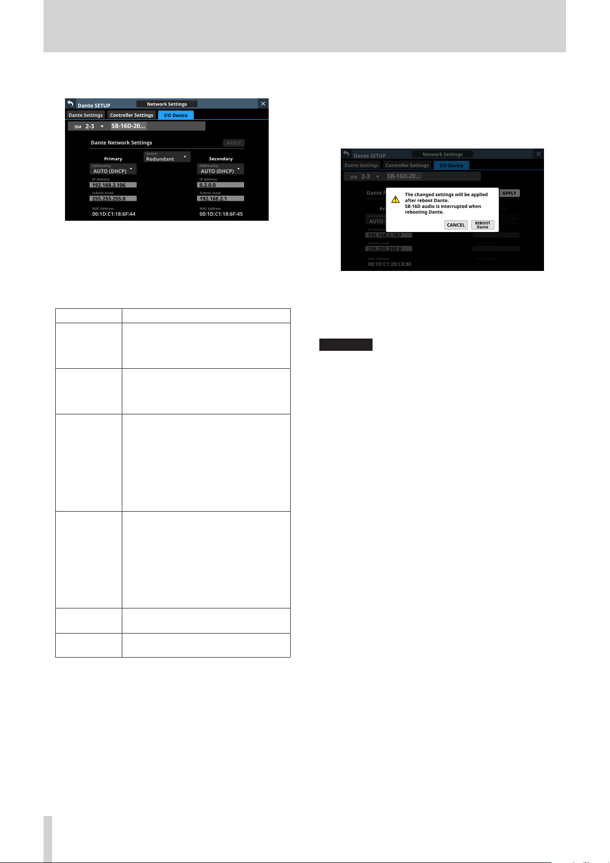
4 – Mixer configuration and settings
Dante Network Settings
This shows the status of the Dante network settings for the
SB-16D.
When in Redundant mode, settings will be shown for
the Primary connector on the left and for the Secondary
connector on the right.
When in Switched (daisy-chain) mode, only the left side will
be active.
Item Content
This shows the selected connection mode.
Switch
Addressing
IP Address
Subnet mask
LINK Status
MAC Address
Tap this area to open a window where
Redundant or Switched mode can be
selected. (default: Redundant)
This shows the IP address setting mode.
Tap this area to open a window where
AUTO (DHCP) or STATIC can be selected.
(default: AUTO (DHCP))
If the Addressing item is set to “AUTO”,
this will show the assigned IP address. If
it is set to “STATIC”, this will show the IP
address set by the user.
When the Addressing item is set to
“STATIC”, tapping this area will open the
IP ADDRESS Screen. (See “IP Address/
Subnet Mask/Default Gateway setting
procedures” on page 91.)
If the Addressing item is set to “AUTO”, this
will show the assigned subnet mask. If it
is set to “STATIC”, this will show the subnet
mask set by the user.
When the Addressing item is set to
“STATIC”, tapping this area will open the
SUBNET MASK Screen. (See “IP Address/
Subnet Mask/Default Gateway setting
procedures” on page 91.)
This shows the Dante network link status.
This will be shown in red if it is not 1 G.
This shows the MAC address of the
Primary/Secondary Dante port.
To confirm Dante network settings for the SB-16D, the SB16D Dante module must be restarted.
If SB-16D Dante network settings have been changed, the
APPLY button will appear highlighted.
Tap the APPLY button when it is highlighted to open a
confirmation message.
Since tapping the CANCEL button will not restart the unit,
the settings will be as is but will not be applied to operation.
Tap the REBOOT Dante button to confirm the changes and
restart the SB-16D Dante module.
After restarting, the settings will be applied to operation.
ATTENTION
Be aware that SB-16D Dante input and output sound will be
interrupted while the SB-16D Dante module is restarting.
76 TASCAM Sonicview 16/Sonicview 24 V1.1.0

4 – Mixer configuration and settings
Control Network Settings
This shows the status of the Dante network settings for SB16D control.
Item Content
This shows the IP address setting mode.
Addressing
IP Address
Subnet mask
MAC Address
Tap this area to open a window where
AUTO (DHCP) or STATIC can be selected.
(default: AUTO (DHCP))
If the Addressing item is set to “AUTO”,
this will show the assigned IP address. If
it is set to “STATIC”, this will show the IP
address set by the user.
When the Addressing item is set to
“STATIC”, tapping this area will open the
IP ADDRESS Screen. (See “IP Address/
Subnet Mask/Default Gateway setting
procedures” on page 91.)
If the Addressing item is set to “AUTO”,
this will show the assigned subnet mask.
If it is set to “STATIC”, this will show the
subnet mask set by the user.
When the Addressing item is set to
“STATIC”, tapping this area will open the
SUBNET MASK Screen. (See “IP Address/
Subnet Mask/Default Gateway setting
procedures” on page 91.)
This shows the MAC address for SB-16D
control.
If Dante network settings for SB-16D control have been
changed, the APPLY button will appear highlighted.
When settings are applied, the SB-16D Dante network
connection will be interrupted once. For this reason, tap the
APPLY button when it is highlighted to open a confirmation
message.
Tap the CANCEL button to cancel the changes and restore
the previous state.
Tap the APPLY button to confirm the changes.
TASCAM Sonicview 16/Sonicview 24 V1.1.0 77

4 – Mixer configuration and settings
Factory Reset
1. Tap the Reset button to open a window where settings can
be restored to their factory default values.
Item Explanation
If the check mark (4) is added,
the SB-16D Dante network
settings will be retained.
If the check mark (4) is
Keep Network Settings
Keep Dante Settings
(Include Routing)
2. Add check marks (4) for the settings that you want to
retain.
Remove check marks (4) for the settings that you want to
restore to factory defaults.
NOTE
If check marks (4) are added to both, only settings that are
not related to the Dante network and Dante will be restored
to their factory defaults.
removed, the SB-16D Dante
network settings will be
restored to their factory
defaults.
(This has a check (4) by
default.)
If the check mark (4) is added,
the SB-16D Dante settings will
be retained.
If the check mark (4) is
removed, the SB-16D Dante
settings will be restored to their
factory defaults.
(This does not have a check (4)
by default.)
3. Tapping the RESET or RESET & REBOOT button will open the
following warning messages in a window.
i Message if Keep Network Settings does not have a
check mark (4):
Network maybe disconnect.
i Message if Keep Dante Settings (Include Routing) does
not have a check mark (4):
Audio will be interrupt.
Dante routing will be cleared.
i Message when the RESET & REBOOT button is tapped:
Audio will be interrupt.
Message if Keep Network Settings does not have a check mark
(4)
4. Tap the RESET button in the warning message to close the
window and restore the following items to their factory
default settings.
i Settings without check marks (4)
i Settings other than those for Dante network and Dante
If the RESET & REBOOT button is tapped, after settings are
restored to their factory defaults, the I/O Device page of the
Dante Setup screen will open. Moreover, until the reset SB16D has completed restarting it will be disconnected from
the Dante network.
Tap the CANCEL button to close the window without
changing the settings.
78 TASCAM Sonicview 16/Sonicview 24 V1.1.0

4 – Mixer configuration and settings
Using GPIO extension functions
If the SB-16D GPIO pin operation mode is set to “Extension”, they
can be used as Sonicview GPIO extension pins.
This setting can also be made for virtually mounted SB-16D
units.
By storing the settings in the Sonicview, online setting is
possible.
Setting procedure
1. Following the instructions in “GPIO Extension Settings
Screen” on page 74 for the “Overall operation mode for
the GPIO port buttons” (2) or “ Operation mode switching
buttons for individual ports” (8), set the operation mode
for the ports you want to use as a GPIO extension for this
unit to “Extension”.
2. Use the following procedures to open GPIO-IN and GPIOOUT screens.
i Tap Menu Screen > Rear Panel Setup > GPIO Input
Setup
i Tap Menu Screen > Rear Panel Setup > GPIO Output
Setup
3. Use LCD knob 8 to scroll the list of settings for groups of 8
ports that correspond to mounting positions.
i In the SB-16D GPIO pin name area, SB-16D IDs and port
numbers are shown in a “#ID [port number]” format.
i If the device is virtually mounted, the GPIO port name
background will appear yellow.
i Ports with operation mode set to Extension in the list
will be highlighted.
i Ports with operation mode set to Local in the list will
be shown in gray.
4. Tap the port you want to set in the list and assign functions
using the same procedures as with the unit’s built-in GPIO.
TASCAM Sonicview 16/Sonicview 24 V1.1.0 79
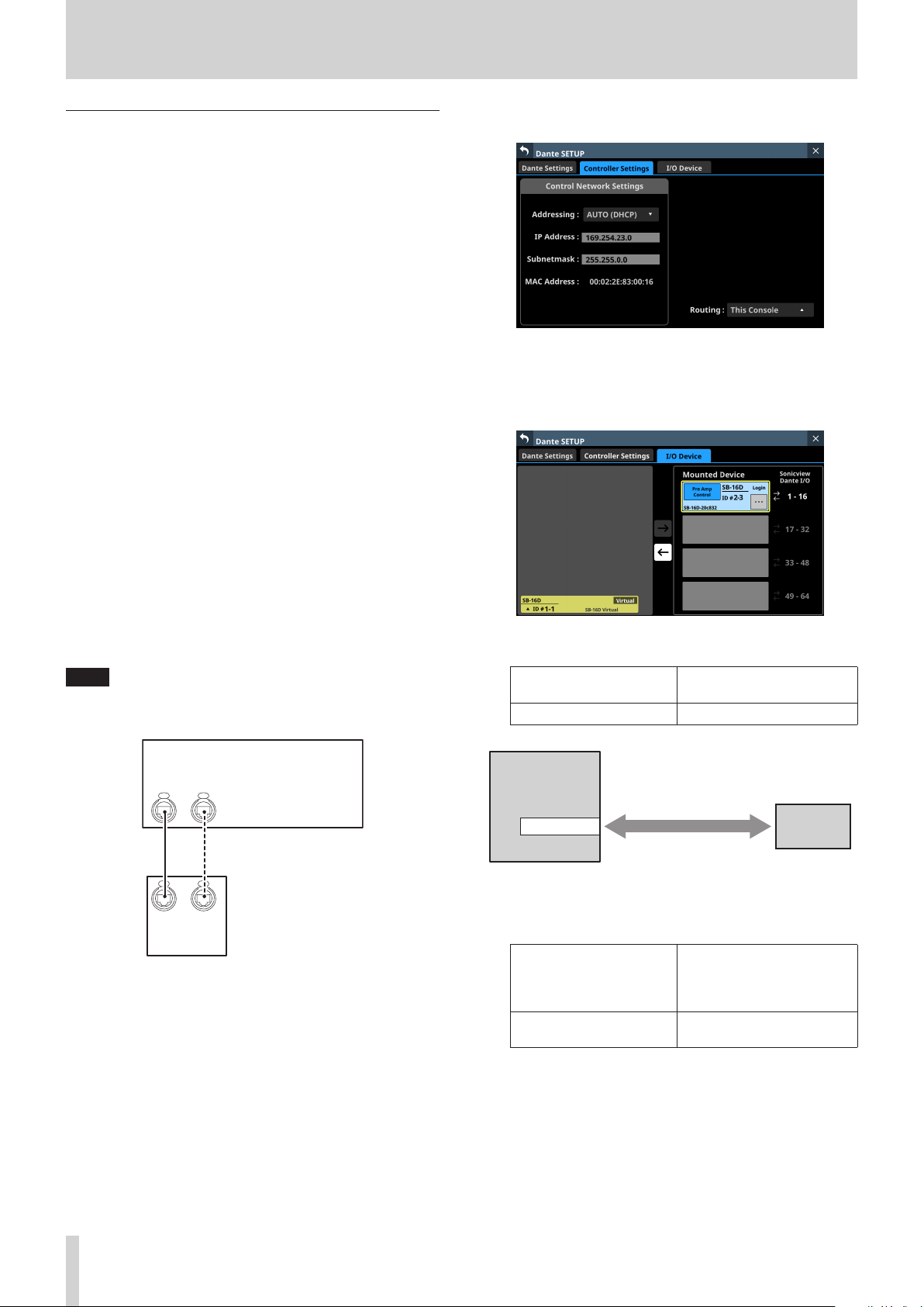
4 – Mixer configuration and settings
Procedures for Dante connection with SB-16Ds
This explains procedures for connecting an SB-16D as a stage
box to this unit, and controlling its preamps from modules with
built-in Dante ports assigned in the same way as built-in analog
inputs.
Dante connections with SB-16Ds
o When this unit is operating at 48 kHz, up to 4 SB-16D units
can be connected without Dante Controller.
o When this unit is operating at 96 kHz, up to 2 SB-16D units
can be connected without Dante Controller.
o In all other cases, setting using Dante Controller will be
necessary.
Procedures for Dante connection with this
unit and one SB-16D
In this case, Dante connection without using Dante Controller
is possible whether this unit’s built-in Dante “Sampling rate”
is using 48kHz or 96kHz operation. Moreover, controlling a
preamp of that SB-16D from a module with a built in Dante port
assigned is possible.
1. If multiple SB-16D units are connected to the Dante
network, set IDs that are not duplicated on them in advance
in order to enable their identification. For details about ID
setting procedures, see the SB-16D operation manual.
2. Connect the following Dante ports to the same Dante
network.
i Dante ports built into this unit
i SB-16D Dante ports
4. Set the Routing control setting to “This Console”.
5. Tap “I/O Device” to open the I/O Device page.
6. Follow the procedures in “Mounting of devices connected
to the Dante network” on page 62, and mount the
selected SB-16D as the top item in the Mounted Device list.
Through these procedures, the Dante I/O ports of this unit
and the one SB-16D unit are routed by Dante as follows.
NOTE
When using only one of these units and one SB-16D, their
Dante ports can be connected directly as shown below.
Sonicview
Dante
Dante
Primary
Secondary
Dante
Dante
Primary
Secondary
SB-16D
3. Set the Dante routing control method.
Tap Menu Screen > Rear Panel Setup > Dante Setup to open
the Dante SETUP screen and tap the Controller Settings tab.
Dante I/O ports of this
unit
SB-16D Dante I/O ports
Dante I/O 1–16 of this unit SB-16D Dante I/O 1–16
Sonicview
Automatic routing
when mounted
Dante I/O 1-16
As a result, the preamps (Analog GAIN, PAD ON/OFF,
Phantom ON/OFF) of the corresponding SB-16D INPUT can
be operated on the Home Screen and MODULE screen of
the module that has Dante IN 1–16 inputs assigned.
Object of preamp
Module that can operate
SB-16D preamps
operation on the Home
Screen and MODULE screen
of the module (at left)
Module with Dante IN
1–16 assigned
INPUT 1–16 of the mounted
SB-16D 1st in the list
SB-16D #1-1
80 TASCAM Sonicview 16/Sonicview 24 V1.1.0

4 – Mixer configuration and settings
Procedures for connecting 4 SB-16D units by
Dante when the sampling rate of this unit’s
built-in Dante module is “48kHz”.
In this case, Dante connection without using Dante Controller is
possible. Moreover, controlling a preamp of that SB-16D from a
module with a built in Dante port assigned is possible.
1. If multiple SB-16D units are connected to the Dante
network, set IDs that are not duplicated on them in advance
in order to enable their identification. For details about ID
setting procedures, see the SB-16D operation manual.
2. Connect the following Dante ports to the same Dante
network.
i Dante ports built into this unit
i Dante ports of 4 SB-16D units
When connecting multiple SB-16D units, connect them
through a switching hub as shown below. In this case,
connect Primary and Secondary to different VLANs or
connect them to different switching hubs.
Sonicview
Dante
Dante
Primary
Secondary
Through these procedures, the Dante I/O ports of this unit
and the 4 SB-16D units are routed by Dante as follows.
Dante I/O ports of this
unit
Dante I/O 1–16 of this unit
Dante I/O 17–32 of this
unit
Dante I/O 33–48 of this
unit
Dante I/O 49–64 of this
unit
SB-16D Dante I/O ports
Dante I/O 1–16 of the SB-16D
mounted 1st in the list
Dante I/O 1–16 of the SB-16D
mounted 2nd in the list
Dante I/O 1–16 of the SB-16D
mounted 3rd in the list
Dante I/O 1–16 of the SB-16D
mounted 4th in the list
Dante
Primary
SB-16D
VLAN 1 VLAN 2
Dante
Secondary
Dante
Primary
SB-16D
Switch
Dante
Secondary
Dante
Primary
SB-16D
Dante
Secondary
Dante
Primary
SB-16D
3. Set the Dante routing control method.
Tap Menu Screen > Rear Panel Setup > Dante Setup to open
the Dante SETUP screen and tap the Controller Settings tab.
4. Set the Routing control setting to “This Console”.
5. Tap “I/O Device” to open the I/O Device page.
6. Following the procedures in “Mounting of devices
connected to the Dante network” on page 62, mount 4
SB-16D units one at a time from the top in the Mounted
Device list.
Dante
Secondary
Sonicview
Automatic routing
when mounted
Dante I/O 1-16
Automatic routing
when mounted
Dante I/O 17-32
Automatic routing
when mounted
Dante I/O 33-48
Automatic routing
when mounted
Dante I/O 49-64
As a result, the preamps (Analog GAIN, PAD ON/OFF,
Phantom ON/OFF) of the corresponding SB-16D INPUT can
be operated on the Home Screen and MODULE screen of
the module that has Dante 1–64 inputs assigned.
Object of preamp
Module that can operate
SB-16D preamps
operation on the Home
Screen and MODULE screen
of the module (at left)
Module with Dante IN
1–16 assigned
Module with Dante IN
17–32 assigned
Module with Dante IN
33–48 assigned
Module with Dante IN
49–64 assigned
INPUT 1–16 of the mounted
SB-16D 1st in the list
INPUT 1–16 of the mounted
SB-16D 2nd in the list
INPUT 1–16 of the mounted
SB-16D 3rd in the list
INPUT 1–16 of the mounted
SB-16D 4th in the list
SB-16D #1-1
SB-16D #1-2
SB-16D #1-3
SB-16D #1-4
TASCAM Sonicview 16/Sonicview 24 V1.1.0 81

4 – Mixer configuration and settings
Procedures for connecting 4 SB-16D units by
Dante when the sampling rate of this unit’s
built-in Dante module is “96kHz”.
o In this case, using Dante Controller is necessary.
o When the “Sampling rate” Sync Clock is set to “96kHz” for
the unit’s built-in Dante module, the unit’s built-in Dante
I/O count becomes 32-in/32-out. For this reason, an IF-DA64
(Dante card) must be installed in a card slot in order to
connect this unit by Dante with SB-16D input and output
ports numbered 33 and higher. This explanation assumes
that an IF-DA64 has been installed in SLOT 1. (See “Installing
expansion cards (sold separately)” on page 30.)
ATTENTION
When this unit’s Sync Clock is “48kHz”, set the Dante
Sampling rate of the IF-DA64 (Dante card) to “48kHz”. Set the
Dante Sampling rate of the SB-16D connected to the IF-DA64
(Dante card) also to “48kHz”.
1. If multiple SB-16D units are connected to the Dante
network, set IDs that are not duplicated on them in advance
in order to enable their identification. For details about ID
setting procedures, see the SB-16D operation manual.
2. Follow the instructions in “Precautions when using an IFDA64” on page 88 to enable synchronization of the two
Dante modules (built-in Dante and IF-DA64 Dante card)
with this unit’s master clock.
3. Connect the following Dante ports to the same Dante
network.
i Dante ports built into this unit
i Dante ports of IF-DA64 installed in this unit
i Dante ports of 4 SB-16D units
4. Set the Dante routing control method.
Tap Menu Screen > Rear Panel Setup > Dante Setup to open
the Dante SETUP screen and tap the Controller Settings tab.
5. Set the Routing control setting to “This Console”.
6. Tap “I/O Device” to open the I/O Device page.
7. Following the procedures in “Mounting of devices
connected to the Dante network” on page 62, mount 4
SB-16D units one at a time from the top in the Mounted
Device list.
When connecting multiple SB-16D units, connect them
through a switching hub as shown below. In this case,
connect Primary and Secondary to different VLANs or
connect them to different switching hubs.
Sonicview
Dante
Primary
Dante
Primary
SB-16D
Dante
Secondary
VLAN 1 VLAN 2
Dante
Secondary
IF-DA64
Dante
Dante
Primary
SB-16D
Switch
Dante
Secondary
Dante
SecondaryPrimary
Dante
Primary
SB-16D
Dante
Secondary
Dante
Primary
SB-16D
Dante
Secondary
8. Use Dante Controller on the computer connected to the
Dante network in step 3 to make the following connection
routing settings.
i Connect Dante I/O 1–16 of the IF-DA64 installed in
this unit to Dante I/O 1–16 of the SB-16D mounted 3rd
from the top
i Connect Dante I/O 17–32 of the IF-DA64 installed in
this unit to Dante I/O 1–16 of the SB-16D mounted 4th
from the top
As a result, the Dante I/O ports of this unit’s built-in Dante,
the IF-DA64 (Dante card) installed in this unit’s SLOT 1 and
the 4 SB-16D units are routed by Dante as follows.
Dante I/O ports of this
unit
Dante I/O 1–16 of this unit
Dante I/O 17–32 of this unit
SLOT 1 I/O 1–16 of this unit
SLOT 1 I/O 17–32 of this
unit
SB-16D Dante I/O ports
Dante I/O 1–16 of the SB16D mounted 1st in the list
Dante I/O 1–16 of the SB16D mounted 2nd in the list
Dante I/O 1–16 of the SB16D mounted 3rd in the list
Dante I/O 1–16 of the SB16D mounted 4th in the list
82 TASCAM Sonicview 16/Sonicview 24 V1.1.0

4 – Mixer configuration and settings
Sonicview
Automatic routing
when mounted
Dante I/O 1-16
Automatic routing
when mounted
Dante I/O 17-32
Routing using Dante
IF-DA64
SLOT 1 I/O 1-16
Controller
Routing using Dante
Controller
SLOT 1 I/O 17-32
9. Acquire control privileges to enable operation from this
unit of SB-16D units mounted 3rd and 4th from the top and
routed through an IF-DA64.
Tap the “Pre Amp Control OFF” buttons for the 3rd and 4th
devices to open the following confirmation message.
o If control privileges for those SB-16D units have not been
acquired by other devices:
The following message will be shown.
SB-16D #1-1
SB-16D #1-2
SB-16D #1-3
SB-16D #1-4
the control privileges will cause “Pre Amp Control” to be
shown in the control privilege display area.
10. Conduct step 9 for the SB-16D units mounted 3rd and 4th
in the list.
This will enable operation from this unit of SB-16D units
mounted 3rd and 4th from the top and routed through an
IF-DA64.
After completing these procedures, the preamps (Analog GAIN,
PAD ON/OFF, Phantom ON/OFF) of the corresponding SB-16D
units can be operated on the Home Screens and MODULE
screens of the modules that have Dante 1–32 and SLOT 1-1 1–32
input ports assigned.
Module that can operate
SB-16D preamps
Module with Dante IN
1–16 assigned
Module with Dante IN
17–32 assigned
Module with SLOT 1 IN
1–16 assigned
Module with SLOT 1 IN
17–32 assigned
Object of preamp operation on
the Home Screen and MODULE
screen of the module (at left)
INPUT 1–16 of the mounted SB16D at the top of the list
INPUT 1–16 of the mounted SB16D 2nd in the list
INPUT 1–16 of the mounted SB16D 3rd in the list
INPUT 1–16 of the mounted SB16D 4th in the list
ATTENTION
In these procedures, maintain the routing settings of the SB16D units mounted 3rd and 4th from the top and the IF-DA64
(Dante card) as follows.
i Connect Dante I/O 1–16 of the IF-DA64 installed in this
unit to Dante I/O 1–16 of the SB-16D mounted 3rd from
the top
i Connect Dante I/O 17–32 of the IF-DA64 installed in this
unit to Dante I/O 1–16 of the SB-16D mounted 4th from
the top
If routings are changed from the above by Dante Controller,
the preamp of an unintended SB-16D channel will be
affected if a preamp is operated on this unit from the Home
Screen or MODULE screen of a module with a corresponding
SLOT input assigned.
Tapping the ENABLE button will set the control privileges
and “Pre Amp Control” will be shown in the control
privilege display area.
o If control privileges for those SB-16D units have been
acquired by other devices:
The following message will be shown.
Tapping the REQUEST button and following the
procedures from step 5 in “Mounting of devices
connected to the Dante network” on page 62 to acquire
TASCAM Sonicview 16/Sonicview 24 V1.1.0 83

4 – Mixer configuration and settings
Procedures to connect one SB-16D and a DA6400* with an IF-DA64 (Dante card) installed
to this unit by Dante
* In this example, connection is with Dante I/O 1–16 of a DA-
6400 with an IF-DA64.
In this case, using Dante Controller is necessary.
1. If multiple SB-16D units are connected to the Dante
network, set IDs that are not duplicated on them in advance
in order to enable their identification. For details about ID
setting procedures, see the SB-16D operation manual.
2. Connect the following Dante ports to the same Dante
network.
i Dante ports built into this unit
i SB-16D Dante ports
i Dante ports of the IF-DA64 installed in the DA-6400
When connecting 3 or more Dante devices, connect them
through a switching hub as shown below. In this case,
connect Primary and Secondary to different VLANs or
connect them to different switching hubs.
Sonicview
Dante
Dante
Primary
Secondary
5. Tap “I/O Device” to open the I/O Device page.
6. Follow the procedures in “Mounting of devices connected
to the Dante network” on page 62, and mount the SB16D as the top item in the Mounted Device list.
7. Change the Dante routing control method.
Tap “ Controller Settings ” to open the Controller Settings
page.
8. Set the Routing control setting to “Dante Controller”.
9. Use Dante Controller on the computer connected to the
Dante network in step 2 to make the following a and b
connection routing settings.
a Dante I/O 17–32 of this unit
b Dante I/O 1–16 of the IF-DA64 installed in the DA-6400
Switch
Dante
Dante
Primary
Secondary
DA-6400 + IF-DA64
Dante
Primary
SB-16D
VLAN 1 VLAN 2
Dante
Secondary
3. Set the Dante routing control method.
Tap Menu Screen > Rear Panel Setup > Dante Setup to open
the Dante SETUP screen and tap the Controller Settings tab.
4. Set the Routing control setting to “This Console”.
Example of Dante Controller display when routing
settings have been made connecting this unit’s Dante
I/O 17–32 and Dante I/O 1–16 of the IF-DA64 installed
in the DA-6400
84 TASCAM Sonicview 16/Sonicview 24 V1.1.0

4 – Mixer configuration and settings
Through these procedures, the Dante I/O ports of this unit, the
SB-16D and the IF-DA64 (Dante card) installed in the DA-6400
are routed by Dante as follows.
Dante I/O ports of this
unit
Dante I/O 1–16 of this unit
Dante I/O 17–32 of this
unit
Dante I/O ports of external
devices
Dante I/O 1–16 of the SB-16D
mounted 1st in the list
Dante I/O 1–16 of the IF-DA64
installed in the DA-6400
Sonicview
Automatic routing
when mounted
Dante I/O 1-16
Routing using Dante
Controller
Dante I/O 17-32
SB-16D #1-1
DA-6400
IF-DA64 I/O 1-16
Example of Dante Controller display when the above
routing settings have been made
Notes about Dante
Dante is a transmission protocol developed by Audinate.
Using networks based on gigabit Ethernet standards, it enables
multichannel (512 IN/512 OUT) transmission and high precision,
for example.
Check the Audinate website for details about Dante.
https://www.audinate.com/
Connecting to a Dante network
In order to set up and use this unit, you must also set up the
Ethernet network that it is connected to, a computer that runs
Dante Controller and other devices that support Dante.
Dante controller is not necessary for use, however, when used
with an SB-16D.
LAN cables used for connections
Use STP cables that are category 5e or higher.
Both crossover and straight cables can be used.
ATTENTION
This unit is not compatible with 100Mbps Ethernet switching
hubs. Always use switching hubs that support Gigabit
Ethernet.
NOTE
i When the Dante Network Addressing setting is AUTO (DHCP),
set the computer to set the IP address automatically.
i When the Dante Network Addressing setting is STATIC, set
the computer to match the Dante and network address.
After completing these procedures, operation becomes possible
for the preamps (Analog GAIN, PAD ON/OFF, Phantom ON/OFF)
of the corresponding SB-16D INPUT on the Home Screen and
MODULE screen of the module that has Dante IN 1–16 input
ports assigned.
Object of preamp operation
Module that can operate SB16D preamps
Module with Dante IN 1–16
assigned
on the Home Screen and
MODULE screen of the
module (at left)
INPUT 1–16 of the mounted
SB-16D at the top of the list
Switched (daisy chain) connection
Dante devices can be daisy-chained when there are few
connected devices and when not using a switching hub.
Connect them as shown below.
Switched (daisy chain) connection example
Sonicview 16 /
Sonicview 24
NOTE
i When using a switched (daisy chain) connection, connect to
either the PRIMARY or SECONDARY connector.
i If the number of connected devices increases, raising the
latency setting will be necessary.
Dante
device
Dante
device
Redundant connection
For recording situations where retakes are not possible,
including live performances, a connection set up like the
following uses two completely independent primary and
secondary networks.
TASCAM Sonicview 16/Sonicview 24 V1.1.0 85
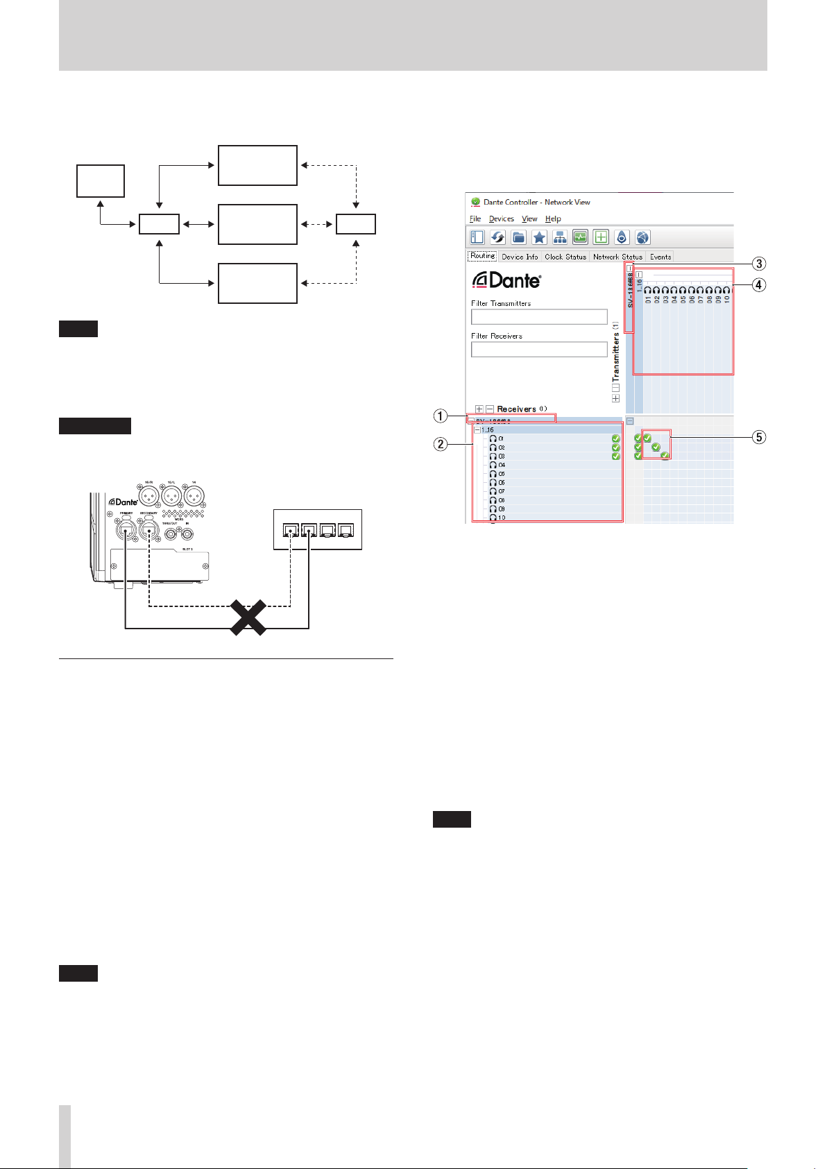
4 – Mixer configuration and settings
Redundant connection example
Primary Secondary
Sonicview 16 /
PC
HUB
NOTE
Settings for switched (daisy chain) and redundant
connections do not change automatically. Tap Menu Screen
> Rear Panel Setup > Dante Setup to open the Dante SETUP
Screen, or change the settings on the Dante Controller
Network Config screen.
ATTENTION
The primary and secondary networks cannot be connected
on the same LAN (VLAN).
Sonicview 24
Dante
device
Dante
device
Audio routing settings
When Dante Controller is launched, the Network View screen
shown below will open.
On this screen, you can set and monitor conditions related to
the Dante network.
HUB
Hub
Secondary
Primary
Using Dante Controller
Dante Controller overview
This unit uses the Dante Controller application, which is
available at the Audinate website, to connect with other devices
that support Dante.
Download the latest version of the Dante Controller application
and an operation manual from the Audinate website.
Audinate download page
https://www.audinate.com/products/software/dantecontroller
Make at least the following settings using a computer that has
Dante Controller installed.
o Set the audio routing.
o Adjust the sampling frequency and bit depth of each Dante
device.
1 Receiving device name
This is the name of a receiving device on the Dante network.
2 Receiving device channels
These are the names of the channels of the receiving device
on the Dante network.
3 Transmitting device name
This is the name of a transmitting device on the Dante
network.
4 Transmitting device channels
These are the names of the channels of the transmitting
device on the Dante network.
5 Audio routing
Route the audio channels of the transmitting and receiving
devices that you want to connect here.
Click the intersection of the channels you want to connect on
the matrix to connect them.
NOTE
While pressing the computer keyboard Ctrl key, click the “-” at
the intersection of device names to connect all connectable
channels at once.
NOTE
Settings made using Dante Controller are stored in the builtin memory of each Dante device.
Unless settings are modified, connections will not
change even if Dante Controller is quit or the computer is
disconnected from the Dante network.
86 TASCAM Sonicview 16/Sonicview 24 V1.1.0

4 – Mixer configuration and settings
Changing sampling frequencies and bit
depths with Dante Controller
Double-click a device name on the Network View screen to open
the Device View screen.
On this screen, you can set and monitor conditions related to
devices on the Dante network.
Click the Device Config tab to open the page where you can
change the sampling frequency, bit rate and other settings of
the device selected in 1 shown in the illustration below.
1 Device name
This is the name of the device that can have its settings
changed in the current Device View.
2 Change device name
Edit the device name.
3 Sampling frequency
Set the sampling frequency.
NOTE
This can also be set on the unit.
4 Bit depth
Set the bit depth.
5 Latency setting
Set the latency.
Use the following guidelines to change the latency setting.
Selectable latency
value
250usec
500usec
1msec
2msec
5msec
ATTENTION
i This unit is not compatible with 100Mbps Ethernet switching
hubs. Always use switching hubs that are compatible with
Gigabit Ethernet.
i Changing the name of a device will clear audio routing
settings. For this reason, we recommend changing device
names to names that are easy to identify before setting audio
routings.
i Depending on network connection conditions, setting
the latency to a value higher than the guideline might be
necessary.
NOTE
i This can also be set on the unit.
i When using a switched (daisy chain) connection, which does
not use a switching hub, set the latency according to the
number of Dante devices that signals pass-through as shown
below.
Connected network setup
guideline
The transmission route from the
transmitting device to the receiving
device passes through 1 gigabit
switching hub.
The transmission route from the
transmitting device to the receiving
device passes through 5 gigabit
switching hub.
The transmission route from the
transmitting device to the receiving
device passes through 10 gigabit
switching hub.
The transmission speed of the
transmitting device is 100 Mbps.
Use this maximum selectable latency
value when creating a large-scale
network.
Switched (daisy chain) connection example
Passes through 2 devices
Transmitting
device
Passes through 1 devices
Transmitting
device
NOTE
The Dante module in this unit and IF-DA64 Dante cards (sold
separately) have built-in switching hubs.
For this reason, when counting Dante devices, count this unit
and IF-DA64 cards as two devices each.
TASCAM Sonicview 16/Sonicview 24 V1.1.0 87
1st
device
1st
device
2nd
device
Receiving
device
Receiving
device

4 – Mixer configuration and settings
SLOT SETUP screen
Make settings and view information for expansion cards
installed in SLOT 1 and SLOT 2 on this screen.
Tap Menu Screen > Rear Panel Setup > Slot Setup to open this
screen.
1 SLOT 1
This shows the name of the expansion card installed in SLOT
1 on the rear panel.
2 SLOT 2
This shows the name of the expansion card installed in SLOT
2 on the rear panel.
3 SLOT 1 parameters
This shows the parameters of the expansion card installed in
SLOT 1 on the rear panel.
4 SLOT 2 parameters
This shows the parameters of the expansion card installed in
SLOT 2 on the rear panel.
NOTE
“No Card” will appear if no card has been installed in SLOT 1
or SLOT 2.
Precautions when using an IF-DA64
The Dante module built into this unit, an
card
installed in a SLOT and the unit’s master clock must be
synchronized. Do this as follows.
o When the unit’s master clock is not Dante (INT, WORD, etc.)
Use Dante Controller to set the Sync to External setting to
“ON” for both the built-in Dante module and the IF-DA64.
Use Dante Controller to set the Preferred Leader setting to
“ON” for either one of them. (We recommend using the builtin Dante module.)
Master clock: Not Dante (WORD, etc.)
Built-in Dante module
Sync to External: ON
Preferred Leader: ON
o When the unit’s master clock is Dante
Use Dante Controller to set the Sync to External setting to
“ON” for the IF-DA64.
Use Dante Controller to set the Preferred Leader setting
to “ON” for a Dante module other than an IF-DA64. (We
recommend using the built-in Dante module.)
Master clock: Dante
IF-DA64 Dante
IF-DA64
Sync to External: ON
Preferred Leader: OFF
When IF-DA64 installed
1 STATUS
This shows the operation status of the installed IF-DA64.
STATUS Meaning
Available
Unavailable
The installed IF-DA64 is operating
normally.
The installed IF-DA64 is not operating
normally.
Built-in Dante module
Sync to External: OFF
Preferred Leader: ON
IF-DA64
Sync to External: ON
Preferred Leader: OFF
88 TASCAM Sonicview 16/Sonicview 24 V1.1.0

4 – Mixer configuration and settings
When IF-AE16 installed
1 SRC ON/OFF buttons
These turn the SRC (sample rate converter) ON (default) and
OFF for each signal line.
The selected buttons will be highlighted.
When IF-MA64/EX or IF-MA64/BN installed
5 2×Fs MADI OUTPUT FRAME buttons
These set the MADI output signal frame type when the unit's
sampling frequency is 96 kHz.
Options: 48K Feame, 96K Frame (default)
The selected button will be highlighted.
ATTENTION
A MADI signal with a 96kHz sampling frequency and 48K
Frame type cannot be distinguished from a MADI signal with
a 48kHz sampling frequency.
For this reason, a 48K Frame MADI input signal that does not
match the sampling frequency of the receiving device cannot
be received as proper audio data.
When using a 48K Frame MADI signal, always match the
sampling frequencies of the signal sending and receiving
devices.
NOTE
The signal from the IF-MA64/EX MADI COAXIAL IN connector
is output through its MADI COAXIAL THRU connector
whether the unit is on or off.
When the unit is turned on/off, however, the signal output
from the MADI COAXIAL THRU connector will be momentarily
disrupted.
For this reason, time turning the unit on/off carefully when
the signal output from the MADI COAXIAL THRU connector is
being used by a connected device.
6 MADI COAXIAL EQUALIZER buttons
Set the equalizer for MADI COAXIAL input signals.
When an IF-MA64/EX or IF-MA64/BN is connected and a
low-voltage MADI COAXIAL signal source or long BNC cable is
being used, proper reception is not possible sometimes.
In this case, try setting MADI COAXIAL EQUALIZER to OFF.
Options: OFF, ON (default)
The selected button will be highlighted.
1 MADI INPUT STATUS
This shows the channel mode/frame frequency of the MADI
input signal.
“No signal” will appear if there is no input signal.
2 MADI INPUT FRAME
This shows the MADI input signal frame type (48K Frame/96K
Frame).
“No signal” will appear if there is no input signal.
3 MADI INPUT SELECT buttons (IF-MA64/EX only)
Set the input connector used.
Options: COAXIAL, OPTICAL (default)
The selected button will be highlighted.
4 MADI OUTPUT CH MODE buttons
Set the output channel mode.
Options: 56ch/28ch, 64ch/32ch (default)
The selected button will be highlighted.
NOTE
i Left of /: 1×Fs channel mode
i Right of /: 2×Fs channel mode
When IF-AN16/OUT installed
1 OUTPUT ATTENUATOR knobs
These adjust the output levels.
Range: -14.0 dB – 0.0 dB (default)
When the selection frame is shown, use the corresponding
LCD knobs to adjust the values.
NOTE
The IF-AN16/OUT will always operate at 96 kHz even when
synchronized to a master clock that is 48 kHz.
TASCAM Sonicview 16/Sonicview 24 V1.1.0 89

4 – Mixer configuration and settings
Network Setup screen
Use this screen to make network settings primarily for the
purpose of remote control of this unit using the dedicated
TASCAM Sonicview Control application.
For details about the TASCAM Sonicview Control application, see
its manual. You can download the application manual from the
TEAC Global Site (https://teac-global.com/).
Tap Menu Screen > Rear Panel Setup > Network Setup to open
this screen.
1 Network status
This shows the network status of the unit.
Item Content
MAC Address This shows the unit's MAC address.
IP Address This shows the unit's IP address.
2 IP SETUP
Set the IP address setting mode.
Options: AUTO (default), STATIC
3 IP Address/Subnet Mask/Default Gateway
o This shows the IP Address, Subnet Mask and Default
Gateway of the unit when IP SETUP is “STATIC”.
default: 0.0.0.0
o This will be gray when IP SETUP is “AUTO”.
o Tap the address fields to open the IP Address, Subnet
Mask and Default Gateway screens.
4 Password
Set the password to use when connecting to this unit
through a network.
Tap the Change button to open the Change password screen.
The password can have up to 16 characters.
Model Default password
Sonicview 16 Sonicview16
Sonicview 24 Sonicview24
The combination of characters input can be changed
depending on the status of the Caps lock and Shift keyboard
buttons on the Change password screen. See “Changing the
keyboard keys” on page 162 for details about changing the
keyboard.
ATTENTION
The following symbols and punctuation marks cannot be
input.
¥ / : * ? " < > |
NOTE
A USB keyboard that is connected to the top panel USB port
can also be used to input and edit characters.
IP ADDRESS setting screen
See “IP Address/Subnet Mask/Default Gateway setting
procedures” on page 91 for details about how to use
these setting screens.
90 TASCAM Sonicview 16/Sonicview 24 V1.1.0

4 – Mixer configuration and settings
5 Machine Name
The name of the unit on the network can be set so remote
applications can distinguish it from other Sonicview units
when multiple ones are on the network.
Tap this area to open the Machine name screen.
The machine name can have up to 16 characters.
Model Default machine name
Sonicview 16 Sonicview16
Sonicview 24 Sonicview24
The combination of characters input can be changed
depending on the status of the Caps lock and Shift keyboard
buttons on the Machine name screen. See “Changing the
keyboard keys” on page 162 for details about changing the
keyboard.
IP Address/Subnet Mask/Default Gateway
setting procedures
The IP address is set to “192.168.1.1” as an example in this
explanation.
1. Tap the IP Address, Subnet Mask and Default Gateway fields
to open their setting screens.
2. Tap the number buttons to input setting values.
ATTENTION
The following symbols and punctuation marks cannot be
input.
¥ / : * ? " < > |
NOTE
A USB keyboard that is connected to the top panel USB port
can also be used to input and edit characters.
3. Tap “ . ” to move the cursor to the next field.
To change a setting, tap it to move the cursor to that field.
4. Repeat steps 2–3 as necessary to input setting values in
each field.
TASCAM Sonicview 16/Sonicview 24 V1.1.0 91
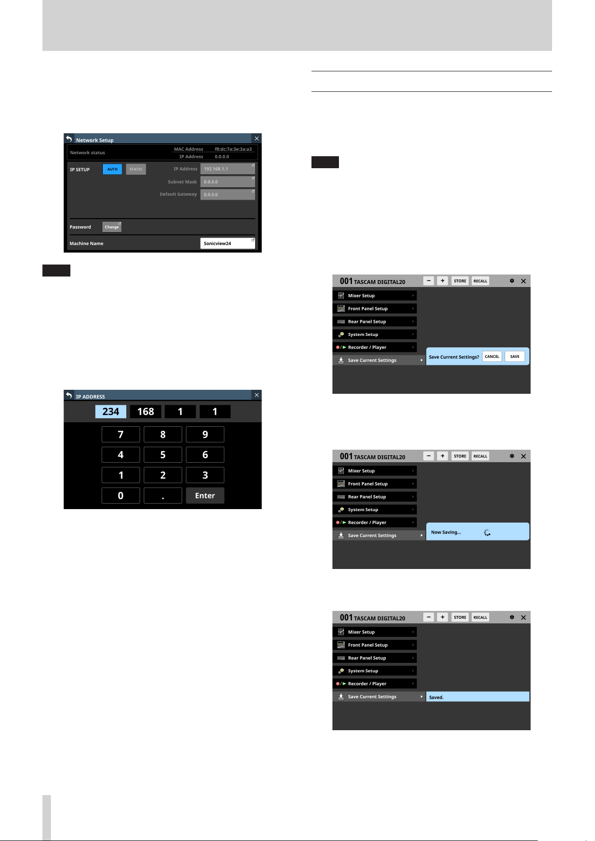
4 – Mixer configuration and settings
5. Tap the Enter button to confirm the input and return to the
Network Setup Screen.
Changed settings will be reflected in the IP Address, Subnet
Mask and Default Gateway fields of the Network Setup
Screen.
NOTE
i Each input field has three digits. When inputting values with
less than three digits, inputting “0” first is not necessary.
i After this screen opens, the first field will be highlighted.
i When a field is highlighted, tapping a number button will
input that number, replacing the value previously in the field.
After this, input numbers as on a calculator.
i If a fourth digit is entered, the first digit entered will be
removed. For example, if “1234” was entered, “1” will be
removed.
Saving the current settings
The settings of the unit are saved to the internal memory at least
once every minute.
To be certain that the unit settings are saved in the internal
memory before turning the power off, use the Save Current
Settings function explained below.
NOTE
After saving All System Data or storing snapshot, EQ and
other library settings data, settings have already been output
to the memory, so these operations are not necessary before
turning the power off.
1. Press the MENU key to open the Menu Screen.
2. On the Menu Screen, show the Save Current Settings item.
3. Tap the Save Current Settings item to open a saving
confirmation message to the right of the menu list.
4. Tap the SAVE button to save the unit’s settings to its internal
memory.
o The message shown below will appear while saving.
o “Saved.” will momentarily appear after saving completes
and then this message will disappear.
92 TASCAM Sonicview 16/Sonicview 24 V1.1.0

4 – Mixer configuration and settings
TASCAM Sonicview 16/Sonicview 24 V1.1.0 93

5 – Routing
This chapter explains mixer input and output routing.
Input routing
Use the following screen for input routing.
CH 1–40/ST IN 1–2 MODULE (OVERVIEW)
Screens
Tap the MODULE NAME area on the Home Screen to open this
screen.
CH 1–40 modules
o If a Dante port that has a mounted SB-16D assigned is
selected, “SB #[ID] [port number]” will be shown.
If it is a virtually-mounted SB-16D, will appear.
o Tap this button to open the INPUT SOURCE SELECT Screen
where input sources can be selected. (See “INPUT SOURCE
SELECT screen” on page 102.)
CH 1–40/ST IN 1–2 MODULE (INPUT) Screens
Tap the INPUT area on the Home Screen of a CH 1–40/ST IN 1–2
module when the selection frame is shown to open this screen.
ST IN 1–2 modules
1 INPUT button
o This shows the name of the input source assigned to the
selected module.
o If the module is stereo, input source names will appear
split left and right and abbreviated as follows.
Module name
shown
ANALOG AN
Dante DA
SLOT 1 S1
SLOT 2 S2
USB IN USB
ST IN 1 ST1
ST IN 2 ST2
PLAYER PL
SB-16D SB
Stereo module name
shown
CH 1–40 modules
ST IN 1–2 modules
1 LOCK/UNLOCK button
o This button locks/unlocks routing setting change
operations for the unit. This is always locked at the time of
start up.
o When set to “LOCK”, tapping INPUT SOURCE (2) and OSC
(3) buttons will not change settings. Furthermore, the
8ch BLOCK, 16ch BLOCK, 24ch BLOCK and BATCH SETUP
buttons will also be disabled. However, tapping the Others
button and switching to the INPUT SOURCE SELECT
Screen is possible.
o When set to “LOCK”, tap this button to open a confirmation
message. Tap the UNLOCK button to close the message
and set it to “UNLOCK”. Tapping the CANCEL button on
the confirmation message will close it and maintain the
locked state.
94 TASCAM Sonicview 16/Sonicview 24 V1.1.0

5 – Routing
o If the module is stereo and input sources that are not
left-right adjacent are selected, input source names will
appear split left and right and abbreviated as follows on
the Others button.
o Tap this button when set to “UNLOCK” to switch it to
“LOCK”.
NOTE
The LOCK/UNLOCK button (1) setting is shared by the
following routing setting screens.
i MODULE (INPUT) Screen
i MODULE (OUTPUT) Screen
i INPUT SOURCE SELECT Screen
i OUTPUT PORT SELECT Screen
i DIRECT OUT PORT SELECT Screen
i INSERT SEND PORT SELECT Screen
i INSERT RETURN PORT SELECT Screen
2 INPUT SOURCE buttons
o When the LOCK/UNLOCK button (1) is set to “UNLOCK”,
tap input sources to select them for the selected module.
Only the one button for the selected input source will be
highlighted.
o Buttons for Dante ports that have mounted SB-16Ds
assigned will be shown as “SB #[ID] [port number]”.
If it is a virtually-mounted SB-16D, will appear to the top
right.
Module name
shown
ANALOG AN
Dante DA
SLOT 1 S1
SLOT 2 S2
USB IN USB
ST IN 1 ST1
ST IN 2 ST2
PLAYER PL
o Tap the Others button to open the INPUT SOURCE SELECT
Screen where input sources not shown on this screen can
be selected. (See “INPUT SOURCE SELECT screen” on page
102.)
NOTE
Input sources for multiple channels can also be set at the
same time. (See “Setting input sources for multiple channels
at the same time in blocks” on page 96.) (See “Setting
inputs sources for multiple channels at the same time in
batches” on page 96.)
Stereo module name
shown
3 OSC button
o When the LOCK/UNLOCK button (1) is set to “UNLOCK”,
tap this button to turn internal oscillator signal input on or
off (default).
o When turned on, the input for the selected module will
switch to the signal from the internal oscillator. When
on, this button will appear highlighted, and the INPUT
SOURCE selection (2) button area will be dimmed.
o When this is turned off, the input source selected for
the selected module using the INPUT SOURCE selection
buttons will be reactivated.
o Assigned buttons for Dante ports that have virtually-
mounted SB-16Ds will be highlighted yellow.
o If the selected input source is not shown elsewhere on this
screen, it will be shown on the Others button.
NOTE
To turn the internal oscillator on/off, adjust its level and
make other settings for it, tap the icon above and to the
left of the OSC button and switch to the MONITOR SETUP
(MONITOR/SOLO) Screen. (See “Making talkback and built-in
oscillator settings” on page 57.)
TASCAM Sonicview 16/Sonicview 24 V1.1.0 95

5 – Routing
Setting input sources for multiple channels at the same time in blocks
1. When the LOCK/UNLOCK button (1) is set to “UNLOCK”, tap
the 8ch BLOCK, 16ch BLOCK (Sonicview 16) or 24ch BLOCK
(Sonicview 24) button on the MODULE (INPUT) Screen to
open a window where multiple input sources can be set at
the same time.
4. Tap the OK button to set multiple input sources at the same
time.
This will return to the MODULE (INPUT) Screen where the
INPUT SOURCE selection button will show the selected
input source.
NOTE
i When the LOCK/UNLOCK button is set to “LOCK”, the 8ch
BLOCK, 16ch BLOCK and 24ch BLOCK buttons are disabled.
i If routing operation is set to “LOCK” on another touchscreen
while a multiple setting window is open, it will close
automatically.
Setting inputs sources for multiple channels at the same time in batches
1. When the LOCK/UNLOCK button (1) is set to “UNLOCK”, tap
the BATCH SETUP button on the MODULE (INPUT) Screen to
open a BATCH SETUP window where multiple input sources
can be set at the same time.
2. Swipe the options up and down to select the input sources.
Selections can also be changed by turning LCD Knob 3 (for
the 8ch BLOCK) or LCD knob 4 (for the 16ch/24ch BLOCK).
3. Tap the APPLY button to open a setting confirmation
window.
2. Swipe the options up and down to select the input sources
and the modules they will be assigned to.
Selections can also be changed by turning the LCD Knobs
2–6 with the same colors.
3. Tap the APPLY button to open a setting confirmation
window.
4. Tap the OK button to set multiple input sources at the same
time.
This will close the BATCH SETUP window, and the INPUT
SOURCE selection button will show the selected input
source.
NOTE
i When the LOCK/UNLOCK button is set to “LOCK”, the BATCH
SETUP button is disabled.
i If routing operation is set to “LOCK” on another touchscreen
while a multiple setting window is open, it will close
automatically.
96 TASCAM Sonicview 16/Sonicview 24 V1.1.0

5 – Routing
Direct out signal output routing
The CH 1–40 modules have direct out functions.
Set direct out signal output routing on the MODULE (OVERVIEW)
Screen for CH 1–40 modules.
Tap the MODULE NAME area on the Home Screen to open this
screen.
CH 1–40 modules
1 DIRECT OUT button
Tap this button to turn DIRECT OUT ON (default) or OFF.
When ON, the signal will be output directly from this point,
and this button and the DIRECT OUT TRIM knob will be
highlighted.
3 OUTPUT button
o This shows the name of the output port that the DIRECT
OUT signal is assigned to. If it has been assigned to
multiple output ports, “…” will appear to the bottom right
of the button.
o If the module is stereo, output port names will appear
split left and right and abbreviated as follows.
Module name
shown
ANALOG AN
Dante DA
SLOT 1 S1
SLOT 2 S2
USB OUT USB
o If a Dante port that has a mounted SB-16D assigned is
selected, “SB #[ID] [port number]” will be shown.
Stereo module name
shown
NOTE
The DIRECT OUT POINT for CH 1–40 modules can also be
changed as explained in “CH 1–40 CONFIG page” on page
40.
2 DIRECT OUT TRIM knob
Use this to adjust the DIRECT OUT output signal level.
Range: -20 dB – +20 dB (default: 0 dB)
Turn LCD knob 2/4/5/7 (lit blue) to adjust it.
NOTE
The knob used for this operation depends on DIRECT OUT
POINT and DELAY POINT settings.
If it is a virtually-mounted SB-16D, will appear.
o Tap this button to open the DIRECT OUT PORT SELECT
Screen where DIRECT OUT output ports can be selected.
(See “DIRECT OUT PORT SELECT screen” on page 104.)
TASCAM Sonicview 16/Sonicview 24 V1.1.0 97
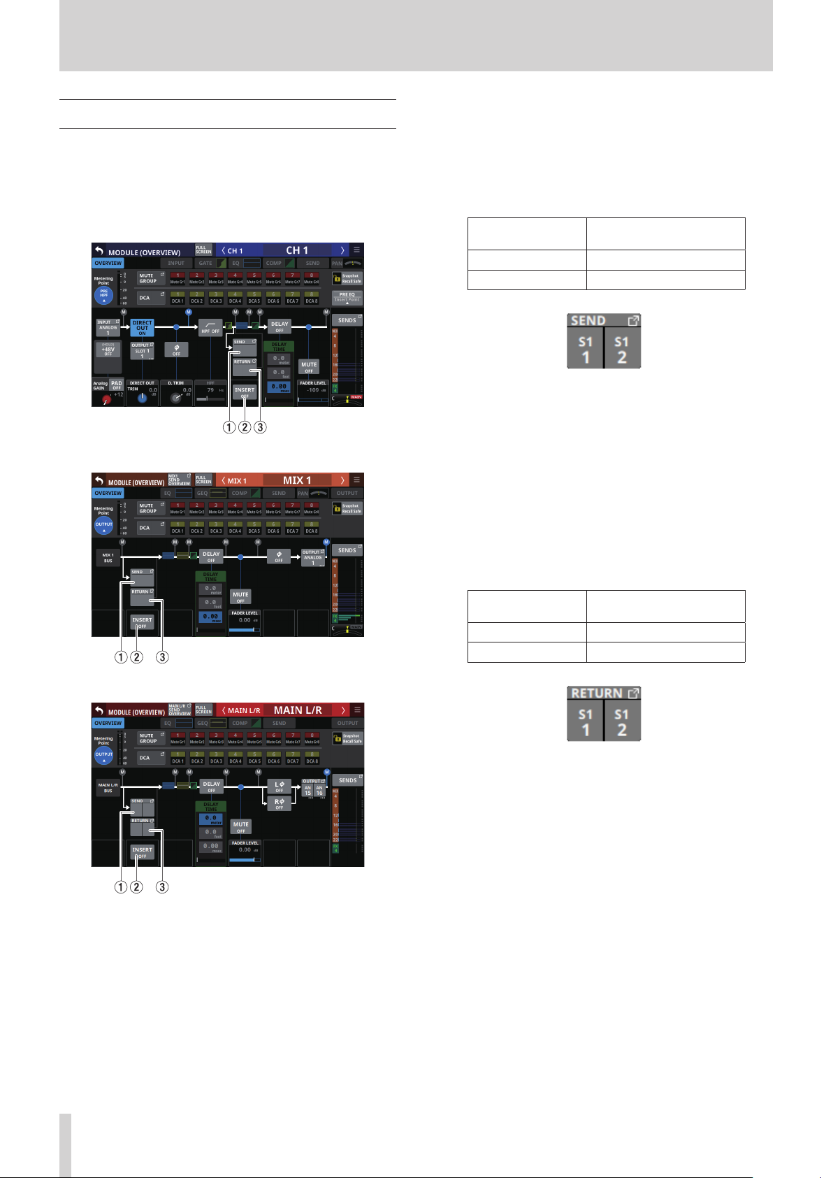
5 – Routing
Insert input and output routing
The CH 1–40, MIX1–22 and MAIN L/R Master modules have
insert functions.
Set insert input and output routing on the MODULE (OVERVIEW)
Screen of these modules.
Tap the MODULE NAME area on the Home Screen to open this
screen.
CH 1–40 modules
1 SEND button
o This shows the name of the output port that the INSERT
SEND signal is assigned to. If it has been assigned to
multiple output ports, “…” will appear to the bottom right
of the button.
o If the module is stereo, output port names will appear
split left and right and abbreviated as follows.
Module name
shown
SLOT 1 S1
SLOT 2 S2
o Tap this button to open the INSERT SEND PORT SELECT
Screen where INSERT SEND signal output ports can be
selected. (See “INSERT SEND PORT SELECT screen” on page
106.)
Stereo module name
shown
2 INSERT button
Tap this button to turn INSERT ON or OFF.(default).
When this is ON, the button will appear highlighted.
3 RETURN button
o This shows the name of the input port that is assigned for
the INSERT RETURN signal.
o If the module is stereo, input port names will appear split
left and right and abbreviated as follows.
MIX 1–22 modules
MAIN L/R Master module
Module name
shown
SLOT 1 S1
SLOT 2 S2
o Tap this button to open the INSERT RETURN PORT SELECT
Screen where INSERT RETURN signal input ports can be
selected. (See “INSERT RETURN PORT SELECT screen” on
page 107.)
Stereo module name
shown
98 TASCAM Sonicview 16/Sonicview 24 V1.1.0

5 – Routing
Output routing
Use the following screens for output routing.
MIX 1–22 and MAIN L/R Master MODULE
(OVERVIEW) Screens
Tap the MODULE NAME area on the Home Screen to open this
screen.
MIX 1–22 modules
1 OUTPUT button
o This shows the name of the output port that the output
signal of the selected module is assigned to. If it has been
assigned to multiple output ports, “…” will appear to the
bottom right of the button.
o If the module is stereo, output port names will appear
split left and right and abbreviated as follows.
Module name
shown
ANALOG AN
Dante DA
SLOT 1 S1
SLOT 2 S2
USB OUT USB
o If a Dante port that has a mounted SB-16D assigned is
selected, “SB #[ID] [port number]” will be shown.
Stereo module name
shown
MAIN L/R Master module
If it is a virtually-mounted SB-16D, will appear.
o Tap this button to open the OUTPUT PORT SELECT Screen
where output ports can be selected. (See “OUTPUT PORT
SELECT screen” on page 108.)
TASCAM Sonicview 16/Sonicview 24 V1.1.0 99

5 – Routing
MIX 1–22 and MAIN L/R Master MODULE
(OUTPUT) Screens
Tap the OUTPUT area at the top of the Home Screen of a MIX
1–22 or MAIN L/R Master module to open this screen.
MIX 1–22 modules
NOTE
The LOCK/UNLOCK button (1) setting is shared by the
following routing setting screens.
i MODULE (INPUT) Screen
i MODULE (OUTPUT) Screen
i INPUT SOURCE SELECT Screen
i OUTPUT PORT SELECT Screen
i DIRECT OUT PORT SELECT Screen
i INSERT SEND PORT SELECT Screen
i INSERT RETURN PORT SELECT Screen
2 OUTPUT PORT selection buttons
o When the LOCK/UNLOCK button (1) is set to “UNLOCK”,
tap signal output ports to select them for the selected
module. The selected output port button will be
highlighted light blue. If a selection button that already
has another output signal assigned to it (shown by *) is
tapped, a setting confirmation window will open. Tap the
OK button to change the setting and close the window.
Tap the CANCEL button to close the window without
changing the setting.
MAIN L/R Master module
1 LOCK/UNLOCK button
o This button locks/unlocks routing setting change
operations for the unit. This is always locked at the time of
start up.
o When set to “LOCK”, tapping the OUTPUT PORT selection
button (2) will not change settings. Furthermore, the
8ch BLOCK, 16ch BLOCK and BATCH SETUP buttons will
also be disabled. However, tapping the Others button and
switching to the OUTPUT PORT SELECT Screen is possible.
o When set to “LOCK”, tap this button to open a confirmation
message. Tap the UNLOCK button to close the message
and set it to “UNLOCK”. Tapping the CANCEL button on
the confirmation message will close it and maintain the
locked state.
o If a Dante port that has a mounted SB-16D assigned is
selected, “SB #[ID] [port number]” will be shown.
If it is a virtually-mounted SB-16D, will appear.
o Assigned buttons for Dante ports that have virtually-
mounted SB-16Ds will be highlighted yellow.
o Tap this button when set to “UNLOCK” to switch it to
“LOCK”.
100 TASCAM Sonicview 16/Sonicview 24 V1.1.0
o If the selected output port is not shown elsewhere on this
screen, the output port name will be shown on the Others
button.
 Loading...