

Page 1

Page 2
TABLE OF CONTENTS
Chapter 1: Introduction ...........................................
The RC-848 multi-function remote control unit is the
heart of a professional production system of digital and
analog audio and video tapes ; it has Accessory I and 2
connectors to control TASCAM analog machines, and a
standard RS-422 interface to control VTRs or others,
The RC-848 can control a maximum of 6 DAs or
synchronize a system of up to I6 DAs to sample
acc”mcy.
Chapter 2: Accessing the Menu Screens
Chapter 3: Features and Controls..
Chapter 4: Operations Guide..
4-1 Pre-Operating Procedures..
........................ 3 . I
................................ 4 - I
............................. 4 * I
4-2 Autolocator Functions ....................................
4-3 Variable Speed Playback
................................ 4 . 9
4-4 Entering a Track Delay Time..
4-5 Relative Reference Time Indication.. ...........
4-6 Punch-In Recording ......................................
More specifically the RC-84X’s capabilities include the
following :’
0 Menu names you use most frcquemly can be stored in
battery backup memory for instant access.
0 Battery backup of the last menu screen displayed
before selecting another machine, allowing you to
directly return to that menu when selecting the
corresponding machine again. This is also true of the
LOCATE TIME display.
0 Park position, this helps to eliminate a lag between a
tnaster and slave,
0 Crossfade time for click free punch-in recordings,
0 Instant reset of settings at multiple specific menus
0 Automatic offset entry
0 99.point autolocator functions
0 Jog/Shtmle wheel for locating specific points on audio
or video tapes at variable speeds
0 Split mode for punch-in recording referenced to a
video picmre.
SOFTWARE UPDATES
4-7 Copying Tracks (DA-3X Only).
4-8 Shuttle Monitor (DA-38 Only).
4-9 Selecting a TDIF Input Bit Length
(DA-38 Only). ..............................................
4-10 Enabling the Dither Function
(DA-38 Only) .............................................
Chapter 5 Synchronizing Multiple DAs
Chapter 6: Controlling Other Equipment
From ACCESSORY “1”.
6-1 Machines with a Parallel Port..
6-2 Event Output Facility (Available upon
Request Only). ................................................
Chapter? Controlling Other Equipment
From ACCESSORY
7-1 TASCAM Multitrack Cassette Recorders..
7-2 TASCAM Open-Reel Recorders..
7-3 TASCAM CD Players
7-4 Remote Functions Not Operational..
Chapter 8 : Controlling Other Equipment
....................................
From RS-422 Port
S-l Turning the Chase Mode of DA-60 MKII
On or Off .......................................................
.................... 4 . I4
................ 5 * I
....................... 6 - I
“2”. ........................ 7 . I
.............. 7 - 4
I - I
2 . .............. I
4 * 6
4 * ........................ 9
4 . IO
4 * 1 I
. .................... 4 I4
4. I5
4 . I5
6 - ........................ I
6 . I
.... 7 * I
7 . .................. 2
7 .
,X . ................................... I
.8 . I
-
3
-
8-2 Having a DA/VTR System Drop Into and
Many capabilities which were not available on earlier
models have been implemented on the RC-X4X ROM
version 4.00 and above. Information on all changes and
new feamres are included in this manual. If you wax to
make sure of the version number of your model,
simultaneously press REW, I FWD, and STOP after
switching on power to the RC-848 and before a
momentary illumination of all LEDs stops. The initial
screen will change to read 4.00 or a higher number. To go
back to the initial screen, switch the unit off, then powa
on again,
3 Using this manual
Before actually using the FlG348, skim through this
manual, so you will know where to look to when you
need answers.
Use of capital letters : Gcncrally, we use all upper case
type to designate a particular switch, indicator, control or
Out of Record (Function Available Upon
Request Only) ................................................
USING THE IX-s46 WITH THE SY-68
Chapter 9 : Accessing the Menu Screens
Chapter 10 : Striping Timecode..
.......................... IO * I
............. 9 - I
IO-I Preliminary.. ...............................................
IO-2 Recording Timecode on the DA-XE..
.......... IO s 1
IO-3 Timecodc Out Select ..................................
Chapter 11 : Syncing with DA-88 as Slave
I l-l Setting a Park Position..
Il.2 Synchronization ..........................................
I I-3 Offset sync
.................................................
.S . 1
IO. 1
IO . 2
......... 1 I - 1
I I . .............................. I
I I * I
11 *
I
1 I-4 Dubbing Audio and Timecodc
at One Time Between Two DA-X&.
Chapter 12 : Controlling a VTR..
Appendix : Pin Assignment Charts B
Dimensional Drawing
........................... 12 - I
11 . ........... 2
connector label, as in :“Press CLOCK until INT lights.”
Page 3
CHAPTEf32: ACCESSINGTHEMENUSC
3EENS
.------__-----_____-------__----------____
O”,” wile” we8 is hS,#,,d
Page 4
CHAPTER 2 : ACCESSING THE MENU SCREENS
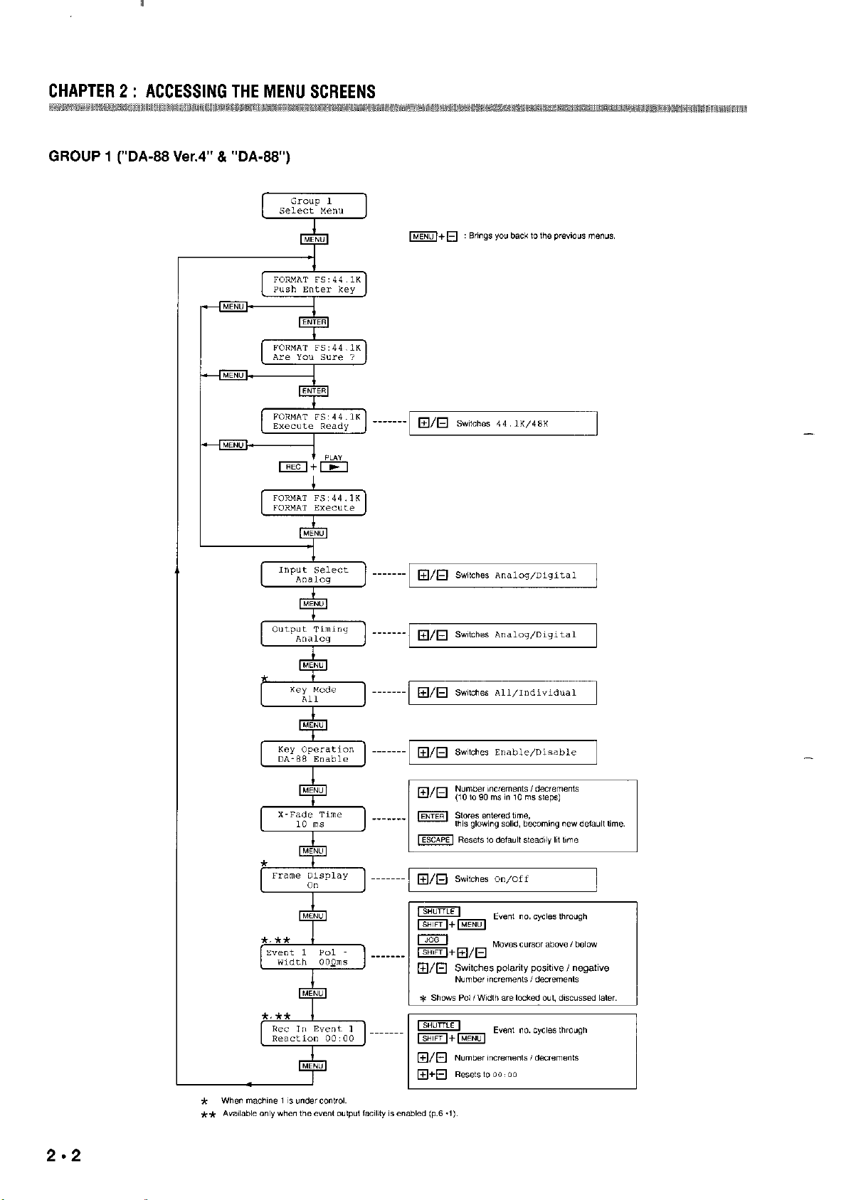
GROUP I (“DA-88 Ver.4” & “DA-88”)
2.2
Page 5
CHAPTER 2 : ACCESSING THE MENU SCREENS
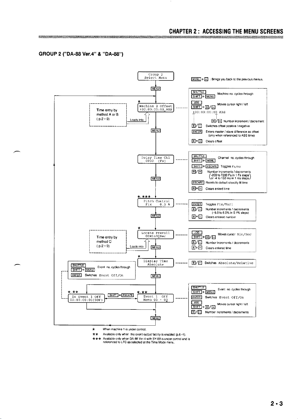
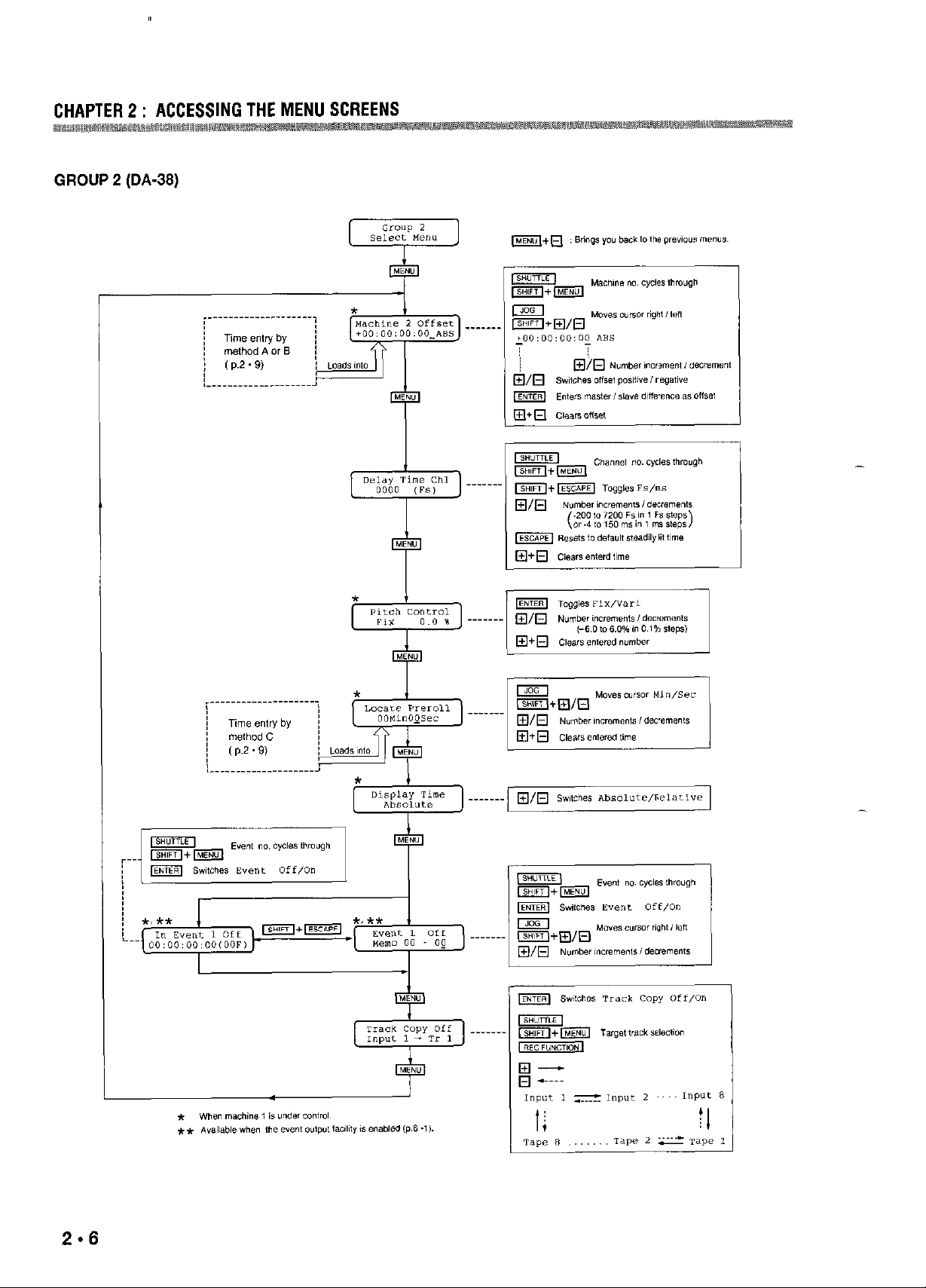
GROUP 2 rDA-88 Ver.4” 8 “DA-88”)
Page 6
CHAPTER 2 : ACCESSING THE MENU SCREENS
~rwm&!@am# ‘mmm~mm,~m
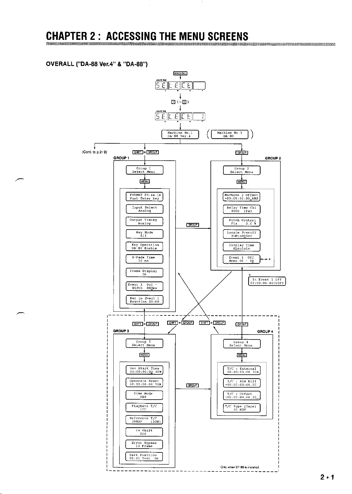
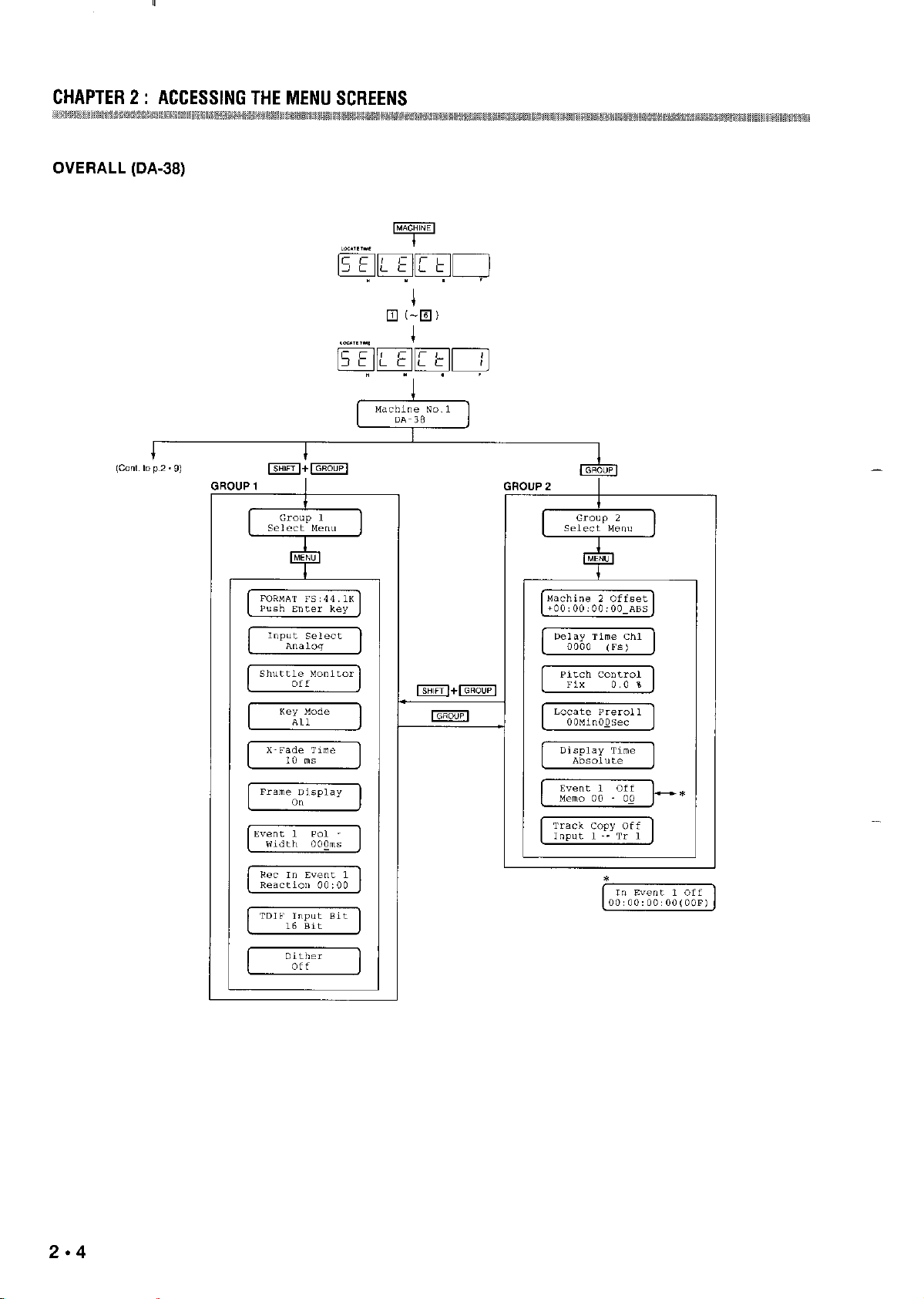
OVERALL (DA-38)
2.4
-
Page 7
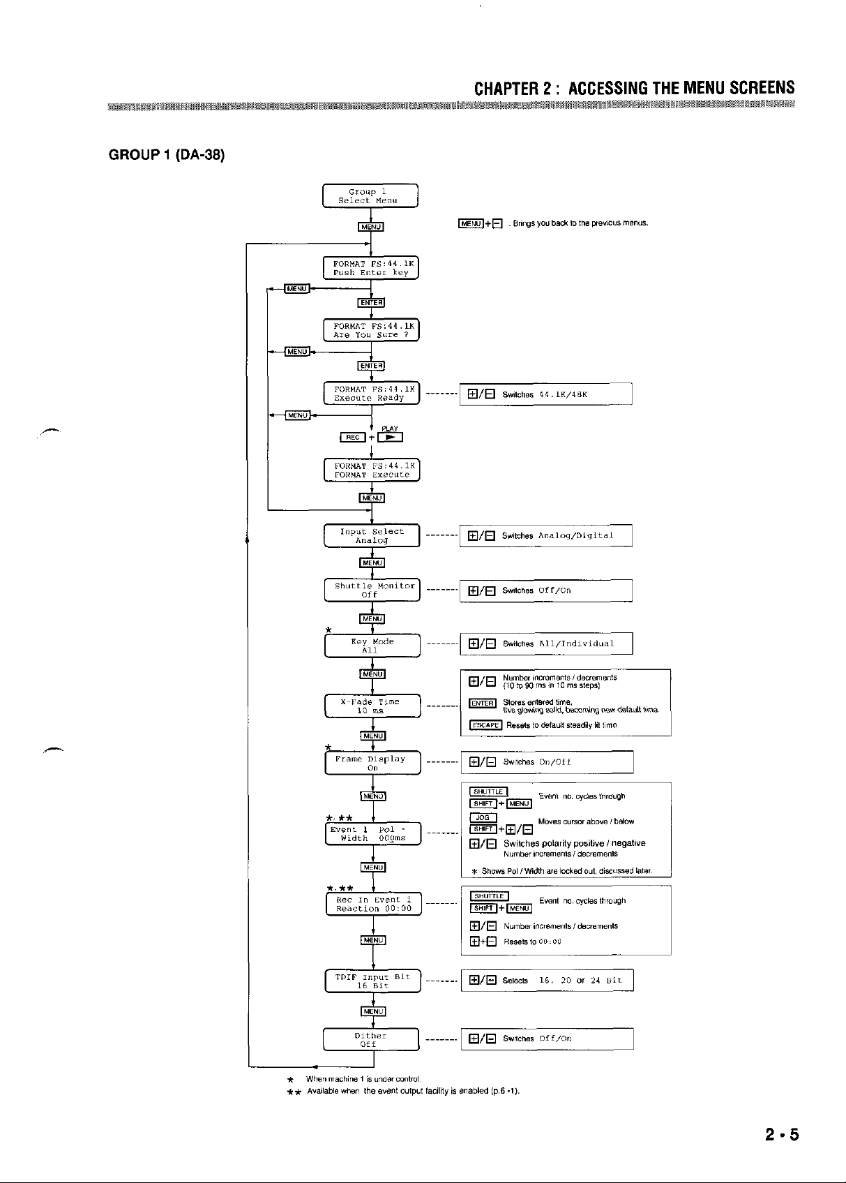
GROUP I (DA-38)
CHAPTER 2 : ACCESSING THE MENU SCREENS
km
g
Page 8
fu
.
m
Page 9
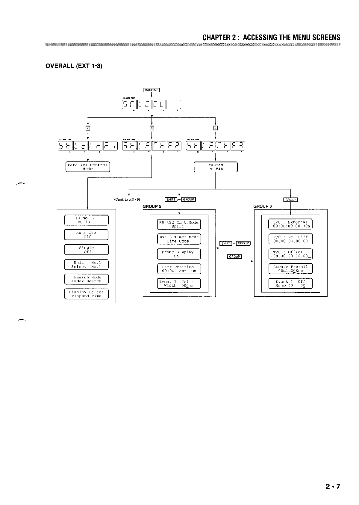
OVERALL (EXT 1-3)
CHAPTER 2 : ACCESSING THE MENU SCREENS
2.7
Page 10
CHAPTERZ: ACCESSINGTHEMENUSCREENS
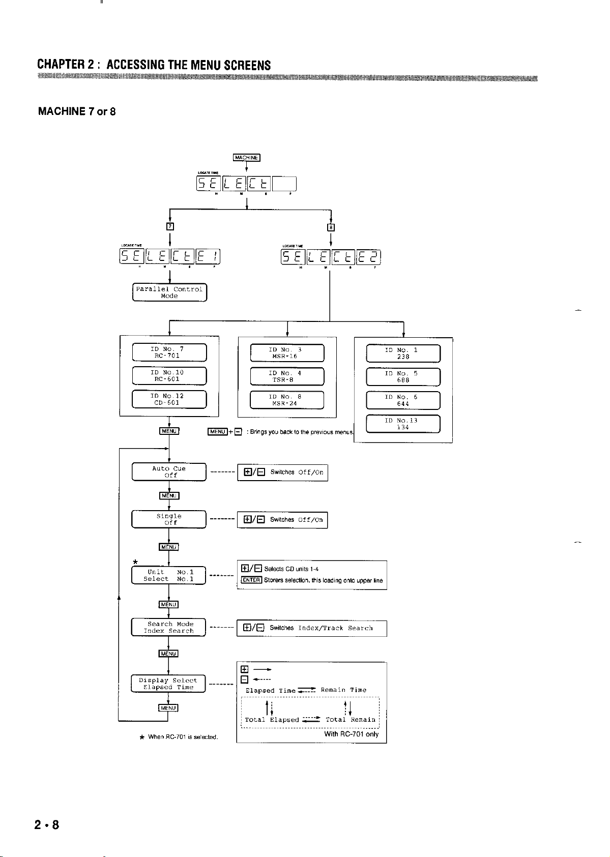
MACHINE 7 car 8
-
-
Page 11
mm
CHAPTER2: ACCESSINGTHEMENUSCREENS
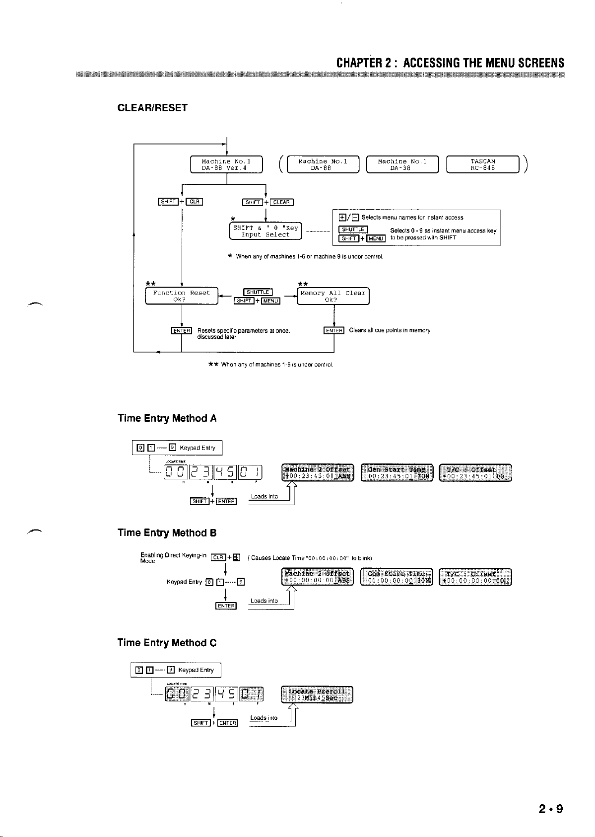
CLEAR/RESET
Time Entry Method A
Time Entry Method B
Time Entry Method C
2.9
Page 12
INSTANT ACCESS TO THE MENUS YOU USE
MOST FREQUENTLY
A maximum of I0 menus can be stored so you can
directly accas them by pressing SHIFT at the same time
as a numeric key (0.9) at the initial screen (which can
read “TASCAM RC-848”, “DA-88 Ver. 4”, “DA-88” or
“DA-38”, depending on yaw setup). This feature can be
used when any of machines 1-6, or machine 9, is under
colltrol,
If you are using the optional SY-88 Sync Board, we
suggest that yott also review the section with the
corrcspottdittg heading in Chapter 9,
You can select whatever me”” you want, as follows :
At the initial screen, press SHIFT + CLEAR (not
CLR). The screen will change to look like this :
Each time yo” press the plus (+) key, the menu names
will be displayed in order on the second line. To go
back to the previous men” name, press the minus (-)
key.
You are now selecting a nxnu that you can diretly
access when pressing SHIFT + 0 a.t the initial screen,
Rotate the SHUTTLE knob or press SHIFT + MENU,
The screen will change to look like this :
MENU SCREENS EXPLAINED
Those maw sxxns with no page reference are referred
to only in this section of the manual,
Menus which can be accessed only when you use the SY88 syttc board are explained in the section, USING THE
RC-848 WITH THE SY-88.
FORMAT FS
Selects sampling rates 44.1 and 48 kHz when fomxming
a tape (p.4.2).
hlput Select
Selects Digital/Analog as the source of the DA under
control (pp. 4 - 4 & 11 . 3).
Output Timing
Determines whether the DA-88 times its timecode output
to coincide with the analog output or with the digital
output (pp.5 .6 & 11 .3).
Key Mode
Determines, in a multiple DA systetn, whether the
following keys have effect only on a master DA or on all
slave DAs as well :
ALL SAFE/REC READY, ALL INPUT,
AUTO IWUT, and INSERT
When Individual is selected, they are effective only on a
machine under control (pp.5 ~4 & 5).
Then, select another men” by operating the + and keys, a menu that you will be able to access when
pressing SHIFT + I,
In the same manner, program other menus,
DIRECT RETURN TO MENUS
Each time you select another machine, the tnen” yen
were at is stored in a backup tnemory so you can
promptly go back to that menu when selecting the
machine again.
2.10
Key Operation
D&mines whether or not all controls on the DA under
control are locked wt.
X-Fade Time
For selection of a crossfade time for click-free dropping
into and out of record (p.4 - 1 I),
Frame Display
The frame dispIay is hidden when you select Off at this
menw This allows you to begin entering “seconds” when
entering on the numeric keypad. “00” is then
automatically entered in the frame section though it
remains hidden. This feature is NOT effective when
machine 7 or 8 is under control,
Page 13
Event (Poi and Width)
This me”” is where yo” select a polarity and pulse width
depending on event devices in “se. Event points can be
programed “t “n Event On/Off me”” (Group 2) (p.6 . I).
0 Menu Functions Available Only When DA-38 Is
Under Control
(Group I)
F&c in Event
Allows to overcome the response or reaction time
discrepancies between event devices yo” select at an In
Event menu (Group 2), so that they xe timed to st”rt
exactly “t an IN memory point yo” select “s ” Ret In
Shuttle Monitor
Used to activate or disable the corresponding function.
Remember, for the function to be actually available, both
the Insert and the Auto Input monitor functions must
additionally be activated (p.4. 14).
point for a recorder or recorders to drop into record (p.6 *
3.
TDIF input Bit
At this men” yo” can and have to select zi bit length for
Remember, this me”” is related to the In Event menu, but
has nothing to do with the Event On/Off men”.
-
0 Group 2
Mechine Offset
For entering offset values for individual machines 2-6
either manually on the numeric keypad or automatically
the DA-38 to send or receive digital data through its
TDIF-I !JO port (p.4. IS).
Dither
The re-quantization noise is or is not be ‘dithered’ (or
masked), as selected at this me”” (p.4 * 15).
(Group 2)
by pressing ENTER (p.5 - 3).
Machine Offset
Delay lime
For inserting delays in individual tracks I-8 (p.4 - 9).
Pitch ConVoi
For having ““y machine under control play at vari”bie
speeds. You c”” enter pitch changes before or during play
(pp.4 - 5 AL 9).
Allows the DA-38 to le”d or lag ” master within the
limits of +/-2 hours.
Track Copy
Tracks can be copied within one DA-38 or from tracks of
one DA-38 to tracks of another, “s controlled from this
“le”” (p.4 - 14).
Locate Preroii
This screen is where a preroll time is entered for the LOC
key to offer preroll “p to a point recalled from memory
0 Menu Functions Available Only When Machine
7 Or 8 Is Under Control
into the LOCATE TIME window (p.4 * 7). Not to be
-
confused with the “punch-in” preroli (p.4 * 13). Also
remember that this men” and the DA-38’s Autolocation
Preroli function are independent of each other.
Display Time
The TAPE TIME display shows elapsed time from ” “ser
selected point or from the beginning of the tape, as
Auto Cue
Switches the corresponding function on and off on CD-
601 or other TASCAM CD players.
Single
Determines whether the CD player under control only
plays ” single track or continues to play.
controlled from this men” screen (pp.4 - IO & I I).
Unit
Event (On and Off)
Allows yo” to switch individual events 1-5 on and off,
S&m CD-701~ when the RC-848 is used with the RC-
701.
and to select first and second shot points from memory
for each event (p.6 . I).
Search Mode
Determines whether the pickup of the CD player under
In Event
Used to select events (1.5) for them to be told to stwt
control skips directly to a specific index signal or to the
desired track (p.7 . 3).
“ser entered times before ” Ret In point, overcoming thus
the reaction or response time discrepancies between them
(p.6 . 2).
See also Ret /II Event (Group I).
Page 14
Display Select
The TAPE TIME display will read one of two track times
(Elapsed and Remain), a.s selected here, or when the RC-
701 is used, options are expanded to include two disc
times (Total Elapsed and Total Remain).
0 Others
These menus are accessible when any of machines I-6 is
under control.
Function Reset
Allows you to reset the following pxameters to theit
factory preset values at 0”ce :
CHAPTER 2 : ACCESSING THE MENU SCREENS
X-Fade Time (Group I), Machine Offset, Delay Time,
and Pitch Control (Group 2).
To do so, proceed as follows :
Press SHIFT + CLR (not CLEAR) at the initial screen, the
display will change to look like this :
Then, press ENTER. Or if you change your mind, you can
press ESCAPE ; you’ll then go back to the initial screen.
Memory All Clear
From this menu you can clear all cw points and a relative
reference point in memos at once, as follows :
Turn the SHUTTLE knob or press SHIFT + MENU at the
Function Reset menu above. The display will change to
look like this :
-
Then, press ENTER, All memories 00 to 99 for the DA
under control (any of machines 1-6) is cleared.
Or, if you change your mind, press ESCAPE. You’ll go
back to the initial screen.
If you turn the SHUTTLE knob or press SHIFT + MENU
(instead of pressing ENTER or ESCAPE), you’ll go back
to the Function Reset menu.
2.12
Page 15
CHAPTER3: FEATIJRESANDCONTROLS
7. Displays
MACHINE : Shows which machine is currently under
renlote colltrol.
“1” refers to the DA-XX which is ID-numbered “0” or to
the DA-38 which is ID-numbered “1” ; “2” to the DA-XX
which is ID-numbered “I” or to the DA-38 which 1s IDnumbered “2” ; and so on. “El” refers to ~II tmalog
machine connected to the remote’s 37.pin EXT l
(ACCESSORY 1) parallel port ; “E2” to a TASCAM
analog machine connected to the 15.pin EXT 2
(ACCESSORY 2) serial port ; and “E3” to a VTR
connected to the 9-pin EXT 3 (RS-422) port.
LOCK STATUS : When a slave machine is chasing the
master, the corresponding number blinks rapidly. It blinks
slowly when the slave is parked at the sane address as
the master. It glows solid when the slave starts playing
sy”c locked to the master.
LCD xrwn : Shows MENU-selectable options.
MEMORY POINT : Identifies the register into which XI
tape location is stored, or the register from which it is
recalled into the LOCATE TIME window,
IN and OUT will light when the respective keys we
pressed after STR and LOCAIE TIMES (which you ma.y
have entered with the numeric keys or have captured on
the fly with the v key) are stored into tnernory as the
punch-in and out points, If you hold the IN key and press
the OUT key, both the IN and OUT indicators will light
-
and the display will show the difference between the two
time addresses,
TAPE TIME : Shows elapsed time from the beginning of
the tape inserted in the machine currently under retnote
control, or time code numbers if available on that tape,
The TAPE TIME display a.” alternatively act as a tape
counter, showing elapsed time from an optionally set
reference point. See page 4.10, “Relative Reference Time
Indication.”
ABS and TC : ABS will light to show that the TAPE
TIME display is showing elapsed time from the
beginning of the tape. Or, TC will light when the display
is showing time code numbers as read off the tape
inserted to the machine currently under retnote control,
When both indicators (ABS and TC) are turned off, the
TAPE TIME display is showing a Relative Reference
time (p.4 - IO).
LOCATE TIME : Every tape location you capture on the
fly or enter with the nwneric keys is displayed in this
window. Tape locations recalled from memory are also
displayed here.
Each time you select another machine, the LOCATE
TIME reading at that tnotnettt is stored in a backup
memory. That reading is automatically read into the
LOCATE TIME window from tnemory when you select
the machine again.
8. GROUP switch
This brings you from one group of menus to another. For
more, see Chapter 2.
9. - and + keys
These keys have multiple uses, depending on menu : they
select options, enter numbers, tnove the cursor, etc.
PRE- and POSTroll times axe first entered with the
numeric keys into the LOCATE TIME window, then they
are stored into rnetnory when the respective keys are
pressed after STR (p.4.13).
START and END points tray either be captured on the fly
with the v key or be specified with the numeric keys,
Then they are stored into tnen~ory when the respective
keys are pressed after STR.
MEMORY NO. : Identifies the register into which you just
stored a tape location either captured on the fly with CUE
STORE or v, or entered with the numwic keys. For more
information, see page 4. 6. This display also shows the
register from which a tape location is currently recalled
into the LOCATE TIME window.
Pressing the plus key at the same time as the minus key at
the following menu screens :
Machine Offset, Delay Time, Pitch Control, Locate
Preroll, and Ret In Event
resets these parameters to the factory preset vahtes.
lO.ESCAPE key
This aborts operations if pressed when a warning is
displayed. The key is also used to store selections/
numbers at specific menus, as discussed later.
ii.SHlFT key
Holding this key and pressing the -/+ tnoves the cursor on
some specific tnenus such as the “Locate Preroll”
(p.4 - 7).
Page 16
CHAPTER3: FEATURESANDCONTROLS
12. MENU switch
Each time yo” press this switch, menu will switch in
seqwnce on the LCD screen. ‘Ilx menu will switch in
reverse order if yo” hold the MENU switch and press the
minus key.
13. ENTER key
Some menu-settings arc stored into memory only when
ENTER is finally pressed. The key is also used to select
men” options,
14. 4, l , and b indicators
“4” and “b” will light to show the direction in which
the t”pe is rolling “s yo” rotate the JOG/SHUTTLE wheel
to the left or right. “w” will light solid when yo” detach
the hand from the wheel and the tape stops moving, It
will flash when a local SHUTTLE wheel is operaed on
the DA currently under remote control and the remote
SHUTTLE is overridden.
15. JOG/SHUTTLE switch and the wheel
Pressing the switch allows yo” to “sc the inner JOG
wheel and the oar SHUTTLE knob for locating and
pinpointing ” specific point on the tape inscrtcd to the DA
currently “ndcr remote control at cominuously variable
speeds dctcmined by the “mo”nt of wheel/knob rotation
(from l/l6 up to 8 times nornul play speed),
If yo” dcmch yo”r hand from the knob/wheel, the tape
will stop, the machine going into Pause (Still) mode,
Activating the JOG/SHUTTLE switch during record also,
the transport will go into Pause (Still) mode,
When the switch is off, yo” c”n “se the JOG wheel m
move the c”rsor on so”~ specific mcn”s such “s the
“Machine Offset” and the “Event”, and the SHUTTLE
knob an be used to select machines or even& at those
“X”“S.
16. T key
When pressed, the TAPE TIME location “t that moment
is read into the LOCATE TIME window. The time
location thus captwcd can then be stored into any of the
99 memories, a specified by enwring ” MEMORY NO,
with the numeric keys,
TAPE TIMES read into the LOCATE TIME window with
the 7 key can also be stored into the IN, OUT, START,
and END registers by pressing the respcctivc keys.
Ii’. DOWN and UP keys
Time points c”raly recalled or read into the LOCATE
TIME window will dccrcment or increment by 1 frame
each time yo” press DOWN/UP, so yo” c”” “fine tune”
you punch-in/out points or other time points,
18. PRE, POST, IN, and OUT
PRE and POST : The desired pre- and postroIl times for
punch- in recording can be entered into the LOCATE
TIME window with the numeric keys. Then pressing
PRE/POST after STR skxcs that time into the PRE/POST
“lenlory.
Pressing PRE c”“ses the associated LED to st”rt blinking
and the LOCATE TIME display shows not the preroll
length but the point where the preroll will start from.
-
IN and OUT : You don’t need to go through the Rehearsal
setting procedure (p.4 * 12) if yo” know in advance the
exact time points where tracks should punch in and o”t of
record. You can enter these points with the numeric keys,
and press STR then IN/OUT to store them into memory
as the punch-in/out point. If yo” press IN or OUT law
on, the respective point is recalled from “xmory into the
LOCATE TIME display,
Tlx IN and OUT points can aIso be used as independent
autolocating points.
19. RHSL switch
Rehearsal is the first stage of an automatic insert or
punch- in recording. This key allows yo” to “preview” the
punch-in recording before it is actually committed to
tape. For ““xc see pages 4. I I & 12.
20. AUTO IN/OUT switch
Lets the punch-in recording be exec”k?d acually on upe
(p.4 * 13).
21. CLEAR key
This is used to disable the RHSL and AUTO IN/OUT
functions.
CLEAR is also used together with SHIFT to store men”
nxncs for instant access, previously discussed on p”ge
2.10.
If yo” cntcr wrong numbers into the LOCATE TIME
window, press the CLR key (item 32).
22. CHASE switch
When this is pressed, the LCD screen reads “CHASE,”
asking yo” which of machines 2-6 yo” want to slave to
machine 1. Then, for example, yo” c”n press 2 on the
keyp”d. Machine 2 will then be ““tolocated to the same
time point “s machine I.
Page 17
CHAPTER3: FEATURESANDCONTROLS
Enabling/Disabling Chase mode on all slave DAs at one
time, is explained in the section, Synchronizing Multiple
DAs.
For digital audio machines other than the DA to be
slaved, the optional SY-88 Sync Board needs be installed
into machine I.
23. MACHINE switch
When this is pressed, “Select” shows in the LOCATE
TIME window, and you can use the keypad to specify
which machine will be controlled from the remote. You
can select only one machine at a time.
24. TC REC switch
When a. DA-XX with SY-88 is under control, this switch
enables to record time code into the subcode area of the
tape loaded on that machine,
TC REC is also used to copy time code at the same time
as digital data from one DA to another DA. For more, see
pagesll.2&3.
25. REPEAT key
Enables the selected machine to play a loop determined
by the START and END memory points.
26. START and END keys
Pressing START after STR puts the current LOCATE
TIME (which you may have entered with the V key on
the fly or with the numeric keys) into memory as the start
point of play loop. Likewise, pressing END after STR
specifics the end point of your loop.
You can recall the start&d point into the LOCATE TIME
-
window by pressing START/END. Then you can “fine
tune” that time with the UP and DOWN keys, Pressing
LOC locates the tape to the start or end point (whichever
is currently displayed) ; so you can audition that point to
check for accumcy.
Pressing REPEAT lets the tape play over and over
between the START and END points,
27. AUTO PLAY key
Cases the machine currently under remote control to
start playing automatically each time it is autolocatcd to
any time point shown in the LOCATE TIME window.
26. Numeric keys
Unless you press STR or RCL before pressing numbers
on the keypad, your numbers will enter into the LOCATE
TIME window. Each time you enter one digit, the
previously cntcred digits will shift to the left.
When STR or RCL is pressed, numbers you press will
cntcr into the MEMORY NO.window
If, after having pressed STR, you notice that some figures
in the LOCATE TIME numbers arc wrong, then you can
correct them with the UP and DOWN keys. Or, if you
want to correct the hour or minute numbers, you’ll have
to clear the entire address by pressing the CLR key before
entering the correct numbers,
When MACHINE is pressed and “Select” shows in the
LOCATE TIME window, only one digit (I to 9) can be
entered.
Among the menus there are some at which you need to
enter numbers on the keypad. At such maus you can
either enter numbers first into the LOCATE TIME
window then load them on the menus shown on the LCD
screen, or you can type numbers directly in menus if you
press the CLR key then press the + key before operating
the numeric keypad,
29.2 key
When the TAPE TIME display is showing a Relative
Reference time (p.4 * IO), if the current tape time is read
into the LOCATE TIME window by pressing the V key,
that time number will be marked “-” or not, depending on
whether the tape was rolling behind or ahead of the 0
reference point. The t key is used to turn the mark on or
off to meet your requirements.
Another use of the ? key is referred to in the above
paragraph, 28.
30. STR key
When this is pressed, the current LOCATE TIME which
you may have entered with the numeric keys or captured
on the fly by hitting the V key, is ready to be stored into
memory. That time point will be stored as a cue point
when you enter numbers into the MEMORY NO.window
Or, you ca” press IN, OUT, START, or END to store the
address to these marker points,
31. RCL key
Allows you to use the numeric keypad to enter a twodigit number into the MEMORY NO. window to recall a
cue point into the LOCATE TIME window, to which any
selected machine will be located when you press LOC,
32. CLR key
Used to clear the LOCATE TIME display to zero, or to
override STR or RCL.
When used together with other keys, CLR allows you to :
0 Restorc specific parameters to their factory default
values, as discussed on page 2 - 12.
CJ T~JX numbers in menus by operating the numeric
keypad. For the demils, see pp.5 - 3, 10 * I & I I .2.
Page 18
33. CUE STR key
Hitting this key capturcs the currem TAPE TIME on the
fly and directly stores it into memory. That time point is
read into the LOCATE TIME window. Each time you hit
this key, a new cue point is stored into the next available
memory, Storing cue points without specifying any
MEMORY NO. is explained in the section,
AUTOLOCATOR FUNCTIONS, page 4.6.
34. Transport controls
REW : winds the tape at high speed in rwcrsc.
F FWD : winds the tape at high speed in the forward
diwxion.
37. EXT 1 (ACCESSORY 1) connector
This 37.pin D-sub connector is connected to the parallel
port of analog tape machines,
For more information on the EXT I port, see Chapter 6.
38. EXT 2 (ACCESSORY 2) connector
This 15.pin D-sub connector is connected to the identical
connector on TASCAM analog tape machines such as
l34/l34B, 644, 688 and 238 cassette decks, and TSR-S,
MSR-l6/l6S and MSR- 24/24S open-reel decks. The
TASCAM CD-601 playcr or the RC-701/601 CD remote
controller may ahcmaGvely be connected here. Transport
or Record Functions are accessible via this port,
STOP : stops any tape motion.
PLAY : starts the tape to play. If this is pressed during
record, the transport drops out of record.
When controlling the DA-88
If you want to send playback signals from the digital
outputs, access the “Output Timing” menu, then press the
+/- key to change the “Analog” to “Dig&al”, At “Analog”
a compensation circuit is activated to override the D/AA!D conversion time.
REC : This is a master record key. When you hold this
and press PLAY, the track or tracks whose REC
FUNCTION indicator w.s blinking will cntcr Record
mode. If you hit REC during play, the track(s) previously
selected by the REC FUNCTION switches will punch
into record.
35. LOC key
Fast winds the tape to the curvat LOCATE TIME point
which may have been recalled from memory or captured
on the fly with the v key or entcrcd with the numeric
keys.
39. EXT 3 (RS-422) connector
This 9.pin D-sub connector is for connection m a VTR or
other devices with RS-422 protocol,
For more information on controlling from EXT 3, set
Chapter 8 and also the scction, USING THE RC-848
WITH THE SY-88.
40. REMOTE OUT connector
This connects to the TASCAM DA-88/38 digital
mulGtrack recorder. If you have multiple recorders,
connect the SYNC OUT of the first recorder to the SYNC
IN of the second, the SYNC OUT of the second to the
SYNC IN of the third, and so o”. If you connect seven or
more recorders (up to 16) in this way, tbc rcmow CHASE
key cannot control them. You have to press their local
CHASE keys.
-
-
0 Rear Panel
Thcrc is no connector which accepts any control signal
from the exterior,
36. CONTRAST knob
This controls the LCD display conuast in continuously
variable degrees.
Page 19
CHAPTER4: OPERATIONSGUIOE
1 4-1 PRE-OPERATING PROCEDURE 1
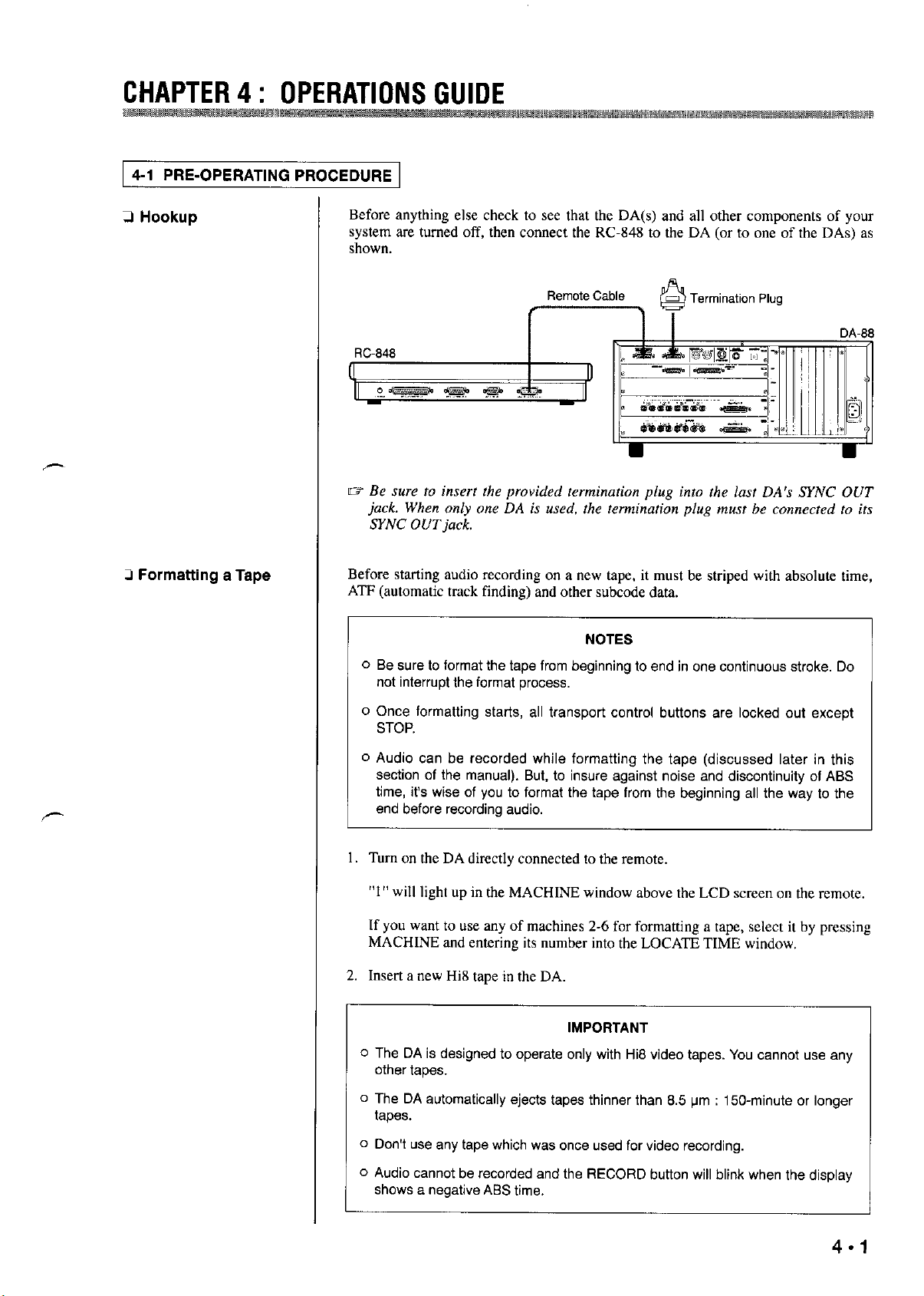
2 Hookup
Before anything else check to see that the DA(s) and all other components of your
system are turned off, then connect the RC-848 to the DA (or to one of the DAs) as
shown.
Remote Cable
,-
m Be nue to insert the provided termination plug into the last DA’s SYNC OUT
jack. When only one DA is used, the termination plug must be connected to its
SYNC OUTjack,
Zl Formatting a Tape
Before starting audio recording on a new tape, it must be striped with absolute time,
ATF (automatic track finding) and other subcode data.
NOTES
0 Be sure to format the tape from beginning to end in one continuous stroke. Do
not interrupt the format process.
o Once formatting starts, all transport control buttons are locked out except
STOP.
o Audio can be recorded while formatting the tape (discussed later in this
section of the manual). But, to insure against noise and discontinuity of ABS
time, it’s wise of you to format the tape from the beginning all the way to the
end before recording audio.
Turn on the DA directly connected to the remote.
1.
“1” will light up in the MACHINE window above the LCD screen on the remote.
If you want to use any of machines 2-6 for formatting a tape, select it by pressing
MACHINE and entering its number into the LOCATE TIME window.
Insert a new Hi8 tape in the DA.
2.
IMPORTANT
0 The DA is designed to operate only with Hi8 video tapes. You cannot use any
other tapes.
o The DA automatically ejects tapes thinner than 6.5 pm : 150-minute or longer
tapes.
o Don’t we any tape which was once used for video recording.
o Audio cannot be recorded and the RECORD button will blink when the display
shows a negative ABS time,
Page 20
CHAPTER4: OPERATIONSGUIDE
mzmm,@@8,
3, Rewind the tape all the way to the beginning.
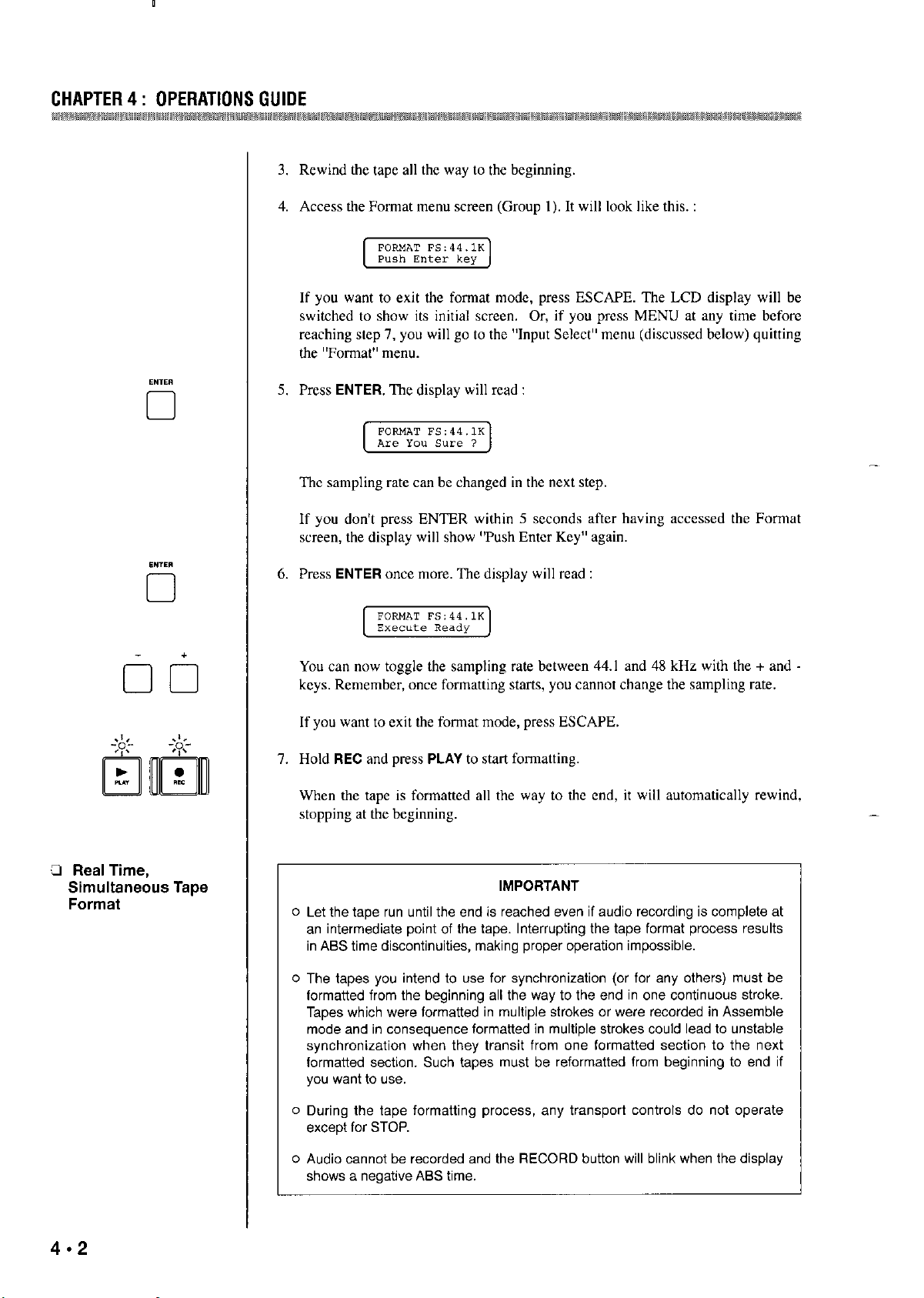
4. Access the Format me”” scree” (Group I). It will look like this. :
5, Press ENTER The display will read :
cl
[ ;~cm~“;~;a.~ J
If you want to exit the fomnt mode, press ESCAPE. The LCD display will be
switched to show its initial scree”. Or, if you press MENU at any time before
reaching step 7, you will go to the “Input Select” menu (discussed below) quitting
the “Fomut” me”“.
-
The sampling rate can be changed in the next step.
If you don’t press ENTER within 5 seconds after having accessed the Format
screen, the display will show “Push Enter Key” again.
3 Real Time,
Simultaneous Tape
Format
6. Press ENTER once more. The display will read :
[_I
You can now toggle the sampling rate between 44.1 and 48 kHz with the + and -
keys. Remember, once formatting starts, you cannot change the sampling rate.
If you want to exit the format mode, press ESCAPE.
7. Hold REC and press PLAY to start formatting.
When the tape is formatted all the way to the end, it will automatically rewind,
stopping at the beginning.
IMPORTANT
” Let the tape run until the end is reached we” if audio recording is complete at
a” intermediate point of the tape. InterrupUng the tape format process results
in ASS time discontinuities, making proper operation impossible.
” The tapes you intend to “se for synchronization (or for any others) must be
formatted from the beginning all the way to the end in ““e continuous stroke.
Tapes which were formatted in multiple strokes or were recorded in Assemble
mode and in cooseclwoce formatted in multiple strokes could lead to unstable
synchronization when they transit from “w formatted section to the next
formatted section. Such tapes must be reformatted from beginning to end if
y”” wzm~ to “se.
-
o During the tape formatting process, soy transport controls do not operate
except for STOP.
” Audio cannot be recorded and the RECORD button will blink when the display
shows a negative AEiS time.
Page 21

w
Hook up
5.
cz
Ifyou are usbzg
they
at-t?
1.
After you
system. Be
L
multiple DA sync
Make all connections with
the
DA-X&,
turned
off
have
connected all components of
sure
to
tur” o”
sys~?m L
assign them machine ID numbers ar
all the
CHAPTER 4 : OPERATIONS
basic example of which is shown in Chapter
WARNING
power
OFF.
this stage,
slaves
BEFORE the
your system,
switch on
mzuter.
Power
GIJIOE
while
to the
If you we using the
2.
Insert a new Hi8
o
The DA is
other tapes in the DA.
o
The DA automatically ejects tapes thinner than 8.5
tapes.
o
Don’t
Select a
the remote
beginning.
Press the remote CHASE and the “CHASE” will show in the LOCATE TIME
window.
designea
use .wy
slave
DA-3Ss,
Assign a different ID number to each of the
tape
tape which
DA with the MACHINE switch and the numeric keypad, then
REW
to rewind the
assign them machine ID numbers at this stage.
IMPORTANT
DAs.
into each of the machines.
NOTES
to operate only with
was
once used for video recording.
tape
Hi8
video tapes. You cannot
in the selected
lrn
:
150-minute
mxhine alI
use
or longer
the wy to the
any
press
Enter the selected machine’s ID number on the numeric keypad.
Access the
If
you
Press
You
Format
menu screen (Group
want to exit
ENTER. The
czm
change the sampling
the
format mode at this stage, press ESCAPE or
display
wil1 read
:
rate
in the next step,
I),
which will look like this
:
MENU,
Page 22

If you don’t perform the next step (8) within 5 seconds after having accessed the
Format screen, the display will switch back to read “Push Enter Key”.
8, Press ENTER once more. The display will read :
[WI
You can now toggle the sampling raw bewaxn 44.1 and 48 kHz with the + and
keys. Remember, once formatting starts, you cannot change the sampling rate.
If you want to exit the fonnat mode at this stage, press ESCAPE.
IMPORTANT
It is imperative that all the slaves are referenced to the same sampling rate as
the m&er.
9. Repeat the procedure outlined in steps 3 through 8 above for each of the
-
remaining slaves you want to use for simultaneous tape fonnat.
IO. Select machine 1 (the master).
If you intend to record audio while at the sane time the tapes are formatted, see
also the next paragraph, Audio Recording.
I I. Hold REC and press PLAY, and the simulmneous fonnat process starts, and also
the audio recording process if you have so programed.
0 Audio Recording
PRELIMINARY NOTES -
o Do rm use a tape once used in any different machines from the DA : a tape
used for video recording for example.
o We recommend that you use preform&ted new (blank) tapes for new
recordings.
0 Speaking of remembering, you can use only Hi8 video tapes in the DA. Tapes
thinner than 8.5 pm (150.minute or longer tapes) cannot be used, either.
I. Cheek to see that all elcmcnts of your system are correctly connected.
2. Turn on the DA if you have turned it off.
MEN”
0
Check to see that the correct number lights up in the MACHINE window.
3, Insert a formatted Hi8 tape into the DA.
4. Press MENU so the LCD screen reads :
Page 23

CHAPTER4: OPERATIONS GIJIOE
If you want to record audio from digital inputs, press the + or key. The screen
will change to read “Digital.” Pressing the key again will switch the screen back
to “Analog.”
If you have selected “Digital,”
the DA currently under remote control is
automatically referenced to the clock derived from its WORD SYNC IN, as
confirmed by the WORD CLOCK indicator being lit on the remote.
Press GROUP then MENU so the xrecn reads :
If “Vari” shows, press ENTER to select “Fix.”
Press the REC FUNCTION switches for the tracks to be recorded on. The
associated LEDs will start flashing to show that the tracks are in Record Ready
mode.
If you intend to record analog audio, adjust the output level controls of the source
machine as high as possible, without causing overscale reading on the DA’s
nleter.
Hold FtEC and press PLAY to start audio recording.
To terminate recording, press STOP.
IO. To insure against accidental erase, put the tracks into Safe mode by pressing their
REC FUNCTION switches again, Alternatively, you can press ALL SAFE.
Il. Rewind the tape to the beginning of the recording just done.
Playback
12. Make sure that your monitor speaker system is correctly connected to the DA,
then press PLAY.
13. To stop play (definitely or momentarily), press STOP,
Page 24

4-2 AUTOLOCATOR FUNCTIONS
A maximum of 99 cw points cz~” be stored into memory, to which you czm have the
tape be autolocated by pressing LOC.
It Setting Cue Points
Cue points cao be specified on the fly or with the numeric keys.
(1) On the Fly
Auto Storage :
During play, hit CUE STR at the desired moment,
If, when II~ MEMORY NO. is displayed, you hit CUE SIR, the TAPE TIME display
at that moment is loaded into the LOCATE TIME window and stored into the lowest
memory register available. If a MEMORY NO. is displayed, sa.y “02” for instance,
the captured time is stored into the “03” memory register. If “99” is displayed, the
time is stored into the “01” register. (The “00” memory register is for storing a
relative reference point, page 4 - IO,)
Manual Storage :
During play, hit the V key. The TAPE TIME at that momem will be read into the
LOCATE TIME window. Then press STR and specify a MEMORY NO, with the
numeric keys. To enter numbers lower than 10, first enter “O.“As soon as you enter
two digits into the MEMORY NO. window, the captured tape time is stored into that
number’s memory register.
(2) With the numeric keys
0 Checking Cue Points
3 Changing Cue Points
1. Enter the desired tape times with the numeric keys into the LOCATE TIME
window,
2. Press STR.
3. Press two digits on the keypad. They will be entered into the MEMORY NO,
window. To enter numbers lower than IO, first enter “0.”
As soon as two digits are entered, the current LOCATE TIME is stored into that
memory register.
I. Press RCL.
2. Press two digits which represent the memory from which you w.m to recall a cue
point, this recalls the cue point in that register into the LOCATE TIME window.
To “fine tune” a cue point recalled into the LOCATE TIME window :
I. Press the increment UP and DOWN keys until the display shows the correct time
point.
4-6
Page 25

CHAPTER4: OPERATIONS GUIOE
Press STR then enter a two-digit MEMORY NO. to store the fine tuned cw point
2.
into memory. The previous cue point in that n~emory is erased.
To entirely ChanQe any recalled we point :
Perform one of the “Setting Cue Points” procedures. Each time you store a new we
point into any MEMORY NO. register, the previous memory in that register is
erased.
13 Autolocating to One
of the 99 Cue Points
Before actually autolocating the tape to any cw point, know this :
You can locate the tape to a point plus pre-roll time if you “se the locate pre-roll
parameter. ‘ILK default time for the locate pre-roll parameter is “0”.
To enter a Locate Preroll time :
.-
Access the Locate Preroll meno ween (Group 2). It will look like this :
1.
Press the +/- key. The “See” number will change in I second increments.
2.
To move the cwwr to the “MS section, turn the JOG wheel to the left, An
alternative is to hold SHIFT and preys the minus key.
You can reset the Locate Preroll time to zero by pressing the plus key a.t the fame
time a~ the minus key,
To autolocate the ta.pe to a cw point :
Enter the desired MEMORY NO. with the numeric keys,
The cw point stored in that register will be recalled into the LOCATE TIME
window,
The tape will automatically be located to the time point currently shown in the
LOCATE TIME window, or to the locate point plus pre-roll as defined by the
locate pre-roll paranlet~r,
At the end of the autolocation function, the tape will stop unless AUTO PLAY is
engaged.
4.7
Page 26

LI Auto Play
-W
tl
CI Repeat Play Between
Two Memory Points
m
I =m I
-
aim
Pressing AUTO PLAY after or before LOC will cause the tape to start playing
whenever the autolocation function is complctc.
Repeat play disregards whatever Locate Preroll Time has been entered.
To set a play loop :
I. During play, capture the desired start point of loop by hitting the V key. That time
point will be read into the LOCATE TIME window.
You can ahema~ively enter the stat time with the numeric keys.
2, Press STR.
3, Press START to store the LOCATE TIME into mamx’y as the sort point of loop.
4, ‘IIK same mamu, capture the end point, and store it into manory by pressing
STR then END.
5. Press REPEAT m shrt repeat play
To interrupt repeat play :
Press STOP. To resume repat play, press PLAY.
To exit repeat play mode :
Press REPEAT again.
If yen press any Vansport control button during rep& play, the function pressed is
activated, and repeat play will start again if you-
(l) Recall the START or END point into the LOCATE TIME window, and prfx
LOC before or after AUTO PLAY (or, you an press PLAY after the LOC
function is complete) ;
OR
(2) Press PLAY if you ZIG? within the loop or at a lower point than the start point.
Page 27

CHAPTER4: OPERATIONSGUIOE
4-3 VARIABLE SPEED PLAYBACK
I. Before or after starting play, access the Pitch Control menu screen (Group 2). It
will look like this :
2. Press ENTER. The “Fix” will change to “Vari.”
3. Each time you press the + key, the pitch will increase by O.l%, up to a maximum
of +6.0%. If you press the - key, the pitch will decrease by 0.1%. down to a
minimum of -6.0%. If you hold the key, the % figures will scroll.
If you press ENTER after entering any pitch changes, the “Vari” will change to
“Fix” to show that your pitch changes are defeated although the % figures will not
be reset to “0.0 %‘I.
To clear the pitch mwvxy :
When the LCD screen reads “Pitch Control,” hold the + or -key and press the other.
4-4 ENTERING A TRACK DELAY TIME 1
Access the Delay Time menu screen (Group 2). It will look like this (we will
always refer to this as “Track Delay”):
If you want to insert delays in any other tracks than I, turn the SHUM’LE knob
so that the desired track number shows.
An alternative is to hold SHIFT and press MENU.
Press the + key. Each time you press the key, the display will increment in I
sample steps, up to a maximum of 7200 samples.
To decrement the number, press the - key. You can enter a minimum of -200
samples.
I sample (Fs) corresponds to 22.7 microseconds at 44.1 kHz, or to 20.8
microseconds at 48 kHz.
When the desired number has been entered, press ENTER.
The entered time that was blinking will glow solid.
You can press ESCAPE instead of ENTER to clear the entered blinking time to
the default steadily lit time.
4.9
Page 28

CHAPTER 4 : OPERATIONS GUIOE
You can also enter track delay time in 1 millisecond steps within the limits of -4
to IS0 milliseconds (IS0 ms is nearly equal to 7200 Fs). If you want to, hold
SHIFT and press ESCAPE to change “Fs” to “ms.” Then enter the desired time
with the + and-keys; then, press ENTER.
To defeat the entered delay time, hold either the plus or the minus key and press the
other. The display on the lower line will be reset to zero.
Setting one and the satne delay time for all (I to 6) tracks simultaneously :
Either operate the SHUTTLE knob, or hold SHIFT and press MENU, until “All” is
displayed on the upper line, ‘Ilxn, enter the desired time with the plus and minus
keys, Once the desired time is displayed, press ENTER.
1 4-5 RELATIVE REFERENCE TIME INDICATION 1
The TAPE TIME display can be switched to show clapsed time from an optionally
specified point on the tape inserted in machine I.
-
ccl
El
Access the Display Time menu screen (Group 2). It will look like this :
Press the +/-key.
The “Absolute” will change to “Relative.”
Press the v key when the tape reaches the point you want to define as a “zero”
reference point. The TAPE TIME at that tnotne”t will be read into the LOCATE
TIME window. You cztn also enter the desired time with the numeric keys.
Press STR, then press 0 two times on the keypad. “00” will show in the
MEMORY NO.window.
From now on the TAPE TIME display will give elapsed time from the time point
you have just stored into the MEMORY NO.00 register until you establish a new
reference point or switch the display back to Absolute mode.
To locate the tape to your reference point :
Press RCL, and press 0 two times to specify MEMORY NO.00. The LOCATE TIME
display will read O@OQO@OO. Then press LOC.
4.10
If ZI Locate Preroll time has been entered, the tape will be located to ZI point plus preroll zts defined by the locate prc-roll parameter.
To establish a new reference point :
Repeat the above procedure. Exh time a new rcfcrcncc point is stored into memory,
the previous tnemory is erased.
Page 29

1 4-6 PUNCH-IN RECORDING 1
CHAPTER4: OPERATlONSGlJlDE
To switch the display back to Absolute time indication mode :
When the LCD screen reads :
press the plus or minus key, The “Relative” will change to “Absolute.”
First, check to see that the recording source is plugged into the correct input jack on
the rear of the DA which is currently under remote control, and which contains the
tape you wish to correct (punch) (i.e., into input 2 for punching in on track 2 etc.).
0 Entering a Crossfade
Time
cl
Click-free punch in and out of record is ensured by a crossfade action which defaults
to 10 milliseconds. If you want longer crossfades :
1. Access the X-Fade Time menu screen. It will look like this :
(71
If any other crossfade time has locally been entered on the DA, that time will
show.
2. Enter numbers by pressing the + key. Each time you press the key, the number
will increment by IO ms, up to 90 ms,
To decrement the number, press the -key.
3. Once the desired longer time than IO ms is displayed (it should be blinking),
press ENTER.
The display will glow solid,
0 To switch all DAs (1 to 6) to the same crossfade time, select machine I and “All”
at the Key Mode menu, then enter the desired time at the X-Fade Time screen.
0 Rehearsal
0 With the DA-88 : Check to see that REPEAT is not activated. If it is, press the
key to turn its LED off or RHSL cannot operate.
0 You can abort reheana.1 by pressing CLEAR at any time when RHSL is blinking
or on solid.
0 If the exact punch-in and out points are already known to you, you can enter those
time points with the numeric keys into the LOCATE TIME window, so they can
be stored in the IN and OUT memories. Othcwisc, specify both points on the fly
as instructed here.
Page 30

CHAPTER4: OPERATlONSGUlDE
I. Locate the tape to a point a few seconds before the point you want recording to
2. Press the REC FUNCTION switch of the punch-in track so the associated LED
3. Press INSERT so its LED lights.
4.
5.
6. When the desired punch-in point is reached, hit REC.
start from.
blinks to show that the track is in Record Ready mode,
Press RHSL so its LED starts blinking to show that the selected machine is in
Rchcarsal Setting mode.
Press PLAY to start playing.
That point on the tape is stored into memory defined as the punch-in point,
DA-88 : Since you are in Rehearsal Setting mode, the monitor does not switch
from tape to source (input).
DA-38 : The monitor switches from tape to source the instant you hit REC.
1.
When the point where you want to punch out is reached, hit PLAY,
That point on the tape is stored into memory defined as the punch-out point,
The RHSL LED that was blinking will turn on solid to show that the machine is
switched from Rehearsal Setting mode to Rehearsal mode.
After a 3.second postroll, the tape will rewind, stopping at a point 5 seconds prior
to the punch-in point just set.
0 The preroll time defaults to 5 seconds, and the postroll time to 3 seconds,
Both we optionally adjustable, as explained later.
Note, the Locate Preroll Time (p.4 * 7) has nothing to do with the punch-in preroll
time.
8.
Press PLAY to check the punch-in and out points for accuracy.
The monitor will switch from tape to source (input) when the punch-in point is
reached, and back to tape at the punch- out point.
4.12
If tbc monitor does not switch exactly at the desired points, either repeat steps 4.8
or recall the punch-in/out point into the LOCATE TIME window by pressing
IN/OUT, and fine tune it with the increment UP and DOWN keys.
9
Practice the performance until you are sure that you will get it right when actually
recording, Remember, once you punch in “vu existing material, that original
signal is permanently erased.
Page 31

CHAPTEtl4: OPERATIONSGUIDE
Q Actual, Auto Punch In
and Out
The INSERT and RHSL LEDs should still light solid. All tracks should be in Safe
mode except the one you intend to record on.
IO. Press AUTO IN/OUT so its LED starts blinking.
The RHSL LED that was on solid will turn off.
11, Press PLAY.
‘Ilx tape will punch in and punch out of record at the preset points. After a 3.
second (or optionally set time) postroll, the AUTO IN/OUT LED that was
blinking will glow solid and the tape will rewind, stopping at the preroll start
point.
To review the result :
Press PLAY. The tape will play to the postroll end point, and r-wind, stopping at the
,-
preroll start point.
To record again using the same menvxy points :
Press AUTO IN/OUT. I& LED will s&n blinking as before, then press PLAY.
To exit AUTO IN/OUT mode :
Press CLEAR.
0 Setting preroll and
pos.Woll times
Relationships between the punch-in related modes and the RHSL and AUTO IN/OUT LEDs
The preroll time is factory preset to 5 seconds, and the postroll time is to 3 seconds.
You can only enter longer times than them.
Enter the desired time into the LOCATE TIME window with the numeric keys.
The pre- and postroll times are second-accurate. To enter 6 seconds, press 6.0.0.
Effective entries are up to a maximum of 59 minutes, 59 seconds.
Press STR,
Press PFlE (or POST) to store the time just entered into memory a.s the prcroll (or
pos~roll) time.
If you press PRE after a preroll time has been entered, the point where the pmoll
starts from is displayed in the LOCATE TIME window. So you can promptly
locate the tape to that point using LOC, and fine rime it with the UP and DOWN
keys.
4.13
Page 32

1 4-7 COPYING TRACKS (DA-38 only)
To copy track 3 m track 5 for example :
I. Access the Track Copy maw (Group Z), which will look like this :
You cannot access this menu if the DA-38 is not currently under remote control,
2. To select a txgct track, enter “5” in the “Tr” field in any of three ways :
0 Turn the SHUTTLE knob ;
0 Hold SHIFT and press MENU ; or
0 Press the REC FUNCTION switch that corresponds to track 5 of the DA-38,
(Note, it’s not necessarily the no.5 switch. It depends on the connection.)
3. To select a source track, press the + key until “Tape 3” shows. If you go past it,
press the -key.
4. Press ENTER to change the “Off’ to “On”.
[?$%-z?g
5. Making sure that only track 5 is record-enabled, hold REC and press PLAY to
start copying,
In a similar way, you cart copy tracks of one DA-3X to tracks of another, For tnore
information, see the DA-38’s manual.
4-8 SHUTTLE MONITOR (DA-38 only)
When you rotate the SHUTTLE knob for reel rocking to locate specific points cm the
tape, what you hear depends on whether the shuttlc monitor mode is enabled or not,
as shown in the table below,
To enable or disable the shuttle monitor function :
1. Access the Shuttle Monitor me”” (Group I), which will look like this :
You camtot access this mc”u if the DA-38 is not currently under remote control.
-
4.14
Page 33

CHAPTER4: OPERATIONS GUIDE
vice versa, as required.
Shuttle Mmitor Mode REC FUNCTION Off REC FUNCTION On
1 Off (factory preset) 1
Tape
I
Tape
I
1 4-9 SELECTING A TDIF INPUT SIT LENGTH (DA-38 only) 1
To send and receive digital data through the TDIF-1 !JO port on the rear panel of the
DA-38, you have to select a bit length depending on the port connection.
Three options are provided : 16, 20, and 24. Factory preset is 16.
I. Access the TDIF Input Bit mmu, which will look like this :
[VI
You cannot access this mm if the DA-38 is not currently under remote control.
2. By operating the + and-keys, have the required option show ~II the screm
Select 24 if the DA-3X is connected to another DA-38, or select I6 if it is
connected to the DA-XX,
4.10 ENABLING THE DITHER FUNCTION (DA-38 only)
I
I. Access the Dither mmu, which will look like this :
lzzrl
You cannot access this mmu ii’ the DA-3X is not currently under remote control.
2. Press either the + or the -key to change the “Of?’ to “On”,
4.15
2. PRSS the + or the -key to change the “Off’ to “On”, or
Page 34

;,,,,
SYNCHRONIZING MULTIPLE DA’S
Q Connections
You can hook up a maximum of 16 DAs and can handle a total of 128 tracks in sync
without using any external synchronizer/controller.
Make sure that your whole system is turned off, connect the RC-848’s REMOTE
OUT to the first DA’s REMOlE IN, its SYNC OUT to the second DA’s SYNC IN,
its SYNC OUT to the third DA’s SYNC IN, and so on, as shown.
rz Be sure to insert the provided termination plug into the lasf DA’s SYNC OUT
jack.
Remote Cable
PW-atx?
Termination Plug
-
0 Machine ID
(Identification)
Numbers
Cl Synchronization
If your system is made up of DA-88s and DA-38s and the first machine (master)
is a DA-88, locate the MACHINE ID switch on its rear and set it to “0”
(remember ,Vote cm page 3 * I) while the system is still turned off. If the second
machine is a DA-38, select “2” (not “1”) a.t its IocaI “ID Selection” menu
(“id.SEL”) AFTER perfomGng step 1 below.
1. After you have connected all components of your system turn on the system. (Be
sure to turn cm all the slaves BEFORE the master.)
If your system incIudes one or more DA-38% assign them ID numbers, as
outlined above.
2. Press the remote CHASE.
“CHASE” will show in the LOCATE TIME window,
3, Specify the machine you want to slave to machine I with the numeric keys.
If “CHASE” goa out before you enter numbers, press CHASE again.
The entered number should be flashing rapidly in the LOCK STATUS window,
showing the slave under control is fast winding on its way to the same time point
as the master. It will flash slowly once the slave is parked at the sane address as
the master.
If you want other DAs (machines 2-6) to slave to machine 1, repeat steps 2 and 3
for each of them. Or use the next capability :
Page 35

CHAPTER 5 : SYNCHRONIZING MULTIPLE DA’S
Enabling/Disabling CHASE mode on all machines 24 at one time :
Just press CHASE + 0. If the lowest numbered slave is NOT in CHASE mode at this
moment, it will go into CHASE mode, and so will all other slaves. Or they will all
exit the CHASE mode if the lowest numbered slave is in CHASE mode.
If there are additional slave DAs, press CHASE on each of them.
4. Pressing any remote transporl button will cause the master and slaves to trigger
the same function.
The LOCK STATUS number(s) will glow solid when the slave(s) start playing
locked to the master.
Controls Having Effect On MachIne 1
When a.“y of machines 2-6 is under control and in CHASE mode, the following
controls have effect o” machine I :
STOP, PLAY, F,FWD, REW, REC, LOC, and JOG/SHU’ITLE.
Consequently, the LEDs associated with those controls show the status of the
master tramport.
CHASE
cl
0 Entering an Offset
To release slaves from the master :
1. Press the remote CHASE again. “CHASE” will again show in the LOCATE TIME
window.
2. Press a number on the keypad. The number pressed will go out from the LOCK
STATUS window to show that number’s machine cm act independently of the
master.
Repeat steps 1 and 2 for other slaves as required.
To release all the slaves from the master at one time :
Press CHASE + 0.
Offset can be entered automatic~~ly using the ENTBR key or, if the necessary offset
value is known, manually using the numeric keypad or the plus and minus keys.
(1) Auto Entry
This procedure can be used only when “ABS” is selected at the Time Mode mew
(Group 3).
MAc”,NE
cl
The current difference between the master and slave locations can be stored in
lnelnory as a” offset, as follows :
I. Press MACHINE,
“Select” will show in the LOCATE TIME window.
2. Press the number that corresponds to the slave you want to offset.
The pressed number will light up in the LOCATE TIME window.
Page 36

CHAPTER 5 : SYNCHRONIZING MULTIPLE DA’S
3.
Locate the slave to the desired sync point.
4.
Press MACHINE then 1, and locate the mister to the desired sync point.
5.
Access the Machine Offset screen. It should look like this :
6.
The display on the upper line in the screen shows the number that corresponds to
the slave under control. ‘Ibe number will increment as you turn the SHUTTLE
knob or press MENU while holding SHIFT.
Press ENTER.
The RC-848 automatically calculates and displays the necessary offset value on
the Swx”.
Repeat for other slaves as required.
(2) On the Numeric Keypad
Access the Machine Offset screen, and turn the SHUTTLE knob or hold SHIFT
and press MENU to display the number that corresponds to the slave you want to
offset.
Enter the desired offset value on the numeric keypad into the LOCATE TIME
window.
Once the desired value is displayed, hold SHIFT and press ENTER.
The LOCATE TIME display will be read into the swan.
Repeat for other slaves as required.
(3) Direct Entry in the Machine Offset Menu
Access the Machine Offset screen, and either turn the SHUTTLE knob or hold
SHIFT and press MENU to display the number that corresponds to the slave you
want to offset.
Hold CLR and press f.
OOzO@OO9O will start blinking in the LOCATE TIME window, to show that the
unit is in Direct Keying-in mode.
Enter the desired offset value on the numeric keypad.
5.3
As you type numbers, they will be entered directly in the menu screen, not into
the LOCATE TIME window.
To change the + (ahead) to - (behind), and vice versa, press either of the plus and
minus keys.
Page 37

CHAPTER 5 : SYNCHRONIZING MULTIPLE OA’S
4. Press ENTER to store the setting.
If you press ESCAPE instead of ENTER, the emercd numbers are cleared and
you’ll exit the current mode.
5. Repeat for other slaves as required.
(4) Using the Plus and Minus Keys
Perfom step I above, then use the plus and minus keys to display the desired
offset value on the lower line in the screen.
To move the cursor, turn the JOG wheel or hold SHIFT and prtx the plus or
minus key.
To change the + (ahead) to - (behind), and vice versa, press either of the plus and
minus keys.
Repeat for other slaves as required.
Cl Syncing with Offset
0 Fine Tuning Offset
Values
- +
00
Ll Selecting a Key Mode
Press CHASE then pre?.s a number. The slave that corresponds to the number pressed
will be axoloca~ed to a point either ahead or behind the master as defined by the
offset value. Repeat for each of other slaves. Or you can “se the ‘All Chase On’
function explained on page 5 - 2.
On the Machine Offset screen move the cursor to the right of the “frames” column
using either the JOG wheel or the SHIFT and plus or minus key so the xr~en looks
like this :
Then, hold down either the plus or minus key. The frame numbers will increment,
and after a while, overfiow, causing the second numbers to increment. Unless you
release the key, the minute numbers and then the hour numbers will increment
likewise.
To disable offsets :
Access the Machine Offset menu showing the desired machine number, and hold the
+ or -key and press the other. The display will be cleared to zero.
At the Key Mode men” yo” ca” select whether the ALL SAFE/REC READY, ALL
INPUT, AUTO INPUT, and INSERT keys have effect on the master machine only or
on all the rnas~cr and slave machines a.t once.
I. When machine I (the master) is under control, access the Key Mode menu
(Group I) to check or change the current selection, ‘Ibe menu screen will look
like this :
5*4
Page 38

CHAPTER 5 : SYNCHRONIZING MULTIPLE OA’S
2. If “All” is displayed and you want the keys specified above to be effective only
on the master, press either the plus or minus key to change the display to
“Individual.”
0 Digital Dubbing
Between Two DAs
With digital recording, “o matter how tna.“y times dubbing is repeated, no hiss or
distortion is added ; you can copy important multitrack tapes as many times as you
need to create work talxx or copies for distribution without having to worry about
a”y deterioration whatever.
Always use machine I as the source machine. The target machine may be a.“y cone of
machines 2-6.
-
I. Making sure that both the source and target machines are turned off, connect one
end of the optional PW-gSD cable to the master’s T-DIF UO port, and connect the
other end of the cable to the T-DF l/O pai o” the DA yc~” want to “se as the
target machine,
The master’s SYNC OUT should also be connected to the target machine’s SYNC
IN.
rz Be sure to insert the provided termination plug into the last DA’s SYNC OUT
jack.
2. Turn on both machines.
3. Insert your master multitrack tape in machine 1, and insert a fomxmed blank
tape in the tuget machine.
4. Check to see that the source machine’s all REC FUNCTION switches are turned
off.
If you are using the DA-38 as the mater (source), skip the next two steps (#5
and 6).
Page 39

CHAPTER 5 : SYNCHRONIZING MULTIPLE OA’S
5. Access the Output Timing menu screen (Group I). It will look like this :
6. Press the + or-key to change the “Analog” to “Digital.”
Press all the 8 REC FUNCTION witches (9-16 if machine 2 is selected, 17.24 if
machine 3 is selected, etc.). The associated LEDs will start flashing to show the
tracks arc in Record Ready mode.
Press CHASE. “CHASE” will show in the LOCAm TIME window, then enter a
number to specify the target machine.
The number just entered will start flashing rapidly in the LOCK STATUS
window, showing the target machine is being located to the same time point as the
source machine. The number will flash slowly when that time point is reached.
When the LOCK STATUS indicator stops flashing rapidly and starts flashing
slowly, hold REC and press PLAY on the remote. The source machine will start
playing, and the target machine will automatically start recording.
IO. When dubbing is complete, press STOP.
To copy timecode as well :
The SY-88 Sync Board must be installed into both the source and target machines.
For more information, see the section, USING THE RC-X48 WITH THE SY-XX.
Page 40

1 6-1 MACHINES WITH A PARALLEL PORT
If your machine has a parallel port and is connecwd to the
EXT I (ACCESSORY 1) connector, press 7. “El” will
light up in the MACHINE window,
The STOP LED will flash if machine El is selected while
the EXT I (ACCESSORY I) connecdon is not achieved.
6-2 EVENT OUTPUT FACILITY
(AVAILABLE UPON REQUEST ONLY)
If an asterisk (*) appears to the left of “Width,” it
shows that Event I is enabled at the Event On/Off
menu (discussed below) and that y”” cannot change
the current Polarity and Width settings. To change the
current settings, go to the Event On/Off menu screen
first, then press ENTER to sclcct “Off,”
Select zi polarity and pulse width using the plus and
minus keys. (To nwe the cursor up/down, opera
the JOG wheel or hold SHIFI and press the plus or
minus key.)
Repeat for other even& as required. The event number
on the upper line changes as you turn the SHUlTLE
knob or press MENU while holding SHIFT.
Selecting Event Points
To use this facility 8 dip-switch (#3) located inside the
RC-646 should be set to Up/On position, and this
should be done only by a qualified service person.
e
5 Event output ports czu be available using PLAY, FF,
REW, STOP and REC output pins of EXT I connector
(#l, 2, 3, 5 and 6). Each port cz~” output a one-shot pulse
twice.
Event point (time) is selected from MEMO 01 to 99. An
IN memory can also be used as an event trigger point
(discussed below),
Event pulse width can be set from 00 to 990 ms
(milliseconds) in IO ms steps,
NOTE
The Event Pal and Width menu and also the Even
On/Off mf?nu are accessible only when the #3 dipswitch is set to ON (see Learning above) and
machine I or 9 is put under remote control.
I. Access the Event On/Off tnenu screen. It will look
like this :
m
2. Use the plus and minus keys to enter into where the
01 is currendy displayed the number that corresponds
to the memory in which a first shot point is stored,
Likewise, select a second shot point memory. (The
cursor can be moved left and right by operating the
JOG wheel or by holding SHIFT and pressing either
the plus or minus keys,)
0 If you specify only one MEMO No,, only one
event pulse will be output,
3. When the scrce” looks OK, press ENTER. The “Off’
will change to “On,”
0 To modify the settings, first switch the “On”’
display to “Off’ by pressing ENTER.
4. Repeat for other events as required.
Selecting a Contact Polarity and Pulse Width
1. If the RC-848 is on, turn it off, and set the #3 dipswitch as specified abow,
2. Switch on power m the RC-848, and access the Event
PoUWidth menu screen. It will look like this :
Programing Events to Be Triggered at an “In
Event” Point
If the “Events” are referenced to points stored into
numbered memories (01 to 99), the “In Events” arc
referenced to a point stored into IN memory,
Events referenced to an IN point can be programed to
start user entered frames before that IN point, typically to
overcome the response time discrepancies between the
event devices.
Page 41

CHAPTER6: CONTROLLlNGOTHEREGLIlPMENTFROMACCESSORY"l"
Settings at the Event Pal/Width menu are valid to Events
refexmced to an IN memory, too.
Access the Ret In Event menu screen (Group I), It
I.
will look like this :
Change the In Event number on the upper line as
2.
necessary by operating the SHUTTLE knob or by
holding SHIFT and pressing MENU.
3.
Enter the desired frame numbers in the Reaction field
by operating the + and -keys. (Seconds can also be
entered if necessary.)
-
4.
After having entered the correct reaction time, first
access the Event OdOff menu, which looks like this :
then, hold SHIFT and press ESCAPE to access the In
Event menu, which looks like this :
Enter the same number as in step 2 above, and the
5.
current IN memory point will show on the second line
of the menu and to the right will show the fwnes you
have entered in step 3 above.
6.
Press ENTER and the “Off’ will change to “On” to
show that the In Event is enabled.
Repeat for other In Events as required,
7.
-
r
NOTE
The time data the RC-848 uses to control events
comes from the DA, and only by this data travel time
(a few frames) will the event lag behind the time
points you’ve selected at the mew.
Page 42

When connecting the RC-848 to arty TASCAM machines* via the “Accessory 2” connector, it is necessary to use an
isolation cable. This isolation cable is made by TASCAM and it is model number PW-66AC2.
‘TASCAM machines with Accessory 2 port include MSR-24/24S, MSR-16/16S, TSR-E, 236/236S, 666, 644,
134/134B, CD-601, RC-701 and RC-601.
7-1 TASCAM MULTITRACK CASSETTE
RECORDERS
Q Connections
First check to see that the machine you wmt to connect to
the rernotc is turned off, and that the deck’s baud rate is
set to 9600.
Then connect the rcmotc EXT 2 (ACCESSORY 2)
connector to the deck’s ACCESSORY 2 connector using
the optional PW-88AC2 cable.
25 : Mutes all inputs of the deck at once.
26 : Unmutes all inputs of the deck at once.
46 : When machine “E2” is selected, the TAPE TIME
display acts zu ZJ tape counter, and pressing switch 48
resets both the remote and deck’s tape counvxs.
All other REC FUNCTION switches cannot operate.
TAPE TIME display
This acts as a conventional mpe counter. You can press
the REC FUNCTION #48 key to reset the counter to
00.00 to use any point on the mpe as ZI starting point for
time reference.
When the tape rewinds past the 00.00 point, ZI “-” will
show in the H(our) window.
To locate the tape to the counter zero point, press 0. The
MEMORY NO, display will show 0. Then press LOC.
-
0 Machine Selection
1, Press MACHINE.
“Selecf’ will show in the LOCATE TIME window.
2. Press 6 on the keypad.
“E2” will light up in the MACHINE window.
Cl Remote Functions Changed/Limited
REC FUNCTION switches
1-8 (or 1-4 if the 64l is connected) : Only these switches
act as the REC FUNCTION switches.
JOG/SHUlTLE switch
Puts machine E2 into Pause mode.
RHSL and AUTO IN/OUT switches
Provide the same functions a.s when any DA-88 is under
remote control, but their LEDs flash throughout the
process; they don’t glow solid.
Numeric keys
When STR or RCL is activated, only 1 and 2 on the
numeric keypad can operate to establish &vo memory
points or to recall them into the LOCATE TIME window.
To locate the tape to either memory point, press RCL,
then press 1 or 2 on the keypad. The memory point will
be recalled into the LOCATE TIME window, then press
LOC.
7*1
Page 43

1 7-2 TASCAM OPEN-REEL RECORDERS
33 : Turns on the machine’s ALL INPUT function.
34 : Turns off ALL INPUT,
0 Connections
1. Make sore that your machine is turned off,
2. Check to see that the baud rate is set to 9603 on the
machine. If it is at any other position, set it to 9600.
36 : Turns oo the machine’s AUTO INPUT function,
37 : Turns off AUTO INPUT.
39 : Turns on the machine’s AUTO PLAY function,
40 : Turns off AUTO PLAY,
48 : When E2 is under remote control, the remote TAPE
TIME display acts as a conventional tape counter, and
pressing switch 48 resets it to 00.00. The local tape
counter also is reset at the sane time,
All other REC FUNCTION switches are locked out,
TAPE TIME display
This acts as a conventional tape counter, providing
clapsed time from any point on the tape specified as a
starting point (0.00.00) by pressing the REC FUNCTION
#48 key. Reading is op to a maximum of I hour, 39
minutes, 59 seconds, and down to a minimum of -I hour,
39 minutes, 59 seconds. When the tape goes past these
limits, the coontcr is automatically rcsct to 0.00.00,
3. Connect the remote EXT 2 (ACCESSORY 2)
connector to your machine’s ACCESSORY 2
connector using the optional PW-8SAC2 cable,
0 Machine Selection
1. Press MACHINE,
“Select” will show in the LOCATE TIME window
2. Press 8. “E2” will light up in the MACHINE window,
0 Remote Functions Changed/Limited
REC FUNCTION switches
1-8, 1-16 cn I-24 (depending on the number of tracks
available on your machine) : Only these switches act as
the REC FUNCTION switchcs.
28 : Twos on the machine’s SYNC LOCK function
29 : Turns off SYNC LOCK.
When the tape rewinds past the 00.00 point, a “-” will
show in the H(our) window.
Numeric keys
When a TASCAM reel-to-reel deck is under remote
control, yoo can store a maximum of 20 autolocating
points into the MEMORY NO.00 to I9 registers. So,
when STR or RCL is activated, pressing 20 or higher
numbers on the keypad has no effect.
STOP LED
Flashes when the machine’s right tension arm is dropped
to its “off’ position for edit porposw
31 : Turns oo the machine’s INSERT function,
32 : Turns off INSERT,
7.2
Page 44

7-3 TASCAM CD PLAYERS
0 Connections
First check to see that your CD player (or its remote
control unit) is turned off and that the baud rate is set to
9600.
Then co”nect the remotc EXT 2 (ACCESSORY 2)
connector to the CD player’s (or to its remote control
unit’s) ACCESSORY 2 connector using the optional PW88AC2 cable.
RC-848
II
n
- Track and Index Search Operations u
I
Press MENU until the LCD screen reads :
2
If you want to locate the CD pickup to the beginning
of a track, press the +/- key. ‘I~K “Index Search ” will
change to “Track Search”.
3
Press numbers on the numeric keypad to enter the
desired track number into the LOCATE TIME
window. Then, if you have selected “Index Search,”
enter the desired index number.
In “Index Search” mode the first two digits represent a
track, and the next two digits represent an index (e.g.
I213 shows track 12, index 13). In “Track Search”
mode if you enter three or four digits, only the last
two digits are valid (e.g. I213 only shows track 13).
4
Press LOC to locate the pickup to be specified point
If you want to index search when your CD player is in the
stop mode, press stop to have the player enter Pause.
0 Machine Selection
I. Press MACHINE.
2. Press 8 o” the keypad.
“E2” will light up in the MACHINE window.
tI Remote Functions Changed/Limited
Menu scrsens
Only the following menus can be accessed,
0 AutoCue
0 Single
0 unit Select
0 Search Mode
0 Display Select
Only PLAY, STOP, and LOC can operate. LOC is used to
start search operations (see right column of this page).
-
Page 45

7-4 REMOTE FUNCTIONS NOT OPERATIONAL
Cassette Deck
REC FUNCTION YES*
CUE STR
YES* : Operational, but functions limited or changed, as specified on pages 7-1 & 2.
Page 46

B-i TURNING THE CHASE MODE OF DA-60
When an analog VTR or a DAT is under remote control :
MKII ON OR OFF
REC FUNCTION Switch Is Used To
Check to see that the DA-60 MKII is turned off, then
connect the DA-60 MKII’s IZS-422 port to the remote
EXT 3 port.
To have the DA-60 MKII go into Chase mode, press
#42
When a digital VTR, a TASCAM machine, or a machine
not defined in the remote is under remote control :
#41
control Audi” 1 Insert mode.
control Audio 2 Insert mode.
CHASE, then press 9 on the keypad (regardless of
whatcvcr machine is currently under remote control).
REC FUNCTION Switch
#41
To have the DA-60 MKII go out of Chase mode, press
CHASE then 9.
“E3” will blink rapidly in the MACHINE window to
show that the DA-60 MKII is chasing the master. When it
locks to the master, the indicator will blink slowly.
#42
#43
#44
#45 switch Digital Audio 3 On/Off.
#46 switch Digital Audio 4 On/Off.
Is Used To
witch Audio 1 On/Off.
switch Audio 2 On/Off.
switch Digital Audio 1 On/Off.
switch Digital Audio 2 On/Off.
S-Z HAVING A DA/VTR SYSTEM DROP INTO
AND OUT OF RECORD (FUNCTION
ranote.
AVAILABLE UPON REQUEST ONLY)
Thus, tracks of machine 6 cannot be controlled from the
WARNING
To “se this facility, a dip-switch (#4) located inside the
FlC-848 should be set to Up/On position.
This switch setiing should be done only by a qualified
sewice person.
When the dip-witch specified above is set to its Up/On
position :
0 The initial screen reads “Video Ret ACCEPTABLE !”
when pressing MACHINE then 9.
O A VTR drops into and out of Insert Record as you
have the DA-88 drop into and out of record (only
while in “Split” mode.)
The Split mode is explained in Chapter 12
0 A VTR punches in and out as machine I does so at
points selected for AUTO IN/OUT operation.
0 You can “pcratc the following REC FUNCTION
witches.
Page 47

USING THE RC-848 WITH THE SY-88
This section of the manual provides information CI” timecode-controlled
operations and operating procedures for controlling machines (typically, a
VTR) from EXT 3.
Information about the FIG348 in the following pages supersedes that
information in the current manual for the SY-88.
In the following we us? “DA-SW to cover all the models (Version 4.00 or not)
unless otherwise noted.
Page 48

GROUP 3
-
Page 49

Page 50

,
,
,
Page 51

MACHINE (GROUP 6)
Page 52

Time Entry Method A
lime Entry Method C
-
-
Page 53

CHAPTER 9 : ACCESSING THE MENU SCREENS
INSTANT ACCESS TO THE MENUS YOU USE
MOST FREQUENTLY
A maximum of IO tnenus czx” be stored so y”” czm
directly zcess them by pressing SHIFT at the satne time
as 3 numeric key (0.9) z+t the initial screen. ‘l%is feature
czm be used when machine 9, that is, a machine
connected to the EXT 3 connector is under remote
control.
Selecting and storing meow is explained in Chapter 2,
MENU SCREENS EXPLAINED
Menus marked with zm asterisk (*) can be accessed when
the SY-88 is installed in machine I,
0 Group 3
Gen Starl Time
For selection of a time code address where the generator
will bcgi” generating timecode (p.10 - I).
Generate Reset
The generator will begin generating timecode from the
user entered time or will continue generating from the last
number displayed before stopping the geoemtor, as
controlled from this men” (p.10 - 2).
Time Mode
This screen is where y”” determine whether a DA-SS/SY88 system you’ll select is put u”derABS time or timecode
c0ntr0l (p.10. I),
Playback T/C
Dctennioes whether the ABS time is converted into
SMPTE/EBU code before reaching the TIME CODE
OUT jack or off-tape timecode is sent out of the jack
(p.10 * 2).
When selecting either Pull Up mode, set the CLOCK
switch to INT for the tape to play or record at 0.1%
“pulled up” speed,
Error Bypass
Once the slave or slaves axe locked to the master, the RC-
848 overrides an absence of valid code of a maximwn of
IO or 30 frames on the mister, zts selected at this men”.
Park Position w
Compensates for a lag in a slave DA-88’s play time
(p.ll - I).
0 Group 4
T/C : External t*J
Shows the timecode numbers and the code type from a
master (p.1 I - 2).
Note, “3ON” is displayed to show either 30 or 29.97 NDF
code.
T/C : Abs Diff tw
Shows the cwrent absolute difference between the master
and slave timecode numbers or the relative difference
between them, which is obtained by subtracting offset
values from the absolute difference (p.1 I . 2).
T/C : Offset w
Allows y”” to enter subfmme offsets “o the numeric
keypad or on the fly when the machine under control is
playing locked to a mister (p.11 . 2).
T/C Type (Tape)
This scree” shows the type of off-tape code from a
DA-88.
Cl Group5
Reference T/C
Selects 30 NDF/29,97 NDF/29.97 DF/25/24 codes when
laying down timccode on tape (p.10 * I) or for timecode
controlled synchronization Shown in parentheses is the
code type used by an external machine,
Fs Shift
‘Ibis men” is where Pull Up Drop, Poll Up Non Drop, or
Pull Down is selected with the plus and minus keys to
accommodate specific NTSC environments. Selections at
the Reference T/C men” above we overridden and the
DA-88 under control is referenced to 29.97 DF, 29.97
NDF, and 30 NDF, respectively. Be sure to select Off
when the Fs Shift function is not necessary. When the
function is activated, an asterisk (*) is displayed in the
Reference T/C mew screen, showing this menu is locked
EXT 3 Cont. Mode
Determines whether the RC-848 controls either both ZI
slave DA-88 and zi master machine connected to the EXT
3 connector or only the master (pp.12. I & 2).
EXT 3 Timer Mode
Selects timec”de/timer I as the time reference of your
VTR (P.12.2).
Frame Display
Similar to that for machines I-6 (Group I), but it
determines whether the frame numbers entering the EXT
3 connector are hidden or not.
Page 54

CHAPTER9: ACCESSINGTHEMENUSCREENS
mmm8m,
Park Position
Similar to that for machines I-6 (Group 3), but it controls
the park position of a machine connected to the EXT 3
co”“ector.
Event (Pal and Width)
Similar to the one that belongs to Group I, but it allows
you to configure the RC-848 for event units that axe
controlled using the time data entering the EXT 3
co”“ect”r.
Flee In Event
Similar to the one that belongs to Group I, but it takes
care of event units that we controlled using the time data
entering the EXT 3 connector.
0 Group6
T/C : External
Shows the timecode numbers and the code format
entering the EXT 3 connector,
T/C : Rel Diff
Similar to the one that belongs to Group 4, but it selects
ReVAbs when a machine connected to the EXT 3
connector is assigned as master,
T/C : Offset
Similar to the one that belongs to Group 4, but it allows
yot~ to enter an offset when a machine connected to the
EXT 3 connector is assigned as master.
Locate Preroll
Similar to the ox that belongs to Group 2, but it takes
care of the preroll time of a machine connected to the
EXT 3 connector.
Event (On and Off)
Similar to the one that belongs to Group 2, but it takes
care of events that are controlled using the time data
entering the EXT 3 connector,
In Event
Similar to the one that belongs to Group 2, but it takes
care of event units that are controlled using the time data
entering the EXT 3 connector.
-
Page 55

1 IO-I PRELIMINARY
1 IO-2 RECORDING TIMECODE ON THE DA-88 1
I
0 ABS-to-Timecode Switching
The DA-SS/SY-88 system defaults to ABS-time
controlled mode. To switch the system to timecode
cowrolled mode, access the Time Mode menu (Group 3)
and select LTC with he plus or minus key.
0 Timecode Format Selection
You czm select a timecode for machine I (maser DA-88).
You can also select a timecode for a slave if it is DA-88
Version 4.00 with SY-88 and “LTC” is selected at the
Time Mode menu.
One and the sane type of timecode must be used by
all the master and slave machines. Or else you
cannot get the correct synchronization.
The SY-88 defaults to 29.97 Drop frame type. To select
other optional code types :
0 Using the Timecode Generator built into the
SY-88
1. Generator Start Time Setting
I. Press MENU to access the Gen Start Time menu
2. Set the desired generator start time in any of three
ways :
Press the +/- key to cntcr the desired generator
start time, To move the cursor, turn the JOG wheel
or hold 8HlFT and press the +/-key,
Use the numeric keys at the “Gen Start Time”
menu to enter the desired starting time into the
LOCATE TIME window, then hold SHIFT and
press ENTER, 01.
Type numbers directly in the Gcn Start Time
menu, as explained below.
If you press the plus (+) key at the same time as the
minus (-) key at the Gen Start Time screen, whatever
numbers have been entered are reset to zeros.
1. Press MENU until the LCD screen reads:
2. Display the desired code type with the plus or minus
key.
0 Clock Selection
Depending on the application or the master machine to
which your DA-88 is slaved, select the appropriate clock
by pressing the CLOCK switch as many times as
“XeWlry.
To type numbers directly in the Gen Start Menu :
(I) Hold the CLR key and press the * key,
OO:OO:OO:OO will start blinking in the LOCATE
TIME window, to show that you arc in Direct
Keying-in mode.
(2) Press numbers on the numeric keypad and they
are directly entered in the Gen Smrt Time menu.
If you entered wrong numbers, press both the plus
(+) and the minus (-) keys at the same time. The
display will be reset to zero.
(3) Press ENTER to save the setting.
If you press ESCAPE instead of ENTER, the
entered numbers are cleared and the display is
switched back to the initial screen.
2. Timecode Recording
Once the timecode format and generator s&irt time have
been set to your requiremen&, you can record Wecode
on a dedicated track (in the subcode area) of the tape
inserted into the DA-88.
10.1
Page 56

1.
Access the Pitch Control metm (Group 2) to make
sure Fix is selected.
2.
If the tape is not a.t the very beginning, press REW to
rewind to the beginning.
3. Access the Genen.tc Reset me”” (Group 3).
[.]
Actually, the second line shows the generator start
time and timecode type you have selected.
4.
Press the TC REC key.
Its LED will start blinking to indicate that the
timecode track is in Ret Ready mode.
Before continuing, read the paragraph in italics below.
5.
Press ENTER to start the T/C generator. The number
displays will increment,
6.
Press and hold REC and hit PLAY. Timecode starts
being recorded.
7, The tape will automatically stop when reaching the
end.
8. To stop the timecode generator, press ESCAPE.
10, Press REW to rewind the tape to the beginning.
11. Press PLAY to read the timecode just recorded,
The timecode numbers advancing in the TAPE TlME
window show a successful timecode recording.
A “continue” function is for experienced users. Should
you elect to proceed, you should be prepared to accept
responsibility for all consequences :
If ENTER is pressed after once stopping the tape with
STOP, and the timecode generator with ESCAPE, the
generator will resume from the interrupted timecode
address.
10-3 TIMECODE OUT SELECT
ABS Time To Timecode Conversion Facility :
This makes it possible to slave the DA-88 to external
timecodes without pre-striping timecode.
The ABS time can be converted into any type of timecode
that the SY-88 supports. The OO:O~OOzOO point of ABS
time becomes the OOzOOzOO:OO point of timecode. When
selecting the 24, 25 or 30 fps format, the ABS time
numbcn match exactly with the timecode numbers all the
time (except the frame numbers), But in the 29.97 fps
format code numbers will not match; in the case of the
2Y.Y7 Non-Drop frame code, it will read 5Y minutes, 56
seconds when the ABS time counts up to 1 hour, and the
discrepancy will increw with continuing time.
-
The converted timecode is sat out of the TIME CODE
OUT jack the same as with timecodes read off tape or
produced by the timecode generator.
Advantages of this facility :
As said above, thwc is oo need for you to stripe
timecode in order to sync DA-88’s up to external
timecodes, Under some conditions, offsets will be
necessary and these will be entered between the
master and DA-88 timecode numbers.
When work tapes copied from the same video tape are
used as mater tapes for audio sweetening in multiple
studios, and where DA-88s a.re used as slave
machines, the final mixdown can be achieved simply
by syncing DA-88s underABS time control.
To convert the ABS time into timecodes, proceed as
follows.
I. Access the Playback T/C menu. It will look like this :
2. Press + or-The LTC will change to ABS
For the TIME CODE OUT jack to carry timecode
directly from the DA-88 tape or from the SY-88
timccode generator, witch the “ABS” back to “LTV.
10.2
Page 57

1 11-1 SETTING A PARK POSITION
11.1
ILl Automatic Entry
When you access the Park Position menu screen, it
will look like this :
Press CHASE to locak- the DA-88 to the same
timecode address as the master,
When the relative dit?ercncc be&vcen the master and
slave timecode numbers becomes 00~00, as shown on
the screen, sum the master.
4.
Press ESCAPE.
The lag in the DA-88’s play time will be entered into
the Park Position screen, and the Test mode will
swkch “Off,” aummatically.
Once locked together, the slave will duplicate every
action of the master autcnna~ically, be it rewind,
normal play, fast-forward, or stop.
Error Message “E,
If this message appears, first switch CLOCK to INT, then
at the Reference T/C n~enu screen (p.10 . I), select the
same time code type as the one from the master.
To sss ths master (external) timecode numbers :
Display the “T/C : External” screen (Group 4).
To disable synchronization :
Press CHASE. The LOCATE TIME display will read
“CHASE.” Then, press I on the keypad. The LOCK
STATUS 1 indicator will turn off,
[LflC#l.
NOTE
ESCAPE has no effect if pressed when the slave is
more than 2 seconds behind the master.
0 Fine Tuning the Current Park Position
At the Park Position screen with the Test mode switched
“Off,” you can trim the current park position time using
the plus and minus keys.
0 The park position time display will be reset to zero if
you press the plus key a.t the same time as the minus
key when the Test mode is Off.
1 II-2 SYNCHRONIZATION I
1. Check to see that the DA-88 is set up to meet your
requirements.
Enabling/Disabling CHASE mode on all machines 2-6,
at one time :
Just press CHASE + 0. If the lowest numbered slave is
NOT in CHASE mode at this moment, it will go into
CHASE mode, and so will ail other slaves. Or they will
all exit the CHASE mode if the lowest numbered slave is
in CHASE mode,
II-3 OFFSET SYNC
An offset can be entered up to a maximum of
+l2$QOO%O.~ or down to a minimum of -l2:CQ00%0.00,
either before putting the slave (DA-88) into “chase” mode or
when the master and slave we syncing.
(1) Manual Entry
I. Access the T/C : Offset menu (Group 4).
[X)
Before continuing, if you are using moldpIe DA-EXs,
consider the capability of “Enabling/disabling CHASE
mode on all machines 2.6 (...)‘I explained in the right
column of this page.
2. Press CHASE
2. Enter the necessary offset time in any of three ways :
0 USC the + and -keys.
To move the cursor, turn the JOG wheel or hold
SHIFT and prws the + or-key,
“CHASE” will appear in the LOCATE TIME window.
If you then press “I” o” the keypad, the LOCK
STATUS I indicamr will flash rapidly, and once both
machines are locked together, it will flash slowly,
Page 58

CHAPTERll: SYNCINGWITHDA-88ASSLAVE
To change the + to - (or vice versa), move the
cwsor there, and press the -(or the +).
Enter the desired time in the LOCATE TIME
window using the numeric keys. Then hold SHIFT
and press ENTER. ‘I& entered time will be loaded
o” the Inal”,
Enter the desired time directly in the menu screen,
as explained below :
(I) Hold the CLR key and press the ? key,
OOz~O@OO will start blinking in the LOCATE
TIME window, to show you are in Direct
Keying In mode.
(2) Press numbers on the numeric keypad and
they are directly entered in the T/C:Offset
IlIe”“.
(3) Press ENTER to saw the setting.
If you press ESCAPE instead of ENTER, the
entered numbers are cleared and the display is
switched back to the initial screen,
Tip to consider :
When the cursor is to the right of the subframe section, if
you hold down the +/- key, the subframe numbers will
increment fast. The same will occur to the frame, second,
minute, and hour numbers if you continue to hold down
the key.
To enter +12:00:00:00.00 (maximum offset time) :
You cannot enter with the + and - keys. Use the numeric
keys instead. When the numbers show in the LOCATE
TIME window, hold SHIFT and press ENTER.
An alternative is to press CLR + 2 before operating the
numeric keys ; then the numbers are directly entered in
the menu screen.
(2) Auto Offset Entry (to frame aaw& only)
You can capture the current difference between the
master and slave timecode numbers and put it into the
offset mcmory o” the fly.
1. Display the T/C : Offset menu.
2. At the desired moment, hit ENTER. The difference
between the master and slave timecode numbers at
that moment will show in the menu,
If the slave and master are already synciq : ‘Ilw slave
will directly be offset and synchronize to the master
keeping the offset time distance.
If CHASE has not been pressed already : Press CHASE.
To see the timecode numbers from the master, prw
MENU to get to the “T/C : External” menu. (The timecode
type from the mastcr also then show in the LCD screen.)
To see how much the DA-88 is apart from the master,
press the MENU until you access the “T/C : Abs Diff”
menu ; then, if you want to, press the + or-key to switch
the display to “T/C : Rel Diff’.
-
To disable the offset sync : At the “T/C : Offset” menu,
hold the + or-key and press the other. The offset display
1s reset to zero, Note, there is no way of temporarily
switching off the offset sync function. Until you reset the
offset display, the slave remains offset.
11-4 DUBBING AUDIO AND TIMECODE AT
ONE TIME BETWEEN TWO DA- 8BS
The original relationships between the audio, ABS times
and timecode numbers can be copied without any
alterations whatever,
‘Ihc SY-88 should be installed in both the master (source)
and slave (target) DA-88s. The following optional cables
are also “ecessary:
0 PW-88s sync cable
0 PW-88D dubbing cable
Synchronization in this application is ABS-time based
(not timecode based).
11.2
Page 59

0 Pm-Operating
Procedure
I. Check to see both DA-X& ax turned off,
2. Set the MACHINE ID switch on one DA-88 to “0,” and
the switch o” the other DA-88 to a”y other number,
3.
Connect one end of the optional PW-88s cable to the
SYNC OUT jack of the source (master) DA-88 (the
one which is ID-numbered 0). and tbe other end of the
cable to the SYNC 1N jack of the target (slave)
DA-88.
4. Connect one end of the optional PW-ESD cable to the
DIGITAL VO jack of the source DA-88, and the other
end of the cable to the DIGITAL UO jack of the target
DA-88.
5.
Connect the TIME CODE OUT from the source
machine to the TIME CODE IN on the target machine
with the appropriate cable.
6.
Turn o” both DA-88s.
0 Dubbing Procedure
1
2,
3,
-
4,
5,
6,
7.
8
Press MACHINE. “Select” will show in the LOCATE
TIME window,
Press 2 on the keypad (if the target machine is IDnumbered “I” ; or press 3 if it is numbered “2”, and so
0”).
Access the Input Select menu (Group I). It will look
like this :
Press either the + or -key to change the “Analog” to
“Digital.”
Press TC REC. Its LED will start blinking.
Press REC FUNCTION 9-16 (or others depending on
the machine currently selected).
Press MACHINE again. The LOCATE TIME display
will read “Select” as beforc.
Press 1 on the keypad to select the source machine
which must have been ID-numbered “0,”
9. Access the Output Timing menu by pressing MENU,
[--Gz&G-]
10. Press either + or - to change the “Analog” to
“Digital.”
Il. Check to see that the 1.8 REC FUNCTION and TC
REC switches axe all off.
12. Press CHASE. The LOCATE TIME display will read
“CHASE” to show sync mode is entered.
13. Select the target machine again by pressing its
machine number on the keypad. The number pressed
will start blinking rapidly in the LOCK STATUS
window.
14. When the blinking frequency of the number slows
down, hold REC and press PLAY, which causes the
source machine to start playing and at the same time,
the target machine to start recording.
Page 60

0 Connections
You can co”mxt zmy VTR following RS-422 protocol (or
Sony protocol of remote-2).
First, check to see that your VTR is turned off,
Then, connect the VTR’s RS-422 connector to the remote
EXT 3 connector.
l Effective on the DA-88
EX : Locked Out
Press MACHINE, then press 9 on the keypad. “E3” will
light up in the MACHINE window, and the LCD screen
will read :
0 Remote Functions Changed/Limited
l Effective on the VTR
JOG wheel
This allows you to jog the VTR, but at a maximum of
normal play speed.
UP/DOWN keys
This pair of keys act as a Timer I Reset key. When the
TAPE TIME display is in Timer 1 mode (as selected at
the EXT 3 Timer Mode screen), if you hold either and
press the other, the display will be cleared to zero.
AUTO PUNCH IN and OUT keys
‘Ilxy store punch-in and out points both in the DA-88 and
VTR. (Setting punch-in and out points is discussed later.)
AUTO IN/OUT Key
This puts the DA-88 into the corrcsonding mode and
locates the VTR to a pwoll point.
-
12.1
h “Normal” mode
I : Locked Out
l : Locked Out
Page 61

CHAPTERl2: CONTROLLINGAVTR
FIEC FUNCTION swibzhes
Switch #I is used to control Audio 1 Insert mode on the
VTR.
REPEAT key
Activates Review mode. A second press allows you to
monitor the out point.
Switch #2 is used to control Audio 2 insert mode,
CLR key
All other REC FUNCTION switches have no effect,
ALL SAFE/REC READY switch
Controls Sumdby mode.
ALL INPUT switch
Controls FULL EE mode.
Clears the LOCATE TIME display,
0 Typical Operation of Split Mode : Punch-in
Recording Referenced to a Picture
Preparations
1. Select machine EXT 3 by pressing MACHINE, then 9
- on the numeric keypad,
AUTO INPUT switch
Controls SEL EE mode when REC FUNCTION switch I
2. Access the “EXT 3 Cont. Mode” tne”“, and select
“Split.”
a 2 is activated.
JOG wheel
Offers the same function as in the Split mode,
3. Access the “EXT 3 Timer Mode” menu, and select
“Time Code,”
UP and DOWN keys
Each time you press either the UP or DOWN key, the IN
or OUT point stored in the VTR moves forward or
backward in I frame increments (as displayed in the
LOCATE TIME window).
This pair of keys also act as a Timer 1 Reset key. When
the TAPE TIME display is in Timer I mode (as selected
at the EXT 3 Timer Mode screen), if you hold either and
press the other, the display will be cleared to zero,
AUTO PUNCH IN and OUT keys
If either IN or OUT is hold down and you press STORE,
the punch-in or out point is stored in the VTR.
RHSL switch
Controls Preview mode.
AUTO IN/OUT switch
Cmtrols Auto Edit mode.
4. Access the “Locate Preroll” menu, and enter the
desired preroli time.
5. If an offset is necessary, access the “T/C : Offset”, and
enter the desired offset value.
6. Press CHASE then 1.
The DA-88 (machine I) will be located to the same
timecode point as the VTR,
Setting punch-in and out points
7. Use one of the following three procedures :
(1) By cueing up the WR
I. Use the JOG/SHUTTLE wheel to locate the VTR
to the point where you want the DA-XX to drop
into record.
12.2
Page 62

2, Hold IN and press STR.
Rehearsal
The cued-up timecode point (displayed in the
TAPE TIME window) is stored in the VTR, as
well as in the DA-88.
3. Use the JOG/SHUTTLE wheel again to locate the
desired punch-out point.
4. Hold OUT and press STR to store the cued-up
point.
(2) Using the REC key
1. Check to see that no REC FUNCTION key is
pressed.
2. Press PLAY to let the VTR start to play.
3, Watch the video picture, and at the desired
rnotnent, hit REC. The timecode point shown in
the TAPE TIME window at this moment is stored
as the punch-in point, both in the DA-88 and VTR.
4, Hit REC again at the desired moment to capture
the punch-out point.
(3) Using the numeric keypad
Use this procedure if the necessary punch-in and
out points are known to you.
9. Press RHSL, then INSERT.
The RHSL LED will blink and the VTR will fast wind
on its way to the punch-in point.
IO. Once the LOCK STATUS “I” indicator stops blinking
rapidly and stats blinking slowly, press PLAY to have
the VTR start. The DA-88 will then start to run in
rehearsal mode, allowing you to audition the punch-in
and out points for accuracy.
If you are not satisfied with the current punch-in and
out points, press RHSL to turn off its LED, then go
back to step 7.
Actual recording
11. Press AUTO IN/OUT.
Its LED will start to blink, and the VTR will fast wind
on its way to the punch-in point.
12.Only when the LOCK STATUS “I” stops to blink
rapidly and starts to blink slowly, press PLAY to have
the VTR start to play.
The DA-88 will automatically drop into and out of
record at the selected points.
Enter the desired punch-in point into the LOCATE
TIME window using the numeric keypad.
Press STR then IN.
The entered point is stored both in the DA-88 and
VTR.
Enter the desired punch-out point on the numeric
keypad.
Press STR then OUT to store the point.
Selecdng a punch-in track
8. Once the punch-in and out points are stored, press the
REC FUNCTION switch that corresponds to the
desired punch-in track.
‘Ibe track will be record enabled, as confined by the
associated blinking LED.
12.3
Page 63

EXT 1 (ACCESSORY 1) -37 pin D-sub EXT 2 (ACCESSORY 2) - 15 pin D-sub
Pin:
t7
37
ii
7
2
3
4
5
6
7
a
9
\cl
1,
t*
13
t4
15
16
-
Assignmen
PLAY
FF
REW
open terminal
STOP OUT
m
open terminal
,I
PLAY TALLY tN
FFTALLY
REW TALLY IN
STOP TALLY IN
RECTALLY IN
open terminal
20
OUT
OUT
OUT
OUT
IN
16
t9
20
*,
22
23
24
25
26
27
26
29
30
31
32
33
34
35
36
37
Assignment
open terminal
m COMMAND IN
open terminal
,,
GND
open terminal
1,
2
TX 12
3
open terminal 13
4
RX t4
5
UP/DOWN IN ,5
8,
lNT/m
GND
OUT
EXT 3 (RS-422) - 9 pin D-sub
Shielded
Weight: 2.5kg
Page 64

TASCAM
TEAC Professional Division
RC-848
 Loading...