

Page 1
Model 24
Multitrack Live Recording Console
OWNER'S MANUAL
042862000
Page 2
IMPORTANT SAFETY PRECAUTIONS
CAUTION: TO REDUCE THE RISK OF ELECTRIC SHOCK, DO NOT REMOVE COVER (OR BACK). NO
USER-SERVICEABLE PARTS INSIDE. REFER SERVICING TO QUALIFIED SERVICE PERSONNEL.
The lightning flash with arrowhead symbol, within equilateral triangle, is intended to alert the
user to the presence of uninsulated “dangerous voltage” within the product’s enclosure that may
be of sufficient magnitude to constitute a risk of electric shock to persons.
The exclamation point within an equilateral triangle is intended to alert the user to the presence
of important operating and maintenance (servicing) instructions in the literature accompanying
the appliance.
WARNING: TO PREVENT FIRE OR SHOCK HAZARD, DO NOT
EXPOSE THIS APPLIANCE TO RAIN OR MOISTURE.
For U.S.A.
Declaration of Conformity
Model Number: Model 24
Trade Name: TASCAM
Responsible party: TEAC AMERICA, INC.
Address: 10410 Pioneer Blvd., Unit #1 and #4, Santa Fe Springs,
CA 90640, U.S.A.
Telephone number: 1-323-726-0303
This device complies with Part 15 of the FCC Rules. Operation is
subject to the following two conditions: (1) this device may not
cause harmful interference, and (2) this device must accept any
interference received, including interference that may cause
undesired operation.
INFORMATION TO THE USER
This equipment has been tested and found to comply with
the limits for a Class B digital device, pursuant to Part 15 of the
FCC Rules. These limits are designed to provide reasonable
protection against harmful interference in a residential installation. This equipment generates, uses, and can radiate radio
frequency energy and, if not installed and used in accordance
with the instruction manual, may cause harmful interference
to radio communications. However, there is no guarantee
that interference will not occur in a particular installation. If
this equipment does cause harmful interference to radio or
television reception, which can be determined by turning the
equipment off and on, the user is encouraged to try to correct
the interference by one or more of the following measures.
a) Reorient or relocate the receiving antenna.
b) Increase the separation between the equipment and
receiver.
c) Connect the equipment into an outlet on a circuit different
from that to which the receiver is connected.
d) Consult the dealer or an experienced radio/TV technician for
help.
IN USA/CANADA, USE ONLY ON 120 V SUPPLY.
For Canada
THIS CLASS B DIGITAL APPARATUS COMPLIES WITH CANADIAN
ICES-003.
CET APPAREIL NUMERIQUE DE LA CLASSE B EST CONFORME A
LA NORME NMB-003 DU CANADA.
This product complies with the European
Directives request and the other Commission
Regulations.
CAUTION
Changes or modifications to this equipment not expressly
approved by TEAC CORPORATION for compliance could void
the user’s authority to operate this equipment.
TASCAM Model 24
2
Page 3
IMPORTANT SAFETY INSTRUCTIONS
1. Read these instructions.
2. Keep these instructions.
3. Heed all warnings.
4. Follow all instructions.
5. Do not use this apparatus near water.
6. Clean only with dry cloth.
7. Do not block any ventilation openings. Install in accordance
with the manufacturer’s instructions.
8. Do not install near any heat sources such as radiators, heat
registers, stoves, or other apparatus (including amplifiers)
that produce heat.
9. Do not defeat the safety purpose of the polarized or
grounding-type plug. A polarized plug has two blades with
one wider than the other. A grounding type plug has two
blades and a third grounding prong. The wide blade or the
third prong are provided for your safety. If the provided
plug does not fit into your outlet, consult an electrician for
replacement of the obsolete outlet.
10. Protect the power cord from being walked on or pinched
particularly at plugs, convenience receptacles, and the
point where they exit from the apparatus.
11. Only use attachments/accessories specified by the
manufacturer.
12. Use only with the cart, stand, tripod, bracket, or table
specified by the manufacturer, or sold with the apparatus.
When a cart is used, use caution when moving the cart/
apparatus combination to avoid injury from tip-over.
CAUTION
• Do not expose this apparatus to drips or splashes.
• Do not place any objects filled with liquids, such as vases,
on the apparatus.
• Do not install this apparatus in a confined space such as a
book case or similar unit.
• The apparatus should be located close enough to the AC
outlet so that you can easily grasp the power cord plug at
any time.
• If the product uses batteries (including a battery pack
or installed batteries), they should not be exposed to
sunshine, fire or excessive heat.
• CAUTION for products that use replaceable lithium
batteries: there is danger of explosion if a battery is
replaced with an incorrect type of battery. Replace only
with the same or equivalent type.
WARNING
• Products with Class ! construction are equipped with a
power supply cord that has a grounding plug. The cord of
such a product must be plugged into an AC outlet that has
a protective grounding connection.
13. Unplug this apparatus during lightning storms or when
unused for long periods of time.
14. Refer all servicing to qualified service personnel. Servicing
isrequired when the apparatus has been damaged in any
way, such as power-supply cord or plug is damaged, liquid
has been spilled or objects have fallen into the apparatus,
the apparatus has been exposed to rain or moisture, does
not operate normally, or has been dropped.
• The apparatus draws nominal non-operating power from the
AC outlet with its POWER or STANDBY/ON switch not in the
ON position.
• The mains plug is used as the disconnect device, the
disconnect device shall remain readily operable.
• Caution should be taken when using earphones or
headphones with the product because excessive sound
pressure (volume) from earphones or headphones can cause
hearing loss.
• If you are experiencing problems with this product, contact
TEAC for a service referral. Do not use the product until it has
been repaired.
TASCAM Model 24
3
Page 4
Safety Information
Pb, Hg, Cd
CAUTIONS ABOUT BATTERIES
This product uses batteries. Misuse of batteries could cause a
leak, rupture or other trouble. Always abide by the following
precautions when using batteries.
• Never recharge non-rechargeable batteries. The batteries
could rupture or leak, causing fire or injury.
• When installing batteries, pay attention to the polarity
indications (plus/minus (+/–) orientation), and install them
correctly in the battery compartment as indicated. Putting
them in backward could make the batteries rupture or leak,
causing fire, injury or stains around them.
• When you store or dispose batteries, isolate their terminals
with insulation tape or something like that to prevent them
from contacting other batteries or metallic objects.
• When throwing used batteries away, follow the disposal
instructions indicated on the batteries and the local disposal
laws.
• Do not use batteries other than those specified. Do not mix
and use new and old batteries or different types of batteries
together. The batteries could rupture or leak, causing fire,
injury or stains around them.
• Do not carry or store batteries together with small metal
objects. The batteries could short, causing leak, rupture or
other trouble.
• Do not heat or disassemble batteries. Do not put them in fire
or water. Batteries could rupture or leak, causing fire, injury or
stains around them.
• If the battery fluid leaks, wipe away any fluid on the battery
case before inserting new batteries. If the battery fluid gets
in an eye, it could cause loss of eyesight. If fluid does enter
an eye, wash it out thoroughly with clean water without
rubbing the eye and then consult a doctor immediately. If the
fluid gets on a person’s body or clothing, it could cause skin
injuries or burns. If this should happen, wash it off with clean
water and then consult a doctor immediately.
• The unit power should be off when you install and replace
batteries.
• Remove the batteries if you do not plan to use the unit for a
long time. Batteries could rupture or leak, causing fire, injury
or stains around them. If the battery fluid leaks, wipe away
any fluid on the battery compartment before inserting new
batteries.
• Do not disassemble a battery. The acid inside the battery
could harm skin or clothing.
For European Customers
Disposal of electrical and electronic equipment and
batteries and/or accumulators
(a) All electrical/electronic equipment and waste batteries/
accumulators should be disposed of separately from the
municipal waste stream via collection facilities designated
by the government or local authorities.
(b) By disposing of electrical/electronic equipment and waste
batteries/accumulators correctly, you will help save valuable
resources and prevent any potential negative effects on
human health and the environment.
(c) Improper disposal of waste electrical/electronic equipment
and batteries/accumulators can have serious effects on the
environment and human health because of the presence of
hazardous substances in the equipment.
(d) The Waste Electrical and Electronic Equipment
(WEEE) symbols, which show wheeled bins that have
been crossed out, indicate that electrical/electronic
equipment and batteries/accumulators must be collected
and disposed of separately from household waste.
If a battery or accumulator contains more than the
specified values of lead (Pb), mercury (Hg), and/or
cadmium (Cd) as defined in the Battery Directive
(2006/66/EC), then the chemical symbols for those
elements will be indicated beneath the WEEE symbol.
(e) Return and collection systems are available to end users.
For more detailed information about the disposal of old
electrical/electronic equipment and waste batteries/
accumulators, please contact your city office, waste disposal
service or the shop where you purchased the equipment.
V
WARNING
DO NOT INGEST BATTERY, CHEMICAL BURN HAZARD
followed by:
[The remote control supplied with] This product contains a coin/
button cell battery. If the coin/ button cell battery is swallowed,
it can cause severe internal burns in just 2 hours and can lead to
death.
Keep new and used batteries away from children. If the battery
compartment does not close securely, stop using the product
and keep it away from children.
If you think batteries might have been swallowed or placed
inside any part of the body, seek immediate medical attention.
TASCAM Model 24
4
Page 5
Safety Information
For China
“仅适用于海拔2000m以下地区安全使用”
“仅适用于非熱帯气候条件下安全使用”
“環境保護使用年限”
产品有毒有害物质或元素的名称及含量
机种: Model 24 有毒有害物质或元素
品名
1 CHASSIS部份 ○ ○ ○ ○ ○ ○
2 FRONT PANEL部份 ○ ○ ○ ○ ○ ○
3 螺丝部份 ○ ○ ○ ○ ○ ○
4 线材部份 ○ ○ ○ ○ ○ ○
5 PCB Assy部份 × ○ ○ ○ ○ ○
6 电源部份 ○ ○ ○ ○ ○ ○
7 附属品部份 × ○ ○ ○ ○ ○
8 LABEL部份 ○ ○ ○ ○ ○ ○
9 包装部份 ○ ○ ○ ○ ○ ○
铅
(Pb)
汞
(Hg)
镉
(Cd)
六价铬
(Cr6+)
多溴联苯
(PBB)
多溴二苯醚
(PBDE)
○:表示该有毒有害物质在该部件所有均质材料中的含有量均在 GB/T26572 标准规定的限量要求以下。
×:表示该有毒有害物质至少在该部件的某一均质材料中的含量超出 GB/T26572标准规定的限量要求。
(针对现在代替技术困难的电子部品及合金中的铅)
TASCAM Model 24
5
Page 6
Wireless equipment precautions
Compliance of radio transmitter and interference
Model for USA
Declaration of Conformity
Responsible party: TEAC AMERICA, INC.
Address: 10410 Pioneer Blvd., Unit #1 and #4, Santa
Fe Springs, CA 90640, U.S.A.
Telephone number: 1-323-726-0303
This device complies with Part.15 of FCC Rules. Operation is
subject to the following two conditions: (1) this device may
not cause harmful interference, and (2) this device must accept
any interference received, including interference that may
cause undesired operation.
Labeling of authorization
FCC ID: XEG-MODEL24
Model for Canada
Compliance of radio transmitter
This device complies with Industry Canada RSS-210 standard(s).
Operation is subject to the following two conditions:
1) This device may not cause interference
2) This device must accept any interference, including interference that may cause undesired operation of the device.
Labeling of authorization
IC: 1559C-MODEL24
Modèle pour le Canada
Conformité de l’émetteur radio
Ce dispositif est conforme à la norme CNR-210 d’Industrie
Canada applicable aux appareils radio exempts de licence. Son
fonctionnement est sujet aux deux conditions suivantes :
1) Le dispositif ne doit pas produire de brouillage préjudiciable,et
2) Ce dispositif doit accepter tout brouillage reçu, y compris
un brouillage susceptible de provoquer un fonctionnement
indésirable.
Étiquetage d’autorisation
IC: 1559C-MODEL24
Compliance of interference
This Class B digital apparatus complies with Canadian ICES-003.
This equipment complies with FCC/IC radiation exposure
limits set forth for an uncontrolled environment and meets
the FCC radio frequency (RF) Exposure Guidelines and RSS-102
of the IC radio frequency (RF) Exposure rules. This equipment
has very low levels of RF energy that it deemed to comply
without maximum permissive exposure evaluation (MPE). But
it is desirable that it should be installed and operated keeping
the radiator at least 20 cm or more away from person’s body
(excluding extremities: hands, wrists, feet and ankles).
Cet équipement est conforme aux limites d’exposition aux
rayonnements énoncées pour un environnement non contrôlé
et respecte les règles les radioélectriques (RF) de la FCC
lignes directrices d’exposition et d’exposition aux fréquences
radioélectriques (RF) CNR-102 de l’IC. Cet équipement émet
une énergie RF très faible qui est considérée conforme sans
évaluation de l’exposition maximale autorisée. Cependant, cet
équipement doit être installé et utilisé en gardant une distance
de 20 cm ou plus entre le dispositif rayonnant et le corps (à
l’exception des extrémités : mains, poignets, pieds et chevilles).
Conformité de brouillage
Cet appareil numérique de la classe B est conforme à la norme
NMB-003 du Canada.
Marquage d’autorisation
CAN ICES-3(B)/NMB-3(B)
Model for EEA (European Economic Area)
This product has the function of broadband transmitter using
2.4GHz Band.
Use frequency range: 2400 MHz – 2480 MHz
Maximum output power: Bluetooth® Class 2 (less than 2.5 mW)
Hereby, TEAC Corporation declares that the
radio equipment type is in compliance with
Directive 2014/53/EU., and the other Directives,
and Commission Regulations.
The full text of the EU declaration of conformity is available at
the following internet address: Please contact us by e-mail.
http://tascam.eu/en/kontakt.html
EU Importer: TEAC Europe GmbH
Bahnstrasse 12, 65205 Wiesbaden-Erbenheim, Germany
CAUTION
Authorization of wireless devices are different in countries or
regions. Please use only in the country where you purchased the
product.
• Depending on the country, restrictions on the use of
Bluetooth wireless technology might exist.
Confirm the laws and regulations of the country or region where
you want to use the unit before use.
Radiation Exposure requirements
This equipment meets the regulation, which is recognized
internationally, for the case of human exposure to radio waves
generated by the transmitter.
Statement of compliance
Model for USA
This equipment complies with FCC radiation exposure limits set
forth for an uncontrolled environment and meets the FCC radio
frequency Exposure Guidelines.
Model for Canada
This equipment complies with IC RSS-102 radiation exposure
limits set forth for an uncontrolled environment.
Model for EEA (European Economic Area)
This equipment complies with EN.62311; Assessment of
electronic and electrical equipment related to human exposure
restrictions for electromagnetic fields; the harmonised standard
of DIRECTIVE 2014/53/EU.
TASCAM Model 24
6
Page 7

CAUTION
Changes or modifications not expressly approved by the party
responsible for compliance could void the user’s authority to
operate the equipment.
Information for interference
(FCC requirements)
This equipment has been tested and found to comply with the
limits for a Class B digital device, pursuant to Part 15 of the FCC
Rules.
These limits are designed to provide reasonable protection
against harmful interference in a residential installation.
This equipment generates, uses, and can radiate radio frequency
energy and, if not installed and used in accordance with the
instructions, may cause harmful interference to radio communications.
However, there is no guarantee that interference will not occur
in a particular installation.
If this equipment does cause harmful interference to radio or
television reception, which can be determined by turning the
equipment off and on, the user is encouraged to try to correct
the interference by one or more of the following measures.
• Reorient or relocate the equipment and/or the receiving
antenna.
• Increase the separation between the equipment and receiver.
• Connect the equipment into an outlet on a circuit different
from that to which the receiver is connected.
• Consult the dealer or an experienced radio/TV technician for
help.
Wireless equipment precautions
TASCAM Model 24
7
Page 8

Contents
IMPORTANT SAFETY PRECAUTIONS ...................................... 2
IMPORTANT SAFETY INSTRUCTIONS ..................................... 3
Safety Information .................................................................. 4
Wireless equipment precautions ...........................................6
Contents ................................................................................... 8
1 – Introduction ..................................................................... 10
Features .................................................................................................... 10
Items included with this product .................................................... 10
Conventions used in this manual....................................................10
Trademarks ..............................................................................................11
Precautions for placement and use................................................11
Notes about power supplies ............................................................. 11
Beware of condensation .................................................................... 11
Cleaning the unit .................................................................................. 11
About SD cards ...................................................................................... 11
Precautions for use .......................................................................... 11
SD card write protection................................................................ 11
Note about formatting ................................................................... 11
Bluetooth® ............................................................................................... 12
Profiles .................................................................................................. 12
Codecs .................................................................................................. 12
Content protection .......................................................................... 12
Transmission security ..................................................................... 12
Using the TEAC Global Site ................................................................ 12
Product registration ............................................................................. 12
About TASCAM customer support service .................................. 12
2 – Names and Functions of Parts ........................................13
Top panel ................................................................................................. 13
Analog input jack section.............................................................. 14
Input channel mixing section ...................................................... 15
Analog output jack section .......................................................... 16
Screen operation section .............................................................. 16
Built-in effects operation section ............................................... 17
Analog output adjustment section ........................................... 18
Rear panel ................................................................................................ 18
Home Screen .......................................................................................... 19
Meters Screen......................................................................................... 19
Meter Screen details ........................................................................ 20
Menu structure ...................................................................................... 20
Basic MENU screen operations ........................................................ 21
Menu operation procedures ........................................................ 21
3 – Preparation .......................................................................22
Connecting other equipment .......................................................... 22
Connecting microphones ............................................................. 23
Guitars .................................................................................................. 23
Connecting electronic devices
and other audio equipment ......................................................... 23
Connecting monitor speakers ..................................................... 23
Connecting headphones ............................................................... 23
Computer connections .................................................................. 23
Connecting with Bluetooth devices .......................................... 23
Inserting and removing SD cards ................................................... 24
Inserting SD cards ............................................................................ 24
Removing SD cards .......................................................................... 24
SD card write protection switches ............................................. 24
Turning the power on and off .......................................................... 24
Setting the built-in clock date and time ....................................... 25
Adjusting the display........................................................................... 25
Adjusting the display contrast .................................................... 25
Adjusting the display brightness ................................................ 25
Preparing an SD card for use ............................................................ 25
4 – Managing Songs .............................................................. 26
Viewing the song list ........................................................................... 26
Song Operation ..................................................................................... 26
Creating a New Song ........................................................................... 26
Loading Songs ....................................................................................... 27
Viewing song information ................................................................. 27
Deleting songs ....................................................................................... 27
Protecting/unprotecting songs ....................................................... 28
Editing song names ............................................................................. 28
Editing text ......................................................................................... 28
5 – Basic recording ................................................................. 29
Selecting the input source ................................................................ 29
Setting the MODE switch ................................................................... 29
Setting phantom power ..................................................................... 29
Monitoring .............................................................................................. 29
SIG indicators and level meters ....................................................... 30
Recording ................................................................................................ 30
Undoing operations ............................................................................. 31
Undoing the previous operation ................................................ 31
Using the built-in effects .................................................................... 31
Setting the built-in effect .............................................................. 31
6 – Recorder functions...........................................................33
Locate function ...................................................................................... 33
Changing the playback position................................................. 33
Using the direct locate function to locate ............................... 33
Repeat playback function .................................................................. 33
Punch in/out function ......................................................................... 33
Using the footswitch to punch in/out ...................................... 33
Setting up the footswitch ............................................................. 34
Setting the footswitch polarity ................................................... 34
Automatic punch in/out function.................................................. 34
Setting the punch in/out points ................................................. 34
Setting a pre roll point ................................................................... 35
Rehearsing punching in and out ................................................ 35
Using automatic punching in and out ..................................... 35
7 – Track editing ..................................................................... 36
Clearing tracks ....................................................................................... 36
Importing tracks .................................................................................... 36
8 – Settings and Information ................................................ 37
Viewing information ............................................................................ 37
CARD Screen ...................................................................................... 37
SONG Screen ...................................................................................... 37
FIRMWARE Screen ............................................................................ 37
Setting the song name format ......................................................... 37
Setting the WORD item .................................................................. 37
Restoring factory default settings .................................................. 38
Formatting SD cards ............................................................................ 38
Playing WAV files on SD cards (SD PLAY mode) ......................... 39
9 –Using a computer to transfer data ..................................40
Connecting with a Computer ........................................................... 40
Disconnecting ................................................................................... 40
Loading WAV files from a computer ............................................... 41
10 – USB audio interface functions ...................................... 42
Installing the dedicated software
(Windows only) ...................................................................................... 42
Installing the Windows dedicated software ........................... 42
Uninstalling the Windows dedicated software ..................... 43
Opening the Settings Panel (Windows only) .............................. 43
Windows Settings Panel overview ................................................. 43
Setting Sound Properties ................................................................... 44
Simultaneous ASIO/WDM playback ............................................... 44
TASCAM Model 24
8
Page 9

11 – Messages ........................................................................ 45
12 – Troubleshooting ............................................................47
13 – Specifications ................................................................. 49
General ..................................................................................................... 49
Inputs and outputs ............................................................................... 49
Analog audio input and output ratings ................................... 49
Control input/output ...................................................................... 50
Computer system requirements ..................................................... 50
Windows .............................................................................................. 50
Mac ........................................................................................................ 50
Supported audio drivers ................................................................ 50
Audio performance .............................................................................. 50
Bluetooth ................................................................................................. 51
Other ......................................................................................................... 51
Dimensional drawings ........................................................................ 52
Block diagram ........................................................................................ 53
Level diagram ......................................................................................... 54
Contents
TASCAM Model 24
9
Page 10

1 – Introduction
Thank you very much for purchasing the
TASCAM Model 24 Multitrack Live Recording Console.
Before using this unit, read this Owner’s Manual carefully so that
you will be able to use it correctly and enjoy working with it for
many years. After you have finished reading this manual, please
keep it in a safe place for future reference.
You can also download this Owner’s Manual from the TEAC Global Site (http://teac-global.com/).
Features
0 22 input analog mixer with 22 line and 16 mic inputs
0 Multitrack recording and playback with 24-track recording (22
input channels and MAIN MIX L/R bus)
0 USB audio interface functions built-in
o 24 tracks (22 input channels and MAIN MIX L/R bus) can be
input to the computer
o 22 track outputs and computer outputs can be assigned to
channel inputs
o Supports USB 2.0 audio with resolutions up to 24-bit and
48kHz sampling frequency
0 Analog compressors included on channel 1-12 inputs
0 100mm faders enable precise adjustments
0 LINE/INST (BAL) input jacks that support high impedance
(Hi-Z) on channels 1-2
0 Channel inserts (INSERT) on channels 1-2
0 Multiple buses include stereo main (MAIN MIX L/R bus), sub
(SUB L/R bus) and monitor (MONITOR OUT 1/2)
0 3 AUX sends (MON 1/MON 2/FX)
0 Input channels have 3-band semi-parametric EQs with adjust-
able mid frequencies
0 Outputs have a 7-band stereo graphic EQs useful for adjusting
the mix
0 16 TASCAM preset effects can be used for a variety of appli-
cations
0 Multitrack recording and playback possible using SD cards
0 Bluetooth® audio playback and recording supported
0 Punching in and out function per track (including punching in
and out automatically and with footswitches)
0 SD/SDHC cards and SDXC cards (Class 10 or more)
Items included with this product
This product includes the following items.
Take care when opening the package to avoid damaging the
items. Keep the packing materials for transportation in the future.
Please contact the store where you purchased this unit if any of
these items are missing or have been damaged during transportation.
0 Main unit................................................................................................× 1
0 Power cord.............................................................................................× 1
0 Owner’s Manual (this document) including warranty...........× 1
Conventions used in this manual
In this manual, we use the following conventions:
0 When we refer to buttons, connectors and other parts of this
unit and other equipment, we use a bold font like this: MENU
button.
0 When we show characters that appear on the display, the
typeface looks like this: MENU .
0 The four buttons under the display are called the function but-
tons. From left to right, they are shown as buttons F1, F2, F3
and F4. Moreover, the functions at the bottoms of the screens
will be shown after the button names.
Examples: F1 button, F4 button
0 SD/SDHC/SDXC memory cards are referred to as “SD cards”.
0 Computers, portable audio devices and other equipment
connected to this unit using Bluetooth are called “Bluetooth
devices”.
0 Groups of recorded data are referred to as “songs”.
0 The song that is currently selected is called the “current song”.
0 Information shown on a computer display is written like this:
OK .
0 As necessary, additional information is provided under TIP,
NOTE and CAUTION headings.
TIP
These are tips about how to use the unit.
NOTE
These provide additional explanations and describe special
cases.
TASCAM Model 24
10
ATTENTION
Failure to follow these instructions could result in damage to
equipment or lost data, for example.
V
CAUTION
Failure to follow these instructions could result in injury.
Page 11

1 – Introduction
Trademarks
0 TASCAM is a registered trademark of TEAC Corporation.
0 SDXC Logo is a trademark of SD-3C, LLC.
0 The Bluetooth® word mark and logo are the property of Blue-
tooth SIG, Inc. and are used by TEAC Corporation with permission.
0 Supply of this product does not convey a license nor imply any
right to distribute MPEG Layer-3 compliant content created
with this product in revenue-generating broadcast systems
(terrestrial, satellite, cable and/or other distribution channels),
streaming applications (via Internet, intranets and/or other
networks), other content distribution systems (pay-audio or
audio-on-demand applications and the like) or on physical
media (compact discs, digital versatile discs, semiconductor
chips, hard drives, memory cards and the like). An independent license for such use is required. For details, please visit
http://mp3licensing.com.
0 Microsoft, Windows and Windows Vista are either registered
trademarks or trademarks of Microsoft Corporation in the
United States and/or other countries.
0 Apple, Mac, Mac OS, macOS, iPad, iPod, iPod touch, Lightning,
App Store and iTunes are trademarks of Apple Inc.
0 ASIO is a trademark of Steinberg Media Technologies GmbH.
0 Other company names, product names and logos in this doc-
ument are the trademarks or registered trademarks of their
respective owners.
Precautions for placement and use
0 The operating temperature range of this unit is 5–35 °C.
0 Do not install this unit in the following types of locations. Doing
so could make the sound quality worse or cause malfunction.
Places with significant vibrations
Next to a window or in another location exposed to direct
sunlight
Near heaters or other extremely hot places
Extremely cold places
Very humid or poorly ventilated places
Very dusty places
0 To enable good heat dissipation, do not place anything on top
of the unit.
0 Do not place the unit on top of a power amplifier or other de-
vice that generates heat.
Notes about power supplies
0 Hold the power cord by its plug when connecting or discon-
necting it.
Beware of condensation
Condensation could occur if the unit is moved from a cold place
to a warm place, it is used immediately after a cold room has
been heated or it is otherwise exposed to a sudden temperature
change.
To prevent this, or if this occurs, let the unit sit for one or two
hours at the new room temperature before using it.
Cleaning the unit
Use a dry soft cloth to wipe the unit clean. Do not wipe with chemical cleaning cloths, thinner, alcohol or other chemical agents.
Doing so could damage the surface or cause discoloration.
About SD cards
This unit uses SD cards for recording and playback.
This unit can use SD cards that are Class 10 or higher and compat-
ible with SD, SDHC or SDXC standards.
A list of SD cards that have been confirmed for use with this unit
can be found on our web site. Please access to a product page of
this product from the TEAC Global Site (http://teac-global.com)
to find the list or contact the TASCAM customer support service.
Precautions for use
SD cards are delicate media.
In order to avoid damaging SD cards, please take the following
precautions when handling them.
0 Do not leave them in extremely hot or cold places.
0 Do not leave them in extremely humid places.
0 Do not let them get wet.
0 Do not put things on top of them or twist them.
0 Do not hit them.
0 Do not remove or insert them during recording, playback,
data transmission or other access.
0 When transporting them, put them into cases, for example.
SD card write protection
This unit writes track information to the media in order to improve operation performance. Since, for example, setting information cannot be written to SD cards that are write-protected,
settings will not be retained when the unit is restarted and performance will be otherwise affected.
Note about formatting
SD cards formatted by this unit are optimized to improve performance during recording. Use this unit to format the SD cards to
be used with it. Errors might occur when recording with this unit
using an SD card formatted by a computer or other device.
0 Insert the included power cord all the way into the AC IN con-
nector.
0 Do not connect a power supply other than one that is AC100V
- 240V (50/60Hz).
TASCAM Model 24
11
Page 12

1 – Introduction
Bluetooth®
This unit has a built-in Bluetooth audio receiver, and can input
sound played on a computer or portable audio device that supports Bluetooth (Bluetooth device).
ATTENTION
The Bluetooth function of this unit is not guaranteed to enable connection or operation with all Bluetooth devices.
Profiles
This unit supports the following Bluetooth profiles.
0 A2DP (Advanced Audio Distribution Profile)
In order to transfer audio by Bluetooth, the Bluetooth device
must support A2DP.
Even if a Bluetooth device supports the same profiles, though, its
functions might differ according to its specifications.
Codecs
This unit supports the following codecs. It will automatically select one of them during audio transfer.
0 SBC
0 AAC
The unit will select the appropriate codec to use according to the
codec compatibility of the other Bluetooth device and communication conditions.
Using the TEAC Global Site
You can download updates for this unit from the TEAC Global
Site:
http://teac-global.com/
In the TASCAM Downloads section, select the desired language
to open the Downloads website page for that language.
Product registration
Customers in the USA, please visit the following TASCAM website
to register your TASCAM product online.
https://tascam.com/us/
About TASCAM customer support service
TASCAM products are supported and warrantied only in their
country/region of purchase.
To receive support after purchase, on the TASCAM Distributors list
page of the TEAC Global Site (http:// teac-global.com/), search
for the local company or representative for the region where you
purchased the product and contact that organization.
When making inquiries, the address (URL) of the shop or web
shop where it was purchased and the purchase date are required.
Moreover, the warranty card and proof of purchase might also
be necessary.
NOTE
i You cannot select the codec to be used by pressing a button,
for example.
i Due to characteristics of Bluetooth wireless technology, play-
back from this unit will be slightly delayed compared to playback from the Bluetooth device.
Content protection
This unit supports SCMS-T as a form of content protection when
transmitting audio, so it can play protected audio.
Transmission security
This unit supports security functions during Bluetooth transmission in accordance with the Bluetooth standard specifications,
but it does not guarantee the privacy of such transmissions.
TEAC CORPORATION will bear no responsibility should an information leak occur during transmission by Bluetooth.
TASCAM Model 24
12
Page 13
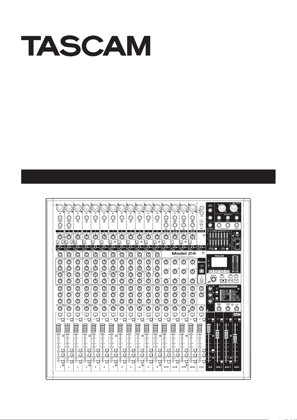
Top panel
2 – Names and Functions of Parts
a Analog input jack section
Use this section to connect the input jacks for each channel
and to adjust the input levels.
b Input channel mixing section
Use this section to choose input sources for each channel, adjust compressors and equalizers, and set levels sent to each
bus (MAIN MIX L/R, PFL/AFL L/R, MONITOR OUT 1/2, FX, SUB
L/R).
c Analog output jack section
Use this section to connect the output jacks and adjust the
output equalizer.
d Screen operation section
Use this section to operate the meter, home and MENU screens
shown on the display.
e Built-in effects operation section
Operate the built-in effects and adjust the output levels for
each output in this section.
f Analog output adjustment section
Adjust the output levels from the MAIN OUTPUT, SUB OUTPUT, OUTPUT MON 1 and OUTPUT MON 2 jacks in this sec-
tion.
TASCAM Model 24
13
Page 14
2 – Names and Functions of Parts
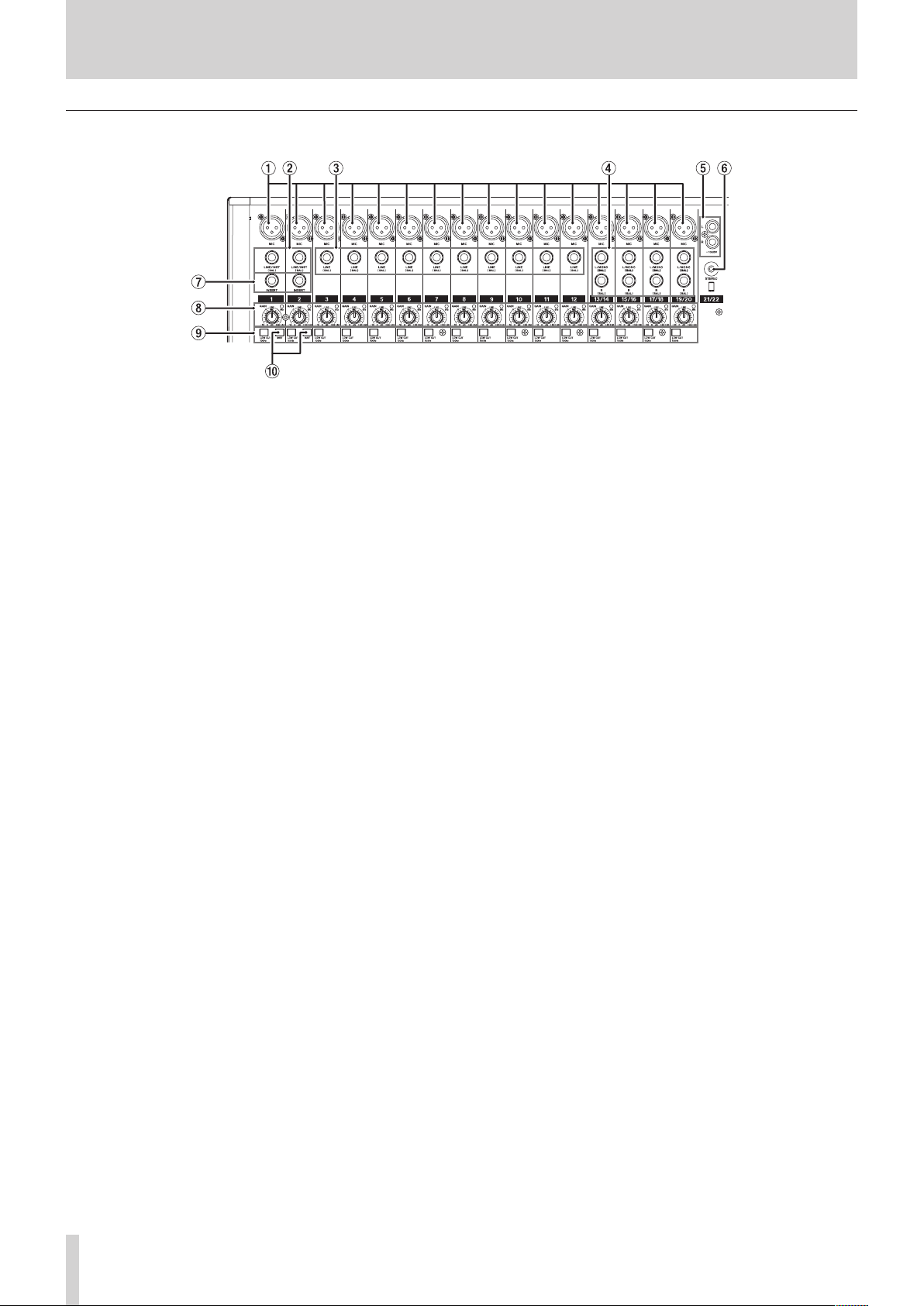
Analog input jack section
1 MIC input jacks (1-12, 13/14-19/20)
These are balanced XLR jacks for mic input.
o XLR (1: GND, 2: HOT, 3: COLD)
2 LINE/INST (BAL) mono input jacks (1-2)
These standard TRS jacks are mono line inputs.
When directly connecting a guitar, bass or other instrument,
set the INST switch to on (pushed in).
o TRS (Tip: HOT, Ring: COLD, Sleeve: GND)
3 LINE (BAL) input jacks (3-12)
These standard TRS jacks are line inputs.
o TRS (Tip: HOT, Ring: COLD, Sleeve: GND)
4 L/MONO (BAL)/R (BAL) stereo input jacks (13/14-
19/20)
These standard TRS jacks are stereo line inputs.
If only the L/MONO (BAL) jack in a pair is connected, the same
signal was be sent to both left and right channels.
o TRS (Tip: HOT, Ring: COLD, Sleeve: GND)
5 −10dBV (external input) jacks (21/22, RCA pin)
These RCA pin jacks are analog line outputs.
6 STEREO input jack (21/22, stereo mini)
This stereo mini jack is a line input jack.
Use this to connect with the line output jack of a tablet or oth-
er external device.
7 INSERT jacks (1-2, standard)
Use these standard TRS jacks to connect external devices (effects).
o TRS (Tip: SEND, Ring: RETURN, Sleeve: GND)
8 GAIN knobs and SIG indicators (1-12, 13/14-19/20)
Use the GAIN knobs to adjust the input levels of each channel.
its SIG indicator will light green when a signal is input (− 56dB
or higher).
If a SIG indicator stays lit red continuously, lower the GAIN
knob.
9 LOW CUT switches (1-12, 13/14-19/20)
Turn this switch on (pushed in) to enable low cut filters that
cut noise and other sounds at low frequencies.
0 INST switches (1-2)
Set according to the LINE/INST (BAL) input jack input sources.
Turn the INST switch on (pushed in) when connecting an gui-
tar, bass or other equipment with high output impedance.
Turn the INST switch off (not pushed in) when connecting
electronic instruments, audio devices, mics and other equip-
ment.
TASCAM Model 24
14
Page 15
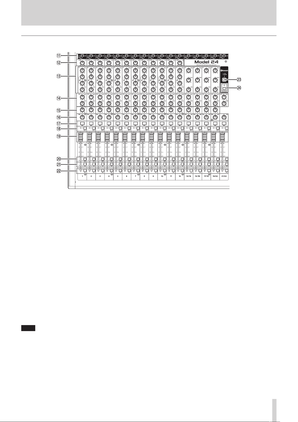
Input channel mixing section
2 – Names and Functions of Parts
q MODE switches (1-12, 13/14-19/20, 21/22)
Use these to select the input source for each channel. (See
“Setting the MODE switch” on page 29.)
w COMP knobs and indicators (1-12)
Use these knobs to adjust the compression of the signals input to each channel.
When compression is activated, the COMP indicators light.
e EQ knobs (1-12, 13/14-19/20)
i Use these to boost and attenuate the HIGH, MID and LOW
bands of each channel.
Setting range: ±15 dB
i The cutoff frequencies of the MID bands can be set for chan-
nels 1-12.
Setting range: 100Hz – 8kHz (default: 700Hz)
r MON 1/MON 2 knobs (1-12, 13/14-19/20, 21/22)
Use these to adjust the levels of signals sent to the MONITOR
OUT 1/2 buses.
t FX knobs (1-12, 13/14-19/20)
Use to adjust the levels of the signals sent to the FX bus.
y PAN knobs (1-12, 13/14-19/20, 21/22)
Use to adjust the stereo positions of the signals input to each
channel.
NOTE
i When PAN knobs are centered (C), signals are reduced by 3 dB
and sent to both left and right MAIN MIX L/R buses.
i When a PAN knob is turned all the way to the left (L), that
channel signal is sent only to the left MAIN MIX L/R bus. It is
not sent to the right bus.
i When a PAN knob is turned all the way to the right (R), that
channel signal is sent only to the right MAIN MIX L/R bus. It is
not sent to the left bus.
u REC buttons and indicators (1-12, 13/14-19/20,
21/22)
Use these to select the channels to record to the SD card.
i MUTE switches and indicators (1-12, 13/14-19/20,
21/22)
When these switches are on (pushed in, MUTE indicator lit),
those channels are muted.
o Channel faders (1-12, 13/14-19/20, 21/22)
Use these to adjust the send levels of channel signals.
p MAIN switches (1-12, 13/14-19/20, 21/22)
Turn these switches on (pushed in) to send channel signals to
the MAIN MIX L/R bus.
a SUB switches (1-12, 13/14-19/20, 21/22)
Turn these switches on (pushed in) to send channel signals to
the SUB L/R bus.
s PFL switches (1-12, 13/14-19/20, 21/22)
Turn these switches on (pushed in) to send channel signals to
the PFL/AFL L/R bus.
d ON/MUTE switches
Turn this switch “ON” to input audio from a paired Bluetooth
device.
f PAIRING button and indicator
Press and hold this button to activate Bluetooth pairing mode.
Press when pairing to end pairing mode. (See “Connecting
with Bluetooth devices” on page 23.)
TASCAM Model 24
15
Page 16
2 – Names and Functions of Parts
Analog output jack section
g MAIN OUTPUT L/R jacks
These analog outputs are XLR jacks.
o XLR (1: GND, 2: HOT, 3: COLD)
h SUB OUTPUT L/R jacks
These standard TRS jacks are analog outputs.
o TRS (Tip: HOT, Ring: COLD, Sleeve: GND)
j FOOTSWITCH jack
This standard TS jack is for connecting a footswitch.
o TS (Tip: HOT, Sleeve: GND)
NOTE
This unit was designed to be used with unlatched (momentary) footswitches that have to be pushed to function (shorted
when pushed).
k STEREO GRAPHIC EQ faders
This 7-band graphic equalizer affects signals output from the
MAIN OUTPUT and AUX OUTPUT MON 1/2 jacks.
l AUX OUTPUT MON 1/2 jacks
These standard TRS jacks are analog outputs.
o TRS (Tip: HOT, Ring: COLD, Sleeve: GND)
; FX OUTPUT jack
This standard TRS jack is an analog output.
When an external effect is connected, signals will not be sent
to the built-in effect.
When using an external effect, turn the built-in effect off.
o TRS (Tip: HOT, Ring: COLD, Sleeve: GND)
z CONTROL ROOM L/R jacks
These standard TRS jacks are analog outputs.
Use these to monitor signals from the MAIN MIX L/R bus or
PFL/AFL L/R bus.
o TRS (Tip: HOT, Ring: COLD, Sleeve: GND)
x PHONES jack
Use this standard stereo jack to connect stereo headphones.
Use an adapter to connect headphones with a mini plug.
Use this to monitor signals from the MAIN MIX L/R bus or PFL/
AFL L/R bus.
c PHANTOM +48V switch and indicator
Use this switch to supply +48V phantom power to the 1-2,
3-12 and 13/14-19/20 MIC input jacks on the top of the unit.
The indicator lights when the PHANTOM +48V switch is set to
on (pushed in). (See “Setting phantom power” on page 29.)
v SD card slot
Insert SD cards in these slots. (See “Inserting and removing SD
cards” on page 24.)
b MON 1/2/MAIN MIX switch
Set which output signals are affected by the equalizer.
MANI MIX: Equalizer is applied to signals sent from the
MAIN MIX L/R bus.
MON 1/2: Equalizer is applied to signals sent from the
MONITOR OUT 1/2 buses.
NOTE
Set the EQ IN/BYPASS switch to EQ IN also.
n EQ IN/BYPASS switch
When this switch is EQ IN, the equalizer will affect the output
signals set with the MON 1/2/MAIN MIX switch.
When BYPASS, the equalizer will not be applied regardless of
the MON 1/2/MAIN MIX switch setting.
Screen operation section
m Display
Shows a variety of information.
, USB indicator
This lights when the USB connection is working.
TASCAM Model 24
16
. PFL/AFL indicator
This indicator lights when either at least one channel PFL
switch is on (pushed in) or when the MON 1/MON 2 fader AFL
switch is on (pushed in).
/ Function buttons
The functions of these buttons change depending on the
screen shown on the display. The functions shown at the bot-
tom of the display are the currently assigned functions.
NOTE
For convenience, the four buttons under the display are called
the function buttons in this manual. From left to right, they are
called the F1, F2, F3 and F4 buttons.
Page 17
2 – Names and Functions of Parts
! MULTI JOG dial
This dial functions as a dial when turned and as a button when
pressed.
Dial functions
i Turn when the Home Screen is open to move the file play-
back position. (See “Locate function” on page 33.)
i When a MENU Screen is open, turn to select items and
change setting values. (See “Basic MENU screen operations”
on page 21.)
Button function
i Press when the Home Screen is open to designate a locate
point. (See “Locate function” on page 33.)
i When a Menu Screen is open, press to confirm selections
and settings (ENTER button function).
@ Output level indicators
These are output level indicators for the MAIN OUTPUT jacks.
# m/, buttons
i When stopped and during playback, press and hold these
buttons to search backward/forward.
i When the Home Screen is open, press the m button to lo-
cate to the beginning of the current song (00:00:00, which
is the zero point).
i When the Home Screen is open, press the , button to
locate to the end of the current song.
i If the current song has auto punch in or out points set, you
can also locate to those points.
i While pressing the 8 button, press the m button to lo-
cate to the point where recording last started.
i While pressing the 8 button, press the , button to lo-
cate to the point where recording last stopped.
i When the SD PLAY Screen is in playback state, press to skip
a file. (See “Playing WAV files on SD cards (SD PLAY mode)”
on page 39.)
$ MENU button
i When the Meter Screen is open, press to open the Home
Screen.
i When the MENU Screen or a menu item settings screen is
open, press to return to the Home Screen.
i When the Home Screen is open, press to open the MENU
Screen. (See “Menu structure” on page 20.) and (See “Basic MENU screen operations” on page 21.)
% 8 button/indicator
Press to stop playback or recording.
This button lights when stopped.
Press this button when paused to return to the beginning of
the song or file.
^ 7/9 button/indicator
Press this button to start playback.
This button lights during playback and recording.
This button blinks when paused.
& 0 button/indicator
Press this button to start recording.
This button lights during recording.
Press this button during playback to start recording (Manual
punch in).
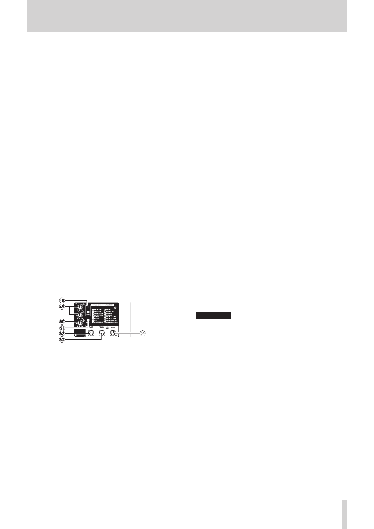
Built-in effects operation section
* MUTE switch/indicator
When the MUTE switch is on (pushed in, MUTE indicator lit),
the signal from the built-in effect is muted.
( TO MON 1/TO MON 2 knobs
Use these to adjust the levels of signals sent from the built-in
effects to the MONITOR OUT 1/2 buses.
) TO MAIN LR knob
Use these to adjust the levels of signals sent from the built-in
effects to the MAIN MIX L/R buses.
Q SELECT button
Open the EFFECT Screen and make built-in effect settings.
(See “Using the built-in effects” on page 31.)
The built-in effect return signal is return to the MAIN MIX L/R
bus and MONITOR OUT 1/2 buses.
W PFL/AFL MASTER knob
Use these to adjust the send level from the PFL/AFL L/R bus.
E CONTROL ROOM knob
Use to adjust the output levels of the CONTROL ROOM L/R
jacks.
R PHONES knob
Use this to adjust the headphone output level.
V
CAUTION
Before connecting headphones, minimize the volume with
the PHONES knob. Failure to do so could result in a sudden
loud noise that could harm hearing, for example.
TASCAM Model 24
17
Page 18

2 – Names and Functions of Parts
Analog output adjustment section
T MUTE switches and indicators (SUB, MON 1, MON 2,
MAIN)
When MUTE switches are on (pushed in, MUTE indicators lit),
signals to the corresponding output jacks are muted.
Y MAIN switch (SUB)
When this switch is on (pushed in), the SUB OUTPUT L/R jack
output signal is sent to the MAIN MIX L/R bus.
U AFL switches (MON 1/MON 2)
When these switches are on (pushed in), the AUX OUTPUT
MON 1/2 jack output signals are sent to the PFL/AFL L/R bus.
I SD MAIN MIX RETURN switch
When this switch is on (pushed in), playback of stereo master
files recorded on the SD card is output from the MAIN OUT-
PUT and AUX OUTPUT MON 1/2 jacks.
ATTENTION
Be aware that when this switch is on (pushed in), the sound of
the MAIN MIX L/R bus is not output.
O SUB fader
Use to adjust the output level of the SUB OUTPUT jacks.
P MON 1/MON 2 fader
Use to adjust the output levels of the AUX OUTPUT MON 1/2
jacks.
A MAIN fader
Use to adjust the output level of the MAIN OUTPUT jacks.
Rear panel
S USB port
This is a B-type USB port. Use a USB cable (Type-A to Type-B)
to connect the unit to a computer. (See “Connecting with a
Computer” on page 40.)
ATTENTION
The unit should be connected directly to the computer, not
through a USB hub. Moreover, noise could be picked up if the
cable is too long.
D AC IN connector
Connect the included power cord here.
F POWER switch
Press to turn the unit on and off.
V
CAUTION
Before turning the unit on, lower the volumes of connected
equipment to their minimum levels.
Failure to do so might cause sudden loud noises, which could
harm your hearing or result in other trouble.
NOTE
Do not do this when the unit is operating (including recording,
playing back or writing data to an SD card). Doing so could
cause proper recording to fail and recorded data to be lost.
TASCAM Model 24
18
Page 19

2 – Names and Functions of Parts
Home Screen
When the Meter Screen is open, press the MENU button to open
the Home Screen.
1 Repeat playback status
An icon appears when the repeat playback function is on. (See
“Repeat playback function” on page 33.)
2 Song format
This shows the current song file format.
44.1kHz, 16bit
44.1kHz, 24bit
48kHz, 16bit
48kHz, 24bit
NOTE
If no song is loaded, the operation format of the unit will be
shown like or .
3 Automatic punch in/out function on/off status
The icon appears when the automatic punch in/out
function is on. (See “Automatic punch in/out function” on
page 34.)
4 SD card present status
When an SD card is loaded, the icon appears.
When an SD card is protected, the icon appears.
Since system files cannot be updated when the icon ap-
pears, automatic punch in/out settings will not be retained
and previously loaded songs will not be loaded when the unit
is turned on again.
5 USB connection status
During USB connection, the icon appears.
6 Song name
This shows the name of the current song.
If a song is protected, an icon appears before the file name.
(See “Protecting/unprotecting songs” on page 28.)
7 Transport status
This icon shows the recorder operation status.
Indicator Meaning
8
9
0
7
8 Playback position
The current playback position is shown by a bar.
9 Automatic punch in/out point setting status
When the automatic punch in/out function is on, these show
the status of automatic punch in/out point setting.
Punch in point
Punch out point
Stopped at the beginning of the file
Paused
Recording
Playback
0 Remaining time
The remaining time available for recording on the SD card is
shown (in hours: minutes: seconds).
NOTE
The remaining recordable time on an SD card depends on the
number of recording channels and SD card capacity.
q Built-in effect on/off status
When the built-in effect is on, the icon appears. (See
“Using the built-in effects” on page 31.)
w Recorder time counter
This shows the elapsed time from the beginning of the song.
e Song length
This shows the length of the current song (in hours: minutes:
seconds).
r Function button functions
This shows the functions assigned to the function button on
the Home Screen.
i F1 button: This opens the Meter Screen.
i F2 button: This turns the repeat playback function
on/off.
i F3 button: This returns to the state before the previ-
ous operation.
i F3 button: This restores the state after the previous
operation.
i F4 button: This turns the built-in effect on/off.
NOTE
The F3 button and indicators appear when those
operations are possible.
Meters Screen
This shows the levels of the signals being input to the unit.
1 Transport status
This icon shows the recorder operation status.
2 Recorder time counter
This shows the elapsed time from the beginning of the song.
3 Track level meters
These show the signal levels of each channel.
4 Function button functions
This shows the functions assigned to the function button on
the Meter Screen.
i F1 Press to change the input sources shown on
the Meter Screen.
i F2 Press to show the level meters for channel
1–8 signals on the Meter Screen.
i F3 Press to show the level meters for channel
9–16 signals on the Meter Screen.
i F4 Press to show the level meters for channel
17–22 and MAIN MIX L/R bus signals on the
Meter Screen.
TASCAM Model 24
19
Page 20

2 – Names and Functions of Parts
Meter Screen details
When the Meter Screen is open, press the F4 button to
change the signal sources shown by the meters.
Channel input level screens
The levels of signals input on each channel are shown depending
on their MODE switch settings.
LIVE INPUT Screen
This shows the levels of signals being input to the input jacks.
MTR RETURN Screen
This shows the playback signal levels of songs recorded on SD
cards.
Channels that have recording data in the song
Channels that do not have recording data in the song
PC RETURN Screen
This shows the levels of signals output from a computer when
used as a USB audio interface.
Menu structure
When the Home Screen is open, press the MENU button to open
the MENU Screen.
The various menu items are as follows.
Menu item Function Page
SONG
TRACK CLEAR
AUTO PUNCH
A.PUNCH PRE ROLL
IMPORT
SD PLAY
STORAGE
SYSTEM Open the SYSTEM Screen
On the MENU Screen, select SYSTEM to open the SYSTEM Screen.
The menu items on the SYSTEM Screen are as follows.
Menu item Function Page
INFORMATION
DATE/TIME
SONG NAME
DISPLAY
FOOTSW
INITIALIZE
MEDIA FORMAT
NOTE
The settings for all menu items are retained even when the
unit is turned off.
Work with songs on an SD
card
Clear specific tracks or all
tracks
Set the auto punch in/out
function
Set the pre-roll point page 35
Import chosen WAV files to
song tracks
Play WAV files on an SD
card
SD cards can be accessed
from a computer
View SD card information,
song information and the
firmware version
Date and time settings page 25
Set the song name format page 37
Adjust the display page 25
Make footswitch settings page 34
Restore factory default
settings
Format the SD card page 38
page 26
page 36
page 34
page 36
page 39
page 40
See below
page 37
page 38
NOTE
Outputs from computers such as Windows Media Player and
iTunes are sent to channels 1-2.
TASCAM Model 24
20
Page 21

2 – Names and Functions of Parts
Basic MENU screen operations
After using the MENU button to open the MENU Screen, it can be
operated in the following manner.
This is an overview of basic operations. Function button assignments differ according to the screen shown on the display.
Selecting items (moving vertically on a
page):
Turn the MULTI JOG dial.
Opening a submenu from a page:
Press the MULTI JOG dial.
Confirming a selected item:
Press the MULTI JOG dial (ENTER button function).
Going back one step in a menu:
Press the F1 button.
Returning to the Home Screen from a MENU
Screen:
Press the F1 button.
Menu operation procedures
This explanation uses an example of setting the pre-roll point.
1. Press the MENU button to open the Home Screen.
2. Press the MENU button to open the MENU Screen.
NOTE
Press the F1 button to return to the Home Screen.
3. Turn the MULTI JOG dial to select the menu item.
A.PUNCH PRE ROLL selected
4. Press the MULTI JOG dial to open the settings screen.
A.PUNCH PRE ROLL Screen open
5. Turn the MULTI JOG dial to change the setting.
6. To set another item on the same screen, press the MULTI
JOG dial to move the cursor to the next setting.
7. Repeat steps 5 to 6 as necessary to set other items.
8. Press the F1 button to return to the MENU Screen.
TASCAM Model 24
21
Page 22

3 – Preparation
Connecting other equipment
This is an example of Model 24 connections.
Precautions before making connections
0 Carefully read the operation manuals of the devices to be connected and then connect them correctly.
0 Before making connections, turn this unit and all equipment to be connected off (standby).
0 Install all connected devices, including this unit, so that they are powered from the same line. When using a power strip or similar de-
vice, be sure to use one that has high current capacity (thick cable) in order to minimize fluctuations in power voltage.
0 Before connecting audio equipment, set the following knobs and faders to their lowest values. Failure to do so could cause sudden loud
noises from monitoring equipment, and this could damage the equipment or harm hearing.
o GAIN knobs (channels 1-12, 13/14-19/20)
o Channel faders (channels 1-12, 13/14-19/20, 21/22)
o SUB fader
o MON 1/MON 2 faders
o MAIN fader
o CONTROL ROOM knob
o PHONES knob
TASCAM Model 24
22
Examples of connections to a Model 24
Page 23

3 – Preparation
Connecting microphones
Dynamic mics
Connect to MIC input jacks.
Condenser mics
When using a condenser microphone that requires phantom
power, connect it to a MIC input jack and then turn the PHAN-
TOM +48V switch on (pushed in). (See “Setting phantom
power” on page 29.)
The PHANTOM +48V indicator lights when the PHANTOM
+48V switch is on (pushed in).
Guitars
When connecting a guitar or bass directly to this unit, use the
LINE/INST (BAL) jacks on channels 1-2 and turn the INST switch
on (pushed in) for that jack.
Connecting electronic devices and other audio equipment
Use the following inputs to connect electronic devices and other
audio equipment.
o LINE/INST (BAL) input jacks*
o LINE (BAL) input jacks
o L/MONO (BAL)/R (BAL) input jacks
o −10dBV input jacks
o STEREO input jack
* When an INST switch is on (pushed in), input through the
LINE/INST (BAL) input jack will be unbalanced.
Connecting monitor speakers
Connect monitor speakers (powered speakers or an amplifier and
speaker system) to the CONTROL ROOM L/R jacks.
Depending on the PFL switch and AFL switch settings, signals
from the MAIN MIX L/R bus and PFL/AFL L/R bus can be monitored
Use the CONTROL ROOM knob to adjust the speaker volume.
Connecting headphones
Connect headphones to the PHONES jack (standard stereo).
Depending on the PFL switch and AFL switch settings, signals
from the MAIN MIX L/R bus and PFL/AFL L/R bus can be monitored
V
CAUTION
Before connecting headphones, minimize the volume with
the PHONES knob. Failure to do so could result in a sudden
loud noise that could harm hearing, for example.
Connecting with Bluetooth devices
This unit can input sound from a computer, portable audio device or other equipment that supports Bluetooth (A2DP).
Pairing
Follow the procedures below to enable communication with a
Bluetooth device.
NOTE
Pairing also requires operation of the Bluetooth device.
Refer to the operation manual of the Bluetooth device for pro-
cedures.
1. Press the ON/MUTE switch to set it to ON.
2. Confirm that the PAIRING indicator on this unit is blinking. If
it is unlit, press the PAIRING button.
NOTE
When the unit is turned on, it automatically becomes ready for
pairing. If 2 minutes pass in pairing mode, it will end. Press this
button to reactivate pairing mode when it is disabled.
3. Select “Model 24” (this unit) on the other Bluetooth device.
When pairing succeeds, the PAIRING indicator will stop
blinking and remain lit, and connection with the other device will be complete.
NOTE
i Some older Bluetooth devices require the input of a passkey.
Enter “0000” in such cases.
i Pairing will automatically end if connection is not confirmed
within two minutes.
i When this unit is turned on, it will automatically try to con-
nect with the Bluetooth device to which it was previously con-
nected. At this time, pairing will automatically end after five
minutes if connection is not possible because that Bluetooth
device is not turned on or its Bluetooth function is turned off.
Unpairing
The Bluetooth device that is currently connected can be unpaired
from the unit.
1. Press and hold the PAIRING button for at least two seconds.
2. This ends the pairing. The PAIRING indicator will start blink-
ing and the unit will be ready to pair.
Computer connections
Use a commercially-available Type-A-Type-B USB cable to connect the unit to a computer USB 2.0 port.
When the USB connection is working, the USB indicator in the
screen operation section lights.
ATTENTION
The unit should be connected directly with the computer instead of via a USB hub. Moreover, noise could be picked up if
the cable is too long.
TASCAM Model 24
23
Page 24

3 – Preparation
Inserting and removing SD cards
Inserting SD cards
Insert an SD card into an SD card slot on the top of the unit to
enable playback and recording by this unit.
NOTE
SD cards can be inserted whether or not the unit is on or off.
1. Open the SD card slot cover.
2. The SD card should be inserted with its label facing left.
3. Close the SD card slot cover.
Removing SD cards
Turn the unit off or stop operation before removing an SD card.
V
CAUTION
Never remove an SD card when the unit is operating (including recording, playing back, or writing data to the SD card).
Doing so could cause proper recording to fail, data to be lost,
and sudden loud noises from monitoring equipment, which
might damage the equipment, harm hearing or cause other
trouble.
Before turning the power on
1. Make the following settings on the top of the unit.
o Other knobs w all the way left
o Faders w all the way down
o Switches w off (not pushed in)
2. Minimize the output levels of audio sources and input levels
of amplifiers connected to this unit.
Turning the power on
1. Use the POWER switch on the back of the unit to turn its
power on.
Startup screen
1. Press the SD card in gently to make it to come up.
2. Pull the SD card out.
SD card write protection switches
SD cards have write-protection switches that prevent writing
new data to them.
If you slide the write-protection switch to the “LOCK” position,
writing will not be possible. Move the write-protection switch to
the unlocked position in order to record, erase and otherwise edit
data on the card.
Turning the power on and off
V
CAUTION
i Turn down the volume of the sound system connected to the
unit before starting up or shutting down the unit.
i Do not wear connected headphones when turning the unit
on and off. Loud noises could damage the speakers or harm
your hearing.
Meter Screen
After the unit starts and the Startup Screen is shown, the Meter Screen will open.
NOTE
After the unit is turned on, the PAIRING indicator will blink for
a set amount of time.
2. Turn connected input audio source devices on.
3. Finally turn amplifiers on.
Turning the power off
Follow the procedures above in reverse when turning the power
off.
Failure to follow the correct order could result in clicking noises,
for example, that might damage equipment.
V
CAUTION
Do not disconnect the power cord when the unit is operating
(including recording, playing back, or writing data to an SD
card). Doing so could cause proper recording to fail, record-
ed data to be lost, and sudden loud noises from monitoring
equipment, which might damage the equipment, harm hear-
ing or cause other trouble.
NOTE
When the unit is started up for the first time (or when the
built-in clock is reset after being left unused without power for
a long time), the DATE/TIME Screen appears before the Start-
up Screen to allow the date and time of the built-in clock to
be set. (See “Setting the built-in clock date and time” on page
25.)
TASCAM Model 24
24
Page 25

3 – Preparation
Setting the built-in clock date and time
Using its internal clock, this unit includes the date and time when
a file is recorded.
1. On the SYSTEM Screen, select DATE/TIME to open the DATE/
TIME Screen. (See “Menu operation procedures” on page
21.)
2. Turn the MULTI JOG dial to change a value, and press the
MULTI JOG dial to confirm it and move the cursor to the next
item.
NOTE
Use the F2 and F3 buttons to move the cursor.
3. Change the year, month, day, hour and minute in order, and
complete the date and time setting.
4. Press the F4 button to confirm the setting and return
to the SYSTEM Screen.
NOTE
i When making a setting, you can press the F1 button to
cancel the changes and return to the SYSTEM Screen.
i When setting the time, the time display will be stopped.
i By setting the TYPE item to “DATE” on the SONG NAME Screen,
the date and time set here can be used for song names. (See
“Setting the song name format” on page 37.)
Adjusting the display
The display contrast and brightness can be adjusted.
Adjusting the display contrast
1. On the SYSTEM Screen, select DISPLAY to open the DISPLAY
Screen. (See “Menu operation procedures” on page 21.)
2. Select CONTRAST, and press the MULTI JOG dial.
3. Adjust the display contrast.
Options: 10–40 (default: 26)
4. Press the MULTI JOG dial to confirm the setting.
5. Press the F1 button to return to the MENU Screen.
Adjusting the display brightness
1. On the SYSTEM Screen, select DISPLAY to open the DISPLAY
Screen. (See “Menu operation procedures” on page 21.)
2. Select DIMMER, and press the MULTI JOG dial.
3. Adjust the display brightness.
Options: HIGH (default), LOW
4. Press the MULTI JOG dial to confirm the setting.
5. Press the F1 button to return to the MENU Screen.
Preparing an SD card for use
In order to make an SD card usable in this unit, whether for recording or playback, this unit must be used to create a system
file on it first.
ATTENTION
In order to record, this unit must be used to format it first. (See
“Formatting SD cards” on page 38.)
1. “No sys file. Make sys file. Are you sure?” appears
in a pop up when a new card or a card formatted by another
device is inserted into the unit.
2. Press the MULTI JOG dial to create a system file.
When system file creation is complete, the Home Screen will
reopen.
TASCAM Model 24
25
Page 26

4 – Managing Songs
This recorder treats each recording data group as one song and
manages data by song.
For one song, WAV files are saved for 22 tracks and a stereo master file.
To record or produce music, a song that has already been created
needs to be loaded or a new song needs to be created.
This chapter describes functions that range from basic operations
such as procedures for loading songs and creating new songs to
various song management functions.
NOTE
The maximum recording time for a single song is 23:59:59.
Viewing the song list
To open a list of songs saved on an SD card, select SONG on the
MENU Screen, and press the MULTI JOG dial to open the SONG
Screen. (See “Menu operation procedures” on page 21.)
On the SONG Screen, the following functions are assigned to the
function buttons.
0 Press the F1 button to return to the MENU Screen.
0 Press the F2 button to show the date on the SONG
Screen.
0 Press the F3 button to show the size on the SONG Screen.
0 Press the F4 button to open the NEW Screen where you
can create a new song. (See “Creating a New Song” on page
26.)
Song Operation
Select the desired song file on the SONG Screen and press the
MULTI JOG dial to open a pop-up menu list with possible song
operations.
Creating a New Song
To record or play with this unit, you must create and load a song.
The following procedure can be used to create a new song.
1. Open the SONG Screen when the recorder is stopped. (See
“Menu operation procedures” on page 21.)
2. Press the F4 button to open the NEW Screen.
3. Turn the MULTI JOG dial to select the recording file format.
Options: 44.1kHz - 16bit (default), 44.1kHz - 24bit,
48kHz - 16bit, 48kHz - 24bit
4. Edit the name of the song as necessary.
To edit the name of the song, press the F2 button to
open the NAME EDIT Screen.
For details about how to edit song names, see “Editing text”
on page 28.
TIP
The song name can also be edited later using the RENAME
Screen.
5. Press the F4 button to save the currently loaded song
and create a new song.
When song creation completes, the SONG Screen reopens.
NOTE
i To cancel song creation, press the F1 button.
i A maximum of 100 songs can be created on a single SD card.
i Songs are created in the MTR folder on the SD card.
To use a song operation, turn the MULTI JOG dial to select the
desired item, and press the MULTI JOG dial.
LOAD
Loads the selected song.
INFORMATION
View information about the selected song.
DELETE
Deletes the selected song.
PROTECT
Protect the selected song.
UNPROTECT
Stop protection of the selected song.
RENAME
Edits the name of the selected song.
TASCAM Model 24
26
Page 27

4 – Managing Songs
Loading Songs
Use the following procedure to load the song you want.
1. Open the SONG Screen when the recorder is stopped. (See
“Menu operation procedures” on page 21.)
NOTE
The * icon appears for a song currently being loaded. An
icon will appear before protected songs.
2. Select the song that you want to load and press the MULTI
JOG dial to open the menu list pop-up.
3. Select LOAD, and press the MULTI JOG dial.
After the selected song loads, the SONG Screen will reopen.
Viewing song information
You can check the song name (title), sampling frequency, bit rate,
size, and date and time last written.
1. Open the SONG Screen when the recorder is stopped. (See
“Menu operation procedures” on page 21.)
2. Select the song with information that you want to check and
press the MULTI JOG dial to open the menu list pop-up.
3. Select INFORMATION, and press the MULTI JOG dial.
The INFORMATION Screen will open.
Deleting songs
You can delete songs.
Deleting unnecessary songs when the SD card space is low can
create more open space.
1. Open the SONG Screen when the recorder is stopped. (See
“Menu operation procedures” on page 21.)
2. Select the song that you want to delete and press the MULTI
JOG dial to open the menu list pop-up.
3. Select DELETE, and press the MULTI JOG dial.
The DELETE Screen will open.
4. Press the F4 button to confirm deletion.
When song deletion completes, the SONG Screen reopens.
ATTENTION
Deleted songs cannot be restored.
NOTE
i To cancel song deletion, press the F1 button.
i The current song cannot be deleted. To delete the current
song, load another song first.
The song name, sampling frequency, bit rate, size, date and
time last written will be shown.
4. After checking, press the F1 button to return to the
SONG Screen.
TASCAM Model 24
27
Page 28

4 – Managing Songs
Protecting/unprotecting songs
By protecting a song, you can disable editing, recording and deletion operations for that song.
You can protect and stop protecting songs.
1. Open the SONG Screen when the recorder is stopped. (See
“Menu operation procedures” on page 21.)
2. Select the song that you want to protect or unprotect and
press the MULTI JOG dial to open the menu list pop-up.
3. Select PROTECT or UNPROTECT, and press the MULTI JOG dial.
The PROTECT or UNPROTECT screen will open.
4. Pres the F4 button to protect or unprotect the song.
NOTE
To cancel protection or unprotection, press the F1 but-
ton.
5. When song protection completes, the SONG Screen reopens.
NOTE
i icons appear before songs that are protected in the song list
shown for copying, deletion and other operations.
i If you try to execute a prohibited operation (editing, record-
ing, deletion) on a protected song, “Song is protected.” will
appear in a pop-up message on the display.
Editing song names
1. Open the SONG Screen when the recorder is stopped. (See
“Menu operation procedures” on page 21.)
2. Select the song with name that you want to change and
press the MULTI JOG dial to open the menu list pop-up.
3. Select RENAME, and press the MULTI JOG dial.
The RENAME Screen will open.
4. Edit the song name.
For details about how to edit song names, see “Editing text”
below.
NOTE
To cancel song name editing, press the F1 button.
5. When finished editing the song name, press the F4
button to confirm the song name.
When song name editing is complete, the SONG Screen re-
opens.
Editing text
Use these operations to edit text.
Changing the cursor (editing point) position
Use the F2 and F3 buttons.
You can also press the MULTI JOG dial to move to the next
character.
Deleting the character at the cursor position:
Turn the MULTI JOG dial.
You can input up to 11 characters, including symbols, num-
bers, and uppercase and lowercase letters.
Leaving a single space open:
Turn the MULTI JOG dial to select a blank space at the left end
of any row, and press the MULTI JOG dial.
Canceling edits:
Press the F1 button.
Confirming the changes:
Press the F4 button.
TASCAM Model 24
28
Page 29

5 – Basic recording
Selecting the input source
This unit has 22 inputs (22 line/16 mic inputs) with separate MIC
and standard jacks.
The LINE/INST (BAL) input jacks on channels 1–2 support high
impedance input, including direct guitar input.
Turn the INST switch on (pushed in) when connecting an guitar
or similar instrument directly.
ATTENTION
Do not connect to both the MIC jack and the standard input
jack (LINE/INST (BAL), LINE (BAL), L/MONO (BAL) or R (BAL))
on a channel at the same time.
TIP
Set the INST switch to off (not pushed in) when connecting
an electric-acoustic guitar with a built-in preamp or an active
electric guitar, as well as when an effect is connected between
an guitar and this unit.
Setting the MODE switch
Using the MODE switch settings of each channel to select their
input sources individually.
LIVE: Use the signal from the input jack as the input source.
PC: Use a signal from a computer connected to the USB
port as the input source.
MTR: Use a playback signal from the SD card as an input
source.
When a MODE switch is set to “MTR”, the signal from the input
jack on that channel will be recorded.
This function is useful when recording and playing back repeatedly because the monitored sound is automatically switched according to the recording or playback status.
Sounds on channels when in MTR mode
Transport status REC button off REC button on
Stop Muted
Playing back
Recording
Playback sound
only
Playback sound
only
Sound from input
jack
Playback sound
only + sound from
input jack
Sound from input
jack
Setting phantom power
When connecting a condenser mic that requires phantom power,
press the PHANTOM +48V switch when the recorder is stopped
to turn phantom power on/off.
When phantom power is on, the PHANTOM +48V indicator
lights, and phantom power is supplied to the MIC input jacks (1-
12, 13/14-19/20).
V
CAUTION
Set the following knobs and faders to their minimum values
before changing the PHANTOM +48V switch on/off setting.
Depending on the connected mics, sudden loud noises from
monitoring equipment could occur, and this could damage
the equipment or harm hearing.
• GAIN knobs
• Channel faders
• SUB fader
• MON 1/MON 2 faders
• MAIN fader
• CONTROL ROOM knob
• PHONES knob
ATTENTION
i Before connecting condenser mics, turn this unit and all
equipment to be connected off (standby).
i The PHANTOM +48V switch turns it on/off for the input chan-
nels (1-12, 13/14-19/20) simultaneously. Do not turn the
PHANTOM +48V switch on (pushed in) when connecting a
mic that does not require phantom power.
i Do not connect or disconnect mics when the PHANTOM
+48V switch is on (pushed in). Doing so could cause a loud
noise and might damage this unit and connected equipment.
i Turn the PHANTOM +48V switch on (pushed in) only when
using a condenser microphone that requires phantom power.
Turning the PHANTOM +48V switch on (pushed in) when a
dynamic mic or other mic that does not require it is connected
could damage this unit and connected equipment.
i When using condenser mics that require phantom power
and dynamic mics together, be sure to use balanced dynamic
mics. Unbalanced dynamic mics cannot be used when phantom power is enabled.
i Supplying phantom power to some ribbon mics could break
them. If you are unsure, do not supply phantom power to a
ribbon mic.
Monitoring
Monitoring is important when recording and mastering.
With this unit, monitoring is possible using an external monitor-
ing system (powered monitor speakers or an amp and speakers)
or using stereo headphones.
Use the CONTROL ROOM and PHONES knobs to adjust the level
of the monitoring system.
TASCAM Model 24
29
Page 30

5 – Basic recording
SIG indicators and level meters
The channel 1-12, 13/14-19/20 SIG indicators and level meters
shown on the Meter Screen can be used to check the levels of this
unit’s audio signals.
The level meters are for visually checking signal levels and can
also be used to check whether or not signals are being input
to this unit. For example, even when you cannot hear anything
monitoring,
If the Meter Screen level meters are moving, signals are being input to this unit.
The SIG indicators light green when signals (of at least −56 dB)
are input through their channels.
If a SIG indicator lights red, the input source signal is too loud or
the GAIN knob is turned up too far.
If the SIG indicator lights red even when the GAIN knob is turned
all the way to the left, the input source signal is to loud. Lower its
volume.
Track level meters (1-12, 13/14-21/22)
The show track playback signal or truck input signal levels.
Channels for which the MODE switch is set to “MTR” will show the
following signal levels according to the operation status.
REC button
Unlit PLAY Track playback signal
Blinking
(recording standby)
Blinking
(recording)
NOTE
When the playback signal is shown, the level of the recorded
signal on the track is being shown, so the levels of the level
meters cannot be changed.
When the input signal is shown, adjusting channel 1-12, 13/14-
19/20 GAIN knobs will change the levels of the level meters.
MAIN MIX L/R level meters (MAIN)
These show the MAIN MIX L/R bus levels.
Transport
status
PLAY
Stop Track input signal
Record Track input signal
Level meter display
Playback signal
Track input + playback
signal
Recording
This unit can simultaneously record up to 24 tracks, including 22
channel inputs and the MAIN MIX L/R bus.
The following recording operations assume that mics, guitars and
other things to record have been connected to the unit, input signals have been assigned as track recording sources, monitoring
equipment has been connected and a song has been loaded.
1. Press the REC buttons for channel to record.
Press the REC button to start recording standby. It will blink
red.
When a MODE switch is set to “MTR”, the signal from the input jack on that channel will be recorded. (See “Setting the
MODE switch” on page 29.)
NOTE
i The MAIN MIX L/R bus does not have a REC button, but it is
always in recording standby. The signals of the MAIN MIX L/R
bus will always be recorded if the 0 button is pressed.
i When the REC buttons of tracks that already have recordings
is blinking, press them to make them unlit.
2. Set the recording levels.
Use the GAIN knobs of each channel to adjust their input
levels.
Watch the SIG indicators above and to the right of the GAIN
knobs, and set the levels suitably.
At the same time, check that the sound heard through headphones or a monitoring system is not distorted and that an
unintended effect has not been set.
NOTE
If an input is too loud, the SIG indicator will light red.
If the SIG indicator lights red even when its GAIN knob is
turned all the way to the left, lower the volume of the input
source.
3. Press the 0 button.
Recording will start and the 0 and 7/9 buttons will light.
The REC buttons for tracks to record will stop blinking and
stay lit.
4. When recording has completed, press the 8 button.
5. Use the m/, buttons and 8 button, for example to lo-
cate to a position you want to check.
TIP
For details about the locate function, see “Locate function” on
page 33.
6. Press the 7/9 button to play the recorded tracks.
Use the channel and MAIN faders to adjust the playback levels.
Use the volume of the monitoring system to adjust the final
monitoring level.
Use the PAN knobs of each channel to set the position of
each track signal between left and right speakers.
TASCAM Model 24
30
NOTE
i The channel PAN knobs and channel faders control the play-
back output signals of already recorded tracks or the monitoring volume of input signals. They do not control signals to be
recorded.
i If you are not satisfied with a recording, repeat the above pro-
cedure from the beginning.
Page 31

5 – Basic recording
Undoing operations
If you make a mistake operating the unit or want to do a recording over, for example,the operation last conducted can be undone. Editing, recording and other operations can be undone.
The following types of operations can be undone.
0 Recording operations
0 Auto punch in/out operations
0 Track clearing operations
If a song is loaded or the unit is turned off, Information used for
undoing and redoing will be lost, so undoing and redoing previous operations will no longer be possible.
NOTE
Files used for undoing are saved on the SD card. If you want to
delete those files to make more space on the ST card, reload
the current song on the SONG Screen.
Undoing the previous operation
1. When the Home Screen is open, press the F3 button.
Using the built-in effects
This unit has built in effects, so you can apply effects without an
external effect device.
Channels 1-12 and 13/14-19/20 can have an effect applied. Their
signals are sent to the built-in effect by the FX bus.
The return signal is returned to the MAIN MIX L/R and MONITOR
OUT 1/2 buses.
1. Use the FX knobs of each channel to adjust the levels of sig-
nals sent to the FX bus.
2. Use the EFFECT Screen to select the type of effect. (See “Set-
ting the built-in effect” on page 31.)
3. Use the TO MAIN LR and TO MON 1/TO MON 2 knobs to
adjust the return levels for the MAIN MIX L/R and MONITOR
OUT 1/2 buses.
4. When the AFL switch is on (pushed in), use the CONTROL
ROOM/PHONES knob to adjust the return level.
NOTE
The sound with the effect applied can be monitored from the
CONTROL ROOM L/R jacks or PHONES jack.
Setting the built-in effect
1. Press the SELECT button to open the EFFECT Screen.
The following confirmation pop-up message will appear.
2. Press the F4 button to return to the state before the
previous operation.
NOTE
To cancel undoing, press the F1 button.
Redoing an undone operation
1. After undoing, when the “ ” appears on the Home
Screen, press the F3 button.
The following confirmation pop-up message will appear.
2. Press the F4 button to restore the previous operation
and return to the state before undoing.
2. Select TYPE, and press the MULTI JOG dial.
3. Set the built in effect type.
Options: 1.SMALL HALL (default), 2.LARGE HALL,
3.SMALL ROOM, 4.LARGE ROOM,
5.PLATE, 6.STUDIO,
7.LIVE, 8.SHORT DELAY,
9.DELAY, 10.PING PONG,
11.CHORUS, 12.FLANGER,
13.DELAY+SHALL, 14.DELAY+LHALL,
15.CHORUS+SHALL, 16.CHORUS+LHALL
NOTE
To cancel redoing, press the F1 button.
TASCAM Model 24
31
Page 32

5 – Basic recording
4. Select PARAMETER, and adjust the amount of the set effect.
You can check the effect as you change it.
Options: 1 (default), 100
NOTE
Press the F4 button to set the currently selected TYPE
item PARAMETER item value to its default.
5. Press the F3 button to turn the built-in effect on.
The CURRENT STATUS will change from OFF to ON.
NOTE
Press the F2 button to turn the built-in effect off.
6. Press the F1 button to return to the Home Screen.
TASCAM Model 24
32
Page 33

6 – Recorder functions
Locate function
When the Home Screen is open, you can use the MULTI JOG dial
to set the locate point.
On the Home Screen, the current position of the recorder is
shown as a time in hours (h), minutes (m) and seconds (s).
By setting the time in this display area, you can change the current position of the recorder.
Changing the playback position
When the Home Screen is open and the recorder is stopped or
playing back, you can use the MULTI JOG dial to set the locate
point.
Using the direct locate function to locate
1. When the Home Screen is open and the recorder is stopped,
press the MULTI JOG dial to enable direct locate mode. A
cursor will appear at the location to be changed in the recorder counter.
2. Press the REC button for the track with the part to be re-
placed to enter recording standby (REC button blinks).
NOTE
i Set the punch in and out points at least one second apart.
i Punch in recording is not possible when the REC button is on
for eight or more channels.
3. Start playback before the part to be replaced.
4. When the part to be replaced is reached, press the 0 but-
ton, and perform the part.
Recording will start (punch in).
5. When the end of the part to be replaced is reached, press
the 8 button.
The unit will switch to playback and then stop after two sec-
onds.
Using the footswitch to punch in/out
By connecting the recommended TASCAM RC-1F footswitch
(sold separately) to the FOOTSWITCH jack on the top of the unit,
you can use it to punch in/out.
To use a footswitch to punch in/out, you must set the foot switch
function assignment to “PUNCH IN/OUT” in advance. (See “Setting
up the footswitch” on page 34.)
2. Turn the MULTI JOG dial to change a value, and press the
MULTI JOG dial to confirm it and move the cursor to the next
item.
3. Change the seconds, minutes and hours in that order to
move to that time as the current recorder position.
4. Press the 7/9 button to start playback or the 0 button to
start recording from that position.
Repeat playback function
The repeat playback function can be used to play something over
and over.
When the Home Screen is open, press the F2 button to set
the repeat playback function.
Nothing shown: The current song will keep playing regardless
of whether the area is recorded or not.
: The current song will play and then stop.
: The current song will play repeatedly.
Punch in/out function
Punching in and out is a technique used to replace parts of already recorded tracks.
You can start playback of a recording, switch to recording when it
reaches the part to be replaced (punch in), and then switch back
to playback when the end of that part is reached (punch out) and
stop after two seconds.
1. Determine the part you want to replace in advance.
Select a point where the replacement audio can be combined well with the original track audio.
At step 4 above, press the footswitch instead of the 0 button,
and at step 5 press it again instead of the 8 button.
TASCAM
RC-1F
NOTE
This unit was designed to be used with unlatched (momentary) footswitches that have to be pushed to function (shorted
when pushed).
TASCAM Model 24
33
Page 34

6 – Recorder functions
Setting up the footswitch
Use the FOOTSW Screen to set the footswitch.
1. Open the FOOTSW Screen when the recorder is stopped. (See
“Menu operation procedures” on page 21.)
2. Turn the MULTI JOG dial to select the function to assign to
the footswitch.
Option Meaning
PLAY / PAUSE
(default)
PUNCH IN / OUT
FX MUTE
Press to start playback when stopped
or paused. Press to pause when playing.
Press during playback to punch in.
Press when recording to punch out.
Mute the built-in effect signal.
3. Press the MULTI JOG dial to confirm the assigned function.
A * appears next to the selected function.
4. Press the F1 button to return to the MENU Screen.
Setting the footswitch polarity
The setting of this unit can be changed according to the polarity
of the footswitch being used.
Select “NORMALLY OPEN” or “NORMALLY CLOSE” so that the actual
footswitch movement matches that shown by the illustration on
the screen.
NOTE
When using a TASCAM RC-1F, set the POLARITY switch to N.
OPEN.
Automatic punch in/out function
Using the automatic punch in/out function, you can automatically record between punch in and out points set in advance.
To use the automatic punch in/out functions, start playback from
a pre-roll point before the punch in point where recording will
start.
Recording will stop when the punch out point is reached, but
playback will continue for two seconds before stopping.
Setting the punch in/out points
1. Open the AUTO PUNCH Screen when the recorder is stopped.
(See “Menu operation procedures” on page 21.)
2. Press the 7/9 button to start playback.
3. Press the MULTI JOG dial to set the punch in and out points.
The set points are shown next to the IN and OUT items.
NOTE
i You can also turn the MULTI JOG dial to set the points.
i Set the punch in and out points at least one second apart.
i Press the F2 button to clear set punch in and out points.
i Press the F3 button to select either the punch in or out
point. An * will appear next to the selected item.
4. Press the 8 button to stop playback.
5. Press the F4 button to turn the automatic punch in/
out function on.
The icon appears on the AUTO PUNCH Screen.
1. Open the FOOTSW Screen when the recorder is stopped. (See
“Menu operation procedures” on page 21.)
2. Press the F4 button to open the POLARITY Screen, and
turn the MULTI JOG dial to set the footswitch polarity.
Options: NORMALLY OPEN (default), NORMALLY CLOSE
3. Press the F1 button to return to the FOOTSW Screen.
TASCAM Model 24
34
6. Press the F1 button to return to the MENU Screen.
TIP
i By setting only the punch in point, you can start recording
with automatic punch in and then continue recording until
you press the 8 button to stop.
i By setting only the punch out point, you can start recording
by pressing the 0 button and then stop recording with automatic punch out.
Page 35

6 – Recorder functions
Setting a pre roll point
When using automatic punch in, the amount of playback time
before the punch in point can be set (pre roll point).
1. Select A.PUNCH PRE ROLL on the MENU screen to open the
A.PUNCH PRE ROLL screen. (See “Menu operation proce-
dures” on page 21.)
2. Set the pre-roll point.
Option Meaning
Do not locate to a point before the
OFF
1sec. – 10sec.
(default: 2sec.)
punch in point. Manually moving to
somewhere before the punch in point
beforehand will be necessary.
Locate to a pre roll point the set time
before the punch in point and start
playback.
3. Press the F1 button to return to the MENU Screen.
Rehearsing punching in and out
You can rehearse before punch in/out recording. In rehearsal,
recording will not occur, but monitoring will be the same as if
recording.
1. Press the MENU button when the recorder is stopped to
open the Home Screen.
Confirm that the icon appears on the Home Screen.
Using automatic punching in and out
Follow these procedures to punch in and out automatically and
record.
1. Confirm that the icon appears on the Home Screen.
2. Press the REC buttons for the tracks you want to record us-
ing automatic punch in/out.
NOTE
Punch in recording is not possible when the REC button is on
for eight or more channels.
3. Press the 0 button.
o The transport starts playback from the pre-roll point.
Both track playback and input source signals can be
monitored. (See “Setting a pre roll point” on page 35.)
o When the punch in point is reached, only the input
source signal will be monitored. The 0 button will light.
o When the punch out point is reached, both track play-
back and input source signals will be monitored. The 0
button will become unlit.
o Playback will automatically stop two seconds after the
punch out point. The 7/9 button will blink.
2. Press the REC buttons for the tracks you want to record us-
ing automatic punch in/out.
NOTE
Punch in recording is not possible when the REC button is on
for eight or more channels.
3. Press the 7/9 button.
Auto punch in/out rehearsal starts.
o The transport starts playback from the pre-roll point.
Both track playback and input source signals can be
monitored. (See “Setting a pre roll point” on page 35.)
o When the punch in point is reached, only the input
source signal will be monitored. The 0 button will blink
showing that it is rehearsal mode.
o When the punch out point is reached, both track play-
back and input source signals will be monitored. The 0
button will become unlit.
o Playback will automatically stop two seconds after the
punch out point. The 7/9 button will blink.
Rehearsal can be repeated.
TASCAM Model 24
35
Page 36

7 – Track editing
Clearing tracks
The selected track will be cleared.
1. Open the TRACK CLEAR Screen when the recorder is stopped.
(See “Menu operation procedures” on page 21.)
2. Turn the MULTI JOG dial to select the track to clear, and
press the MULTI JOG dial.
A confirmation message will appear.
NOTE
Press the F2 button to open a message confirming that
you want to clear all tracks.
4. Open the TRACK IMPORT Screen when the recorder is
stopped. (See “Menu operation procedures” on page 21.)
WAV files in the MUSIC folder will be shown.
5. Select a WAV file to import.
o Turn the MULTI JOG dial to select a WAV file.
o Press the MULTI JOG dial when a folder is selected to
show its contents.
o Press the F1 button to return to the MENU Screen.
o Press the F2 button to move up one level.
6. Press the F4 button.
On the TRACK IMPORT Screen, the name of the file to be imported and the TARGET TRACK(S) item with the names of
open tracks are shown.
3. Press the F4 button to clear the track(s).
NOTE
i To cancel clearing tracks, press the F1 button.
i Undoing is possible only for the last cleared track.
4. After clearing tracks completes, the TRACK CLEAR Screen will
reopen.
Importing tracks
You can import audio files that you have to tracks in the current
song.
Files that can be imported to tracks must be WAV (BWF) format
(“.WAV” extension).
To import an audio file with a different format (.mp3, etc.) to this
unit, it must be converted to a WAV file that matches the format
of the song it will be imported into beforehand.
1. Connect this unit with a computer. (See “Connecting with a
Computer” on page 40.)
2. Use the computer to copy WAV files on it to this unit’s MUSIC
folder.
3. Follow the proper disconnection procedures on the comput-
er before disconnecting the USB cable. (See “Disconnecting”
on page 40.)
NOTE
i If there are no openings for tracks to import, an “Import error.
No track” pop-up message will appear.
i To cancel importing a track, press the F1 button.
i Importing is not possible under the following conditions.
• Not enough open space is available on the SD card
• There are no empty tracks
• The characteristics (sampling frequency or bit rate) of the
WAV file you are trying to import differ from the current
song.
Example: Trying to import a 48kHz WAV file when the cur-
rent song is 44.1kHz
i If there is no file that can be imported, a “No File” pop-up
message will appear.
i If the imported WAV file is stereo, selection will be of two con-
secutive tracks. It cannot be put into a single mono track.
7. Select the track to import, and press the F4 button to
import it.
8. When importing completes, the TRACK IMPORT Screen re-
opens.
TASCAM Model 24
36
Page 37

8 – Settings and Information
Viewing information
Use the INFORMATION screen to view various types of information about the unit. Follow the procedures below to view the INFORMATION screen.
1. On the SYSTEM Screen, select INFORMATION to open the Infor-
mation Screen. (See “Menu operation procedures” on page
21.)
The Information Screen has 3 pages. The CARD page opens
first.
2. Turn the MULTI JOG dial to cycle through the CARD, SONG and
FIRMWARE screens.
CARD Screen
Shows the use status of the currently loaded SD card
SONG Screen
Shows the number of songs on the loaded SD card
FIRMWARE Screen
Shows the unit’s system firmware version.
3. Press the F1 button to return to the MENU Screen.
CARD Screen
The CARD Screen shows the status of the currently loaded SD
card.
FIRMWARE Screen
The FIRMWARE Screen shows the firmware version.
VERSION
This shows the system firmware version of this unit.
Setting the song name format
Set the name format is used by the unit for creative songs.
1. On the SYSTEM Screen, select SONG NAME to open the SONG
NAME Screen. (See “Menu operation procedures” on page
21.)
2. Set the file name format.
Option Meaning
DATE (default)
WORD
Use the date for the song name.
(Example: 180101_0001)
Use the 6-character song name set on
the EDIT screen.
(Example: TASCAM_0001)
TOTAL SIZE
Shows the total amount of space on the SD card.
USED SIZE
Shows the amount of space used on the SD card.
REMAIN SIZE
Shows the amount of space unused on the SD card.
SONG Screen
The SONG Screen shows the use status of the MTR folder.
TOTAL SONG
This shows the total number of songs in the MTR folder.
NOTE
The date is set using the unit’s internal clock. (See “Setting the
built-in clock date and time” on page 25.)
Setting the WORD item
To set the characters, select WORD on the TYPE Screen. An EDIT
item will appear on the SONG NAME Screen that can open the WORD
EDIT Screen.
For details about how to set characters, see “Editing text” on page
28.
TASCAM Model 24
37
Page 38

8 – Settings and Information
Restoring factory default settings
You can restore the various settings stored in the memory of the
unit to their factory default values.
Use the following menu procedures to do so.
1. On the SYSTEM Screen, select INITIALIZE to open the INI-
TIALIZE Screen. (See “Menu operation procedures” on page
21.)
2. Press the F4 button to restore the factory default set-
tings.
3. When the setting completes, the SYSTEM Screen will reopen.
NOTE
i Press the F1 button to cancel execution.
i The date and time setting is not initialized.
Formatting SD cards
Formatting erases all music files on the SD card and automatically creates new MTR, MUSIC and UTILITY folders as well as a
tascam_m.sys file.
3. Press the F4 button to start formatting.
4. When formatting is complete, the SYSTEM Screen will reopen.
NOTE
The writing speeds to SD cards and other storage media that
use flash memory tend to decrease after writing occurs repeatedly.
If the writing speed decreases, this could have a negative impact on recording.
Using the ERASE function of this unit should restore the writing speed of the SD card.*
For this reason, we recommend using the ERASE function at
the following times.
o Whenever the card has been written to until it became
completely full
o On a regular schedule (about once per month)
o Before starting important recordings
* Writing speed might not be restored depending on the SD
card condition (including malfunction and age).
ATTENTION
i Formatting an SD card erases all the data on it. This cannot be
undone.
i Always use this unit to format media to be used with it. Opera-
tion of this unit might be affected when using an SD card that
has been formatted by a computer or other device.
1. On the SYSTEM Screen, select MEDIA FORMAT to open the ME-
DIA FORMAT Screen. (See “Menu operation procedures” on
page 21.)
QUICK: Execute quick formatting.
ERASE (Recommendation): Erase and format the card.
2. Select the format method, and press the MULTI JOG dial.
A confirmation message will appear on the QUICK or ERASE
Screen.
Shown when QUICK selected
NOTE
Press the F1 button to cancel formatting and return to
the previous screen.
TASCAM Model 24
38
Page 39

8 – Settings and Information
Playing WAV files on SD cards (SD PLAY mode)
The WAV files in the MUSIC folder on an SD card can be played
back. (See “Loading WAV files from a computer” on page 41.)
The following audio file formats can be played back in SD PLAY
mode.
WAV: 44.1/48kHz, 16/24-bit
BWF: 44.1/48kHz, 16/24-bit
NOTE
Playback signal is sent from channels 21 and 22.
1. Set the channel 21/22 MODE switch to “MTR”.
2. Set the channel 21/22 MON 1/MON 2 and BAL knobs and
the channel fader to their middle positions
3. Open the SD PLAY Screen when the recorder is stopped. (See
“Menu operation procedures” on page 21.)
4. Select a file to play back
o Turn the MULTI JOG dial to select a WAV file.
o Press the MULTI JOG dial when a folder is selected to
show its contents.
o Press the F1 button to return to the MENU Screen.
o Press the F2 button to move up one level.
6. Press the F1 button twice to return to the MENU
Screen.
NOTE
Only WAV files can be played back. Unsupported files will not
be shown.
5. Press the F4 button or 7/9 button to start WAV file
playback.
The SD PLAY Screen will show playback status.
o Press the F1 button to return to the file selection
screen.
o Press the F2 button to turn the repeat playback
function on and select the repeat playback mode.
Display Meaning
The folder that contains the currently
No indicator
playing WAV file will play back, and
then playback will stop.
The currently playing WAV file will play
back repeatedly.
The folder that contains the currently
playing WAV file will play back repeatedly.
o Press the F3 (<<) button to skip to the beginning of the
WAV file. Press near the beginning of the WAV file to skip
to the beginning of the track before it.
o Press the F4 (>>) button to skip to the beginning of the
next WAV file.
TASCAM Model 24
39
Page 40

9 –Using a computer to transfer data
By connecting this unit with a computer using a commercially-available USB cable, you can back up song data on the SD card
in the unit to the computer, as well restore backed up song data
to the unit. You can also export track and stereo master files from
songs to the computer and import audio files from the computer.
Backed up data can be restored to other Model 24 units. Since
this allows you to freely move files between Model 24 units, you
can easily conduct additional recording or mixing at different locations.
ATTENTION
You can conduct the same operations by removing the SD
card from the unit and connecting it directly to a computer
or by using a card reader instead of using USB to connect the
unit and the computer. Turn the unit’s power off or stop operation before removing the SD card.
This unit can transfer the following data to a computer.
Entire songs
This unit can transfer all the data for a song from the MTR folder
to a computer. This operation is called “backing up”. Data backed
up to a computer can also be transferred to the MTR folder, and
restored as a song file. This operation is called “restoring”.
ATTENTION
Do not change names, delete or otherwise alter individual
files inside the MTR folder. Doing so could prevent loading
data as a song and make proper recording and playback operations impossible.
3. To connect with the computer, press the F4 button.
The unit enters USB storage mode and connects with the
computer.
Make sure that the SD card is inserted properly.
4. This unit appears on the computer as an external drive
named “TASCAM_M” (if the card was formatted by this unit).
NOTE
Follow these procedures to open This PC.
Windows 10
Left-click the Windows Start button, and from Windows
System select PC.
Windows 8.1
Left-click the Windows Start button, click the down arrow
icon on the Start screen, and select This PC under Windows
System in the application list.
Windows 7
Left-click the Windows Start button, and select Computer
in the Start menu.
5. Click the TASCAM_M drive on the computer to show the
MTR, MUSIC and UTILITY folders.
WAV files
By placing WAV files from the computer into the MUSIC folder,
you can import them to song tracks. Moreover, WAV files in the
MUSIC folder can be played back in SD PLAY mode.
Connecting with a Computer
You cannot use this unit’s recording, playback and other recorder
functions when it is connected to a computer by USB.
To connect with a computer, use a Type-A to Type-B USB2.0 cable
to connect the USB port on the back of this unit to a USB port on
the computer.
The USB cable can be connected either before or after turning
this unit on.
1. Use a USB cable (Type-A to Type-B) to connect the computer
to this unit’s USB port.
ATTENTION
The unit should be connected directly with the computer instead of via a USB hub. Moreover, noise could be picked up if
the cable is too long.
2. On the MENU Screen, select STORAGE to open the STORAGE
Screen. (See “Menu operation procedures” on page 21.)
ATTENTION
i This unit receives power through its power cord. It cannot be
powered by USB.
i Do not disconnect the power cord or turn off the power
during data transfer. Data will be lost if the power is interrupted during transfer. Lost data cannot be restored.
i Do not change the names of folders in TASCAM_M.
NOTE
i Do not change names, delete or otherwise alter individual
files inside the MTR folder.
i The UTILITY folder is used when updating the unit system, for
example.
6. Press the F1 button to return to the Meter Screen.
Disconnecting
Before disconnecting the USB cable, use the proper procedures
for your computer to unmount the unit (as an external drive).
See the computer’s operation manual for instructions about how
to unmount an external volume.
Press the F1 button to disconnect from the computer and
return to the Home Screen.
TASCAM Model 24
40
Page 41

9 –Using a computer to transfer data
Loading WAV files from a computer
1. Use a USB cable (Type-A to Type-B) to connect the computer
to this unit’s USB port. (See “Connecting with a Computer”
on page 40.)
2. Click the “Model 24” drive on the computer to show the MTR,
MUSIC and UTILITY folders.
3. Drag and drop files on the computer that you want to trans-
fer to the unit to the MUSIC folder.
ATTENTION
i The UTILITY folder is used when updating the unit system, for
example.
i Do not change names, delete or otherwise alter individual
files inside the MTR folder. Doing so could prevent loading
data as a song and make proper recording and playback operations impossible.
TIP
i You can manage the content of MTR or MUSIC folders from
the computer.
i You can create subfolders in the MUSIC folder up to the sec-
ond level for use with this unit. The Model 24 cannot recognize sub-folders and files located at the third layer level or below. The unit cannot recognize subfolders and audio files on
the third level or below.
TASCAM Model 24
41
Page 42

10 – USB audio interface functions
Installing the dedicated software (Windows only)
To use this unit as a USB audio interface with a Windows computer, dedicated software must be installed on the computer.
Download the latest software from the TEAC Global Site (http://
teac-global.com/).
Installing the dedicated software will install a driver and a Settings Panel application.
ATTENTION
i Before starting to install software, quit other applications.
i With a Mac, the standard OS driver will be used, so there is no
need to install any software.
Installing the Windows dedicated software
Follow the procedures below to install the Windows dedicated
software.
ATTENTION
i Complete installation of the Windows dedicated software on
the computer before connecting the unit to it with the USB
cable.
i If you connected the unit to the computer using the USB ca-
ble before installing the Windows dedicated software and the
“Found New Hardware Wizard” launched, close the Wizard
and disconnect the USB cable.
6. Next, click the Install button.
7. Next, click the Install button to start installation. (Windows
7 only)
8. The following screen appears when installation has com-
pleted. The following screen appears when installation has
completed.
Click the Finish button.
Windows dedicated software installation
procedures
1. Download the latest Windows dedicated software from the
TEAC Global Site (http://teac-global.com/) and save it on
the computer to be used with the unit.
2. Uncompress the saved software (zip file) on the computer
desktop or another location.
3. Double-click the “TASCAM_Model_Mixer_Installer_x.xx.exe”
file in the folder that appears after uncompression to launch
the installation software.
ATTENTION
If you open a zip file without decompressing it and double-click the “TASCAM_Model_Mixer_Installer_x.xx.exe” file in
the folder that opens, installation will not start. Right-click the
zip file and select “Extract All”, for example, to decompress it
and then try again.
4. When a Security Warning or User Account Control screen ap-
pears, click the Yes button.
5. Read the contents of the User License Agreement, and select
“I accept the agreement” if you agree to the terms. Then, click
the Next > button.
The installer will quit and the Windows Settings Panel will
launch.
NOTE
The first time you connect the unit by USB to the computer after installing the software, installation of the device driver will
be executed. Some time might be necessary before the unit
is recognized because Windows Update will be automatically
searched at this time. If the unit is still not recognized after a
while, open the software installation screen from the notification area at the bottom right of the computer display, and
click “Skip obtaining driver software from Windows Update” to
stop the search.
TASCAM Model 24
42
Page 43

10 – USB audio interface functions
Uninstalling the Windows dedicated software
Uninstalling from the Programs and Features Control Panel
NOTE
Normally, there is no need to uninstall the dedicated software.
Follow these procedures if a problem occurs or you no longer
intend to use the unit with the computer.
1. From the Start menu, open the Control Panel and launch
Programs and Features.
NOTE
i In Windows 10, right-click the Start button and click Control
Panel when it appears.
i In Windows 8.1, click the button that appears at the bot-
tom left of the Start screen to open the Apps screen, and click
Control Panel.
2. If View by: is set to Category, click Uninstall a program under
the Program item.
If View by: is set to Large icons or Small icons, click Programs
and Features.
3. Select “TASCAM Model_Mixer x.xx” from the list, and dou-
ble-click it.
4. Then, follow the instructions that appear on the screen.
Opening the Settings Panel (Windows only)
Open the Settings Panel in the following manner.
Windows 10
0 Click the Windows Start button and select All Programs w
TASCAM w ModelMixer Settings Panel.
Windows 8.1
0 Right-click the Windows Start button and select Control Panel.
NOTE
You can also left-click the Start button to open the Start
Screen. Click the button to open the Apps screen, and select
ModelMixer Settings Panel under TASCAM.
Windows 7
0 Click the Windows Start button and select All Programs w
TASCAM w ModelMixer Settings Panel.
Windows Settings Panel overview
1 Status display area
This shows the current status of the software.
Item displayed Meaning
Software Ver This is the software version.
Firmware Ver
Device
Sample Rate
2 Buffer Size
You can adjust the size of the buffer used to handle the audio
input and output signals transferred to and from the computer.
Smaller buffer sizes result in less audio signal delay (latency),
but require high-speed processing by the computer.
If the processing cannot keep up, for example, due to other
system operations, clicking and popping noises might occur
and the audio signal might even drop out.
Increasing the buffer size will stabilize operation and suppress
negative effects on audio signals, but the delay in audio signals sent to the computer will increase.
You can use the slider on the panel to adjust the buffer size for
this unit according to the use conditions.
Options
64, 128, 256 (default), 512,1024, 2048
This is the firmware version used by the
connected unit.
This is the name of the connected unit.
(No Device is shown when no device is
connected.)
This shows the sampling frequency of
the current song.
If an SD card is not loaded, this shows
the sampling frequency set by the
computer.
TASCAM Model 24
43
Page 44

10 – USB audio interface functions
Setting Sound Properties
1. Open the OS Control Panel.
NOTE
Follow these procedures to open the Control Panel.
Windows 10
Left-click the Windows Start button, and from Windows
System select Control Panel.
Windows 8.1
Right-click the Windows Start button, and select Control
Panel.
Windows 7
Left-click the Windows Start button, and select Control
Panel in the Start menu.
2. Double-click Sound in the Control Panel.
NOTE
If the Control Panel is set to be viewed as icons, a Sound icon
will appear.
3. On the Playback page, right-click Model 24, and click Set as
Default Device in the pop-up menu that appears.
When you do this, the green check mark appears next to the
selected device.
Simultaneous ASIO/WDM playback
The driver for this unit can simultaneously play ASIO output from
a DAW and WDM output from Windows Media Player, for example. The sample rates of both sources must be set to the same
value for simultaneous playback to be possible. Moreover, the
sample rate must also be set to the same value for both playback
and recording in the Windows Sound Properties.
When the sample rates are the same
Example: Windows (WDM) at 44100 Hz, ASIO at 44100 Hz
The Windows audio and ASIO sound are mixed and played simultaneously.
When the sample rates are different
Example: Windows (WDM) at 48000 Hz, ASIO at 44100 Hz
Only sound from a DAW and other ASIO sources are output.
Sound from Windows Media Player and other WDM sources
are not output.
When the DAW is shut down, for example, and output from
ASIO sources stops, sound from Windows Media Player and
other WDM sources will become audible.
Windows 7 screen
NOTE
Set the default device according to the ASIO device being
used on the Recording tab in the same manner as on the Play-
back tab.
4. After completing the setting, click the OK button.
5. Launch Windows Media Player and start playback to input
the playback sound from the computer to channels 1 and 2
on the Model 24. (MODE switches: PC)
NOTE
i If you change the setting while Windows Media Player is run-
ning, the software will not recognize that the device has been
changed. In this case, restart Windows Media Player.
i If you still cannot hear sound after making the settings and
completing the procedures above, restart the computer.
i If you make this setting, sound will be output through this
unit, but no sound will be output from the computer’s speakers or headphone jack.
TASCAM Model 24
44
Page 45

11 – Messages
The following is a list of messages that appear in pop-up windows.
Refer to this list if one of these pop-up messages appears on the Model 24 and you want to check the meaning or determine a proper
response.
Message Meaning and response
Card Error
Card Full
Dup File Name
File Not Found
No sys file
Make sys file
Song Protected
Invalid Card
Change Card
I/O Too Short
MBR error
Init card
No Card
Non-supported
Card Protected
USB Fs mismatch
Current Song
Invalid I/O point
Write error
REC continue
REC stop
Card slow
Need to set
I/O point.
Sample rate
Unmatch
Bit length
Unmatch
Remain time is
not enough
8 track
punch in limit
Song is not
loaded
Song number full
SD PLAY:
cannot record
SD CARD cluster
size error
Import error.
No track
Already protected
The SD card cannot be recognized properly. Replace the SD card.
The SD card has no remaining capacity. Erase unnecessary files or transfer them to a computer.
A file with the same name already exists. Change the file name.
The file cannot be found or the file may be damaged. Check the relevant file.
The system file is missing. This unit requires a system file for operation.
When this message appears, press the MULTI JOG dial to create a system file.
This operation is not possible because the song is protected. Remove protection.
Something might be wrong with the SD card. Change the SD card.
The time between the punch in and out points is too short. Set them with at least 1 second between
them.
The SD card is not formatted properly or the card is broken.
Change the SD card or press the MULTI JOG button while this message is being shown to format the card.
Formatting will erase all the data on the SD card.
A SD card is not set.
Insert a recordable SD card.
The file format is not supported. Please see “Playing WAV files on SD cards (SD PLAY mode)” on page 39
for file formats that this unit can use.
The SD card is write-protected. Disable SD card write-protection.
The sampling rate of the current song and the USB audio interface are not the same.
Change the sampling rate of one so that they are the same.
The current song cannot be deleted. To delete the current song, load another song first.
The punch in/out point settings on the AUTO PUNCH Screen are not set correctly.
Automatic punching in/out occurred at an invalid position for the punch in or out point.
Start the automatic punch operation from a valid point.
Writing to the SD card timed out. This has caused audio to be interrupted and noise to occur.
Writing to the SD card timed out, and recording stopped.
SD card writing performance has become worse.
Execute the erase format function or change the SD card.
Neither the punch in or out points are set for the automatic punch in/out function.
Either the punch in or out point must be set.
The sampling frequency of the WAV file to be imported does not match the current song.
Select a WAV file with the same sampling frequency as the current song or convert the sampling frequen-
cy before importing.
The bit rate of the WAV file to be imported does not match the current song.
Select a WAV file with the same bit rate as the current song or convert the bit rate before importing.
The SD card does not have enough open space, so importing is not possible.
Erase unnecessary files or transfer them to a computer.
The maximum number of tracks for punch in recording is eight.
Press REC buttons to reduce the number of recording tracks to eight or less.
No song is loaded.
Create a new song or load a song.
The maximum number of songs that can be created on an SD card is 100.
Erase unnecessary songs.
SD PLAY mode is for playback only.
Recording is not possible.
Recording is not possible because the SD card cluster size is not right.
Back up the contents of the SD card on a computer and then format it with this unit.
Then, restore the data from the computer.
Importing is not possible because there are no open tracks.
Use TRACK CLEAR to clear a track. (See “Clearing tracks” on page 36.)
The selected song is already protected.
TASCAM Model 24
45
Page 46

11 – Messages
Message Meaning and response
Already unprotected
Can't Save Data
Device Error
File Error
Not Continued
Player Error
UNDO not available
Writing Failed
Sys Rom Err
System Err XX
(XX is a number.)
The selected song is already unprotected.
If any of these errors occurs, turn the unit off and restart it.
If these error messages continue to appear frequently, please contact the store where you purchased this
unit or TASCAM customer support.
TASCAM Model 24
46
Page 47

12 – Troubleshooting
If you are having trouble with the operation of this unit, please try the following before seeking repair.
If these measures do not solve the problem, please contact the store where you bought the unit or TEAC customer support (see the back
cover).
The unit will not turn on.
0 Confirm that the power plug and other connectors are insert-
ed completely.
The SD card is not recognized.
0 Confirm that the SD card is inserted completely.
No sound is output
0 Are the input sources and MODE switches set properly?
0 Are that channel faders raised to suitable levels?
0 Is the MAIN fader raised to a suitable level?
0 Is a monitoring system correctly connected to the PHONES
jack or CONTROL ROOM L/R jacks?
Is the monitoring system set up correctly?
0 Is the PHONES knob or CONTROL ROOM knob place to a suit-
able level?
0 Is the SD MAIN MIX RETURN switch on (pushed in, during play-
back of anything other than a stereo master file)?
The sound I want to record is distorted
0 Are the channel GAIN knobs set too high?
Are the input source levels to high?
0 Is the EQ set too high?
0 Are any channel faders or the MAIN fader raised too high?
0 Is the monitoring level too high, causing the monitoring sys-
tem to distort?
Noise occurs when a passive guitar or bass is
connected directly
0 Connecting another device to the unit’s SUB OUTPUT jacks
(stereo output) could reduce noise.
0 It could be affected by interference noise from another de-
vice, for example. If a power amplifier or other device with a
large transformer, or a fluorescent light, for example, is near-
by, changing the distance or orientation of such devices could
reduce noise.
Playback is not possible.
0 If you are trying to play a WAV file, confirm that it uses a sam-
pling frequency (44.1/48 kHz) and a bit depth (16/24-bit) that
are supported by this unit.
Sound via Bluetooth breaks up or is noisy.
0 Are there any wireless LAN devices, other Bluetooth devices,
microwave ovens or similar equipment nearby?
Keep such devices as far away as possible during use.
0 Try reducing the distance between this unit and the other
Bluetooth device. Try changing the positions of this unit and
the other Bluetooth device.
0 The operation of apps other than for music playback on the
smartphone could cause the sound to break up. In this case,
stop operation of apps other than the one used for music
playback.
Cannot connect or communication is interrupted when using Bluetooth.
0 Confirm that the other Bluetooth device power is on and that
its Bluetooth function is on.
0 Confirm that the other Bluetooth device is not too far away.
Are there walls or other obstacles, for example, between this
unit and the other Bluetooth device?
Try changing the positions of this unit and the other Blue-
tooth device.
0 Turn OFF and restart the Model 24.
0 Remove the “Model 24” pairing record from the other Blue-
tooth device, and try pairing the unit with that Bluetooth de-
vice again. (See “Connecting with Bluetooth devices” on page
23.)
Cannot pair with another Bluetooth device.
0 Confirm that the other Bluetooth device supports A2DP.
0 Confirm that the other Bluetooth device is in a state that al-
lows transmission. For details, check the operation manual of
that Bluetooth device.
0 Turn the power off for both this unit and the other Bluetooth
device once, turn them both on again and try pairing them.
0 Turn off Bluetooth devices other than the one that you are try-
ing to pair with.
0 Remove the “Model 24” pairing record from the other Blue-
tooth device, and try pairing the unit with that Bluetooth de-
vice again. (See “Connecting with Bluetooth devices” on page
23.)
There is noise.
0 Confirm that the connection cables do not have contact is-
sues.
TASCAM Model 24
47
Page 48

12 – Troubleshooting
A computer does not recognize the unit
when connected by USB.
0 Has the dedicated software been installed? (See “Installing the
dedicated software (Windows only)” on page 42.)
0 This unit cannot be used with USB 1.1. Use a USB 2.0 or USB
3.0 port.
0 Do not use a USB hub with this unit. Always connect the unit
directly to a USB port on the computer.
0 If the above methods do not resolve the problem, connect the
unit to a different USB port on the computer.
When connected by USB, sound breaks up or
noise occurs.
0 The processing load on the computer causes sound to break
up and noise to occur.
0 If a wireless LAN or background software, including antivirus
software, is running, turn it off during use of this unit. In addition, please use “computer’s power option“ as ”high perfor-
mance setting“.
0 Use the shortest USB cable possible.
0 Use a USB port built into the computer because the computer
USB port affects the USB connection.
TASCAM Model 24
48
Page 49

13 – Specifications
General
Supported media
SD cards (Class 10 or more)
SDHC cards (Class 10 or more)
SDXC cards (Class 10 or more)
File System
SD card: FAT16
SDHC card: FAT32
SDXC card: exFAT
Recording file formats
WAV (BWF): 44.1/48kHz, 16/24-bit (Maximum file size: 2 GB)
Playback file formats
WAV (BWF): 44.1/48kHz, 16/24-bit
Recordable Channel
Max. 24 channels (22ch + 2 stereo mix)
Inputs and outputs
Analog audio input and output ratings
MIC input jacks (1-12, 13, 15, 17, 19)
Connectors: XLR-3-31 (1: GND, 2: HOT, 3: COLD)
Maximum input level: +10 dBu
Nominal input level: -8 dBu
Minimum input level: -58 dBu
Gain adjustment range: 0 - 50 dB
Input impedance: 1.8 kΩ
LINE/INST (BAL) input jacks (1-2)
Connectors: 6.3mm (1/4”) standard TRS jacks
(Tip: HOT, Ring: COLD, Sleeve: GND)
Maximum input level: +22 dBu
Nominal input level: +4 dBu
Gain adjustment range: -0 - +40 dB
Input impedance: 22 kΩ (LINE)/1 MΩ (INST)
LINE (BAL) input jacks (3-12)
Connectors: 6.3mm (1/4”) standard TRS jacks
(Tip: HOT, Ring: COLD, Sleeve: GND)
Maximum input level: +22 dBu
Nominal input level: +4 dBu
Gain adjustment range: -0 - +40 dB
Input impedance: 22 kΩ
L/MONO (BAL) / R (BAL) input jacks
(13/14-19/20)
Connectors: 6.3mm (1/4”) standard TRS jacks
(Tip: HOT, Ring: COLD, Sleeve: GND)
Maximum input level: +22 dBu
Nominal input level: +4 dBu
Gain adjustment range: -20 - +30 dB
Input impedance: 22 kΩ
INSERT jacks (1-2)
Connectors: 6.3mm (1/4”) standard TRS jacks
(Tip: HOT, Ring: COLD, Sleeve: GND)
RETURN (Ring)
Nominal input level: 0 dBu
Maximum input level: +18 dBu
Input impedance: 10 kΩ
SEND (Tip)
Nominal input level: 0 dBu
Maximum input level: +18 dBu
Input impedance: 100 Ω
−10dBV input jack (21/22)
Connectors: RCA pin jacks
Maximum input level: +8 dBV
Nominal input level: -10 dBV
Input impedance: 10 kΩ
STEREOinput jacks (21/22)
Connector: 3.5m stereo mini jack
Maximum input level: +8 dBV
Nominal input level: -10 dBV
Input impedance: 10 kΩ
MAIN OUTPUT connectors
Connectors: XLR-3-32 (1: GND, 2: HOT, 3: COLD)
Rated output level: +4 dBu
Maximum output level: +22 dBu
Output impedance: 100 Ω
SUB OUTPUT connectors
Connectors: 6.3mm (1/4”) standard TRS jacks
(Tip: HOT, Ring: COLD, Sleeve: GND)
Rated output level: -2 dBu
Maximum output level: +16 dBu
Output impedance: 100 Ω
MON 1 / MON 2 AUX OUTPUT connectors
Connectors: 6.3mm (1/4”) standard TRS jacks
(Tip: HOT, Ring: COLD, Sleeve: GND)
Rated output level: -2 dBu
Maximum output level: +16 dBu
Output impedance: 100 Ω
FX AUX OUTPUT connectors
Connectors: 6.3mm (1/4”) standard TS jacks
(Tip: HOT, Sleeve: GND)
Rated output level: -2 dBu
Maximum output level: +16 dBu
Output impedance: 100 Ω
CONTROL ROOM L/R connectors
Connectors: 6.3mm (1/4”) standard TRS jacks
(Tip: HOT, Ring: COLD, Sleeve: GND)
Rated output level: -2 dBu
Maximum output level: +16 dBu
Output impedance: 100 Ω
PHONES jack
Connectors: 6.3mm (1/4”) standard stereo jack
Maximum output: 80mW + 80mW (32Ω load)
TASCAM Model 24
49
Page 50

13 – Specifications
Control input/output
FOOTSWITCH jack
Connectors: 6.3mm (1/4”) standard TS jacks (Tip: HOT, Sleeve:
GND, Unlatch type correspondence)
USB port
Connector: 4-pin USB B-type
Protocol: USB 2.0 HIGH SPEED (480 Mbps)
Computer system requirements
Check the TEAC Global Site (http://teac-global.com/) for the latest information about supported operating systems.
Windows
Supported operating systems
Windows 10 32-bit
Windows 10 64-bit
Windows 8.1 32-bit
Windows 8.1 64-bit
Windows 7 32-bit SP1 or later
Windows 7 64-bit SP1 or later
(Windows 8, Windows Vista and Windows XP are not support-
ed)
Computer hardware requirements
Windows computer with a USB 2.0 port
CPU/processor speed
2 GHz or faster dual core processor (x86)
Memory
2 GB or more
ATTENTION
Operation of this unit was confirmed using standard computers that meet the above requirements. This does not
guarantee operation with all computers that meet the above
requirements. Even computers that meet the same system requirements might have processing capabilities that differ according to their settings and other operating conditions.
Mac
Supported operating systems
macOS High Sierra (10.13 or later)
macOS Sierra (10.12 or later)
OS X El Capitan (10.11 or later)
Supported audio drivers
Windows
ASIO2.0, WDM
Mac
Core Audio
Audio performance
Noise
Residual output noise (22kHz, A-weighted)
MAIN MIX OFF: -100 dBu
MAIN MIX -0dB, 1ch-0dB: -80 dBu
Equivalent input noise (EIN)
-128 dBu (Rs=150 Ω, MIC IN w INSERT SEND, gain knob at
MAX, A-weighted)
Total harmonic distortion ratio (THD+N)
(gain knob at MIN, 1kHz)
MIC IN w MAIN OUT: 0.01% or less
MIC IN w MAIN OUT: 0.004% @+4dBu
Frequency response
(All GAIN knobs minimized, 1 kHz)
20Hz to 30kHz (+0.5/–1.0dB: Analog)
20Hz to 20kHz (+0.5/–1.0dB: Digital)
Crosstalk
(PAN knobs turned completely left or right, 1 kHz)
Between channels: -80 dB
Between input and output: -80 dB
Maximum gain
(All GAIN knobs maximized, PAN knobs turned completely
left or right, EQ knobs and STEREO GRAPHIC EQ faders at
middle positions)
MIC w MAIN OUT: 74 dB
MIC w INSERT OUT: 54 dB
MIC w SUB OUT: 74 dB
MIC w CONTROL ROOM OUT: 79 dB
MIC w MONITOR OUT: 75 dB
MIC w FX OUT: 75 dB
USB/SD w MAIN OUT: 24 dB
Phantom Power
+48V
Computer hardware requirements
Mac with a USB 2.0 port
CPU/processor speed
2 GHz or faster dual core processor
Memory
2 GB or more
TASCAM Model 24
50
Page 51

Bluetooth
Bluetooth version: 4.0
Output class: 2 (about 10m* unobstructed transmission dis-
tance)
Supported profiles: A2DP
Supported A2DP codecs: SBC, AAC
Supported A2DP content protection: SCMS-T
* The transmission distance is only an estimate and might vary
depending on the surrounding environment and radio wave
conditions.
Other
Power
AC100-240V, 50-60 Hz
Power consumption
52W
13 – Specifications
Dimensions
With side panels
576.0 × 513.0 × 117.4 mm (W x H x D, including protrusions)
Without side panels
540.0 × 503.0 × 117.4 mm (W x H x D, including protrusions)
Weight
10kg
Operating temperature range
5°C – 35°C
TASCAM Model 24
51
Page 52

13 – Specifications
Dimensional drawings
117.4mm
580.0mm
99.9mm
513.0mm
0 Illustrations in this manual might differ in part from the actual product.
0 Specifications and external appearance might be changed without notification to improve the product.
TASCAM Model 24
52
31.5.mm
Page 53

Block diagram
13 – Specifications
TASCAM Model 24
53
Page 54

13 – Specifications
Level diagram
0
-20
+20
MAIN OUTPUT
Max +22dBu
-10
+10
+4dBu
MON1/MON2 OUTPUTS
+10dB
Head room 18dB
+15dB
+15dB
+15dB +15dB
MAIN
-15dB
GEQ (MAIN or MON)
to CONTROL ROOM
FX Return
To REC
MAIN
-10dB
-15dB
-15dB -15dB
SUB BUSS
MAIN BUSS
0
+10
CH LEVEL
HIGH
MID
LOW
PLAY
0dBu
+18dBu
0
-20
+20
Max +16dBu
GEQ (MAIN or MON)
-10
+18dB
-10
+10
-2dBu
Head room 18dB
+15dB
MON1/MON2
FX LEVEL
-20
0
+10
PFL/AFL
SUB OUTPUT
+10dB
MON1/MON2
-15dB
AFL
FX Return
FX BUSS
MON1/2 BUSS
MON LEVEL
-20
-10
0
-20
+20
Max +16dBu
-10
+10
-2dBu
+10dB
Head room 18dB
+15dB
+15dB +15dB
SUB
+20
+10
FX OUTPUT
Max +16dBu
Head room 18dB
SUB
+10
-10dB
CH LEVEL
-15dB
HIGH
MID
-15dB -15dB
LOW
To Main,MON1/2
FX Return
+16dBu
-2dBu
-18dBu
0
-10
-2dBu
FX
0
-10
0dBu
-20
0
-10
-20
[dBFS]
FX Send
FX Send
+18dBu
0dBu
FX LEVEL
-20
0
-10
+10
-30
0dBu
-18dBu
-18dB
MON LEVEL
-20
0
-20
+20
Control Room
Max +16dBu
-10dB
-10
+10
PHONES
-2dBu
Head room 18dB
CONTROL ROOM [PFL or MAIN]
CH LEVEL
0
+10
CONTROL ROOM LEVEL
MON LEVEL
-20
-10
0
+20
+18dBu
CONTROL ROOM [PFL]
PFL/AFL
+10
-10
+10
Max +6.3dBu
-20dB
0
-20
Max 80mW+80mW
(THD=0.1%,32ohm)
PHONES LEVEL
0dBu
PFL/AFL MASTER
-10
-20
Head room 18dB
+18dBu
MIN-U
-10dB
U
MIN
LINE Max +22dBu
LINE +4dBu
MIC Max +10dBu
+30
+20
[dBu]
54
+10
TASCAM Model 24
0dBu
-18dBu
0
-10
-20
SD&USB
IN/OUT
[dBFS]
(Ch1-Ch22)
0dBu
+18dBu
0dBu
REC
Max
COMP
0dBu
MIN
MIC –8dBu
0
-10
MIC/LINE
Ch1-Ch12
[dBu]
INSERT Ch1,Ch2
Max
TRIM
50dB
MAX
40dB
U-MAX
LINE –36dBu
-30
-20
-30
-18dBu
-18dB
0dBu
+18dBu
0
+10
+20
+20
+18dBu
MAX
MIC –58dBu
-40
-50
-20
-10
0dBu
-60
+18dBu
0dBu
Head room 18dB
MIN
MIN-U
-20dB
U
MIN
LINE +4dBu
MIC Max +10dBu
LINE Max +22dBu
+30
+20
+10
[dBu]
MIC/LINE
Ch13-Ch14
MAX
30dB
U-MAX
LINE –26dBu
MIC –8dBu
0
-20
-10
Ch15-Ch16
Ch17-Ch18
Ch19-Ch20
MAX
TRIM
50dB
MIC –58dBu
-40
-60
-50
-30
0dBu
+18dBu
Head room 18dB
-8dBu
+10dBu
-10dBV(-7.78dBu)
MAX +8dBV(+10.22dBu)
0
-10
+10
[dBV]
+10
[dBu]
-20
0
-20
-10
LINE
Ch21-Ch22
13.4dB
-3.3dBu
-21.3dBu
0
-10
-20
[dBFS]
Bluetooth
0dBFS
-30
-18dBFS
Page 55

WARRANTY
< In the United States >
This warranty gives you specic legal rights and you may also have
other rights which vary from state to state. This warranty is only valid
within the country the unit was originally purchased.
WHAT IS AND IS NOT COVERED
Except as specied below, this warranty covers all defects in materials
and workmanship in this product. The following are not covered by
the warranty:
1. Damage to or deterioration of the external cabinet.
2. Damages resulting from accident, misuse, abuse or neglect.
3. Damage resulting from failure to perform basic daily
maintenance and/or calibration or otherwise resulting
from failure to follow instructions contained in your owner’s manual.
4. Damage occurring during shipment of the product. (Claims
must be presented to the carrier)
5. Damage resulting from repair or attempted repair by
anyone other than TEAC or an authorized TASCAM service
station.
6. Damage resulting from causes other than product defects,
including lack of technical skill, competence, or experience of the user.
7. Damage to any unit which has been altered or on which
the serial number has been defaced, modied or is missing.
WHO IS COVERED UNDER THE WARRANTY
This warranty may be enforced only by the original purchaser. This warranty is not valid if the product was purchased through an unauthorized
dealer.
LENGTH OF WARRANTY
All parts except heads and disk drives are warranted for one (1)
year from the date of original purchase. Heads and disk drives are
warranted to ninety (90) days from date of original purchase. Labor is
warranted for ninety (90) days from date of original purchase.
WHAT WE WILL PAY FOR
We will pay all labor and material expenses for items covered by the
warranty. Payment of shipping charges is discussed in the next section
of this warranty.
HOW YOU CAN GET WARRANTY SERVICE
Your unit must be serviced by an authorized TASCAM service station in
the United States. (This warranty is not enforceable outside the U.S.) If
you are unable to locate an authorized TASCAM service station in your
area, please contact us. We either will refer you to an authorized service station or instruct you to return the unit to the factory. Whenever
warranty service is required, you must present a copy of the original
dated sales receipt from an Authorized TASCAM Dealer.
You must pay any shipping charges if it is necessary to ship the product to
service. However, if the necessary repairs are covered by the warranty, we
will pay return surface shipping charges to any destination within the United
States.
LIMITATION OF IMPLIED WARRANTIES
Any implied warranties, INCLUDING WARRANTIES OF MERCHANTABILITY AND FITNESS FOR A PARTICULAR PURPOSE, are limited in duration
to the length of this warranty.
EXCLUSION OF DAMAGES
TEAC’s liability for any defective product is limited to repair or replacement of the product, at TEAC’s option. TEAC shall not be liable for:
1.
Damages based upon inconvenience, loss of use of the product,
loss of time interrupted operation or commercial loss;
or
2. Any other damages, whether incidental, consequential or
otherwise.
Some states do not allow limitations on how long an implied warranty
lasts and/or do not allow the exclusion or limitation of incidental or
consequential damages, so the above limitations and exclusions may not
apply to you.
To locate an Authorized Service Center in Your Area
CALL 1-800-447-8322
< Europe >
This product is subject to the legal warranty regulations of the country of purchase. In case of a defect or a problem, please contact the
dealer where you bought the product.
Ce produit est sujet aux réglementations concernant la garantie
légale dans le pays d’achat. En cas de défaut ou de problème, veuillez
contacter le revendeur chez qui vous avez acheté le produit.
Dieses Gerät unterliegt den gesetzlichen Gewährleistungsbestimmungen des Landes, in dem es erworben wurde. Bitte wenden Sie sich im
Gewährleistungsfall an den Händler, bei dem sie das Gerät erworben
haben.
Questo apparecchio è conforme alle norme sulla garanzia vigenti nel
rispettivo Paese in cui esso è stato acquistato. Si prega di rivolgersi al
proprio commerciante, presso il quale è stato acquistato l’apparecchio,
nel caso in cui si voglia richiedere una prestazione in garanzia.
Las condiciones de garantía de este aparato están sujetas a las disposiciones legales sobre garantía del país en el que ha sido adquirido. En caso
de garantía, debe dirigirse al establecimiento donde adquirió el aparato.
< In other countries/areas >
This warranty gives you specic legal rights, and you may also have
other rights that vary by country, state or province.
If you have a warranty claim or request, please contact the dealer
where you bought the product.
该保证书赋予了顾客特定的合法权利,并且因国家,
州或省等地域的不同,顾客可能拥有其他权利。如
需申请或要求保修,请与购买本产品的销售店进行
联系。
If you require repair services for your
contact the dealer where the product was purchased from or the
TASCAM
Distributor in your country. A list of
can be found on our website at:
TASCAM
equipment, please
TASCAM
http://teac-global.com/
Distributors
✄
✄
Page 56

TEAC CORPORATION
Phone: +81-42-356-9143
1-47 Ochiai, Tama-shi, Tokyo 206-8530 Japan
https://tascam.jp/jp/
TEAC AMERICA, INC. https://tascam.com/us/
Phone: +1-323-726-0303
10410 Pioneer Blvd., Unit #1 and #4, Santa Fe Springs, CA 90640, U.S.A.
TEAC UK Ltd. https://www.tascam.eu/en/
Phone: + 44-1923-797205
Meridien House, 69-71 Clarendon Road, Watford, Herts, WD17 1DS, United Kingdom
TEAC EUROPE GmbH https://www.tascam.eu/en/
Phone: +49-611-71580
Bahnstrasse 12, 65205 Wiesbaden-Erbenheim, Germany
TEAC SALES & TRADING(SHENZHEN) CO., LTD http://tascam.cn/
Phone: +86-755-88311561~2
Room 817, Block A, Hailrun Complex, 6021 Shennan Blvd., Futian District, Shenzhen 518040, China
✄
0918.MA-2675A
WARRANTY
Model/Modèle/Modell
Modello/Modelo/型号
Model 24
Serial No./No de Série/Seriennummer
Numero di serie/Número de serie/序列号
Date of purchase/Date de l’achat/Datum des Kaufs
Data dell’acquisto/Fecha de compra/购买日期
Printed in China
Owner’s name/Nom du possesseur/Name des Eigentümers
Nome del proprietario/Nombre del propietario/顾客姓名
Address/Adresse/Adresse
Indirizzo/Dirección/顾客地址
Dealer’s name/Nom du détaillant/Name des Händlers
Nome del commerciante/Nombre del establecimiento/销售店名
http://teac-global.com/
Dealer’s address/Adresse du détaillant/Adresse des Händlers
Indirizzo del commerciante/Dirección del establecimiento/销售店
地址
✄
 Loading...