

Page 1
Model 12
Multitrack Recording Console
042100812
OWNER’S MANUAL
MODE D’EMPLOI
MANUAL DEL USUARIO
ENGLISHFRANÇAISESPAÑOL
Page 2

o TASCAM is a registered trademark of TEAC Corporation.
o SDXC Logo is a trademark of SD-3C, LLC.
o The Bluetooth® word mark and logo are the property of
Bluetooth SIG, Inc. and are used by TEAC Corporation with
permission.
o Microsoft, Windows and Windows Media are either registered
trademarks or trademarks of Microsoft Corporation in the
United States and/or other countries.
o Apple, Mac, macOS, iPad, iPadOS and iTunes are trademarks
of Apple Inc. in the United States and other countries.
o Lightning is a trademark of Apple Inc.
o App Store is a service mark of Apple Inc.
o IOS is a trademark or registered trademark of Cisco in the U.S.
and other countries and is used under license.
o ASIO is a trademark of Steinberg Media Technologies GmbH.
o Other company names, product names and logos in this
document are the trademarks or registered trademarks of
their respective owners.
Information is given about products in this manual
only for the purpose of example and does not indicate
any guarantees against infringements of third-party
intellectual property rights and other rights related to
them. TEAC Corporation will bear no responsibility for
infringements on third-party intellectual property rights
or their occurrence because of the use of these products.
Properties copyrighted by third parties cannot be used for
any purpose other than personal enjoyment and the like
without the permission of the right holders recognized by
copyright law. Always use this equipment properly.
TEAC Corporation will bear no responsibility for rights
infringements committed by users of this product.
2 TASCAM Model 12
Page 3
IMPORTANT SAFETY INSTRUCTIONS
WARNING: TO PREVENT FIRE OR SHOCK HAZARD, DO NOT
EXPOSE THIS APPLIANCE TO RAIN OR MOISTURE.
For U.S.A.
Declaration of Conformity
Model Number: Model 12
Trade Name: TASCAM
Responsible party: TEAC AMERICA, INC.
Address: 10410 Pioneer Blvd. Suite #1 Santa
Fe Springs, California 90670, U.S.A.
Telephone number: 1-323-726-0303
This device complies with Part 15 of the FCC Rules. Operation
is subject to the following two conditions: (1) this device may
not cause harmful interference, and (2) this device must accept
any interference received, including interference that may
cause undesired operation.
INFORMATION TO THE USER
This equipment has been tested and found to comply with
the limits for a Class B digital device, pursuant to Part 15 of the
FCC Rules. These limits are designed to provide reasonable
protection against harmful interference in a residential
installation. This equipment generates, uses, and can radiate
radio frequency energy and, if not installed and used in
accordance with the instruction manual, may cause harmful
interference to radio communications. However, there is
no guarantee that interference will not occur in a particular
installation. If this equipment does cause harmful interference
to radio or television reception, which can be determined by
turning the equipment o and on, the user is encouraged to
try to correct the interference by one or more of the following
measures.
a) Reorient or relocate the receiving antenna.
b) Increase the separation between the equipment and
receiver.
c) Connect the equipment into an outlet on a circuit dierent
from that to which the receiver is connected.
d) Consult the dealer or an experienced radio/TV technician
for help.
CAUTION
Changes or modications to this equipment not expressly
approved by TEAC CORPORATION for compliance could void
the user’s authority to operate this equipment.
For Canada
THIS CLASS B DIGITAL APPARATUS COMPLIES WITH CANADIAN
ICES-003.
CET APPAREIL NUMERIQUE DE LA CLASSE B EST CONFORME A
LA NORME NMB-003 DU CANADA.
1. Read these instructions.
2. Keep these instructions.
3. Heed all warnings.
4. Follow all instructions.
5. Do not use this apparatus near water.
6. Clean only with dry cloth.
7. Do not block any ventilation openings. Install in accordance
with the manufacturer’s instructions.
8. Do not install near any heat sources such as radiators, heat
registers, stoves, or other apparatus (including ampliers)
that produce heat.
9. Do not defeat the safety purpose of the polarized or
grounding-type plug. A polarized plug has two blades with
one wider than the other. A grounding type plug has two
blades and a third grounding prong. The wide blade or the
third prong are provided for your safety. If the provided
plug does not t into your outlet, consult an electrician for
replacement of the obsolete outlet.
10. Protect the power cord from being walked on or pinched
particularly at plugs, convenience receptacles, and the
point where they exit from the apparatus.
11. Only use attachments/accessories specied by the
manufacturer.
12. Use only with the cart, stand, tripod, bracket, or table
specied by the manufacturer, or sold with the apparatus.
When a cart is used, use caution when moving the cart/
apparatus combination to avoid injury from tip-over.
13. Unplug this apparatus during lightning storms or when
unused for long periods of time.
14. Refer all servicing to qualied service personnel. Servicing
isrequired when the apparatus has been damaged in any
way, such as power-supply cord or plug is damaged, liquid
has been spilled or objects have fallen into the apparatus,
the apparatus has been exposed to rain or moisture, does
not operate normally, or has been dropped.
• The apparatus draws nominal non-operating power from the
AC outlet with its POWER or STANDBY/ON switch not in the
ON position.
• The mains plug is used as the disconnect device, the
disconnect device shall remain readily operable.
• Caution should be taken when using earphones or
headphones with the product because excessive sound
pressure (volume) from earphones or headphones can cause
hearing loss.
• If you are experiencing problems with this product, contact
TEAC for a service referral. Do not use the product until it has
been repaired.
ENGLISH
This product complies with the European
Directives request and the other Commission
Regulations.
TASCAM Model 12 3
Page 4
IMPORTANT SAFETY INSTRUCTIONS
Pb, Hg, Cd
WARNING
• To prevent possible hearing damage, do not listen
at high volume levels for long periods.
CAUTION
• Do not expose this apparatus to drips or splashes.
• Do not place any objects lled with liquids, such as vases,
on the apparatus.
• Do not install this apparatus in a conned space such as a
book case or similar unit.
• The apparatus should be located close enough to the AC
outlet so that you can easily grasp the power cord plug at
any time.
• If the product uses batteries (including a battery pack
or installed batteries), they should not be exposed to
sunshine, re or excessive heat.
• CAUTION for products that use replaceable lithium
batteries: there is danger of explosion if a battery is
replaced with an incorrect type of battery. Replace only
with the same or equivalent type.
For European Customers
Disposal of electrical and electronic equipment and
batteries and/or accumulators
(a) All electrical/electronic equipment and waste batteries/
accumulators should be disposed of separately from the
municipal waste stream via collection facilities designated
by the government or local authorities.
(b) By disposing of electrical/electronic equipment and
waste batteries/accumulators correctly, you will help save
valuable resources and prevent any potential negative
eects on human health and the environment.
(c) Improper disposal of waste electrical/electronic equipment
and batteries/accumulators can have serious eects on the
environment and human health because of the presence
of hazardous substances in the equipment.
(d) The Waste Electrical and Electronic Equipment
(WEEE) symbols, which show wheeled bins that
have been crossed out, indicate that electrical/
electronic equipment and batteries/accumulators
must be collected and disposed of separately
from household waste.
If a battery or accumulator contains more than
the specied values of lead (Pb), mercury (Hg),
and/or cadmium (Cd) as dened in the Battery
Directive (2006/66/EC, 2013/56/EU), then the
chemical symbols for those elements will be
indicated beneath the WEEE symbol.
(e) Return and collection systems are available to end users.
For more detailed information about the disposal of old
electrical/electronic equipment and waste batteries/
accumulators, please contact your city oce, waste
disposal service or the shop where you purchased the
equipment.
For China
“仅适用于海拔2000m以下地区安全使用”
“仅适用于非熱帯气候条件下安全使用”
“環境保護使用年限”
产品有毒有害物质或元素的名称及含量
机种: Model 12 有毒有害物质或元素
品名
1 CHASSIS部份 ○ ○ ○ ○ ○ ○
2 FRONT PANEL部份 ○ ○ ○ ○ ○ ○
3 螺丝部份 ○ ○ ○ ○ ○ ○
4 线材部份 ○ ○ ○ ○ ○ ○
5 PCB Assy部份 × ○ ○ ○ ○ ○
6 电源部份 × ○ ○ ○ ○ ○
7 附属品部份 × ○ ○ ○ ○ ○
8 LABEL部份 ○ ○ ○ ○ ○ ○
9 包装部份 ○ ○ ○ ○ ○ ○
○ :表示该有毒有害物质在该部件所有均质材料中的含有量均在 GB/T26572 标准规定的限量要求以下。
× :表示该有毒有害物质至少在该部件的某一均质材料中的含量超出 GB/T26572标准规定的限量要求。
(针对现在代替技术困难的电子部品及合金中的铅)
铅
(Pb)
汞
(Hg)
镉
(Cd)
六价铬
(Cr6+)
多溴联苯
(PBB)
多溴二苯醚
(PBDE)
4 TASCAM Model 12
Page 5
Wireless equipment precautions
Compliance of radio transmitter and
interference
This product has the function of broadband transmitter using
2.4GHz Band.
Use frequency range: 2400 MHz - 2480 MHz
Maximum output power: Bluetooth® Class 2 (less than 2.5
mW) Please use only in the country where you purchased the
product. Depending on the country, restrictions on the use of
Bluetooth wireless technology might exist.
Model for USA
Declaration of Conformity
Responsible party: TEAC AMERICA, INC.
Address: 10410 Pioneer Blvd. Suite #1 Santa
Fe Springs, California 90670, U.S.A.
Telephone number: 1-323-726-0303
This device complies with Part.15 of FCC Rules. Operation is
subject to the following two conditions: (1) this device may not
cause harmful interference, and (2) this device must accept any
interference received, including interference that may cause
undesired operation.
Labeling of authorization
FCC ID: XEG-MODEL12
Model for Canada
Compliance of radio transmitter
This device complies with Industry Canada’s licence-exempt
RSSs.
Operation is subject to the following two conditions:
1) This device may not cause interference
2) This device must accept any interference, including
interference that may cause undesired operation of the
device.
Labeling of authorization
IC: 1559C-MODEL12
Radiation Exposure requirements
This equipment meets the regulation, which is recognized
internationally, for the case of human exposure to radio waves
generated by the transmitter.
Statement of compliance
Model for USA
This equipment complies with FCC radiation exposure limits set
forth for an uncontrolled environment and meets the FCC radio
frequency Exposure Guidelines.
Model for Canada
This equipment complies with IC RSS-102 radiation exposure
limits set forth for an uncontrolled environment.
Model for USA/Canada
This Class B digital apparatus complies with Canadian ICES-003.
This equipment complies with FCC/IC radiation exposure
limits set forth for an uncontrolled environment and meets
the FCC radio frequency (RF) Exposure Guidelines and RSS-102
of the IC radio frequency (RF) Exposure rules. This equipment
has very low levels of RF energy that it deemed to comply
without maximum permissive exposure evaluation (MPE). But
it is desirable that it should be installed and operated keeping
the radiator at least 20 cm or more away from person’s body
(excluding extremities: hands, wrists, feet and ankles).
Model for EEA (European Economic Area)
This equipment complies with EN.62311; Assessment of
electronic and electrical equipment related to human exposure
restrictions for electromagnetic elds; the harmonised standard
of DIRECTIVE 2014/53/EU.
ENGLISH
Model for EEA (European Economic Area)
Hereby, TEAC Corporation declares that the radio
equipment type is in compliance with Directive
2014/53/EU., and the other Directives, and
Commission Regulations.
The full text of the EU declaration of conformity is available at
the following internet address: Please contact us by e-mail.
http://tascam.eu/en/kontakt.html
EU Importer: TEAC Europe GmbH
Bahnstrasse 12, 65205 Wiesbaden-Erbenheim, Germany
TASCAM Model 12 5
Page 6

6 TASCAM Model 12
Page 7
INSTRUCTIONS DE SÉCURITÉ IMPORTANTES
AVERTISSEMENT : POUR PRÉVENIR LES RISQUES
D’INCENDIE ET D’ÉLECTROCUTION, N’EXPOSEZ PAS CET
APPAREIL À LA PLUIE NI À L’HUMIDITÉ.
Pour le Canada
CET APPAREIL NUMÉRIQUE DE LA CLASSE B EST CONFORME À
LA NORME NMB-003 DU CANADA.
Ce produit est conforme aux impératifs des
directives européennes et autres règlements de
la Commission.
1. Lisez ces instructions.
2. Conservez ces instructions.
3. Tenez compte de tous les avertissements.
4. Suivez toutes les instructions.
5. N’utilisez pas cet appareil avec de l’eau à proximité.
6. Nettoyez-le uniquement avec un chion sec.
7. Ne bloquez aucune ouverture de ventilation. Installez-le
conformément aux instructions du fabricant.
8. Ne l’installez pas près de sources de chaleur telles que
des radiateurs, bouches de chauage, poêles ou autres
appareils (y compris des amplicateurs) dégageant de la
chaleur.
9. Ne neutralisez pas la fonction de sécurité de la che
polarisée ou de terre. Une che polarisée a deux broches,
l’une plus large que l’autre. Une che de terre a deux
broches identiques et une troisième broche pour la mise à
la terre. La broche plus large ou la troisième broche servent
à votre sécurité. Si la che fournie n’entre pas dans votre
prise, consultez un électricien pour le remplacement de la
prise obsolète.
10. Évitez de marcher sur le cordon d’alimentation et de
le pincer, en particulier au niveau des ches, des prises
secteur, et du point de sortie de l’appareil.
11. N’utilisez que des xations/accessoires spéciés par le
fabricant.
12. Utilisez-le uniquement avec le chariot, socle, trépied,
support ou table spécié par le fabricant ou vendu avec
l’appareil. Si un chariot est utilisé, faites attention à ne pas
être blessé par un renversement lors du déplacement de
l’ensemble chariot/appareil.
• L’appareil tire un courant nominal de veille de la prise secteur
quand son interrupteur POWER ou STANDBY/ON n’est pas en
position ON.
• La che secteur est utilisée comme dispositif de déconnexion
et doit donc toujours rester accessible.
• Des précautions doivent être prises en cas d’utilisation
d’écouteurs ou d’un casque avec le produit car une pression
acoustique excessive (volume trop fort) dans les écouteurs
ou dans le casque peut causer une perte auditive.
• Si vous rencontrez des problèmes avec ce produit, contactez
TEAC pour une assistance technique. N’utilisez pas le produit
tant qu’il n’a pas été réparé.
AVERTISSEMENT
• Pour éviter d’éventuels dommages auditifs,
n’écoutez pas de façon prolongée à niveau sonore
élevé.
ATTENTION
• N’exposez pas cet appareil aux gouttes ni aux
éclaboussures.
• Ne placez pas d’objet rempli de liquide sur l’appareil,
comme par exemple un vase.
• N’installez pas cet appareil dans un espace conné comme
une bibliothèque ou un meuble similaire.
• L’appareil doit être placé susamment près de la prise de
courant pour que vous puissiez à tout moment attraper
facilement la che du cordon d’alimentation.
• Si le produit utilise des piles/batteries (y compris un pack
de batteries ou des batteries xes), elles ne doivent pas être
exposées au soleil, au feu ou à une chaleur excessive.
• PRÉCAUTION pour les produits qui utilisent des batteries
remplaçables au lithium : remplacer une batterie par
un modèle incorrect entraîne un risque d’explosion.
Remplacez-les uniquement par un type identique ou
équivalent.
FRANÇAIS
13. Débranchez cet appareil en cas d’orage ou de non
utilisation prolongée.
14. Conez toute réparation à des techniciens de maintenance
qualiés. Une réparation est nécessaire si l’appareil a été
endommagé d’une quelconque façon, par exemple si le
cordon ou la che d’alimentation est endommagé, si du
liquide a été renversé sur l’appareil ou si des objets sont
tombés dedans, si l’appareil a été exposé à la pluie ou à
l’humidité, s’il ne fonctionne pas normalement, ou s’il est
tombé.
TASCAM Model 12 7
Page 8
INSTRUCTIONS DE SÉCURITÉ IMPORTANTES
Pb, Hg, Cd
Pour les consommateurs européens
Mise au rebut des équipements électriques et
électroniques et des piles et/ou accumulateurs
(a) Tous les équipements électriques et électroniques et
piles/accumulateurs hors d’usage doivent être traités
séparément de la collecte municipale d’ordures ménagères
dans des points de collecte désignés par le gouvernement
ou les autorités locales.
(b) En vous débarrassant correctement des équipements
électriques/électroniques et piles/accumulateurs hors
d’usage, vous contribuerez à la sauvegarde de précieuses
ressources et à la prévention de potentiels eets négatifs
sur la santé humaine et l’environnement.
(c) Le traitement incorrect des équipements électriques/
électroniques et piles/accumulateurs hors d’usage
peut avoir des eets graves sur l’environnement et la
santé humaine en raison de la présence de substances
dangereuses dans les équipements.
(d) Le symbole de déchets d’équipements électriques
et électroniques (DEEE), qui représente une
poubelle à roulettes barrée d’une croix, indique
que les équipements électriques/électroniques
et piles/accumulateurs doivent être collectés et
traités séparément des déchets ménagers.
Si une pile ou un accumulateur contient plus
que les valeurs de plomb (Pb), mercure (Hg) et/
ou cadmium (Cd) telles que spéciées dans la
directive sur les piles et accumulateurs (2006/66/
EC, 2013/56/EU), alors les symboles chimiques
de ces éléments seront indiqués sous le symbole
DEEE.
(e) Des systèmes de retour et de collecte sont disponibles
pour l’utilisateur nal. Pour des informations plus détaillées
sur la mise au rebut des vieux équipements électriques/
électroniques et piles/accumulateurs hors d’usage, veuillez
contacter votre mairie, le service d’ordures ménagères ou
le magasin dans lequel vous avez acquis l’équipement.
8 TASCAM Model 12
Page 9
Précautions concernant les appareils sans l
Conformité de l’émetteur radio et
interférences
Ce produit a une fonction d’émetteur large bande utilisant la
bande des 2,4GHz.
Plage de fréquences utilisée: 2400MHz – 2480MHz
Puissance maximale d’émission: Bluetooth® de classe 2 (moins
de 2,5mW)
Veuillez n’utiliser cet appareil que dans le pays où il a été acheté.
Selon le pays, des restrictions d’usage de la technologie sans l
Bluetooth peuvent exister.
Modèle pour le Canada
Conformité de l’émetteur radio
Le présent appareil est conforme aux CNR d’Industrie
Canada applicables aux appareils radio exempts de licence.
L’exploitation est autorisée aux deux conditions suivantes :
1) l’appareil ne doit pas produire de brouillage;
2) l’appareil doit accepter tout brouillage radioélectrique subi,
même si le brouillage est susceptible d’en compromettre le
fonctionnement.
Marquage d’autorisation
IC: 1559C-MODEL12
Conformité de brouillage
Marquage d’autorisation
CAN ICES-3(B)/NMB-3(B)
Modèle pour l’EEE
(Espace économique européen)
Exigences relatives à l’exposition aux
rayonnements
Cet équipement satisfait la réglementation reconnue à l’échelle
internationale en matière d’exposition humaine aux ondes
radioélectriques générées par l’émetteur.
Déclaration de conformité
Modèle pour le Canada
Cet équipement est conforme aux limites d’exposition aux
radiofréquences établies pour un environnement non contrôlé
par le CNR-102 d’IC.
Modèle pour USA/Canada
Cet équipement est conforme aux limites d’exposition au
rayonnement xées par la FCC/IC pour un environnement
non contrôlé, et répond aux directives d’exposition aux
radiofréquences (RF) de la FCC et aux règles CNR-102
d’exposition aux radiofréquences de l’IC. Cet équipement émet
une énergie RF très faible qui est considérée conforme sans
évaluation de l’exposition maximale autorisée. Cependant, cet
équipement doit être installé et utilisé en gardant une distance
de 20 cm ou plus entre le dispositif rayonnant et le corps (à
l’exception des extrémités: mains, poignets, pieds et chevilles).
Modèle pour l’EEE (Espace économique européen)
Cet équipement est conforme à la norme EN.62311: Évaluation
des équipements électroniques et électriques en relation
avec les restrictions d’exposition humaine aux champs
électromagnétiques; la norme harmonisée de la Directive
2014/53/UE.
Par la présente, TEAC Corporation déclare que
ce type d’équipement radio est en conformité
avec la directive 2014/53/UE, et avec les autres
directives et règlements de la Commission.
Le texte intégral de la déclaration de conformité pour l’UE est
disponible à l’adresse internet suivante (veuillez nous contacter
par e-mail).
https://www.tascam.eu/en/kontakt.html
Importateur pour l’UE: TEAC EUROPE GmbH.
Bahnstrasse 12, 65205 Wiesbaden-Erbenheim, Allemagne
FRANÇAIS
TASCAM Model 12 9
Page 10

10 TASCAM Model 12
Page 11
INSTRUCCIONES IMPORTANTES DE SEGURIDAD
CUIDADO: PARA EVITAR EL RIESGO DE INCENDIOS O
DESCARGAS ELÉCTRICAS, NO EXPONGA ESTE APARATO A
LA LLUVIA O LA HUMEDAD.
Para EE.UU.
Declaración de conformidad
Modelo: Model 12
Fabricante: TASCAM
Responsable: TEAC AMERICA, INC.
Dirección: 10410 Pioneer Blvd. Suite #1,
Santa Fe Springs, California
90670, U.S.A.
Teléfono: 1-323-726-0303
Este dispositivo cumple con lo indicado en la sección 15 de
las normas FCC y su funcionamiento está sujeto a las dos
condiciones siguientes: (1) este aparato no debe producir
interferencias molestas, y (2) este aparato debe aceptar
cualquier interferencia que reciba, incluso aquellas que
produzcan un funcionamiento no deseado.
PARA EL USUARIO
Se ha vericado que este aparato cumple con los límites
establecidos para las unidades digitales de clase B, de acuerdo
a lo indicado en la sección 15 de las normas FCC. Esos límites
han sido diseñados para ofrecer una protección razonable
contra las interferencias molestas en una instalación no
profesional. Este aparato genera, usa y puede irradiar energía
de radiofrecuencias y, si no es instalado y usado de acuerdo a
este manual de instrucciones, puede producir interferencias
molestas en las comunicaciones de radio. No obstante,
tampoco hay garantías de que no se produzcan ese tipo de
interferencias en una instalación concreta. Si este aparato
produce interferencias molestas en la recepción de la radio
o TV (lo que puede determinar encendiendo y apagando el
aparato), el usuario será el responsable de tratar de corregirlas
usando una o más de las siguientes medidas.
a) Reorientar o reubicar la antena receptora.
b) Aumentar la separación entre este aparato y el receptor.
c) Conectar este aparato a una salida de corriente o regleta
diferente a la que esté conectado el receptor.
d) Consultar a su distribuidor o a un técnico especialista en
radio/TV para que le ayuden.
PRECAUCIÓN
Cualquier modicación en este aparato no aprobada
expresamente y por escrito por TEAC CORPORATION podrá
anular la autorización del usuario a usar dicho aparato.
Este aparato cumple con todos los requisitos
establecidos por las Directivas Europeas, así
como por otras Regulaciones de la Comisión
Europea.
1. Lea estas instrucciones.
2. Conserve estas instrucciones.
3. Preste atención a todos los avisos.
4. Siga todo lo indicado en las instrucciones.
5. No utilice este aparato cerca del agua.
6. Limpie este aparato solo con un trapo seco.
7. No bloquee ninguna de las aberturas de ventilación.
Instale este aparato de acuerdo con las instrucciones del
fabricante.
8. No instale este aparato cerca de fuentes de calor como
radiadores, calentadores, hornos o cualquier otro aparato
(incluyendo amplicadores) que produzca calor.
9. No anule el sistema de seguridad que supone un enchufe
de corriente polarizado o con toma de tierra. Un enchufe
polarizado tiene dos bornes de distinta anchura. Uno con
toma de tierra tiene dos bornes iguales y una lámina para
la conexión a tierra. El borne ancho del primer tipo de
enchufe y la lámina del otro se incluyen para su seguridad.
Si el enchufe que se incluye con la unidad no encaja en
su salida de corriente, haga que un electricista cambie su
salida anticuada.
10. Coloque el cable de corriente de forma que no pueda
quedar aplastado o retorcido, especialmente allí donde
estén los conectores, receptáculos y en el punto en que el
cable sale del aparato.
11. Utilice solo accesorios/complementos que hayan sido
especicados por el fabricante.
12. Utilice este aparato solo con un bastidor, soporte, trípode o
supercie especicado por el fabricante o que se venda con
el propio aparato. Cuando utilice un bastidor con ruedas,
tenga cuidado al mover la combinación bastidor/aparato
para evitar posibles daños en caso de que vuelquen.
13. Desconecte de la corriente este aparato durante las
tormentas eléctricas o cuando no lo vaya a usar durante un
periodo de tiempo largo.
14. Consulte cualquier posible avería al servicio técnico ocial.
Este aparato deberá ser revisado cuando se haya dañado de
alguna forma, como por ejemplo si el cable de corriente o
el enchufe se ha roto, si se ha derramado cualquier líquido
o se ha introducido un objeto dentro de la unidad, si el
aparato ha quedado expuesto a la lluvia o la humedad, si no
funciona normalmente o si se ha caído al suelo.
• Este aparato recibe corriente nominal no operativa de la
salida de corriente AC aun cuando su interruptor POWER o
STANDBY/ON no esté en la posición ON.
• El enchufe de alimentación sirve como dispositivo de
desconexión, por lo que colóquelo de forma que siempre
pueda acceder a él fácilmente.
• Una presión sonora excesiva en los auriculares puede
producirle daños auditivos.
• Si experimenta cualquier tipo de problema con este aparato,
póngase en contacto con TEAC para una reparación. No
utilice de nuevo el aparato hasta que no haya sido reparado.
ESPAÑOL
TASCAM Model 12 11
Page 12
INSTRUCCIONES IMPORTANTES DE SEGURIDAD
Pb, Hg, Cd
PRECAUCIÓN
• Para evitar posibles daños auditivos, no utilice este
aparato a niveles de volumen excesivos durante
periodos de tiempo prolongados.
CUIDADO
• No permita que este aparato quede expuesto a
salpicaduras de ningún tipo.
• No coloque objetos que contengan líquidos, como jarrones,
encima de este aparato.
• No instale este aparato encastrado en una librería o mueble
similar.
• El aparato debe estar colocado lo sucientemente cerca de
la salida de corriente como para poder acceder al enchufe
en cualquier momento.
• Si este aparato utiliza pilas, dichas pilas (el bloque de pilas
o las pilas individuales instaladas) no deben ser expuestas a
niveles de calor excesivos como expuestas directamente a
la luz solar o sobre un fuego.
• AVISO para aquellos aparatos que usen pilas de litio
recambiables: existe el riesgo de explosión en caso de que
la pila sea sustituida por otra del tipo incorrecto. Sustituya
la pila únicamente por otra idéntica o equivalente.
Para los usuarios europeos
Eliminación de aparatos eléctricos y electrónicos y pilas
y/o acumuladores
(a) Nunca debe eliminar un aparato eléctrico o electrónico
y/o pilas/acumuladores junto con el resto de la basura
orgánica. Este tipo de aparatos deben ser depositados
en los “puntos limpios” creados a tal efecto por su
Ayuntamiento o por la empresa de limpieza local.
(b) Con la correcta eliminación de los aparatos eléctricos y
electrónicos y/o pilas/acumuladores estará ayudando a
ahorrar valiosos recursos y evitará a la vez todos los efectos
negativos potenciales tanto para la salud como para el
entorno.
(c) Una eliminación incorrecta de este tipo de aparatos y/o
pilas/acumuladores junto con la basura orgánica puede
producir efectos graves en el medio ambiente y en la salud
a causa de la presencia de sustancias potencialmente
peligrosas que pueden contener.
(d) El símbolo del cubo de basura tachado (WEEE)
indica la obligación de separar los aparatos
eléctricos y electrónicos y/o pilas/acumuladores
del resto de basura orgánica a la hora de
eliminarlos.
Si la batería o acumulador contiene una cantidad
superior de plomo (Pb), mercurio (Hg) y/o cadmio
(Cd) que los valores especicados en la Directiva
de pilas y baterías (2006/66/EC, 2013/56/EU),
aparecerán los símbolos de estas sustancias
químicas (Pb, Hg y/o Cd) debajo del símbolo del
cubo de basura tachado.
(e) Los llamados “puntos limpios” de recogida y retirada
selectiva de este tipo de productos y/o pilas/acumuladores
están disponibles para cualquier usuario nal. Para más
información acerca de la eliminación de este tipo de
elementos, póngase en contacto con el departamento
correspondiente de su Ayuntamiento, empresa de limpieza
o recogida de basuras o con el comercio en el que adquirió
este aparato.
12 TASCAM Model 12
Page 13
Precauciones de aparatos inalámbricos
Conformidad para la emisión de radio e
interferencias
Este producto dispone de la función de emisor de banda amplia
y usa la banda de 2.4 GHz.
Rango de frecuencias usadas: 2400 – 2480 MHz
Potencia salida máxima: Bluetooth® Class 2 (inferior a 2.5 mW)
Utilice este aparato únicamente en el país o región en el que lo
haya adquirido. Dependiendo del país, es posible que existan
determinadas limitaciones al uso de la tecnología inalámbrica
Bluetooth.
Modelo para EE.UU.
Declaración de conformidad
Responsable: TEAC AMERICA, INC.
Dirección: 10410 Pioneer Blvd. Suite #1,
Santa Fe Springs, California
90670, U.S.A.
Teléfono: 1-323-726-0303
Este dispositivo cumple con lo indicado en la sección 15 de
las normas FCC y su funcionamiento está sujeto a las dos
condiciones siguientes: (1) este aparato no debe producir
interferencias molestas, y (2) este aparato debe aceptar
cualquier interferencia que reciba, incluso aquellas que
produzcan un funcionamiento no deseado.
Etiqueta de autorización
FCC ID: XEG-MODEL12
Modelo para la Unión Europea
Por la presente, TEAC Corporation declara
que el dispositivo de radio de este aparato
cumple con la Directiva 2014/53/EU., así como
otras Regulaciones y Directivas de la Comisión
Europea.
Requisitos de exposición a radiaciones
Este aparato cumple con todas las normativas y regulaciones,
reconocidas internacionalmente, relacionadas con la exposición
de los seres humanos a las ondas de radio generadas por el
transmisor.
Declaración de cumplimiento
Modelo para EE.UU.
Este aparato cumple con los límites de exposición a
radiaciones expuestos en la FCC/IC en lo relativo a entornos no
controlados y cumple con las reglas generales de exposición a
radiofrecuencias.
Modelo para EE. UU./Canadá
Este aparato digital de clase B cumple con la Normativa
Canadiense ICES-003.
Este aparato cumple con los límites de exposición a
radiaciones expuestos en la FCC/IC en lo relativo a entornos no
controlados y cumple con las reglas generales de exposición
a radiofrecuencias (RF) FCC y con las normas de exposición a
radiofrecuencias (RF) RSS-102 del IC. Este equipo tiene niveles
muy bajos de energía de RF que quedan sobradamente por
debajo de los valores indicados en la evaluación de exposición
máxima (MPE). Aún así es recomendable que lo instale y utilice
con el emisor a una distancia mínima de 20 cm con respecto al
cuerpo de cualquier persona (excluyendo extremidades: manos,
brazos, pies y piernas).
Modelo para la Unión Europea
Este equipo cumple con la norma EN.62311; Evaluación
de equipos eléctricos y electrónicos en relación a las
restricciones en la exposición de las personas a los campos
electromagnéticos; standard armonizado por la DIRECTIVA
2014/53/EU.
El texto completo de la declaración de conformidad para la
EU está disponible en la siguiente página web. En caso de
dudas,póngase en contacto con nosotros vía email.
https://www.tascam.eu/en/kontakt.html
Importador para la UE: TEAC Europe GmbH
Bahnstrasse 12, 65205 Wiesbaden-Erbenheim, Germany
ESPAÑOL
TASCAM Model 12 13
Page 14

14 TASCAM Model 12
Page 15

Contents
IMPORTANT SAFETY INSTRUCTIONS ...................................... 3
Wireless equipment precautions ............................................ 5
1 - Introduction ....................................................................... 17
Features ..............................................................................................17
Items included with this product .................................................... 17
Conventions used in this manual ....................................................17
Precautions for placement and use ................................................18
Beware of condensation .....................................................................18
Cleaning the unit ................................................................................... 18
About SD cards.......................................................................................18
Precautions for use .........................................................................18
SD card write protection ..............................................................18
Note about formatting ..................................................................18
Bluetooth® ...............................................................................................19
Proles .................................................................................................19
Codecs .................................................................................................19
Content protection .........................................................................19
Transmission security ....................................................................19
Using the TEAC Global Site ................................................................19
Product registration .............................................................................19
About TASCAM customer support service ................................... 19
2 - Names and Functions of Parts .......................................... 20
Top panel ..................................................................................................20
Input channel mixing section-1 ................................................. 20
Input channel mixing section-2 ................................................. 21
Equalizer section .............................................................................22
Screen operation section .............................................................22
Monitoring section ......................................................................... 23
Analog output adjustment section .......................................... 24
Rear panel ................................................................................................ 25
Home Screen ...........................................................................................26
Meters Screen .........................................................................................27
Meter Screen details.......................................................................27
Menu structure .......................................................................................28
Basic MENU screen operations .........................................................29
Menu operation procedures .......................................................29
3 - Preparation ........................................................................ 30
Connecting the power supply and other equipment ..............30
Connecting the power ..................................................................31
Connecting microphones ............................................................31
Connecting guitars, basses and similar instruments .........31
Connecting electronic devices and other audio
equipment .........................................................................................31
Connecting smartphones/portable audio players ............. 31
Connecting monitor speakers ....................................................31
Connecting headphones .............................................................. 31
Connecting a computer ................................................................31
Connecting with iOS devices ......................................................31
Connecting with Bluetooth devices .........................................32
Inserting and removing SD cards .................................................... 32
Inserting SD cards ........................................................................... 32
Removing SD cards.........................................................................32
SD card write protection switches ............................................32
Turning the power on and o ...........................................................33
Setting the built-in clock date and time .......................................33
Adjusting the display ...........................................................................34
Adjusting the display contrast ...................................................34
Adjusting the display brightness...............................................34
Preparing an SD card for use .............................................................34
4 - Managing Songs ................................................................ 35
Viewing the song list ............................................................................35
Song Operation ...................................................................................... 35
Creating a New Song ...........................................................................35
Loading Songs ........................................................................................36
Saving the current song ......................................................................36
Viewing song information .................................................................36
Clearing all marks .................................................................................. 36
Deleting songs ....................................................................................... 36
Protecting/unprotecting songs .......................................................37
Editing song names ..............................................................................37
Editing text ........................................................................................ 37
Loading songs created on dierent TASCAM Model series
products ...................................................................................................38
5 - Basic recording .................................................................. 39
Selecting the input source ................................................................. 39
Setting the MODE switch ...................................................................39
Setting phantom power .....................................................................39
Monitoring ............................................................................................... 39
SIG indicators and level meters ........................................................40
Recording .................................................................................................40
Undoing operations .............................................................................41
Undoing the previous operation ...............................................41
Using the built-in eects ....................................................................41
Setting the built-in eect ............................................................. 41
Using the library .............................................................................. 42
6 - Recorder functions ............................................................ 43
Locate function ......................................................................................43
Changing the playback position ...............................................43
Using the direct locate function to locate ..............................43
Repeat playback function .................................................................. 43
Punch in/out function .........................................................................43
Using the footswitch to punch in/out .....................................43
Automatic punch in/out function ...................................................44
Setting the punch in/out points ................................................ 44
Setting a pre roll point ..................................................................44
Rehearsing punching in and out ............................................... 44
Using automatic punching in and out ....................................45
7 - Track editing ...................................................................... 46
Clearing tracks ........................................................................................ 46
Importing tracks .................................................................................... 46
Swapping tracks ....................................................................................47
Mixing down ........................................................................................... 47
Stereo mix export function ................................................................ 48
8 - Mark functions ................................................................... 49
Using mark functions ........................................................................... 49
Adding marks .........................................................................................49
Moving between marks ...................................................................... 49
Clearing individual marks...................................................................49
ENGLISH
TASCAM Model 12 15
Page 16

Contents
9 - Other functions .................................................................. 50
Metronome functions ..........................................................................50
Setting the click sound ..................................................................50
Making metronome settings ...................................................... 51
Setting the count in function .....................................................52
Starting and stopping the metronome manually ............... 52
Function button setting ................................................................52
MIDI functions ........................................................................................ 53
Setting MIDI time code operation ............................................53
Setting MIDI CLOCK/SPP ...............................................................53
Mixer functions ...................................................................................... 54
Selecting the positions that recording signals are sent
from each channel ..........................................................................54
Setting the phase of each channel ........................................... 55
Changing the positions that signals are sent to the AUX 1
bus from each channel ..................................................................55
Setting the solo function for all channels ..............................55
Footswitch functions ...........................................................................56
Setting up the footswitch ............................................................56
Setting the footswitch polarity .................................................. 57
DAW CONTROL ....................................................................................... 57
VAMP playback function .....................................................................57
Setting VAMP in/out points .........................................................57
Moving between VAMP points ...................................................58
Clearing individual VAMP points ...............................................58
Clearing all VAMP points...............................................................58
Setting the VAMP playback operation mode ........................58
Disabling the VAMP playback function ...................................59
13 - MIDI Implementation Chart ............................................ 71
14 - Messages .......................................................................... 72
15 - Troubleshooting .............................................................. 74
16 - Specications ................................................................... 75
General ...................................................................................................... 75
Inputs and outputs ............................................................................... 75
Analog audio input and output ratings ..................................75
Control input/output .....................................................................75
Computer system requirements ......................................................76
Windows .............................................................................................76
Mac ....................................................................................................... 76
iOS device ..........................................................................................76
Supported audio drivers ...............................................................76
Audio performance .............................................................................. 76
Bluetooth .................................................................................................77
Other .......................................................................................................... 77
Dimensional drawings / Dessins avec cotes /
Esquema de dimensiones ................................................... 208
Block diagram / Schéma fonctionnel /
Diagrama de bloques .......................................................... 209
Level diagram / Schéma des niveaux /
Diagrama de niveles ............................................................ 210
10 - Settings and Information ................................................ 60
Viewing information ............................................................................60
CARD Screen ..................................................................................... 60
SONG Screen .....................................................................................60
FIRMWARE Screen ...........................................................................60
Setting the song name format .........................................................60
Setting the WORD item .................................................................60
Restoring factory default settings ...................................................61
Formatting SD cards .............................................................................61
Playing WAV les on SD cards (SD PLAY mode) .......................... 62
11 - Using a computer to transfer data ................................. 63
Connecting with a Computer ...........................................................63
Disconnecting .................................................................................. 64
Loading WAV les from a computer ...............................................64
12 - USB audio interface functions ........................................ 65
Installing the dedicated software ...................................................65
Installing the Windows dedicated software ..........................65
Installing the Mac dedicated software .................................... 66
Working with Gatekeeper ............................................................66
Uninstalling the dedicated software .............................................. 67
Uninstalling the Windows dedicated software .................... 67
Uninstalling the Mac dedicated software .............................. 67
Opening the Settings Panel...............................................................67
Windows .............................................................................................67
Mac ....................................................................................................... 67
Settings Panel overview......................................................................68
Notication function ............................................................................ 68
Setting Sound Properties ................................................................... 68
Simultaneous ASIO/WDM playback ...............................................69
USB audio mode .................................................................................... 69
Setting procedures for use with OBS Studio and other
streaming applications .................................................................69
16 TASCAM Model 12
Page 17

1 - Introduction
Thank you very much for purchasing the TASCAM Model 12
Multitrack Recording Console.
Before using this unit, read this Owner’s Manual carefully so that
you will be able to use it correctly and enjoy working with it for
many years. After you have nished reading this manual, please
keep it in a safe place for future reference.
You can also download this Owner’s Manual from the TEAC
Global Site (http://teac-global.com/).
Features
o TASCAM Ultra-HDDA mic preamps built-in (for channels 1–6)
o 10 input digital mixer with 10 line and 8 mic inputs
o Multitrack recording and playback with 12-track recording
(input channels 1–6, 7/8, 9/10 and MAIN MIX L/R bus
channels 11–12)
o USB audio interface functions built-in
i 12 tracks (10 input channels and MAIN MIX L/R bus) can
be input to the computer
i 10 track outputs and computer outputs can be assigned
to channel inputs (channels 1–6, 7/8, 9/10)
i Supports USB 2.0 audio with resolutions up to 24-bit and
48kHz sampling frequency
o Digital compressors included on channel 1–6, 7/8 and 9/10
inputs
o 60mm faders enable precise adjustments
o MIC/LINE (BAL)/INST TRS input jacks support high impedance
(Hi-Z) on every channel
o Channel inserts (INSERT) on channels 1-2
o Multiple buses include stereo main (MAIN MIX L/R bus), sub
(SUB L/R bus) and AUX (AUX 1 and AUX 2/FX)
o 2 AUX sends (AUX 1/AUX 2)
o Input channels have 3-band semi-parametric EQs with
adjustable mid frequencies
o 3-band semi-parametric equalizer for output
o 16 TASCAM preset eects can be used for a variety of
applications
o Multitrack recording and playback possible using SD cards
o Bluetooth® audio playback and recording supported
o Punching in and out function per track (including punching
in and out automatically and with footswitches)
o SD/SDHC cards and SDXC cards (Class 10 or more)
o Multiple footswitch functions available (select play/pause,
eect muting or punch in/out)
o 2 built-in PHONES outputs (level adjustment and SOLO L/R
bus monitoring can be enabled separately)
o DAW control with HUI/MCU emulation supported by major
DAWs
o CLICK output that supports TAP TEMPO
o MIDI input and output connectors enable connection with
keyboards and other MIDI devices
Items included with this product
This product includes the following items.
Take care when opening the package to avoid damaging the
items. Keep the packing materials for transportation in the
future. Please contact the store where you purchased this unit
if any of these items are missing or have been damaged during
transportation.
o Main unit ................................................................................................. x 1
o AC adaptor (TASCAM PS-M1524A) .................................................x 1
o Cord for AC adapter (JAPAN USA/EUROPE/AUSTRALIA) ........ x 3
o USB cable (1 m) ..................................................................................... x 1
o TRRS cable (1 m) ................................................................................... x 1
o Owner’s Manual (this document) including warranty ............ x 1
ATTENTION
Always use the included AC adapter (PS-M1524A) and AC
adapter power cord with this unit. Never use the included AC
adapter or AC power cord with any other device. Doing so
could cause damage, re or electric shock.
Conventions used in this manual
In this manual, we use the following conventions:
o The four buttons under the display are called the function
buttons. From left to right, they are shown as buttons F1, F2,
F3 and F4. Moreover, the functions at the bottoms of the
screens will be shown after the button names.
Examples: F1 button, F4 button
o SD/SDHC/SDXC memory cards are referred to as “SD cards”.
o Computers, portable audio devices and other equipment
connected to this unit using Bluetooth are called “Bluetooth
devices”.
o Groups of recorded data are referred to as “songs”.
o The song that is currently selected is called the “current song”.
o Information shown on a computer display is written like this:
“ OK”.
o References to “iOS” in this document also include “iPad OS”.
o As necessary, additional information is provided under TIP,
NOTE and CAUTION headings.
TIP
These are tips about how to use the unit.
NOTE
These provide additional explanations and describe special
cases.
ATTENTION
Failure to follow these instructions could result in damage to
equipment or lost data, for example.
V
CAUTION
Failure to follow these instructions could result in injury.
ENGLISH
TASCAM Model 12 17
Page 18

1 - Introduction
Precautions for placement and use
o The operating temperature range of this unit is 5 - 35 °C.
o Do not install this unit in the following types of locations.
Doing so could make the sound quality worse or cause
malfunction.
Places with signicant vibrations
Next to a window or in another location exposed to direct
sunlight
Near heaters or other extremely hot places
Extremely cold places
Very humid or poorly ventilated places
Very dusty places
o To enable good heat dissipation, do not place anything on
top of the unit.
o Do not place this unit on top of a power amplier or other
device that generates heat.
Beware of condensation
Condensation could occur if the unit is moved from a cold place
to a warm place, it is used immediately after a cold room has
been heated or it is otherwise exposed to a sudden temperature
change.
To prevent this, or if this occurs, let the unit sit for one or two
hours at the new room temperature before using it.
Cleaning the unit
Use a dry soft cloth to wipe the unit clean. Do not wipe
with chemical cleaning cloths, thinner, alcohol or other
chemical agents. Doing so could damage the surface or cause
discoloration.
About SD cards
This unit uses SD cards for recording and playback.
This unit can use SD cards that are Class 10 or higher and
compatible with SD, SDHC or SDXC standards.
A list of SD cards that have been conrmed for use with this unit
can be found on our web site. Please access to a product page of
this product from the TEAC Global Site (http://teac-global.com)
to nd the list or contact the TASCAM customer support service.
Precautions for use
SD cards are delicate media.
In order to avoid damaging SD cards, please take the following
precautions when handling them.
o Do not leave them in extremely hot or cold places.
o Do not leave them in extremely humid places.
o Do not let them get wet.
o Do not put things on top of them or twist them.
o Do not hit them.
o Do not remove or insert them during recording, playback,
data transmission or other access.
o When transporting them, put them into cases, for example.
SD card write protection
This unit writes track information to the media in order
to improve operation performance. Since, for example,
setting information cannot be written to SD cards that are
writeprotected, settings will not be retained when the unit is
restarted and performance will be otherwise aected.
Note about formatting
SD cards formatted by this unit are optimized to improve
performance during recording. Use this unit to format the SD
cards to be used with it. Errors might occur when recording with
this unit using an SD card formatted by a computer or other
device.
18 TASCAM Model 12
Page 19

1 - Introduction
Bluetooth®
This unit has a built-in Bluetooth audio receiver, and can input
sound played on a computer or portable audio device that
supports Bluetooth (Bluetooth device).
ATTENTION
The Bluetooth function of this unit is not guaranteed to
enable connection or operation with all Bluetooth devices.
Proles
This unit supports the following Bluetooth proles.
o A2DP (Advanced Audio Distribution Prole)
In order to transfer audio by Bluetooth, the Bluetooth device
must support A2DP.
Even if a Bluetooth device supports the same proles, though,
its functions might dier according to its specications.
Codecs
This unit supports the following codecs. It will automatically
select one of them during audio transfer.
o SBC
o AAC
The unit will select the appropriate codec to use according
to the codec compatibility of the other Bluetooth device and
communication conditions.
NOTE
i You cannot select the codec to be used by pressing a button,
for example.
i Due to characteristics of Bluetooth wireless technology,
playback from this unit will be slightly delayed compared to
playback from the Bluetooth device.
Using the TEAC Global Site
You can download updates for this unit from the TEAC Global
Site:
http://teac-global.com/
In the TASCAM Downloads section, select the desired language
to open the Downloads website page for that language.
Product registration
Customers in the USA, please visit the following TASCAM
website to register your TASCAM product online.
https://tascam.com/us/
About TASCAM customer support service
TASCAM products are supported and warrantied only in their
country/region of purchase.
To receive support after purchase, on the TASCAM Distributors
list page of the TEAC Global Site (http:// teac-global.com/),
search for the local company or representative for the
region where you purchased the product and contact that
organization.
When making inquiries, the address (URL) of the shop or
web shop where it was purchased and the purchase date are
required.
Moreover, the warranty card and proof of purchase might also
be necessary.
ENGLISH
Content protection
This unit supports SCMS-T as a form of content protection when
transmitting audio, so it can play protected audio.
Transmission security
This unit supports security functions during Bluetooth
transmission in accordance with the Bluetooth standard
specications, but it does not guarantee the privacy of such
transmissions.
TEAC CORPORATION will bear no responsibility should an
information leak occur during transmission by Bluetooth.
TASCAM Model 12 19
Page 20
2 - Names and Functions of Parts
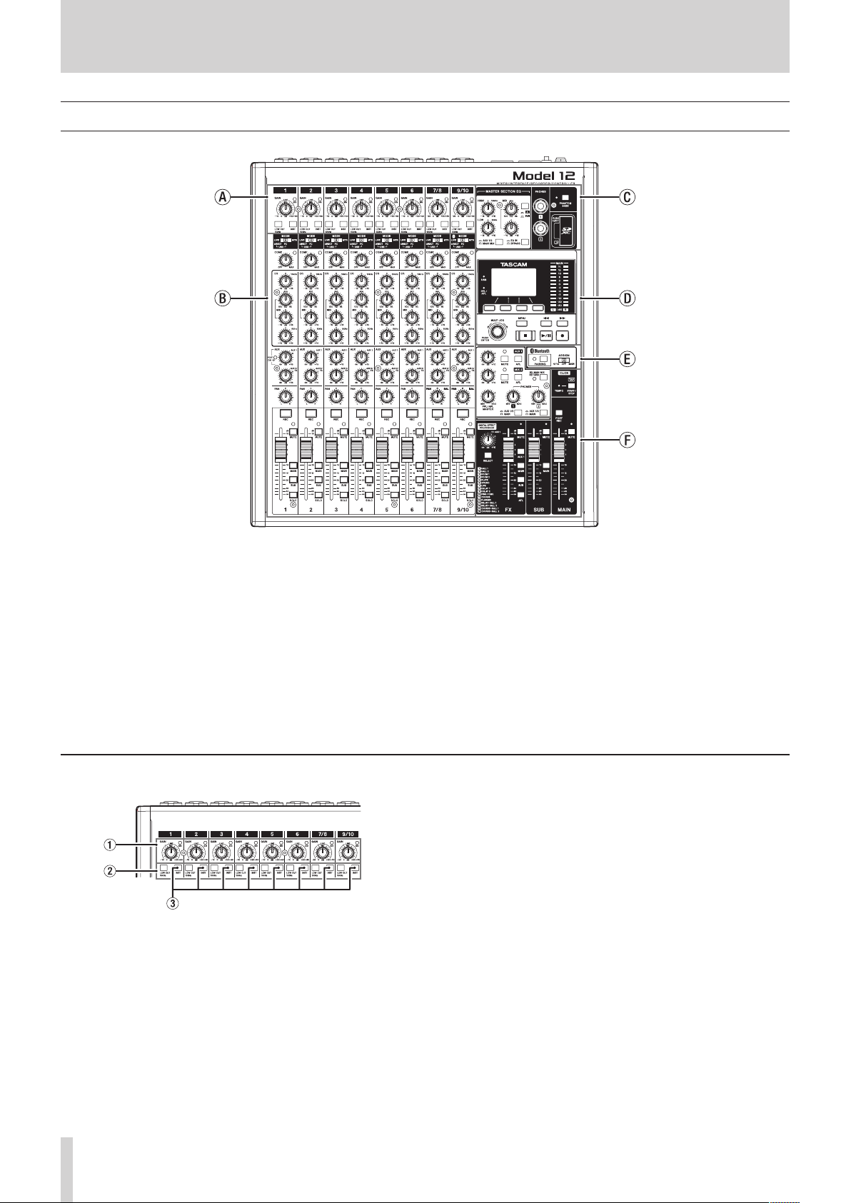
Top panel
a Input channel mixing section-1
Use this section to adjust the input levels of each channel.
b Input channel mixing section-2
Use this section to choose input sources for each channel,
adjust compressors and equalizers, and set levels sent to
each bus (MAIN MIX L/R, SOLO L/R, AUX1, AUX2/FX, SUB L/R).
(see “Input channel mixing section-2” on page 21)
c Equalizer section
Use this section to connect headphones and adjust the output
equalizer. (see “Equalizer section” on page 22)
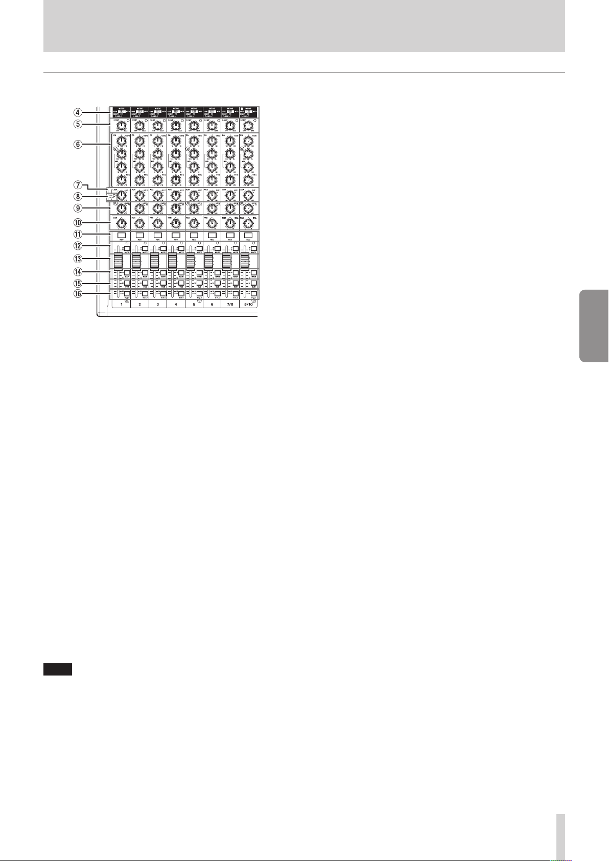
Input channel mixing section-1
1 GAIN knobs and SIG indicators (1-6, 7/8-9/10)
Use the GAIN knobs to adjust the input levels of each
channel.
its SIG indicator will light green when a signal is input
(-40dBu or higher: MIC input).
If a SIG indicator stays lit red continuously, lower the GAIN
knob (+7dBu or higher: MIC input).
d Screen operation section
Use this section to operate the meter, home and MENU
screens shown on the display. (see “Screen operation section”
on page 22)
e Monitoring section
Switch Bluetooth device input destinations, switch
monitoring destinations, and adjust AUX OUTPUT AUX 1/2
jack output levels. (see “Monitoring section” on page 23)
f Analog output adjustment section
Adjust the output levels of the built-in eects, and the
MAIN OUTPUT and SUB OUTPUT jacks. (see “Analog output
adjustment section” on page 24)
2 LOW CUT switches (1-6, 7/8-9/10)
Turn this switch on (pushed in) to enable low cut lters that
cut noise and other sounds at low frequencies.
3 INST switches (1-6, 7/8-9/10)
Set according to the MIC/LINE (BAL)/INST TRS input jack input
sources.
Turn the INST switch on (pushed in) when connecting an
guitar, bass or other equipment with high output impedance.
Turn the INST switch o (not pushed in) when connecting
electronic instruments, audio devices, mics and other
equipment.
20 TASCAM Model 12
Page 21
Input channel mixing section-2
4 MODE switches (1-6, 7/8-9/10)
Use these to select the input source for each channel. (see
“Setting the MODE switch” on page 39)
5 COMP knobs and indicators (1-6, 7/8-9/10)
Use these knobs to adjust the compression thresholds for the
signals input to each channel.
When compression is activated, the COMP indicators light.
6 EQ knobs (1-6, 7/8-9/10)
i Use these to boost and attenuate the HIGH, MID and LOW
bands of each channel.
Setting range: ±15 dB
i The central frequencies of the MID bands can be set.
Setting range: 100 Hz - 8 kHz (default: 600Hz)
7 AUX 1 knobs (1-6, 7/8-9/10)
Use these to adjust the levels of signals sent to the AUX 1 bus.
8 POST indicator (shared by all channels)
When this indicator is lit, signals are sent to the AUX 1 bus
after the channel faders. (see “Changing the positions that
signals are sent to the AUX 1 bus from each channel” on page
55)
9 AUX2/FX knobs (1-6, 7/8-9/10)
Use to adjust the levels of the signals sent to the AUX2/FX
bus (POST FADER).
0 PAN knobs (1-6, 7/8-9/10)
Use to adjust the stereo positions of the signals input to each
channel.
2 - Names and Functions of Parts
q REC buttons and indicators (1-6, 7/8-9/10)
Use these to select the channels to record to the SD card.
w MUTE switches and indicators (1-6, 7/8-9/10)
When these switches are on (pushed in, MUTE indicator lit),
those channels are muted.
e Channel faders (1-6, 7/8-9/10)
Use these to adjust the send levels of channel signals.
r MAIN switches (1-6, 7/8-9/10)
Turn these switches on (pushed in) to send channel signals to
the MAIN MIX L/R bus.
t SUB switches (1-6, 7/8-9/10)
Turn these switches on (pushed in) to send channel signals to
the SUB L/R bus.
y SOLO switches (1-6, 7/8-9/10)
Turn these switches on (pushed in) to send channel signals to
the SOLO L/R bus.
When these switches are on, the sound of their channels can
be heard through the SOLO L/R bus with headphones.
When the SOLO MODE screen setting is INPLACE SOLO,
the signals of channels that are not on will be muted. (see
“Setting the solo function for all channels” on page 55)
ENGLISH
NOTE
i When PAN knobs are centered (C), signals are reduced by 3
dB and sent to both left and right MAIN MIX L/R buses.
i When a PAN knob is turned all the way to the left (L), that
channel signal is sent only to the left MAIN MIX L/R bus. It is
not sent to the right bus.
i When a PAN knob is turned all the way to the right (R), that
channel signal is sent only to the right MAIN MIX L/R bus. It is
not sent to the left bus.
TASCAM Model 12 21
Page 22
2 - Names and Functions of Parts
Equalizer section
u MASTER SECTION EQ knobs
This 3-band semi-parametric equalizer aects signals output
from the MAIN OUTPUT and AUX OUTPUT AUX 1/2 jacks.
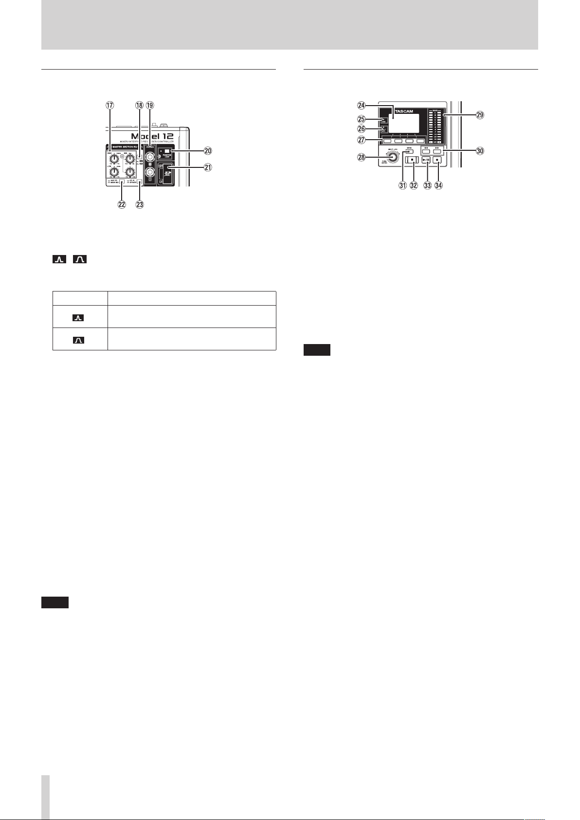
i / switch
This sets the acuteness of the MID band of the semiparametric equalizer.
Switch Meaning
On ( )
O ( )
o PHONES jack (1/2)
Use this standard stereo jack to connect stereo headphones.
Use an adapter to connect headphones with a mini plug.
Use these to monitor signals from the MAIN MIX L/R, AUX 1,
AUX 2/FX and SOLO L/R buses. (see “Block diagram / Schéma
fonctionnel / Diagrama de bloques” on page 209)
p PHANTOM +48V switch and indicator
Use this switch to supply +48V phantom power to the 1–6,
7/8 and 9/10 XLR jacks on the back of the unit.
The indicator lights when the PHANTOM +48V switch is set to
on (pushed in). (see “Setting phantom power” on page 39)
a SD card slot
Insert SD cards in this slot. (see “Inserting and removing SD
cards” on page 32)
s AUX 1/2/MAIN MIX switch
Set which output signals are aected by the equalizer.
AUX 1/2: Equalizer is applied to signals sent from the AUX
MAIN MIX: Equalizer is applied to signals sent from the
NOTE
Also set the EQ IN/BYPASS switch to “EQ IN”.
d EQ IN/BYPASS switch
When this switch is EQ IN, the equalizer will aect the output
signals set with the AUX 1/2/MAIN MIX switch.
When set to BYPASS, the equalizer will not be applied
regardless of the AUX 1/2/MAIN MIX switch setting.
The band is acute, making it aect a
narrower frequency band.
The band is less acute, making it aect a
broader frequency band.
1 and AUX 2/FX buses.
MAIN MIX L/R bus.
Screen operation section
f Display
Shows a variety of information.
g USB indicator
This lights when the USB connection is working.
h PFL/AFL indicator
This indicator lights when at least one channel SOLO switch
is on or when the AFL switch for the AUX 1 or AUX 2 knob or
the FX fader is on.
j Function buttons
The functions of these buttons change depending on the
screen shown on the display. The functions shown at the
bottom of the display are the currently assigned functions.
NOTE
For convenience, the four buttons under the display are
called the function buttons in this manual. From left to right,
they are called the F1, F2, F3 and F4 buttons.
k MULTI JOG dial
This dial functions as a dial when turned and as a button
when pressed.
Dial functions
i Turn when the Home Screen is open to move the le
playback position. (see “Locate function” on page 43)
i When a MENU Screen is open, turn to select items and
change setting values. (see “Basic MENU screen operations”
on page 29)
Button function
i Press when the Home Screen is open to designate a locate
point. (see “Locate function” on page 43)
i When a Menu Screen is open, press to conrm selections
and settings (ENTER button function).
l Output level indicators
These show the output levels of the MAIN OUTPUT jacks.
When the PFL/AFL indicator is lit, these show the output
levels from the SOLO L/R bus.
22 TASCAM Model 12
Page 23
2 - Names and Functions of Parts
; m/, buttons
i When stopped and during playback, press and hold these
buttons to search backward/forward.
i When the Home Screen is open, press the m button
to locate to the beginning of the current song (00:00:00,
which is the zero point).
i When the Home Screen is open, press the , button to
locate to the end of the current song.
i If the current song has auto punch in or out points set, you
can also locate to those points.
i If the current song has marks set, these can also be used to
locate to them.
i While pressing the 8 button, press the m button to
locate to the point where recording last started.
i While pressing the 8 button, press the , button to
locate to the point where recording last stopped.
i When the SD PLAY Screen is in playback state, press to skip
a le. (see “Playing WAV les on SD cards (SD PLAY mode)”
on page 62)
z MENU button
i When the Meter Screen is open, press to open the Home
Screen.
i When the MENU Screen or a menu item settings screen is
open, press to return to the Home Screen.
i When the Home Screen is open, press to open the MENU
Screen. (see “Menu structure” on page 28) and (see “Basic
MENU screen operations” on page 29)
x 8 button/indicator
Press to stop playback or recording.
This button lights when stopped.
Press this button when paused to return to the beginning of
the song or le.
c 7/9 button/indicator
Press this button to start playback.
This button lights during playback and recording.
This button blinks when paused.
v 0 button/indicator
Press this button to start recording.
This button lights during recording.
Press this button during playback to start recording (Manual
punch in).
Monitoring section
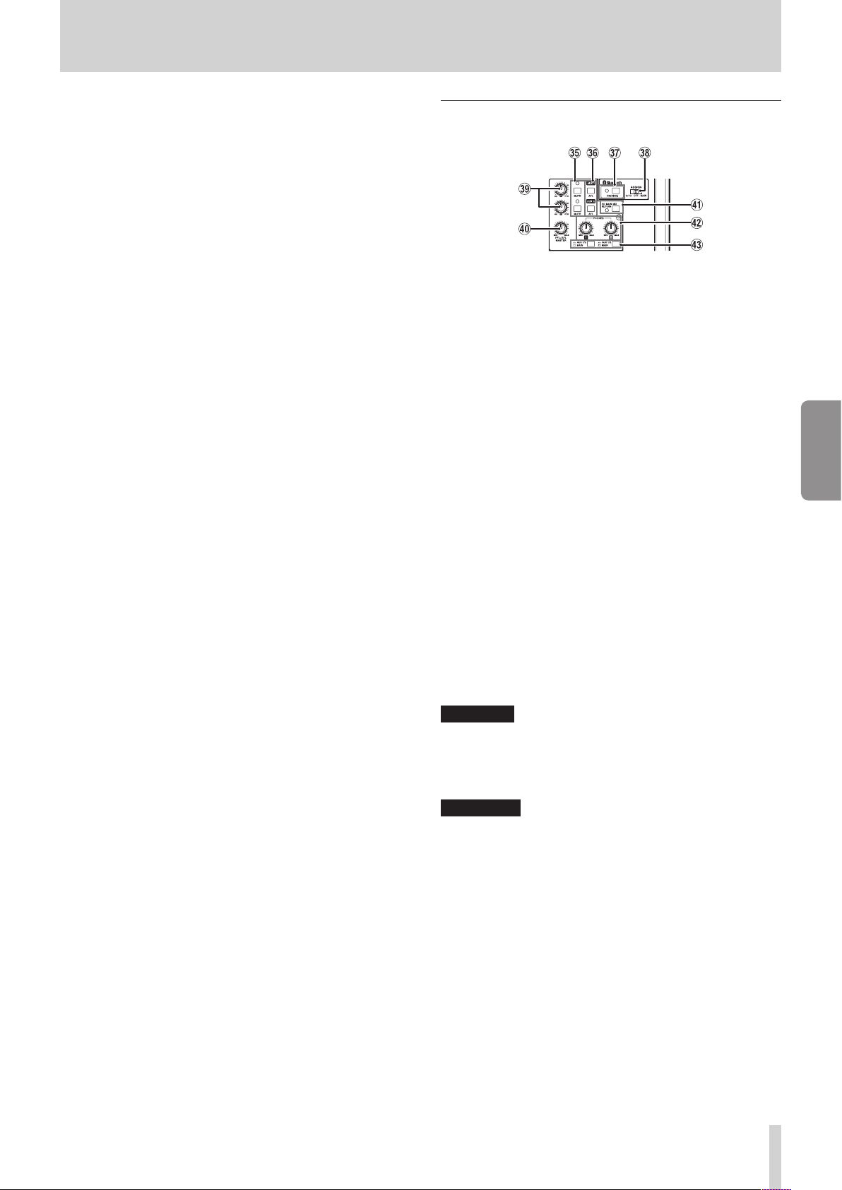
b MUTE switch/indicator (AUX 1/AUX 2)
When MUTE switches are on (MUTE indicators lit), signals to
the AUX OUTPUT AUX 1/2 jacks are muted.
n AFL switches (AUX 1/AUX 2)
When these switches are on (pushed in), the AUX OUTPUT
AUX 1/2 jack output signals are sent to the SOLO L/R bus.
When these switches are on, the sound of the SOLO L/R bus
can be heard through headphones.
m PAIRING button and indicator
Press and hold this button to activate Bluetooth pairing
mode.
Press when pairing to end pairing mode. (see “Connecting
with Bluetooth devices” on page 32)
, ASSIGN switch
Sound from the Bluetooth device is sent to channels 9/10
when this switch is set to “9/10” or the MAIN MIX L/R bus
when it is set to “MAIN”.
. AUX 1/AUX 2 knobs
Use to adjust the output levels of the AUX OUTPUT AUX 1/2
jacks.
/ PFL/AFL MASTER knob
Use this to adjust the send level from the SOLO L/R bus.
! SD MAIN MIX RETURN switch
When this switch is on (pushed in), playback of stereo master
les recorded on the SD card is output from the MAIN
OUTPUT jacks.
ATTENTION
Be aware that when this switch is on (pushed in), the sound
of the MAIN MIX L/R bus is not output.
@ PHONES knob (1/2)
Use this to adjust the headphone output level.
V
CAUTION
Before connecting headphones, minimize the volume with
the PHONES knob. Failure to do so could result in a sudden
loud noise that could harm hearing, for example.
# AUX 1/2 /MAIN switch
Turn these switches on to monitor signals from the AUX 1
and AUX 2/FX buses.
ENGLISH
TASCAM Model 12 23
Page 24
2 - Names and Functions of Parts
Analog output adjustment section
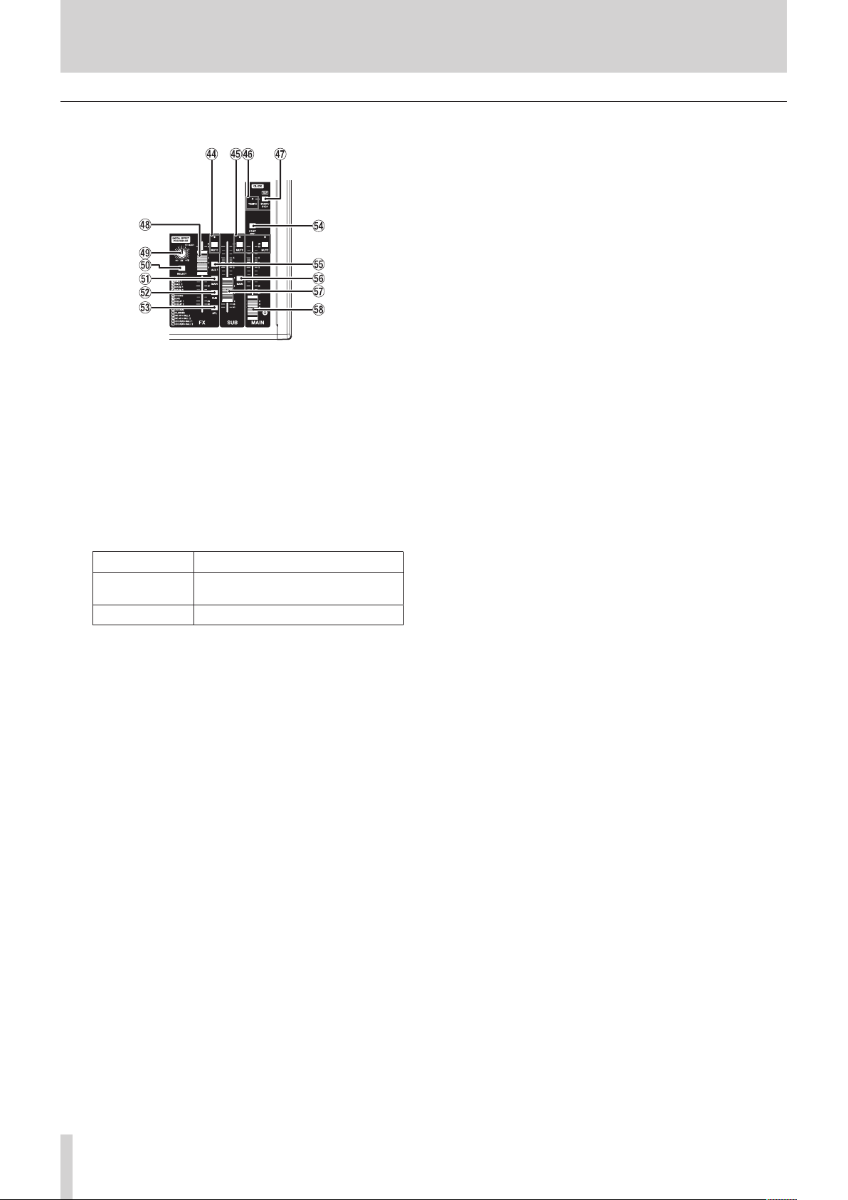
$ MUTE switch and indicator (FX)
When the MUTE switch are on (pushed in, MUTE indicator lit),
the signal from the built-in eect is muted.
% MUTE switches and indicators (SUB, MAIN)
When MUTE switches are on (MUTE indicators lit), signals to
the SUB OUTPUT/MAIN OUTPUT jacks are muted.
^ TEMPO indicator
i This lights green when a song that has click sound output
set is loaded.
i When the metronome is operating, it lights or blinks as
follows. (see “Metronome functions” on page 50)
Indicator color Meaning
Red
Green This blinks at the set tempo
& CLICK button
i When the EFFECT screen is open, tap this button
repeatedly at the desired speed to set the delay of the
built-in eect. (see “Setting the built-in eect” on page
41)
i When the TAP TEMPO screen is open, tap this button
repeatedly at the desired tempo to set the metronome.
(see “Making metronome settings” on page 51)
i Press this button when the metronome is stopped to start
it at the set tempo. Press this button when the metronome
is on to stop it. (see “Starting and stopping the metronome
manually” on page 52)
* FX fader
Use to adjust the levels of signals sent from the built-in eect
to the following buses.
i MAIN MIX L/R bus
i SOLO L/R bus
i AUX1 bus
i SUB L/R bus
( TO AUX 1 knob
Use these to adjust the levels of signals sent from the built-in
eects to the AUX1 bus.
This color lights on the rst beat of
the setting
) SELECT button
Open the EFFECT Screen and make built-in eect settings.
(see “Using the built-in eects” on page 41)
The built-in eect return signal is sent to the following buses.
i MAIN MIX L/R bus
i SOLO L/R bus
i AUX1 bus
i SUB L/R bus
Q MAIN switch (FX)
When this switch is on, signals from the built-in eect are
sent to the MAIN MIX L/R bus.
W SUB switch (FX)
When this switch is on, signals from the built-in eect are
sent to the SUB L/R bus.
E AFL switch (FX)
When this switch is on, signals from the built-in eect are
sent to the SOLO L/R bus.
When this switch is on, the sound of the SOLO L/R bus can be
heard with headphones.
R POST REC switch
Select the send position of the signal recorded to the SD
card.
When this switch is on, signals from after the MAIN fader are
recorded to the SD card.
T AUX 1 switch (FX)
When this switch is on, signals from the built-in eect are
sent to the AUX1 bus.
Y MAIN switch (SUB)
When this switch is on (pushed in), the SUB OUTPUT jack
output signal is sent to the MAIN MIX L/R bus.
U SUB fader
Use to adjust the output level of the SUB OUTPUT jacks.
I MAIN fader
Use to adjust the output level of the MAIN OUTPUT jacks.
24 TASCAM Model 12
Page 25
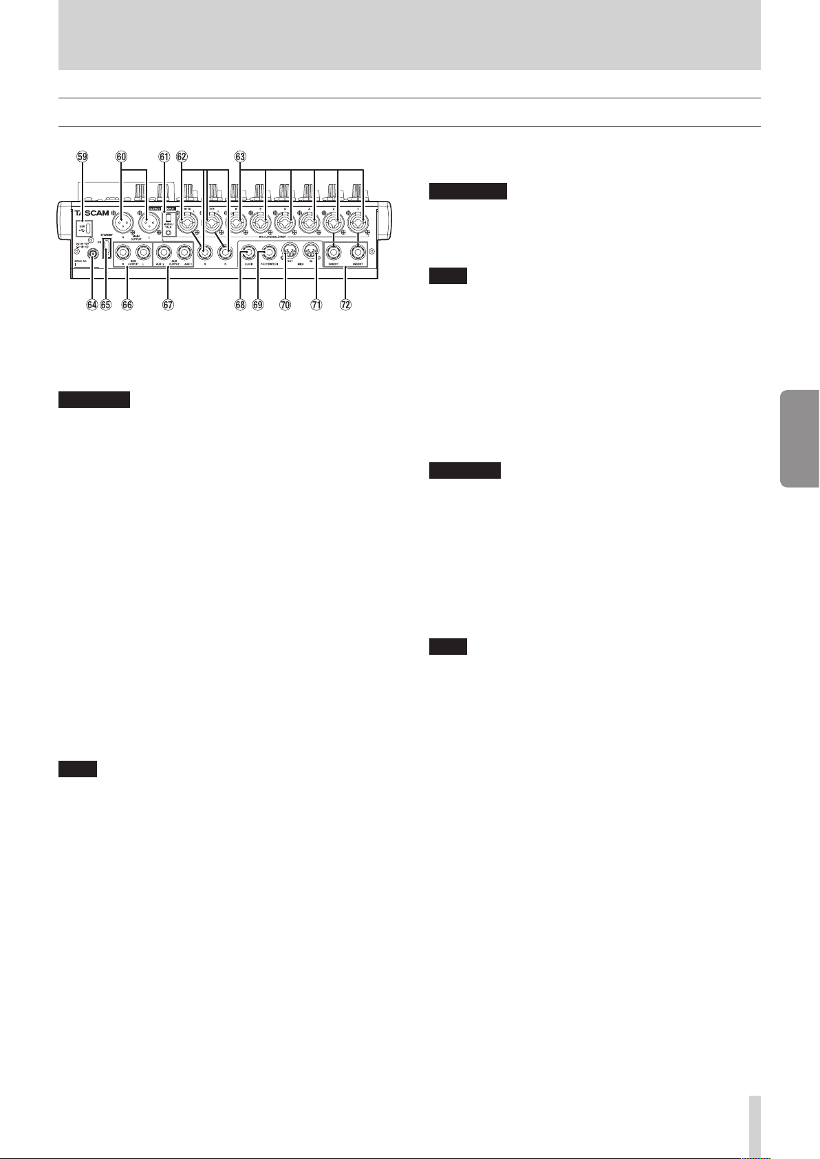
Rear panel
O USB port
This is a USB Type-C port. Use a USB cable (Type-A to Type-C)
to connect the unit to a computer. (see “Connecting with a
Computer” on page 63)
ATTENTION
The unit should be connected directly to the computer, not
through a USB hub. Moreover, noise could be picked up if the
cable is too long.
P MAIN OUTPUT L/R jacks
These analog outputs are XLR jacks.
i XLR (1: GND, 2: HOT, 3: COLD)
A MUSIC/TALK jack (9/10, 4-pole mini jack)
This is a 4-pole mini input/output jack.
By using a cable with a 4-pole mini plug, the signals output
from the MAIN OUTPUT jacks can be sent to the smartphone
while simultaneously receiving input from the smartphone.
S MIC/LINE (BAL)/INST input jacks (7/8-9/10)
These analog inputs are XLR/TRS combo jacks.
i XLR (1: GND, 2: HOT, 3: COLD)
i TRS (Tip: HOT, Ring: COLD, Sleeve: GND)
The balanced XLR jacks are for XLR balanced mic input.
The TRS jacks are for standard TRS stereo line input. If only
the L jack in a pair is connected, the same signal was be sent
to both left and right channels.
When directly connecting a guitar, bass or other instrument,
set the INST switch to on (pushed in).
NOTE
Activating the INST switch only aects the L jack.
D MIC/LINE (BAL)/INST input jacks (1-6)
These analog inputs are XLR/TRS combo jacks.
i XLR (1: GND, 2: HOT, 3: COLD)
i TRS (Tip: HOT, Ring: COLD, Sleeve: GND)
The balanced XLR jacks are for XLR balanced mic input.
The TRS jacks are for standard TRS mono line input.
When directly connecting a guitar, bass or other instrument,
set the INST switch to on (pushed in).
F DC IN 15V connector
Connect the included AC adapter (PS-M1524A) here. (see
“Connecting the power” on page 31)
2 - Names and Functions of Parts
G STANDBY switch
Press to turn the unit on and o.
V
CAUTION
Before turning the unit on, lower the volumes of connected
equipment to their minimum levels.
Failure to do so might cause sudden loud noises, which could
harm your hearing or result in other trouble.
NOTE
Do not do this when the unit is operating (including
recording, playing back or writing data to an SD card). Doing
so could cause proper recording to fail and recorded data to
be lost.
H SUB OUTPUT L/R jacks
These standard TRS jacks are analog outputs.
i TRS (Tip: HOT, Ring: COLD, Sleeve: GND)
J AUX OUTPUT AUX 1/2 jacks
These standard TRS jacks are analog outputs.
i TRS (Tip: HOT, Ring: COLD, Sleeve: GND)
ATTENTION
When the AUX OUTPUT AUX 2 jack is in use, the built-in
eects cannot be used. (see “Using the built-in eects” on
page 41)
K CLICK jack
This outputs the metronome click sound. (see “Setting the
click sound” on page 50)
L FOOTSWITCH jack
This standard TRS jack is for connecting a footswitch.
i TRS (Tip: FOOTSW1, Ring: FOOTSW2, Sleeve: GND)
NOTE
i This unit was designed to be used with unlatched
(momentary) footswitches that have to be pushed to
function (shorted when pushed). (see “Setting the footswitch
polarity” on page 57)
i By using a commercially-available splitter cable, two
footswitches can be used.
: MIDI OUT connector
This 5-pin DIN is a standard MIDI output connector.
This outputs MIDI signals sent from the computer.
If the MIDI TIMECODE or MIDI CLOCK/SPP items are set to
ON on the MIDI screen, those will also be output. (see “MIDI
functions” on page 53)
Z MIDI IN connector
This 5-pin DIN is a standard MIDI input connector.
MIDI signals input through this connector will be sent to the
computer.
X INSERT jacks (1-2, standard)
Use these standard TRS jacks to connect external devices
(eects).
i TRS (Tip: SEND, Ring: RETURN, Sleeve: GND)
ENGLISH
TASCAM Model 12 25
Page 26
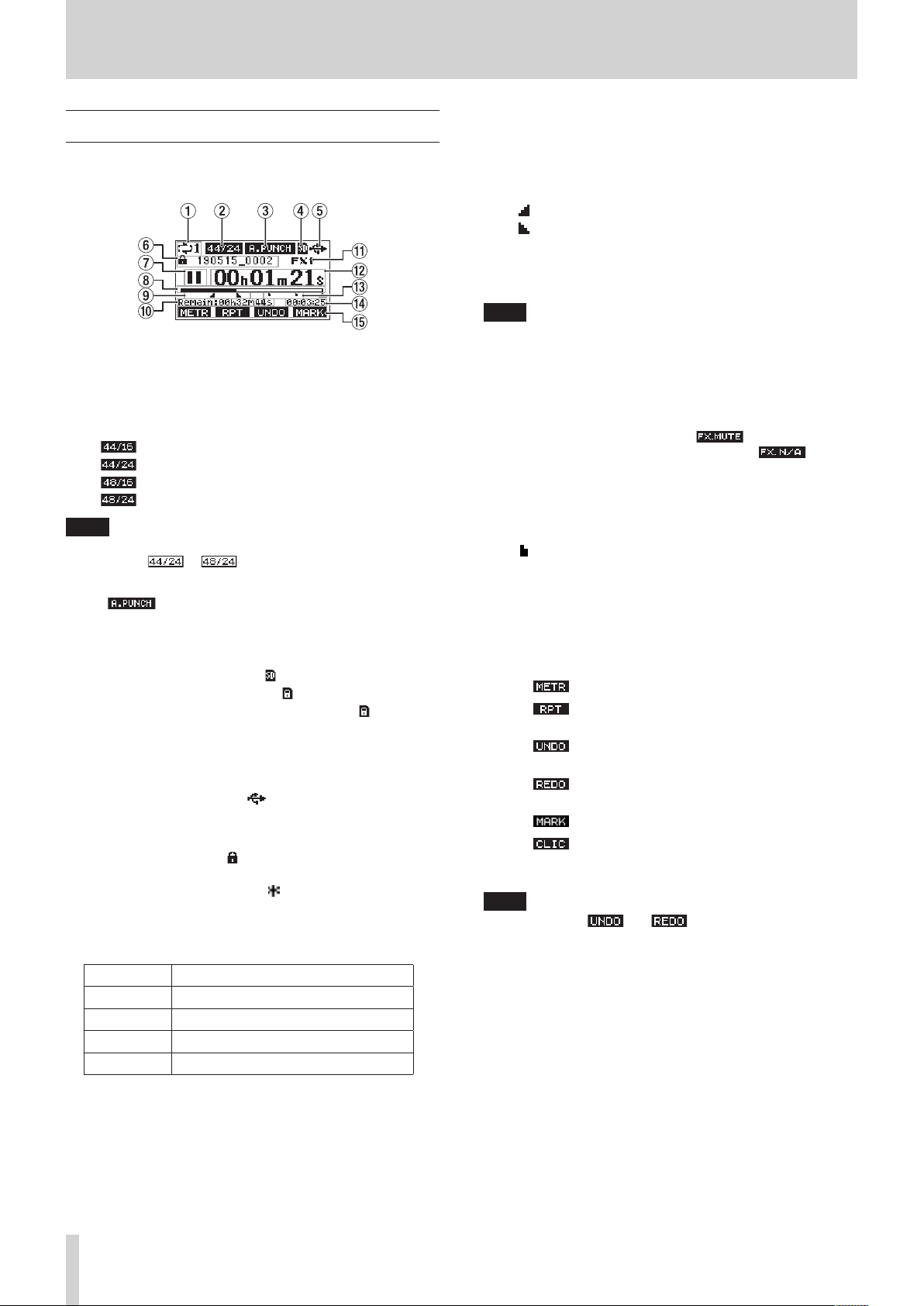
2 - Names and Functions of Parts
Home Screen
When the Meter Screen is open, press the MENU button to open
the Home Screen.
1 Repeat playback status
An icon appears when the repeat playback function is on.
(see “Repeat playback function” on page 43)
2 Song format
This shows the current song le format.
44.1kHz, 16bit
44.1kHz, 24bit
48kHz, 16bit
48kHz, 24bit
NOTE
If no song is loaded, the operation format of the unit will be
shown like or .
3 Automatic punch in/out function on/o status
The icon appears when the automatic punch in/
out function is on. (see “Automatic punch in/out function” on
page 44)
4 SD card present status
When an SD card is loaded, the icon appears.
When an SD card is protected, the icon appears.
Since system les cannot be updated when the icon
appears, automatic punch in/out settings will not be retained
and previously loaded songs will not be loaded when the
unit is turned on again.
5 USB connection status
During USB connection, the icon appears.
6 Song name
This shows the name of the current song.
If a song is protected, an icon appears before the le name.
(see “Protecting/unprotecting songs” on page 37)
If a song has unsaved marks, an icon appears before the
le name. (see “Adding marks” on page 49)
7 Transport status
This icon shows the recorder operation status.
Indicator Meaning
8
9
0
7
Stopped at the beginning of the le
Paused
Recording
Playback
8 Playback position
The current playback position is shown by a bar.
9 Automatic punch in/out point setting status
When the automatic punch in/out function is on, these show
the status of automatic punch in/out point setting.
Punch in point
Punch out point
0 Remaining time
The remaining time available for recording on the SD card is
shown (in hours: minutes: seconds).
NOTE
The remaining time that can be recorded on an SD card
varies according to the number of recording channels, song
format and SD card capacity.
q Built-in eect status
When a built-in eect is on, the number of the eect in use is
shown.
When the built-in eect is o, the icon appears.
When the built-in eect cannot be used, the icon
appears. (see “Using the built-in eects” on page 41)
w Recorder time counter
This shows the elapsed time from the beginning of the song.
e Mark indicators
An icon is shown at each mark.
r Song length
This shows the length of the current song (in hours: minutes:
seconds).
t Function button functions
This shows the functions assigned to the function button on
the Home Screen.
i F1 button: This opens the Meter Screen.
i F2 button: This turns the repeat playback function
on/o.
i F3 button: This returns to the state before the
previous operation.
i F3 button: This restores the state after the previous
operation.
i F4 button: This adds/deletes marks.
i F4 button: Open the METRONOME screen where
metronome functions can be set. (see
“Function button setting” on page 52)
NOTE
i The F3 button and indicators appear when
those operations are possible.
i Set the F4 button function on the KEY FUNCTION screen.
(see “Using mark functions” on page 49) and (see “Function
button setting” on page 52)
26 TASCAM Model 12
Page 27
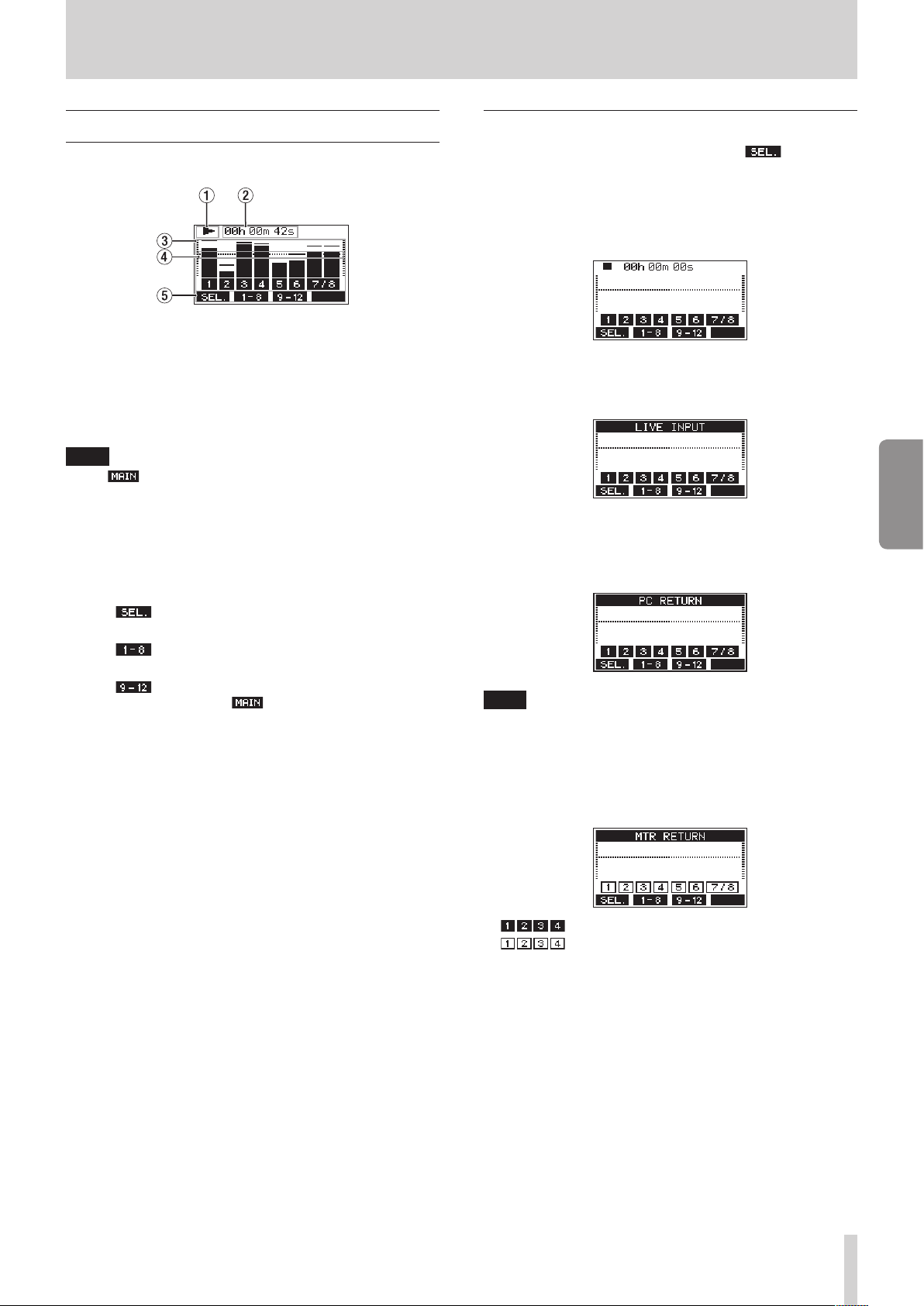
2 - Names and Functions of Parts
Meters Screen
This shows the levels of the signals being input to the unit.
1 Transport status
This icon shows the recorder operation status.
2 Recorder time counter
This shows the elapsed time from the beginning of the song.
3 Track level meters
These show the signal levels of each channel.
NOTE
The channels show the MAIN MIX L/R bus levels.
4 Level meter guide
This provides guidance for level adjustment. The guide is
shown at the -12dB level.
5 Function button functions
This shows the functions assigned to the function button on
the Meter Screen.
i F1 Press to change the input sources shown on
the Meter Screen.
i F2 Press to show the level meters for channel
1-8 signals on the Meter Screen.
i F3 Press to show the level meters for channel
9/10 and signals on the Meter Screen.
Meter Screen details
When the Meter Screen is open, press the F1 button to
change the signal sources shown by the meters.
Channel input level screens
The levels of signals input on each channel are shown
depending on their MODE switch settings.
LIVE INPUT Screen
This shows the levels of signals being input to the input jacks.
ENGLISH
PC RETURN Screen
This shows the levels of signals output from a computer when
used as a USB audio interface.
NOTE
Output from the computer, including from Windows Media
Player and iTunes, is sent to channels 1-2.
MTR RETURN Screen
This shows the playback signal levels of songs recorded on SD
cards.
Channels that have recording data in the song
Channels that do not have recording data in the
song
TASCAM Model 12 27
Page 28
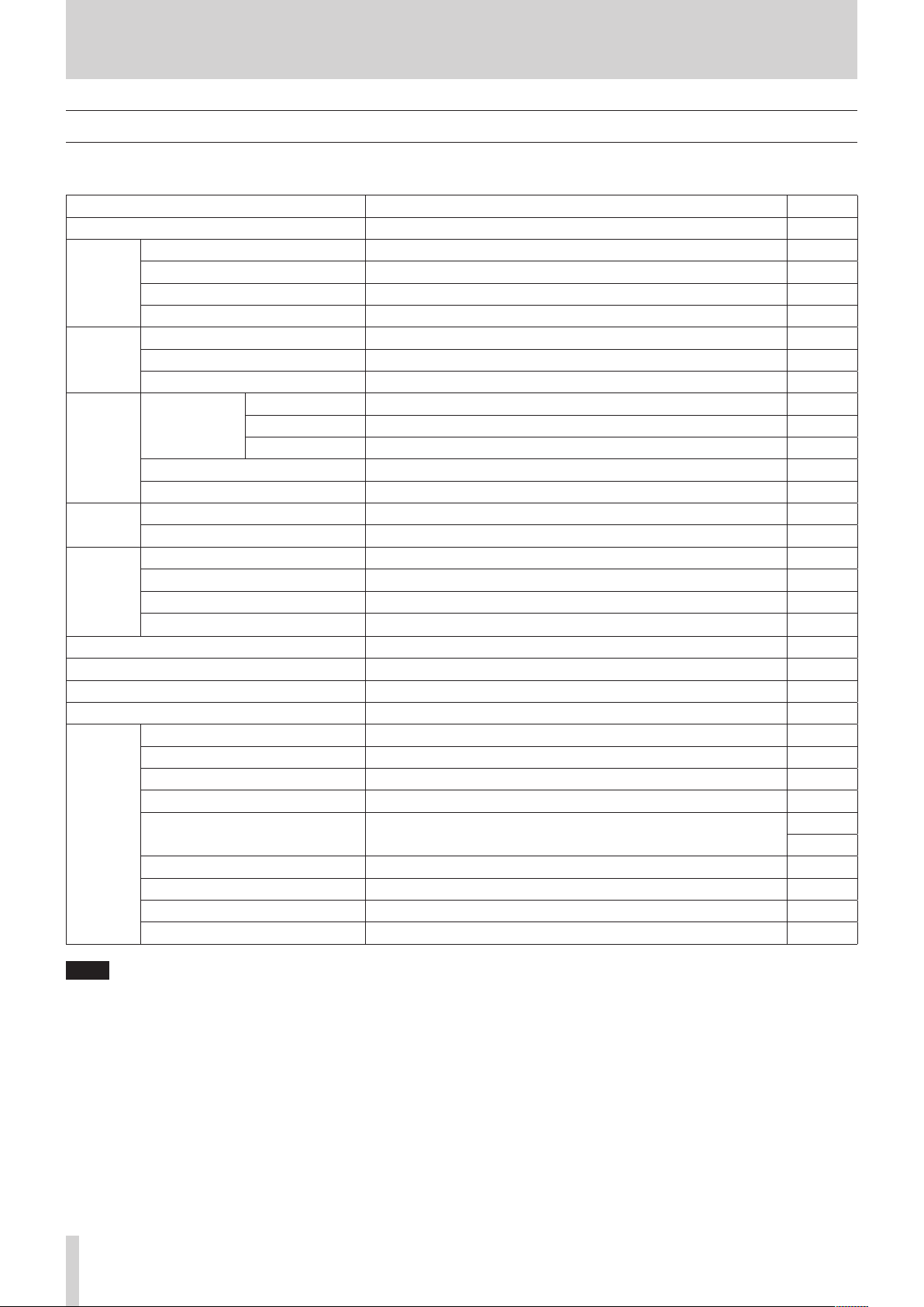
2 - Names and Functions of Parts
Menu structure
When the Home Screen is open, press the MENU button to open the MENU Screen.
The various menu items are as follows.
Menu item Function Page
SONG SONG Work with songs on an SD card page 36
VAMP OFF Disable VAMP playback function page 59
VAMP
CLICK
MTR
MIDI
MIXER
STEREO MIX EXPORT Use stereo mix export function page 48
SD PLAY Play WAV les on an SD card page 62
STORAGE SD cards can be accessed from a computer page 63
DAW CONTROLLER Set the DAW control mode page 57
SYSTEM
I/O EDIT Set VAMP in/out points page 57
I/O ALL CLR Clear all VAMP points page 58
VAMP PLAY Start VAMP playback function page 58
SETTING Set click sound operation and output destination page 50
METRONOME Make specic metronome settings page 51
COUNT IN Set the count in function page 52
TRACK CLEAR Clear specic tracks or all tracks page 46
TRACK EDIT
AUTO PUNCH Set the auto punch in/out function page 44
A.PUNCH PRE ROLL Set the pre-roll point page 44
MIDI TIME CODE Set the MIDI time code page 53
MIDI CLOCK/SPP Set MIDI clock and song position pointer page 53
MTR/USB SEND POINT Set when input signals are sent page 54
PHASE Set the phase of each channel page 55
AUX1 SEND Set the signal sent to the AUX 1 bus page 55
SOLO MODE Set the solo operation page 55
INFORMATION View SD card information, song information and the rmware version page 60
DATE/TIME Date and time settings page 33
SONG NAME Set the song name format page 60
DISPLAY Adjust the display page 34
KEY FUNCTION Set the function of the function button
FOOTSW Make footswitch settings page 56
USB AUDIO Make USB audio settings page 69
INITIALIZE Restore factory default settings page 61
MEDIA FORMAT Format the SD card page 61
IMPORT Import chosen WAV les to song tracks page 46
TRACK SWAP Swap song recording les page 47
page 49
page 52
NOTE
The settings for all menu items are retained even when the unit is turned o.
28 TASCAM Model 12
Page 29
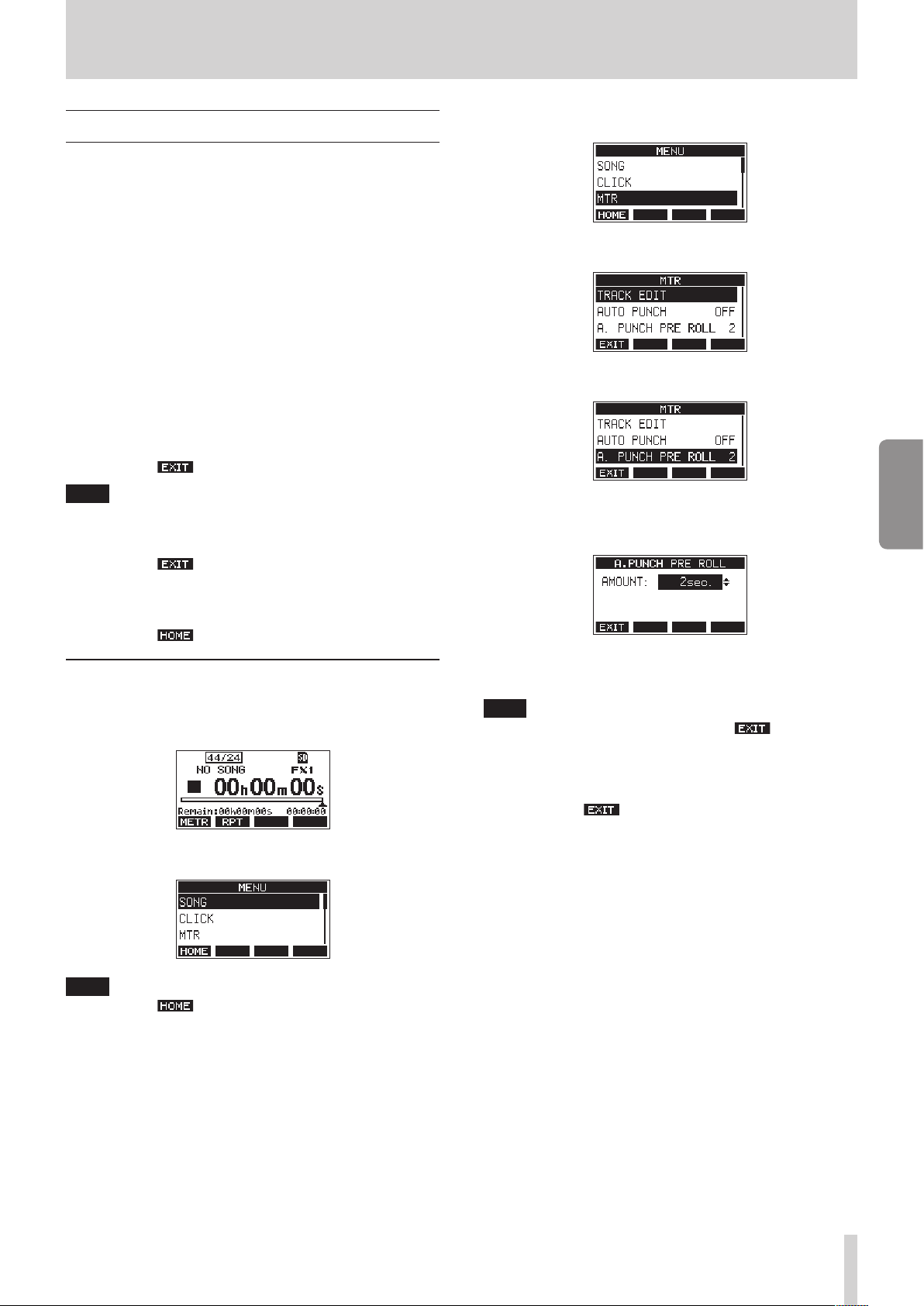
2 - Names and Functions of Parts
Basic MENU screen operations
After using the MENU button to open the MENU Screen, it can
be operated in the following manner.
This is an overview of basic operations. Function button
assignments dier according to the screen shown on the
display.
Selecting items (moving vertically on a page):
Turn the MULTI JOG dial.
Opening a submenu from a page:
Press the MULTI JOG dial.
Conrming a selected item:
Press the MULTI JOG dial (ENTER button function).
Returning to the previous screen without
conrming the selected item:
Press the F1 button.
NOTE
Some menu items are conrmed as soon as they are selected.
Going back one step in a menu:
Press the F1 button.
3. Turn the MULTI JOG dial to select dierent menu items.
4. Press the MULTI JOG dial to open a settings screen.
5. Turn the MULTI JOG dial to select the menu item to set.
A.PUNCH PRE ROLL selected
6. Press the MULTI JOG dial to open the settings screen.
ENGLISH
Returning to the Home Screen from a MENU
Screen:
Press the F1 button.
Menu operation procedures
This explanation uses an example of setting the pre-roll point.
1. Press the MENU button to open the Home Screen.
2. Press the MENU button to open the MENU Screen.
NOTE
Press the F1 button to return to the Home Screen.
A.PUNCH PRE ROLL Screen open
7. Turn the MULTI JOG dial to change the setting.
NOTE
To cancel a setting change, press the F1 button.
8. To set another item on the same screen, press the MULTI
JOG dial to move the cursor to the next setting.
9. Repeat steps 3 to 8 as necessary to set other items.
10. Press the F1 button to return to the MENU Screen.
TASCAM Model 12 29
Page 30

3 - Preparation
Connecting the power supply and other equipment
This is an example of Model 12 connections.
Precautions before making connections
o Carefully read the operation manuals of the devices to be connected and then connect them correctly.
o Before making connections, turn this unit and all equipment to be connected o (standby).
o Install all connected devices, including this unit, so that they are powered from the same line. When using a power strip or similar
device, be sure to use one that has high current capacity (thick cable) in order to minimize uctuations in power voltage.
o Before connecting audio equipment, set the following knobs and faders to their lowest values. Failure to do so could cause sudden
loud noises from monitoring equipment, and this could damage the equipment or harm hearing.
i GAIN knobs (channels 1-6, 7/8-9/10)
i Channel faders (channels 1-6, 7/8-9/10)
i SUB fader
i AUX 1/AUX 2 knobs
i MAIN fader
i PHONES knob
o Set the PHANTOM +48V switch to o.
30 TASCAM Model 12
Examples of connections to a Model 12
Page 31

3 - Preparation
Connecting the power
Use the included AC adapter (TASCAM PS-M1524A) to connect a
power supply to the unit as shown below.
Power outlet
DC plug
TASCAM PS-M1524A (included)
1. Connect the included AC adapter (TASCAM PS-M1524A) to
the DC IN 15V connector on the back of the unit.
2. Turn the nut on the DC plug to secure it to the DC IN 15V
connector.
ATTENTION
Always connect the included AC adapter (TASCAM PSM1524A) and AC adapter power cord. Use of a dierent
adapter could cause malfunction, re or electric shock.
Connecting microphones
Connecting smartphones/portable audio players
Use the MUSIC/TALK jack to connect a smartphone or portable
audio player.
By using a cable with a 4-pole (TRRS) mini plug to connect a
smartphone, the signals output from the MAIN OUTPUT jacks
can be sent to the smartphone while simultaneously receiving
audio signals from the smartphone on channels 9/10.
ATTENTION
i Connecting a cable to the MUSIC/TALK jack disables signals
input on channels 9/10 from the MIC/LINE jacks.
i Depending on the specications of the connected device,
normal input and output of sound signals might not be
possible.
NOTE
i When signals output from the MAIN OUTPUT jacks are
returned to the smartphone, echo will not occur on the
smartphone because the sound from the smartphone itself is
not included in those output signals.
i When using a stereo mini plug cable, only audio signal input
is possible.
ENGLISH
Connecting monitor speakers
Connect monitor speakers (powered speakers or an amplier
and speaker system) to the MAIN OUTPUT jacks.
Use the MAIN fader to adjust the speaker volume.
Dynamic mics
Connect them to the MIC/LINE (BAL)/INST input jacks on the
back of the unit.
Condenser mics
When using a condenser microphone that requires phantom
power, connect it to a MIC/LINE (BAL)/INST input jack and
then turn the PHANTOM +48V switch on (pushed in). (see
“Setting phantom power” on page 39)
The PHANTOM +48V indicator lights when the PHANTOM
+48V switch is on (pushed in).
Connecting guitars, basses and similar instruments
When connecting a guitar, bass or other instrument with high
impedance output (Hi-Z) directly to this unit, use the MIC/LINE
(BAL)/INST TRS input jacks, and turn the INST switch on (pushed
in) for that jack.
NOTE
When connecting an instrument with active output or when
the sound passes through an eects unit, for example, that is
connected to this unit, the INST switch does not need to be
set to on.
Connecting electronic devices and other audio equipment
Use the following inputs to connect electronic devices and other
audio equipment.
i MIC/LINE (BAL)/INST input jacks (1-6, 7/8-9/10)
Connecting headphones
Connect headphones to the PHONES jack (standard stereo).
The following signals can be monitored according to the SOLO
and AFL switch settings.
i Signals output from the MAIN OUTPUT connectors
i Signals output from the SOLO L/R bus
i Signals output from the AUX 1 bus
i Signals output from the AUX 2/FX bus
V
CAUTION
Before connecting headphones, minimize the volume with
the PHONES knob. Failure to do so could result in a sudden
loud noise that could harm hearing, for example.
Connecting a computer
Use the included Type-A-Type-C USB cable to connect the unit
to a computer USB 2.0 port.
When the USB connection is working, the USB indicator in the
screen operation section lights.
ATTENTION
The unit should be connected directly with the computer
instead of via a USB hub. Moreover, noise could be picked up
if the cable is too long.
Connecting with iOS devices
To connect this unit with an iOS device that has a Lightning
connector, use a Lightning to USB Camera Adapter* and a use
the included USB cable (Type-A to Type-C).
NOTE
When an INST switch is on (pushed in), input through the
MIC/LINE (BAL)/INST TRS input jacks will be unbalanced.
* You must obtain a genuine Apple Lightning to USB Camera
Adapter separately.
TASCAM Model 12 31
Page 32

3 - Preparation
Connecting with Bluetooth devices
This unit can input sound from a computer, portable audio
device or other equipment that supports Bluetooth (A2DP).
Pairing
Follow the procedures below to enable communication with a
Bluetooth device.
NOTE
Pairing also requires operation of the Bluetooth device.
Refer to the operation manual of the Bluetooth device for
procedures.
1. Set the ASSIGN switch to “9/10” or “MAIN”.
2. Conrm that the PAIRING indicator on this unit is blinking.
If it is unlit, press the PAIRING button.
NOTE
When the unit is turned on, it automatically becomes ready
for pairing. If 2 minutes pass in pairing mode, it will end. Press
this button to reactivate pairing mode when it is disabled.
3. Select “Model 12” (this unit) on the other Bluetooth device.
When pairing succeeds, the PAIRING indicator will stop
blinking and remain lit, and connection with the other
device will be complete.
NOTE
i Some older Bluetooth devices require the input of a passkey.
Enter “0000” in such cases.
i Pairing will automatically end if connection is not conrmed
within two minutes.
i When this unit is turned on, it will automatically try to
connect with the Bluetooth device to which it was previously
connected. At this time, pairing will automatically end after
ve minutes if connection is not possible because that
Bluetooth device is not turned on or its Bluetooth function is
turned o.
Unpairing
The Bluetooth device that is currently connected can be
unpaired from the unit.
1. Press and hold the PAIRING button for at least two seconds.
2. This ends the pairing. The PAIRING indicator will start
blinking and the unit will be ready to pair.
Inserting and removing SD cards
Inserting SD cards
Insert an SD card into the SD card slot on the top of the unit to
enable playback and recording by this unit.
NOTE
SD cards can be inserted whether or not the unit is on or o.
1. Open the SD card slot cover.
2. The SD card should be inserted with its label facing left.
3. Close the SD card slot cover.
Removing SD cards
Turn the unit o or stop operation before removing an SD card.
V
CAUTION
Never remove an SD card when the unit is operating
(including recording, playing back, or writing data to the SD
card). Doing so could cause proper recording to fail, data to
be lost, and sudden loud noises from monitoring equipment,
which might damage the equipment, harm hearing or cause
other trouble.
1. Press the SD card in gently to make it to come up.
2. Pull the SD card out.
SD card write protection switches
SD cards have write-protection switches that prevent writing
new data to them.
If you slide the write-protection switch to the “LOCK” position,
writing will not be possible. Move the write-protection switch
to the unlocked position in order to record, erase and otherwise
edit data on the card.
32 TASCAM Model 12
Page 33

3 - Preparation
Turning the power on and o
V
CAUTION
i Turn down the volume of the sound system connected to the
unit before starting up or shutting down the unit.
i Do not wear connected headphones when turning the unit
on and o. Loud noises could damage the speakers or harm
your hearing.
Before turning the power on
1. Make the following settings on the top of the unit.
i Other knobs w all the way left
i Faders w all the way down
i Switches w o (not pushed in)
2. Minimize the output levels of audio sources and input levels
of ampliers connected to this unit.
Turning the power on
1. Use the STANDBY switch on the back of the unit to turn its
power on.
Startup screen
Turning the power o
Before turning the power o, minimize the levels of output
faders and knobs, and then follow the procedures above in
reverse.
Failure to follow the correct order could result in clicking noises,
for example, that might damage equipment.
V
CAUTION
Do not disconnect the power cord when the unit is operating
(including recording, playing back, or writing data to an SD
card). Doing so could cause proper recording to fail, recorded
data to be lost, and sudden loud noises from monitoring
equipment, which might damage the equipment, harm
hearing or cause other trouble.
NOTE
When the unit is started up for the rst time (or when the
built-in clock is reset after being left unused without power
for a long time), the DATE/TIME Screen appears before the
Startup Screen to allow the date and time of the built-in clock
to be set. (see “Setting the built-in clock date and time” on
page 33)
Setting the built-in clock date and time
Using its internal clock, this unit includes the date and time
when a le is recorded.
1. When the recorder is stopped, select DATE/TIME on the
SYSTEM Screen, and open the DATE/TIME Screen. (see
“Menu operation procedures” on page 29)
ENGLISH
Meter Screen
After the unit starts and the Startup Screen is shown, the
Meter Screen will open.
NOTE
i Press the MENU button to open the Home Screen.
i After the unit is turned on, the PAIRING indicator will blink for
a set amount of time.
2. Turn connected input audio source devices on.
3. Finally turn ampliers on.
2. Turn the MULTI JOG dial to change a value, and press the
MULTI JOG dial to conrm it and move the cursor to the
next item.
NOTE
Use the F2 and F3 buttons to move the cursor.
3. Change the year, month, day, hour and minute in order, and
complete the date and time setting.
4. Press the F4 button to conrm the setting and return
to the SYSTEM Screen.
NOTE
i When making a setting, you can press the F1 button
to cancel the changes and return to the SYSTEM Screen.
i When setting the time, the time display will be stopped.
i By setting the TYPE item to “DATE” on the SONG NAME
Screen, the date and time set here can be used for song
names. (see “Setting the song name format” on page 60)
TASCAM Model 12 33
Page 34

3 - Preparation
Adjusting the display
The display contrast and brightness can be adjusted.
Adjusting the display contrast
1. When the recorder is stopped, select DISPLAY on the
SYSTEM Screen, and open the DISPLAY Screen. (see “Menu
operation procedures” on page 29)
2. Adjust the display contrast.
Options: 10 – 40 (default: 28)
3. Press the MULTI JOG dial to conrm the setting.
4. Press the F1 button to return to the SYSTEM Screen.
Adjusting the display brightness
1. When the recorder is stopped, select DISPLAY on the
SYSTEM Screen, and open the DISPLAY Screen. (see “Menu
operation procedures” on page 29)
2. Press the MULTI JOG dial to move the cursor to the DIMMER
item.
Preparing an SD card for use
In order to make an SD card usable in this unit, whether for
recording or playback, this unit must be used to create a system
le on it rst.
ATTENTION
In order to record, this unit must be used to format it rst.
(see “Formatting SD cards” on page 61)
1. “No sys le. Make sys le. Are you sure?” appears in a pop up
when a new card or a card formatted by another device is
inserted into the unit.
2. Press the MULTI JOG dial to create a system le.
When system le creation is complete, the Home Screen
will reopen.
3. Adjust the display brightness.
Options: HIGH (default), LOW
4. Press the MULTI JOG dial to conrm the setting.
5. Press the F1 button to return to the SYSTEM Screen.
34 TASCAM Model 12
Page 35

4 - Managing Songs
This recorder treats each recording data group as one song and
manages data by song.
For one song, WAV les are saved for 10 tracks and a stereo
master le.
These les are read-only format.
To record or produce music, a song that has already been
created needs to be loaded or a new song needs to be created.
This chapter describes functions that range from basic
operations such as procedures for loading songs and creating
new songs to various song management functions.
NOTE
i The maximum recording time for a single song is 23:59:59.
i To use the WAV les from a song in a DAW or other
application, copy them to a computer. Do not use the les on
the SD card directly.
Viewing the song list
To open a list of songs saved on an SD card, select SONG on the
MENU Screen, and press the MULTI JOG dial to open the SONG
Screen. (see “Menu operation procedures” on page 29)
DELETE
Deletes the selected song.
PROTECT
Protect the selected song.
UNPROTECT
Stop protection of the selected song.
RENAME
Edits the name of the selected song.
Creating a New Song
To record or play with this unit, you must create and load a song.
The following procedure can be used to create a new song.
1. Open the SONG Screen when the recorder is stopped. (see
“Menu operation procedures” on page 29)
2. Press the F4 button to open the NEW Screen.
ENGLISH
On the SONG Screen, the following functions are assigned to the
function buttons.
o Press the F1 button to return to the MENU Screen.
o Press the F2 button to show the date on the SONG
Screen.
o Press the F3 button to show the size on the SONG
Screen.
o Press the F4 button to open the NEW Screen where
you can create a new song. (see “Creating a New Song” on
page 35)
Song Operation
Select the desired song le on the SONG Screen and press the
MULTI JOG dial to open a pop-up menu list with possible song
operations.
To use a song operation, turn the MULTI JOG dial to select the
desired item, and press the MULTI JOG dial.
LOAD/SAVE
Loads the selected song.
When the selected song is the current song, SAVE will appear
and information about it will be saved.
3. Turn the MULTI JOG dial to select the recording le format.
Options: 44.1kHz - 16bit (default), 44.1kHz - 24bit, 48kHz -
16bit, 48kHz - 24bit
4. Edit the name of the song as necessary.
To edit the name of the song, press the F2 button to
open the NAME EDIT Screen.
For details about how to edit song names, see “Editing text”
on page 37.
TIP
The song name can also be edited later using the RENAME
Screen.
5. Press the F4 button to save the currently loaded
song and create a new song.
When song creation completes, the SONG Screen reopens.
NOTE
i To cancel song creation, press the F1 button.
i A maximum of 100 songs can be created on a single SD card.
i Songs are created in the “MTR” folder on the SD card.
i When new songs are created, the tempo is set to 120 and
the time signature is set to 4/4. (see “Making metronome
settings” on page 51)
INFORMATION
View information about the selected song.
CLR ALL MARKS
Clear all marks in the song.
TASCAM Model 12 35
Page 36

4 - Managing Songs
Loading Songs
Use the following procedure to load the song you want.
1. Open the SONG Screen when the recorder is stopped. (see
“Menu operation procedures” on page 29)
NOTE
The icon appears for a song currently being loaded. An
icon will appear before protected songs.
2. Select the song that you want to load and press the MULTI
JOG dial to open the menu list pop-up.
3. Select LOAD, and press the MULTI JOG dial.
After the selected song loads, the SONG Screen will reopen.
Saving the current song
Song information, including marks added during playback of
the current song as well as deleted marks, can be saved.
1. Open the SONG Screen when the recorder is stopped. (see
“Menu operation procedures” on page 29)
2. Select the current song, and press the MULTI JOG dial to
open the menu list pop-up.
3. Select SAVE, and press the MULTI JOG dial.
This saves the song information.
ATTENTION
After saving, undoing or redoing the previous operation will
no longer be possible.
Clearing all marks
This operation clears all marks added to the selected song.
1. Open the SONG Screen when the recorder is stopped. (see
“Menu operation procedures” on page 29)
2. Select the song with the marks that you want to delete and
press the MULTI JOG dial to open the menu list pop-up.
3. Select CLR ALL MARKS, and press the MULTI JOG dial.
The CLR ALL MARKS Screen will open.
4. Press the F4 button to conrm deletion of marks.
When mark deletion completes, the SONG Screen reopens.
ATTENTION
Deleted marks cannot be restored.
Deleting songs
You can delete songs.
Deleting unnecessary songs when the SD card space is low can
create more open space.
1. Open the SONG Screen when the recorder is stopped. (see
“Menu operation procedures” on page 29)
2. Select the song that you want to delete and press the MULTI
JOG dial to open the menu list pop-up.
3. Select DELETE, and press the MULTI JOG dial.
The DELETE Screen will open.
Viewing song information
You can check the song name (title), sampling frequency, bit
rate, size, and date and time last written.
1. Open the SONG Screen when the recorder is stopped. (see
“Menu operation procedures” on page 29)
2. Select the song with information that you want to check
and press the MULTI JOG dial to open the menu list popup.
3. Select INFORMATION, and press the MULTI JOG dial.
The INFORMATION Screen will open.
The song name, sampling frequency, bit rate, size, date and
time last written will be shown.
4. After checking, press the F1 button to return to the
SONG Screen.
4. Press the F4 button to conrm deletion.
When song deletion completes, the SONG Screen reopens.
ATTENTION
Deleted songs cannot be restored.
NOTE
i To cancel song deletion, press the F1 button.
i The current song cannot be deleted. To delete the current
song, load another song rst.
36 TASCAM Model 12
Page 37

4 - Managing Songs
Protecting/unprotecting songs
By protecting a song, you can disable editing, recording and
deletion operations for that song.
You can protect and stop protecting songs.
1. Open the SONG Screen when the recorder is stopped. (see
“Menu operation procedures” on page 29)
2. Select the song that you want to protect or unprotect and
press the MULTI JOG dial to open the menu list pop-up.
3. Select PROTECT or UNPROTECT, and press the MULTI JOG
dial.
The PROTECT or UNPROTECT screen will open.
4. Press the F4 button to protect or unprotect the song.
NOTE
To cancel protection or unprotection, press the F1
button.
5. When song protection or unprotection completes, the
SONG Screen reopens.
NOTE
i icons appear before songs that are protected in the song
list shown for copying, deletion and other operations.
i If you try to execute a prohibited operation (editing,
recording, deletion) on a protected song, “Song is protected.”
will appear in a pop-up message on the display.
Editing song names
1. Open the SONG Screen when the recorder is stopped. (see
“Menu operation procedures” on page 29)
2. Select the song with name that you want to change and
press the MULTI JOG dial to open the menu list pop-up.
3. Select RENAME, and press the MULTI JOG dial.
The RENAME Screen will open.
4. Edit the song name.
For details about how to edit song names, see “Editing text”
below.
NOTE
To cancel song name editing, press the F1 button.
5. When nished editing the song name, press the F4
button to conrm the song name.
When song name editing is complete, the SONG Screen
reopens.
Editing text
Use these operations to edit text.
Changing the cursor (editing point) position:
Use the F2 and F3 buttons.
You can also press the MULTI JOG dial to move to the next
character.
ENGLISH
Deleting the character at the cursor position:
Turn the MULTI JOG dial.
You can input up to 11 characters, including symbols,
numbers, and uppercase and lowercase letters.
Leaving a single space open:
Turn the MULTI JOG dial to select a blank space at the left end
of any row, and press the MULTI JOG dial.
Canceling edits:
Press the F1 button.
Conrming the changes:
Press the F4 button.
TASCAM Model 12 37
Page 38

4 - Managing Songs
Loading songs created on dierent
TASCAM Model series products
Songs created on TASCAM Model series products with dierent
channel counts can be loaded on this unit.
Use the following procedure to load the song you want.
1. Open the SONG Screen when the recorder is stopped. (see
“Menu operation procedures” on page 29)
2. Select the song that you want to load and press the MULTI
JOG dial to open the menu list pop-up.
The name of the product used to create the song will be
shown next to the LOAD item if it is dierent from this unit.
Loading a song made on a Model 24
Loading a song from a unit with more
channels on a unit with fewer channels
When loading a song from a unit with more channels on a
unit with fewer channels, some tracks will not be available for
recording and playback.
The unit will load tracks up to its number of channels from the
song in order from the rst.
MAIN MIX L/R tracks will be loaded as MAIN MIX L/R tracks.
The song will not be converted.
Example: Loading a song from a Model 24 to a Model 12
Source song Song after loading
Tracks 1–10 Tracks 1–10 are loaded.
Tracks 11–22 These are not loaded.
Track 23 (MAIN MIX L)
Track 24 (MAIN MIX R)
This is loaded as track 11 (MAIN
MIX L).
This is loaded as track 12 (MAIN
MIX R).
3. Select LOAD, and press the MULTI JOG dial.
After the selected song loads, the SONG Screen will reopen.
Loading a song from a unit with fewer
channels on a unit with more channels
When loading a song from a unit with fewer channels on a
unit with more channels, empty tracks will be created for the
additional channels and the song will be converted for use with
the model with more channels before loading.
Example: Loading a song from a Model 12 to a Model 24
Source song Song after loading
Tracks 1–10 Tracks 1–10 are loaded.
-
Track 11 (MAIN MIX L)
Track 12 (MAIN MIX R)
NOTE
i If the SD card is write-protected, the song will be loaded
without conversion. See “SD card write protection switches”
on page 32 for details about SD card write protection.
i If a song is protected, it will be loaded without conversion. It
will automatically be converted if protection is disabled. See
“Protecting/unprotecting songs” on page 37 for details
about song protection.
Empty tracks are created for tracks
11–22.
This is loaded as track 23 (MAIN
MIX L).
This is loaded as track 24 (MAIN
MIX R).
38 TASCAM Model 12
Page 39

5 - Basic recording
Selecting the input source
This unit has 10 input jacks (8 combo mic/line and 2 TRS line).
The MIC/LINE (BAL)/INST TRS input jacks support high
impedance input, including direct guitar input.
Turn the INST switch on (pushed in) when connecting an guitar
or similar instrument directly.
TIP
Set the INST switch to o, when connecting an electricacoustic guitar with a built-in preamp or an active electric
guitar, as well as when the signal passes through an eect
device between the guitar and this unit.
Setting the MODE switch
Using the MODE switch settings of each channel to select their
input sources individually.
LIVE: Use the signal from the input jack as the input source.
PC: Use a signal from a computer connected to the USB
port as the input source.
MTR: Use a playback signal from the SD card as an input
source.
When a MODE switch is set to “MTR”, the signal from the input
jack on that channel will be recorded.
This function is useful when recording and playing back
repeatedly because the monitored sound is automatically
switched according to the recording or playback status.
Sounds on channels when in MTR mode
Transport status REC button o REC button on
Stop Muted Sound from input jack
Playing back
Recording
Playback sound
only
Playback sound
only
Playback sound only +
sound from input jack
Sound from input jack
If you set the PHANTOM +48V switch to OFF while the
conrmation pop-up message is open, the message will close
and phantom power will not be enabled.
V
CAUTION
Set the following knobs and faders to their minimum values
before changing the PHANTOM +48V switch on/o setting.
Depending on the connected mics, sudden loud noises from
monitoring equipment could occur, and this could damage
the equipment or harm hearing.
• GAIN knobs
• Channel faders
• SUB fader
• AUX1/AUX2 knobs
• MAIN fader
• PHONES knob (1/2)
ATTENTION
i Before connecting condenser mics, turn this unit and all
equipment to be connected o (standby).
i The PHANTOM +48V switch turns it on/o for the input
channels (1-6,7/8-9/10) simultaneously. Do not turn the
PHANTOM +48V switch on (pushed in) when connecting a
mic that does not require phantom power.
i Do not connect or disconnect mics when the PHANTOM
+48V switch is on (pushed in). Doing so could cause a loud
noise and might damage this unit and connected equipment.
i Turn the PHANTOM +48V switch on (pushed in) only
whenusing a condenser microphone that requires phantom
power. Turning the PHANTOM +48V switch on (pushed in)
when a dynamic mic or other mic that does not require
it is connected could damage this unit and connected
equipment.
i When using condenser mics that require phantom power
and dynamic mics together, be sure to use balanced dynamic
mics. Unbalanced dynamic mics cannot be used when
phantom power is enabled.
i Supplying phantom power to some ribbon mics could break
them. If you are unsure, do not supply phantom power to a
ribbon mic.
Monitoring
ENGLISH
Setting phantom power
When connecting a condenser mic that requires phantom
power, press the PHANTOM +48V switch when the recorder is
stopped to turn phantom power on/o.
When phantom power is turned on, the PHANTOM +48V
indicator lights and a pop-up message appears on the display to
conrm turning it on.
Press the MULTI JOG dial to provide phantom power to the MIC/
LINE (BAL)/INST (1-6, 7/8 and 9/10) XLR connectors.
Monitoring is important when recording and mastering.
With this unit, monitoring is possible using an external
monitoring system (powered monitor speakers or an amp and
speakers) or using stereo headphones.
Use the SUB fader and PHONES knob to adjust the level of the
monitoring system.
TASCAM Model 12 39
Page 40

5 - Basic recording
SIG indicators and level meters
The channel 1-6, 7/8-9/10 SIG indicators and level meters shown
on the Meter Screen can be used to check the levels of this unit’s
audio signals.
The level meters are for visually checking signal levels and can
also be used to check whether or not signals are being input to
this unit.
For example, even if nothing can be heard when monitoring,
if the Meter Screen level meters are moving, signals are being
input to this unit.
The SIG indicators light green when signals (of at least -40 dB)
are input through their channels.
If a SIG indicator lights red, the input source signal is too loud or
the GAIN knob is turned up too far.
If the SIG indicator lights red even when the GAIN knob is turned
all the way to the left, the input source signal is to loud. Lower
its volume.
Track level meters (1-6, 7/8-9/10)
The show track playback signal or track input signal levels.
Channels for which the MODE switch is set to “MTR” will show
the following signal levels according to the operation status.
REC button Transport status Level meter display
Unlit PLAY Track playback signal
Playback signal Track
Blinking
(recording standby)
Blinking (recording) Record Track input signal
NOTE
When the playback signal is shown, the level of the recorded
signal on the track is being shown, so the levels of the level
meters cannot be changed.
When the input signal is shown, adjusting channel 1-6, 7/89/10 GAIN knobs will change the levels of the level meters.
TIP
Please see “Meter Screen details” on page 27 for details
about the Meter Screen.
PLAY
Stop Track input signal
MAIN MIX L/R level meters (MAIN)
These show the MAIN MIX L/R bus levels.
input + playback
signal
Recording
This unit can simultaneously record up to 12 tracks, including 10
channel inputs and the MAIN MIX L/R bus.
The following recording operations assume that mics, guitars
and other things to record have been connected to the unit,
input signals have been assigned as track recording sources,
monitoring equipment has been connected and a song has
been loaded.
1. Press the REC buttons for channel to record.
Press the REC button to start recording standby. It will blink
red.
When a MODE switch is set to “MTR”, the signal from the
input jack on that channel will be recorded. (see “Setting
the MODE switch” on page 39)
NOTE
i The MAIN MIX L/R bus does not have a REC button, but it is
always in recording standby. The signals of the MAIN MIX L/R
bus will always be recorded if the 0 button is pressed.
i When the REC buttons of tracks that already have recordings
is blinking, press them to make them unlit.
2. Set the recording levels.
Use the GAIN knobs of each channel to adjust their input
levels.
Watch the SIG indicators above and to the right of the GAIN
knobs, and set the levels suitably.
At the same time, check that the sound heard through
headphones or a monitoring system is not distorted and
that an unintended eect has not been set.
NOTE
If an input is too loud, the SIG indicator will light red.
If the SIG indicator lights red even when its GAIN knob is
turned all the way to the left, lower the volume of the input
source.
3. Press the 0 button.
Recording will start and the 0 and 7/9 buttons will
light.
The REC buttons for tracks to record will stop blinking and
stay lit.
4. When recording has completed, press the 8 button.
5. Use the m/, buttons and 8 button, for example to
locate to a position you want to check.
TIP
For details about the locate function, see “Locate function” on
page 43.
6. Press the 7/9 button to play the recorded tracks.
Use the channel and MAIN faders to adjust the playback
levels.
Use the volume of the monitoring system to adjust the nal
monitoring level.
Use the PAN knobs of each channel to set the position of
each track signal between left and right speakers.
40 TASCAM Model 12
NOTE
i The channel PAN knobs and channel faders control the
playback output signals of already recorded tracks or the
monitoring volume of input signals. They do not control
signals to be recorded.
i If you are not satised with a recording, repeat the above
procedure from the beginning.
Page 41

5 - Basic recording
Undoing operations
If you make a mistake operating the unit or want to do a
recording over, for example,the operation last conducted can be
undone. Editing, recording and other operations can be undone.
The following types of operations can be undone.
o Recording operations
o Auto punch in/out operations
o Track clearing operations
If a song is loaded or the unit is turned o, Information used
for undoing and redoing will be lost, so undoing and redoing
previous operations will no longer be possible.
NOTE
Files used for undoing are temporarily saved on the SD card.
If you want to delete those les to make more space on the
SD card, reload the current song on the SONG Screen.
Undoing the previous operation
1. When the Home Screen is open, press the F3 button.
Using the built-in eects
This unit has built in eects, so you can apply eects without an
external eect device.
Channels 1-6 and 7/8-9/10 can have an eect applied. Their
signals are sent to the built-in eect by the AUX2/FX bus.
The return signal is sent to the following buses.
i MAIN MIX L/R bus
i SOLO L/R bus
i AUX1 bus
i SUB L/R bus
ATTENTION
When the AUX OUTPUT AUX 2 jack is in use, appears
on the Home Screen and the built-in eects cannot be used.
1. Use the AUX 2/FX knobs of each channel to adjust the levels
of signals sent to the AUX2/FX bus.
2. Use the EFFECT Screen to select the type of eect. (see
“Setting the built-in eect” on page 41)
3. Use the FX fader and TO AUX 1 knob to adjust the return
levels for each bus.
Setting the built-in eect
ENGLISH
The following conrmation pop-up message will appear.
2. Press the F4 button to return to the state before the
previous operation.
NOTE
To cancel undoing, press the F1 button.
Redoing an undone operation
1. After undoing, when the “ ” appears on the Home
Screen, press the F3 button.
The following conrmation pop-up message will appear.
1. Press the SELECT button to open the EFFECT Screen.
2. Turn the MULTI JOG dial, and set the built in eect type.
Options: 1.HALL1 (default), 2.HALL2,
3.ROOM1, 4.ROOM2,
5.PLATE, 6.STUDIO,
7.LIVE, 8.DELAY1,
9.DELAY2, 10.PING PONG,
11.CHORUS, 12.FLANGER,
13.DELAY+HALL1, 14.DELAY+HALL2,
15.CHORUS+HALL1, 16.CHORUS+HALL2
3. Press the MULTI JOG dial to select the PARAMETER item.
The parameter item is dependent on the selected eect.
2. Press the F4 button to restore the previous operation
and return to the state before undoing.
NOTE
To cancel redoing, press the F1 button.
TASCAM Model 12 41
Page 42

5 - Basic recording
4. Turn the MULTI JOG, and adjust the set eect.
You can check the eect as you change it.
NOTE
i Turn the MULTI JOG dial to change the F4 button function
from to . Press the F4 button to return to
the state before turning the MULTI JOG dial.
i Press the F4 button to set a parameter value to its
default.
i “ ” appears for eects that include delay. When the TIME
parameter item is selected, the CLICK button can be pressed
repeatedly at the desired speed to set the tempo.
i When the footswitch setting is “TAP”, the footswitch can be
used instead of the CLICK button for TAP delay input. (see
“Setting up the footswitch” on page 56)
5. Press the F2 button to turn the built-in eect on/o.
The A item on the EFFECT screen shows the built-in eect
status.
Using the library
This unit has a library function that allows up to 10 built-in eect
settings to be saved.
Saving eects settings in the library
1. Press the SELECT button to open the EFFECT Screen.
2. Press the MULTI JOG dial to select the LIB item.
3. Turn the MULTI JOG dial to select the library number to
save.
4. Follow the procedures in “Setting the built-in eect” to set
the built-in eect.
This saves the eect setting in the library.
Using an eect setting saved in the library
1. Press the SELECT button to open the EFFECT Screen.
2. Press the MULTI JOG dial to select the LIB item.
3. Turn the MULTI JOG dial to select the library number with
the saved eect setting you want to use.
This applies the saved eect setting.
Status Meaning
ON (default) The built-in eect is on.
OFF The built-in eect is o.
N/A
NOTE
When the built-in eect is o, the icon appears on the
Home Screen.
The built-in eect cannot be used
(because the AUX 2 jack is in use).
6. Press the F1 button to return to the Home Screen.
42 TASCAM Model 12
Page 43

6 - Recorder functions
Locate function
When the Home Screen is open, you can use the MULTI JOG dial
to set the locate point.
On the Home Screen, the current position of the recorder is
shown as a time in hours (h), minutes (m) and seconds (s).
By setting the time in this display area, you can change the
current position of the recorder.
Changing the playback position
When the Home Screen is open and the recorder is stopped or
playing back, you can use the MULTI JOG dial to set the locate
point.
Using the direct locate function to locate
1. When the Home Screen is open and the recorder is
stopped, press the MULTI JOG dial to enable direct locate
mode. A cursor will appear at the location to be changed in
the recorder counter.
2. Press the REC button for the track with the part to be
replaced to enter recording standby (REC button blinks).
NOTE
i Set the punch in and out points at least one second apart.
i Punch in recording is not possible when the REC button is on
for eight or more channels.
3. Start playback before the part to be replaced.
4. When the part to be replaced is reached, press the 0
button, and perform the part.
Recording will start (punch in).
5. When the end of the part to be replaced is reached, press
the 8 button.
The unit will switch to playback and then stop after two
seconds.
Using the footswitch to punch in/out
By connecting the recommended TASCAM RC-1F footswitch
(sold separately) to the FOOTSWITCH jack on the top of the unit,
you can use it to punch in/out.
To use a footswitch to punch in/out, you must set the foot
switch function assignment to “PUNCH I/O” in advance. (see
“Setting up the footswitch” on page 56)
ENGLISH
2. Turn the MULTI JOG dial to change a value, and press the
MULTI JOG dial to conrm it and move the cursor to the
next item.
3. Change the seconds, minutes and hours in that order to
move to that time as the current recorder position.
4. Press the 7/9 button to start playback or the 0 button
to start recording from that position.
Repeat playback function
The repeat playback function can be used to play something
over and over.
When the Home Screen is open, press the F2 button to
set the repeat playback function.
Nothing shown: The current song will keep playing
regardless of whether the area is recorded
or not.
: The current song will play and then stop.
: The current song will play repeatedly.
Punch in/out function
Punching in and out is a technique used to replace parts of
already recorded tracks.
You can start playback of a recording, switch to recording when
it reaches the part to be replaced (punch in), and then switch
back to playback when the end of that part is reached (punch
out) and stop after two seconds.
1. Determine the part you want to replace in advance.
Select a point where the replacement audio can be
combined well with the original track audio.
At step 4 above, press the footswitch instead of the 0 button,
and at step 5 press it again instead of the 8 button.
TASCAM
RC-1F
NOTE
This unit was designed to be used with unlatched
(momentary) footswitches that have to be pushed to
function (shorted when pushed).
TASCAM Model 12 43
Page 44

6 - Recorder functions
Automatic punch in/out function
Using the automatic punch in/out function, you can
automatically record between punch in and out points set in
advance.
To use the automatic punch in/out functions, start playback
from a pre-roll point before the punch in point where recording
will start.
Recording will stop when the punch out point is reached, but
playback will continue for two seconds before stopping.
Setting the punch in/out points
1. When the recorder is stopped, select MTR on the MENU
Screen, and open the MTR Screen. (see “Menu operation
procedures” on page 29)
2. Select AUTO PUNCH on the MTR Screen, and open the
AUTO PUNCH Screen.
3. Press the 7/9 button to start playback.
4. Press the MULTI JOG dial to set the punch in and out points.
The set points are shown next to the IN and OUT items.
NOTE
i You can also turn the MULTI JOG dial to set the points.
i Set the punch in and out points at least one second apart.
i Press the F2 button to clear set punch in and out
points.
i Press the F3 button to select either the punch in or
out point. An icon will appear next to the selected item.
5. Press the 8 button to stop playback.
6. Press the F4 button to turn the automatic punch in/
out function on.
The icon appears on the AUTO PUNCH Screen.
Setting a pre roll point
When using automatic punch in, the amount of playback time
before the punch in point can be set (pre roll point).
1. When the recorder is stopped, select MTR on the MENU
Screen, and open the MTR Screen. (see “Menu operation
procedures” on page 29)
2. Select A.PUNCH PRE ROLL on the MTR screen to open the
A.PUNCH PRE ROLL screen.
3. Set the pre-roll point.
Option Meaning
Do not locate to a point before the
OFF
1sec. – 10sec.
(default: 2sec.)
punch in point. Manually moving to
somewhere before the punch in point
beforehand will be necessary.
Locate to a pre roll point the set time
before the punch in point and start
playback.
4. Press the F1 button to return to the MTR Screen.
Rehearsing punching in and out
You can rehearse before punch in/out recording. In rehearsal,
recording will not occur, but monitoring will be the same as if
recording.
1. Press the MENU button when the recorder is stopped to
open the Home Screen.
Conrm that the icon appears on the Home Screen.
7. Press the F1 button to return to the MENU Screen.
TIP
i By setting only the punch in point, you can start recording
with automatic punch in and then continue recording until
you press the 8 button to stop.
i By setting only the punch out point, you can start recording
by pressing the 0 button and then stop recording with
automatic punch out.
44 TASCAM Model 12
2. Press the REC buttons for the tracks you want to record
using automatic punch in/out.
NOTE
Punch in recording is not possible when the REC button is on
for eight or more channels.
3. Press the 7/9 button.
Auto punch in/out rehearsal starts.
i The transport starts playback from the pre-roll point.
Both track playback and input source signals can be
monitored. (see “Setting a pre roll point” on page 44)
i When the punch in point is reached, only the input
source signal will be monitored. The 0 button will
blink showing that it is rehearsal mode.
i When the punch out point is reached, both track
playback and input source signals will be monitored.
The 0 button will become unlit.
i Playback will automatically stop two seconds after the
punch out point. The 7/9 button will blink.
Rehearsal can be repeated.
Page 45

Using automatic punching in and out
Follow these procedures to punch in and out automatically and
record.
1. Conrm that the icon appears on the Home Screen.
2. Press the REC buttons for the tracks you want to record
using automatic punch in/out.
NOTE
Punch in recording is not possible when the REC button is on
for eight or more channels.
3. Press the 0 button.
i The transport starts playback from the pre-roll point.
Both track playback and input source signals can be
monitored. (see “Setting a pre roll point” on page 44)
i When the punch in point is reached, only the input
source signal will be monitored. The 0 button will
light.
i When the punch out point is reached, both track
playback and input source signals will be monitored.
The 0 button will become unlit.
i Playback will automatically stop two seconds after the
punch out point. The 7/9 button will blink.
6 - Recorder functions
ENGLISH
TASCAM Model 12 45
Page 46

7 - Track editing
Clearing tracks
The selected track will be cleared.
1. When the recorder is stopped, select MTR on the MENU
Screen, and open the MTR Screen. (see “Menu operation
procedures” on page 29)
2. Select TRACK EDIT on the MTR Screen, and open the TRACK
EDIT Screen.
3. Select TRACK CLEAR on the TRACK EDIT Screen, and open
the TRACK CLEAR Screen.
Importing tracks
You can import audio les that you have to tracks in the current
song.
Files that can be imported to tracks must be WAV (BWF) format
(“.WAV” extension).
To import an audio le with a dierent format (.mp3, etc.) to this
unit, it must be converted to a WAV le that matches the format
of the song it will be imported into beforehand.
1. Connect this unit with a computer. (see “Connecting with a
Computer” on page 63)
2. Use the computer to copy WAV les on it to this unit’s
“MUSIC” folder.
3. Follow the proper disconnection procedures on the
computer before disconnecting the USB cable. (see
“Disconnecting” on page 64)
4. When the recorder is stopped, select MTR on the MENU
Screen, and open the MTR Screen. (see “Menu operation
procedures” on page 29)
5. Select TRACK EDIT on the MTR Screen, and open the TRACK
EDIT Screen.
6. Select IMPORT on the TRACK EDIT Screen, and open the
TRACK IMPORT Screen.
WAV les in the “MUSIC” folder will be shown.
4. Turn the MULTI JOG dial to select the track to clear, and
press the MULTI JOG dial.
A conrmation message will appear.
NOTE
Press the F2 button to open a message asking to
conrm that you want to clear all tracks.
5. Press the F4 button to clear the track(s).
After clearing tracks completes, the TRACK CLEAR Screen
will reopen.
NOTE
i To cancel clearing tracks, press the F1 button.
i Undoing is possible only for the last cleared track.
7. Select a WAV le to import.
i Turn the MULTI JOG dial to select a WAV le.
i Press the MULTI JOG dial when a folder is selected to
show its contents.
i Press the F1 button to return to the MENU
Screen.
i Press the F2 button to move up one level.
8. Press the F4 button.
A conrmation message will appear if the bit length of the
WAV le to be imported diers from the current song.
Conrmation message example
i Press the F1 button to return to the TRACK
IMPORT screen.
i Press the F4 button to continue to the TRACK
IMPORT screen. In this case, the le will be imported
and the bit length will be changed to match the
current song.
46 TASCAM Model 12
Page 47

7 - Track editing
NOTE
i If there are no openings for tracks to import, an “Import error.
No track” pop-up message will appear.
i To cancel importing a track, press the F1 button.
i Importing is not possible under the following conditions.
• Not enough open space is available on the SD card
• There are no empty tracks
• If the sampling frequency of the WAV le you are trying to
import diers from the current song
Example: Trying to import a 48kHz WAV le when the
current song is 44.1kHz
i If there is no le that can be imported, a “No File” pop-up
message will appear.
9. Select the track to import, and press the F4 button
to import it.
When importing completes, the TRACK IMPORT Screen
reopens.
NOTE
i Press the F1 button to cancel importing.
i The part of the track imported before canceling will remain; it
will not be deleted.
Swapping tracks
Mixing down
A mixdown is when the volume, panning and other settings of
individual track recordings are adjusted and combined into a
well-balanced stereo mix.
The MAIN MIX L/R bus does not have a REC button, but it is
always in recording standby. Pressing the 0 button always
records the signals on this bus.
By mixing down with the desired adjustments after recording,
stereo mix les can be created from the track audio recorded on
each channel.
1. Adjust the recorded sound and play it back.
i Set the MODE switches of the recorded tracks to“ MTR”.
i Turn on the MAIN switches of the recorded tracks. (Turn
o the MAIN switches of unrecorded tracks.)
i While using speakers or headphones, for example, to
listen to the sounds of all the recorded tracks being
output from the MAIN OUTPUT jacks, adjust the channel
faders and EQ and PAN knobs.
After conrming, stop playback at the beginning of the
song.
2. Mix down the playback sound.
i With the REC buttons o (unlit) on each channel, press the
0 button to create a stereo mix from the playback sounds
of all the recorded tracks.
i During mixdown, all fader and EQ and PAN knob
adjustments will be recorded from the time that the 0
button is pressed and track playback is started until the 8
button is pressed to stop playback.
This will overwrite the existing stereo le.
ENGLISH
Recorded tracks can be swapped with other tracks.
1. When the recorder is stopped, select MTR on the MENU
Screen, and open the MTR Screen. (see “Menu operation
procedures” on page 29)
2. Select TRACK EDIT on the MTR Screen, and open the TRACK
EDIT Screen.
3. Select TRACK SWAP on the TRACK EDIT Screen, and open
the TRACK SWAP Screen.
4. Turn the MULTI JOG dial to select a track.
Options: 1 (default), 2, 3, 4, 5, 6, 7, 8, 7/8, 9, 10, 9/10, 11, 12,
11/12
5. Press the MULTI JOG dial to move the cursor to the B item.
6. Turn the MULTI JOG dial to select a track.
Options: 1 (default), 2, 3, 4, 5, 6, 7, 8, 7/8, 9, 10, 9/10, 11, 12,
11/12
7. Press the F4 button to swap the track specied in
the A and B items.
NOTE
This can be used as a basic bounce function by swapping the
signals recorded on tracks 11/12 (the output from the MAIN
OUTPUT connectors) to other tracks, and then clearing all the
other tracks.
TASCAM Model 12 47
Page 48

7 - Track editing
Stereo mix export function
MAIN MIX L/R bus recording les (mono) can be converted to a
single stereo le.
Converted stereo les are saved in the “MUSIC” folder.
Saved les are named according to the song name. For example,
the le name will be “181228_0002_2-MIX_01.wav” if the song
name is “181228_0002”.
If the size of the converted le would exceed 2 GB, multiple les
will be created with numbers like “02” and “03” at their ends.
1. Load the song to be exported as a stereo mix in advance.
For details about loading songs, see “Loading Songs” on
page 36.
2. When the recorder is stopped, select STEREO MIX EXPORT
on the MENU Screen, and open the STEREO MIX EXPORT
Screen. (see “Menu operation procedures” on page 29)
3. Press the F4 button to start conversion.
NOTE
i If a converted le already exists, a message to conrm
overriding appears.
Press the F3 button to delete the existing le and start
conversion. This operation cannot be undone.
i Conversion is not possible if no MAIN MIX L/R bus le has
been recorded. The message shown below will appear.
i During conversion, press the F1 button to cancel
conversion. A le with the part converted before canceling
will remain.
4. When conversion completes, the MENU Screen will reopen.
NOTE
Converted les can be played using this unit’s SD PLAY
mode. For details about playback with the SD PLAY mode,
see “Playing WAV les on SD cards (SD PLAY mode)” on page
62.
48 TASCAM Model 12
Page 49

8 - Mark functions
Marks can be used to cue for playback, for example.
In addition to use with this unit, mark information added to WAV
les can be used with software, for example, that supports the
BWF format.
Using mark functions
In order to set and clear marks, the Home Screen F4 button
function must be switched to .
NOTE
When the unit is purchased new, appears on the Home
Screen. There is no need to change the function of the F4
button before use.
1. When the recorder is stopped, select KEY FUNCTION on the
SYSTEM Screen, and open the KEY FUNCTION Screen. (see
“Menu operation procedures” on page 29)
2. Press the MULTI JOG dial to open the F4 KEY Screen.
3. Turn the MULTI JOG dial to select MARK.
Adding marks
When playing or recording, press the F4 button to add a
mark at the current point.
When a mark is added, a pull-up showing the mark number
appears at the bottom of the display.
Mark icons appear below the playback position bar where
marks are set.
o The [ xx ] in the mark name is a number given to all marks
that is incremented in order.
o Marks added during recording will automatically be saved in
the song when recording stops.
o Marks added during playback will not be automatically
saved. Save song information after stopping playback to save
mark data. (see “Saving the current song” on page 36)
NOTE
If an icon appears at the beginning of a song name, it has
unsaved mark data. Save the song information to save the
mark data. (see “Saving the current song” on page 36)
ENGLISH
4. Press the MULTI JOG dial to conrm the setting.
The KEY FUNCTION Screen reopens.
Moving between marks
When stopped, paused or playing back, press the m or ,
button to move (skip) to the previous or next mark.
When skipping, the mark name appears in a pull-up at the
bottom of the display.
Clearing individual marks
Marks can be cleared when stopped or paused.
1. Skip to a mark that you want to delete when stopped or
paused. (see “Moving between marks” on page 49)
2. Press the F4 button to open the Mark Clear
conrmation screen.
3. Press the F4 button to clear the mark.
NOTE
i Repeat steps 1 - 3 to clear multiple marks.
i To clear all marks in the current song, select the CLR ALL
MARKS item from the menu list shown on the SONG Screen.
(see “Clearing all marks” on page 36)
TASCAM Model 12 49
Page 50

9 - Other functions
Metronome functions
This unit has a built-in metronome.
Click sound and metronome settings can be made.
NOTE
Metronome function settings are saved in the current song.
The settings saved in the song can be used the next time it is
loaded.
Setting the click sound
The output can be set for the metronome click sound.
The setting procedures dier according to the output
destination.
Setting the click sound output from the
CLICK jack
1. When the recorder is stopped, select SETTING on the CLICK
Screen, and open the CLICK SETTING Screen. (see “Menu
operation procedures” on page 29)
2. On the CLICK SETTING Screen, select CLICK OUT, and open
the CLICK OUT Screen.
6. Select VOLUME on the CLICK OUT Screen, and open the
VOLUME Screen.
7. Turn the MULTI JOG dial to set the CLICK jack output level.
Options: 0–50 (default: 30)
8. Press the MULTI JOG dial to conrm the setting.
The CLICK OUT Screen reopens.
Starting recording or playback will cause the click to be
output according to the setting.
When the setting is enabled, the TEMPO indicator ashes in
time with the metronome tempo.
The metronome signal is not recorded even if set to work
during recording.
NOTE
i When the metronome is working, you can monitor the sound
of the metronome through connected external speakers.
Note, however, in this case that the metronome sound could
also be recorded if you are using a microphone to record in
the same room.
i When the metronome is running, the output level settings on
various output VOLUME screens can be adjusted, but other
items cannot be changed.
i You can use the metronome as a click track to help keep time
when recording rhythm guitar or bass, for example, as the
rst tracks of a song.
i If you want to use the metronome alone for practice, you
can either turn each track’s fader all the way down during
playback or play a song that does not have any recordings.
3. Select MODE on the CLICK OUT Screen, and open the MODE
Screen.
4. Turn the MULTI JOG dial to select the click sound output
mode.
Option Meaning
OFF (default)
COUNT IN+REC
REC Click is output during recording
REC&PLAY
Click is not output with recording
or playback
Click is output during count in and
recording
Click is output during recording
and playback
5. Press the MULTI JOG dial to conrm the setting.
The CLICK OUT Screen reopens.
50 TASCAM Model 12
Page 51

9 - Other functions
Setting the click sound output from the
PHONES jacks and buses (MAIN MIX L/R, AUX
1, AUX 2/FX, SUB L/R)
1. When the recorder is stopped, select SETTING on the CLICK
Screen, and open the CLICK SETTING Screen. (see “Menu
operation procedures” on page 29)
2. Select the following items on the CLICK SETTING Screen,
and open the corresponding settings screens.
Option Meaning
PHONES1
PHONES2
SUB BUS
MAIN BUS
AUX1 Settings for click sent to the AUX 1 bus
AUX2
Settings for click sent to the PHONES
1 jack
Settings for click sent to the PHONES
2 jack
Settings for click sent to the SUB L/R
bus
Settings for click sent to the MAIN MIX
L/R bus
Settings for click sent to the AUX 2/FX
bus
Making metronome settings
Specic metronome settings can be made.
1. When the recorder is stopped, select CLICK on the MENU
Screen, and open the CLICK Screen. (see “Menu operation
procedures” on page 29)
2. Select METRONOME on the CLICK Screen, and open the
METRONOME Screen.
3. Turn the MULTI JOG dial to select a metronome setting
item. Then, press the MULTI JOG dial.
The corresponding setting item screen will open.
BAR DISP
This sets the display of the time counter on the Home
Screen.
Options: OFF (default), ON
ENGLISH
Settings screen when PHONES1 selected
3. Select OUTPUT on the settings screen, and open the
OUTPUT Screen.
4. Turn the MULTI JOG dial to select the click sound sent to the
CLICK jack.
Option Meaning
OFF (default) No click is sent.
ON Click is sent.
5. Press the MULTI JOG dial to conrm the setting.
The settings screen reopens.
6. Select VOLUME on the screen shown, and open the
VOLUME Screen.
7. Turn the MULTI JOG dial to set the CLICK jack output level.
Options: 0–50 (default: 30)
8. Press the MULTI JOG dial to conrm the setting.
The settings screen reopens.
When ON, the time counter on the Home Screen switches
to bars and beats, showing the tempo and time signature
in the B area.
The maximum number of bars that can be shown is 10000.
TEMPO
This sets the tempo.
The setting range is from 20 to 250 (BPM). (Default: 120)
Turn the MULTI JOG dial to set the tempo.
The CLICK button can also be tapped repeatedly at the
desired tempo to set it.
When the footswitch function is “TAP”, the footswitch can
also be used for input. (see “Setting up the footswitch” on
page 56)
NOTE
Press the F4 button to turn the click sound on/o
during tempo setting.
TASCAM Model 12 51
Page 52

9 - Other functions
SIGNATURE
Set the time signature to 4/4, 3/4, etc.
The setting range is from 1/1 to 12/8. (Default: 4/4)
SOUND
This sets the click sound.
Options: CLICK (default), STICK, BELL, KICK, SNARE,
PEDAL HIHAT, OPEN HIHAT, CLOSE HIHAT
ACCENT
This sets the strength of the click sound accent.
Options: OFF, LOW, MID (default), HIGH
Option Meaning
Regardless of the signature setting,
2 BEAT
3 BEAT
4 BEAT (default)
two quarter notes are output. No
beat is accented.
Regardless of the signature setting,
three quarter notes are output. No
beat is accented.
Regardless of the signature setting,
four quarter notes are output. No
beat is accented.
4. Press the MULTI JOG dial to conrm the setting.
The CLICK Screen reopens.
Starting and stopping the metronome manually
The metronome can be started and stopped at any time by
pressing the CLICK button.
o Press the CLICK button when the metronome is o to start it.
o Press the CLICK button when the metronome is on to stop it.
Function button setting
By changing the F4 button function on the Home Screen from
to , the METRONOME screen where metronome
functions can be set can be opened directly from the Home Screen.
1. When the recorder is stopped, select KEY FUNCTION on the
SYSTEM Screen, and open the KEY FUNCTION Screen. (see
“Menu operation procedures” on page 29)
Setting the count in function
When the click sound output setting is set to COUNTIN+REC,
counting in before recording is possible.
The click sound pattern played before recording starts can be
set.
1. When the recorder is stopped, select CLICK on the MENU
Screen, and open the CLICK Screen. (see “Menu operation
procedures” on page 29)
2. Select COUNT IN on the CLICK Screen, and open the COUNT
IN Screen.
3. Turn the MULTI JOG dial to set the count in type.
Option Meaning
One bar of beats for the set
1 SIGNATURE
2 SIGNATURES
4 SIGNATURES
2+4 BEAT
SIGNATURE are output. The rst
beat of the bar is accented.
Two bars of beats for the set
SIGNATURE are output. The rst
beat of the bar is accented.
Four bars of beats for the set
SIGNATURE are output. The rst
beat of the bar is accented.
Regardless of the signature setting,
one bar of half notes followed
by one bar of quarter notes are
output. No beat is accented.
2. Press the MULTI JOG dial to open the F4 KEY Screen.
3. Turn the MULTI JOG dial to select CLICK.
4. Press the MULTI JOG dial to conrm the setting.
The KEY FUNCTION Screen reopens.
5. Open the Home Screen to show that is assigned to
the F4 button.
NOTE
Press the F4 button to open the METRONOME Screen.
52 TASCAM Model 12
Page 53

9 - Other functions
MIDI functions
This unit can generate MIDI TIME CODE and MIDI CLOCK when
the recorder is playing back or recording.
The generated MIDI data is output from the MIDI OUT connector
and simultaneously sent to a computer connected by USB.
A DAW, for example, can be set to synchronize with the MIDI
time code from this unit so it can operate in time with the
recorder of this unit.
For details, check the operation manual of the hardware or
software product being used.
MIDI settings are made on the following screen.
Setting MIDI time code operation
When MIDI time code is enabled, it sends quarter-frame
messages during playback and recording. It sends full messages
when locating.
1. When the recorder is stopped, select MIDI TIMECODE on
the MIDI Screen, and open the MIDI TIMECODE Screen. (see
“Menu operation procedures” on page 29)
Setting MIDI CLOCK/SPP
When MIDI CLOCK/SPP is enabled, MIDI CLOCK is sent during
playback and recording.
Song position pointers are sent when locating.
The MIDI Clock timing and song positions sent depend on the
metronome settings.
1. When the recorder is stopped, select MIDI CLOCK/SPP on
the MIDI Screen, and open the MIDI CLOCK/SPP Screen. (see
“Menu operation procedures” on page 29)
2. Turn the MULTI JOG dial to set whether or not MIDI CLOCK/
SPP is sent.
Option Meaning
OFF (default) MIDI CLOCK/ SPP is not sent.
ON MIDI CLOCK/ SPP is sent.
3. Press the MULTI JOG dial to conrm the setting.
The MIDI Screen reopens.
ENGLISH
2. Turn the MULTI JOG dial to set MIDI time code operation.
Option Meaning
OFF (default) MIDI time code is not transmitted.
ON MIDI time code is transmitted.
NOTE
The MIDI time code frame type sent by this unit is 30 frames
per second (non-drop).
3. Press the MULTI JOG dial to conrm the setting.
The MIDI Screen reopens.
TASCAM Model 12 53
Page 54

9 - Other functions
Mixer functions
Selecting the positions that recording signals are sent from each channel
The signals that are sent from each channel for recording to an SD card can be set to before or after the compressor or after the equalizer.
1. When the recorder is stopped, select MIXER on the MENU
Screen, and open the MIXER Screen. (see “Menu operation
procedures” on page 29)
2. Select MTR/USB SEND POINT on the MIXER Screen, and
open the MTR/USB SEND POINT Screen.
NOTE
Press the F4 button to change the settings for all
channels at the same time.
3. Select the channel to be changed, and press the MULTI JOG
dial.
This opens the setting screen for the selected channel.
4. Turn the MULTI JOG dial to select the send position.
Option Meaning
PRE COMP
(default)
POST COMP
POST EQ
NOTE
The audio sent to the computer depends on the MTR/USB
SEND POINT screen setting as follows.
The signal of the channel is recorded to
the SD card before the compressor.
The signal of the channel is recorded to
the SD card after the compressor.
The signal of the channel is recorded to
the SD card after the equalizer.
5. Press the MULTI JOG dial to conrm the setting.
The MTR/USB SEND POINT Screen reopens.
MTR/USB SEND POINT screen settings
The audio sent by computor depends on the Model 12 MODE switch settings and the MTR/USB SEND POINT screen settings.
MTR/USB SEND POINT COMP EQ MODE switch Audio sent to computer
LIVE
PRE COMP Disabled Disabled
POST COMP Enabled Disabled
POST EQ Enabled Enabled
MTR
LIVE Sound from input jacks is sent.
PC Sound from computer is sent.
MTR Sound from the MTR is sent.
LIVE Sound from input jacks is sent.
PC Sound from computer is sent.
MTR Sound from the MTR is sent.
Sound from input jacks is sent.PC
54 TASCAM Model 12
Page 55

9 - Other functions
Setting the phase of each channel
The phase of each channel can be set.
1. When the recorder is stopped, select MIXER on the MENU
Screen, and open the MIXER Screen. (see “Menu operation
procedures” on page 29)
2. Select PHASE on the MIXER Screen, and open the PHASE
Screen.
3. Select the channel with the signal phase to change, and
open its settings screen.
3. Turn the MULTI JOG dial to select the signal sent to the
AUX 1 bus.
Option Meaning
PRE FADER
(default)
POST FADER
The signal is sent to the AUX 1 bus before
adjustment by the channel fader.
The signal is sent to the AUX 1 bus after
adjustment by the channel fader.
4. Press the MULTI JOG dial to conrm the setting.
The MIXER Screen reopens.
Setting the solo function for all channels
This sets the function of the SOLO switch.
This setting is shared by channels 1–6, 7/8 and 9/10.
1. When the recorder is stopped, select MIXER on the MENU
Screen, and open the MIXER Screen. (see “Menu operation
procedures” on page 29)
2. Select SOLO MODE on the MIXER Screen, and open the
SOLO MODE Screen.
ENGLISH
4. Turn the MULTI JOG dial to change the signal phase.
Option Meaning
NORMAL (default) Normal phase
INVERT Inverted phase
5. Press the MULTI JOG dial to conrm the setting.
The PHASE Screen reopens.
Changing the positions that signals are sent to the AUX 1 bus from each channel
The positions from which signals are sent from the channels to
the AUX 1 bus can be changed.
This setting is shared by channels 1–6, 7/8 and 9/10.
1. When the recorder is stopped, select MIXER on the MENU
Screen, and open the MIXER Screen. (see “Menu operation
procedures” on page 29)
2. Select AUX1 SEND on the MIXER Screen, and open the
AUX1 SEND Screen.
3. Turn the MULTI JOG dial to select the solo mode.
Option Meaning
Pressing the SOLO switch sends the
PFL (default)
INPLACE SOLO
channel signal to the SOLO L/R bus.
Use to check input signals before they
are aected by the MAIN MIX L/R bus.
Pressing the SOLO switch mutes the
signals of other channels.
Use to monitor signals from the MAIN
MIX L/R bus after they are aected by
channel faders and panning.
4. Press the MULTI JOG dial to conrm the setting.
The MIXER Screen reopens.
TASCAM Model 12 55
Page 56

9 - Other functions
Footswitch functions
Setting up the footswitch
Use the FOOTSW Screen to set the footswitch.
Two footswitches can be connected by using a commercially-
available splitter cable. The function and polarity can be set
separately for each footswitch.
NOTE
When connecting a footswitch directly without using a
splitter cable, the FOOTSW1 settings will be used. In this case,
set FOOTSW2 to OFF.
1. When the recorder is stopped, select FOOTSW on the
SYSTEM Screen, and open the FOOTSW Screen. (see “Menu
operation procedures” on page 29)
2. Select FOOTSW1 or FOOTSW2 from the list, and open the
corresponding footswitch settings screen.
3. Select the MODE item, and open the MODE Screen.
4. Turn the MULTI JOG dial to select the function to assign to
the footswitch.
Option Meaning
OFF
PLAY/PAUSE
(default)
PUNCH I/O
FX MUTE Mute the built-in eect signal.
REC/STOP Start/stop recording.
MARKER Add a mark to the song.
MARK SKIP Move to the next mark.
SONG INCREMENT Load the next song.
TAP
VAMP
VAMP I/O SET
No function is assigned to the
footswitch.
Press to start playback when
stopped or paused. Press to pause
when playing.
Press during playback to punch in.
Press when recording to punch out.
Use in the same way as the CLICK
button on the EFFECT and TEMPO
screens.
Use to turn the VAMP function on
and o.
This has the same function as the F4
button on the VAMP Playback
Screen.
VAMP in and out points can be set
on the VAMP Editing Screen, and
the VAMP playback function can be
controlled.
o When paused or playing, press
once to set a VAMP in point.
o When paused or playing, press
a second time to set a VAMP out
point.
o Press during VAMP playback to
turn VAMP playback o.
5. Press the MULTI JOG dial to conrm the assigned function.
The FOOTSW screen reopens.
56 TASCAM Model 12
Page 57

9 - Other functions
Setting the footswitch polarity
The setting of this unit can be changed according to the polarity
of the footswitch being used.
1. When the recorder is stopped, select FOOTSW on the
SYSTEM Screen, and open the FOOTSW Screen. (see “Menu
operation procedures” on page 29)
2. Select FOOTSW1 or FOOTSW2 from the list, and open the
corresponding footswitch settings screen.
3. Select the POLARITY item, and open the POLARITY Screen.
4. Turn the MULTI JOG dial to set the footswitch polarity.
Select “NORMALLY OPEN” or “NORMALLY CLOSED” so that
the actual footswitch movement matches that shown by
the illustration on the screen.
Options: NORMALLY OPEN (default), NORMALLY CLOSED
NOTE
When using a TASCAM RC-1F, set the POLARITY switch to
“N.OPEN”.
DAW CONTROL
This unit has DAW control functions. By setting it to DAW control
mode, the controls of this unit can be used for basic operation
of the DAW application. This includes fader operation, muting,
panning, soloing, recording, playing, stopping and other
transport functions.
Mackie Control and HUI protocol emulation are supported, so
Cubase, Digital Performer, Logic, Live, Pro Tools, Cakewalk and
other major DAW applications can be controlled.
For details about DAW control mode, download the DAW
Control Mode Manual from the page for this product on the
TASCAM website (https://tascam.com/us/).
VAMP playback function
The VAMP playback function enables multitrack loop (VAMP)
playback between VAMP in and out points set in advance within
a song.
Setting VAMP in/out points
These set ranges for VAMP playback within the current song.
1. When the recorder is stopped, select VAMP on the MENU
Screen, and open the VAMP Screen. (see “Menu operation
procedures” on page 29)
2. Select I/O EDIT on the VAMP Screen, and open the VAMP
Editing Screen.
Conrm that the icon appears on the VAMP Editing
Screen.
ENGLISH
5. Press the F1 button to return to the FOOTSW Screen.
NOTE
Dual-type footswitches can also be connected.
Refer to the operation manual of the footswitch for how to
connect and set it.
NOTE
Press the F4 button to turn the VAMP playback
function on/o.
Indicator appearance Meaning
(default)
VAMP playback function on
VAMP playback function o
3. When paused or playing back, press the F2 and F3
buttons to set VAMP in and out points.
C: Already set VAMP in/out points
D: VAMP in/out points being set
NOTE
i Up to 10 pairs of VAMP in/out points can be set in a single
song.
i Set VAMP in and out points at least two seconds apart.
i The ranges between pairs of VAMP in and out points cannot
overlap.
TASCAM Model 12 57
Page 58

9 - Other functions
i VAMP in/out points cannot be set in positions that would
exceed the length of the song.
i VAMP in/out points cannot be set to exceed the following
times.
Song le format Time
44.1 kHz, 16-bit 6:45
44.1 kHz, 24-bit 4:30
48 kHz, 16-bit 6:12
48 kHz, 24-bit 4:08
4. Press the F1 button to return to the VAMP Screen.
Moving between VAMP points
When the recorder is stopped, paused or playing back, press the
m or , button to move (skip) from the current location to
the previous or next VAMP point.
When skipping, the VAMP point name appears in a pull-up at
the bottom of the display.
Clearing individual VAMP points
VAMP points can be cleared on the VAMP Editing Screen when
the recorder is stopped or paused.
1. Skip to a VAMP point that you want to delete when stopped
or paused.
2. At a VAMP in point, press the F2 button to clear it.
At a VAMP out point, press the F3 button to clear it.
Setting the VAMP playback operation mode
The VAMP playback function has two operation modes.
NOTE
Recording is not possible when the VAMP playback function
is in use.
VAMP automatic playback mode
While playing back using the VAMP playback function, VAMP
playback automatically starts when the playback position
reaches a VAMP in point.
Pressing the F4 button while playing back using the VAMP
playback function will not turn the function o.
1. Load a song that has VAMP in/out points already set.
2. When the recorder is stopped, select VAMP on the MENU
Screen, and open the VAMP Screen.
3. Select VAMP PLAY on the VAMP Screen, and open the VAMP
Playback Screen.
4. Press the F3 button to switch the VAMP playback
mode to automatic.
Conrm that the icon appears on the VAMP Playback
Screen.
NOTE
Press the F2 and F3 buttons at the same time
to delete both the VAMP in and out points for the current
location.
Clearing all VAMP points
This clears all set VAMP in/out points.
1. When the recorder is stopped, select VAMP on the MENU
Screen, and open the VAMP Screen.
2. Select the I/O ALL CLR item on the VAMP Screen, and press
the MULTI JOG dial.
A clear conrmation screen will open.
3. Press the F4 button to conrm the clearing of VAMP
in/out points.
When VAMP in/out point clearing completes, the VAMP
Screen reopens.
ATTENTION
Deleted VAMP in/out points cannot be restored.
NOTE
i Press the F1 button to open the Meter Screen.
i Press the F2 button to switch the repeat playback
function.
i Press the F3 button to switch the VAMP playback
operation mode.
i Press the F4 button to turn the VAMP playback
function on/o.
Indicator appearance Meaning
(default)
Automatic operation mode
VAMP playback function on
Automatic operation mode
VAMP playback function o
5. Press the 7/9 button to play the song.
When the song playback position reaches the rst VAMP
interval, VAMP playback will start automatically.
VAMP playback of VAMP-1 will continue until the F4
button is pressed again.
6. Press the F4 button to end VAMP playback of the rst
VAMP interval and continue playing the song until the next
VAMP in point.
When the song playback position reaches VAMP-2, VAMP
playback will start automatically.
VAMP playback of VAMP-2 will continue until the F4
button is pressed again.
7. Conduct the same operations for following pairs of VAMP
in/out points.
58 TASCAM Model 12
Page 59

9 - Other functions
Manual VAMP playback mode
When the VAMP playback function is activated, it can be turned
on manually during playback.
With the VAMP playback function activated, pressing the F4
button while playing back will turn it on and start VAMP
playback.
After VAMP playback completes, it will not restart until the
function is turned on again.
1. Load a song that has VAMP in/out points already set.
2. When the recorder is stopped, select VAMP on the MENU
Screen, and open the VAMP Screen.
3. Select VAMP PLAY on the VAMP Screen, and open the VAMP
Playback Screen.
4. Press the F3 button to switch the VAMP playback
mode to manual.
Conrm that the icon appears on the VAMP
Playback Screen.
Disabling the VAMP playback function
1. When the recorder is stopped, select VAMP on the MENU
Screen, and open the VAMP Screen.
2. Select the VAMP OFF item on the VAMP screen, and press
the MULTI JOG dial.
This disables the VAMP playback function and reopens the
Home Screen.
ENGLISH
NOTE
i Press the F1 button to open the Meter Screen.
i Press the F2 button to switch the repeat playback
function.
i Press the F3 button to switch the VAMP playback
operation mode.
i Press the F4 button to turn the VAMP playback
function on/o.
Indicator appearance Meaning
Manual operation mode
VAMP playback function on
(default)
Manual operation mode
VAMP playback function o
5. Press the 7/9 button to play the song.
6. Press the F4 button to turn the VAMP playback
function on ( ).
When the song playback position reaches VAMP-1, VAMP
playback will start.
VAMP playback of VAMP-1 will continue until the F4
button is pressed again.
7. Press the F4 button to end VAMP playback at VAMP-1
and continue playing the song.
The VAMP playback function turns o ( ), and VAMP
playback will not occur even if another VAMP in point is
reached.
TASCAM Model 12 59
Page 60

10 - Settings and Information
Viewing information
Use the INFORMATION screen to view various types of
information about the unit. Follow the procedures below to
view the INFORMATION screen.
1. When the recorder is stopped, select INFORMATION on
the SYSTEM Screen, and open the Information Screen. (see
“Menu operation procedures” on page 29)
The Information Screen has 3 pages. The CARD page opens
rst.
2. Turn the MULTI JOG dial to cycle through the CARD, SONG
and FIRMWARE screens.
CARD Screen
Shows the use status of the currently loaded SD card.
SONG Screen
Shows the number of songs on the loaded SD card.
FIRMWARE Screen
Shows the unit’s system rmware version.
3. Press the F1 button to return to the SYSTEM Screen.
CARD Screen
The CARD Screen shows the status of the currently loaded SD
card.
FIRMWARE Screen
The FIRMWARE Screen shows the rmware version.
VERSION
This shows the system rmware version of this unit.
Setting the song name format
Set the name format used by the unit for created songs.
1. When the recorder is stopped, select SONG NAME on the
SYSTEM Screen, and open the SONG NAME Screen. (see
“Menu operation procedures” on page 29)
2. Set the le name format.
Option Meaning
DATE (default)
WORD
Use the date for the song name.
(Example: 180101_0001)
Use the 6-character song name set on
the EDIT screen.
(Example: TASCAM_0001)
TOTAL SIZE
Shows the total amount of space on the SD card.
USED SIZE
Shows the amount of space used on the SD card.
REMAIN SIZE
Shows the amount of space unused on the SD card.
SONG Screen
The SONG Screen shows the use status of the “MTR” folder.
TOTAL SONG
This shows the total number of songs in the “MTR” folder.
NOTE
The date is set using the unit’s internal clock. (see “Setting the
built-in clock date and time” on page 33)
3. Press the F1 button to return to the SYSTEM Screen.
Setting the WORD item
To set the characters, select WORD on the TYPE Screen. An EDIT
item will appear on the SONG NAME Screen that can open the
WORD EDIT Screen.
For details about how to set characters, see “Editing text” on
page 37.
60 TASCAM Model 12
Page 61

10 - Settings and Information
Restoring factory default settings
You can restore the various settings stored in the memory of the
unit to their factory default values.
Use the following menu procedures to do so.
1. When the recorder is stopped, select INITIALIZE on the
SYSTEM Screen, and open the INITIALIZE Screen. (see “Menu
operation procedures” on page 29)
2. Press the F4 button to restore the factory default
settings.
3. When the setting completes, the SYSTEM Screen will
reopen.
NOTE
i Press the F1 button to cancel execution.
i The date and time setting is not initialized.
Formatting SD cards
Formatting erases all music les on the SD card and
automatically creates new “MTR”, “MUSIC” and “UTILITY” folders
as well as a “tascam_m.sys” le.
ATTENTION
i Formatting an SD card erases all the data on it. This cannot be
undone.
i Always use this unit to format media to be used with it.
Operation of this unit might be aected when using an SD
card that has been formatted by a computer or other device.
2. Select the format method, and press the MULTI JOG dial.
A conrmation message will appear on the QUICK or ERASE
Screen.
Shown when QUICK selected
NOTE
Press the F1 button to cancel formatting and return to
the previous screen.
3. Press the F4 button to start formatting.
4. When formatting is complete, the SYSTEM Screen will
reopen.
NOTE
i Pressing the F1 button during an ERASE format will
cancel erasure and execute a QUICK format instead.
i The writing speeds to SD cards and other storage media
that use ash memory tend to decrease after writing occurs
repeatedly.
If the writing speed decreases, this could have a negative
impact on recording.
Using the ERASE function of this unit should restore the
writing speed of the SD card.*
For this reason, we recommend using the ERASE function at
the following times.
• Whenever the card has been written to until it became
completely full
• On a regular schedule (about once per month)
• Before starting important recordings
* Writing speed might not be restored depending on the SD
card condition (including malfunction and age).
ENGLISH
1. When the recorder is stopped, select MEDIA FORMAT on the
SYSTEM Screen, and open the MEDIA FORMAT Screen. (see
“Menu operation procedures” on page 29)
QUICK: Execute quick formatting.
ERASE (Recommendation): Erase and format the card.
TASCAM Model 12 61
Page 62

10 - Settings and Information
Playing WAV les on SD cards (SD
PLAY mode)
The WAV les in the “MUSIC” folder on an SD card can be played
back. (see “Loading WAV les from a computer” on page 64)
To play les recorded on this unit, use the stereo mix export
function to convert the recorded (mono) les to a single stereo
le. Then, use the SD PLAY mode to play it. (see “Stereo mix
export function” on page 48)
The following audio le formats can be played back in SD PLAY
mode.
WAV: 44.1/48kHz, 16/24-bit
BWF: 44.1/48kHz, 16/24-bit
NOTE
Playback signal is sent from channels 9 and 10.
1. Set the channel 9/10 MODE switch to “MTR”.
2. Set the channel 9/10 PAN/BAL knob to the center position.
3. When the recorder is stopped, select SD PLAY on the MENU
Screen, and open the SD PLAY Screen. (see “Menu operation
procedures” on page 29)
4. Select a le to play back.
i Turn the MULTI JOG dial to select a WAV le.
i Press the MULTI JOG dial when a folder is selected to
show its contents.
i Press the F1 button to return to the MENU
Screen.
i Press the F2 button to move up one level.
5. Press the F4 button or 7/9 button to start WAV le
playback.
The SD PLAY Screen will show playback status.
i Press the F1 button to return to the le selection
screen.
i Press the F2 button to turn the repeat playback
function on and select the repeat playback mode.
Display Meaning
The folder that contains the currently
No indicator
i Press the F3 button to skip to the beginning of
the WAV le. Press near the beginning of the WAV le to
skip to the beginning of the track before it.
i Press the F4 button to skip to the beginning of
the next WAV le.
playing WAV le will play back, and
then playback will stop.
The currently playing WAV le will
play back repeatedly.
The folder that contains the currently
playing WAV le will play back
repeatedly.
6. Press the F1 button twice to return to the MENU
Screen.
NOTE
Only WAV les can be played back. Unsupported les will not
be shown.
62 TASCAM Model 12
Page 63

11 - Using a computer to transfer data
By connecting this unit with a computer using a use the
included USB cable, you can back up song data on the SD card
in the unit to the computer, as well restore backed up song data
to the unit. You can also export track and stereo master les
from songs to the computer and import audio les from the
computer.
Backed up data can be restored to other Model 12 units. Since
this allows you to freely move les between Model 12 units, you
can easily conduct additional recording or mixing at dierent
locations.
ATTENTION
You can conduct the same operations by removing the SD
card from the unit and connecting it directly to a computer
or by using a card reader instead of using USB to connect
the unit and the computer. Turn the unit’s power o or stop
operation before removing the SD card.
This unit can transfer the following data to a computer.
Entire songs
This unit can transfer all the data for a song from the “MTR”
folder to a computer. This operation is called “backing up”.
Data backed up to a computer can also be transferred to the
“MTR” folder, and restored as a song le. This operation is called
“restoring”.
ATTENTION
Do not change names, delete or otherwise alter individual
les inside the “MTR” folder. Doing so could prevent loading
data as a song and make proper recording and playback
operations impossible.
Connecting with a Computer
To connect with a computer, use a Type-A to Type-C USB2.0
cable to connect the USB port on the back of this unit to a USB
port on the computer.
The USB cable can be connected either before or after turning
this unit on.
ATTENTION
i If using this unit as external storage media with a computer,
recorder functions, including recording and playback, cannot
be used when in USB storage mode.
i The unit should be connected directly with the computer
instead of via a USB hub. Moreover, noise could be picked up
if the cable is too long.
1. Use a USB cable (Type-A to Type-C) to connect the
computer to this unit’s USB port.
2. On the MENU Screen, select STORAGE to open the STORAGE
Screen. (see “Menu operation procedures” on page 29)
ENGLISH
3. To connect with the computer, press the F4 button.
The unit enters USB storage mode and connects with the
computer.
WAV les
By placing WAV les from the computer into the “MUSIC” folder,
you can import them to song tracks. Moreover, WAV les in the
“MUSIC” folder can be played back in SD PLAY mode.
Make sure that the SD card is inserted properly.
4. This unit appears on the computer as an external drive
named “TASCAM_M” (if the card was formatted by this unit).
NOTE
Follow these procedures to open This PC.
Windows 10
Left-click the Windows Start button, and from Windows
System selec t “PC”.
Windows 8.1
Left-click the Windows Start button, click the down
arrow icon on the Start screen, and select This “PC” under
Windows System in the application list.
Windows 7
Left-click the Windows Start button, and select
“Computer” in the Start menu.
TASCAM Model 12 63
Page 64

11 - Using a computer to transfer data
5. Click the “TASCAM_M drive” on the computer to show the
“MTR”, “MUSIC” and “UTILIT Y” folders.
ATTENTION
i This unit receives power through its power cord. It cannot be
powered by USB.
i Do not disconnect the power cord or turn o the power
during data transfer. Data will be lost if the power is
interrupted during transfer. Lost data cannot be restored.
i Do not change the names of folders in “TASCAM_M”.
NOTE
i Do not change names, delete or otherwise alter individual
les inside the “MTR” folder.
i The “UTILITY” folder is used when updating the unit system,
for example.
6. Press the F1 button to return to the Meter Screen.
Loading WAV les from a computer
1. Use a USB cable (Type-A to Type-C) to connect the
computer to this unit’s USB port. (see “Connecting with a
Computer” on page 63)
2. Click the “Model 12” drive on the computer to show the
“MTR”, “MUSIC” and “UTILIT Y” folders.
3. Drag and drop les on the computer that you want to
transfer to the unit to the “MUSIC” folder.
ATTENTION
i The “UTILITY” folder is used when updating the unit system,
forexample.
i Do not change names, delete or otherwise alter individual
les inside the “MTR” folder. Doing so could prevent loading
data as a song and make proper recording and playback
operations impossible.
TIP
i You can manage the content of “MTR” or “MUSIC” folders from
the computer.
i You can create subfolders in the “MUSIC” folder up to the
second level for use with this unit. The Model 12 cannot
recognize sub-folders and les located at the third layer level
or below.
Disconnecting
Before disconnecting the USB cable, use the proper procedures
for your computer to unmount the unit (as an external drive).
See the computer’s operation manual for instructions about
how to unmount an external volume.
Press the F1 button to disconnect from the computer and
return to the Home Screen.
64 TASCAM Model 12
Page 65

12 - USB audio interface functions
Installing the dedicated software
To use this unit as a USB audio interface with a Windows
computer, dedicated software must be installed on the
computer.
Download the latest software from the product page on the
TEAC Global Site (http://teac-global.com/).
Installing the dedicated software will install a driver and a
Settings Panel application.
ATTENTION
Before starting to install software, quit other applications.
NOTE
With a Mac, the standard OS driver will be used, so
installation of dedicated software is not strictly necessary. We
recommend installing this software, however, because it has
a notication function about updates for the unit rmware
and software.
Installing the Windows dedicated software
ATTENTION
i Complete installation of the Windows dedicated software on
the computer before connecting the unit to it with the USB
cable.
i If you connected the unit to the computer using the USB
cable before installing the Windows dedicated software and
the “Found New Hardware Wizard” launched, close the Wizard
and disconnect the USB cable.
5. Read the contents of the License Agreement, and select “I
accept the agreement” if you agree to the terms.
Then, click the “Next >” button.
6. Next, click the “Install” button.
7. Next, click the “Install” button to start installation (Windows
7 only).
ENGLISH
Windows dedicated software installation
procedures
1. Download the latest Windows dedicated software from the
TEAC Global Site (http://teac-global.com/) and save it on
the computer to be used with the unit.
2. Uncompress the saved software (zip le) on the computer
desktop or another location.
3. Double-click the “TASCAM_Model_Mixer_Installer_x.xx.exe”
le in the folder that appears after uncompression to launch
the installation software.
ATTENTION
If you open a zip le without decompressing it and
doubleclick the “TASCAM_Model_Mixer_Installer_x.xx.exe”
le in the folder that opens, installation will not start. Rightclick the zip le and select “Extract All”, for example, to
decompress it and then try again.
4. When a “Security Warning” or “User Account Control” screen
appears, click the “Yes” button.
8. The following screen appears when installation has
completed.
Click the “Finish” button.
The installer will quit and the Windows Settings Panel will
launch.
NOTE
The rst time you connect the unit by USB to the computer
after installing the software, installation of the device driver
will be executed. Some time might be necessary before
the unit is recognized because Windows Update will be
automatically searched at this time. If the unit is still not
recognized after a while, open the software installation
screen from the notication area at the bottom right of the
computer display, and click “Skip obtaining driver software
from Windows Update” to stop the search.
TASCAM Model 12 65
Page 66

12 - USB audio interface functions
Installing the Mac dedicated software
NOTE
i Install the Mac dedicated software on the computer before
connecting the unit to it with the USB cable.
i Depending on the Gatekeeper setting, a warning message
might appear during installation. Please see “Working with
Gatekeeper” on page 66 for information about Gatekeeper.
Mac dedicated software installation procedures
1. Download the latest Mac dedicated software for the
operating system you are using from the TEAC Global Site
(http://teac-global.com/) and save it on the computer to be
used with the unit.
2. Double-click “ TASCAM_MODEL MIXER_Installer_x.xx.dmg”,
which is the saved disk image le for the Mac dedicated
software, and double-click “ModelMixer_Installer.pkg”
inside the folder that opens.
NOTE
Depending on the computer’s settings, the downloaded zip
le might not have been uncompressed automatically. In this
case, uncompress the zip le rst and then double-click the
disk image le.
3. When the installer starts, click the “Continue” button.
6. Next, click the “Install” button to start installation.
7. The following screen appears when installation has
completed.
Click the “Close” button.
Working with Gatekeeper
When using macOS, depending on the Gatekeeper security
function setting, a warning message might appear during
installation.
The solution depends on the warning message shown.
See the following explanations for details.
When the Gatekeeper setting is “Allow
applications downloaded from: the Mac App
Store”
The following security warning might be shown:
“‘ModelMixer_Installer.pkg’ can’t be opened because it was
not downloadedfrom the Mac App Store.”
4. Next, select the desired language and click the “Continue”
button.
5. Click the “Read License” button and check the contents
of the Software License Agreement. If you agree to the
contents of the license, click “Agree”.
Then, click the “Next” button.
66 TASCAM Model 12
In this case, click the “OK” button to close the message. Then,
control-click (or right-click) the le and click “Open” in the
menu.
When the “‘ModelMixer_Installer.pkg’ can’t be opened
because it was not downloaded from the Mac App Store. Are
you sure you want to open it?” security warning message
appears, click the “Open” button.
This warning message might also appear when the
Gatekeeper setting is something other than “Allow
applications downloaded from: the Mac App Store.”
Page 67

12 - USB audio interface functions
The le still might not open and “‘ModelMixer_Installer.pkg’
can’t be opened because it was not downloaded from the
Mac App Store.” might appear again.
In this case, copy the le from the folder where it is to the
desktop or another folder, and then open it. Alternatively,
change the Gatekeeper settings to “Allow apps downloaded
from: App Store and identied developers” and try opening
it again.
When the Gatekeeper setting is “Allow
applications downloaded from: the Mac App
Store”
“‘TASCAM_MODEL MIXER_Installer_x.xx.dmg’ is an
application downloaded from the Internet. Are you sure
you want to open it?” might appear as a security warning
message. In this case, click the “Open” button.
Uninstalling the dedicated software
NOTE
Normally, there is no need to uninstall the dedicated
software. Follow these procedures if a problem occurs or you
no longer intend to use the unit with the computer.
Uninstalling the Windows dedicated software
1. Open the “Uninstall or change a program” screen using the
procedures for the operating system being used (Windows
10/Windows 8.1/Windows 7).
2. Select “TASCAM Model_Mixer x.xx” from the list, and
double-click it.
3. Then, follow the instructions that appear on the screen.
Uninstalling the Mac dedicated software
Delete “TASCAM Model_Mixer” from the Application folder to
complete uninstallation.
ENGLISH
Opening the Settings Panel
Changing the Gatekeeper setting
The Gatekeeper setting can be changed using the “Allow
applications downloaded from:” item on the “General” page
of the “Security & Privacy” pane of the System Preferences.
To change this, you must click the lock icon ( ) at the
bottom left and enter a password to unlock the settings.
This setting will lock again when you close the System
Preferences by clicking the button or typing command-Q,
for example, or when you click “Show All” to close the open
pane.
ATTENTION
Changing the Gatekeeper settings could result in security
risks.
If you changed the Gatekeeper setting to decrease security
(use one of the lower settings), set it back to the original
setting after updating the driver and/or rmware.
Open the Settings Panel in the following manner.
Windows
o From the “Start” menu select “TASCAM Model Mixer” under
“TASCAM”
Mac
o On the Launchpad, click “TASCAM Model Mixer”.
o Using the Finder, open the Applications folder and click
“TASCAM Model Mixer” to open the Settings Panel.
o In the Audio Devices window of the Audio MIDI Setup
application, control-click (right-click) “TASCAM Model Mixer”.
Alternatively, click the button and click “Congure
device…” from the menu that appears to open the Settings
Panel.
TASCAM Model 12 67
Page 68

12 - USB audio interface functions
Settings Panel overview
Windows Settings Panel
Mac Settings Panel
1 Status display area
This shows the current status of the software.
Item displayed Meaning
Software Ver This is the software version.
Firmware Ver
Device
Sample Rate
2 Buer Size (Windows only)
You can adjust the size of the buer used to handle the
audio input and output signals transferred to and from the
computer.
Smaller buer sizes result in less audio signal delay (latency),
but require high-speed processing by the computer.
If the processing cannot keep up, for example, due to other
system operations, clicking and popping noises might occur
and the audio signal might even drop out.
Increasing the buer size will stabilize operation and
suppress negative eects on audio signals, but the delay in
audio signals sent to the computer will increase.
You can use the slider on the panel to adjust the buer size
for this unit according to the use conditions.
Options
4, 8, 16, 24, 32, 64, 128, 256 (default), 512,1024, 2048
This is the rmware version used by the
connected unit.
This is the name of the connected unit.
(“No Device” is shown when no device is
connected.)
This shows the sampling frequency of
the current song.
If an SD card is not loaded, this shows
the sampling frequency set by the
computer.
Notication function
If the computer you are using is connected to the Internet,
the latest information about unit rmware and software, for
example, can be shown when the Settings Panel is launched.
NOTE
Put a check in the “Do not show the same message again”
checkbox to prevent the same message from being shown
the next time it is launched.
Setting Sound Properties
1. Open the OS Control Panel.
NOTE
Follow these procedures to open the Control Panel.
Windows 10
Left-click the Windows Start button, and from
“WindowsSystem” select “Control Panel”.
Windows 8.1
Right-click the Windows Start button, and select “Control
Panel”.
Windows 7
Left-click the Windows Start button, and select “Control
Panel” in the Start menu.
2. Double-click “Sound” in the Control Panel.
NOTE
If the Control Panel is set to be viewed as icons, a “Sound”
icon will appear.
3. On the “Playback” page, right-click “Model 12”, and click “Set
as Default Device” in the pop-up menu that appears.
When you do this, the green check mark appears next to
the selected device.
68 TASCAM Model 12
Windows 10 screen
NOTE
Set the default device according to the ASIO device being
used on the Recording tab in the same manner as on the
Playback tab.
Page 69

12 - USB audio interface functions
4. After completing the setting, click the “OK” button.
5. Launch Windows Media Player and start playback to input
the playback sound from the computer to channels 1 and 2
on the Model 12. (MODE switches: PC)
NOTE
i If you change the setting while Windows Media Player is
running, the software will not recognize that the device has
been changed. In this case, restart Windows Media Player.
i If you still cannot hear sound after making the settings and
completing the procedures above, restart the computer.
i If you make this setting, sound will be output through this
unit, but no sound will be output from the computer’s
speakers or headphone jack.
Simultaneous ASIO/WDM playback
The driver for this unit can simultaneously play ASIO output
from a DAW and WDM output from Windows Media Player, for
example. The sample rates of both sources must be set to the
same value for simultaneous playback to be possible. Moreover,
the sample rate must also be set to the same value for both
playback and recording in the Windows Sound Properties.
When the sample rates are the same
Example: Windows (WDM) at 44100 Hz, ASIO at 44100 Hz
The Windows audio and ASIO sound are mixed and played
simultaneously.
USB audio mode
The sound input to the computer can be changed to allow
the MAIN MIX L/R bus signal to be sent to communication
applications and streaming software.
1. When the recorder is stopped, select USB AUDIO on the
SYSTEM Screen, and open the USB AUDIO Screen. (see
“Menu operation procedures” on page 29)
2. Turn the MULTI JOG dial to set USB audio mode.
Option Meaning
MULTI INPUT
(default)
STEREO MIX
Setting procedures for use with OBS Studio and other streaming applications
Conduct the procedures in this document before launching the
streaming application.
The inputs of channels 1–6, 7/8 and 9/10
and the output of the MAIN MIX L/R bus
are input to USB channels 1–12.
The output of the MAIN MIX L/R bus is
input to USB channels 1–2.
ENGLISH
When the sample rates are dierent
Example: Windows (WDM) at 48000 Hz, ASIO at 44100 Hz
Only sound from a DAW and other ASIO sources are output.
Sound from Windows Media Player and other WDM sources are
not output.
When the DAW is shut down, for example, and output from ASIO
sources stops, sound from Windows Media Player and other
WDM sources will become audible.
Model 12 unit settings
1. Set the MODEL 12 USB audio mode to STEREO MIX. (see
“USB audio mode” on page 69)
2. Turn the POST REC switch on to enable the MAIN fader for
streamed audio. (see “Analog output adjustment section” on
page 24)
o For Macs, the above settings make use with streaming
applications possible.
Windows computer sound settings
Set the input and output device, sampling frequency, bit rate,
and number of channels according to the setup.
1. Open the Sound Settings screen.
NOTE
This can also be opened by right-clicking the sound icon
at the bottom right of the desktop screen, selecting “Open
Sound settings” and then selecting “Sound”.
TASCAM Model 12 69
Page 70

12 - USB audio interface functions
2. Set the output device to “Speakers (Model 12)”.
3. Set the input device to “Microphone (Model 12)”.
4. Click “Sound Control Panel” to open the Sound window.
5. Open the Recording tab, and select “Model 12”.
6. Click “Properties” for “Model 12” to open the Microphone
Properties screen.
7. Open the Advanced tab, and set the Default Format.
8. Open the Playback tab, and select “Speakers (Model 12)”.
9. Click “Properties” for “Speakers (Model 12)” to open the
Speakers Properties screen.
10. Open the Advanced tab, and set the Default Format.
Set the sample rate and bit depth for the Default Device on
the Play tab to the same values set on the Record tab.
i Select a 2-channel setting when using OBS Studio or
another application that supports 2-channel audio
devices. Otherwise, select a 12-channel setting.
i Select the sample rate according to the sample rate of
the song loaded in the unit. Any sample rate can be
used when not loading a song.
11. Launch the streaming application, and proceed with
streaming and other functions.
12. After completing streaming, restore the settings to
multichannel to use multiple channels with other
applications as necessary.
i In step 1, set the USB audio mode to MULTI INPUT.
i In step 7, set the Microphone Properties to 12-channel.
70 TASCAM Model 12
Page 71

13 - MIDI Implementation Chart
MIDI Implementation Chart
Function Transmit Recognize Remarks
Basic channels
Mode
Note number Range
Velocity
Aftertouch
Pitch bend
Control change
Program change
System exclusive
System common
System real-time
Other
Notes
*1 MTC full message when MIDI TIME CODE is ON
*2 When MIDI TIME CODE is ON
*3 When MIDI CLOCK/SPP is ON
When power on
Settable
When power on
Messages
Altered ............
Note on
Note o
Polyphonic
Channel
Setting range ............
Position
Song select
Quarter frame
Tune
Clock
Command
Local on/o
All notes o
Active sense
Reset
— —
— —
— —
— —
— —
— —
— —
— —
— —
— —
— —
— —
1
–*
3
–*
— —
2
–*
— —
3
–*
— —
— —
— —
— —
— —
—
—
—
—
Thru
Thru
Thru
Thru
Thru
Thru
Thru
Thru
Thru
Thru
Thru
Thru
ENGLISH
Mode 1: OMNI ON, POLY Mode 2: OMNI ON, MONO –: YES
Mode 3: OMNI OFF, POLY Mode 4: OMNI OFF, MONO —: NO
TASCAM Model 12 71
Page 72

14 - Messages
The following is a list of messages that appear in pop-up windows.
Refer to this list if one of these pop-up messages appears on the Model 12 and you want to check the meaning or determine a proper
response.
Message Meaning and response
Card Error The SD card cannot be recognized properly. Replace the SD card.
Card Full The SD card has no remaining capacity.
Dup File Name A le with the same name already exists. Change the le name.
File Not Found The le cannot be found or the le may be damaged. Check the relevant le.
No sys le
Make sys le
Song Protected This operation is not possible because the song is protected. Remove protection.
Invalid Card
Change Card
I/O Too Short
MBR error
Init card
No Card
Non-supported
Card Protected The SD card is write-protected. Disable SD card write-protection.
USB Fs mismatch
Current Song The current song cannot be deleted. To delete the current song, load another song rst.
Invalid I/O point
Write error
REC continue
REC stop
Card slow
Need to set
I/O point.
Sample rate
Unmatch
Remain time is
not enough
8 track
punch in limit
Song is not
loaded
Song number full
SD PLAY:
cannot record
SD CARD cluster
size error
Import error.
No track
The system le is missing. This unit requires a system le for operation.
When this message appears, press the MULTI JOG dial to create a system le.
Something might be wrong with the SD card. Change the SD card.
On the AUTO PUNCH Screen, the time between the punch in and out points is too short. Set them with at
least 1 second between them.
On the VAMP Editing Screen, the time between the VAMP in and out points is too short. Set them with at
least 2 second between them.
The SD card is not formatted properly or the card is broken.
Change the SD card or press the MULTI JOG dial while this message is being shown to format the card.
Formatting will erase all the data on the SD card.
A SD card is not set.
Insert a recordable SD card.
The le format is not supported. Please see “Playing WAV les on SD cards (SD PLAY mode)” on page 62
for le formats that this unit can use.
The sampling rate of the current song and the USB audio interface are not the same.
Change the sampling rate of one so that they are the same.
The punch in/out point settings on the AUTO PUNCH Screen are not set correctly.
Automatic punching in/out occurred at an invalid position for the punch in or out point.
Start the automatic punch operation from a valid point.
The VAMP in/out point settings on the VAMP Editing Screen are not set correctly.
Change the position of the VAMP in or out point.
Writing to the SD card timed out. This has caused audio to be interrupted and noise to occur.
Writing to the SD card timed out, and recording stopped.
SD card writing performance has become worse.
Execute the erase format function or change the SD card.
Neither the punch in or out points are set for the automatic punch in/out function.
Either the punch in or out point must be set.
The sampling frequency of the WAV le to be imported does not match the current song.
Select a WAV le with the same sampling frequency as the current song or convert the sampling
frequency before importing.
The SD card does not have enough open space, so importing is not possible.
Erase unnecessary les or transfer them to a computer.
The maximum number of tracks for punch in recording is eight.
Press REC buttons to reduce the number of recording tracks to eight or less.
No song is loaded.
Create a new song or load a song.
The maximum number of songs that can be created on an SD card is 100.
Erase unnecessary songs.
SD PLAY mode is for playback only.
Recording is not possible.
Recording is not possible because the SD card cluster size is not right.
Back up the contents of the SD card on a computer and then format it with this unit.
Then, restore the data from the computer.
Importing is not possible because there are no open tracks.
Use TRACK CLEAR to clear a track. (see “Clearing tracks” on page 46)
72 TASCAM Model 12
Page 73

Message Meaning and response
Invalid track
Already protected The selected song is already protected.
Already unprotected The selected song is already unprotected.
Can’t REC VAMP mode
Can’t A.PUNCH VAMP mode
VAMP full
Can’t Save Data
Device Error
File Error
Not Continued
Player Error
UNDO not available
Writing Failed
Sys Rom Err
System Err XX
(XX is a number.)
The selected track cannot be used for replacement.
Change the track selection on the TRACK SWAP screen. (see “Swapping tracks” on page 47)
Recording is not possible when the VAMP Playback Screen or VAMP Editing Screen is open. Turn the VAMP
playback function o to record.
The auto punch in/out function cannot be set when the VAMP Playback Screen is open.
Turn the VAMP playback function o to set the auto punch in/out function.
A maximum of 10 VAMP in/out points can be set in a single song.
Clear unneeded VAMP in/out points.
If any of these errors occurs, turn the unit o and restart it.
If these error messages continue to appear frequently, please contact the store where you purchased this
unit or TASCAM customer support.
14 - Messages
ENGLISH
TASCAM Model 12 73
Page 74

15 - Troubleshooting
If you are having trouble with the operation of this unit, please try the following before seeking repair.
If these measures do not solve the problem, please contact the store where you bought the unit or TEAC customer support (see the back
cover).
The unit will not turn on
o Conrm that the power plug and other connectors are
inserted completely.
The SD card is not recognized
o Conrm that the SD card is inserted completely.
No sound is output
o Are the input sources and MODE switches set properly?
o Are that channel faders raised to suitable levels?
o Is the MAIN fader raised to a suitable level?
o Is a monitoring system correctly connected to the PHONES
jack or SUB OUTPUT jacks?
Is the monitoring system set up correctly?
o Is the PHONES knob or SUB fader place to a suitable level?
o Is the SD MAIN MIX RETURN switch on (pushed in, during
playback of anything other than a stereo master le)?
o Are the SOLO or AFL switches on for each channel?
The sound I want to record is distorted
o Are the channel GAIN knobs set too high?
Are the input source levels to high?
o Is the EQ set too high?
o Are any channel faders or the MAIN fader raised too high?
o Is the monitoring level too high, causing the
monitoringsystem to distort?
Cannot connect or communication is
interrupted when using Bluetooth
o Conrm that the other Bluetooth device power is on and that
its Bluetooth function is on.
o Conrm that the other Bluetooth device is not too far away.
Are there walls or other obstacles, for example, between this
unit and the other Bluetooth device?
Try changing the positions of this unit and the other
Bluetooth device.
o Turn OFF and restart the Model 12.
o pp Remove the “Model 12” pairing record from the other
Bluetooth device, and try pairing the unit with that Bluetooth
device again. (see “Connecting with Bluetooth devices” on
page 32)
Cannot pair with another Bluetooth device
o Conrm that the other Bluetooth device supports A2DP.
o Conrm that the other Bluetooth device is in a state that
allows transmission. For details, check the operation manual
of that Bluetooth device.
o Turn the power o for both this unit and the other Bluetooth
device once, turn them both on again and try pairing them.
o Turn o Bluetooth devices other than the one that you are
trying to pair with.
o Remove the “Model 12” pairing record from the other
Bluetooth device, and try pairing the unit with that Bluetooth
device again. (see “Connecting with Bluetooth devices” on
page 32)
Noise occurs when a passive guitar or bass is
connected directly
o Connecting another device to the unit’s SUB OUTPUT jacks
(stereo output) could reduce noise.
o It could be aected by interference noise from another
device, for example. If a power amplier or other device with
a large transformer, or a uorescent light, for example, is
nearby, changing the distance or orientation of such devices
could reduce noise.
Playback is not possible
o If you are trying to play a WAV le, conrm that it uses a
sampling frequency (44.1/48 kHz) and a bit depth (16/24-bit)
that are supported by this unit.
There is noise
o Conrm that the connection cables do not have contact
issues.
Sound via Bluetooth breaks up or is noisy
o Are there any wireless LAN devices, other Bluetooth devices,
microwave ovens or similar equipment nearby?
Keep such devices as far away as possible during use.
o Try reducing the distance between this unit and the other
Bluetooth device. Try changing the positions of this unit and
the other Bluetooth device.
o The operation of apps other than for music playback on the
smartphone could cause the sound to break up. In this case, stop
operation of apps other than the one used for music playback.
A computer does not recognize the unit
when connected by USB
o Has the dedicated software been installed? (see “Installing
the dedicated software” on page 65)
o This unit cannot be used with USB 1.1. Use a USB 2.0 or USB
3.0 port.
o Do not use a USB hub with this unit. Always connect the unit
directly to a USB port on the computer.
o If the above methods do not resolve the problem, connect
the unit to a dierent USB port on the computer.
When connected by USB, sound breaks up or
noise occurs.
o The processing load on the computer causes sound to break
up and noise to occur.
o If a wireless LAN or background software, including antivirus
software, is running, turn it o during use of this unit. In
addition, please use “computer’s power option“ as ”high
performance setting“.
o Use the shortest USB cable possible.
o Use a USB port built into the computer because the
computer USB port aects the USB connection.
74 TASCAM Model 12
Page 75

16 - Specications
General
Supported media
SD cards (Class 10 or more)
SDHC cards (Class 10 or more)
SDXC cards (Class 10 or more)
File System
SD card: FAT16
SDHC card: FAT32
SDXC card: exFAT
Recording le formats
WAV (BWF): 44.1/48kHz, 16/24-bit (Maximum le size: 2 GB)
Playback le formats
WAV (BWF): 44.1/48kHz, 16/24-bit
Recordable Channel
Max. 12 channels (10ch + 2 stereo mix)
Inputs and outputs
Analog audio input and output ratings
MIC input jacks (1-6, 7, 9)
Connectors: XLR-3-31 (1: GND, 2: HOT, 3: COLD)
Maximum input level: +10 dBu
Nominal input level: -8 dBu
Minimum input level: -58 dBu
Gain adjustment range: 0 - 50 dB
Input impedance: 1.8 kΩ
LINE (BAL)/INST input jacks (1-6)
Connectors: 6.3mm (1/4”) standard TRS jacks
(Tip: HOT, Ring: COLD, Sleeve: GND)
Maximum input level: +22 dBu (LINE)/19.8 dBV (INST)
Nominal input level: +4 dBu (LINE)/ 1.8 dBV (INST)
Gain adjustment range: -10 - +40 dB
Input impedance: 22 kΩ (LINE)/1 MΩ (INST)
L/MONO(BAL)/INST input jacks (7, 9)
Connectors: 6.3mm (1/4”) standard TRS jacks
(Tip: HOT, Ring: COLD, Sleeve: GND)
Maximum input level: +22 dBu (LINE)/19.8 dBV (INST)
Nominal input level: +4 dBu (LINE)/ 1.8 dBV (INST)
Gain adjustment range: -20 - +30 dB
Input impedance: 18 kΩ (LINE)/ 1 MΩ (INST)
R (BAL) input jacks (8, 10)
Connectors: 6.3mm (1/4”) standard TRS jacks
(Tip: HOT, Ring: COLD, Sleeve: GND)
Maximum input level: +22 dBu
Nominal input level: +4 dBu
Gain adjustment range: -20 - +30 dB
Input impedance: 18 kΩ
INSERT jacks (1-2)
Connectors: 6.3mm (1/4”) standard TRS jacks
(Tip: SEND, Ring: RETURN, Sleeve: GND)
RETURN (Ring)
Maximum input level: +18 dBu
Nominal input level: 0 dBu
Input impedance: 5 kΩ
SEND (Tip)
Maximum output level: +18 dBu
Nominal output level: 0 dBu
Output impedance: 100 Ω
MUSIC/TALK jack (9/10)
Connector: 3.5mm (1/8”) 4-pole mini jack
(Tip: L, Ring1: R, Ring2: GND, Sleeve: MIC)
Maximum input level: +8 dBV
Nominal input level: -10 dBV
Input impedance: 10 kΩ
MAIN OUTPUT L/R jacks
Connectors: XLR-3-32 (1: GND, 2: HOT, 3: COLD)
Maximum output level: +22 dBu
Nominal output level: +4 dBu
Output impedance: 200 Ω
SUB OUTPUT L/R jacks
Connectors: 6.3mm (1/4”) standard TRS jacks (Tip: HOT, Ring:
COLD, Sleeve: GND)
Maximum output level: +16 dBu
Nominal output level: -2 dBu
Output impedance: 200 Ω
AUX OUTPUT AUX 1/2 jacks
Connectors: 6.3mm (1/4”) standard TRS jacks (Tip: HOT, Ring:
COLD, Sleeve: GND)
Maximum output level: +16 dBu
Nominal output level: -2 dBu
Output impedance: 200 Ω
PHONES jack
Connector: 6.3mm (1/4”) standard stereo jack
Maximum output: 45mW + 45mW (32Ω load)
Control input/output
USB port
Connector: 4-pin USB C-type
Protocol: USB 2.0 HIGH SPEED (480 Mbps)
CLICK jack
Connector: 6.3mm (1/4”) standard TS jacks
(Tip: HOT, Sleeve: GND)
FOOTSWITCH jack
Connector: 6.3mm (1/4”) standard TRS jacks
(Tip: FOOTSW1, Ring: FOOTSW2,Sleeve: GND,
Unlatch type correspondence)
MIDI OUT connector
Connector: 5-pin DIN
Format: standard MIDI
ENGLISH
TASCAM Model 12 75
Page 76

16 - Specications
MIDI IN connector
Connector: 5-pin DIN
Format: standard MIDI
Computer system requirements
Check the TEAC Global Site (http://teac-global.com/) for the
latest information about supported operating systems.
Windows
Supported operating systems
Windows 10 32-bit
Windows 10 64-bit
Windows 8.1 32-bit
Windows 8.1 64-bit
Windows 7*
Windows 7 32-bit SP1 or later
Windows 7 64-bit SP1 or later
* Operation has been conrmed with the nal version of
Windows 7.
Computer hardware requirements
Windows computer with a USB 2.0 (or higher) port
CPU/processor speed
2 GHz or faster dual core processor (x86)
Memory
2 GB or more
ATTENTION
Operation of this unit was conrmed using standard
computers that meet the above requirements. This does not
guarantee operation with all computers that meet the above
requirements. Even computers that meet the same system
requirements might have processing capabilities that dier
according to their settings and other operating conditions.
Mac
iOS device
Operation has been conrmed with Apple devices running the
following iOS versions.
iPadOS13
iOS13
iOS12
iOS11
ATTENTION
To connect an iOS device that has a Lightning connector,
a genuine Apple Lightning to USB Camera Adapter (sold
separately) is necessary.
Supported audio drivers
Windows
ASIO2.0, WDM
Mac
Core Audio
iOS divice
Core Audio
Audio performance
S/N ratio
103dB (MAIN MIX & 1Ch 0dB, 22kHz, A-weighted)
Equivalent input noise (EIN)
-128 dBu (Rs=150 Ω, MIC IN w INSERT SEND, gain knob at
MAX, A-weighted)
Total harmonic distortion ratio (THD+N)
0.003% (MONO MIC IN w MAIN OUT, +2dBu, 1kHz, gain
knob at MIN)
Frequency response
20Hz to 20kHz (+0.1/-0.15 dB, 1kHz, MIC IN w MAIN OUT)
Supported operating systems
macOS Catalina (10.15)
macOS Mojave (10.14 or later)
macOS High Sierra (10.13 or later)
Computer hardware requirements
Mac with a USB 2.0 (or higher) port
CPU/processor speed
2 GHz or faster dual core processor
Memory
2 GB or more
76 TASCAM Model 12
Crosstalk
(PAN knobs turned completely left or right, 1 kHz)
Between channels: -95 dB
Between input and output: -95 dB
Maximum gain
(All GAIN knobs maximized, PAN knobs turned completely
left or right, EQ knobs and MASTER SECTION EQ knobs at
middle positions)
MIC w MAIN OUT: 74 dB
MIC w INSERT OUT: 54 dB
MIC w SUB OUT: 74 dB
MIC w AUX OUT: 75 dB
USB/SD w MAIN OUT: 24 dB
Page 77

Bluetooth
Bluetooth version: 5.0
Output class: 2 (about 10m* unobstructed transmission
distance)
Supported prole: A2DP
Supported A2DP codecs: SBC, AAC
Supported A2DP content protection: SCMS-T
* The transmission distance is only an estimate and might vary
depending on the surrounding environment and radio wave
conditions.
Other
Power
Dedicated AC adapter (PS-M1524A)
Input voltage: AC 100–240V ~, 50/60Hz
Output voltage: DC 15V
Output current: 2.4 A
Power consumption
16W
16 - Specications
ENGLISH
Dimensions
With side panels
343.0 × 98.8 × 360.0 mm (W x H x D, including protrusions)
Without side panels
315.0 × 98.8 × 360.0 mm (W x H x D, including protrusions)
Weight
4.3kg
Operating temperature range
5 - 35°C (41 - 95°F)
o Illustrations in this manual might dier in part from the
actual product.
o pp Specications and external appearance might be changed
without notication to improve the product.
TASCAM Model 12 77
Page 78

Sommaire
INSTRUCTIONS DE SÉCURITÉ IMPORTANTES ......................... 7
Précautions concernant les appareils sans fil ........................ 9
1 – Introduction ..................................................................... 80
Caractéristiques ..................................................................................... 80
Éléments fournis avec ce produit ....................................................80
Conventions employées dans ce mode d'emploi ..................... 80
Précautions concernant l'emplacement et l'emploi ................ 81
Attention à la condensation ............................................................. 81
Nettoyage de l'unité ............................................................................ 81
À propos des cartes SD ....................................................................... 81
Précautions d'emploi ...................................................................... 81
Protection d’une carte SD contre l'écriture............................. 81
Note concernant le formatage .................................................... 81
Bluetooth® ............................................................................................... 82
Profils .................................................................................................... 82
Codecs .................................................................................................. 82
Protection du contenu ................................................................... 82
Sécurité de transmission ............................................................... 82
Utilisation du site mondial TEAC ..................................................... 82
À propos du service d'assistance clientèle TASCAM ................ 82
2 – Nomenclature et fonctions des parties .......................... 83
Face supérieure ..................................................................................... 83
Section 1 de mixage des canaux d’entrée ............................... 83
Section 2 de mixage des canaux d’entrée ............................... 84
Section égaliseur .............................................................................. 85
Section de contrôle de l'écran ..................................................... 85
Section d’écoute de contrôle (Monitoring) ............................. 86
Section de réglage des sorties analogiques ........................... 87
Face arrière .............................................................................................. 88
Écran d'accueil ....................................................................................... 89
Écran des indicateurs de niveau ...................................................... 90
Détails de l'écran des indicateurs de niveau .......................... 90
Structure du menu ............................................................................... 91
Opérations de base en écran MENU .............................................. 92
Procédures d'utilisation du menu .............................................. 92
3 – Préparation .......................................................................93
Branchement de l’alimentation électrique et d’autres
équipements .......................................................................................... 93
Branchement de l’alimentation .................................................. 94
Branchement de microphones ................................................... 94
Branchement de guitares, de basses et d’instruments
similaires .............................................................................................. 94
Branchement d'appareils électroniques et autres
équipements audio ......................................................................... 94
Branchement de smartphones/lecteurs audio
portables ............................................................................................. 94
Branchement de moniteurs ......................................................... 94
Branchement d'un casque ............................................................ 94
Branchement d’un ordinateur ..................................................... 95
Branchement à des appareils iOS ............................................... 95
Connexion à des appareils Bluetooth ....................................... 95
Insertion et retrait des cartes SD ..................................................... 95
Insertion des cartes SD ................................................................... 95
Retrait des cartes SD ....................................................................... 95
Loquets de protection des cartes SD contre l'écriture ....... 95
Mise sous/hors tension ....................................................................... 96
Réglage de la date et de l'heure de l'horloge intégrée ........... 96
Réglage de l'écran ................................................................................ 97
Réglage du contraste de l'écran ................................................. 97
Réglage de la luminosité de l'écran ........................................... 97
Préparation d'une carte SD à l'emploi ........................................... 97
4 – Gestion des morceaux ..................................................... 98
Affichage de la liste des morceaux ................................................. 98
Opérations sur un morceau .............................................................. 98
Création d'un nouveau morceau .................................................... 99
Chargement de morceaux ................................................................. 99
Sauvegarde du morceau actuel ....................................................... 99
Affichage des informations de morceau ...................................... 99
Suppression de tous les marqueurs .............................................100
Suppression de morceaux ...............................................................100
Protection/déprotection des morceaux .....................................100
Modification des noms de morceau ............................................101
Édition de texte ...............................................................................101
Chargement de morceaux créés sur d’autres
produits TASCAM de la série Model .............................................101
5 – Enregistrement de base ................................................103
Sélection de la source d'entrée ......................................................103
Réglage du sélecteur MODE ........................................................... 103
Réglage de l'alimentation fantôme ..............................................103
Écoute de contrôle (monitoring) ...................................................103
Voyants SIG et indicateurs de niveau ..........................................104
Enregistrement ....................................................................................104
Annulation d’opérations ..................................................................105
Annulation de l’opération précédente ...................................105
Emploi des effets intégrés ...............................................................105
Réglage de l'effet intégré ............................................................105
Utilisation de la bibliothèque .................................................... 106
6 – Fonctions de l’enregistreur ...........................................107
Fonction d’accès direct .....................................................................107
Changement de la position de lecture ................................... 107
Utilisation de la fonction d’accès direct .................................107
Fonction de lecture en boucle (répétition) ...............................107
Fonction de réenregistrement partiel (punch in/out) ...........107
Emploi d'une pédale pour le réenregistrement partiel
(punch in/out) .................................................................................107
Fonction de réenregistrement partiel (punch in/out)
automatique .........................................................................................108
Réglage des points de punch in/punch out ......................... 108
Réglage d’un point de pré-défilement ...................................108
Entraînement au réenregistrement partiel (punch in/
out) ...................................................................................................... 108
Emploi du réenregistrement partiel automatique .............109
7 – Édition de piste ..............................................................110
Effacement de pistes .........................................................................110
Importation de pistes ........................................................................ 110
Interversion de pistes ........................................................................ 111
Mixage .................................................................................................... 112
Exportation de mixage stéréo ........................................................ 112
8 – Fonctions des marqueurs ..............................................113
Utilisation des fonctions des marqueurs ....................................113
Ajout de marqueurs ...........................................................................113
Déplacement entre marqueurs .....................................................113
Suppression individuelle de marqueur ......................................113
78 TASCAM Model 12
Page 79

Sommaire
9 – Autres fonctions ............................................................. 114
Fonctions de métronome ................................................................114
Réglage du son du clic .................................................................114
Réglages du métronome .............................................................115
Réglage de la fonction de précompte ....................................116
Lancement et arrêt manuels du métronome .......................116
Assignation de la touche de fonction .....................................116
Fonctions MIDI .....................................................................................117
Réglage du fonctionnement du time code MIDI ................117
Réglage de MIDI CLOCK/SPP ......................................................117
Fonctions de la table de mixage (Mixer) ....................................118
Sélection du point d’enregistrement des signaux de
chaque canal .................................................................................... 118
Réglage de la phase de chaque canal ....................................119
Changement du point de départ des signaux de chaque
canal vers le bus AUX 1 ................................................................. 119
Réglage de la fonction solo pour tous les canaux .............. 119
Fonctions de la pédale commutateur .........................................120
Réglage de la pédale commutateur ........................................120
Réglage de la polarité de la pédale .........................................121
Contrôle de DAW ................................................................................121
Fonction de lecture VAMP ...............................................................121
Réglage des points de début et de fin de VAMP .................121
Déplacement entre les points de VAMP .................................122
Effacement individuel des points de VAMP ..........................122
Effacement de tous les points de VAMP .................................122
Réglage du mode de fonctionnement de la lecture
VAMP ...................................................................................................122
Désactivation de la fonction de lecture VAMP ....................123
10 – Réglages et informations ............................................124
Visualisation des informations .......................................................124
Écran CARD .......................................................................................124
Écran SONG ......................................................................................124
Écran FIRMWARE .............................................................................124
Réglage du format de nom de fichier .........................................124
Réglage du paramètre WORD ....................................................124
Restauration des réglages d'usine ................................................125
Formatage des cartes SD .................................................................125
Lecture de fichiers WAV sur cartes SD (mode SD PLAY) ........126
11 – Transfert de données avec un ordinateur ..................127
Branchement à un ordinateur ........................................................127
Déconnexion....................................................................................128
Chargement de fichiers WAV depuis un ordinateur ...............128
12 – Fonctions d’interface audio USB ................................129
Installation des logiciels dédiés ..................................................... 129
Installation des logiciels dédiés pour Windows ..................129
Installation du logiciel dédié pour Mac .................................. 130
Travailler avec le Gatekeeper ..................................................... 130
Désinstallation des logiciels dédiés .............................................131
Désinstallation des logiciels dédiés pour Windows ...........131
Désinstallation du logiciel dédié pour Mac .......................... 131
Ouverture du panneau de réglages (Settings Panel) ............132
Windows ............................................................................................132
Mac ...................................................................................................... 132
Présentation du panneau de réglages (Settings Panel) ........132
Fonction de notification ...................................................................132
Réglage des propriétés sonores ....................................................132
Lecture simultanée ASIO/WDM .....................................................133
Mode USB audio .................................................................................. 133
Procédures d’utilisation avec OBS Studio et autres
applications de streaming ..........................................................133
13 - Tableau d'équipement MIDI ........................................135
14 – Messages ...................................................................... 136
15 – Guide de dépannage ...................................................138
16 – Caractéristiques techniques .......................................140
Caractéristiques générales ..............................................................140
Entrées et sorties ................................................................................. 140
Valeurs d'entrée/sortie audio analogiques ...........................140
Entrée/sortie de commande ...................................................... 140
Configurations informatiques requises ......................................141
Windows ............................................................................................141
Mac ...................................................................................................... 141
Appareil iOS ......................................................................................141
Pilotes audio pris en charge .......................................................141
Performances audio ...........................................................................141
Bluetooth ...............................................................................................142
Autres ......................................................................................................142
Dimensional drawings / Dessins avec cotes /
Esquema de dimensiones ................................................... 208
Block diagram / Schéma fonctionnel /
Diagrama de bloques .......................................................... 209
Level diagram / Schéma des niveaux /
Diagrama de niveles ............................................................ 210
FRANÇAIS
TASCAM Model 12 79
Page 80

1 – Introduction
Merci beaucoup d’avoir choisi la console d’enregistrement
multipiste Model 12 de TASCAM.
Avant d'utiliser cette unité, lisez attentivement ce mode
d'emploi pour l’employer correctement et en profiter durant de
nombreuses années. Une fois la lecture de ce mode d'emploi
terminée, veillez à le conserver en lieu sûr pour référence
ultérieure.
Vous pouvez aussi télécharger ce mode d'emploi depuis le site
mondial de TEAC (http://teac-global.com/).
Caractéristiques
o Préamplis micro TASCAM Ultra-HDDA intégrés (pour les
canaux 1-6)
o Table de mixage numérique à 10 entrées ligne et 8 entrées
micro
o Enregistrement et lecture multipiste avec enregistrement sur
12 pistes (canaux d’entrée 1–6, 7/8, 9/10 et canaux 11-12 du
bus MAIN MIX L/R)
o Fonctions d'interface audio USB intégrées
i 12 pistes (10 canaux d'entrée et le bus de mixage
principal G/D) peuvent être envoyées à l'ordinateur
i Les 10 sorties de piste et les sorties d’ordinateur peuvent
être envoyées aux entrées de canal (canaux 1–6, 7/8,
9/10)
i Prend en charge l'audio par USB 2.0 avec des résolutions
atteignant 24bits et une fréquence d'échantillonnage de
48kHz
o Compresseurs numériques inclus sur les entrées des canaux
1–6, 7/8 et 9/10
o Les faders de 60mm permettent des réglages précis
o Les prises d’entrée jack TRS MIC/LINE (BAL)/INST prennent en
charge les signaux à haute impédance (Hi-Z) sur chaque canal
o Inserts de canaux (INSERT) sur les canaux 1-2
o Les différents bus comprennent le bus de mixage stéréo
principal (MAIN MIX L/R), le bus secondaire (SUB L/R) et les
bus auxiliaires (AUX 1 et AUX 2/FX)
o 2 départs auxiliaires (AUX 1/AUX 2)
o Les canaux d'entrée ont des égaliseurs semi-paramétriques à
3bandes avec réglage de fréquence des médiums
o Égaliseur semi-paramétrique 3 bandes pour la sortie
o 16effets TASCAM préréglés peuvent être utilisés pour
diverses applications
o Enregistrement et lecture multipiste possibles au moyen de
cartes SD
o Prise en charge de la lecture et de l'enregistrement audio
Bluetooth®
o Fonction de réenregistrement partiel (punch in/out) par piste
(également automatique et déclenché par pédale)
o Cartes SD/SDHC et SDXC (classe 10 ou supérieure)
o La pédale commutateur peut avoir plusieurs fonctions
(sélection de lecture/pause, coupure d’effet ou punch in/out)
o 2 sorties PHONES (casque) intégrées (avec leurs propres
réglages de niveau et d’activation d’écoute du bus SOLO L/R)
o Contrôle de stations de travail audio numériques (DAW) par
émulation HUI/MCU prise en charge par les principales DAW
o Sortie CLICK programmable par battue manuelle du tempo
(TAP TEMPO)
o Les prises d’entrée et de sortie MIDI permettent la connexion
de claviers et autres appareils MIDI
Éléments fournis avec ce produit
Ce produit est livré avec les éléments suivants.
Ouvrez l'emballage avec soin pour ne pas les endommager.
Conservez les matériaux d'emballage pour de futurs transports.
Si un élément quelconque est manquant ou a été endommagé
durant le transport, veuillez contacter le magasin dans lequel
vous avez acheté cette unité.
o Unité principale .................................................................................... x 1
o Adaptateur secteur (PS-M1524A TASCAM) ................................. x 1
o Cordon pour adaptateur secteur
(JAPON ÉTATS-UNIS/EUROPE/AUSTRALIE) ..................................x 3
o Câble USB (1 m) .....................................................................................x 1
o Câble TRRS (1 m) ................................................................................... x 1
o Mode d'emploi (ce document) incluant la garantie ................ x 1
ATTENTION
Utilisez toujours l’adaptateur secteur (PS-M1524A TASCAM)
fourni avec cette unité. N’utilisez jamais un adaptateur
secteur fourni avec un autre appareil. Cela pourrait entraîner
des dommages, un incendie, voire un choc électrique.
Conventions employées dans ce mode d'emploi
Dans ce document, les conventions suivantes sont employées:
o Les quatre touches situées sous l'écran sont appelées
touches de fonction. De gauche à droite, ce sont les touches
F1, F2, F3 et F4. De plus, les fonctions auxquelles elles
correspondent et qui sont affichées en bas de l’écran seront
indiquées après les noms des touches.
Exemples: touche F1 , touche F4 .
o Les cartes mémoire SD/SDHC/SDXC sont appelées «cartes
SD».
o Les ordinateurs, appareils audio portables et autres
équipements connectés à cette unité par Bluetooth sont
appelés «périphériques Bluetooth».
o Les ensembles de données enregistrées sont appelés
«morceaux».
o Le morceau actuellement sélectionné est appelé «morceau
actuel».
o Les informations qui s'affichent sur l'écran d'un ordinateur
sont indiquées sous la forme: «OK».
o Dans ce document, les références à « iOS » incluent
également « iPad OS ».
o Si nécessaire, des informations supplémentaires sont fournies
sous les intitulés CONSEIL, NOTE et ATTENTION.
CONSEIL
Ce sont des conseils concernant l'emploi de l'unité.
NOTE
Ce sont des explications supplémentaires et des descriptions
de cas particuliers.
ATTENTION
Ne pas suivre ces instructions peut par exemple entraîner des
dommages pour l'équipement ou la perte de données.
V
MISE EN GARDE
Le non-respect de ces instructions peut entraîner des
blessures.
80 TASCAM Model 12
Page 81

1 – Introduction
Précautions concernant l'emplacement et l'emploi
o La plage de température de fonctionnement de cette unité
se situe entre 5ºC et 35ºC.
o Ne placez pas cette unité dans les types d'emplacement
suivants. Cela pourrait dégrader la qualité sonore ou causer
des mauvais fonctionnements.
Lieux sujets à des vibrations importantes
Près d'une fenêtre ou à un autre endroit exposé
directement au soleil
Près de chauffages ou dans des lieux extrêmement chauds
Lieux extrêmement froids
Lieux très humides ou mal aérés
Lieux très poussiéreux
o Pour permettre une bonne dispersion thermique, ne placez
rien sur le dessus de l'unité.
o Ne placez pas cette unité sur un amplificateur de puissance
ou un autre appareil générant de la chaleur.
Attention à la condensation
De la condensation peut se produire si l'unité est déplacée d'un
endroit froid à un endroit chaud, est utilisée dans une pièce qui
vient d'être chauffée ou qui est soumise à des changements
brutaux de température.
Pour empêcher cela ou si cela se produit, laissez l’unité une ou
deux heures à la température de la nouvelle pièce avant de
l'utiliser.
Nettoyage de l'unité
Essuyez l'unité avec un chiffon sec et doux pour la nettoyer. Ne
l'essuyez pas avec des lingettes de nettoyage contenant des
produits chimiques, du diluant, de l'alcool ou d'autres agents
chimiques. Cela pourrait endommager la surface ou causer une
décoloration.
À propos des cartes SD
Cette unité utilise des cartes SD pour l'enregistrement et la
lecture.
Elle peut utiliser des cartes SD de classe 10 ou supérieure et
compatibles avec les normes SD, SDHC ou SDXC.
Vous trouverez sur notre site internet une liste des cartes SD
ayant été testées avec cette unité. Veuillez accéder à la page
concernant ce produit sur le site mondial de TEAC
(http://teac-global.com) pour obtenir cette liste, sinon contactez
le service clientèle TASCAM.
Précautions d'emploi
Les cartes SD sont des supports fragiles.
Pour éviter de les endommager veuillez prendre les précautions
suivantes quand vous les manipulez.
o Ne les laissez pas dans des endroits extrêmement chauds ou
froids.
o Ne les laissez pas dans des endroits extrêmement humides.
o Ne les mouillez pas.
o Ne placez rien sur elles et ne les tordez pas.
o Ne les heurtez pas.
o Ne les retirez et ne les insérez pas durant l'enregistrement, la
lecture, la transmission de données ou un autre accès.
o Pour les transporter, rangez-les par exemple dans un boîtier.
Protection d’une carte SD contre l'écriture
Cette unité inscrit des informations de piste sur le support
afin d'en améliorer les performances de fonctionnement. Si
une carte SD est protégée contre l’écriture, les informations
de réglage ne pourront donc pas y être écrites et les réglages
ne seront pas retrouvés lors du redémarrage de l'unité, ce qui
affectera les performances.
Note concernant le formatage
Les cartes SD formatées par cette unité sont optimisées pour
améliorer les performances en enregistrement. Utilisez toujours
cette unité pour formater les cartes SD qu'elle doit utiliser. Des
erreurs peuvent se produire lors de l'enregistrement avec cette
unité au moyen d'une carte SD formatée par un ordinateur ou
un autre appareil.
FRANÇAIS
TASCAM Model 12 81
Page 82

1 – Introduction
Bluetooth®
Cette unité a un récepteur audio Bluetooth intégré qui lui
permet de recevoir le son lu par un ordinateur ou un appareil
audio portable compatible Bluetooth (appareil Bluetooth).
ATTENTION
La fonction Bluetooth de cette unité ne garantit pas qu'une
connexion ou un fonctionnement seront possibles avec tous
les appareils Bluetooth.
Profils
Cette unité prend en charge les profils Bluetooth suivants.
o A2DP (Advanced Audio Distribution Profile, c'est-à-dire profil
de distribution audio avancée)
Pour un transfert audio par Bluetooth, l’appareil Bluetooth doit
prendre en charge le profil A2DP.
Même si deux appareils Bluetooth prennent en charge les
mêmes profils, leurs fonctions peuvent néanmoins différer en
fonction de leurs caractéristiques.
Codecs
Cette unité prend en charge les codecs suivants. Elle
sélectionnera automatiquement l'un d'eux durant le transfert
audio.
o SBC
o AAC
L’unité sélectionnera le codec approprié à l'utilisation en
fonction de la compatibilité de l’autre appareil Bluetooth et des
conditions de communication.
Utilisation du site mondial TEAC
Vous pouvez télécharger des mises à jour pour cette unité
depuis le site mondial:
http://teac-global.com/
Dans la section TASCAM Downloads (téléchargements TASCAM),
sélectionnez la langue souhaitée afin d'ouvrir la page de
téléchargement du site web pour cette langue.
À propos du service d'assistance clientèle TASCAM
Les produits TASCAM ne bénéficient d’une assistance et d’une
garantie que dans leur pays/région d'achat.
Pour bénéficier d’une assistance après l'achat, recherchez dans
la liste des distributeurs TASCAM fournie sur le site mondial
TEAC (http:// teac-global.com/) la société ou le représentant
local en charge de la région dans laquelle vous avez acheté le
produit et contactez cette organisation.
Pour toute demande, l'adresse physique ou URL du magasin ou
du site marchand chez qui a été effectué l’achat ainsi que la date
d’achat sont requises.
De plus, la carte de garantie et une preuve d'achat peuvent
également être nécessaires.
NOTE
i Vous ne pouvez donc pas appuyer sur une touche pour
sélectionner le codec.
i En raison des caractéristiques de la technologie sans fil
Bluetooth, la lecture depuis cette unité sera légèrement
retardée par rapport à celle de l’appareil Bluetooth.
Protection du contenu
Cette unité prend en charge le dispositif anti-copie SCMS-T lors
de la transmission audio, donc elle peut lire un signal audio
protégé.
Sécurité de transmission
Cette unité prend en charge les fonctions de sécurité de
transmission Bluetooth conformément aux caractéristiques de
la norme Bluetooth, mais cela ne garantit pas pour autant la
confidentialité de ces transmissions.
TEAC Corporation décline toute responsabilité en cas de fuite
d'informations survenant durant la transmission par Bluetooth.
82 TASCAM Model 12
Page 83

2 – Nomenclature et fonctions des parties
Face supérieure
a Section 1 de mixage des canaux d’entrée
Utilisez cette section pour régler le niveau d’entrée de
chaque canal.
b Section 2 de mixage des canaux d’entrée
Utilisez cette section afin de choisir une source d'entrée pour
chaque canal, de régler les compresseurs et les égaliseurs,
et de fixer les niveaux envoyés à chaque bus (MAIN MIX
L/R, SOLO L/R, AUX1, AUX2/FX, SUB L/R) (voir «Section 2 de
mixage des canaux d’entrée» en page 84).
c Section égaliseur
Utilisez cette section pour connecter un casque et régler
l’égaliseur de sortie (voir «Section égaliseur» en page 85).
Section 1 de mixage des canaux d’entrée
1 Boutons GAIN et voyants SIG (1-6, 7/8-9/10)
Les boutons GAIN servent à régler le niveau d’entrée de
chaque canal.
Le voyant SIG s’allume en vert lorsqu’un signal est reçu
(−40dBu ou supérieur: entrée MIC).
Si un voyant SIG reste allumé en permanence en rouge,
réduisez le volume avec le bouton GAIN (+7dBu ou
supérieur: entrée MIC).
d Section de contrôle de l'écran
Utilisez cette section pour gérer les écrans d’indication de
niveau, d’accueil et de MENU affichés (voir «Section de
contrôle de l’écran» en page 85).
e Section d’écoute de contrôle (Monitoring)
Changez l’entrée qui reçoit le périphérique Bluetooth,
changez les destinations d’écoute de contrôle, et réglez les
niveaux des sorties auxiliaires (AUX OUTPUT) AUX 1/2 (voir
«Section d’écoute de contrôle (Monitoring)» en page 86).
f Section de réglage des sorties analogiques
Réglez les niveaux de sortie des effets intégrés, et des prises
MAIN OUTPUT et SUB OUTPUT (voir «Section de réglage des
sorties analogiques» en page 87).
2 Commutateurs LOW CUT (1-6, 7/8-9/10)
Enclenchez ces commutateurs pour mettre en service les
filtres coupe-bas, qui coupent le bruit et les autres sons de
basse fréquence.
3 Sélecteurs INST (1-6, 7/8-9/10)
Réglez-les en fonction des sources branchées aux prises jacks
TRS d’entrée MIC/LINE (BAL)/INST.
Enclenchez le sélecteur INST si vous branchez une guitare,
une basse ou un autre équipement à haute impédance de
sortie.
N’enclenchez pas le sélecteur INST si vous connectez des
instruments électroniques, appareils audio, micros et autres
équipements.
FRANÇAIS
TASCAM Model 12 83
Page 84

2 – Nomenclature et fonctions des parties
Section 2 de mixage des canaux d’entrée
q Touches et voyants REC (1-6, 7/8-9/10)
Servent à sélectionner les canaux à enregistrer sur la carte SD.
w Commutateurs et voyants MUTE (1-6, 7/8-9/10)
Quand ces commutateurs sont enclenchés (voyant MUTE
allumé), leurs canaux sont coupés.
e Faders de canal (1-6, 7/8-9/10)
Servent à régler les niveaux de départ des signaux des
canaux.
r Commutateurs MAIN (1-6, 7/8-9/10)
Enclenchez ces commutateurs pour envoyer les signaux des
canaux au bus MAIN MIX L/R.
t Commutateurs SUB (1-6, 7/8-9/10)
Enclenchez ces commutateurs pour envoyer les signaux des
canaux au bus SUB L/R.
y Commutateurs SOLO (1-6, 7/8-9/10)
Enclenchez ces commutateurs pour envoyer les signaux des
canaux au bus SOLO L/R.
Quand ces commutateurs sont enclenchés, le son des canaux
correspondants peut être entendu au casque par le bus SOLO
4 Sélecteurs MODE (1-6, 7/8-9/10)
Servent à sélectionner la source d’entrée de chaque canal
(voir «Réglage du sélecteur MODE» en page 103).
5 Boutons et voyants COMP (1-6, 7/8-9/10)
Servent à régler les seuils de compression des signaux
entrant dans chaque canal.
Lorsque la compression est activée, les voyants COMP
s'allument.
6 Boutons EQ (1-6, 7/8-9/10)
i Servent à accentuer et atténuer les bandes de fréquences
hautes, moyennes et basses de chaque canal.
Plage de réglage: ±15dB
i La fréquence centrale des bandes MID peut être réglée.
Plage de réglage: 100Hz à 8kHz (par défaut: 600Hz)
7 Boutons AUX 1 (1-6, 7/8-9/10)
Servent à régler le niveau des signaux envoyés aux bus de
retour AUX1.
8 Voyant POST (commun à tous les canaux)
Quand ce voyant est allumé, les signaux envoyés au bus
AUX1 sont pris après les faders de canaux (voir «Changement
du point de départ des signaux de chaque canal vers le bus
AUX 1» en page 119).
9 Boutons AUX2/FX (1-6, 7/8-9/10)
Servent à régler le niveau des signaux envoyés au bus AUX2/
FX (POST FADER).
0 Boutons PAN (1-6, 7/8-9/10)
Servent à régler la position stéréo du signal entrant dans
chaque canal.
L/R.
Quand le réglage de l’écran SOLO MODE est INPLACE SOLO,
les signaux des canaux dont les commutateurs ne sont pas
enclenchés sont coupés (voir «Réglage de la fonction solo
pour tous les canaux» en page 119).
NOTE
i Quand les boutons PAN sont au centre (C), les signaux sont
réduits de 3dB et envoyés aux côtés gauche et droit du bus
MAIN MIX L/R.
i Quand un bouton PAN est tourné à fond à gauche (L), le
signal de ce canal n'est envoyé qu'au côté gauche du bus
MAIN MIX L/R. Il n'est pas envoyé au côté droit.
i Quand un bouton PAN est tourné à fond à droite (R), le signal
de ce canal n'est envoyé qu'au côté droit du bus MAIN MIX
L/R. Il n'est pas envoyé au côté gauche.
84 TASCAM Model 12
Page 85

2 – Nomenclature et fonctions des parties
Section égaliseur
u Boutons MASTER SECTION EQ
Cet égaliseur semi-paramétrique à 3 bandes affecte les
signaux produits par les prises de sortie MAIN OUTPUT et
AUX OUTPUT AUX 1/2.
i Commutateur /
Détermine le facteur de qualité (largeur) de la bande des
médiums (MID) de l’égaliseur semi-paramétrique.
Commutateur Signification
Enclenché
( )
Non enclenché
( )
o Prise PHONES (1/2)
Utilisez cette prise jack stéréo standard pour brancher un
casque stéréo. Utilisez un adaptateur pour brancher un
casque à fiche mini-jack.
Utilisez-les pour écouter les signaux des bus MAIN MIX L/R,
AUX 1, AUX 2/FX et SOLO L/R (voir «Block diagram / Schéma
fonctionnel / Diagrama de bloques» en page 209).
p Commutateur et voyant PHANTOM +48V
Utilisez ce commutateur pour fournir une alimentation
fantôme +48 V aux prises XLR 1–6, 7/8 et 9/10 à l’arrière de
l’unité.
Le voyant s’allume lorsque le commutateur PHANTOM +48V
est enclenché (voir «Réglage de l’alimentation fantôme» en
page 103).
a Lecteur de carte SD
Insérez les cartes SD dans ce lecteur (voir «Insertion et retrait
des cartes SD» en page 95).
s Sélecteur AUX 1/2/MAIN MIX
Détermine les signaux de sortie sur lesquels agit l’égaliseur.
AUX 1/2: l’égaliseur agit sur les signaux envoyés par les
MAIN MIX: l’égaliseur agit sur les signaux envoyés par le
Le facteur de qualité est plus élevé, donc
une bande de fréquences plus étroite est
affectée.
Le facteur de qualité est moins élevé,
donc une bande de fréquences plus large
est affectée.
bus AUX 1 et AUX 2/FX.
bus MAIN MIX L/R.
Section de contrôle de l'écran
f Écran
Affiche diverses informations.
g Voyant USB
S'allume quand la connexion USB fonctionne.
h Voyant PFL/AFL
S’allume lorsqu’au moins un commutateur SOLO de canal est
enclenché ou lorsque le commutateur AFL du bouton AUX 1
ou AUX 2 est enclenché.
j Touches de fonction
Les fonctions de ces touches changent selon ce qu'affiche
actuellement l'écran. Les fonctions affichées en bas de l'écran
sont assignées à ces touches.
NOTE
Pour plus de commodité dans ce mode d’emploi, les quatre
touches situées sous l'écran sont appelées touches de
fonction F1, F2, F3 et F4, de gauche à droite.
k Molette MULTI JOG
Fonctionne comme molette quand on la tourne et comme
bouton-poussoir quand on la presse.
Fonctions de molette
i Tournez-la quand l'écran d'accueil est ouvert pour déplacer
la position de lecture dans le fichier (voir «Fonction d’accès
direct» en page 107).
i Quand un écran MENU est ouvert, tourner la molette
sélectionne les paramètres et change les valeurs de
réglage (voir «Opérations de base en écran MENU» en
page 92).
Fonction de bouton-poussoir
i Pressez-la quand l'écran d'accueil est ouvert pour placer
un point de repère (voir «Fonction d’accès direct» en page
107).
i Lorsqu'un écran Menu est ouvert, pressez-la pour valider
vos sélections et réglages (fonction de touche ENTER).
l Indicateurs de niveau de sortie
Affichent les niveaux de sortie des prises MAIN OUTPUT.
Lorsque le voyant PFL/AFL est allumé, ils affichent les niveaux
de sortie du bus L/R SOLO.
FRANÇAIS
NOTE
Réglez également le commutateur EQ IN/BYPASS en position
«EQ IN».
d Commutateur EQ IN/BYPASS
En position EQ IN, l’égaliseur agit sur les signaux de sortie
choisis avec le sélecteur AUX 1/2/MAIN MIX.
En position BYPASS, l’égaliseur n’agit pas quel que soit le
choix fait avec le sélecteur AUX 1/2/MAIN MIX.
TASCAM Model 12 85
Page 86

2 – Nomenclature et fonctions des parties
; Touches m/,
i À l'arrêt ou en cours la lecture, maintenez pressées ces
touches pour une recherche rapide en arrière/avant.
i Quand l'écran d'accueil est ouvert, pressez la touche m
pour revenir au début du morceau actuel (00:00:00:00:00,
qui correspond au point zéro).
i Lorsque l'écran d'accueil est ouvert, pressez la touche ,
pour aller à la fin du morceau actuel.
i Si des points de réenregistrement partiel (punch in ou
punch out) automatique ont été définis dans le morceau
actuel, vous pouvez également sauter à ces points.
i Si des marqueurs ont été placés dans le morceau, ces
touches permettent également de sauter de l’un à l’autre.
i En maintenant pressée la touche 8, pressez la touche
m pour accéder au dernier point duquel a été lancé
l'enregistrement.
i En maintenant pressée la touche 8, pressez la touche ,
pour accéder au dernier point auquel l'enregistrement a
été arrêté.
i En lecture dans l'écran SD PLAY, ces touches servent à
sauter au fichier adjacent (voir «Lecture de fichiers WAV sur
cartes SD (mode SD PLAY)» en page 126).
z Touche MENU
i Quand l'écran des indicateurs de niveau est ouvert, pressez
cette touche pour ouvrir l'écran d’accueil.
i Quand l'écran MENU ou un écran de réglage de paramètre
de menu est ouvert, pressez cette touche pour revenir à
l'écran d'accueil.
i Quand l'écran d'accueil est ouvert, pressez cette touche
pour ouvrir l'écran MENU (voir «Structure du menu» en
page 91) et (voir «Opérations de base en écran MENU»
en page 92).
x Touche/voyant 8
Pressez-la pour stopper la lecture ou l'enregistrement.
Cette touche s'allume à l'arrêt.
Pressez cette touche en pause pour revenir au début du
morceau ou du fichier.
c Touche/voyant 7/9
Pressez cette touche pour lancer la lecture.
Elle s’allume durant la lecture et l'enregistrement.
Elle clignote lorsque la lecture est en pause.
v Touche/voyant 0
Pressez cette touche pour lancer l'enregistrement.
Elle s’allume durant l'enregistrement.
Pressez cette touche en cours de lecture pour lancer
l'enregistrement (réenregistrement partiel ou punch in
manuel).
Section d’écoute de contrôle (Monitoring)
b Touche/voyant MUTE (AUX 1/AUX 2)
Lorsque les commutateurs MUTE sont enclenchés (voyants
MUTE allumés), les signaux normalement adressés aux prises
AUX OUTPUT AUX 1/2 sont coupés.
n Commutateurs AFL (AUX 1/AUX 2)
Quand ces commutateurs sont enclenchés, les signaux
sortant par les prises AUX OUTPUT AUX 1/2 sont envoyés au
bus SOLO L/R.
Quand ces commutateurs sont enclenchés,le son du bus
SOLO L/R peut être entendu au casque.
m Touche et voyant PAIRING
Maintenez cette touche pressée pour activer le mode
d’appairage Bluetooth.
Pressez-la quand l’appairage est en service pour y mettre fin
(voir «Connexion à des appareils Bluetooth» en page 95).
, Sélecteur ASSIGN
Le son du périphérique Bluetooth est envoyé aux canaux
9/10 quand ce sélecteur est réglé sur « 9/10 » ou au bus MAIN
MIX L/R lorsqu’il est réglé sur « MAIN ».
. Boutons AUX 1/AUX 2
Servent à régler les niveaux de sortie par les prises AUX
OUTPUT AUX 1/2.
/ Bouton PFL/AFL MASTER
Sert à régler le niveau de départ par le bus SOLO L/R.
! Commutateur SD MAIN MIX RETURN
Quand ce commutateur est enclenché, les signaux de lecture
des fichiers master stéréo enregistrés sur la carte SD sont
produits par les prises MAIN OUTPUT.
ATTENTION
Sachez que lorsque ce commutateur est enclenché, le son du
bus MAIN MIX L/R n’est plus produit.
@ Boutons PHONES (1/2)
Sert à régler le niveau de la sortie casque.
V
MISE EN GARDE
Avant de brancher le casque, baissez le volume avec
le bouton PHONES. Ne pas le faire pourrait entraîner la
production d’un bruit fort et soudain risquant par exemple
d’endommager votre audition.
# Commutateurs AUX 1/2 /MAIN
Enclenchez ces commutateurs pour écouter les signaux des
bus AUX 1 et AUX 2/FX.
86 TASCAM Model 12
Page 87

2 – Nomenclature et fonctions des parties
Section de réglage des sorties analogiques
$ Commutateur et voyant MUTE (FX)
Quand le commutateur MUTE est enclenché (voyant MUTE
allumé), le signal de l’effet intégré est coupé.
% Commutateurs et voyants MUTE (SUB, MAIN)
Quand les commutateurs MUTE sont enclenchés (voyants
MUTE allumés), les signaux destinés aux prises SUB OUTPUT/
MAIN OUTPUT sont coupés.
^ Voyant TEMPO
i Il s’allume en vert quand on charge un morceau dont la
sortie de son de clic est activée.
i Quand le métronome est en service, ce voyant s’allume ou
clignote comme suit (voir «Fonctions de métronome» en
page 114).
Couleur du voyant Signification
Le voyant s’allume dans cette
Rouge
Vert Clignote ainsi au tempo fixé.
& Touche CLICK
i Quand l’écran EFFECT (effet) est ouvert, pressez plusieurs
fois cette touche à la cadence voulue pour régler le
temps de retard de l’effet intégré (voir «Réglage de l’effet
intégré» en page 105).
i Quand l’écran TAP TEMPO (battue manuelle du tempo)
est ouvert, pressez plusieurs fois cette touche au tempo
désiré pour régler le métronome (voir «Réglages du
métronome» en page 115).
i Pressez cette touche quand le métronome est à l’arrêt
pour le lancer au tempo fixé. Pressez cette touche quand le
métronome est en service pour l’arrêter (voir «Lancement
et arrêt manuels du métronome» en page 116).
* Fader FX
Sert à régler le niveau des signaux envoyés par l’effet intégré
aux bus suivants.
i Bus MAIN MIX L/R
i Bus SOLO L/R
i Bus AUX1
i Bus SUB L/R
( Bouton TO AUX 1
Servent à régler le niveau des signaux envoyés par les effets
intégrés aux bus de retour AUX1.
couleur sur le premier temps de la
mesure.
) Touche SELEC T
Ouvre l’écran EFFECT (effet) pour faire les réglages de l’effet
intégré (voir «Emploi des effets intégrés» en page 105).
Le signal de retour de l’effet intégré est envoyé aux bus
suivants.
i Bus MAIN MIX L/R
i Bus SOLO L/R
i Bus AUX1
i Bus SUB L/R
Q Commutateur MAIN (FX)
Quand il est enclenché, les signaux de l’effet intégré sont
envoyés au bus MAIN MIX L/R.
W Commutateur SUB (FX)
Quand il est enclenché, les signaux de l’effet intégré sont
envoyés au bus SUB L/R.
E Commutateur AFL (FX)
Quand il est enclenché, les signaux de l’effet intégré sont
envoyés au bus SOLO L/R.
Quand il est enclenché, le son du bus SOLO L/R peut être
entendu au casque.
R Commutateur POST REC
Détermine l’endroit où est pris le signal enregistré sur la carte
SD.
Quand ce commutateur est enclenché, ce sont les signaux
pris après le fader MAIN qui sont enregistrés sur la carte SD.
T Commutateur AUX 1 (FX)
Quand il est enclenché, les signaux de l’effet intégré sont
envoyés aux bus AUX1.
Y Commutateur MAIN (SUB)
Quand ce commutateur est enclenché, le signal sortant par la
prise SUB OUTPUT est envoyé au bus MAIN MIX L/R.
U Fader SUB
Sert à régler le niveau de sortie par les prises SUB OUTPUT.
I Fader MAIN
Sert à régler le niveau de sortie par les prises MAIN OUTPUT.
FRANÇAIS
TASCAM Model 12 87
Page 88

2 – Nomenclature et fonctions des parties
Face arrière
V
MISE EN GARDE
Avant d'allumer l'unité, ramenez au minimum le volume des
appareils connectés. Ne pas le faire pourrait laisser passer
des bruits forts et soudains risquant d'endommager votre
audition ou de créer d'autres problèmes.
NOTE
Ne faites pas cela pendant que l'unité fonctionne (ce qui
inclut enregistrement, lecture ou écriture de données sur une
carte SD). Cela pourrait causer l'échec de l'enregistrement et
la perte de données enregistrées.
H Prises SUB OUTPUT (L, R)
O Port USB
C'est un port USB de type C. Utilisez un câble USB (type A
vers type C) pour connecter l'unité à un ordinateur (voir
«Branchement à un ordinateur» en page 127).
ATTENTION
L'unité doit être branchée directement à l'ordinateur et non
au travers d'un concentrateur (hub) USB. De plus, du bruit
parasite risque d’être capté si le câble est trop long.
P Prises MAIN OUTPUT L/R
Ces prises XLR sont des sorties analogiques générales.
i XLR (1: masse, 2: point chaud, 3: point froid)
A Prise MUSIC/TALK (9/10, mini-jack 4 pôles)
C’est une entrée/sortie sur mini-jack 4 pôles.
En utilisant un câble à mini-jack 4 pôles, les signaux
produits par les prises MAIN OUT peuvent être envoyés à un
smartphone tout en recevant simultanément les signaux de
celui-ci.
S Prises d’entrée MIC/LINE (BAL)/INST (7/8-9/10)
Ces entrées analogiques sont des prises mixtes XLR/jack
6,35mm 3 points (TRS).
i XLR (1: masse, 2: point chaud, 3: point froid)
i 3 points (TRS, pointe = point chaud, bague = point froid et
manchon = masse)
Les prises XLR symétriques sont destinées à une entrée micro.
Les prises jacks TRS sont destinées à une entrée ligne stéréo.
Si seule la prise L d’une paire est connectée, le même signal
est envoyé aux canaux gauche et droit.
Si vous branchez directement une guitare, une basse ou un
autre instrument, enclenchez le sélecteur INST.
NOTE
Activer le sélecteur INST n’affecte que la prise L.
D Prises d’entrée MIC/LINE (BAL)/INST (1-6)
Ces entrées analogiques sont des prises mixtes XLR/jack
6,35 mm 3 points (TRS).
i XLR (1: masse, 2: point chaud, 3: point froid)
i 3 points (TRS, pointe = point chaud, bague = point froid et
manchon = masse)
Les prises XLR symétriques sont destinées à une entrée micro.
Les prises jacks TRS sont destinées à une entrée ligne mono.
Si vous branchez directement une guitare, une basse ou un
autre instrument, enclenchez le sélecteur INST.
F Connecteur DC IN 15V
Branchez ici l’adaptateur secteur fourni (PS-M1524A TASCAM)
(voir «Branchement de l’alimentation» en page 94).
G Interrupteur d'alimentation STANDBY
Pressez-le pour mettre l’unité sous et hors tension.
Ces prises jack 6,35mm 3 points (TRS) sont des sorties
analogiques secondaires.
i Jack TRS 3 points (pointe = point chaud, bague = point
froid et manchon = masse)
J Prises AUX OUTPUT AUX 1/2
Ces prises jack 6,35mm 3 points (TRS) sont des sorties
analogiques d’écoute de contrôle.
i Jack TRS 3 points (pointe = point chaud, bague = point
froid et manchon = masse)
ATTENTION
Si la prise AUX OUTPUT AUX 2 est utilisée, les effets intégrés
ne peuvent pas être employés (voir «Réglage de l’effet
intégré» en page 105).
K Prise CLICK
Elle produit le son de clic du métronome (voir «Réglage du
son du clic» en page 114).
L Prise FOOTSWITCH
Cette prise jack 6,35mm 3points (TRS) sert à brancher une
pédale commutateur.
i Jack TRS 3 points (pointe = FOOTSW1, bague = FOOTSW2
et manchon = masse)
NOTE
i Cette unité a été conçue pour être utilisée avec des pédales
fugitives (sans enclenchement) qui doivent rester enfoncées
pour fonctionner (mises en court-circuit quand on les
enfonce) (voir «Réglage de la polarité de la pédale» en page
121).
i En utilisant un câble répartiteur du commerce, deux pédales
commutateurs peuvent être utilisées.
: Prise MIDI OUT
Cette prise DIN 5 broches est un connecteur de sortie MIDI
standard.
Elle produit les signaux MIDI envoyés par l’ordinateur.
Si les paramètres MIDI TIMECODE ou MIDI CLOCK/SPP sont
réglés sur ON (activés) en écran MIDI, ces messages seront
également produits (voir «Fonctions MIDI» en page 117).
Z Prise MIDI IN
Cette prise DIN 5 broches est un connecteur d’entrée MIDI
standard.
Les signaux MIDI entrant par cette prise seront envoyés à
l’ordinateur.
X Prises INSERT (1-2, jack standard)
Ces prises jacks 6,35mm 3points (TRS) standard servent à
connecter des appareils externes (effets).
i Jack TRS 3 points (pointe = départ, bague = retour et
manchon = masse)
88 TASCAM Model 12
Page 89

2 – Nomenclature et fonctions des parties
Écran d'accueil
Quand l'écran des indicateurs de niveau est ouvert, pressez la
touche MENU pour ouvrir l'écran d’accueil.
1 Statut de lecture en boucle
Une icône apparaît quand la fonction de lecture en
boucle est en service (voir «Fonction de lecture en boucle
(répétition)» en page 107).
2 Format de morceau
Affiche le format de fichier du morceau actuel.
44,1kHz, 16bit
44,1kHz, 24bit
48kHz, 16bit
48kHz, 24bit
NOTE
Si aucun morceau n'est chargé, le format de fonctionnement
de l’unité sera représenté sous la forme ou .
3 Statut On/Off de la fonction de réenregistrement
partiel (punch in/out) automatique
L'icône apparaît quand la fonction de punch in/out
automatique est activée (voir «Fonction de réenregistrement
partiel (punch in/out) automatique» en page 108).
4 Statut et présence de la carte SD
Quand une carte SD est chargée, l'icône s’affiche.
Quand une carte SD est protégée, l'icône s’affiche.
Comme les fichiers système ne peuvent pas être mis à jour
quand l'icône est affichée, les réglages de punch in/
out automatique ne seront pas conservés et les morceaux
précédemment chargés ne seront pas rechargés à la mise
sous tension de l’unité.
5 Statut de connexion USB
Durant la connexion USB, l'icône s’affiche.
6 Nom du morceau
Affiche le nom du morceau actuel.
Si un morceau est protégé, une icône s’affiche avant le nom
du fichier (voir «Protection/déprotection des morceaux» en
page 100).
Si un morceau a des marqueurs non sauvegardés, une
icône s’affiche avant le nom du fichier (voir «Ajout de
marqueurs» en page 113).
7 Statut du transport
Cette icône affiche le statut de fonctionnement de
l'enregistreur.
8 Position de lecture
La position de lecture actuelle est indiquée par une barre.
9 Position des points de punch in/out automatique
Lorsque la fonction de punch in/out automatique est activée,
cela affiche la position de ses points de début et de fin.
Point de punch in (début du réenregistrement)
Point de punch out (fin du réenregistrement)
0 Temps restant
Le temps d'enregistrement restant sur la carte SD est affiché
(en heures: minutes: secondes).
NOTE
Le temps restant pour l’enregistrement sur une carte SD varie
selon le nombre de canaux d’enregistrement, le format du
morceau et la capacité de la carte SD.
q Statut de l'effet intégré
Lorsqu’un effet intégré est activé, le numéro de l’effet utilisé
est affiché.
Quand l’effet intégré est désactivé, l’icône s’affiche.
Quand l’effet intégré ne peut pas être utilisé, l’icône
s’affiche (voir «Emploi des effets intégrés» en page 105).
w Compteur temporel de l'enregistreur
Affiche le temps écoulé depuis le début du morceau.
e Indicateurs de marqueur
Une icône s’affiche pour chaque marqueur.
r Longueur du morceau
Affiche la longueur du morceau actuel (heures: minutes:
secondes).
t Fonctions des touches de fonction
Affichent les fonctions assignées aux touches de fonction en
écran d'accueil.
i Touche F1 : ouvre l’écran des indicateurs de niveau.
i Touche F2 : active/désactive la fonction de lecture
en boucle.
i Touche F3 : restaure l’état en vigueur avant la
dernière opération.
i Touche F3 : restaure l’état en vigueur après la
dernière opération (UNDO).
i Touche F4 : ajoute/supprime des marqueurs.
i Touche F4 : ouvre l’écran METRONOME où se
règlent les fonctions du métronome
(voir «Assignation de la touche de
fonction» en page 116).
NOTE
i Les indications et pour la touche F3
apparaissent quand ces opérations sont possibles.
i Choisissez la fonction de la touche F4 en écran KEY
FUNCTION (voir «Utilisation des fonctions des marqueurs»
en page 113) et (voir «Assignation de la touche de
fonction» en page 116).
FRANÇAIS
Indicateur Signification
8
9
0
7
Arrêt au début du fichier
En pause
Enregistrement
Lecture
TASCAM Model 12 89
Page 90

2 – Nomenclature et fonctions des parties
Écran des indicateurs de niveau
Affiche les niveaux des signaux entrant dans l’unité.
1 Statut du transport
Cette icône affiche le statut de fonctionnement de
l'enregistreur.
2 Compteur temporel de l'enregistreur
Affiche le temps écoulé depuis le début du morceau.
3 Indicateurs de niveau des pistes
Affichent le niveau de signal pour chaque canal.
NOTE
Les canaux affichent les niveaux du bus MAIN MIX L/R.
4 Repère d’indicateur de niveau
Fournit un repère pour le réglage du niveau. Ce repère
correspond au niveau −12dB.
5 Fonctions des touches de fonction
Affichent les fonctions assignées aux touches de fonction en
écran des indicateurs de niveau.
i F1 Pressez cette touche pour changer les
sources d'entrée affichées dans l’écran des
indicateurs de niveau.
i F2 Pressez cette touche pour afficher les
indicateurs de niveau des signaux des
canaux 1-8.
i F3 Pressez cette touche pour afficher les
indicateurs de niveau des canaux 9/10 et des
signaux dans l’écran des indicateurs de
niveau.
Détails de l'écran des indicateurs de niveau
Quand l’écran des indicateurs de niveau est ouvert, pressez la
touche F1 pour changer les sources de signal mesurées
par les indicateurs de niveau.
Écrans des niveaux d'entrée des canaux
Les niveaux des signaux entrant dans chaque canal sont affichés
conformément aux réglages de leurs commutateurs MODE.
Écran LIVE INPUT
Affiche les niveaux des signaux reçus par les prises d’entrée.
Écran PC RETURN
Affiche les niveaux des signaux produits par un ordinateur lors
de l’utilisation comme interface audio USB.
NOTE
Les signaux sortant de l’ordinateur, y compris venant de
Windows Media Player et d’iTunes, sont envoyés aux canaux
1-2.
90 TASCAM Model 12
Écran MTR RETURN
Affiche les niveaux des signaux lus dans les morceaux
enregistrés sur carte SD.
Canaux du morceau contenant des données
d'enregistrement
Canaux du morceau ne contenant pas de
données d'enregistrement
Page 91

2 – Nomenclature et fonctions des parties
Structure du menu
Quand l'écran d'accueil est ouvert, pressez la touche MENU pour ouvrir l'écran MENU.
Les options du menu sont les suivantes.
Option de menu Fonction Page
SONG Travailler avec les morceaux présents sur une une carte SD voir page 98
VAMP OFF Désactiver la fonction de lecture VAMP voir page 123
VAMP
CLICK
MTR
MIDI
MIXER
STEREO MIX EXPORT Exporter le mixage stéréo voir page 112
SD PLAY Lire les fichiers WAV d’une carte SD voir page 126
STORAGE Rendre les cartes SD accessibles depuis un ordinateur voir page 127
DAW CONTROLLER Régler le mode de contrôle de DAW voir page 121
SYSTEM
I/O EDIT Régler les points de début et de fin de VAMP voir page 121
I/O ALL CLR Effacer tous les points de VAMP voir page 122
VAMP PLAY Lancer la fonction de lecture VAMP voir page 122
SETTING Régler le fonctionnement du clic et sa sortie voir page 114
METRONOME Faire les réglages spécifiques du métronome voir page 115
COUNT IN Régler la fonction de précompte voir page 116
TRACK CLEAR Effacer toutes les pistes ou certaines d’entre elles voir page 110
TRACK EDIT
AUTO PUNCH Régler la fonction punch in/out automatique voir page 108
A.PUNCH PRE ROLL Régler le point de pré-défilement voir page 108
MIDI TIME CODE Régler le time code MIDI voir page 117
MIDI CLOCK/SPP Régler l’horloge MIDI et le pointeur de position dans le morceau voir page 117
MTR/USB SEND POINT Déterminer le point d’enregistrement des signaux d’entrée voir page 118
PHASE Régler la phase de chaque canal voir page 119
AUX1 SEND Déterminer le signal envoyé au bus AUX 1 voir page 119
SOLO MODE Régler le fonctionnement du solo voir page 119
INFORMATION
DATE/TIME Régler la date et l’heure voir page 96
SONG NAME Régler le format de nom de morceau voir page 124
DISPLAY Régler l’écran voir page 97
KEY FUNCTION Choisir l’action de la touche de fonction
FOOTSW Faire les réglages de pédale voir page 120
USB AUDIO Faire les réglages audio USB voir page 133
INITIALIZE Restaurer les réglages d’usine par défaut voir page 125
MEDIA FORMAT Formater la carte SD voir page 125
IMPORT Importer les fichiers WAV choisis dans les pistes du morceau voir page 110
TRACK SWAP Intervertir des fichiers d’enregistrement de morceau voir page 111
Afficher des informations sur la carte SD, le morceau et la version
de firmware
voir page 124
voir page 113
voir page 116
FRANÇAIS
NOTE
Les réglages de tous les paramètres de menu sont conservés même après extinction de l'unité.
TASCAM Model 12 91
Page 92

2 – Nomenclature et fonctions des parties
Opérations de base en écran MENU
Après avoir pressé la touche MENU pour ouvrir l'écran MENU, ce
dernier peut s’utiliser de la manière suivante.
Vous trouverez ici une vue d'ensemble des opérations de base.
L'assignation des touches de fonction varie selon l'écran affiché.
Sélectionner des paramètres
(déplacement vertical dans une page):
Tournez la molette MULTI JOG.
Ouvrir un sous-menu dans une page:
Pressez la molette MULTI JOG.
Confirmer la sélection d'un paramètre:
Pressez la molette MULTI JOG (fonction de touche ENTER).
Retourner à l’écran précédent sans valider le
paramètre sélectionné:
Pressez la touche F1 .
NOTE
Certains paramètres du menu sont validés dès qu’ils sont
sélectionnés.
Remonter d'un niveau dans un menu:
Pressez la touche F1 .
Retourner à l'écran d'accueil depuis un écran
MENU:
Pressez la touche F1 .
3. Tournez la molette MULTI JOG pour sélectionner d’autres
paramètres du menu.
4. Pressez la molette MULTI JOG pour ouvrir un écran de
réglages.
5. Tournez la molette MULTI JOG pour sélectionner le
paramètre de menu à régler.
Option A.PUNCH PRE ROLL sélectionnée
6. Pressez la molette MULTI JOG pour ouvrir l'écran des
réglages.
Procédures d'utilisation du menu
Cette explication prend pour exemple le réglage d’un point de
pré-défilement (pre-roll).
1. Pressez la touche MENU pour ouvrir l'écran d’accueil.
2. Pressez la touche MENU pour ouvrir l'écran MENU.
NOTE
Pressez la touche F1 pour revenir à l'écran d'accueil.
Écran A.PUNCH PRE ROLL ouvert
7. Tournez la molette MULTI JOG pour changer le réglage.
NOTE
Pour annuler un changement de réglage, pressez la touche
F1 .
8. Pour régler un autre paramètre du même écran, pressez
la molette MULTI JOG afin de déplacer le curseur sur le
paramètre suivant.
9. Répétez les étapes 3 à 8 si nécessaire pour régler d'autres
paramètres.
10. Pressez la touche F1 pour revenir à l'écran MENU.
92 TASCAM Model 12
Page 93

3 – Préparation
Branchement de l’alimentation électrique et d’autres équipements
Voici un exemple de branchements du Model 12.
Précautions avant de faire les branchements
o Lisez attentivement les modes d'emploi des appareils à brancher et branchez-les correctement.
o Avant de faire les branchements, éteignez cette unité et tous les équipements à connecter (mode veille ou standby).
o Installez tous les appareils connectés, y compris cette unité, pour qu'ils soient alimentés par la même ligne de courant. Si vous
utilisez une multiprise ou un dispositif similaire, veillez à ce qu'elle ait une capacité de courant suffisante (câble de forte section) pour
minimiser les fluctuations de tension d'alimentation.
o Avant de brancher du matériel audio, réglez les boutons et faders suivants au minimum. Ne pas le faire pourrait causer des bruits forts
et soudains dans l'équipement d'écoute, risquant de provoquer des dommages auditifs ou à l'équipement.
i Boutons GAIN (canaux 1-6, 7/8-9/10)
i Faders de canal (canaux 1-1-6, 7/8-9/10)
i Fader SUB
i Boutons AUX 1/AUX 2
i Fader MAIN
i Bouton PHONES
o Désenclenchez le commutateur d’alimentation fantôme (PHANTOM +48V).
FRANÇAIS
Exemples de branchements à un Model 12
TASCAM Model 12 93
Page 94

3 – Préparation
Branchement de l’alimentation
Utilisez l’adaptateur secteur fourni (TASCAM PS-M1524A) pour
raccorder l’unité au secteur comme illustré ci-dessous.
Prise secteur
Fiche CC
TASCAM PS-M1524A (fourni)
1. Branchez l’adaptateur secteur fourni (PS-M1524A TASCAM)
à la prise DC IN 15V de la face arrière.
2. Tournez l’écrou de la fiche CC pour la bloquer dans la prise
DC IN 15V.
ATTENTION
Ne branchez toujours que l’adaptateur secteur (PS-M1524A
TASCAM) et le cordon d’alimentation secteur fournis.
L’emploi d’un autre adaptateur peut entraîner un mauvais
fonctionnement, un incendie ou un choc électrique.
Branchement d'appareils électroniques et autres équipements audio
Utilisez les entrées suivantes pour brancher des appareils
électroniques et autres équipements audio.
i Prises d’entrée MIC/LINE (BAL)/INST (1-6, 7/8-9/10)
NOTE
Quand un sélecteur INST est enclenché, l’entrée par la prise
jack MIC/LINE (BAL)/INST concernée est asymétrique.
Branchement de smartphones/lecteurs audio portables
Utilisez la prise MUSIC/TALK pour brancher un smartphone ou
un lecteur audio portable.
En utilisant un câble à fiche mini-jack 4 pôles (TRRS) pour
brancher un smartphone, les signaux produits par les prises
MAIN OUTPUT peuvent être envoyés au smartphone tout en
recevant simultanément sur les canaux 9/10 les signaux audio
venant du smartphone.
ATTENTION
i La connexion d’un câble à la prise MUSIC/TALK désactive
l’entrée de signaux par les prises MIC/LINE des canaux 9/10.
i Selon les spécifications de l’appareil connecté, il peut ne pas
être possible d’avoir une entrée et une sortie normale des
signaux audio.
Branchement de microphones
Micros dynamiques
Branchez-les aux prises d’entrée MIC/LINE (BAL)/INST de la
face arrière.
Micros électrostatiques (à condensateur)
Si vous utilisez un microphone électrostatique nécessitant
une alimentation fantôme, branchez-le à une prise d’entrée
MIC/LINE (BAL)/INST et enclenchez le commutateur
PHANTOM +48V (voir «Réglage de l’alimentation fantôme»
en page 103).
Le voyant PHANTOM +48V s’allume quand le commutateur
PHANTOM +48V est enclenché.
Branchement de guitares, de basses et d’instruments similaires
Si vous branchez directement à cette unité une guitare,
une basse ou un autre instrument ayant une sortie à haute
impédance (Hi-Z), utilisez les prises jacks d’entrée MIC/LINE
(BAL)/INST et enclenchez le sélecteur INST pour la prise en
question.
NOTE
Lors de la connexion d’un instrument avec sortie active ou
lorsque le son passe à travers une unité d’effets, par exemple,
qui est connectée à cette unité, la touche INST n’a pas besoin
d’être enclenchée.
NOTE
i Quand les signaux produits par les prises MAIN OUTPUT
sont renvoyés au smartphone, il n’y a pas d’écho sur le
smartphone car son propre son n’est pas inclus dans ces
signaux de sortie.
i Si vous utilisez un câble à mini-jack stéréo, seule l’entrée du
signal audio est possible.
Branchement de moniteurs
Branchez des moniteurs (enceintes amplifiées ou système
amplificateur et enceintes) aux prises MAIN OUTPUT.
Réglez le volume des enceintes avec le fader MAIN.
Branchement d'un casque
Branchez un casque à la prise PHONES (jack stéréo standard).
Les signaux suivants peuvent être écoutés en fonction des
réglages des commutateurs SOLO et AFL.
i Signaux produits par les prises MAIN OUTPUT
i Signaux produits par le bus SOLO L/R
i Signaux produits par le bus AUX 1
i Signaux produits par le bus AUX 2/FX
V
MISE EN GARDE
Avant de brancher le casque, baissez le volume avec
le bouton PHONES. Ne pas le faire pourrait entraîner la
production d'un bruit fort et soudain risquant par exemple
d'endommager votre audition.
94 TASCAM Model 12
Page 95

3 – Préparation
Branchement d’un ordinateur
Utilisez le câble USB Type-A – Type-C inclus pour brancher
l’unité à un port USB 2.0 de l’ordinateur.
Quand la connexion USB fonctionne, le voyant USB s’allume
dans la section de contrôle de l’écran.
ATTENTION
L'unité doit être branchée directement à l'ordinateur et non
au travers d'un concentrateur (Hub) USB. De plus, du bruit
parasite risque d’être capté si le câble est trop long.
Branchement à des appareils iOS
Pour brancher cette unité à un appareil iOS à connecteur
Lightning, utilisez un adaptateur pour appareil photo Lightning
vers USB* et le câble USB fourni (Type-A vers Type-C).
* Vous devez vous procurer un authentique adaptateur Apple
Lightning pour appareil photo USB, vendu séparément.
Connexion à des appareils Bluetooth
Cette unité peut recevoir du son d'un ordinateur, d’un appareil
audio portable ou de tout autre équipement compatible
Bluetooth (A2DP).
Appairage
Suivez la procédure ci-dessous pour établir la communication
avec un appareil Bluetooth.
NOTE
L'appairage nécessite aussi de manipuler l'appareil Bluetooth.
Référez-vous au mode d’emploi de l’appareil Bluetooth pour
la procédure à suivre.
1. Réglez le sélecteur ASSIGN sur «9/10» ou «MAIN».
2. Vérifiez que le voyant PAIRING de cette unité clignote. S'il
est éteint, pressez la touche PAIRING.
Désappairage
Il est possible de mettre fin à l’appairage de l’unité avec
l’appareil Bluetooth actuellement connecté.
1. Pressez et maintenez au moins deux secondes la touche
PAIRING.
2. Cela met fin à l'appairage. Le voyant PAIRING commence à
clignoter et l'unité est prête à l’appairage.
Insertion et retrait des cartes SD
Insertion des cartes SD
Insérez une carte SD dans le lecteur de carte SD sur le dessus de
l'unité pour permettre la lecture et l'enregistrement.
NOTE
Les cartes SD peuvent être insérées, que l'unité soit ou non
sous tension.
1. Ouvrez le capot du lecteur de carte SD.
2. La carte SD doit être insérée avec son étiquette tournée
vers la gauche.
3. Fermez le capot du lecteur de carte SD.
Retrait des cartes SD
Éteignez l'unité ou arrêtez son fonctionnement avant de retirer
une carte SD.
V
MISE EN GARDE
Ne retirez jamais une carte SD quand l'unité est en service
(notamment en enregistrement, lecture ou écriture de
données sur la carte SD). Cela pourrait entraîner l'échec
de l’enregistrement, la perte des données copiées et des
bruits forts et soudains sortant par l'équipement d'écoute
de contrôle, au risque d'endommager l'équipement, votre
audition, ou de causer d'autres problèmes.
FRANÇAIS
NOTE
À la mise sous tension de l’unité, elle est automatiquement
prête à l’appairage. Après 2 minutes en mode d'appairage, ce
dernier est abandonné. Pressez cette touche pour réactiver le
mode d'appairage s’il a été abandonné.
3. Sélectionnez le «Model 12» (cette unité) sur l'autre appareil
Bluetooth.
Une fois l'appairage réussit, le voyant PAIRING cesse de
clignoter et reste fixement allumé, ce qui indique la réussite
de la connexion à l’autre appareil.
NOTE
i Certains appareils Bluetooth plus anciens nécessitent la saisie
d'un mot de passe. Dans ce cas, saisissez «0000».
i Le mode d’appairage se termine automatiquement si la
connexion n'est pas confirmée dans les deux minutes.
i Lorsque cette unité est mise sous tension, elle essaie
automatiquement de se connecter à l'appareil Bluetooth
avec lequel elle était précédemment connectée. Dès lors,
l’appairage cessera automatiquement après cinq minutes
sans qu’une connexion ait pu se faire, soit parce que
l’appareil Bluetooth est éteint, soit parce que sa fonction
Bluetooth est désactivée.
1. Appuyez délicatement sur la carte SD pour la faire ressortir.
2. Retirez la carte SD.
Loquets de protection des cartes SD contre l'écriture
Les cartes SD ont un loquet de protection empêchant d'y écrire
de nouvelles données.
Si vous faites glisser ce loquet en position «LOCK»
(verrouillage), l’écriture ne sera pas possible. Ramenez la
protection sur la position permettant l’écriture afin de pouvoir
enregistrer, effacer et modifier des données de la carte.
TASCAM Model 12 95
Page 96

3 – Préparation
Mise sous/hors tension
V
MISE EN GARDE
i Baissez le volume du système audio connecté à l'unité avant
d'allumer ou d'éteindre l'unité.
i Ne portez pas de casque connecté à l'unité quand vous
la mettez sous/hors tension. Des bruits forts pourraient
endommager les haut-parleurs ou votre audition.
Avant de mettre sous tension
1. Faites les réglages suivants sur le dessus de l'unité.
i Autres boutons w à fond à gauche
i Faders w tout en bas
i Commutateurs w désactivés (non enclenchés)
2. Réglez au minimum les niveaux de sortie des sources audio
et les niveaux d'entrée des amplificateurs connectés à cette
unité.
Mise sous tension
1. Utilisez l’interrupteur d’alimentation STANDBY à l’arrière de
l’unité pour la mettre sous tension.
Mise hors tension
Avant d’éteindre l’appareil, réduisez au minimum les niveaux
des faders et des boutons de sortie, puis suivez les procédures
ci-dessus en sens inverse.
Ne pas suivre l’ordre correct peut entraîner par exemple des
bruits de commutation potentiellement dangereux pour les
équipements.
V
MISE EN GARDE
Ne débranchez pas le cordon d'alimentation pendant que
l'unité fonctionne (ce qui inclut enregistrement, lecture
ou écriture de données sur une carte SD). Cela pourrait
entraîner l'échec de l'enregistrement, la perte des données
enregistrées et des bruits forts et soudains sortant par
l'équipement d'écoute de contrôle, ce qui risquerait
d'endommager l'équipement, votre audition, ou de causer
d'autres problèmes.
NOTE
Quand on allume pour la première fois l'unité (ou quand
l'horloge intégrée s'est réinitialisée après une longue période
sans alimentation), l'écran DATE/TIME (date/heure) apparaît
avant l'écran de démarrage pour permettre le réglage de
l'horloge intégrée (voir «Réglage de la date et de l’heure de
l’horloge intégrée» en page 96).
Réglage de la date et de l'heure de l'horloge intégrée
Écran de démarrage
Écran des indicateurs de niveau
Après démarrage de l'unité et affichage de l'écran de
démarrage, l'écran des indicateurs de niveau s’affiche.
NOTE
i Pressez la touche MENU pour ouvrir l’écran d’accueil.
i Après mise sous tension de l'unité, le voyant PAIRING clignote
pendant un certain temps.
2. Allumez les appareils sources connectés aux entrées audio.
3. Enfin, allumez les amplificateurs.
Grâce à son horloge interne, cette unité intègre la date et l'heure
au fichier qui est enregistré.
1. Quand l’enregistreur est à l’arrêt, sélectionnez DATE/TIME
(date/heure) en écran SYSTEM et ouvrez l’écran DATE/TIME
(voir «Procédures d’utilisation du menu» en page 92).
2. Tournez la molette MULTI JOG pour changer une valeur et
pressez la molette MULTI JOG pour la valider et faire passer
le curseur au paramètre suivant.
NOTE
Avec les touches F2 et F3 , déplacez le curseur.
3. Changez l'année, le mois, l'heure et les minutes dans cet
ordre, et terminez le réglage de date et d’heure.
4. Pressez la touche F4 pour valider le réglage et
revenir à l'écran SYSTEM.
NOTE
i Lors du réglage, vous pouvez presser la touche F1
pour annuler les changements et revenir à l'écran SYSTEM.
i Lors du réglage de l'heure, l'affichage de temps est arrêté.
i En réglant le paramètre TYPE sur «DATE» en écran SONG
NAME (nom du morceau), la date et l'heure réglées ici
peuvent être utilisées pour nommer les morceaux (voir
«Réglage du format de nom de fichier» en page 124).
96 TASCAM Model 12
Page 97

3 – Préparation
Réglage de l'écran
Le contraste et la luminosité de l'écran peuvent se régler.
Réglage du contraste de l'écran
1. Quand l’enregistreur est à l’arrêt, sélectionnez DISPLAY
(écran) en écran SYSTEM et ouvrez l’écran DISPLAY (voir
«Procédures d’utilisation du menu» en page 92).
2. Réglez le contraste de l'écran.
Options: 10 – 40 (par défaut: 28)
3. Pressez la molette MULTI JOG pour valider le réglage.
4. Pressez la touche F1 pour revenir à l'écran SYSTEM.
Réglage de la luminosité de l'écran
1. Quand l’enregistreur est à l’arrêt, sélectionnez DISPLAY
(écran) en écran SYSTEM et ouvrez l’écran DISPLAY (voir
«Procédures d’utilisation du menu» en page 92).
2. Pressez la molette MULTI JOG pour amener le curseur sur le
paramètre DIMMER (luminosité).
Préparation d'une carte SD à l'emploi
Pour qu’une carte SD puisse être utilisée par cette unité, que ce
soit pour l'enregistrement ou la lecture, l’unité doit y avoir créé
préalablement un fichier système.
ATTENTION
Pour enregistrer, cette unité doit d'abord formater la carte
(voir «Formatage des cartes SD» en page 125).
1. «No sys file. Make sys file. Are you sure?»(pas de fichier
système. Faire un fichier système. Êtes-vous sûr?) apparaît
dans une fenêtre lorsqu’une carte neuve ou formatée par
un autre appareil est insérée dans l'unité.
2. Pressez la molette MULTI JOG pour créer un fichier système.
Une fois la création du fichier système terminée, l'écran
d'accueil s'ouvre à nouveau.
3. Réglez la luminosité de l'écran.
Options: HIGH (haute, par défaut), LOW (basse)
4. Pressez la molette MULTI JOG pour valider le réglage.
5. Pressez la touche F1 pour revenir à l'écran SYSTEM.
FRANÇAIS
TASCAM Model 12 97
Page 98

4 – Gestion des morceaux
Cet enregistreur traite chaque groupe de données
d'enregistrement comme un même morceau et gère les
données par morceau.
Dans un morceau, des fichiers WAV sont sauvegardés pour
10pistes et un fichier master stéréo.
Ces fichiers sont en lecture seule.
Pour enregistrer ou produire de la musique, un morceau ayant déjà
été créé doit être chargé ou un nouveau morceau doit être créé.
Ce chapitre décrit des fonctions qui vont des opérations de base
telles que les procédures de chargement de morceaux et de
création de nouveaux morceaux jusqu’à diverses fonctions de
gestion des morceaux.
NOTE
i La durée d'enregistrement maximale pour un seul morceau
est de 23:59:59.
i Pour utiliser les fichiers WAV d’un morceau dans une station
de travail audio numérique ou une autre application, copiezles sur un ordinateur. N’utilisez pas directement les fichiers
sur la carte SD.
Affichage de la liste des morceaux
Pour ouvrir une liste des morceaux sauvegardés sur une
carte SD, sélectionnez SONG (morceau) dans l'écran MENU et
pressez la molette MULTI JOG pour ouvrir l'écran SONG (voir
«Procédures d’utilisation du menu» en page 92).
Opérations sur un morceau
Sélectionnez le fichier de morceau désiré en écran SONG et
pressez la molette MULTI JOG pour ouvrir un menu contextuel
avec les opérations possibles sur le morceau.
Pour effectuer une opération sur un morceau, tournez la molette
MULTI JOG afin de sélectionner l’action désirée et pressez la
molette MULTI JOG.
LOAD/SAVE
Charge le morceau sélectionné.
Lorsque le morceau sélectionné est le morceau actuel, SAVE
apparaît et les informations le concernant sont sauvegardées.
INFORMATION
Affiche des informations sur le morceau sélectionné.
CLR ALL MARKS
Efface tous les marqueurs du morceau.
DELETE
Supprime le morceau sélectionné.
En écran SONG, les fonctions suivantes sont assignées aux
touches de fonction.
o Pressez la touche F1 pour revenir à l'écran MENU.
o Pressez la touche F2 pour afficher la date en écran
SONG.
o Pressez la touche F3 pour afficher la taille en écran
SONG.
o Pressez la touche F4 pour ouvrir l'écran NEW (nouveau)
dans lequel vous pouvez créer un nouveau morceau
«Création d’un nouveau morceau» en page 99).
(voir
PROTECT
Protège le morceau sélectionné.
UNPROTECT
Déprotège le morceau sélectionné.
RENAME
Modifie le nom du morceau sélectionné.
98 TASCAM Model 12
Page 99

4 – Gestion des morceaux
Création d'un nouveau morceau
Pour enregistrer ou lire avec cette unité, vous devez créer ou
charger un morceau.
La procédure suivante peut être utilisée pour créer un nouveau
morceau.
1. Ouvrez l'écran SONG alors que l'enregistreur est à l’arrêt
(voir «Procédures d’utilisation du menu» en page 92).
2. Pressez la touche F4 pour ouvrir l'écran NEW
(nouveau morceau).
3. Tournez la molette MULTI JOG pour sélectionner le format
du fichier d'enregistrement.
Options: 44.1kHz - 16bit (par défaut), 44.1kHz - 24bit,
48kHz - 16bit, 48kHz - 24bit
4. Modifiez si nécessaire le nom du morceau.
Pour modifier le nom du morceau, pressez la touche F2
afin d’ouvrir l'écran NAME EDIT (modification du
nom).
Chargement de morceaux
Suivez la procédure ci-dessous pour charger le morceau voulu.
1. Ouvrez l'écran SONG alors que l'enregistreur est à l’arrêt
(voir «Procédures d’utilisation du menu» en page 92).
NOTE
L'icône apparaît pour le morceau actuellement chargé. Une
icône apparaît devant les morceaux protégés.
2. Sélectionnez le fichier que vous voulez charger et pressez la
molette MULTI JOG pour ouvrir la fenêtre locale de menu.
3. Sélectionnez LOAD (charger) et pressez la molette MULTI JOG.
Après le chargement du morceau sélectionné, l'écran SONG
réapparaît.
Sauvegarde du morceau actuel
Les informations de morceau, incluant les marqueurs ajoutés
pendant la lecture du morceau actuel et les marqueurs
supprimés, peuvent être sauvegardées.
1. Ouvrez l’écran SONG (morceau) alors que l’enregistreur est à
l’arrêt (voir «Procédures d’utilisation du menu» en page 92).
2. Sélectionnez le morceau actuel et pressez la molette MULTI
JOG pour ouvrir la fenêtre locale de menu.
Pour des détails sur la façon de modifier les noms de
morceau, voir «Édition de texte» en page 101.
CONSEIL
Le nom du morceau peut également être modifié
ultérieurement en écran RENAME (renommer).
5. Pressez la touche F4 pour sauvegarder le morceau
actuellement chargé et créer un nouveau morceau.
Une fois la création du morceau terminée, l'écran SONG
(morceau) réapparaît.
NOTE
i Pour interrompre une création de morceau, pressez au
contraire la touche F1 .
i Un maximum de 100 morceaux peuvent être créés sur une
même carte SD.
i Les morceaux sont créés dans le dossier «MTR» de la carte
SD.
i Quand de nouveaux morceaux sont créés, le tempo est réglé
sur 120 et la mesure sur 4/4 (voir «Réglages du métronome»
en page 115).
3. Sélectionnez SAVE (sauvegarder) et pressez la molette
MULTI JOG.
Cela sauvegarde les informations du morceau.
ATTENTION
Après sauvegarde, l’annulation ou le rétablissement de
l’opération précédente ne sera plus possible.
Affichage des informations de morceau
Vous pouvez vérifier le nom (le titre), la fréquence
d'échantillonnage, la résolution en bits, la taille et la date et
heure de dernière écriture du morceau.
1. Ouvrez l'écran SONG alors que l'enregistreur est à l’arrêt
(voir «Procédures d’utilisation du menu» en page 92).
2. Sélectionnez le morceau dont vous souhaitez vérifier les
informations et pressez la molette MULTI JOG pour ouvrir la
fenêtre locale de menu.
3. Sélectionnez INFORMATION et pressez la molette MULTI JOG.
L'écran INFORMATION s’ouvrira.
FRANÇAIS
Le nom, la fréquence d'échantillonnage, la résolution en
bits, la taille et la date et heure de dernière écriture du
morceau s’afficheront.
4. Après vérification pressez la touche F1 pour revenir
en écran SONG.
TASCAM Model 12 99
Page 100

4 – Gestion des morceaux
Suppression de tous les marqueurs
Cette opération efface toutes les marqueurs ajoutés au morceau
sélectionné.
1. Ouvrez l’écran SONG (morceau) alors que l’enregistreur est
à l’arrêt (voir «Procédures d’utilisation du menu» en page
92).
2. Sélectionnez le morceau contenant les marqueurs à
supprimer et pressez la molette MULTI JOG pour ouvrir la
fenêtre locale de menu.
3. Sélectionnez CLR ALL MARKS (supprimer tous les
marqueurs) et pressez la molette MULTI JOG.
L’écran CLR ALL MARKS s’ouvrira.
4. Pressez la touche F4 pour confirmer la suppression
des marqueurs.
Une fois la suppression des marqueurs terminée, l’écran
SONG (morceau) réapparaît.
ATTENTION
Les marqueurs supprimés ne peuvent pas être restaurés.
Suppression de morceaux
Vous pouvez supprimer des morceaux.
Supprimer des morceaux inutiles quand l'espace libre se réduit
sur la carte SD peut libérer plus d’espace.
1. Ouvrez l'écran SONG alors que l'enregistreur est à l’arrêt
(voir «Procédures d’utilisation du menu» en page 92).
2. Sélectionnez le morceau que vous souhaitez supprimer et
pressez la molette MULTI JOG pour ouvrir la fenêtre locale
de menu.
3. Sélectionnez DELETE (supprimer) et pressez la molette
MULTI JOG.
L'écran DELETE s'ouvre.
Protection/déprotection des morceaux
En protégeant un morceau, vous pouvez empêcher que des
opérations de modification, d'enregistrement et de suppression
lui soient appliquées.
Vous pouvez protéger et déprotéger les morceaux.
1. Ouvrez l'écran SONG alors que l'enregistreur est à l’arrêt
(voir «Procédures d’utilisation du menu» en page 92).
2. Sélectionnez le morceau que vous souhaitez protéger ou
déprotéger et pressez la molette MULTI JOG pour ouvrir la
fenêtre locale de menu.
3. Sélectionnez PROTECT (protéger) ou UNPROTECT
(déprotéger) et pressez la molette MULTI JOG.
L'écran PROTECT ou UNPROTECT s'ouvrira.
4. Pressez la touche F4 pour protéger ou déprotéger le
morceau.
NOTE
Pour interrompre la déprotection, pressez au contraire la
touche F1 .
5. Après changement de la protection du morceau, l’écran
SONG réapparaît.
NOTE
i Des icônes apparaissent devant les morceaux qui sont
protégés dans la liste des morceaux affichés pour la copie, la
suppression et d’autres opérations.
i Si vous essayez d'exécuter une opération interdite
(modification, enregistrement, suppression) sur un morceau
protégé, «Song is protected» (le morceau est protégé)
s’affiche dans un message local à l’écran.
4. Pressez la touche F4 pour confirmer la suppression.
Une fois la suppression du morceau terminée, l'écran SONG
(morceau) réapparaît.
ATTENTION
Les morceaux supprimées ne peuvent pas être restaurés.
NOTE
i Pour interrompre une suppression de morceau, pressez au
contraire la touche F1 .
i Le morceau actuel ne peut pas être supprimé. Pour
supprimer le morceau actuellement chargé, chargez d'abord
un autre morceau.
100 TASCAM Model 12
 Loading...