

Tascam MDD-CCDD1 Service Manual

MMDD--CCDD11
&& LLAA--MMCC11
Minidisc Deck/CD Player
Effective : Janiary, 2005
S-0137
CONTENTS
1. SAFETY INFORMATION
・・・・・・・・・・・・・・・・・・・・・
2
2. Specification(MD-CD1)
・・・・・・・・・・・・・・・・・・・・・・・
3
3. Test Mode
・・・・・・・・・・・・・・・・・・・・・・・・・・・・・・・・
5
4. Procedure for Adjistment SERVO(MD MECH)
・・・・・・・・・
9
5. Message Display glossary
・・・・・・・・・・・・・・・・・・・・
20
6. Diassembling and Reassembling(MD MECHA)
・・・・
22
7. Block Diagram
・・・・・・・・・・・・・・・・・・・・・・・・・・・・
27
8. Level Diagram
・・・・・・・・・・・・・・・・・・・・・・・・・・・・
28
9. Exploded Views and Parts List(MD-CD1)
・・・・・・・・・
32
10. PC Boards and Parts List(MD-CD1)
・・・・・・・・・・・・
38
11. Included Accessories(MD-CD1)
・・・・・・・・・・・・・・・
43
12. Specification(LA-MC1)
・・・・・・・・・・・・・・・・・・・・・
44
13. The Connection Method(LA-MC1)
・・・・・・・・・・・・・
45
14. PC Boards and Parts List(LA-MC1)
・・・・・・・・・・・・
50
15. Included Accessories(LA-MC1)
・・・・・・・・・・・・・・・
51
目次
1.SAFETYINFORMATION
・・・・・・・・・・・・・・・・・・・・・・・・
2
2.仕様(MD-CD1)
・・・・・・・・・・・・・・・・・・・・・・・・・・・・・・・・
3
3.テストモード
・・・・・・・・・・・・・・・・・・・・・・・・・・・・・・・・・・
5
4.サーボ調整(MDメカ)
・・・・・・・・・・・・・・・・・・・・・・・・・・・
9
5.メッセージ一覧
・・・・・・・・・・・・・・・・・・・・・・・・・・・・・・・
20
6.分解と組立(MDメカ)
・・・・・・・・・・・・・・・・・・・・・・・・・・
22
7.ブロックダイアグラム
・・・・・・・・・・・・・・・・・・・・・・・・・・
27
8.レベルダイアグラム
・・・・・・・・・・・・・・・・・・・・・・・・・・・・
28
9.分解図とパーツリスト(MD-CD1)
・・・・・・・・・・・・・・・・・・
32
10.基板図とパーツリスト(MD-CD1)
・・・・・・・・・・・・・・・・・
38
11.付属品(MD-CD1)
・・・・・・・・・・・・・・・・・・・・・・・・・・・・
43
12.仕様(LA-MC1)
・・・・・・・・・・・・・・・・・・・・・・・・・・・・・・
44
13.接続方法(LA-MC1)
・・・・・・・・・・・・・・・・・・・・・・・・・・・
45
14.基板図とパーツリスト(LA-MC1)
・・・・・・・・・・・・・・・・・
50
15.付属品(LA-MC1)
・・・・・・・・・・・・・・・・・・・・・・・・・・・・・
51
SERVICE MANUAL
INSTRUCTIONS FOR SERVICE PERSONNEL
BEFORE RETURNING APPLIANCE TO THE CUSTOMER, MAKE LEAKAGECURRENT OR RESISTANCE MEASUREMENTS TO DETERMINE THAT EXPOSED
PARTS ARE ACCEPTABLY INSULATED FROM THE SUPPLY CIRCUIT.
−2−
1. SAFETY INFORMATION
TASCAM MD-CD1 & LA-MC1
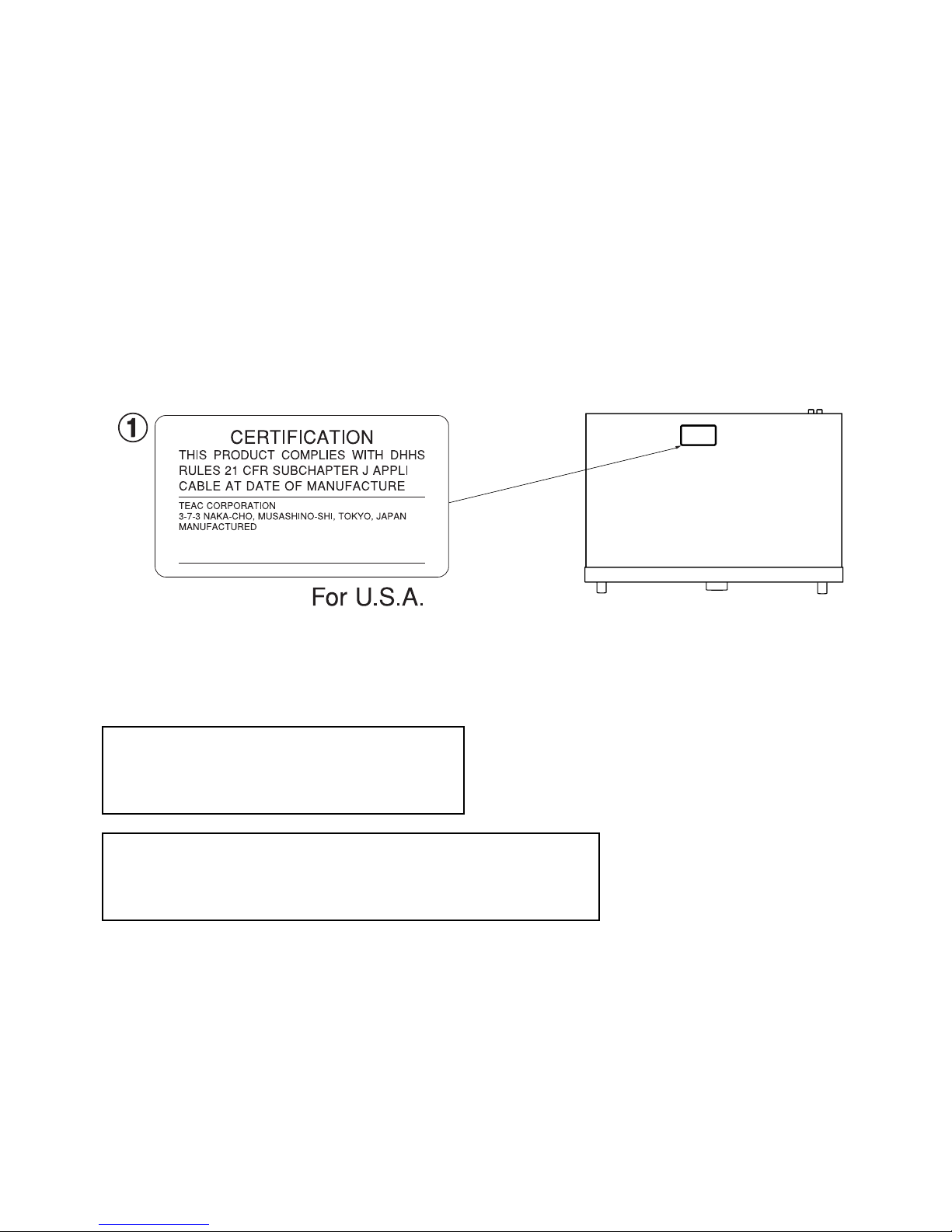
This product has been designed and manufactured according to FDA regulations "title 21, CFR, chapter 1, subchapter J, based on the
Radiation Control for Health and Safety Act of 1968", and is classified as a class 1 laser product. There is no hazardous invisible laser
radiation
during operation because invisible laser radiation emitted inside of this product is completely confined in the protective housings.
The label required in this regulation is shown .
ºCAUTION
USE OF CONTROLS OR ADJUSTMENT OR PERFORMANCE OF PROCEDURES OTHER THAN THOSE SPECIFIED HEREIN MAY RESULT IN
HAZARDOUS RADIATION EXPOSURE.
MD Drive Type : KMS-260E
Optical pickup: Manufacturer : SONY Corporation
Laser output : 4.55 mW
Wavelength : 785+/-20nm
CD Drive Type : KSS-575B
Optical pickup: Manufacturer : SONY Corporation
Laser output : Less than 0.4mW on the objective lens.
Wavelength : 760-780nm
DTA

2. SPECIFICATIONS
仕様
TASCAM MD-CD1 & LA-MC1
MD deck
Type MiniDisc recorder
Discs MiniDisc format
Rec modes Stereo/Mono/LP2/LP4
Recording format Magnetic field modulation overwrite
Recording time 74 minutes (stereo), 148 minutes
(mono), 148 minutes (LP2), 296
minutes (LP4) when using a 74-
minute disc
Sampling frequency 44.1 kHz
Compression system ATRAC (Adaptive Transform
Acoustic Coding)
CD deck
Type Compact Disc player
Discs CD/CD-R/CD-RW
Formats Audio CD (CD-DA), MP3
Rated input/output
Analog line input (MD input)
Connectors RCA
Input level -10 dBV
Input impedance 10 kΩ
Analog line outputs
Connectors RCA
Out put level -10 dBV
Output impedance 570Ω
Headphones
Connectors standard stereo jack
Max. output level 20 mW + 20 mW
Load impedance 32Ω
Digital input TOS (EIAJ RC-5720)
Format IEC60958 Type II (S/PDIF)
Digital output TOS (EIAJ RC-5720)
Format IEC60958 Type II (S/PDIF)
Keyboard Mini DIN 6-pin
MD specifications
Frequency response 20 Hz to 20 kHz +/- 0.5 dB
S/N ratio > 98 dB (playback, A filter),
> 95 dB (recording, A filter)
Dynamic range > 98 dB (playback, A filter),
> 95 dB (recording, A filter)
Total harmonic distortion < 0.004% (playback),
< 0.006% (recording)
Channel separation > 90 dB (playback, at 1 kHz),
> 83 dB (recording, at 1 kHz)
CD specifications
Frequency response 20 Hz to 20 kHz +/- 0.5 dB
S/N ratio > 100 dB (A filter)
Dynamic range > 100 dB (A filter)
Total harmonic distortion < 0.004%
Channel separation > 90 dB (at 1 kHz)
Wow and flutter below measurable limits (less than
0.001%)
MDデッキ部定格
形式 ミニディスクレコーダー
使用ディスク ミニディスク
記録モード STEREO/MONO/LP2/LP4
記録方式 Magneticfieldmodulation
overwrite
録音時間 74分(標準)、148分(MONO)
(74分ディスク使用時) 148分
(LP2)、296分(LP4)
サンプリング周波数 44.1kHz
圧縮方式 ATRAC(AdaptiveTRansform
AcousticCoding)
CDデッキ部定格
形式 CD再生機
使用ディスク CD/CD-R/CD-RW
再生可能フォーマット オーディオCD(CD-DA)、MP3
入出力定格
アナログライン入力(MD入力)
コネクター RCA
規定入力レベル −10dBV
入力インピーダンス 10kΩ
アナログライン出力
コネクター RCA
規定出力レベル −10dBV
出力インピーダンス 570Ω
PHONES
コネクター ステレオホンジャック
最大出力レベル 20mW+20mW
負荷インピーダンス 32Ω
デジタル入力 TOS(EIAJRC-5720)
フォーマット IEC60958Type「 (S/PDIF)
デジタル出力 TOS(EIAJRC-5720)
フォーマット IEC60958Type「 (S/PDIF)
KEYBOARD MiniDIN6p
MD電気的特性
周波数特性 20Hz〜20kHz、± 0.5dB
S/N比 98dB以上
(再生時、Aフィルター)
95dB以上
(録音時、Aフィルター)
ダイナミックレンジ 98dB以上(
再生時、Aフィルター)
95dB以上(
録音時、Aフィルター)
全高調波歪率 0.004%以下(再生時)
0.006%以下(録音時)
チャンネルセパレーション
90dB以上(再生時、1kHz)
83dB以上(録音時、1kHz)
オーディオCD電気的特性
再生周波数特性 20Hz〜20kHz、±0.5dB
S/N比 100dB以上(Aフィルター)
ダイナミックレンジ 100dB以上(Aフィルター)
全高調波歪率 0.004%以下
チャンネルセパレーション 90dB以上(1kHz)
ワウフラッター 測定限界以下(0.001%以下)
−3−

−4−
TASCAM MD-CD1 & LA-MC1
Unit specifications
Power USA/Canada 120 VAC, 60 Hz
U.K./Europe 230 VAC, 50 Hz
Australia 240 VAC, 50 Hz
Power consumption 18 W
Dimensions 483 x 94 x 308 mm
19 x 3.7 x 12.1 (in)
Weight 5.8 kg (12.8 lbs)
Operating temperature range Operating temperature range: 5 to
40 degrees C (41°F to 104°F)
Supplied accessories remote control unit (1)
AA batteries (2)
power cord (1)
rack-mounting kit (1)
owner's manual (1)
warranty (1)
For product improvement, specifications and external appearance
are subject to change without notice.
Due to product improvement, the actual unit may appear
differently than the illustrations in the operation manual.
一般
電源 AC100V、50/60Hz
消費電力 18W
外形寸法 483x94x308(mm)
質量 5.8kg
動作温度 5〜40℃
付属品 リモコン(x1)
単三電池(x2)
電源コード(x1)
取扱説明書(x1)
ラックマウントビスキット(x1)
保証書(x1)
* EIAJは日本電子機械工業会規格に定められた測定法によ
るものです。
* 仕様および外観は、改善のため予告なく変更することがあ
ります。
* 製品の改善により、取扱説明書のイラストなどが、一部製
品と異なることがあります。あらかじめご了承ください。
Dimensional drawing
外形寸法図
18 mm
308 mm
285 mm
5 mm
483 mm
465 mm
435 mm
76 mm
88 mm
94 mm
−5−
3. Test Mode
テストモード
TASCAM MD-CD1 & LA-MC1
3-1. How to set the test mode enabled
While holding down the OPEN/CLOSE and EJECT keys, switch on
the power.
(You need to keep both keys held down until the display reads
"Test Mode".)
To turn the test mode off, switch off the power.
3-2. Test mode menu
When running in test mode, the center encoder is available for
selecting test items and confirming your selection.
The following items are available:
[DISPLAY CHK]
[KEY CHECK]
[ENCODER CHK]
[CONT SW CHK][
KEYBOARD CHK]
[RS-232C CHK]
[EEP CHECK]
[MD ADJUST]
This procedure is applicable for MD-CD system
microcomputer version 1.10 and above.
[VERSION UP]
[VERSION CHK]
When an item is selected and you press the CD STOP key, you
will go back to the test mode menu.
3-3. Test items explained
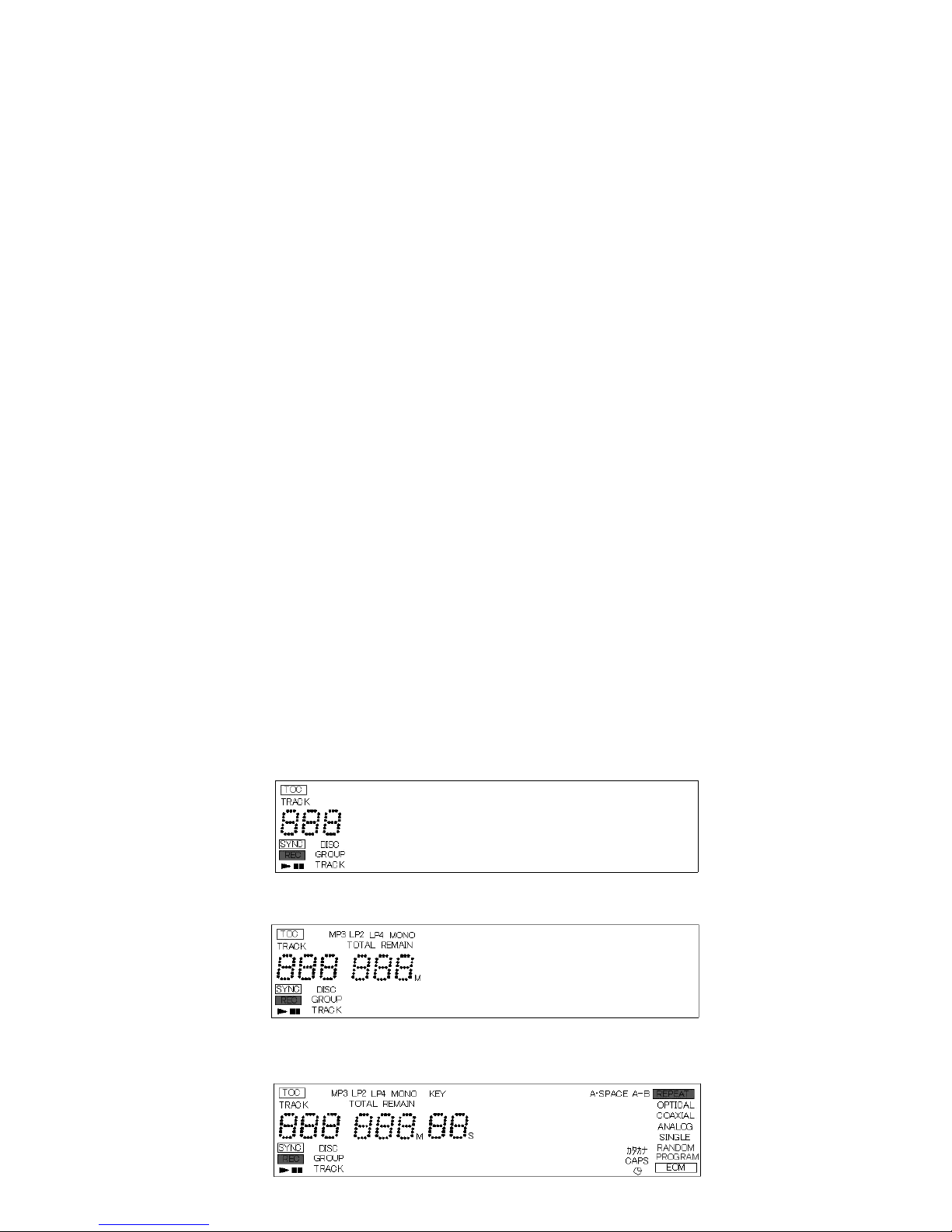
1) DISPLAY CHK
With each press of the DISPLAY key, the FL display tube shows
grids and characters as shown below, with LEDs being on or off:
To turn off this selection, press the CD STOP key.
1st stage: FL display tube and all LEDs turned off
2nd stage:
3-1.テストモードへの入り方
「OPEN/CLOSE」と「EJECT」キーを押しながら電源を投
入する。
(ディスプレイに「TestMode」と表示するまで押し続ける)
テストモードは電源OFFで終了する。
3-2.テストモードメニュー
テストモードに入ったら、センターエンコーダでテスト項目
を選択、決定する。
選択項目は以下の通りである。
「DISPLAYCHK」
「KEYCHECK」
「ENCODERCHK」
「CONTSWCHK」
「KEYBOARDCHK」
「RS-232CCHK」
「EEPCHECK」
「MDADJUST」
本手順は、MD-CD1 システムマイコン Ver.1.10
以降に適用されます。
「VERSIONUP」
「VERSIONCHK」
選択状態でCD側「STOP」キーを押すことで選択項目に戻
る。
3-3.各テストモードの説明
1)DISPLAYCHK
「DISPLAY」キーを押す毎に、下記の様にFL管にGRID、キ
ャラクター部を表示し、LEDが点灯もしくは消灯する。
「CDSTOP」キーにてテストモード終了する。
第1段階はFL管消灯、LED全消灯。
第2段階
3rd stage:
4th stage:
第3段階
第4段階
−6−
TASCAM MD-CD1 & LA-MC1
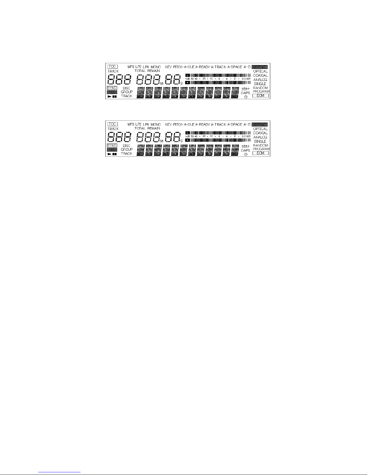
第5段階
第6段階
第7段階
FL管全点灯+CD側LED全点灯
第8段階
FL管全点灯+LED全点灯
再度「DISPLAY」キーを押すとDISPLAYCHKを終了する。
2)KEYCHECK
FL管に表示されたキーを順次押してチェックを行う。最後ま
でキーチェックしないと、このテストモードから抜けること
は出来ません。
3)ENCODERCHK
FL管にて操作するべきエンコーダーと方法が表示される。順
番は
(1)「センターエンコーダーの左回し、クリック3回分」
(2)「センターエンコーダーの右回し、クリック3回分」
(3)「センターエンコーダーのプッシュ」
(4)「CD側エンコーダーの左回し、クリック3回分」
(5)「CD側エンコーダーの右回し、クリック3回分」
(6)「CD側エンコーダーのプッシュ」
(7)「MD側エンコーダーの左回し、クリック3回分」
(8)「MD側エンコーダーの右回し、クリック3回分」
(9)「MD側エンコーダーのプッシュ」
(10)「CDSTOP」キーでテストモードは終了する。
4)CONTSWCHK
現在の位置を表示する。
ON側にある場合は「CONTSWON」、OFF側にある場合は
「CONT SW OFF」と表示し、両方表示されることを確認す
る。
5th stage:
6th stage:
7th stage: FL display tube turned on and all LEDs light up on CD
player
8th stage: FL display tube and all LEDs turned on
Press again the DISPLAY key to terminate DISPLAY CHK.
2) KEY CHECK
Press keys in sequence as the FL display tube shows.
Unless you sequence through all keys, you cannot quit this mode.
3) ENCODER CHK
The FL display tube shows how to operate which encoder in this
order:
(1)Rotate the center encoder counterclockwise over a distance
of 3 clicks.
(2)Rotate the center encoder clockwise over a distance of 3
clicks.
(3)Push the center encoder.
(4)Rotate the CD-side encoder counterclockwise over a
distance of 3 clicks.
(5)Rotate the CD-side encoder clockwise over a distance of 3
clicks.
(6)Push the CD-side encoder.
(7)Rotate the MD-side encoder counterclockwise over a
distance of 3 clicks.
(8)Rotate the MD-side encoder clockwise over a distance of 3
clicks.
(9)Push the MD-side encoder.
(10) Press the CD STOP key to quit this mode.
4) CONT SW CHK
This shows the current control switch position.
Set the control switch to ON and OFF to check to see if "CONT SW
ON" and "CONT SW OFF" are displayed, respectively.

−7−
TASCAM MD-CD1 & LA-MC1
5)KEYBOARDCHK
「KEY CHECK」と同様にFL管に表示しているキーを押す。
「KEY CHECK」と異なりすべてのキーをチェックする必要
はない。
6)RS-232CCHK
RS-232Cの送受信をループ治具で確認を行う。
「DataSend?」表示中に、「ENTER」キーで実行する。
OK:「RS-232CGood」
NG:「TimeOut!!」
上記、どちらかを表示する。
注意: ループ治具での確認時、「ENTER」キーで実行する前
にループ治具のRx端子にRS-232Cレベル電圧の印
可を行う事。
7)EEPCHECK
(1)「DEFAULTJPN」
DM用のEEPROMの初期化設定。工場出荷用。
(2)「DEFPARAJPN」
DM用のEEP ROMの初期化設定。ただし、再生時間、
記録時間の積算時間は初期化しない。
(3)「DEFAULTUS」
DM以外のEEPROMの初期化設定。工場出荷用。
(4)「DEFPARAUS」
DM以外のEEPROMの初期化設定。ただし、再生時間、
記録時間の積算時間は初期化しない。
(5)「CLRTIMECD」
仕向けに関係なくCDの再生積算時間だけの初期化。サ
ービスにてCDドライブを交換したときに使用。
(6)「CLRTIMEMD」
仕向けに関係なくMDの再生&記録積算時間だけの初期
化。サービスにてMDメカを交換したときに使用。
8)MDADJUST
MDメカのサーボ調整を実行する。
調整項目
(1) 温度補正オフセット調整 「TEMPADJUST」
(2) レーザーパワー調整 「LDPWRADJUST」
(3) レーザーパワー確認 「LDPWRCHECK」
(4) EFバランス調整 「EFBALADJUST」
(5) フォーカスバイアスの調整 「FBIASADJUST」
(6) フォーカスバイアスの確認 「FBIASCHECK」
(7) テスト再生 「CPLAYMODE」
(8) テスト録音 「CRECMODE」
上記の項目が調整、確認可能である。
MD メカのサーボ調整の詳細については、「MD メカ サーボ
調整手順」を参照。
5) KEYBOARD CHK
As with KEY CHECK, press keys as the FL display tube shows.
Unlike with KEY CHECK, you don't need to check all keys.
6) RS-232C CHK
This checks data send/receive through RS-232C using a loop jig.
To get the check process started, press the ENTER key when
"Data Send?" is displayed.
Depending on whether the check is successful or not, either of
the following will be displayed:
OK : "RS-232C Good"
NG : "Time Out!!"
NOTE: Before pressing the ENTER key, be sure to apply an RS-
232C level voltage to the Rx terminal of a loop jig.
7) EEP CHECK
(1)[DEFAULT JPN]
Initial setting of EEP ROM for Japan. For use before
shipment.
(2)[DEF PARA JPN]
Initial setting of EEP ROM for Japan. Total play and record
times not initialized.
(3)[DEFAULT US]
Initial setting of EEP ROM for other countries than Japan.
For use before shipment.
(4)[DEF PARA US]
Initial setting of EEP ROM for other countries than Japan.
Total play and record times not initialized.
(5)[CLR TIME CD]
Initialization of total CD play time only, regardless of
destination country. For use when CD drive is replaced in
servicing process.
(6)[CLR TIME MD]
Initialization of total MD play and record times only,
regardless of destination country. For use when MD
mechanism is replaced in servicing process.
8) MD ADJUST
This adjusts the servo of MD mechanism.
Adjustment items
The following adjustments and checks are provided.
(1) Temperature correcting offset adjustment
[TEMP ADJUST]
(2) Laser power adjustment [LDPWR ADJUST]
(3) Laser power check [LDPWR CHECK]
(4) EF balance adjustment [EFBAL ADJUST]
(5) Focus bias adjustment [FBIAS ADJUST]
(6) Focus bias check [FBIAS CHECK]
(7) Test play [CPLAY MODE]
(8) Test record [CREC MODE]
For details on how to adjust the servo of MD mechanism, refer to
"Procedure for adjusting servo of MD mechanism".

−8−
TASCAM MD-CD1 & LA-MC1
9)VERSIONUP
FLASHROMのバージョンアップを実行する。
バージョンアップ元のファイルはボリュームラベル
「UPDATE」、ファイル名「FLASH.MOT」にして、ディス
クに記録しておく。(ファイル名は「MDCD1xxxx.MOT」
でも可能。「xxxx」部は数字を推奨。)
「VERSION UP」と表示されている状態で「ENTER」キー
を押す。トレイが自動的にオープンするので(表示は「Disc
Set」)準備したディスクをトレイに乗せ「OPEN/CLOSE」
キーでトレイを閉める。(手動でトレイを閉めることも可能で
ある。)
「File Check」と表示中に挿入されたディスクをチェックし、
アップデートファイルと認識すると「Update?」と表示する
ので「ENTER」キーで実行する。
実行中はFLASH ROMの書き込みセクタナンバーを表示し
「Complete」表示で終了となる。
バージョンアップ後は電源を入れ直して再起動してください。
10)VERSIONCHK
センターエンコーダーを回すことにより、下記が表示されま
す。
「SYSVerxx.xx」
「CDVerxx.xx」
「MDVerxx.xx」
「BUILDxxxxx」
3-4.テストモード終了
テストモードは電源OFFで終了する。
9) VERSION UP
This gets FLASH ROM updated.
Give a volume label "UPTATE" and a file name "FLASH.MOT" to the
update-from file and record this file on a disc. (For the file name,
"MDCD1_xxxx.MOT" is also available. We recommend entering
numerals in "xxxx".)
Press the ENTER key when "VERSION UP" is displayed. The tray
will automatically slide out ("Disc Set" is displayed). Place the disc
carrying the update-from file copy in the tray and press the
OPEN/CLOSE key to close the tray. (You can also manually close
the tray.)
The loaded disc is checked while "File Check" is displayed. When
the disk is identified as an update file, "Update?" is displayed.
Then press the ENTER key to get the update process started.
As the update process goes on, the display shows write sector
numbers of FLASH ROM, and when the process is over,
"Complete" is displayed.
After updated, recycle the power.
NOTE: Use the "Disc at once" function to create a disc for update.
10) VERSION CHK
As you rotate the center encoder, the following are displayed:
[SYS Ver xx.xx]
[CD Ver xx.xx]
[MD Ver xx.xx]
[BUILD xxxxx]
3-4. Switching off test mode
Switch off the power.

−9−
4.
PROCEDURE FOR ADJUSTING SERVO OF MD MECHANISM
MDメカ サーボ調整手順
TASCAM MD-CD1 & LA-MC1
This procedure is applicable for MD-CD system microcomputer
version 1.10 and above.
4-1. Requirements
º Measuring instrument
Oscilloscope : 100 MHz or higher
Laser power meter : Leader's LPM-8001
(or equivalent with a maximum of
10mW range)
Jitter meter for MD : Leader's LJM-1851
(or equivalent with a range of ™≈
Sigma 30ns)
ÚWe recommend using a jitter meter for accuracy in "Focus bias
adjustment", "Checking jitter in self-record/play of MO Discs",
and "Checking jitter in play of Pit Discs". If no jitter meter is
available, refer to C1 error rate displayed on the unit.
º Test disc
Test Disc MMD-111 (P/N 49001622-00 : MO disc for
adjustment and checking)
Test Disc MMD-211 (P/N 49001524-00 : Pit disc for
adjustment and checking 1)
SONY's MDW-74A or equivalent (Recordable blank disc)
º Entering test mode
While holding down the OPEN/CLOSE and EJECT keys, switch
on the power.
(You need to hold down both keys until "Test Mode" is
displayed.)
º Terminating test mode
Switch off the power.
º Selecting test mode options
Select options with the multi-jog and press the ENTER key to
confirm your selection. Press the CD STOP key to turn off your
selection.
The use of other specific keys is referred to where necessary.
º MD mechanism assembly
1) Remove the MD mechanism assembly from the unit and
place it at a spot favorable for adjustments (on a board
placed on the unit, for example).
2) Remove flap.
ÚA spot favorable for adjustments refers to a spot where it is
easy to insert the laser power meter's light receptacle so far as
to reach just above the pickup lens.
ÚThe flap can easily be removed by opening the leaf spring
outward which is located at the right side of the flap viewed
from the front.
本手順は、MD-CD1 システムマイコン Ver.1.10以降に適
用されます。
4-1.準備
● 使用する測定器
オシロスコープ :100MHz以上
レーザーパワーメータ :Leader社製LPM-8001
(または相当品。最大10mWレ
ンジのある物)
MD用ジッターメータ :Leader社製LJM-1851
(または相当品。↑↓Sigma
30nsレンジのある物)
※「フォーカスバイアスの調整」、「MO Discの自己録再ジ
ッター確認」、および「Pit Discの再生ジッター確認」の
正確な調整を行うには、ジッターメータの使用を推奨する。
ジッターメータが無い場合、本体に表示されるC1エラー
レートの値を用いて調整して下さい。
● テストディスク
TestDiscMMD-111
(P/N49001622-00:MOdiscfor adjustment
andchecking)
TestDiscMMD-211
(P/N 49001524-00:Pit disc for adjustment
andchecking1)
SONYMDW-74Aまたは相当品
(Recordableblankdisc)
● テストモードへの入り方
「OPEN/CLOSE」と「EJECT」キーを押しながら電源を
投入する。(ディスプレイに「Test Mode」と表示するま
で押し続ける)
● テストモードの解除
電源を切る。
● テストモードの選択
「MULTIJOG」で選択、「ENTER」で決定、「CDSTOP」
で選択項目の解除を行います。
他、各項目での特殊キーについては使用項目で説明します。
● MDメカ Assy
1) MDメカAssyを本体から取り外し、調整しやすい位
置に置いて下さい。(例:本体の上に板を敷き、その
上にメカ Assyを置く)
2) フラップを外して下さい。
※ 調整しやすい位置とは、レーザーパワーメータ受光部をピ
ックアップレンズ真上まで挿入しやすい位置を意味しま
す。
※ フラップは、正面から見てフラップの右側にある板バネを
外側に開く事により、簡単に外す事ができます。
−10−
TASCAM MD-CD1 & LA-MC1
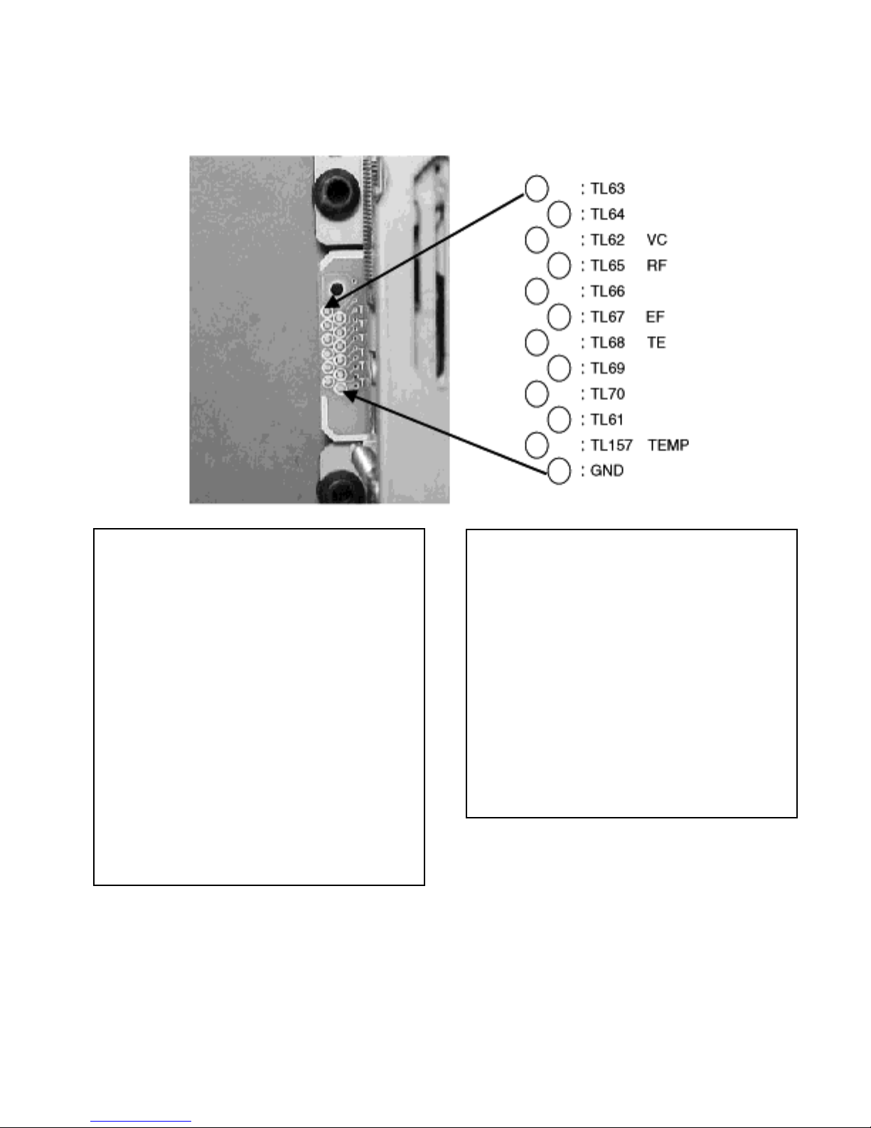
4-2.テストポイント
4-2 .Test points
注意事項
1.レーザーダイオードが発光している時は、絶対にピ
ックアップを真上から覗かないで下さい。真上から
覗くと、失明のおそれがあります。
2.使用する測定器は、2極の電源プラグで使用して下
さい。3極の場合は2極に変換して下さい。
3.調整基準電圧はVcなので、GNDとショートさせな
いようにして下さい。(各機器のGND端子を、Vcと
GNDおよびシャーシに同時に接続しないで下さい。
4.ピックアップAssy、ControlBLKPCBAssyの交
換を行った場合のみ本調整を行い、それ以外の場合
には絶対に行わないで下さい。
5.調整を行う場合、24℃〜26℃の環境下で行って下
さい。
Warning
1. When the laser diode is emitting light, never take a look
at the pickup from directly above. If you do, there is the
danger of going blind.
2. Use a two-prong electrical plug for connection of
measuring instruments to a power outlet. A three-prong
plug should be converted to a two-prong plug.
3. The adjustment reference voltage is available at Vc So
avoid shorting Vc to ground. (Don't connect the GND
terminal of each instrument to Vc and ground or
chassis at the same time.)
4. Make adjustments described below only when the
pickup assembly or the control BLK PCB assembly are
replaced. Never make these adjustments in any other
cases.
5. Adjustments should be made in an environment where
the temperature is between 24 and 26 degrees
Centigrade.

−11−
TASCAM MD-CD1 & LA-MC1
4-3. Adjustments
º Temperature correcting offset adjustment ("TEMP ADJUST")
1) With the TEMP and GND terminals shorted with a jumper
wire, enter Test mode.
2) Using the multi-jog and the ENTER key, select "MD ADJUST"
∑ "TEMP ADJUST", and press the ENTER key to save data.
3) Switch off the power and remove the jumper wire from the
TEMP and GND terminals.
ÚThis adjustment should be made when the temperature inside
the unit is the same as the ambient temperature, that is,
immediately after applying power to the unit.
º Laser power adjustment ("LDPWR ADJUST")
When "LDPWR ADJUST" is displayed, press the ENTER key and
"LD Adjust x 1" is displayed. When "LD Adjust x 1" is displayed,
rotating the multi-jog allows you to select "LD Adjust x 4".
Normally, first make the x1 adjustment, then the x4
adjustment.
Making the x1 adjustment affects the x4 settings. Be sure to
make both the x1 and x4 adjustments.
Pressing the CD STOP key in the process of adjustment
interrupts the process, bringing you back to "MD ADJUST".
If you interrupt the process, re-do adjustment.
¤ 1X speed adjustment
When "LD Adjust x1" is displayed, press the ENTER key and
"1/2 Write ON?" is displayed.
1 1/2 Write adjustment (1X speed "1/2 Write ON?")
1) Set a laser power meter to 10mW range, and insert its
light receptacle so that it becomes above the pickup of
the MD mechanism assembly.
2) When "1/2 Write ON?" is displayed, press the ENTER key
and the laser starts emitting light. (The display changes to
read "1/2 Wr x1=xxx".)
3) Rotate the multi-jog so that the laser power meter
registers 3.2 mW.
4) When the meter registers the correct value, press the
ENTER key to save data and the laser stops emitting light.
(The display changes to read "Pit Read ON?")
4-3.調整
● 温度補正オフセット調整(「TEMPADJUST」)
1) TEMP端子とGND端子をジャンパー線でショートし
た状態で、テストモードにして下さい。
2)「MULTI JOG」、「ENTER」キーを使い、「MD
ADJUST」∑ 「 TEMP ADJUST」を選択し、
「ENTER」キーを押すと、データがセーブされます。
3) 電源を切り、1)で接続したジャンパー線を外して下
さい。
※ 本調整は、セット内部の温度が周囲温度と同じである、電
源投入直後に行って下さい。
● レーザーパワー調整(「LDPWRADJUST」)
「LDPWRADJUST」表示中に「ENTER」キーを押すと、
「LDAdjustx1」を表示します。「LDAdjustx1」を表
示中に「MULTI JOG」を回すと、「LDAdjust x4」の
選択を行う事ができます。
通常、1倍速を調整後に4倍速の調整を行って下さい。
1倍速の調整を行うと4倍速の設定値も変更されるため、
必ず1倍、4倍ともに調整を行って下さい。
調整途中で、「CD STOP」キーを押すと、調整を中断し
「MDADJUST」に戻ります。
途中で中断した場合、再度調整を行って下さい。
★ 1倍速の調整
「LD Adjust x1」を表示中に「ENTER」キーを押す
と、「1/2WriteON?」を表示します。
1 1/2Writeの調整(1倍速「1/2WriteON?」)
1)レーザーパワーメータを10mWレンジにセットし、
受光部をMDメカAssyのピックアップ上部に挿入し
て下さい。
2)「1/2Write ON?」表示中に「ENTER」キーを
押すと、レーザーが発光状態となります。(「1/
2Wrx1=xxx」)
3)レーザーパワーメータの値が3.2mWになるように
「MULTIJOG」を回して調整を行って下さい。
4)適正な値に調整後、「ENTER」キーを押すと、デー
タをセーブし、レーザーが消灯状態となります。
(「PitReadON?」を表示します。)

−12−
TASCAM MD-CD1 & LA-MC1
2 Pit Read adjustment (1X speed "Pit Read ON?")
1) Set the laser power meter to 1mW range, and insert its
light receptacle so that it becomes above the pickup of
the MD mechanism assembly.
2) When "Pit Read ON?" is displayed, press the ENTER key
and the laser starts emitting light. (The display changes to
read "Pit Read=xxx".)
3) Rotate the multi-jog so that the laser power meter
registers 0.66 mW.
4) When the meter registers the correct value, press the
ENTER key to save data and the laser stops emitting light.
(The display changes to read "Groove ON?")
3 Groove Read adjustment (1X speed "Groove ON?")
1) Set the laser power meter to 1mW range, and insert its
light receptacle so that it becomes above the pickup of
the MD mechanism assembly.
2) When "Groove ON?" is displayed, press the ENTER key
and the laser starts emitting light. (The display changes to
read "Groove=xxx".)
3) Rotate the multi-jog so that the laser power meter
registers 0.85 mW.
4) When the meter registers the correct value, press the
ENTER key to save data and the laser stops emitting light.
(The display changes to read "LD Adjust x4".)
¤ 4X Speed Adjustments
When "LD Adjust x4" is displayed, press the ENTER key and
"1/2 Write ON?" is displayed.
4 1/2 Write adjustment (4X speed "1/2 Write ON?")
1) Set the laser power meter to 10 mW range, and insert its
light receptacle so that it becomes above the pickup of
the MD mechanism assembly.
2) When "1/2 Write ON?" is displayed, press the ENTER key
and the laser starts emitting light. (The display changes to
read "1/2 Wr x4=xxx".)
3) Rotate the multi-jog so that the laser power meter
registers 4.0 mW.
4) When the meter registers the correct value, press the
ENTER key to save data and the laser stops emitting light.
(This brings you back to "LDPWR ADJUST".)
2 PitReadの調整(1倍速「PitReadON?」)
1)レーザーパワーメータを1mWレンジにセットし、
受光部をMDメカAssyのピックアップ上部に挿入し
て下さい。
2)「Pit Read ON?」表示中に「ENTER」キーを押
すと、レーザーが発光状態となります。(「Pit
Read=xxx」)
3)レーザーパワーメータの値が0.66mWになるように
「MULTIJOG」を回して調整を行って下さい。
4)適正な値に調整後、「ENTER」キーを押すと、デー
タをセーブし、レーザーが消灯状態となります。
(「GrooveON?」を表示します。)
3 GrooveReadの調整(1倍速「GrooveON?」)
1)レーザーパワーメータを1mWレンジにセットし、
受光部をMDメカAssyのピックアップ上部に挿入し
て下さい。
2)「Groove ON?」表示中に「ENTER」キーを押す
と、レーザーが発光状態となります。
(「Groove=xxx」)
3)レーザーパワーメータの値が0.85mWになるように
「MULTIJOG」を回して調整を行って下さい。
4)適正な値に調整後、「ENTER」キーを押すと、デー
タをセーブし、レーザーが消灯状態となります。
(「LDAdjustx4」を表示します。)
★ 4倍速の調整
「LD Adjust x4」を表示中に「ENTER」キーを押す
と、「1/2WriteON?」を表示します。
4 1/2Writeの調整(4倍速「1/2WriteON?」)
1)レーザーパワーメータを10mWレンジにセットし、
受光部をMDメカAssyのピックアップ上部に挿入し
て下さい。
2)「1/2Write ON?」表示中に「ENTER」キーを
押すと、レーザーが発光状態となります。(「1/
2Wrx4=xxx」)
3)レーザーパワーメータの値が4.0mWになるように
「MULTIJOG」を回して調整を行って下さい。
4)適正な値に調整後、「ENTER」キーを押すと、デー
タをセーブし、レーザーが消灯状態となります。
(「LDPWRADJUST」に戻ります。)

−13−
TASCAM MD-CD1 & LA-MC1
º Checking laser power ("LDPWR CHECK")
When "LDPWR CHECK" is displayed, press the ENTER key and
"Pit Read" is displayed. When "Pit Read" is displayed, rotating
the multi-jog selects "Write Level 1", "Groove Read", "1/2 Write
1", "Write Level 4", and "1/2 Write 4".
Pressing the CD STOP key in the process of check interrupts
the process, bringing you back to "MD ADJUST".
● レーザーパワー確認(「LDPWRCHECK」)
「LDPWR CHECK」表示中、「ENTER」キーを押すと、
「PitRead」を表示します。「Pit Read」を表示中、
「MULTI JOG」を回すと、「WriteLevel1」、「Groove
Read」、「1/2Write1」、「Write Level4」、「1/
2Write4」の選択を行う事ができます。
確認途中で、「 CD STOP」キーを押すと、「MD
ADJUST」に戻ります。
注意事項
レーザーダイオード保護の為、各レベルの確認は10秒
以内で終了する事。
1 PitReadの確認(1倍速「PitRead」)
1)レーザーパワーメータを1mWレンジにセットし、
受光部をMDメカAssyのピックアップ上部に挿入し
て下さい。
2)「PitRead」表示中に「ENTER」キーを押すと、
レーザーが発光状態となります。(「PitRead=xxx」)
3)レーザーパワーメータの値が0.66mW付近である事
を確認して下さい。
4)「ENTER」キーを押すと、レーザーが消灯状態とな
ります。(「GrooveRead」を表示します。)
2 GrooveReadの確認(1倍速「GrooveRead」)
1)レーザーパワーメータを1mWレンジにセットし、
受光部をMDメカAssyのピックアップ上部に挿入し
て下さい。
2)「Groove Read」表示中に「ENTER」キーを押す
と、レーザーが発光状態となります。
(「Groove=xxx」)
3)レーザーパワーメータの値が0.85mW付近である事
を確認して下さい。
4)「ENTER」キーを押すと、レーザーが消灯状態とな
ります。(「WriteLevel1」を表示します。)
3 Writeの確認(1倍速「WriteLevel1」)
1)レーザーパワーメータを10mWレンジにセットし、
受光部をMDメカAssyのピックアップ上部に挿入し
て下さい。
2)「Write Level1」表示中に「ENTER」キーを押す
と、レーザーが発光状態となります。(「Write
x1=xxx」)
3)レーザーパワーメータの値が6.5mW付近である事を
確認して下さい。
4)「ENTER」キーを押すと、レーザーが消灯状態とな
ります。(「1/2Write1」を表示します。)
Caution:
To protect the laser diode, checking at each level should
be completed within 10 seconds.
1 Checking Pit Read (1X speed "Pit Read")
1) Set the laser power meter to 1mW range, and insert its
light receptacle so that it becomes above the pickup of
the MD mechanism assembly.
2) When "Pit Read" is displayed, press the ENTER key and
the laser starts emitting light. (The display changes to
read "Pit Read=xxx".)
3) Check to see that the laser power meter registers 0.66
mW or so.
4) Press the ENTER key and the laser stops to emit light.
(The display changes to read "Groove Read".)
2 Checking Groove Read (1X speed "Groove Read")
1) Set the laser power meter to 1mW range, and insert its
light receptacle so that it becomes above the pickup of
the MD mechanism assembly.
2) When "Groove Read" is displayed, press the ENTER key
and the laser starts emitting light. (The display changes to
read "Groove=xxx".)
3) Check to see that the laser power meter registers 0.85
mW or so.
4) Press the ENTER key and the laser stops to emit light.
(The display changes to read "Write Level 1".)
3 Checking Write (1X speed "Write Level 1")
1) Set the laser power meter to 10 mW range, and insert its
light receptacle so that it becomes above the pickup of
the MD mechanism assembly.
2) When "Write Level 1" is displayed, press the ENTER key
and the laser starts emitting light. (The display changes to
read "Write x1=xxx".)
3) Check to see that the laser power meter registers 6.5 mW
or so.
4) Press the ENTER key and the laser stops to emit light.
(The display changes to read "1/2 Write 1".)

−14−
TASCAM MD-CD1 & LA-MC1
4 Checking 1/2 Write (1X speed "1/2 Write 1")
1) Set the laser power meter to 10 mW range, and insert its
light receptacle so that it becomes above the pickup of
the MD mechanism assembly.
2) When "1/2 Write 1" is displayed, press the ENTER key and
the laser starts emitting light. (The display changes to
read "1/2 Wr x1=xxx".)
3) Check to see that the laser power meter registers 3.2 mW
or so.
4) Press the ENTER key and the laser stops to emit light.
(The display changes to read "Write Level 4".)
5 Checking Write (4X speed "Write Level 4")
1) Set the laser power meter to 10 mW range, and insert its
light receptacle so that it becomes above the pickup of
the MD mechanism assembly.
2) When "Write Level 4" is displayed, press the ENTER key
and the laser starts emitting light. (The display changes to
read "Write x 4=xxx".)
3) Check to see that the laser power meter registers 8.1 mW
or so.
4) Press the ENTER key and the laser stops to emit light.
(The display changes to read "1/2 Write 4".)
6 Checking 1/2 Write (4X speed "1/2 Write 4")
1) Set the laser power meter to 10 mW range, and insert its
light receptacle so that it becomes above the pickup of
the MD mechanism assembly.
2) When "1/2 Write 4" is displayed, press the ENTER key and
the laser starts emitting light. (The display changes to
read "1/2 Wr x4=xxx".)
3) Check to see that the laser power meter registers 4.0 mW
or so.
4) Press the ENTER key and the laser stops to emit light.
(This brings you back to "LDPWR CHECK".)
4 1/2Writeの確認(1倍速「1/2Write1」)
1)レーザーパワーメータを10mWレンジにセットし、
受光部をMDメカAssyのピックアップ上部に挿入し
て下さい。
2)「1/2Write 1」表示中に「ENTER」キーを押す
と、レーザーが発光状態となります。(「1/2Wrx1
=xxx」)
3)レーザーパワーメータの値が3.2mW付近である事を
確認して下さい。
4)「ENTER」キーを押すと、レーザーが消灯状態とな
ります。(「WriteLevel4」を表示します。)
5 Writeの確認(4倍速「WriteLevel4」)
1)レーザーパワーメータを10mWレンジにセットし、
受光部をMDメカAssyのピックアップ上部に挿入し
て下さい。
2)「Write Level4」表示中に「ENTER」キーを押す
と、レーザーが発光状態となります。(「Writex4
=xxx」)
3)レーザーパワーメータの値が8.1mW付近である事を
確認して下さい。
4)「ENTER」キーを押すと、レーザーが消灯状態とな
ります。(「1/2Write4」を表示します。)
6 1/2Writeの確認(4倍速「1/2Write4」)
1)レーザーパワーメータを10mWレンジにセットし、
受光部をMDメカAssyのピックアップ上部に挿入し
て下さい。
2)「1/2Write 4」表示中に「ENTER」キーを押す
と、レーザーが発光状態となります。(「1/2Wr
x4=xxx」)
3)レーザーパワーメータの値が4.0mW付近である事を
確認して下さい。
4)「ENTER」キーを押すと、レーザーが消灯状態とな
ります。(「LDPWRCHECK」に戻ります。)
−15−
TASCAM MD-CD1 & LA-MC1
º EF balance adjustment ("EFBAL ADJUST")
Connect an oscilloscope's GND to the Vc terminal and the
probe to the EF terminal, and set the probe for DC coupling.
When "EFBAL ADJUST" is displayed, press the ENTER key and
"Rec Disc Set" is displayed.
When the EJECT key is pressed and a disc is loaded, the disc is
ejected.
In the process of adjustment, pressing the CD STOP key
interrupts the process and brings you back to "MD ADJUST".
If you interrupt the process, re-do adjustment.
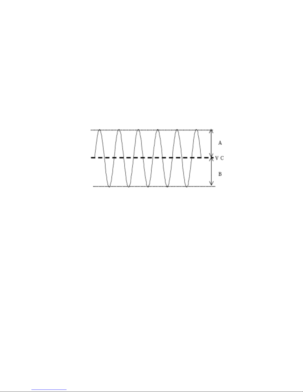
Make each adjustment so that the A and B amplitudes are
identical as far as possible centered around Vc, as the
waveform below shows.
●EFバランス調整(「EFBALADJUST」)
オシロスコープのGNDをVc端子、プローブをEF端子に接
続し、プローブのカップリングはDCに設定して下さい。
「EFBAL ADJUST」表示中に「ENTER」キーを押すと、
「RecDiscSet」を表示します。
「EJECT」キーを押すと、Discが挿入されている場合、
Discの排出を行います。
調整途中で、「CD STOP」キーを押すと、調整を中断し
「MDADJUST」に戻ります。
調整を中断した場合、再度調整を行って下さい。
各調整は、波形が下図のように、Vcを中心にA=Bに一番
近い値に振れるように調整を行って下さい。
★ 1倍速MOの調整
1 MO記録時の調整(1倍速「EFBWritex1」)
1)「Rec Disc Set」表示したら、SONY MDW-74
または相当品を挿入して下さい。
2)Disc読み込み後、「ENTER」キーを押すと、「EFB
Write x1」を表示します。この時、Discが挿入さ
れていないと、「ENTER」キーを押しても表示は変
わりません。また、Recordable Disc以外が挿入さ
れた、または、録音防止窓が記録可能状態で無い場
合、以降の調整が正常に行えません。
3)「EFBWritex1」表示中に「ENTER」キーを押す
と、数秒後に「EFB=$xxWR1」を表示します。
4)「MULTIJOG」を回して、調整を行って下さい。
5)適正な値に調整後、「ENTER」キーを押すと、デー
タをセーブし、停止します。(「EFBGroovex1」を
表示します。)
2 MO再生時の調整(1倍速「EFBGroovex1」)
1)1に続き、「EFB Groovex1」表示中に「ENTER」
キーを押すと、数秒後に「EFB=$xx GRV1」を表
示します。
2)「MULTIJOG」を回して、調整を行って下さい。
3)適正な値に調整後、「ENTER」キーを押すと、デー
タをセーブし、停止します。(「EFBMO-TOCx1」
を表示します。)
¤ 1X speed MO adjustment
1 MO-in-record adjustment (1X speed "EFB Write x1")
1) When "Rec Disc Set" is displayed, insert SONY MDW-74
or equivalent disc.
2) When the disc is loaded, press the ENTER key and "EFB
Write x 1" is displayed. If no disc is present, pressing the
ENTER key has no effect on the display. Also, the
following adjustments cannot be made properly if other
media than Recordable Discs are inserted or the disc is
write-protected.
3) When "EFB Write x1" is displayed, press the ENTER key
and "EFB=$xx WR 1" is displayed in several seconds.
4) Make adjustment by rotating the multi-jog.
5) After making adjustment for a proper value, press the
ENTER key to save data and complete the process. (The
display changes to read "EFB Groove 1".)
2 MO-in-play adjustment (1X speed "EFB Groovex 1")
1) When "EFB Groovex 1" is displayed as a result of
completing process 1, press the ENTER key and "
EFB=$xx GRV 1" is displayed in several seconds.
2) Rotate the multi-jog to make adjustment.
3) When adjustment is made for a proper value, press the
ENTER key to save data and complete the process. (The
display changes to read "EFB MO-TOCx 1".)

−16−
TASCAM MD-CD1 & LA-MC1
3 MO P-TOC adjustment (1X speed "EFB MO-TOCx 1")
1) When "EFB MO-TOCx 1" is displayed as a result of
completing process 2 , press the ENTER key and
"EFB=$xx M-P1" is displayed.
2) Rotate the multi-jog to make adjustment.
3) After making adjustment for a proper value, press the
ENTER key to save data and complete the process. (The
display changes to read "EFB Adjustx 4".)
¤ 4X speed MO adjustment
4 MO-in-record adjustment (4X speed "EFB Write x 4")
1) When "EFB Adjust x4" is displayed as a result of
completing process 3, press the ENTER key and "EFB
Write x4" is displayed.
2) When "EFB Write x4" is displayed, press the ENTER key
and "EFB=$xx WR 4" is displayed in several seconds.
3) Make adjustment by rotating the multi-jog.
4) After making adjustment for a proper value, press the
ENTER key to save data and complete the process. (The
display changes to read "EFB Groove x4".)
5 MO-in-play adjustment (4X speed "EFB Groovex 4")
1) When "EFB Groovex 4" is displayed as a result of
completing process 4 , press the ENTER key and
"EFB=$xx GRV 4" is displayed in several seconds.
2) Make adjustment by rotating the multi-jog.
3) After making adjustment for a proper value, press the
ENTER key to save data and complete the process (The
display changes to read "EFB MO-TOCx 4".)
6 MO P-TOC adjustment (4X speed "EFB MO-TOCx 4")
1) When "EFB MO-TOCx 4" is displayed as a result of
completing process 5 , press the ENTER key and
"EFB=$xx M-P 4" is displayed in several seconds.
2) Make adjustment by rotating the multi-jog.
3) After making adjustment for a proper value, press the
ENTER key to save data and complete the process. (The
display changes to read "Pit Disc Set".)
ÚWhen making adjustments 1 to 6 above, avoid ejecting the
disc.
3 MOP-TOCの調整(1倍速「EFBMO-TOCx1」)
1)2に続き、「EFB MO-TOCx1」表示中、「ENTER」
キーを押すと、数秒後に「EFB=$xx M-P1」を表
示します。
2)「MULTIJOG」を回して、調整を行って下さい。
3)適正な値に調整後、「ENTER」キーを押すと、デー
タをセーブし、停止します。(「EFB Adjustx4」を
表示します。)
★ 4倍速MOの調整
4 MO記録時の調整(4倍速「EFBWritex4」)
1)3に続き、「EFBAdjustx4」表示中に「ENTER」
キーを押すと、「EFBWritex4」を表示します。
2)「EFB Write x4」表示中に「ENTER」キーを押す
と、数秒後に「EFB=$xxWR4」を表示します。
3)「MULTIJOG」を回して、調整を行って下さい。
4)適正な値に調整後、「ENTER」キーを押すと、デー
タをセーブし、停止します。(「EFBGroovex4」を
表示します。)
5 MO再生時の調整(4倍速「EFBGroovex4」)
1)4に続き、「EFB Groovex1」表示中に「ENTER」
キーを押すと、数秒後に「EFB=$xx GRV4」を表
示します。
2)「MULTIJOG」を回して、調整を行って下さい。
3)適正な値に調整後、「ENTER」キーを押すと、デー
タをセーブし、停止します。(「EFBMO-TOCx4」
を表示します。)
6 MOP-TOCの調整(4倍速「EFBMO-TOCx4」)
1)5に続き、「EFBMO-TOCx4」表示中に「ENTER」
キーを押すと、数秒後に「EFB=$xx M-P4」を表
示します。
2)「MULTIJOG」を回して、調整を行って下さい。
3)適正な値に調整後、「ENTER」キーを押すと、デー
タをセーブし、停止します。(「PitDisc Set」を表
示します。)
※ 1〜6の調整中は、Discの排出はしないで下さい。
 Loading...