

Page 1
D00414800A
»
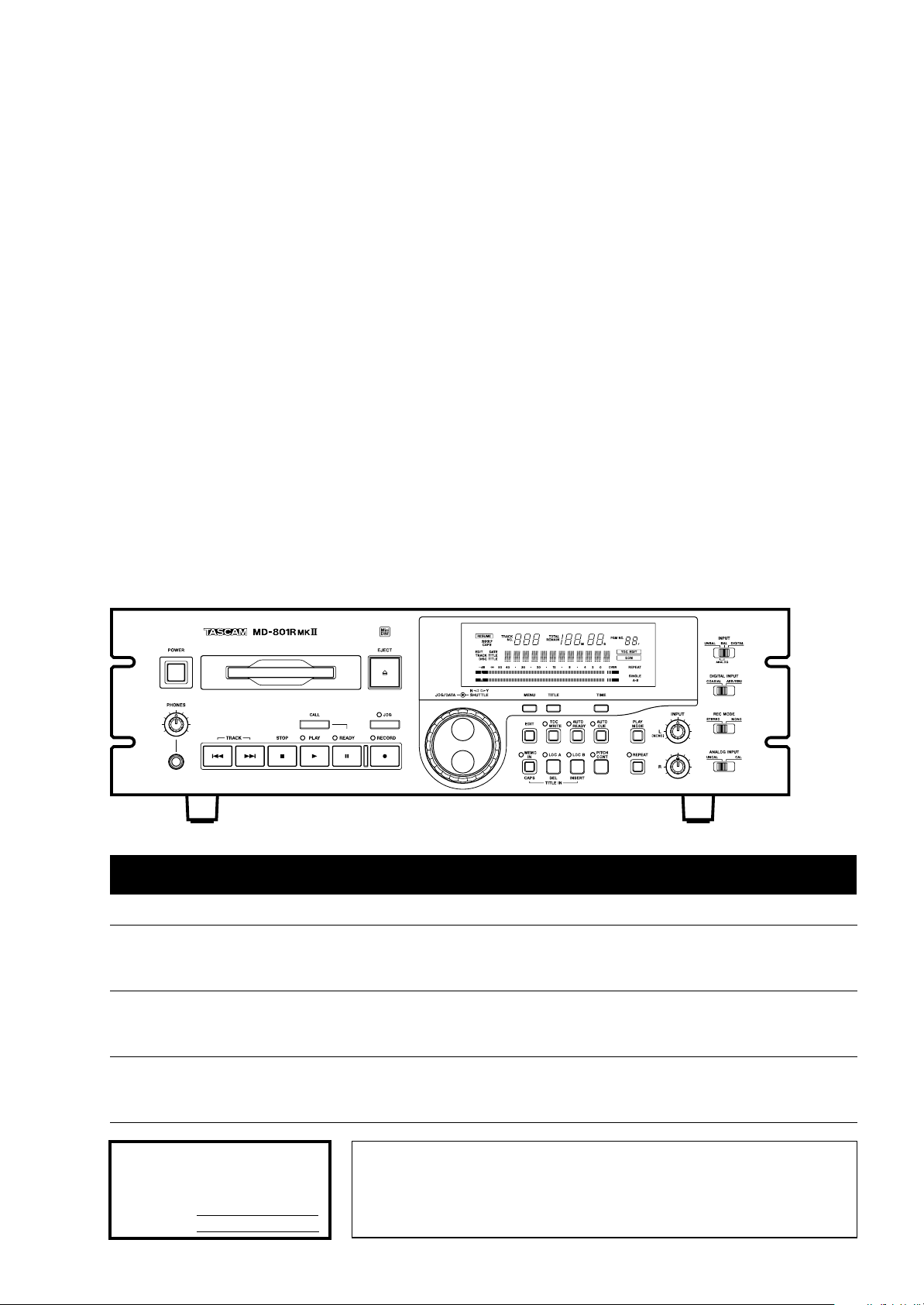
MD-801R@#/
MD-801P@#
MD Recorder/Player
OWNER’S MANUAL
Ü
The lightning flash with arrowhead symbol, within an equilateral triangle, is intended to alert
ÿ
Ÿ
This appliance has a serial number
located on the rear panel. Please record
the model number and serial number
and retain them for your records.
Model number
Serial number
the user to the presence of uninsulated “dangerous voltage” within the product’s enclosure
that may be of sufficient magnitude to constitute a risk of electric shock to persons..
The exclamation point within an equilateral triangle is intended to alert the user to the presence of important operating and maintenance (servicing) instructions in the literature
accompanying the appliance.
CAUTION: TO REDUCE THE RISK OF ELECTRIC SHOCK, DO NOT
REMOVE COVER (OR BACK). NO USER-SERVICEABLE PARTS
INSIDE. REFER SERVICING TO QUALIFIED SERVICE PERSONNEL.
WARNING: TO PREVENT FIRE OR SHOCK
HAZARD, DO NOT EXPOSE THIS
APPLIANCE TO RAIN OR MOISTURE.
Page 2

Important Safety Precautions
IMPORTANT (for U.K. Customers)
DO NOT cut off the mains plug from this equipment.
If the plug fitted is not suitable for the power points in your
home or the cable is too short to reach a power point, then
obtain an appropriate safety approved extension lead or
consult your dealer.
If nonetheless the mains plug is cut off, remove the
fuse and dispose of the plug immediately, to avoid
a possible shock hazard by inadvertent connection to the
mains supply.
If this product is not provided with a mains plug, or one has
to be fitted, then follow the instructions given below:
IMPORTANT:
accordance with the following code:
GREEN-AND-YELLOW :
BLUE :
BROWN :
WARNING:
The wires in this mains lead are coloured in
EARTH
NEUTRAL
LIVE
This apparatus must be earthed.
TO THE USER
This equipment has been tested and found to
comply with the limits for a Class A digital device,
pursuant to Part 15 of the FCC Rules. These
limits are designed to provide reasonable
protection against harmful interference when the
equipment is operated in a commercial
environment. This equipment generates, uses,
and can radiate radio frequency energy and, if
not installed and used in accordance with the
instruction manual, may cause harmful
interference to radio communications.
Operation of this equipment in a residental area
is likely to cause harmful interference in which
case the user will be required to correct the
interference at his own expense.
CAUTION
Changes or modifications to this equipment not
expressly approved by TEAC CORPORATION
for compliance could void the user’s authority to
operate this equipment.
As the colours of the wires in the mains lead of this apparatus
may not correspond with the coloured markings identifying
the terminals in your plug proceed as follows:
The wire which is coloured GREEN-and-YELLOW must be
connected to the terminal in the plug which is marked by the
letter E or by the safety earth symbol ç or coloured GREEN
or GREEN-and-YELLOW.
The wire which is coloured BLUE must be connected to the
terminal which is marked with the letter N or coloured
BLACK.
The wire which is coloured BROWN must be connected to
the terminal which is marked with the letter L or coloured
RED.
When replacing the fuse only a correctly rated approved type
should be used and be sure to re-fit the fuse cover.
IF IN DOUBT — CONSULT A COMPETENT
ELECTRICIAN.
For the consumers in Europe
WARNING
This is a Class A product. In a domestic environment, this
product may cause radio interference in which case the user
may be required to take adequate measures.
Pour les utilisateurs en Europe
AVERTISSEMENT
Il s’agit d’un produit de Classe A. Dans un environnement
domestique, cet appareil peut provoquer des interférences
radio, dans ce cas l’utilisateur peut être amené à prendre
des mesures appropriées.
Für Kunden in Europa
Warnung
Dies is eine Einrichtung, welche die Funk-Entstörung nach
Klasse A besitzt. Diese Einrichtung kann im Wohnbereich
Funkstörungen versursachen ; in diesem Fall kann vom
Betrieber verlang werden, angemessene Maßnahmen
durchzuführen und dafür aufzukommen.
US and foreign patents licensed from Dolby Laboratories Licensing Corporation.
2
–– TASCAM MD-801R/P Mk II
Page 3
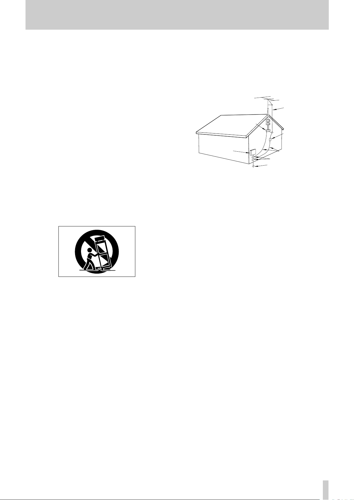
ANTENNA
LEAD IN
WIRE
ANTENNA
DISCHARGE UNIT
(NEC SECTION 810-20)
GROUNDING CONDUCTORS
(NEC SECTION 810-21)
GROUND CLAMPS
POWER SERVICE GROUNDING
ELECTRODE SYSTEM
(NEC ART 250. PART H)
NEC - NATIONAL ELECTRICAL CODE
ELECTRIC
SERVICE
EQUIPMENT
Example of Antenna Grounding as per
National Electrical Code, ANSI/NFPA 70
GROUND
CLAMP
IMPORTANT SAFETY INSTRUCTIONS
CAUTION:
Read all of these Instructions.
Save these Instructions for later use.
Follow all Warnings and Instructions marked on the audio
equipment.
1) Read Instructions — All the safety and operating instructions should
be read before the product is operated.
2) Retain Instructions — The safety and operating instructions should
be retained for future reference.
3) Heed Warnings — All warnings on the product and in the operating
instructions should be adhered to.
4) Follow Instructions — All operating and use instructions should be
followed.
5) Cleaning — Unplug this product from the wall outlet before cleaning.
Do not use liquid cleaners or aerosol cleaners. Use a damp cloth for cleaning.
6) Attachments — Do not use attachments not recommended by the
product manufacturer as they may cause hazards.
7) Water and Moisture — Do not use this product near water — for
example, near a bath tub, wash bowl, kitchen sink, or laundry tub; in a wet
basement; or near a swimming pool; and the like.
8) Accessories — Do not place this product on an unstable cart, stand,
tripod, bracket, or table. The product may fall, causing serious injury to a
child or adult, and serious damage to the product. Use only with a cart,
stand, tripod, bracket, or table recommended by the manufacturer, or sold
with the product. Any mounting of the product should follow the manufacturer’s instructions, and should use a mounting accessory recommended by
the manufacturer.
A product and cart combination should be moved with care. Quick stops,
excessive force, and uneven surfaces may cause the product and cart combination to overturn.
10) Ventilation — Slots and openings in the cabinet are provided for ven-
tilation and to ensure reliable operation of the product and to protect it
from overheating, and these openings must not be blocked or covered. The
openings should never be blocked by placing the product on a bed, sofa,
rug, or other similar surface. This product should not be placed in a built-in
installation such as a bookcase or rack unless proper ventilation is provided
or the manufacturer’s instructions have been adhered to.
11) Power Sources — This product should be operated only from the
type of power source indicated on the marking label. If you are not sure of
the type of power supply to your home, consult your product dealer or local
power company. For products intended to operate from battery power, or
other sources, refer to the operating instructions.
12) Grounding or Polarization — This product may be equipped with a
polarized alternating-current line plug (a plug having one blade wider than
the other). This plug will fit into the power outlet only one way. This is a
safety feature. If you are unable to insert the plug fully into the outlet, try
reversing the plug. If the plug should still fail to fit, contact your electrician
to replace your obsolete outlet. Do not defeat the safety purpose of the
polarized plug.
13) Power-Cord Protection — Power-supply cords should be routed so
that they are not likely to be walked on or pinched by items placed upon or
against them, paying particular attention to cords at plugs, convenience
receptacles, and the point where they exit from the product.
14) Outdoor Antenna Grounding — If an outside antenna or cable
system is connected to the product, be sure the antenna or cable system is
grounded so as to provide some protection against voltage surges and builtup static charges. Article 810 of the National Electrical Code, ANSI/NFPA
70, provides information with regard to proper grounding of the mast and
supporting structure, grounding of the lead-in wire to an antenna discharge
unit, size of grounding conductors, location of antenna-discharge unit, connection to grounding electrodes, and requirements for the grounding electrode.
"Note to CATV system installer:
This reminder is provided to call the CATV system installer’s attention to
…
…
…
9)
e)
a)
b)
c)
d)
Section 820-40 of the NEC which provides guidelines for proper grounding
and, in particular, specifies that the cable ground shall be connected to the
grounding system of the building, as close to the point of cable entry as
practical.
15) Lightning — For added protection for this product during a lightning
storm, or when it is left unattended and unused for long periods of time,
unplug it from the wall outlet and disconnect the antenna or cable system.
This will prevent damage to the product due to lightning and power-line
surges.
16) Power Lines — An outside antenna system should not be located in
the vicinity of overhead power lines or other electric light or power circuits,
or where it can fall into such power lines or circuits. When installing an
outside antenna system, extreme care should be taken to keep from touching such power lines or circuits as contact with them might be fatal.
17) Overloading — Do not overload wall outlets, extension cords, or
integral convenience receptacles as this can result in risk of fire or electric
shock.
18) Object and Liquid Entry — Never push objects of any kind into
this product through openings as they may touch dangerous voltage points
or short-out parts that could result in a fire or electric shock. Never spill
liquid of any kind on the product.
19) Servicing — Do not attempt to service this product yourself as open-
ing or removing covers may expose you to dangerous voltage or other
hazards. Refer all servicing to qualified service personnel.
20) Damage Requiring Service — Unplug this product from the wall
outlet and refer servicing to qualified service personnel under the following
conditions:
when the power-supply cord or plug is damaged.
if liquid has been spilled, or objects have fallen into the product.
if the product has been exposed to rain or water.
if the product does not operate normally by following the operating
instructions. Adjust only those controls that are covered by the operating
instructions as an improper adjustment of other controls may result in
damage and will often require extensive work by a qualified technician to
restore the product to its normal operation.
if the product has been dropped or damaged in any way.
f ) when the product exhibits a distinct change in performance – this
indicates a need for service.
21) Replacement Parts — When replacement parts are required, be
sure the service technician has used replacement parts specified by the
manufacturer or have the same characteristics as the original part.
Unauthorized substitutions may result in fire, electric shock, or other
hazards.
22) Safety Check — Upon completion of any service or repairs to this
product, ask the service technician to perform safety checks to determine
that the product is in proper operating condition.
23) Wall or Ceiling Mounting — The product should be mounted to a
wall or ceiling only as recommended by the manufacturer.
24) Heat — The product should be situated away from heat sources such
as radiators, heat registers, stoves, or other products (including amplifiers)
that produce heat.
TASCAM MD-801R/P Mk II ––
3
Page 4
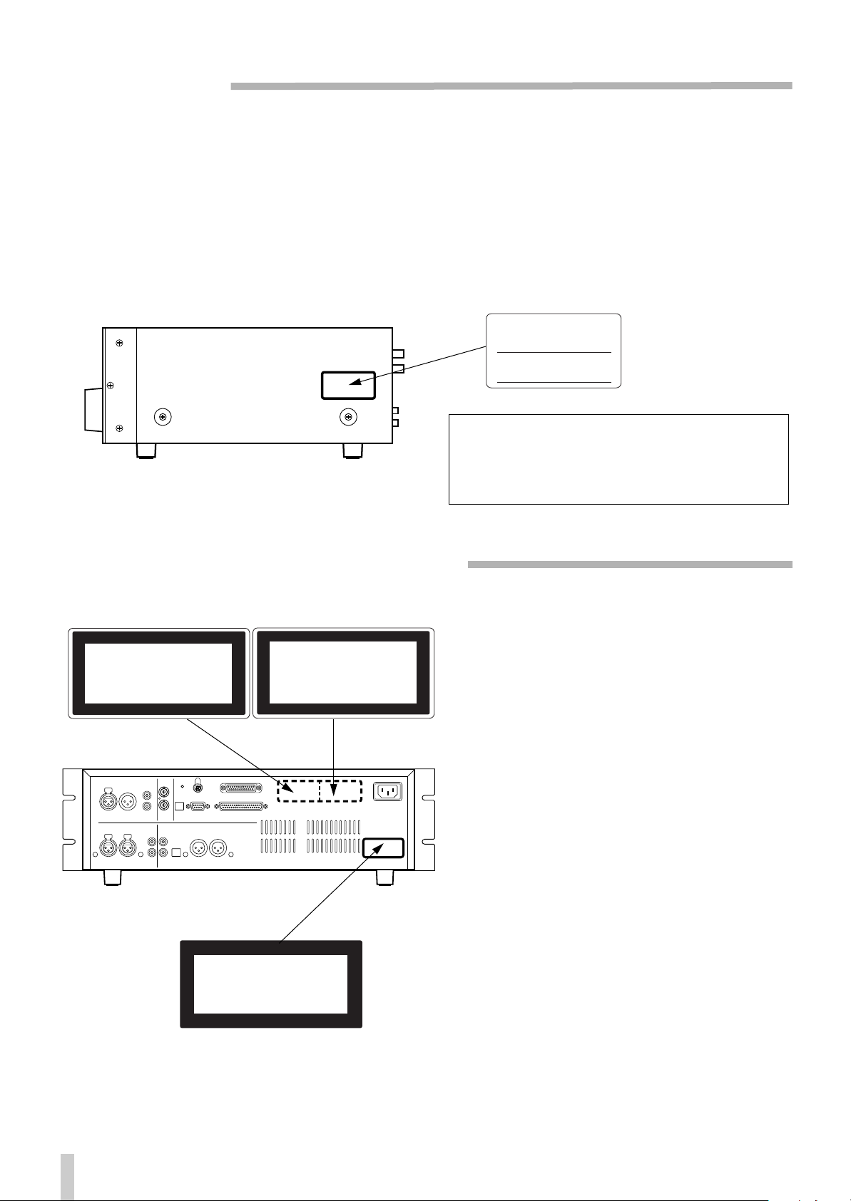
SAFETY INFORMATION
This product has been designed and manufactured according to FDA regulations "title 21, CFR, chapter 1, subchapter J, based on the Radiation
Control for Health and Safety Act of 1968", and is classified as class 1 laser product. There is not hazardous invisible laser radiation during operation because invisible laser radiation emitted inside of this product is completely confined in the protective housings.
The label required in this reguration is shown
… CAUTION
- DO NOT REMOVE THE PROTECTIVE HOUSING USING SCREWDRIVER.
- USE OF CONTROLS OR ADJUSTMENTS OR PERFORMANCE OF PROCEDURES OTHER THAN THOSE SPECIFIED HEREIN MAY RESULT IN HAZARDOUS RADIATION EXPOSURE.
- IF THIS PRODUCT DEVELOPS TROUBLE, MAKE A CONTACT WITH OUR SERVICEMAN, AND DO NOT USE THE PRODUCT IN A
TROUBLED STATE.
1.
For U.S.A.
1
CERTIFICATION
THIS PRODUCT COMPLES WITH DHHS
RULES 21 CFR SUBCHAPTER J APPLICABLE AT DATE OF MANUFACTURE
TEAC CORPORATION
3-7-3 NAKA-CHO, MUSASHINO-SHI, TOKYO, JAPAN
MANUFACTURED TIF
Optical pickup: Type : KMS-190A or KMS-190B
Manufacturer: SONY Corporation
Laser output: 0.25 mW Min. (Play),
5.0 mW Max. (Record)
Wavelength: 780 nm ±20 nm
…
CAUTION … ACHTUNG … OBSERVERA … ADVARSEL
2
ADVARSEL - USYNLIG LASERSTRÅLING VED ÅBNING, NÅR
SIKKERHEDSAFBRYDERE ER UDE AF FUNKTION.
UNDGÅ UDSÆTTELSE FOR STRÅLING.
VAROITUS! SUOJAKOTELOA EI SAA AVATA. LAITE SISÄLTÄÄ
LASERDIODIN, JOKA LÄHETTÄÄ (NÄKYMÄTÖNTÄ)
SILMILLE VAARALLISTA LASERSÄTEILYÄ.
ADVARSEL - USYNLIG LASERBESTRÅLING NÅR DENNE DELEN ER
ÅPEN OG SIKKERHETSSPERREN ER UTKOBLET.
UNNGÅ UTSETTELSE FOR STRÅLING.
CAUTION - INVISIBLE LASER RADIATION WHEN OPEN AND
INTERLOCKS DEFEATED. AVOID EXPOSURE TO BEAM.
VORSICHT! UNSICHTBARE LASERSTRAHLUNGTRITT AUS.
WENN DECKEL GEÖFFNET UND WENN
SICHERHEITSVERRIEGELUNG ÜBERBRÜCKT IST.
NICHT DEM STRAHL AUSSETZEN !
VARNING - OSYNLIG LASERSTRÅLNING NÄR DENNA DEL
ÄR ÖPPNAD OCH SPÄRR ÄR URKOPPLAD.
STRÄLEN ÄR FARLIG.
1
CLASS 1 LASER PRODUCT
LUOKAN 1 LASERLAITE
KLASS 1 LASERAPPARAT
1
THIS LABEL IS ATTACHED TO THE PLACE AS ILLUSTRATED TO
INFORM THAT THE APPARATUS CONTAINS A LASER COMPONENT.
DIESE AUFKLEBEMARKE IST AN DEM IN DER ABBILDUNG
1
GEZEIGTEN ORT ANGEBRACHT UM DARAUF HINZUWEISEN,
DASS IM INNERN DES GER
1 PÅSKRIFTEN SITTER PÅ APPARATEN SOM VISAS SOM UPPMAN-
ING OM ATT APPARATEN OMFATTAR EN INBYGGD LASERKOMPONENT.
1 DETTE MÆRKAT ER ANBRAGT SOM VIST I ILLUSTRATIONEN
FOR AT ADVARE BRUGEREN OM AT APPARATET INDEHOLDER
EN LASERKOMPONENT.
2 DETTE MÆRKAT ER SOM VIST PÅ ILLUSTRATIONEN ANBRAGT
PÅ INDERSIDEN AF TOPDÆKSLET FOR AT ADVARE BRUGEREN
OM AT YDERLIGERE FREMTRÆNGEN VIL VÆRE FORBUNDET
MED FARE FOR AT UDSÆTTE SIG FOR LASERSTRÅLING.
ADVARSEL — BETJENING AF ANDRE KONTROLLER OG REGULATORER ELLER BENYTTELES AF ANDRE FREMGANGSMÅDER
END BESKREVET HERI ER FORBUNDET MED FARE FOR UDSÆTTELSE FOR LASERSTRÅLING.
VARING: APPARATEN INNEHÅLLER LASER KOMPONENT MED
STRÅLNING ÖVERSTIGANDE KLASS 1.
"ADVARSEL: USYNLIG LASERSTRÅLING VED ÅBNING NAR
SIKKERHEDSAFBRYDERE ER UDE AF FUNKTION. UNDG
UDSAETTELSE FOR STRÅLING"
"VAROITUS! SUOJAKOTELOA EI SAA AVATA. LAITE SIS
LASERDIODIN. JOKA L
VAARALLISTA LASERS
ADVARSEL: USYNLIG LASERBESTRÅLING NÅR DENNE
DELEN ER ÅPEN OG SIKKERHETSSPERREN ER UTKOBLET
UNNGÅ UTSETTELSE FOR STRÅLING.
–– TASCAM MD-801R/P Mk II
4
Page 5

Table of Contents
1 - Introduction
1.1 About the MiniDisc format ................1-1
1.1.1 ATRAC compression.......................... 1-1
1.1.2 Buffer memory .................................... 1-1
1.1.3 Random access and U-TOC...............1-1
1.1.4 Track titling, etc. ................................. 1-2
1.2 Care of MD media...............................1-2
1.3 About the MD-801R/P Mk II................1-2
1.3.1 Unpacking the unit.............................. 1-3
1.3.2 Rack-mounting the unit......................1-3
1.3.3 Care of the unit.................................... 1-3
1.3.4 Backup memory.................................. 1-4
1.4 About this manual..............................1-4
2 - Front and rear panel features
2.1 Front panel..........................................2-1
[1] POWER switch........................................2-1
[2] Disc drive ................................................ 2-1
[3] EJECT key............................................... 2-1
[4] TRACK keys............................................ 2-1
[5] STOP key.................................................2-1
[6] PLAY key and indicator ......................... 2-1
[7] READY key and indicator ...................... 2-1
[8] RECORD key and indicator ................... 2-1
[9] PHONES jack and level control.............2-2
[10] CALL key............................................... 2-2
[11] JOG key and indicator ......................... 2-2
[12] JOG/DATA dial......................................2-2
[13] SHUTTLE wheel.................................... 2-2
[14] Display...................................................2-2
[15] MENU key.............................................. 2-2
[16] TITLE key............................................... 2-2
[17] TIME key................................................ 2-2
[18] EDIT key ................................................ 2-3
[19] TOC WRITE key and indicator.............2-4
[20] AUTO READY key and indicator......... 2-4
[21] AUTO CUE key and indicator.............. 2-4
[22] PLAY MODE key................................... 2-4
[23] MEMO IN/CAPS key and indicator...... 2-4
[24] LOC A/DEL & LOC B/INSERT keys
and indicators ........................................... 2-4
[25] PITCH CONT key and indicator........... 2-4
[26] REPEAT key and indicator .................. 2-4
[27] INPUT LEVEL controls......................... 2-5
[28] INPUT selection switch........................ 2-5
[29] DIGITAL INPUT switch......................... 2-5
[30] REC MODE switch................................ 2-5
[31] ANALOG INPUT switch........................ 2-5
2.2 Display ................................................2-5
(1) RESUME indicator................................. 2-5
(2)
(3) CAPS indicator ...................................... 2-5
(4) EDIT indicator........................................ 2-5
(5) DATE indicator....................................... 2-5
(6) TRACK TITLE indicator......................... 2-5
(7) DISC TITLE indicator............................. 2-6
(8) TRACK NO. display and indicator........ 2-6
(9) Time display and indicators................. 2-6
indicator.................................. 2-5
(10) PGM NO................................................. 2-6
(11) Dot-matrix alphanumeric display ....... 2-6
(12) TOC EDIT indicator.............................. 2-6
(13) EOM....................................................... 2-6
(14) Peak level meters................................. 2-6
(15) REPEAT indicator ................................ 2-6
(16) SINGLE indicator.................................. 2-6
(17) A–B indicator........................................ 2-6
2.3 Rear panel.......................................... 2-6
[32] DIGITAL INPUT (AES/EBU)...................2-6
[33] DIGITAL OUTPUT (AES/EBU)...............2-6
[34] DIGITAL INPUT (COAXIAL) ..................2-7
[35] DIGITAL OUTPUT (COAXIAL) ..............2-7
[36] ANALOG INPUTS and trimmers
(BALANCED)..............................................2-7
[37] ANALOG INPUTS (UNBALANCED)......2-7
[38] ANALOG OUTPUTS (MONITOR)..........2-7
[39] Analog output function DIP switch
bank............................................................2-7
[40] ANALOG OUTPUTS (LINE) and
trimmers.....................................................2-7
[41] WORD SYNC IN.....................................2-8
[42] WORD SYNC THRU...............................2-8
[43] MODE SET DIP switch bank.................2-8
[44] KEYBOARD connector.........................2-8
[45] REMOTE (SERIAL) connector..............2-8
[46] REMOTE CONTROL connector............2-8
[47] REMOTE (PARALLEL) connector........2-8
[48] ~ IN (power in connector).....................2-8
3 - Menu items
3.1 Basic principles of menu operations3-1
3.2 Pitch control....................................... 3-1
3.3 Auto cue............................................. 3-1
3.4 Frame display .................................... 3-1
3.5 Jog loop length.................................. 3-1
3.6 Resume setting.................................. 3-2
3.7 EOM disc............................................ 3-2
3.8 EOM track........................................... 3-2
3.9 Timer-controlled playback................ 3-2
3.10 Incremental play.............................. 3-3
3.11 Serial communications................... 3-3
3.11.1 Baud rate............................................3-3
3.11.2 Word length........................................3-3
3.11.3 Parity...................................................3-3
3.11.4 Stop bits.............................................3-3
3.12 Check items ..................................... 3-3
3.12.1 Spindle motor time............................3-4
3.12.2 Laser pickup time..............................3-4
3.12.3 System software version..................3-4
3.13 Auto track numbering level............ 3-4
3.14 Copy ID............................................. 3-4
3.15 Post-script recording...................... 3-4
4 - Basic operations
4.1 Inserting and ejecting discs............. 4-1
4.2 Playback of discs .............................. 4-1
TASCAM MD-801R/P Mk II
–i
Page 6

Table of Contents
4.2.1 Playing back a whole disc.................. 4-1
4.2.2 Playback outputs ................................ 4-1
4.2.3 Monaural playback.............................. 4-1
4.2.4 Playing back a single track................ 4-2
4.2.5 Entering the A and B location points 4-2
4.2.6 Playback between two location
points ......................................................... 4-2
4.2.7 The CALL function..............................4-2
4.2.8 Relative time display .......................... 4-2
4.2.9 Repeat playback.................................. 4-3
4.2.10 Track search operations .................. 4-3
4.2.11 Cueing the next track automatically 4-3
4.2.12 Cueing to the first audio position in
a track ........................................................ 4-3
4.2.13 Varispeed mode ................................ 4-3
4.2.14 Jog mode........................................... 4-3
4.2.15 Shuttle mode ..................................... 4-4
4.2.16 Displaying track titles during
playback..................................................... 4-4
4.2.17 Displaying the recording date ......... 4-4
4.2.18 Setting the time and date ................. 4-4
4.3 Recording operations........................ 4-4
4.3.1 General notes on recording using the
MD format .................................................. 4-5
4.3.2 Rebuilding the TOC ............................ 4-5
4.3.3 Basic recording...................................4-5
4.3.4 Track number incrementing............... 4-6
4.3.5 “Post-Script” recording...................... 4-6
4.3.6 Replace recording............................... 4-6
4.3.7 Sound synchro recording .................. 4-7
4.3.8 Digital recording ................................. 4-7
4.3.9 Analog recording ................................ 4-8
4.3.10 Track title copying together with
audio .......................................................... 4-8
5 - Editing operations
5.1 Basic editing operations................... 5-1
5.1.1 Cancelling an edit operation..............5-1
5.1.2 Editing without saving the edits to
disc.............................................................5-1
5.2 Dividing tracks................................... 5-1
5.3 Erasing a track................................... 5-2
5.4 Combining tracks ..............................5-2
5.5 Moving tracks..................................... 5-3
5.6 A and B point erase operations........ 5-3
5.6.1 Normal A-B erase.................................5-4
5.6.2 Erasing to the end of a track ..............5-4
5.6.3 Erasing from the start of a track ........5-4
5.6.4 Erasing more than one track at a
time .............................................................5-4
5.6.5 Retaining a track title for use by the
second track after a division....................5-5
5.7 Moving an A-B point..........................5-5
5.8 Restoring erased material.................5-6
5.9 Changing track attributes..................5-6
5.10 Erasing a complete disc..................5-7
5.11 Track and disc title entry.................5-7
5.11.1 Deleting characters ...........................5-8
5.11.2 Inserting characters ..........................5-8
5.11.3 Changing characters.........................5-8
5.11.4 Editing existing titles.........................5-8
5.11.5 Viewing titles......................................5-8
5.11.6 Copying disc and track titles............5-9
6 - Use of a keyboard with the MD-801
6.1 General transport operations............6-1
6.2 Edit operations, etc............................6-1
6.2.1 Entering programmed playback.........6-1
6.2.2 Checking and editing a programmed
sequence....................................................6-2
6.2.3 Time-based location............................6-2
6.3 Flash start...........................................6-2
6.4 Direct track entry................................6-3
6.5 Track and disc title editing with the
keyboard ................................................6-3
7 - Remote control of the MD-801
7.1 REMOTE (PARALLEL) connector.....7-1
7.1.1 Tally indicators ....................................7-1
7.1.2 Fader start............................................7-2
7.1.3 Sequential playback and recording...7-2
8 - Specifications, etc.
8.1 Error messages and troubleshooting
guide.......................................................8-1
8.2 Specifications.....................................8-2
8.2.1 General MiniDisc .................................8-2
8.2.2 Analog I/O.............................................8-3
8.2.3 Digital I/O..............................................8-3
8.2.4 Other connections...............................8-3
8.2.5 General and electrical .........................8-3
8.3 Dimensional drawing.........................8-4
TASCAM MD-801R/P Mk II
–ii
Page 7

1 - Introduction
This manual covers the two models of the MD-801
Mk II product line: the MD-801R Mk II, which is
capable of recording and playing back on MiniDisc
media, and the MD-801P Mk II, which is for playback only of such media. Apart from the recording
and associated facilities provided on the MD-801R,
the functionality and specifications of the two units
are identical. For brevity, the unit will be referred to
as the “MD-801” in instances where there is no difference between the recording and playback models.
When a section of this manual describes a function
which is included as part of the MD-801R only, the
section will be marked as below:
3.12.2Laser pickup time
R
This indicates how long…
There are no features which are unique to the MD-
801P model.
1.1 About the MiniDisc format
Full explanations of the principles of magneto-optical recording may be found in a number of excellent
reference works, but briefly, during the recording
process, the disc is exposed to a strong laser beam
which heats the disc’s magnetic medium so that a
magnetic field can be applied to change the orientation of the magnetic particles. On cooling, this orientation is permanently fixed, unless the disc is
reheated and re-recorded.
The MD format therefore provides the convenience
and durability of an optical disc format with the reusabilty characteristics of tape.
1.1.1ATRAC compression
If a MiniDisc were to be recorded using exactly the
same techniques as a CD, the playback time would
be only 15 minutes of stereo playback.
However, using a technique known as ATRAC
(Adaptive TRansform Acoustic Coding), 74 minutes
of stereo audio at 44.1 kHz sampling frequency with
a 16-bit word length can be recorded on an MD.
This section provides some basic information regarding the MiniDisc format. If more detailed information is required, the reader is referred to one of the
many books on the subject. John Wilkinson,
of Digital Audio
an excellent reference source, particularly Chapter
12, which deals with the use of optical discs in audio
applications.
The MiniDisc format (MD) is a convenient form of
digital audio media, using optical playback, similar
to CDs.
The format of the MD is substantially smaller than
that of the CD, and the disc itself is housed in a cartridge with a shutter, similar to that of a 3.5” floppy
disc drive. The disc platter should never be removed
from this cartridge.
Pre-recorded MDs, which are manufactured in the
same way as commercial CDs, using a stamper process, are read using a laser beam to read the pits
stamped onto the disc.
Recordable MDs are also available, and the technology used for recording on a recordable MD is
magento-optical, allowing the disc to be re-used
many times. Shutters on both sides of the disc allow
access to the disc surface by the recorder’s laser and
magnetic head.
There is a third kind of MD, the hybrid, which contains pre-recorded pits at the center of the MD,
together with an area reserved for user recording.
2nd ed. Oxford: Focal Press, 1994 is
The Art
ATRAC uses two important pyscho-acoustic principles to reduce the size of the recorded data: the
greater sensitivity of the human ear to mid-range signals, relative to bass and treble signals, and the
“masking” effect, whereby quieter signals are hidden
by louder ones.
The ATRAC used in the MD-801R/P Mk II is a very
recent version of this encoding scheme (4.5), resulting in an almost inaudible loss of signal quality.
1.1.2Buffer memory
The ATRAC compression scheme has an additional
advantage, as a RAM buf fer must be provided for the
compressed data, before it is decoded and sent to the
D/A converters.
On the MD-801R/P Mk II, this buffer memory holds
about 10 seconds’ worth of data. The advantage is
that, unlike a CD player, the MD-801R/P Mk II is not
vulnerable to mechanical shocks and vibration, etc.,
which can cause a CD player playback pickup to
jump and cause audible skipping.
1.1.3Random access and U-TOC
The format of a recordable MD is much closer to that
of a computer disc than of conventional audio media.
The random access nature of the disc media allows a
logical “track” to be composed of sections of audio
data recorded at different points on the disc.
In the same way that a computer’s operating system
hides the details of the way that data is stored on the
TASCAM MD-801R/P Mk II
1–1
Page 8

1 - Care of MD media
disk from the user, and a file appears as one contiguous block of data (even though it may be spread ov er
many tracks and sectors of the disk), the MD player
allows separated audio data to appear as a continuous
audio track.
The MD-801 allows the creation and reading of a
User Table of Contents (U-TOC) on recordable
discs, which contain instructions to the player on the
logical arrangement of the tracks, where to find the
next audio segment to be played, etc. This is similar
to the directory tracks provided as part of a computer
disk operating system.
The random access facilities provided by the MD801 are significantly better than those to be found on
consumer MD decks. The effective start time can be
effectively zero, compared with hundreds of milliseconds on consumer units.
1.1.4Track titling, etc.
In common with other forms of digital audio media,
the MD medium allows other data to be recorded
alongside the audio data. In the MD medium, this is
used to provide alphanumeric disc and track titles,
which are shown on the display of the player.
In the case of the MD-801R/P Mk II, this information
may be conveniently entered through a standard
computer keyboard (PS/2 compatible), or through the
controls of the main unit.
In addition, a realtime clock allows date- and timestamping of tracks recorded on the unit or created or
edited through TOC editing functions.
These times will be displayed when the disc is
replayed on any one of the MD-801 series.
1.2 Care of MD media
The MD medium has been designed to be robust, and
the integration of the disc into a cartridge protects the
recorded surface from the worst effects of dust, fingerprints, and scratches.
Even so, there are some commonsense precautions
that you should take when storing and handling
MiniDiscs.
• Do not open the shutter and touch the surface of the
disc.
• Do not keep MiniDiscs in excessively dusty locations, in direct sunlight, in areas subject to high
temperatures, or high levels of humidity.
• If the cartridge becomes dirty, clean it with a dry,
soft cloth. Do not use any solvents or other liquids.
1.3 About the MD-801R/P Mk II
The MD-801R/P Mk II, based on the TASCAM MD801 series of MD recorder/players, and designed to
meet the requirements of audio professionals,
includes the following features:
• Full editing functions to divide, erase and combine
tracks, etc.
• Auto cue function, allowing the playback point to
be automatically cued to the first frame of a track,
using a selectable sensitivity level
• Auto ready function, allowing the playback point
to be “parked” in the play ready mode at the start of
each track
• A resume function, which holds in backup memory
the point where playback stopped, or the power
was disconnected
• Incremental play mode, allowing cueing of the
playback point to the start of the next track, as
determined by a selectable audio threshold level,
when playback is stopped
• “Soft mute” eliminates clicks, etc. when pausing
and restarting playback
• Dual time display
• Three playback modes: normal (whole disc), track
play, and A-B play (between two defined points)
• 3-point autolocation facility
• Repeat (disc, track, A-B)
• Either stereo or monaural playback may be
selected
• Pitch change ±9.9% in 0.1% steps
• Shuttle operations up to 100 x normal speed, and
jog to single-frame accuracy
• Digital outputs in COAXIAL (SPDIF) and AES/
EBU
• Word clock synchronization for inclusion of the
MD-801 in an all-digital audio setup
• Two sets of analog outputs: –10 dBV unbalanced
MONITOR
(XLR-type). The
for precise signal matching with other equipment
• Output selectable (using remote controllers) from
either
• High-quality DA convertor for optimum analog
audio quality
• Level 4.5 ATRAC system
• PS/2-compatible computer keyboard connector
allows titling and other remote control operations
(RCA) and +4 dBu balanced
LINE
outputs may be trimmed
MONITOR
or
LINE
LINE
TASCAM MD-801R/P Mk II
1–2
Page 9
1 - About the MD-801R/P Mk II
to be conveniently carried out using a standard k e yboard
• Remote control possible from dedicated TASCAM
remote control units (RC-801, RC-FS10/20, and
RC-8), or through industry-standard parallel or
serial interfaces
• T ally signals sent to controlling de vice at the end of
each track played back
• Optional RAM buffer expansion module (B U-801)
allows flash start of track playback
In addition, the MD801R Mk II provides the follow-
R
ing features:
• 20-bit A/D converter for increased audio quality
when recording
• Selectable Copy ID modes, including the SCMS
standard
• Integral sampling frequency converter, allowing
digital recording from material recorded at frequencies other than 44.1 kHz (48 kHz and 32 kHz)
• Digital inputs in both SPDIF and AES/EBU
formats
• The ability to record in monaural mode, doubling
the recording time available on a disc.
• Analog inputs in both +4 dBu balanced (XLRtype) and –10 dBV unbalanced (RCA) formats.
The balanced inputs may be trimmed to match
input signal levels
• Replace recording function, allowing recording to
be carried out in the middle of a track, while retaining the track title
• Sound sync function to allow the unit to start
recording automatically when a selectable audio
threshold level is exceeded
• Title dubbing from another MD-801 unit (requires
optional connecting cable PW-1XMD)
• Realtime clock for date- and timestamping
recorded material
1.3.1Unpacking the unit
When you unpack the unit, as well as the unit itself
and this manual, you should find:
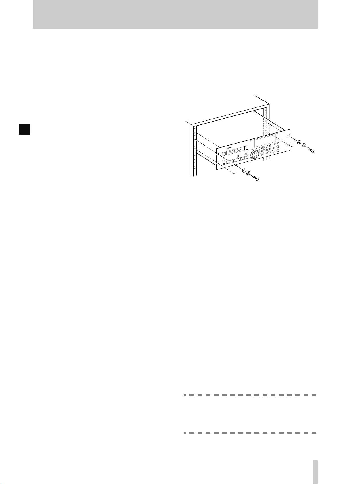
1.3.2Rack-mounting the unit
The MD-801 is equipped with integral rack-mount
ears, and may be installed in any standard vertical
19” rack.
Remove the feet from the MD-801 using a Phillips
screwdriver before installing the unit.
In addition to the 3U of space required for the MD801 itself, we strongly suggest leaving at least 1U of
empty rack space above the MD-801 for ventilation
purposes.
1.3.3Care of the unit
The commonsense precautions that you should take
with any piece of precision electronic equipment also
apply to the MD-801. In particular:
• Do not subject the unit to severe shocks or vibration. Despite the buffer mechanism mentioned
above, there is a risk of data loss, particularly while
recording.
• Do not use the unit in very dusty or smoky en vironments. If the optical lens or the head becomes dirty
as the result of such use, use a commercially-available MD lens and head cleaner to clean the lens.
• The exterior of the unit may be cleaned with a soft
dry cloth, or a cloth barely dampened with a mild
detergent solution. Do not use any solvent, thinner
or alcohol-based cleaning agents to clean the unit.
The date and time clock (for timestamping of recordings and edits) is powered by a lithium battery. We
suggest that this battery is changed about every two
years.
• Power cord
• Rack-mount kit
• Warranty card
If any items are missing, contact your TASCAM
dealer.
NOTE
Do not attempt to change this battery by yourself. Get an authorized TASCAM service center to perform this operation for you.
TASCAM MD-801R/P Mk II
1–3
Page 10

1 - About this manual
1.3.4Backup memory
When the unit is powered down, the following settings are memorized.
• AUTO READY status (see
• AUTO CUE settings and status (see
• The last used PLAY mode (see
• The two LOC points (A and B) (see
• Pitch control settings and status (see
• REPEAT status (see 4.2.9, "Repeat playback")
• Menu settings (see 3, "Menu items")
• If the resume function is turned on, the resume
point is memorized
[20]
)
[22]
[21]
)
[24]
[25]
1.4 About this manual
This manual has been organized so that you should
be able to find the section you need relatively
quickly. We suggest that you familiarize yourself
with at least the Table of Contents, so that you know
where to look if you need information on a particular
aspect of the unit’s operation.
An index is also provided, which should assist you in
locating the desired section.
As mentioned earlier, when a section of this manual
describes a function which is included as part of the
MD-801R only, the section will be marked as below:
3.12.2Laser pickup time
R
This indicates how long…
There are no features which are unique to the MD-
801P model only.
When characters are shown on the unit’s dot-matrix
display, the following typeface is used:
. Alternatively, the alphanumeric display itself
Mon
may be shown:
)
If a “preset” word or phrase is shown on the display,
)
)
this is shown as follows:
Track times, program numbers, as shown in 7-digit
numbers, are shown as
If a front panel control or rear panel connection is
mentioned, the following typeface is used (a little
larger than that used for preset display words):
WRITE
given in 2, "Front and rear panel features", may also
be given, e.g.
If a front panel control or rear panel connection of
another unit is specifically named, the folloiwng
typeface is used:
When an optional PS/2-compatible keyboard is connected to the MD-801, the keyboard keys are represented in the following typeface:
Press
F1
If two keys are to be pressed together (i.e. the firstnamed key is to be pressed and held down while the
second is pressed), this is represented as:
SHIFT
Press
function.
•d
TITLE ?
TRACK TITLE
034
, etc.
. The number of the control or connection, as
[5]
.
WORD IN
to go back by one track.
+ F1 to enter the erase track editing
.
Input
.
TOC
TASCAM MD-801R/P Mk II
1–4
Page 11
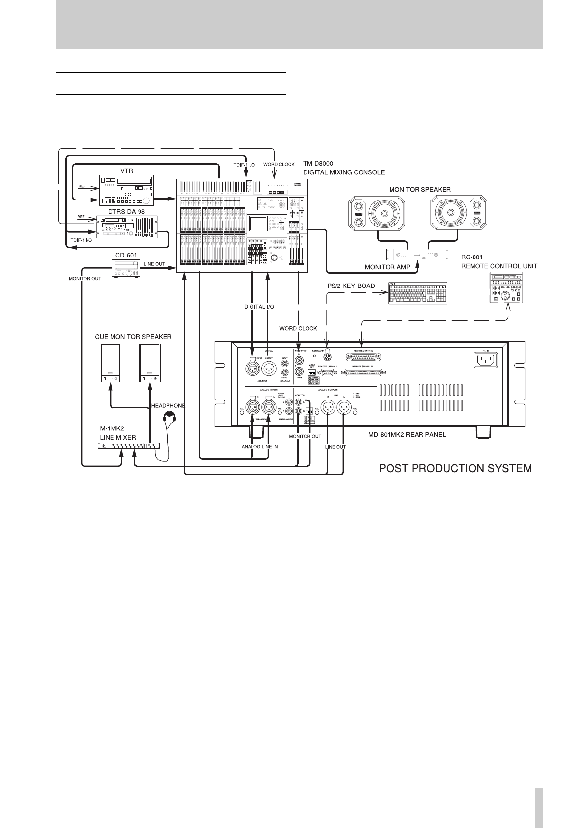
1.5 Hookup Examplel
1 - Hookup Examplel
TASCAM MD-801R/P Mk II
1–5
Page 12

2 - Front and rear panel features
TASCAM MD-801R/P Mk II
2–1
Page 13

2 - Front and rear panel features
This section, as well as giving a description of the
controls and features of the MD-801, also provides
many descriptions of basic operations.
The section on the rear panel also contains advice on
setting up and connecting the MD-801 as part of an
audio system.
2.1 Front panel
The following provides details of the basic functions
associated with the front panel controls of the unit. If
further information on the use of a particular control
is provided elsewhere in the manual, this is indicated.
[1] POWER switch
Press once to turn on the unit, and again to turn the
unit off.
NOTE
You should not turn the unit off while the UTOC (1.1.3, "Random access and U-TOC") is
being written. If power is disconnected from
the unit the U-TOC is being written, the disc
data will be corrupted, and the disc may
become unreadable.
Always remember to press the
key
[19]
before turning off power to the unit, in
order to save your edits to disc.
[2] Disc drive
Insert MiniDiscs into this slot, label uppermost, and
with the arrow pointing into the drive.
Use the
EJECT
key
[3]
to eject discs.
[3] EJECT key
Press this key to eject discs from the drive.
NOTE
If you press the
WRITE
indicator
there are edits that have been made, but not
yet saved to disc as part of the U-TOC, the
display will show
press the
disc, but all edits made since the last U-TOC
writing operation will be lost. If you want to
save the edits to disc, press the
key.
EJECT
EJECT
[19]
key when the
is lit, indicating that
TOC Edited!
key again, y ou can eject the
TOC WRITE
TOC
. If you
TOC WRITE
[4] TRACK keys
These keys are used to move the playback position
backwards or forwards a track at a time. Their use is
detailed in 4.2, "Playback of discs".
[5] STOP key
This key stops playback or recording (MD-801R
only). It is also used to cancel other operations.
[6] PLAY key and indicator
Used to start playback or recording (MD-801R only).
When the operation is taking place, the key’s indicator lights.
[7] READY key and indicator
Used to put the unit into play ready or record ready
(MD-801R only) mode. The indicator lights when
the unit is ready.
To start the operation, press the
If recording is taking place while the
R
pressed, the unit goes into record ready mode. The
current track number is incremented by one, to show
that the next recording will start a new track, if Postscript recording is turned on (see 3.15, "Post-script
recording").
To cancel a ready operation, press the
[8] RECORD key and indicator
R
If the unit is stopped, pressing the
will enter “input monitor” mode (the
indicator lights) and
the display. This is valid whether or not a disc is
loaded in the drive.
In input monitor mode, the signals received at the
appropriate connectors, as selected with the input
switches (
puts for monitoring as well as to the
[9]
, and the unit’s meters are used to display the signal levels. If the selected digital signal is not available, the
displayed.
The input level of the signals input at the analog
jacks may be adjusted using the
controls
If the
the
ready mode (a disc must be in the drive). Both the
RECORD
[28], [29]
D-IN UNLOCK!
[27]
.
RECORD
READY
key is pressed, the unit enters record
and
Input Mon
and
[31]
key is pressed and held down, and
READY
indicators will light.
PLAY
key
READY
STOP
RECORD
RECORD
appears on
) are routed to the out-
PHONES
message is
INPUT LEVEL
[6]
key
key
.
key is
[5]
jack
.
TASCAM MD-801R/P Mk II
2–2
Page 14

2 - Front panel
To start recording, press the
recording, press the
key has been pressed, the words
on the display, which will also show
Writing
To cancel record ready mode, press the
[5]
.
STOP
as the U-TOC is written to disc.
PLAY
key
key
[6]
[5]
. After the
TOC EDIT
UTOC
STOP
will flash
[9] PHONES jack and level control
Connect a pair of standard stereo headphones to this
1/4” jack. Adjust the level with the
The maximum output power is 50 mW per channel,
and the impedance is 32 Ω.
LEVEL
[10]CALL key
This key allows you to return to the point where the
READY
in play ready mode. The unit will return to this point,
and enter play ready mode (
cators lit). See also 4.2.7, "The CALL function".
The MD-801R also automatically sets the call point
R
at the point where recording last started. This enables
easy return to the point where the recording started,
using the
key
CALL
[7]
was last pressed while the unit was
READY
key, in order to check a take, etc.
and
PLAY
. To stop
STOP
key
control.
indi-
continuous.
The further the shuttle wheel is turned from the cen-
ter position, the faster the shuttle playback speed.
When the unit is in menu mode, this wheel is used in
the MD-801’s menu system. Turning it clockwise
generally confirms an action, and turning it counterclockwise acts as an “escape” action. It is also used
as a cursor control in titling operations.
[14]Display
See 2.2, "Display" below for details of the different
components that make up the display.
[15]MENU key
The
MENU
menus that allow the setting of different parameters
affecting the operation of the MD-801. See 3, "Menu
items" for full details of the menus and the different
options available in them.
key is used to cycle through the dif ferent
[16]TITLE key
The
TITLE
titles. It is also used to display the date and time
when the
key is used to show both disc and track
MEMO IN/CAPS
key indicator
[23]
is lit.
It may also be used to locate to the point which has
been located with the
JOG
dial
[12]
.
[11]JOG key and indicator
Use this key for precise positioning of the playback
point, in combination with the
When the jog mode is active, the
above this key is lit.
JOG/DATA
JOG
indicator
dial
[12]
[12]JOG/DATA dial
When the
tions as a jog dial, allowing precise positioning of the
playback point (confirmed with the
[7]
). See 4.2.14, "Jog mode" for full details of this
process.
When the
a data entry dial for entering values, titling characters, etc. Typically, turning this dial clockwise
increases the data value, and turning it counterclockwise decreases the value.
JOG
indicator
JOG
indicator is not lit, the dial is used as
[11]
is lit, this dial func-
READY
key
[13]SHUTTLE wheel
This wheel can be used for shuttle playback (forwards or backwards) when the unit is in play or play
ready mode. Since the MD-801 is a digital audio
device, the sound output during shuttle play is not
See 4.2.16, "Displaying track titles during playback"
and 4.2.17, "Displaying the recording date" for
details.
[17]TIME key
The
TIME
.
time display modes on the upper 7-segment numeric
indicators of the display during playback or in play
ready mode:
• (no indication)—the time elapsed from the start of
the current track
•
REMAIN
rent track
•
TOTAL
disc
•
TOTAL REMAIN
disc
It is also possible to make a time display which is relative to a “zero point” (see the section on 4.2.8, "Relative time display").
When the unit is in record or record ready mode, the
R
meanings change slightly, as shown below:
• (no indication)—the time elapsed from the start of
the track currently being recorded
key is used to cycle through the folloiwng
—the playback time remaining in the cur-
—the total elapsed time from the start of the
—the total time remaining on the
TASCAM MD-801R/P Mk II
2–3
Page 15

2 - Front panel
REMAIN
•
—the total time remaining on the disc for
further recording (the length of the blank portion of
the disc)
•
TOTAL
—the total elapsed time from the start of the
disc
•
TOTAL REMAIN
disc for further recording (the same as
If the
MEMO IN/CAPS
is in play or play ready mode, and the
—the total time remaining on the
indicator
REMAIN
[23]
is lit, the unit
TIME
)
key is
pressed, the lower (alphanumeric dot-matrix) part of
the display may be used to give timing information.
This is represented as follows:
•
—the time elapsed from the start of the cur-
elp
rent track
•
rem
—the playback time remaining in the current
track
•
tel
—the total elapsed time from the start of the
disc
•
•
—the total time remaining on the disc
tre
—the time relative to a user-settable “zero
rel
point” (see 4.2.8, "Relative time display")
to display the following:
•
aay bbm ccd
bb
is the month, and cc is the day of the date
—where aa is the year,
according to the MD-801’s internal clock.
•
eeh ffm ggs
—where ee is the hour (in
24-hour format), ff the minutes and gg the seconds of the time of day according to the MD-801’s
internal clock.
If the internal clock needs to be adjusted, follow the
procedure described in 4.2.18, "Setting the time and
date".
[18]EDIT key
The
EDIT
key is used to access various data and disc
editing modes, as detailed below.
When the
[12]
options as detailed below.
When an editing mode is shown, followed by a ques-
tion mark, turning the
wise will enter that editing mode.
EDIT
key is pressed, the
JOG/DATA
is used to cycle through the various editing
SHUTTLE
wheel
[13]
clock-
dial
When the unit is in record or record ready mode, and
R
the
MEMO IN/CAP
TIME
key is pressed, the lower (alphanumeric dot-
indicator
[23]
is lit, and the
matrix) part of the display may be used to give timing information. This is representated as follows:
elp
•
—the time elapsed from the start of the track
currently being recorded
•
—the total time remaining on the disc for
rem
further recording (the length of the blank portion of
the disc)
•
tel
—the total elapsed time from the start of the
disc
•
•
—the total time remaining on the disc for
tre
further recording (the same as
—the time relative to a user-settable “zero
rel
rem
)
point” (see 4.2.8, "Relative time display")
It is therefore possible to have two separate time indicators shown simultaneously. Note that if both the
upper and lower parts of the display are set to the
same time indication, there may be occasions where
the two values shown do not always match exactly.
To turn off the time display in the lower part of the
display, press the
TIME
key until the disc or track
title is shown, rather than the time display.
In the play and play ready, as well as the record and
record ready modes, the
TIME
key can also be used
To exit the editing mode, the
be turned counterclockwise, the
pressed once again, or the
SHUTTLE
EDIT
STOP
key
wheel can
key can be
[5]
can be
pressed.
The following is a list and brief description of the
editing functions available. Full details are given in
5, "Editing operations":
•
DIVIDE?—Divides a track into two tracks
•
ERASE TRK?—Erases a track
•
COMBINE?—Joins two tracks into one
•
MOVE?—Moves tracks in a sequence
•
ERASE A-B?—Erases data between the A
and B points
•
INSERT A-B?—Commits an insertion to
disc
RESTORE?—Restore an erased track or sec-
•
tion (can be regarded as an “undo” function)
•
TRK ATTR?—Sets track attributes
•
ERASE DISC?—Erases the contents of the
disc
•
TITLE?—Enters a track or disc title
NOTE
It is possible to perform editing operations on
pre-recorded (read-only) discs. However,
TASCAM MD-801R/P Mk II
2–4
Page 16

2 - Front panel
these edits cannot be committed to disc using
the
TOC WRITE
function (see below).
[19]TOC WRITE key and indicator
After an edit operation has been selected and performed from the
indicator will light, and the
display will be lit. This is a reminder that the disc
should not be ejected before the U-TOC has been
written to disc.
Press the
be written to disc, during which time the
indicator in the display will flash.
See the explanation of the
of how to eject a disc without writing the U-TOC, if
this is required.
TOC WRITE
EDIT
key
[18]
, the
TOC WRITE
TOC EDIT
key, and the editing data will
EJECT
indicator in the
key
[3]
TOC EDIT
for details
[20]AUTO READY key and indicator
Use this key to put the unit into auto ready mode (the
indicator will light). The auto ready mode provides
automatic “track at a time” playback.
•
SINGLE
back mode is selected
• (blank)/
disc, from the start to the end
•
A-B
been set (see
these points
Once a playback mode has been selected, the
REPEAT
of the disc being played back (track, disc or A-B
portion).
/
SINGLE MODE
CONTINUE
/
A-B MODE
[24]
), playback will loop between
key
[26]
can be used to repeat the portion
—Single-track play-
—Continuous play of a
—If the A and B points have
[23]MEMO IN/CAPS key and indicator
This key is used for a variety of functions: entering
memory location points, acting as a “caps lock” key
when entering disc and track titles, and as a display
mode selector (see
Its uses are described more fully in the various sections dealing with the functions that it controls.
[17]
), etc.
[24]LOC A/DEL & LOC B/INSERT keys
and indicators
When in auto ready mode, the unit will go into play
ready mode when the start of a track is reached in
playback. See 4.2.11, "Cueing the next track automatically" for full details.
[21]AUTO CUE key and indicator
Use this key to put the unit into auto cue mode (the
indicator will light). The auto cue mode allows the
elimination of “dead time” at the start of tracks,
allowing easy pre-cuing of commercials, jingles,
Foley effects, etc.
When the unit is in auto cue mode and stopped, and
the
READY
forward for the first audio frame above a given
threshold level, and cue itself to that location. It will
then enter play ready mode.
A similar process occurs when a track search operation has occurred.
See 4.2.12, "Cueing to the first audio position in a
track" for further details.
key
[7]
is pressed, the unit will search
[22]PLAY MODE key
Use this key to cycle between the different playback
modes. This key is enabled in the stop and the play
ready modes.
Both the display preset indicators and the alphanumeric part of the display are used to show the current
playback mode status, as follows:
These keys are used to set memory location points,
which are used for location, repeat play, editing purposes, etc. These points are retained until the disc is
ejected (including at power-of f). See 4.2.5, "Entering
the A and B location points" for details of how to set
these positions.
These keys may also be used for locating to the
points which have been set.
In title editing mode, the A and B keys are used to
delete and insert characters, respectively. See 5.11,
"Track and disc title entry".
[25]PITCH CONT key and indicator
Use this key to enter the pitch control mode (the indicator lights when this mode is active). When pitch
control is active, the speed (and pitch) of playback
can be altered by ±9.9%.
NOTE
Pitch control is not possible when the MD-801
is receiving its word clock from an external
source (see
The exact amount of pitch control is set through a
menu item (see 3.2, "Pitch control" for details).
[43]
).
[26]REPEAT key and indicator
Use this key to start repeat play of the selected playback portion of the disc (see
[22]
). When in repeat
TASCAM MD-801R/P Mk II
2–5
Page 17

2 - Display
mode, the
play . See 4.2.9, "Repeat playback" for further details
of this mode.
[27]INPUT LEVEL controls
R
These controls adjust the level of the signal at the
analog connectors selected using the
tion switch
the unbalanced inputs
INPUT
When these controls are at about the “12 o’clock”
position, they represent a nominal level for the unbalanced inputs (and for the balanced inputs if the trimmer potentiometers of the balanced inputs are still at
the factory positions).
If the
position, the
control the level of the monaural signal.
REPEAT
[28]
(either the balanced inputs
switch
REC MODE
[31]
L (MONO) INPUT
indicator will be shown on the dis-
INPUT
[37]
is set to
switch
) when the
UNCAL
[30]
ANALOG
.
is set to the
control is used to
NOTE
The level of signals received at the digital
inputs
[28]INPUT selection switch
R
Use this switch to choose between the unbalanced
analog inputs (
inputs (
[32]
and
UNBAL [37]
BAL [36]
[34]
cannot be adjusted.
), the balanced analog
) or digital input (
DIGITAL
selec-
[36]
or
MONO
).
neither boosted nor attenuated, and a nominal signal
will be received at the standard le vel of either +4 dBu
(balanced,
A signal at the nominal analog level (0 dB) will show
as a reading of –16 dB on the unit’s meters (put
another way , there is 16 dB of headroom available on
the MD-801 relative to the nominal 0dB point).
[36]
) or –10 dBV (unbalanced,
[37]
).
2.2 Display
The different indicators and parts of the display are
shown here. We refer to the parts of the display
which light and show preset messages as “preset
indicators” or simply “indicators”.
(1) RESUME indicator
Lights when the resume mode is enabled from a
menu (see 3.6, "Resume setting").
[29]DIGITAL INPUT switch
R
Use this switch to choose between the
digital input
[34]
when the
the
DIGITAL
[30]REC MODE switch
R
Use this switch to choose between monaural and stereo recording.
In monaural recording mode, the left and right signals are combined, and only the left
control
signals.
In monaural recording, twice the recording time is
available on a disc than when recording in stereo.
[31]ANALOG INPUT switch
R
When an analog input has been selected using the
INPUT
switch to bypass the
When this switch is in the
trols are bypassed, and have no effect. Signals are
[32]
and the
INPUT
position.
[27]
is used to control the level of the analog
selection switch
COAXIAL
selection switch
[28]
, you can use this
INPUT
level controls
CAL
position, these con-
AES/EBU
digital input
[28]
INPUT
is set to
level
[27]
.
(2)
Lights when the entry of Japanese katakana characters (
katakana characters) is enabled, and will light if the
TITLE key [16] is pressed when the MEMO IN/
CAPS indicator [23] is lit. Press the TITLE key once
more to turn this off, and return to the entry of alphanumeric characters.
indicator
is the word “katakana” written in
(3) CAPS indicator
Lights when capital (uppercase) letters are being
used for title entry and editing (see [23] ).
(4) EDIT indicator
Lights when the unit is in EDIT mode. See 5, "Editing operations" for details of editing operations.
(5) DATE indicator
Lights when the unit is displaying the date on which
a recording was made (the MD-801R records the
date automatically). See 4.2.18, "Setting the time and
date" for details of facility.
TASCAM MD-801R/P Mk II
2–6
Page 18

2 - Rear panel
(6) TRACK TITLE indicator
Lights when track titles are being entered or displayed. See 5.11, "Track and disc title entry" for
details.
(7) DISC TITLE indicator
Lights when the title of the disc is being entered or
displayed. See 5.11, "Track and disc title entry" for
details.
(8) TRACK NO. display and indicator
This 3-digit 7-segment display usually shows the current track. It may also be used to show a track number other than the current one, depending on the
mode.
When the incremental play mode is on (see 3.10,
"Incremental play"), this indicator will flash.
(9) Time display and indicators
Shows the elapsed or remaining time using a 7-digit
7-segment display (3 digits for minutes, 2 for seconds and optionally 2 for frames). See the explanation of the
time display modes.
TIME
key
[17]
for details of the different
R
OVER
The
Digital clipping is a harsh-sounding form of
distortion, unlike, say, analog tape saturation,
and should be avoided.
When connected to analog equipment, the nominal
analog level is referenced to a reading of –16 dB on
the meters (see
indicator indicates digital clipping.
[31]
NOTE
).
(15)REPEAT indicator
Lights when the unit is in repeat playback mode (see
[26]
).
(16)SINGLE indicator
Lights when a single track has been selected for playback (see
[22]
).
(17)A–B indicator
Lights when the A-B playback mode has been
selected (see
[22]
).
2.3 Rear panel
(10)PGM NO.
Lights in programmed play mode (see 6.2.1, "Entering programmed playback") and is used with the last
2 digits of the time display
(9)
.
(11)Dot-matrix alphanumeric display
These dot-matrix elements are used to display alphanumeric information: track and disc titles, time display, menu options, etc.
Note that the term “alphanumeric” is not strictly
accurate here, as these elements can also display
some punctuation as well as Japanese
katakana (2)
(12)TOC EDIT indicator
Lights in the U-TOC editing modes and after a disc
U-TOC has been edited (see
to disc.
[19]
) until it is written
(13)EOM
Lights briefly at the end of each track, or at the end of
the disc.
(14)Peak level meters
Display the signal level on playback or when recording (MD-801R only).
This section gives details of the connections which
should be made to and from the MD-801.
NOTES
When making or breaking connections
between the MD-801 and other units, make
sure the power is turned off to all units. This
will avoid possible damage to monitoring
equipment, etc. caused by transients.
The use of analog cables is not recom-
.
mended for digital audio use, and TASCAM
cannot guarantee reliable perf ormance if such
cables are used for digital audio connections.
[32]DIGITAL INPUT (AES/EBU)
R
This XLR-type connector accepts digital audio data
in AES3-1992 format.
It also accepts balanced data in the IEC 60958 (consumer) format (SPDIF).
The input sampling frequency can be 32 kHz,
44.1 kHz or 48 kHz. The MD-801’s internal sam-
pling frequency converter will convert them all to
44.1 kHz for recording.
TASCAM MD-801R/P Mk II
2–7
If switch 4 of the
is set off, the signals input here are echoed at the dig-
MODE SET
DIP switch bank
[43]
Page 19

2 - Rear panel
ital outputs
[33]
and
[35]
without passing through
the frequency converter.
[33]DIGITAL OUTPUT (AES/EBU)
This XLR-type connector outputs digital audio data
in AES3-1992 format.
The output sampling frequency will always be
44.1 kHz, ±9.9%, as determined by the pitch control
(see both 4.2.13, "Varispeed mode" and 3.2, "Pitch
control").
[34]DIGITAL INPUT (COAXIAL)
R
This RCA connector accepts digital audio data in
IEC 60958 (consumer) format (SPDIF).
The input sampling frequency can be 32 kHz,
44.1 kHz or 48 kHz. The MD-801’s internal sampling frequency converter will convert them all to
44.1 kHz for recording.
If switch 4 of the
MODE SET
DIP switch bank
is set off, the signals input here are echoed at the digital outputs
[33]
and
[35]
without passing through
the frequency converter.
[35]DIGITAL OUTPUT (COAXIAL)
This RCA connector outputs digital audio data in
IEC 60958 (consumer) format (SPDIF).
The output sampling frequency will always be
44.1 kHz, ±9.9%, as determined by the pitch control
(see both 4.2.13, "Varispeed mode" and 3.2, "Pitch
control").
[36]ANALOG INPUTS and trimmers
R
(BALANCED)
These XLR-type connectors accept balanced analog
signals at professional (+4 dBu) levels.
The wiring is, as marked on the rear panel:
1=ground, 2=hot (+), 3=cold (–).
The nominal impedance is 2.2 kΩ.
The trimmer potentiometers by each connector may
be turned counterclockwise or clockwise to cut or
boost respectively the level of the signal received at
the inputs. The maximum cut achievable (relative to
nominal) is –4 dB and the maximum boost is +7 dB.
As shipped, the trimmers are set to the standard
+4 dBu level.
[43]
[38]ANALOG OUTPUTS (MONITOR)
These RCA unbalanced connectors provide output
signals at the –10 dBV level.
The nominal impedance is 220 Ω.
[39]Analog output function DIP switch
bank
This bank of four DIP switches is used to control the
outputs from the
puts
[38]
and
They have the following meanings:
OFF
(up)
No
1
STEREO
2
SYNCHRONIZE
3
LINE MON OFF
4 Reserved—leave in the
The
PHONES
regardless of the settings made using these
switches.
MONITOR
[40]
.
ON
(down)
Allows the output mode from both
the
puts to be set to
STEREO
MONO
the
When set to
LINE
paralleled. When set to
INDIVIDUAL
from the
when the
itself, or the
optional RC-801 is pressed. To output signals from the
when this switch is set to
INDIVIDUAL
INDIVIDUAL
key on the optional RC-801, or
send a “play” command from a
remote controller connected to the
serial or parallel interface.
When
outputs output a signal depends on
the setting of switch 2 in this bank
(i.e. if switch 2 is on, the
MONITOR
when the MD-801’s
been pressed). When ON, monitoring is always on, regardless of from
LINE MON ON
where the play command originated.
OFF
NOTE
output
and
LINE
LINE
and the
PHONES
and
MONITOR
PLAY
OFF
position
[9]
is always active,
MONITOR
MONO
, as well as output from
jack.
SYNCHRONIZE
MONITOR
, signals are output
outputs only
key on the MD-801
MONITOR
LINE
, use the
, whether the
outputs are only active
analog out-
out-
or
, the
outputs are
key on the
outputs
ONLINE
MONITOR
PLAY
key has
[37]ANALOG INPUTS (UNBALANCED)
R
These RCA connectors accept unbalanced signals at
the –10 dBV level.
The nominal impedance is 8 kΩ.
[40]ANALOG OUTPUTS (LINE) and
trimmers
These XLR-type connectors output balanced analog
signals at professional (+4 dBu) levels.
TASCAM MD-801R/P Mk II
2–8
Page 20

2 - Rear panel
The wiring is, as marked on the rear panel:
1=ground, 2=hot (+), 3=cold (–).
The nominal impedance is 11 Ω.
The trimmer potentiometers by each connector may
be turned counterclockwise or clockwise to cut or
boost respectively the level of the signal sent from
these connectors. The maximum cut achiev able (relative to nominal) is –7 dB and the maximum boost is
+4 dB.
As shipped, the trimmers are set to the standard
+4 dBu level.
[41]WORD SYNC IN
This BNC connector accepts a 44.1 kHz word clock
(impedance 75 Ω) at 44.1 kHz (±6%).
[42]WORD SYNC THRU
This self-terminating BNC connector echoes the
word clock signal received at
[41]
.
[43]MODE SET DIP switch bank
This switch bank allows the setting of various local
parameters.
OFF
(up)
No
1
2
3
ON
(down)
Allows the selection of a Japanese
(106-key) keyboard (
) or an American-style (101-
KYBD
key) keyboard (
US KBD
JAPAN KBD
FAIL SAFE OFF
EXT CLK INTERNAL
connected to
When set
ational controls are enabled.
When set
on the front panel are enabled when
the MD-801 is playing as the result
of e command received from an
FAIL SAFE ON
external controller (RC-801, etc.).
When
received at
the unit uses its own internal
clocking.
When set to
the signal received at the
SYNC IN
EXT CLK EXTERNAL
OFF
ON
OFF
JAPAN
US KBD
[44]
, all front panel oper-
, only the
, any word clock signals
[41]
, the unit clocks to
ON
.
[41]
) to be
for titling, etc.
STOP
key
are not used, and
WORD
OFF
(up)
No
4
ON
(down)
When
at either
directly retransmitted.
When the switch is set to ON,
received digital signals are retransmitted directly from the digital outputs
D-IN THRU
D-IN NORMAL
autonumbering, etc. to take place
using multiple MD-801 units
“daisy-chained” together.
OFF
, digital signals received
[32]
[33]
and
or
[35]
[34]
are not
. This allows
[44]KEYBOARD connector
This connector is used to connect a PS/2-type computer keyboard which can be used for the direct
alphanumeric entry of titles, etc. as well as for controlling playback operations.
Depending on the setting of
switch 1
[43]
, either a US-type or a Japanese-type
MODE SET
bank DIP
keyboard can be used. See 6, "Use of a keyboard
with the MD-801" for details of keyboard-based
operations.
[45]REMOTE (SERIAL) connector
This RS-232 interface allows control by a computer
or by other serial controllers.
Consult your TASCAM dealer for details of this port
if you wish to use it.
[46]REMOTE CONTROL connector
Use this connector to attach either an optional RC801 remote contoller or an optional RC-FS10/20
remote controller. Consult your TASCAM dealer for
details of availability.
[47]REMOTE (PARALLEL) connector
Use this connector to attach an optional RC-8 remote
control unit or to control the deck from a controlling
device using parallel protocol.
[48]~ IN (power in connector)
Connect the supplied power cord to this inlet. Make
sure that your AC voltage matches the voltage
expected by the MD-801, as printed on the rear
panel.
TASCAM MD-801R/P Mk II
2–9
Page 21

The selections that can be made using the MD-801’s
menu system affect the operation of many other
functions. We suggest that you take the time to look
through this section and familiarize yourself with the
basic contents, so that you have an idea of some of
the options available to you.
3.1 Basic principles of menu
operations
The menu system is entered using the
1
key
[15]
. Pressing this key brings up a menu in
the display.
The
2
3
4
5
6
7
JOG/DATA
menu.
The
SHUTTLE
menu selected in step 2.
The
JOG/DATA
ters and enter values for the menu. Turn the dial
clockwise to increase values, and counterclockwise to decrease them.
“On” and “off” values are selected by turning
the
SHUTTLE
clockwise respectively (Y and N).
A few menus have “sub-menus” which are
selected using the
with the
When a menu item has been set in step 4, turn
the
the value and return to normal operation.
SHUTTLE
SHUTTLE
dial
[12]
is used to select a
wheel
wheel clock wise and counter-
wheel to the right (Y) to enter
[13]
is used to open the
dial is used to select parame-
JOG/DATA
wheel.
dial, and opened
MENU
3 - Menu items
3.3 Auto cue
A CUE LVL ?
The auto cue facility allows you to cue the playback
position automatically to the first frame where the
audio level goes above a trigger threshold (see
4.2.12, "Cueing to the first audio position in a
track"). This menu allows you to set the threshold.
The default setting is –54 dB.
After the menu has been opened with the
wheel, the display changes:
A CUE> -54dB
There are nine sensitivity levels available for use
with this function: –24 dB, –30 dB, –36 dB, –42 dB,
–48 dB, –54 dB, –60 dB, –66 dB and –72 dB.
This setting is also used with the Sound Synchro
R
function as the threshold above which recording
starts (or below which the unit drops into record
ready mode).
3.4 Frame display
FR DSPL SEL?
The frames part of the time display can be turned on
or off. There are either 86 or 87 MD frames per second. The default setting is on.
After the menu has been opened with the
wheel, the display changes:
FR DSPL>ON
SHUTTLE
SHUTTLE
To “escape” from menu mode without making a setting, turn the
press the
SHUTTLE
MENU
wheel to the left (N) or
key.
3.2 Pitch control
PITCH CONT ?
Pitch control can be set ±9.9%, in 0.1% steps. The
default setting is 0.0%.
After the menu has been opened with the
wheel, the display changes:
PITCH> 0.0%
See 4.2.13, "Varispeed mode" for details of pitch
control operations.
SHUTTLE
The only two options here are on and off.
3.5 Jog loop length
JOG LENGTH ?
As explained in 4.2.14, "Jog mode", when locating a
point using the
ing at the provisional jog point.
This menu allows you to set the length of the jog
loop. The default value is 16 frames (about 0.2
second).
After the menu has been opened with the
wheel, the display changes:
JOG
dial, playback is looped, start-
JOG LG> 16f
TASCAM MD-801R/P Mk II
SHUTTLE
3–1
Page 22

3 - Resume setting
The minimum length for the jog loop is 12 frames,
and the maximum value is 32 frames. The v alue is set
in 1-frame steps.
3.6 Resume setting
RESUME SEL ?
When the resume setting is turned on, playback
restarts from the point at which it was stopped (or the
point at which playback was taking place when the
power was cut off). The default is off, which means
that when playback is stopped, it will start at the
beginning of the disc, unless a track number is
explicitly specified.
This function, when on, changes the function of the
STOP
the
enters play ready mode. If the
once again, the MD-801 enters stop mode.
key
[5]
. When the resume function is on, and
STOP
key is pressed in play mode, the MD-801
STOP
key is pressed
R
NOTE
The EOM tally signal is always transmitted
when the U-TOC is updated as the result of a
recording operation having been completed,
unless this setting is set to off. It is also transmitted when recording is halted temporarily.
3.8 EOM track
EOM TRACK ?
The EOM track is similar to the EOM disc function,
as described above. The EOM tally signal is transmitted before the end of a track playback, and this
menu allows the time before the end to be set, or the
disabling of this function (default off).
When this message is transmitted, the
flashes in the display.
EOM
indicator
After the menu has been opened with the
SHUTTLE
wheel, the display changes:
RESUME> OFF
The options available are on and off.
3.7 EOM disc
EOM DISC ?
This menu item affects the output of the MD-801 to a
device attached to the parallel port (see 7.1,
"REMOTE (PARALLEL) connector". When set on,
an “EOM DISC” tally signal is transmitted from the
parallel port when the end of the disc is reached in
playback (or recording, in the case of the MD-801R).
When this message is transmitted, the
flashes in the display.
In this menu, it is possible to select how many seconds before the end of the disc this message is to be
sent, or to turn the message off completely. The
default setting is off.
After the menu has been opened with the
wheel, the display changes:
EOM DISC>OFF
The time may be set from 1 to 99 seconds, in 1 second steps, or set to off.
EOM
indicator
SHUTTLE
After the menu has been opened with the
SHUTTLE
wheel, the display changes:
EOM TRK> OFF
The time may be set from 1 to 99 seconds, in 1 second steps, or set to off.
3.9 Timer-controlled playback
TIMER PLAY ?
When this function is enabled, if a disc is in the unit,
and the unit is powered up (e.g. from a timer-based
switching unit), the TOC is read, and playback starts.
The default setting is off.
If the resume function is switched on (3.6, "Resume
setting") playback will start from the point at which
playback was last stopped, or at the playback point at
which the power was last cut off.
If the resume function is off, playback will start from
the beginning of the disc.
After the menu has been opened with the
wheel, the display changes:
TMR PLY>OFF
The options available are on and off.
SHUTTLE
TASCAM MD-801R/P Mk II
3–2
Page 23

3.10Incremental play
3 - Incremental play
When this sub-menu is opened, the baud rate can be
selected and set. The default value is 9600.
INCR PL SEL?
This function allows auto-cueing of the playback
point to the start of the next track when the
key
[5]
is pressed, or a fader stop command is
STOP
received (on pin 8 of the parallel remote control port
[47]
).
When this mode is enabled, pressing the
[6]
of the MD-801, or on an optional RC-801 or RC-
8 remote control unit (or the
MONITOR
PLAY
key of
key
either of these units), or a PS/2-type keyboard connected to the MD-801 will cue playback to the start
of the track following the current track, and start
playback from there.
NOTES
While this function is enabled, the
TRACK NO.
indicator flashes, as a reminder that the function is enabled.
The Auto Ready function (see 4.2.11, "Cueing
the next track automatically"), together with
the associated commands received at the
serial remote control port) is disabled when
this function is enabled.
BAUD> 9600
When a sub-menu value has been set with the
SHUTTLE
wheel, the unit returns to the normal set-
ting.
3.11.2Word length
The next sub-menu allows the setting of the word
length in serial communications:
LENGTH SEL ?
When this sub-menu has been opened, the word
length can be set to 7 or 8 bits. The default is 8 bits.
LENGTH>8bits
3.11.3Parity
The next sub-menu allows the setting of the parity to
be used in serial communications:
PARITY SEL ?
When this sub-menu has been opened, the parity can
be selected from off, odd or even parity. The default
is for off (no parity).
PARITY> OFF
3.11.4Stop bits
After the menu has been opened with the
SHUTTLE
wheel, the display changes:
INCR PL> OFF
Choose between on and off, with the default setting
being off.
3.11Serial communications
SERIAL SET ?
This menu allows the setting of parameters affecting
the serial (RS-232C) control port
contains sub-menus, allowing the different parameters to be accessed (
menus,
SHUTTLE
DATA
dial to show the sub-
wheel to open them).
3.11.1Baud rate
From the main menu, the first sub-menu allows the
setting of the communications speed (baud rate):
BAUD SEL ?
[45]
. This menu
The final sub-menu allows the setting of the number
of stop bits:
STOP BIT ?
When this sub-menu is opened, thje number of stop
bits can be set to 1 or 2. The default is 1.
STOP BIT> 1
3.12Check items
These are not settable menu items, but allow the
checking of various aspects of the MD-801 system.
When the following menu item appears, use the
SHUTTLE
dial to choose the different options.
Exit the menu system by turning the
wheel.
wheel to enter the menu, and the
CHECK ?
SHUTTLE
DATA
TASCAM MD-801R/P Mk II
3–3
Page 24

3 - Auto track numbering level
3.12.1Spindle motor time
S_TIME> 121
Use this to check how many hours the spindle motor
has been in operation.
3.12.2Laser pickup time
R
R_TIME> 43
This indicates how many hours the laser pickup has
been used for recording.
3.12.3System software version
SYS> 01.00
This allows you to check the current system software
version.
3.13Auto track numbering level
R
A_TRK LVL ?
This allows the setting of the threshold above which
a signal received at the
the analog connectors triggers the start of a new track
(see 4.3.4, "Track number incrementing"). This v alue
can be off, or one of nine values, as detailed below.
There should be a period of relative silence (i.e.
below the trigger level) of at least three seconds
between “tracks” in the source material for this function to operate.
AES/EBU
jack or either of
3.14Copy ID
R
COPY ID SEL?
When recording an MD on the MD-801, the copy ID
of the recorded MD can be set for different purposes.
The three settings available are:
• Copy Free—(
copies to be made from the digital recording made
on the MD-801
• First-generation copy only—(
only one digital copy to be made from the digital
recording produced on the MD-801
• Copy prohibit—(
digital copies can be made from the digital recording produced on the MD-801.
After the menu has been opened with the
wheel, the display changes:
The default setting is for free copying. The restrictions apply only to digital copies produced through
the
COAXIAL
recording is made when the disc is played back
through the
3.15Post-script recording
R
Free
COPY ID>Free
port. The copy bit is ignored if the
AES/EBU
PS REC ?
) allows unlimited digital
1 gen
Proh
) means that no further
connector.
SHUTTLE
) allows
NOTE
Bear in mind that some classical material,
spoken word, etc. may include such periods
of silence, and this may cause spurious track
divisions. Also, some analog material may be
noisy, and the noise may go above the track
division threshold. Adjust the threshold level
taking these factors into consideration.
After the menu has been opened with the
wheel, the display changes:
A_TRK> -54dB
The available settings are: –24 dB, –30 dB, –36 dB,
–42 dB, –48 dB, –54 dB, –60 dB, –66 dB, –72 dB
and off. The default value is –54 dB.
SHUTTLE
As explained in 4.3.5, "“Post-Script” recording",
recording can start either from the beginning of the
disc (when this function is turned off), or from the
beginning of the free space available, i.e. after the
last recorded track (when this function is turned on).
This function also controls the operation of the
replace recording function (see 4.3.6, "Replace
recording").
After the menu has been opened with the
wheel, the display changes:
PS REC>ON
The available options are on and of f, with the def ault
being on.
SHUTTLE
TASCAM MD-801R/P Mk II
3–4
Page 25

4 - Basic operations
This section gives you informstion about the basic
operations using the MD-801.
It assumes that you have connected the MD-801 to
all the other equipment that you will be using. If you
have not already made these connections, read 2.3,
"Rear panel" for details of the rear panel connections,
and connect the other equipment appropriately.
4.1 Inserting and ejecting discs
Discs are inserted label side uppermost, in the direction of the arrow marked on the disc. The display
shows:
NO DISC
if the MD-801 is turned on without a disc in the
drive.
As the disc is loaded, the display shows:
Disc Loading
When the disc has been loaded, the disc title, number
of tracks, total running time, etc. are displayed.
Use the
Discs do not have to be ejected when the power to
the MD-801 is turned off. No damage will be caused
to discs if they are left in the unit at power-off or
power on.
EJECT
key
[3]
to eject discs.
Press the
beginning of the disc.
Stop playback with the
Pause playback with the
it with the
PLAY
PLAY
key
key.
[6]
. Playback will start from the
STOP
key
READY
[5]
key
.
[7]
and restart
NOTE
If the tracks being played back are less than
three seconds in length, playback will be discontinuous (“jumpy”).
4.2.2Playback outputs
There are two sets of outputs provided on the MD801: the
and the
[38]
OUTPUT MODE
panel is used to synchronize these outputs so that
material is always played back through both sets of
outputs (off), or individually (on).
If the individual output option is chosen, the
key on the MD-801 itself or the
the RC-801 will start playback through the
MONITOR
puts are activated following a play or online command from a remote controller (keyboard, RC-801,
RC-8 or the serial or parallel controller).
LINE
MONITOR
.
balanced XLR-type at +4 dBu
unbalanced RCA at –10 dBV
DIP switch 2
outputs only. In this case, the
[39]
on the rear
MONITOR
PLAY
key on
LINE
[40]
out-
,
NOTE
Never turn the power off when the U-TOC is
being written to disc (
UTOC Writing
).
If you do, the disc may become unreadable.
When the MD-801 is turned on with a disc already
loaded in the drive, the display will show:
TOC Reading
before showing the disc title, running time, number
of tracks, etc.
4.2 Playback of discs
The following instructions apply to both prerecorded and recordable MD media.
4.2.1Playing back a whole disc
When the disc has been loaded, and the TOC has
been read, use the
playback mode is not set to
PLAY MODE
SINGLE
key so that the
or
(see
A-B
[22]
If the the
MONITOR
neous playback.
controls this. When set to off, the
puts are muted when the
When set on, the
used.
The
The above applies to the analog outputs only, and
does not refer at all to the digital outputs, which are
always in use, regardless of the origin of the playback command.
LINE
outputs may also be used for simulta-
PHONES
outputs are used for playback, the
OUTPUT MODE
LINE
MONITOR
jack
[9]
is always used.
DIP switch 3
MONITOR
outputs are in use.
outputs are always
out-
4.2.3Monaural playback
OUTPUT MODE
bine the left and right tracks and output them from
both the left and right outputs equally.
The outputs affected are the
[38]
and
PHONES
not affected by the position of this switch.
).
DIP switch 1
outputs. The digital outputs are
[39]
is used to com-
LINE [40], MONITOR
TASCAM MD-801R/P Mk II
4–1
Page 26

4 - Playback of discs
4.2.4Playing back a single track
When the disc has been loaded and the TOC has been
read, use the
play mode (see
Use the
tion to the start of the desired track.
Press the
beginning of the track.
Stop playback with the
restart at the start of the disc, unless you move the
playback position to the start of the next track to be
played back.
The above function can be overridden with
the resume function, which turns the
key into a “PAUSE” key and allows playback
to continue from where it was paused using
the STOP key. See 3.6, "Resume setting" for
details.
Pause playback with the
it with the
PLAY MODE
TRACK
PLAY
PLAY
[22]
keys
key
key.
key to select the
).
[4]
to move the playback posi-
[6]
. Playback will start from the
STOP
key
[5]
. Playback will
NOTE
READY
key
[7]
SINGLE
STOP
and restart
4.2.5Entering the A and B location points
1
Press the
indicator lights.
2
Locate the playback point to the first location,
and press
light, showing that a value has been entered into
the location, and the
tor will go out.
3
Locate the playback point to the second location, and press the
again so that the indicator lights.
Press
4
light, showing that a value has been entered into
the location, and the
tor will go out.
Clear the location points by stopping playback,
pressing the
appropriate location key (
INSERT
MEMO IN/CAPS
LOC A/DEL [24]
MEMO IN/CAPS
MEMO IN/CAPS
LOC B/INSERT [24]
MEMO IN/CAPS
MEMO IN/CAPS
LOC A/DEL
) so that the indicator goes out.
key
[23]
. The indicator will
. The indicator will
key, and pressing the
so that the
indica-
key
indica-
or
LOC B/
[23]
4.2.6Playback between two location
points
Enter the location points as described above.
1
Press the
2
display shows
3
Press
the first point, and start playing until it reaches
the second point, and then stop.
If the location points are in the wrong order (i.e. B
precedes A), the display will sho w
when playback is attempted.
PLAY MODE
.
A-B
LOC A/DEL [24]
key
[22]
so that the
. The unit will locate to
A-B Error
4.2.7The CALL function
The CALL key
marked point
1
Put the MD-801 into play ready mode at the
point you want to mark (the
[7]
should be lit).
2
Press the
marked.
3
You can now play back, or perform the next
operation.
4
To return to the marked point, press the
key
The MD-801R also automatically sets the call point
R
at the point where recording last started. This enables
easy return to the point where the recording started,
using the
[10]
CALL
[10]
is used for easy location to a
READY
READY
.
key. The current point is now
key, in order to check a take, etc.
indicator
CALL
4.2.8Relative time display
The call point set in the way described above (4.2.7,
"The CALL function") can also be used as a zero
point for relative time display (all times are displayed
relative to this point, with times before the point
being displayed as negative values), To enter the relative time mode:
1
Make sure that the MEMO IN/CAPS indicator
[23] is lit.
2
Press the TIME key [17] to show the different
display modes. The relative display mode
appears as follows:
rel xxxm yys
where
elapsed time since the call point, and
the “seconds” portion of the elapsed time. Times
before the call point are prefixed with a minus sign.
xxx represents the “minutes” portion of the
yy represents
NOTE
If no call point has been set, the “relative time”
will be from the start of the disc.
TASCAM MD-801R/P Mk II
4–2
Page 27

4 - Playback of discs
4.2.9Repeat playback
Use the
as shown in the display (
The three different repeat modes available correspond to the three playback modes set with the
PLAY MODE
A-B
REPEAT
points, as set above).
key
key
[26]
[22]
(whole disc,
to enable the repeat mode
REPEAT
).
SINGLE
track or
NOTE
For A-B repeat to be eff ective, location point A
must be before location point B, otherwise AB repeat cannot take place.
4.2.10Track search operations
While playing back, it is possible to press the
TRACK
ward a number of tracks, corresponding to the number of times the key is pressed.
After locating to the start of the track (the start of the
track start cue point if
"Cueing to the first audio position in a track") or the
first audio frame if it is on), the deck will park in play
ready mode.
Pressing the “previous”
will move to the last track on the disc, and pressing
the “next”
the first track on the disc.
keys
TRACK
[4]
in order to move forward or back-
AUTO CUE
TRACK
key at the last track will move to
is off (4.2.12,
key at the first track
4.2.11Cueing the next track
automatically
4.2.12Cueing to the first audio position in
a track
To cue the playback position to the first point where
the audio level exceeds a preset threshold, mak e sure
that playback is stopped, press the
so that the indicator is lit, and then press the
key.
The playback point will then locate to the start of the
audio portion of the track (the
flash while it is locating).
If the
AUTO CUE
will automatically locate to the first audio point of
the destination track when searching and locating.
There are nine “trigger” levels which may be
selected through the menu system (see 3.3, "Auto
cue") for the
appropriate level depending on the source material.
indicator is lit, the playback point
AUTO CUE
operation. Select the
AUTO CUE
PLAY
indicator will
key
READY
4.2.13Varispeed mode
The MD-801 is capable of playing back material in
varispeed mode.
The speed can be altered to ±9.9% relative to normal
speed, and can be changed using the menu system
(see 3.2, "Pitch control").
NOTE
While the MD-801 is in varispeed mode, care
must be taken that it is not set to use an e xternal word clock (
[43]
).
When playing back a single track, it is often useful to
cue the next track ready for playback.
Use the
to enter play ready mode automatically when the
start of a track is reached. This is the start of the track
as determined by the digital subcode, not the start of
the audio signal, unless
4.2.12, "Cueing to the first audio position in a
track").
Depending on the play mode (when no repeat is
active), the unit will enter stop mode in
play mode, and play ready in the “continue” mode,
B
after the location has taken place.
If repeat is active, the unit will enter play ready mode
at the start of the next track (
start of the track which is being repeated (
SINGLE
AUTO READY
) or the A repeat point (
key
AUTO CUE
REPEAT
[20]
to enable the unit
is on (see
SINGLE
“continue”), the
REPEAT A-B
or
REPEAT
).
A-
4.2.14Jog mode
To use the
cisely (to frame accuracy):
1
2
You can set the length of the jog loop from a menu
item (see 3.5, "Jog loop length").
3
4
JOG
dial to locate a playback point pre-
Press the
Turn the
jog point forwards, counterclockwise to move it
backwards). Monitoring is at normal speed.
When you stop turning the
tion that has been “highlighted” by the jog
action will be repeatedly looped.
Press the
at the end of the jog loop.
Locate to the call point by pressing
JOG
key
JOG
dial
READY [7]
[11]
to light the indicator.
[12]
(clockwise to move the
JOG
dial, the sec-
key to set the call point,
CALL [10]
.
TASCAM MD-801R/P Mk II
4–3
Page 28

4 - Recording operations
NOTE
The point at which the JOG key was pressed
will not be included in the jog loop. To include
this point in the loop, you must turn the
JOG
dial counterclockwise.
4.2.15Shuttle mode
The
SHUTTLE
fast cue or review operations, moving forwards or
backwards through the program material at high
speed.
The further the wheel is moved from the central position, the faster the cue or review speed.
Since the MD-801 is a digital recorder, playback in
cue and review is not continuous.
wheel
[13]
allows you to perform
4.2.16Displaying track titles during
playback
When the MD-801 is in play or play ready (or in
record or record ready) mode, pressing the
key
[16]
shows the current track title.
If the track does not have a title entered, the display
briefly shows:
No Title
If the display is too long to fit on the display, it can
be scrolled by pressing the
TITLE
key once more.
TITLE
by the time (e.g.
hour format.
If the track has not been time-stamped, the display
briefly shows:
No Date
10h 34m 12s
) in 24-
NOTE
If the MD-801 is in stop mode, this operation
shows the disc’s time and date, rather than
those of the current track.
4.2.18Setting the time and date
Since the MD-801 leaves TASCAM with the date
and time pre-set, there should be little need for you to
set the time and date of the internal clock.
However, if you move the MD-801 across timezones, etc., you may need to reset the date and time
following the procedure below:
1
Eject any disc and power off the MD-801 (this
step is not strictly necessary, but simplifies the
procedure).
Press and hold down the
2
turning on the power. The display shows:
CLOCK SET ?
3
Turn the
setting the time and date.
SHUTTLE
TIME
key
[17]
while
wheel clockwise to start
NOTE
If the MD-801 is in stop mode, pressing the
TITLE
key displays the disc, rather than the
current track, title. Remember also that the
MEMO IN/CAPS
affect the display (see
The entry and editing of titles is described in 5.11,
"Track and disc title entry"
key can also be used to
[16]
).
4.2.17Displaying the recording date
If the current track has been “date- and timestamped”, the date and time can be displayed:
1
While the MD-801 is in play or play ready (or
record or record ready) mode, press the
IN/CAPS
Press the
2
light in the display, and the date will be shown
(for example
key
[23]
so that the indicator is lit.
TITLE
key
[16]
. The word
98y 12m 25d
MEMO
DATE
will
), followed
__y __m __d
Use the
4
the
between the year (y), month (m) and day (d)
fields, as described in 3.1, "Basic principles of
menu operations".
After entering the value for the day, turn the
5
SHUTTLE
6
You can set the hours (h) and minutes (m)
here.
7
When these have been entered, press the
key to set the time (the seconds value is set to
zero as you press the key) and return to normal
operation.
4.3 Recording operations
R
Naturally, these recording operations refer to the
DATA
dial as a data entry wheel, and
SHUTTLE
wheel as a cursor to move
wheel:
__h __m --s
TIME
TASCAM MD-801R/P Mk II
4–4
Page 29

MD-801R model only.
4.3.1General notes on recording using
the MD format
Because the MD method of recording is somewhat
different to a linear recording method, such as tape,
you should note the following points.
• The message
display before the available recording time on the
disc has all be used.
This may be because more than 255 tracks have been
recorded on the disc.
• The sum of the total recorded time, and the dis-
played remaining available time may not equal the
theoretical total capacity of the disc.
This is because of the nature of the MiniDisc track
structure. At least two seconds are used for every
MiniDisc track, regardless of the audio structure. In
addition, “bad sectors”, caused by dirt, scratches, etc.
are automatically skipped and ignored, which means
that they are unavailable for recording. We always
suggest that you leave some “safety net”, and do not
attempt to record a program of exactly 74 minutes on
an MD marked as 74 minutes.
• Erasing a track will not make the time the exact
length of the erased track available for recording.
This is on account of the nature of the MD recording
format, and has to do with block size, etc. If you are
familiar with computer systems, you may be aware
of a simiular limitation with regard to file size on
some operating systems.
Disc Full
may appear on the
4.3.2Rebuilding the TOC
4 - Recording operations
NOTE
Depending on the condition of the disc (how
many edits hav e been performed, etc.), it may
take a considerable amount of time for the
TOC to be reb uilt. In rare cases, the recording
capacity of the disc may not be increased,
even after the TOC has been rebuilt in this
way.
• The number of tracks that have been intentionally
recorded, and the number of tracks displayed may
not match.
When the transport encounters dirt or scratches, etc.,
the current track is ended, and a new track is started.
This automatically-created track is marked by the letters “
Cont !!
track title. This “track” cannot be combined using the
editing methods available. To avoid the occurence of
such “tracks”, it is important to keep the MD media
clean and dust-free.
Every time recording is halted, the TOC is
updated. As always, avoid turning off the
power while the TOC is being written. In addition, you should be aware that if you have
performed editing operations that you do not
want to commit to disc, and then do some
recording, the edit operations will be saved to
disc when recording stops. You may want to
eject the disc without writing the edits (see
[3]
) before recording, to avoid this situation.
” being added to the end of the
NOTE
It is possible to rebuild the TOC, which will free up
recording space if a heavily-edited disc is being used.
With the MD-801 stopped, press the
1
[18]
.
Turn the
2
shows:
3
Turn the
rebuild the TOC (counterclockwise to cancel
the operation).
4
When the display shows
the
TOC WRITE
DATA
dial
TOC REBUILD?
SHUTTLE
TOC WRITE
indicator
key to write the new TOC to disc.
[12]
until the display
wheel
[13]
Complete
[19]
EDIT
key
clockwise to
, and
lights, press the
Like most other forms of recordable media, MDs
incorporate a write-protect tab, which can prevent
you from accidentally overwriting precious recordings. If you try recording with a disc that has had the
tab set to the “protect” position (open), the display
will show:
W_Protected!
If you want to record on this disc, you must eject the
disc, close the write-protect tab and record again.
4.3.3Basic recording
This gives the basic instructions on how to record.
There are a number of different recording-related
options which may be selected, as described elsewhere in this section.
TASCAM MD-801R/P Mk II
4–5
Page 30

4 - Recording operations
Select the recording method (digital or analog)
1
and the appropriate input source.
2
Make sure the unit is stopped.
Press and hold down the
3
press the
4
Adjust the recording level (analog,
only) so that the meters do not read
in the loudest passages.
Start recording by pressing the
5
6
When recording is finished, press the
key
After recording is finished, the TOC is updated.
The date is automatically recorded (as taken from the
internal clock).
[5]
READY
.
key
RECORD
[7]
.
key
UNCAL
PLAY
[8]
OVER
key
STOP
and
, even
[6]
.
4.3.5“Post-Script” recording
There are two ways of cueing the disc when recording. One is “post-script” recording, where recording
starts immediately following the last recorded material. Unlike a linear recorder (tape, etc.) there is no
need to cue the medium to the last track.
The other is non post-script, which starts recording
from the start of the disc, overwriting the whole disc,
except for the title.
Post-script recording is set using the menu system,
described in 3.15, "Post-script recording".
4.3.6Replace recording
This function allows recordings to be made on an
existing track, if the MD-801 is in ready mode in the
middle or at the start of an existing track.
The
STOP
key may also be used to cancel the record
ready mode entered in step 3.
4.3.4Track number incrementing
When recording, the track numbers are incremented
automatically in the following cases:
• When making digital recordings from another unit
through the
used when making a recording from a CD player or
an MD player, and START IDs are used when
recording from a DAT.
• When making digital recordings through the
EBU
track numbering level may be used. The first time
that a signal exceeding the selected threshold is
encountered after recording is started, the start of a
track is marked, and the track number is incremented. While recording is taking place, if the
level drops below the selected threshold for three
consecutive seconds or more, and then rises above
the threshold, the start of a new track is marked,
and the track number is incremented. See 3.13,
"Auto track numbering level" for details.
When recording from AES/EBU or analog sources,
the auto track numbering function may be turned off
completely. There are then two options:
• Record the whole of the material in one take, and
use the editing functions at a later time to divide
the material into tracks.
• While recording is taking place, press the “next”
TRACK
track number is incremented by one, and the track
division is written at the point where the “next”
TRACK
COAXIAL
input
[32]
or analog recordings, the Auto
key
[4]
. Recording will continue, but the
key was pressed.
input
[34]
, the PQ code is
AES/
Recording in replace mode allows recording on that
track. Since the MD format is non-linear, the length
of the track does not matter.
Recording from the start of the track will replace the
existing track, keeping the same track number and
title (if any). The whole of the existing track will be
erased, even if the replacement material is shorter
than the existing track.
Recording from part of the way through the track
will add a new track with the number of the current
track plus one. If you start recording part of the way
through the track, the part of the original track from
the point at which recording started, to the end of the
original track, will be erased, even if the ne w track is
shorter than this portion.
NOTE
If you want to keep the start of a track on
which you are making a replace recording
from the middle, use the Track Divide editing
function, and start replace recording from the
newly-created second track. You can, of
course, keep the second part by replace
recording the newly-created first track.
Make sure that the post-script recording mode is
1
on (3.15, "Post-script recording").
NOTE
If post-script recording is turned off, you will
erase the whole disc (except for the disc title).
TASCAM MD-801R/P Mk II
4–6
Page 31

4 - Recording operations
Cue the playback point to the place that you
2
want to start recording.
3
Press the
into play ready mode. This step is the primary
difference between replace recording and ordinary post-script recording.
Press and hold down the
4
press the
5
To start recording, press
have finished recording, press
If you want to cancel the recording operation after
step 4, press the
You cannot use the input monitor function
before entering the replace record mode. You
must stop the transport first if you want to use
the record monitor function.
Many replace recording functions carried out
on the same track may result in sections
which it is later impossible to combine using
the edit functions.
READY
READY
Replace REC
STOP
key
[7]
to put the MD-801
RECORD
key. The display will show:
PLAY [6]
key
[5]
.
NOTES
key
. When you
STOP [5]
[8]
.
and
4.3.7Sound synchro recording
With this facility, the MD-801 goes from record
ready to record mode when a signal threshold is
exceeded. The threshold is the same as for the Auto
Cue function (4.2.12, "Cueing to the first audio position in a track") and is set in the Auto Cue menu (3.3,
"Auto cue").
The facility also allows the unit to go automatically
from recording to record ready mode, if the input signal drops below the threshold and stays at this lower
level for five successive seconds.
Make sure the MD-801 is recording or in record
1
ready mode.
record ready mode as soon as a period of relative
silence of more than five seconds in length is
detected. Recording will start again as soon as a signal which is over the threshold is detected again, and
the Sound Synchro mode is still on.
NOTE
If the Sound Synchro mode is on, and a manual change is made from record ready to
record (or the other way round), the Sound
Synchro mode is automatically turned off.
4.3.8Digital recording
Since the MD-801 incorporates a frequency convertor, digital recordings can be made from a wide variety of sources, including sources played back at nonstandard frequencies (varispeed and pitch shifting are
therefore possible).
1
Set the
DIGITAL
2
Set the
to either
on the source.
When recording from a digital source, remember that the input level controls
effect.
3
If you require mono recording (uses the left
channel only, and doubles the available recording time), set the
MONO
STEREO
4
Press and hold down the
press the
Start recording by pressing the
5
and finish by pressing the
INPUT
DIGITAL INPUT
, otherwise, make sure it is set to
selection switch
.
AES/EBU
NOTE
REC MODE
.
READY
key.
selection switch
or
COAXIAL
RECORD
STOP
[28]
to
, depending
[27]
have no
switch
key
PLAY
key
key
[5]
[30]
[8]
.
[29]
to
and
[6]
,
2
Use the “previous”
between turning the Sound Synchro function on
and off (the screen below shows it turned on).
S_SYNC ON
If the MD-801 is in record ready mode, start playing
the source. As soon as the signal le v el goes abov e the
threshold, the MD-801 will go from record ready to
record mode.
If the MD-801 is in record mode, it will drop back to
TRACK
key
[4]
to toggle
NOTES
If the selected digital input is not correctly
connected, or is not present, the
UNLOCK!
display to inform you of this.
If the digital input signal is interrupted and
resumes within 30 seconds of the interruption,
a new track will be started on the MD-801,
with a number that is one higher than the pre-
message will appear on the
TASCAM MD-801R/P Mk II
D-IN
4–7
Page 32

4 - Recording operations
vious one. If the digital signal is not resumed
within 30 seconds of interruption, recording
will stop.
As mentioned earlier, 4.3.4, "Track number
incrementing", when digital recordings are
made through the
COAXIAL
inputs, track
numbers are incremented automatically as
PQ code is read from CD or MD, or START
IDs are read from DAT. However, if a source
track is less than three seconds in length, a
new track will probably not be started on the
MD-801.
4.3.9Analog recording
Set the
1
ANALOG
2
Set the
UNCAL
UNCAL
disables them, and inputs the analog signal “as
given”. In this case, a signal input received at nominal level (+ 4dB in the case of the balanced inputs
and –10 dB in the case of the unbalanced inputs) will
register –16 dB. You should take care that analog
signals never go more than 16 dB above the nominal
level, or clipping will occur.
If your program material includes such passages, re
suggest that you use the
ate the signal a little using the input level controls.
If you require mono recording (combines the
3
left and right channels, and doubles the available recording time), set the
switch
is set to
4
Press and hold down the
press the
INPUT
ANALOG INPUT
enables the input level controls, while
[30]
selection switch
.
or
CAL
.
to
MONO
STEREO
READY
[28]
switch
UNCAL
, otherwise, make sure it
.
RECORD
key.
[31]
setting, and attenu-
REC MODE
key
to
to
[8]
CAL
1
and
,
4.3.10Track title copying together with
audio
This is a special case when making copies between
two MD-801 units. T itles may be copied in either the
analog or the digital copying modes.
A special optional cable (PW-1XMD) is required, to
link the two serial ports of the two units
the serial communication parameters to the default
values, as described in 3.11, "Serial communications", with the baud rate set to 9600.
Apart from ensuring that this connection is made,
there are no special settings to be made on the master
(source) unit.
To copy titles along with the audio data:
Put the slave unit into record ready mode.
1
2
Press the
unit). The display shows:
Use the
3
between on and off.
The title will now be copied automatically when
4
the mode is set to on, and the track number on
the slave is incremented (see 4.3.4, "T rack number incrementing" for details of when tracks are
incremented).
In addition, you can copy the title of the current
track of the master unit by pressing
on the slave unit when it is in record mode, and
the track title copy mode is on.
The Sound Synchro function (see 4.3.7, "Sound
synchro recording") can be used for automatically putting the slave unit from record ready to
record when the master unit’s audio level
exceeds a threshold.
RECORD
A-TitleW ON
RECORD
key (again on the slave
key to toggle this mode
[45]
. Set up
RECORD
5
Start recording by pressing the
and finish by pressing the
Track numbering is incremented as described in
4.3.4, "Track number incrementing".
1. Provided that the trimmer potentiometers at
the balanced inputs have been left in the position as shipped from the factory. If these settings have been changed, the reference level
will be altered accordingly.
TASCAM MD-801R/P Mk II
4–8
STOP
PLAY
key
key
[5]
.
[6]
,
NOTE
Tracks of less than seven seconds in length
cannot have their titles copied automatically in
this way. You will have to copy the titles manually in these cases.
For information regarding the copying of disc titles
between MD-801 units using the serial link, see
5.11.6, "Copying disc and track titles".
Page 33

5 - Editing operations
Unlike tape or other linear media, the MD-801 provides you with a wide range of editing tools, allowing you to make arbitary cuts, “splices” and
rearrangements of running order without having to
re-record any parts of the material.
Although the editing operations you perform will
take effect instantly, unless they are written to disc as
part of the User Table of Contents (U-TOC), they
will not take any effect when the disc is ne xt used (or
inserted in another machine), as “splices”, etc. are
virtual, and do not actually represent cuts in the
material.
The U-TOC contains all the information that is read
by the MD-801 in order to know what parts of the
disc should be played, and in what order.
For that reason, it is important that you never turn of f
the MD-801 while it is writing the U-TOC to disc. If
you do this, you will probably be unable to use the
disc in the future.
5.1 Basic editing operations
1
To start an editing operation, press the
key
[18]
and the
display.
Select the editing operation using the
2
dial
[12]
.
EDIT
indicator will light in the
EDIT
DATA
After most editing operations, the MD-801 enters the
play ready mode.
5.1.1Cancelling an edit operation
If you wish to cancel an edit operation at any time
before step 3 above, do any of the following:
• turn the
• press the
• press the
SHUTTLE
STOP
key
EDIT
key
wheel counterclockwise
[5]
5.1.2Editing without saving the edits to
disc
If you want to make edits, but do not want to commit
them to disc, you can do either of the following:
• turn off the power to the MD-801
• press the
the
display
EJECT
TOC Edited!
key once, and press it again, after
message appears on the
5.2 Dividing tracks
Use this editing function to split one track into two.
This operation can be carried out while the MD-801
is in play ready mode.
Before the operation to split track 2, the tracks and
numbers look like:
Track number
12 3 4
3
When the editing operation is complete (the
exact steps are described in the individual sections below), turn the
complete the operation and return to normal
mode.
After an editing operation, the
tor
[19]
will light, and the display
light, showing that there are editing changes made
which have not been saved to disc.
Commit the editing operation to disc by press-
4
ing the
TOC WRITE
SHUTTLE
TOC WRITE
TOC EDIT
key
[19]
.
wheel
[13]
indica-
will
NOTE
A disc must not be write-protected when saving edits to disc. The display shows
W_Protected!
if you attempt to write
a U-TOC to a protected disc. By ejecting the
disc you lose the edits you ha ve made, so y ou
should make sure that a disc on which you
want to sav e edits is write enabled
before
you
start the editing process.
to
This track is to be divided here
After the operation, the tracks will look like:
Track number
1234
Note that the tracks are renumbered
Locate the playback position so that it is at the
1
point where you want to divide the track. Press
the
READY
play ready mode.
2
After pressing the
dial until the display shows:
3
Turn the
A jog loop will start playing. Adjust the jog
4
loop using the
key
[7]
to put the MD-801 into
EDIT
key, turn the
DIVIDE ?
SHUTTLE
Point OK?
wheel clockwise.
JOG/DATA
dial, so that the start
5
DATA
TASCAM MD-801R/P Mk II
5–1
Page 34

5 - Erasing a track
of the loop is the point at which you want to
divide the track.
NOTE
You can set the length of the jog loop in the
menu system (see 3.5, "Jog loop length").
When the start of the jog loop is correctly posi-
5
tioned, turn the
The display shows
Complete
finished.
The track title of the first track created by the division process will have the same title as the original
track (before the division took place). The second
track will be untitled.
SHUTTLE
Now Editing
when the editing operation has
wheel clockwise.
, and
NOTE
If the divide point is set to a track boundary
(the start of a track), the display will show an
error message (
the
SHUTTLE
Not Execute!
) when
wheel is turned in step 4
above.
5.3 Erasing a track
This operation erases a track and frees the space for
further recording.
Before this edit operation, the tracks and numbers
look like:
Track number
12 3 4
After pressing the
2
dial until the display shows:
ERASE TRK ?
Turn the
3
the display:
4
If you want to change the track to be erased at
this stage, you can use the
change the current track.
Turn the
5
the track. The display shows
Editing
erase operation is finished.
SHUTTLE
Track OK ?
SHUTTLE
EDIT
key, turn the
wheel clockwise to change
TRACK
wheel clockwise to erase
Now
, and
Complete
DATA
keys to
when the
5.4 Combining tracks
This editing function allows you to combine a track
with the previous track. It is not possible to combine
two non-adjacent tracks (but you can move such
tracks and then combine them—see 5.5, "Moving
tracks").
Before the combine operation, the tracks and numbers look like:
Track number
12 3 4
After the combine operation, they look like:
Track number
12 3
The playback position is here
These tracks are to be combined
This track is to be erased
After the operation, the tracks and numbers look like:
Track number
12 3
Note that the tracks following the erased tracks are
automatically renumbered, so that the numbering
sequence is contiguous.
Tracks can be erased while the MD-801 is stopped,
or in play, or in play ready mode.
Set the playback position at the track to be
1
erased (use the
venient way of locating to the track).
TASCAM MD-801R/P Mk II
5–2
TRACK
keys or any other con-
Note that the following tracks are renumbered to provide a contiguous sequence.
Use the
1
method, to select the second track of the pair to
be combined (the selected track will be combined with the one before it).
After pressing the
2
dial until the display shows:
3
Turn the SHUTTLE wheel clockwise to enter
the rehearsal mode:
TRACK
COMBINE ?
Rehearsal
keys, or any other convenient
EDIT
key, turn the
DATA
Page 35

The
PLAY
indicator above the
flash, as will the
to show that rehearsal mode has been entered.
In this rehearsal mode, the last 4 seconds
(approximately) of the previous track and the
first four seconds (approximately) of the current
track are continuously repeated, so that you can
audition the “join” between the tracks.
4
At this point, it is still possible to use the
TRACK
bined. This newly-selected track will be combined with the track immediately before the
new selection.
Turn the
5
bine the tracks. The display will show
Editing
The track number of the first combined track (i.e. the
track immediately before the track selected prior to
the combine operation) is used for the combined
track.
The title of the second track is appended to that of the
first track.
keys to select another track to be com-
SHUTTLE
, followed by
indication in the display,
EDIT
wheel clockwise to com-
PLAY
key will
Now
Complete
.
NOTES
Selecting the first track and attempting a combine operation will result in the message
TRK Illegal!
being shown on the
display—it is not possible to combine the first
and last tracks.
Mono and stereo tracks cannot be combined.
5 - Moving tracks
look like:
Track number
12 3 4
This track is to be moved
Following the move operation, the tracks look like:
New track numbers
123 4
312 4
(track numbers before the move)
The “gap” is closed up, and all tracks are re-numbered in the new sequence. A move operation can be
carried out in the stop, play ready or play modes.
Use the
1
method, to select the track to be moved.
After pressing the
2
dial until the display shows:
3
Turn the
the move menu. The display will show:
The three numeric digits indicate the track number that the current track will occupy after the
move operation.
4
Use the
track number.
TRACK
MOVE ?
SHUTTLE
Move to 001?
DATA
keys, or any convenient
EDIT
key, turn the
wheel clockwise to open
dial to change the destination
DATA
In some cases where an MD has had many
edit operations performed, the
EDIT!
message may appear on the dis-
Cannot
play. This does not indicate a fault with the
disc or the machine, but is a property of the
MD recording system.
5.5 Moving tracks
This function allows you to edit the running order of
the tracks, and re-place a track in a different position.
This can also be used with the combine function (5.4,
"Combining tracks") in order to combine non-contiguous tracks.
Before a move operation, the tracks and numbers
Turn the
5
play will show
by
All tracks will be automatically renumbered.
SHUTTLE
Now Editing
Complete
wheel clockwise. The dis-
, followed
.
NOTE
You cannot move a track to itself, e.g. if you
have selected trac k 1, the destination n umber
cannot be
Not Execute
001
. The display will show a
message if you attempt
this.
5.6 A and B point erase operations
The two location points (see 4.2.6, "Playback
between two location points") can be used for a variety of erasure purposes. Although the basic principle
TASCAM MD-801R/P Mk II
5–3
Page 36

5 - A and B point erase operations
of operation is the same, the function is so flexible
that it can be used for many different purposes.
In order to be used for editing in this way, the following conditions must be met:
• Point A must not be at the same location as point B
• At least one of the two points must be marked
• Point B must come after point A
If any of these conditions are not met, the display
will show
A-B Error!
.
The A and B points do not have to be in the same
track.
All A-B operations are carried out in the same way:
Set the A and B points (4.2.5, "Entering the A
1
and B location points").
2
In stop, play or play ready mode, after pressing
the
EDIT
key, turn the
DATA
dial until the dis-
play reads:
ERASE A-B ?
3
Turn the
SHUTTLE
wheel to enter rehearsal
mode.
Rehearsal
All data between these points is erased.
Track number
12 3 4
5.6.2Erasing to the end of a track
If only point A is marked, the end of the track containing point A is regarded as point B.
Track number
12 3 4
A “B”
This provides a convenient way to delete from a
marked point to the end of the track.
Track number
123 4
5.6.3Erasing from the start of a track
If only point B is marked, the start of the track containing point B is regarded as point A.
Track number
12 3 4
The above message alternates with
OK ?
, and the
EDIT
indicator in the display flashes.
Erase
The rehearsal mode continuously plays from a position about four seconds before the A point, and about
4 seconds after the B point. This allows you to preview the “splice”.
4
Turn the
SHUTTLE
wheel to confirm the erase
process.
After the operation is complete, if the A point has
been set, it is erased (the indicator goes out).
The B point will be at the position where the erase
took place.
5.6.1Normal A-B erase
In this editing operation, both the A and B points are
set within the same track.
Track number
12 3 4
AB
“A” B
This provides a conv enient w ay in which data can be
erased from the start of a track only.
In addition, the AUTO CUE function (4.2.12, "Cueing to the first audio position in a track") can be used
to cue precisely to the start of the audio in a track. If
this location is then marked as point B, all “dead
time” at the start of the track up to the audio start can
be eliminated.
Track number
12
34
5.6.4Erasing more than one track at a
time
If the A and B marks are set in different tracks, all
material between the A and B points will be erased.
Track number
12 3 4
45
TASCAM MD-801R/P Mk II
5–4
AB
Page 37

5 - Moving an A-B point
If the A point is set at the start of a track, and the B
point at the end of another track, the whole of the
tracks containing and between these points will be
erased (in the example above, tracks 2 and 3 will be
erased.
Track number
12
Formerly tracks 4 and 5
3
The remaining tracks will be automatically renumbered to form a continuous sequence.
NOTE
It is not possible to erase the last trac k on the
disc using this method. You must use the
track erase function (see 5.3, "Erasing a
track") for this purpose.
5.6.5Retaining a track title for use by the
second track after a division
As explained earlier (5.2, "Dividing tracks"), when a
track is divided, the earlier of the newly-created pair
of tracks contains the song title. If you are using the
track division to eliminate lead-in times, this would
mean that the unwanted lead-in kept the title and the
program material was untitled. To avoid this, use the
A-B erase function (without setting the A point) to
retain the title for the remaining part of the track.
5.7 Moving an A-B point
This is the electronic equivalent of a razor-blade and
splicing tape. A section of material can be marked,
and moved to almost any part of the disc.
Track number
12 3 4
4
them:
• Point A must not be at the same location as point B
• At least one of the two points must be marked
• Point B must come after point A
If any of these conditions are not met, the display
will show
1
2
A-B Error!
Mark the A and B points.
Press the
EDIT
key, and turn the
.
DATA
dial
until the display shows
INSERT A-B ?
3
Turn the
SHUTTLE
wheel clockwise. The dis-
play will change:
INSR PT OK ?
The MD-801 will keep looping the point at
which the insertion is to take place (the insertion point is at the end of the loop). Use the
JOG
dial (it is not a data dial at this point) to
alter the position of the insertion point.
4
Turn the
SHUTTLE
wheel clockwise once
more, and the display will change (alternating
with the word
indicator lights in the display:
EDIT
Rehearsal
IN PT OK ?
, while the
The playback will now loop from a point about
four seconds before the insertion point to a
point about four seconds after the A point. This
allows you to preview the effect of the “punchin” join between the original material and the
A-B portion being moved.
5
Press the
LOC B
key
[24]
while this rehearsal
process is taking place. The display will change:
OUT PT OK ?
AB
A-B portion
to be inserted here
After the operation, the layout will be:
Track number
123 6
Track 2 split into two
at cut point
45
New track from A-B portion
This operation can be performed in stop. play ready,
or play modes.
The same conditions apply with regard to the A and
B points as apply when erasing material betwen
The playback loop now changes so that the loop
starts about four seconds before the B point, and
ends about four seconds after the insert point.
This allows you to preview the effect of the
“punch-out” between the A-B portion being
moved and the original material.
6
Turn the
the edit. The display will show
Editing
SHUTTLE
, followed by
wheel clockwise to make
Now
Complete
The A-B section becomes a new track. The
point from which the A-B section was moved
also becomes a track break, and all track num-
TASCAM MD-801R/P Mk II
.
5–5
Page 38

5 - Restoring erased material
bers are renumbered accordingly. See the diagram above for an example.
If you need to make the new track (formerly the
A-B portion) into part of the preceding and/or
following track, use the track combine facility
(see 5.4, "Combining tracks") to turn these
tracks into one track.
The A and B points are lost after this edit operation, and will have to be re-entered if they are to
be used again.
You can cancel the operation at any time in the
usual way (
wise,
EDIT
SHUTTLE
key or
STOP
wheel counterclock-
key).
NOTE
You cannot move the A-B portion inside itself
(i.e. the insert point cannot be between the A
point and the B point).
5.8 Restoring erased material
When restoring a track or tracks, the last
restored track will have the unused portion of
the disc automatically appended to it. This will
result in a
Disc Full
error message if
you try to record on the disc.
To overcome this problem, split the new long
track at the end of the recorded section, and
delete the new track which consists of the
unused part of the disc.
When restoring recordings that have been
interrupted, the time shown on the display
may disappear from the displa y at the point at
which the power was cut. This is a normal
function, and you should not be concerned if
this happens. You ma y w ant to use this as the
position to divide the new "long" track into tw o
before deleting the unwanted part, as
described above.
If a track or section occupies a part of the disc
which has been overwritten by a new recording, the older section cannot be restored—the
data is no longer available.
A track or section erased can be unerased. This is an
“all or nothing”-type process—all tracks and sections
deleted are restored, and it is not possible to restore
only one of these tracks or sections.
In addition, if tracks or sections are restored, the
audio data only is restored—the titles and recording
dates are not restored, but a title such as
RST.001
that this is a restored track. The tracks restored in a
single operation start numbering at 001, regardless of
any other track titles with the same number that were
on the disc before the operation.
This function can also be used in an emergency, if
recording was taking place, and power to the unit
was cut off part of the way through the recording
process. In this event, data on the disc will be
present, but will not be organized with the TOC and
will hence be inaccessible. This function may allow
the data to be accessed after the restore operation has
been performed.
However, there are occasions on which this function
does not restore such data, and the
Execute!
will be automatically given, showing
Not
message will appear..
NOTES
Tracks and sections of less than 12 seconds
in length may not be restored.
This operation can take place in stop, play ready or
play mode.
1
Press the
until the display shows:
Turn the
2
deleted data.
The display may show
Here, this means that the disc has no material
recorded on it which has been erased (there may even
be no material at all recorded on it).
EDIT
key, and turn the
RESTORE ?
SHUTTLE
wheel clockwise to restore
Not Execute!
DATA
dial
.
5.9 Changing track attributes
After a track has been restored in the way described
above, it may have the wrong attribute assigned to it
(it may be restored as mono when it was originally
stereo, or
restore the correct attribute.
1
2
vice versa
Use the
method to select the track whose attributes you
wish to change.
After pressing the
dial until the display shows:
TRACK
). This function allows you to
keys or any other convenient
EDIT
key, turn the
TRK ATTR ?
DATA
TASCAM MD-801R/P Mk II
5–6
Page 39

5 - Erasing a complete disc
Turn the
3
play changes:
Turn the
4
again to change the current track from mono to
stereo or
The display will show
followed by
This function may also be used to “un-protect” a
track if the following message appears at any time in
the edit mode:
This signifies that the track cannot be edited. This is
software protection, which has been set by an MD
unit other than an MD-801, and it can be disabled
using this function in the way described above.
SHUTTLE
Track OK ?
SHUTTLE
vice versa
Complete
T_Protected!
wheel clockwise. The dis-
wheel clockwise once
.
Now Editing
.
,
NOTE
If a track is “unprotected” in this way, it cannot
be protected again.
5.11Track and disc title entry
The disc and tracks can be titled. The titles can consist of upper- and lowercase letters, numbers, and
punctuation symbols (as well as Japanese
Each title can be up to 99 characters long, and titles
too long to fit on the display are scrolled.
The total number of characters which can be
included as titles on a disc (disc and track titles) is
1,792 characters.
A computer keyboard (PS/2 compatible) can be
attached to the MD-801, and used to input titles, or
titles can be entered, using the procedure described
below (for keyboard operations, see 6, "Use of a keyboard with the MD-801").
Titles can be entered in stop (disc titles), play or play
ready (track titles) mode as well as in the record and
record ready modes.
Press the
1
until the display shows:
EDIT
key and turn the
TITLE ?
katakana
DATA
dial
).
5.10Erasing a complete disc
As well as erasing individual tracks (see 5.3, "Erasing a track"), it is also possible to erase the entire
contents of a disc.
1
After pressing the
dial until the display shows:
ERASE DISC ?
Turn the
2
this edit menu:
3
If you are sure that you want to erase the contents of the disc, turn the
clockwise once more.
The display will show
followed by
Blank Disc
If you want to abort the erase process, use the
usual methods (
clockwise,
SHUTTLE
Sure ?
EDIT
EDIT
key, turn the
wheel clockwise to enter
SHUTTLE
Now Editing
Complete
.
SHUTTLE
key or
STOP
DATA
wheel
, followed by
wheel counter-
key).
Turn the
2
If the MD-801 is in stop mode, the words
TITLE
the title for the whole disc.
If the MD-801 is in play or play ready mode, or
record or record ready mode, the words
TRACK TITLE
you can enter the title for the current track.
The display will change:
3
The underline cursor shows where the character
will be entered.
4
Use the
set. The character set selected initially is the
lowercase alphabet set, together with numbers
,
and punctuation symbols.
Use the
5
between lowercase and uppercase characters. If
uppercase characters are selected, the
indicator will light in the display.
6
Turn the
the cursor to the right, and counterclockwise to
move it to the left. Continuing to hold the
SHUTTLE
SHUTTLE
will light in the display , and you can enter
_
DATA
MEMO IN/CAPS
SHUTTLE
wheel away from the center posi-
wheel clockwise.
DISC
will light in the display, and
dial to scroll through the symbol
key
[23]
to change
CAPS
wheel clockwise to move
TASCAM MD-801R/P Mk II
5–7
Page 40

5 - Track and disc title entry
tion will move the cursor more than one
position.
K_
Continue using the
7
wheel to enter characters, until the title is
complete.
Koto Sonata_
To store the title, press the
8
will scroll across the display if it is too long to
fit on one line, allowing you to check it.
DATA
dial and
EDIT
key. The title
SHUTTLE
NOTES
If the display shows
Name Full
, it
means that the character limit for a title (99
characters) or for a disc (1,792 characters)
has been exceeded.
If a disc has been titled on another MD
recorder, which permits longer titles than
those permitted by the MD-801, the titles,
when edited on the MD-801, are subject to
the same limitations as those imposed on
“native” titles.
5.11.1Deleting characters
If a character is entered in error, delete it as follows:
Move the cursor to the character following the
1
position where a character is to be inserted:
Koto Sonta
Press the
2
appear into which you can enter a character:
LOC B/INS
Koto Son_ta
key
[24]
. A space will
5.11.3Changing characters
If a character has been wrongly entered, you can
change it by moving the cursor to the character, and
turning the
Thus:
can be corrected by moving the cursor to the
and then turning the
DATA
dial.
Koto Sonbta
Koto Sonbta
DATA
dial counterclockwise:
Koto Sonata
b
:
5.11.4Editing existing titles
If a title has already been entered, for a disc or for a
track, pressing the
dial until
edit it, to change characters, and insert or delete characters as described above.
TITLE ?
EDIT
key and turning the
is displayed allows you to
DATA
Move the cursor under the character to be
1
deleted:
Koto Sonatt
Press the
2
at the cursor position will be deleted.
LOC A/DEL
Koto Sonata
key
a
[24]
. The character
5.11.2Inserting characters
If you have missed out a character, insert a space for
a new character in the following way:
In stop mode, the disc title can be edited.
In play mode or play ready mode, the title of the cur-
rent track can be edited.
5.11.5Viewing titles
As explained earlier (4.2.16, "Displaying track titles
during playback"), pressing the
playback will display the disc title (in stop mode) and
the current track title (in play or play ready mode).
If the title is too long to fit in the display , pressing the
TITLE
display.
key once more will scroll it across the
TITLE
key during
TASCAM MD-801R/P Mk II
5–8
Page 41

5.11.6Copying disc and track titles
5 - Track and disc title entry
The display will change:
3
When two MD-801 units are connected together
using the optional PW-1XMD serial cable, disc and
track titles can be copied from one unit (master) to
the other (slave), as described in 4.3.10, "Track title
copying together with audio", with the following procedure.
1
After pressing the
turn the
Turn the
2
If the master MD-801 is in stop mode, the
TITLE
can copy the title for the whole disc.
If the master MD-801 is in play or play mode,
the
play, and you can copy the title for the current
track.
DATA
TITLE ?
SHUTTLE
indicator will light in the display , and you
TRACK TITLE
EDIT
key on the slave unit,
dial until the display shows:
wheel clockwise.
indicator will light in the dis-
DISC
_
4
With both units in stop mode, press the
key
[10]
on the slave unit.
The title currently displayed on the master unit
(in this case, the disc title) is copied to the slave
unit.
CALL
NOTE
Track titles can also be copied in this way, as
well as using the method described in 4.3.10,
"Track title copying together with audio", as
long as the master unit is in play or pla y ready
mode.
TASCAM MD-801R/P Mk II
5–9
Page 42

7 - Remote control of the MD-801
The MD-801 can be controlled by a number of different sources, including the PS/2 keyboard
described in 6, "Use of a keyboard with the MD801". In addition, the
REMOTE (PARALLEL)
REMOTE (SERIAL) [45]
connectors
[47]
can be
and
used to connect compatible equipment, and the
REMOTE CONTROL
terminal
[46]
allows connection of an optional TASCAM RC-801 or RC-FS10/
20 remote control unit.
NOTE
Do not connect any unit to the
CONTROL
terminal other than a TASCAM
REMOTE
remote control unit specifically designed for
use with the MD-801.
In addition, the MD-801 may be “fader started” using
a pin on the
REMOTE (PARALLEL)
connector
(see 7.1.2, "Fader start").
7.1 REMOTE (PARALLEL)
connector
Pin
number
23 KEY_0 Numeric key (0) Command
24 KEY_1 Numeric key (1) Command
25 KEY_2 Numeric key (2) Command
26 KEY_3 Numeric key (3) Command
27 KEY_4 Numeric key (4) Command
28 KEY_5 Numeric key (5) Command
29 KEY_6 Numeric key (6) Command
30 KEY_7 Numeric key (7) Command
31 KEY_8 Numeric key (8) Command
32 KEY_9 Numeric key (9) Command
33 CLEAR CLEAR Command
34 ENTER ENTER Command
35 DISC IN DISC IN Tally
36 GND GND
37 +5V +5V
Assignment Function
All of the Command inputs are active when low. In
order to activate them, they must be brought to
ground level for 50 ms or longer.
The ONLINE Tally pin (17) becomes active when a
play command is received from any of the following:
The following gives the pinouts of the
(PARALLEL)
Pin
number
1 PLAY PLAY Command
2 TRACK NEXT Track Next Command
3 TRACK PREV Track Previous Command
4 READY READY Command
5 STOP STOP Command
6
R
7 AUTO CUE AUTO CUE Command
8 FADER START FADER START Command
9 AUTO READY AUTO READY Command
10 CALL CALL Command
11 PLA Y PLA Y Tally
12 READ Y READ Y Tally
13 AUTO READY AUTO READY Tally
14 STOP ST OP Tally
15
R
16 AUTO CUE AUTO CUE Tally
17 ONLINE ONLINE Tally
18 TIME SEARCH TIME SEARCH Tally
19 — Reserved
20 EOM End of Message Tally
21 PROGRAM PR OGRAM Tally
22 PROGRAM PROGRAM Command
connector
Assignment Function
RECORD
RECORD RECORD Tally
[47]
:
RECORD Command
REMOTE
• the ONLINE function of the RC-801 remote control unit
• the RC-8 remote control unit,
• play command issued to either the
(PARALLEL)
or
REMOTE (SERIAL)
REMOTE
• a PS/2 keyboard
The RECORD Command (pin 6). If this command is
R
received, the MD-801enters Input Monitor mode. To
start recording, the RECORD and PLAY Commands
must be transmitted simultaneously (pins 6 and 11).
7.1.1Tally indicators
The Tally pins of the
nector may be used to connect LEDs, etc. for visual
remote indication of the status of the functions which
are associated with these pins.
The tally outputs are open collectors, with the
maximum load current being 20 mA and the
maximum voltage being 30 V. Take care not
to overload these pins: the maximum supply
current is 100 mA.
While the MD-801 is in input monitor mode, the
R
RECORD Tally signal (pin 15) will provide a flashing tally light (see below).
REMOTE (PARALLEL)
NOTE
connector
con-
TASCAM MD-801R/P Mk II
7–1
Page 43

7 - REMOTE (PARALLEL) connector
For details of the timing of the EOM tally signal (pin
20), see 3.7, "EOM disc" and 3.8, "EOM track".
7.1.2Fader start
Pin 8 is a special case. If this input is brought low
(for more than 50 ms), playback starts. If it is brought
back to the high state, playback stops.
This makes it suitable for connection to any switching mechanism such as the fader start outputs on a
mixing console, or an edit controller, which connect
this pin to ground when active.
Note that the Incremental Play function (see 3.10,
"Incremental play") can be used to cue the start of the
next track automatically when the fader play pin goes
high (i.e. playback is stopped).
7.1.3Sequential playback and recording
Using the
“daisy-chain” a number of MD-801 units, it is possible to use the EOM message (as described in 3.7,
"EOM disc") to start playback or recording on one
unit automatically when the end of the disc is
reached on the first unit.
• Before doing this, you should make sure that the
value in the EOM track menu is set to off (see 3.8,
"EOM track"), and that the EOM disc value is set
to over 60 seconds (see 3.7, "EOM disc").
REMOTE (PARALLEL)
connectors to
To connect two units for sequential playback, connect the End of Message Tally (pin 20) of the first
unit to the PLAY Command pin (pin 1) of the second
unit. You should also link together the two ground
pins (pin 36).
This ensures that when the End of Message tally signal is output from the first unit, it will trigger a play
action in the second, allowing continuous playback
of very long programs.
To enable continuous sequential recording, connect
R
together the
two MD-801R units in the following way:
The End of Message Tally (pin 20) of the first unit
should be connected to both the PLAY Command
(pin 1) and the RECORD Command (pin 6) pins of
the second unit’s
tor. The two ground pins (pin 36) should also be connected.
It is also possible to connect the End of Message
Tally pin of the second unit to the appropriate pin(s)
of a third unit, and so on.
Note that if a disc is scratched or damaged, it may not
be possible to perform the sequential playback or
recording operation.
REMOTE (PARALLEL)
REMOTE (PARALLEL)
connectors of
connec-
TASCAM MD-801R/P Mk II
7–2
Page 44

8 - Specifications, etc.
This section provides reference material concerning
the error and informational messages that may
appear on the display of the MD-801 under certain
circumstances, as well as the specifications of the
unit.
8.1 Error messages and
troubleshooting guide
Any troubleshooting remedies suggested here are
ones you can perform yourself. If you cannot cure a
problem by following the suggestions here, contact
your TASCAM dealer.
The MD-801 is a precision piece of engineering, and
there are no user-servicable parts inside. Do not
attempt to make any repairs to the MD-801.
The messages here are arranged in alphabetical order
for easy reference.
Message
Meaning and possible
remedy
Message
Disc Error!
Disc Full!
Eject Error!
Meaning and possible
remedy
The disc inserted is of the
wrong type (it may be an MD
data disc) or the U-TOC has
become damaged or is otherwise unreadable. Try again
with another disc.
You are trying to record or
split a track on a disc where
there is no space. Note that if
the U-TOC is complicated,
even though the total length
of the recorded tracks may
be less than the nominal
length of the disc, this message may appear.
The disc cannot be ejected
properly. Switch off the unit,
wait a few seconds, turn on
the unit again and retry ejecting the disc. If this fails, contact your TASCAM dealer.
A-B Error!
Cannot EDIT!
Cannot REC!
R
D-IN UNLOCK!
R
An error has occurred with
regard to the setting of the A
and B location points (they
are at the same position, A
follows B, etc. Consult the
relevant part of this manual
to see what restrictions are
placed on the A-B loop for
the operation you are
attempting.
The edit operation you just
attempted cannot be carried
out. Try again with another
disc.
For various reasons, the MD801 is unable to record. Turn
off the power to all units,
recheck connections, etc.
wait a few seconds, turn on
the units and try again. If this
problem persists, contact
your TASCAM dealer .
The digital audio source
selected for recording was
not available. Re-check the
connections, etc. to the MD-
801.
EXT_CLK Err!
InsPT Error!
Load Error!
Name Full!!
NO BU-801!!
NO CALL PT!!
No external word clock could
be found, when one was
expected. Check the connections to the word clock.
You are attempting to insert
at an illegal point (see 5.7,
"Moving an A-B point")
The MD-801 was unable to
read the disc when it was
loaded. Eject the disc and try
again. If the problem persists ,
try cleaning the drive lens
using a commercial MD lenscleaning kit.
The title you have tried to
enter exceeds the limit for an
individual title, or for the total
number of characters that
may be stored on a disc (see
5.11, "Track and disc title
entry")
You have attempted to use
the flash start function, without the optional RAM buffer
(BU-801) being installed (see
6.3, "Flash start")
You have attempted to per-
form a call point operation,
without having set the call
point first (see 4.2.7, "The
CALL function")
TASCAM MD-801R/P Mk II
8–1
Page 45

8 - Specifications
Message
Not Audio!!
R
Not Execute!
PGM Empty!!
PGM Full!!
PLL UNLOCK!
R
Ready Error!
Rec Error!
R
Servo Error!
T_Protected!
TOC Edited!
Meaning and possible
remedy
No digital audio is available
when recording. Check the
source disc.
You attempted to perform an
invalid editing operation.
Read this manual to see
what you might have done to
cause this error message to
appear.
You are attempting programmed playback with no
program steps specified.
You have attempted programmed playback with more
than the maximum permissible number of tracks (see
6.2.1, "Entering programmed
playback").
This indicates a system error.
Try again with another disc. If
the error persists, contact
your TASCAM dealer .
An error occurred while loading the flash start buffer from
disc (see 6.3, "Flash start").
Try loading the buffer again.
If this error persists, try with
another disc and check the
installation of the optional
BU-801 RAM buffer.
Some error occurred while
recording. This resulted in
the recording process being
stopped. Try again, using
another disc.
A disc error has occurred.
Eject the disc and try again,
or try with a different disc. If
this error persists, contact
your TASCAM dealer .
The track has been protected, and cannot be written.
Unprotect the track using the
procedure described in 5.9,
"Changing track attributes".
Not an error message—this
message is shown when you
try to eject a disc with
changes made to the TOC
(see the
nation—
EJECT
).
[3]
key expla-
Message
TRK Illegal!
UTOC Fixed!
R
UTOC Full!
W_Protected!
Write Fail!
Meaning and possible
remedy
You have specified an illegal
track number for an operation. Mak e sure that the trac k
number matches the number
of tracks on the disc, and that
the track is a valid track for
the operation you are
attempting (i.e. it is not the
first or the last track for some
operations).
The U-TOC was found to be
defective, but the MD-801
successfully attempted a
repair. This restored U-TOC
was not saved to disc before
a recording operation was
attempted, causing this error
to be displayed.
The U-TOC is too full (complex) for y ou to sav e the edits
that you have just made. You
may want to clean up the UTOC (see 4.3.2, "Rebuilding
the TOC").
You have attempted a record
or edit operation on a writeprotected disc.
The U-TOC could not be written. Try loading another disc
to see if the error is in the
disk or in the MD-801
8.2 Specifications
Changes in specifications and features may be made
without notice or obligation.
In the following specifications, 0 dBV is referenced
to 1 volt, and 0 dBu is referenced to 0.775 Vrms.
8.2.1General MiniDisc
Format MiniDisc (MD) format, 2-channel stereo
or mono using audio MiniDisc
Recording method
R
Maximum recording
R
time
Sampling frequency 44.1 kHz
Compression system ATRAC (Adaptive Transform Acoustic
Modulation system EFM (Eight-to-Fourteen Modulation)
Magnetic field modulation overwriting
74 minutes (stereo), 148 minutes
(monaural)
Coding)
TASCAM MD-801R/P Mk II
8–2
Page 46

8 - Specifications
Error correction ACIRC (Advanced Cross Interleave
Reed-Solomon Code)
Frequency response 20 Hz – 20 kHz ±0.5 dB
Signal-to-noise ratio
(playback)
Signal-to-noise ratio
R
(recording)
THD < 0.006%
Wow and flutter Unmeasurable
Pitch control ±9.9% (in 0.1% steps)
Playback rise time
(from play ready
mode)
>101 dB (1 kHz/weighted A)
> 94 dB (1 kHz/weighted A)
< 0.1s
8.2.2Analog I/O
Balanced outputs
(
)
LINE
Unbalanced outputs
(
MONITOR
)
XLR-3-32 type, nominal +4 dBu, full-
scale –16 dB
Maximum output level: +24 dBu
Nominal impedance: 11
Trimmer potentiometer allows 11 dB
adjustment (–7 dB cut to +4 dB boost)
RCA pin jacks, nominal –10 dBV ±1 dB,
full-scale –16 dB
Maximum output level: +6 dBV
Nominal impedance: 220
Ω
Ω
COAXIAL
AES/EBU
R
COAXIAL
R
output
input
input
RCA pin jack, IEC60958 (consumer)
format (SPDIF)
XLR-3-31 type, AES3-1992 format.
Valid sampling frequencies from
<32 kHz to 48 kHz
RCA pin jack, IEC60958 (consumer)
format (SPDIF). Valid sampling frequencies from <32 kHz to 48 kHz
8.2.4Other connections
WORD SYNC
WORD SYNC
THRU
REMOTE
CONTROL
REMOTE
(PARALLEL)
REMOTE
(SERIAL)
KEYBOARD
INBNC connector, impedance 75 Ω, sam-
pling frequency 44.1 kHz, ±6%
BNC connector, auto-terminating, dupli-
cates signal received at
SYNC IN
’D’-sub 25-pin, connects to TASCAM
optional RC-801 remote control unit or
to optional RC-FS10/20 remote
controller
’D’-sub 37-pin, TTL level, connects to
TASCAM RC-8 remote control unit
’D’-sub 9-pin, RS-232C
PS/2-compatible, mini-DIN 6-pin
WORD
Headphones
(
PHONES
Balanced inputs XLR-3-31 type, nominal +4 dBu, full-
R
Unbalanced inputs RCA pin jacks, nominal –10 dBV, full-
R
)
1/4” stereo jack
Maximum output level: 50 mW + 50 mW
Impedance: 32
scale –16 dB
Maximum input level: +24 dBu
Nominal impedance: 2.2 k
Trimmer potentiometer allows 11 dB
adjustment (–4 dB cut to +7 dB boost)
scale –16 dB
Maximum input level: +6 dBV
Nominal impedance: 8 k
Ω
8.2.3Digital I/O
AES/EBU
output
XLR-3-32 type, AES3-1992 format
Ω
Ω
8.2.5General and electrical
Voltage USA/Canada 120 VAC @ 60 Hz
U.K./Europe 230 VAC @ 50 Hz
Australia 240 VAC @ 50 Hz
Power consumption 33 W (MD-801R Mk II)
29 W (MD-801P Mk II)
Dimensions
(w x h x d)
Weight 8 kg (17.6 lbs)
Optional accessories RC-801 full function remote control unit
482 x 132 x 353 (mm)
19 x 5.2 x 13.9 (in)
RC-8 simple remote control unit
PW-1XMD cable for title copying
BU-801 RAM buffer for flash start
RC-FS10/20 flash start control unit
TASCAM MD-801R/P Mk II
8–3
Page 47

8 - Dimensional drawing
8.3 Dimensional drawing
Option
RC-801 Remote Control Unit
216mm
58mm
22mm
201mm
RC-8 Remote Control Unit
200mm
21mm
14mm
4mm
201mm
156mm
TASCAM MD-801R/P Mk II
8–4
Page 48

Index A - E
A
A and B point erase operations 5-3
A-B erase 5-4
A-B indicator 2-7
A-B point, moving 5-5
About the MD-801R/P Mk II 1-2
About the MiniDisc format 1-1
AES/EBU
Alphanumeric display (dot-matrix) 2-7
Analog I/O 8-3
ANALOG INPUT switch 2-6
ANALOG INPUTS (UNBALANCED) 2-8
ANALOG INPUTS and trimmers (BALANCED) 2-8
Analog output function DIP switch bank 2-8
ANALOG OUTPUTS (LINE) and trimmers 2-8
ANALOG OUTPUTS (MONITOR) 2-8
Analog recording 4-8
ATRAC compression 1-1
Audio position in a track, cueing to first 4-3
Auto cue 3-1
AUTO CUE key and indicator 2-5
AUTO READY key and indicator 2-5
Auto track numbering level 3-4
DIGITAL INPUT 2-7
DIGITAL OUTPUT 2-7
B
Backup memory 1-4
BALANCED, ANALOG INPUTS and trimmers 2-8
Basic recording operations 4-5
Baud rate 3-3
Buffer memory 1-1
C
CALL function 4-2
CALL key 2-3
Cancelling an edit operation 5-1
CAPS indicator 2-6
Care of MD media 1-2
Care of the unit 1-3
Changing characters 5-8
Changing track attributes 5-6
Characters
changing 5-8
deleting 5-8
inserting 5-8
Check items 3-3
Checking and editing a programmed sequence 6-2
COAXIAL
DIGITAL INPUT 2-8
DIGITAL OUTPUT 2-8
Combining tracks 5-2
Communications, serial 3-3
Complete disc, erasing 5-7
Compression, ATRAC 1-1
Copy ID 3-4
Copying
Cueing
disc and track titles 5-9
title together with audio 4-8
next track automatically 4-3
to first audio position in a track 4-3
D
Date
displaying recording 4-4
setting the time and 4-4
DATE indicator 2-6
Deleting characters 5-8
Digital I/O 8-3
DIGITAL INPUT (AES/EBU) 2-7
DIGITAL INPUT (COAXIAL) 2-8
DIGITAL INPUT switch 2-6
DIGITAL OUTPUT (AES/EBU) 2-7
DIGITAL OUTPUT (COAXIAL) 2-8
Digital recording 4-7
Dimensional drawing 8-4
Direct track entry 6-3
Disc
editing without saving the edits to 5-1
EOM 3-2
erasing complete 5-7
inserting and ejecting 4-1
playback of 4-1
playing back all 4-1
Disc and track titles, copying 5-9
Disc drive 2-2
Disc title
editing with keyboard 6-3
entry 5-7
DISC TITLE indicator 2-7
Display 2-3 2-6
and indicators (time) 2-7
dot-matrix alphanumeric 2-7
frame 3-1
relative time 4-2
Displaying the recording date 4-4
Displaying track titles during playback 4-4
Dividing tracks 5-1
Dot-matrix alphanumeric display 2-7
E
EDIT indicator 2-6
EDIT key 2-4
Edit operation 6-1
cancelling 5-1
Editing
basic operations 5-1
existing titles 5-8
operations 5-1
titles using the keyboard 6-3
unprotecting tracks 5-7
MD-801R/P Mk II
I
Page 49

Index F - P
without saving the edits to disc 5-1
Editing a programmed sequence 6-2
Editing operations 5-1
EJECT key 2-2
Ejecting discs 4-1
End of track, erasing to 5-4
Entering the A and B location points 4-2
EOM
disc 3-2
track 3-2
Erased material
restoring 5-6
Erasing
complete disc 5-7
from the start of a track 5-4
more than one track at a time 5-4
normal A-B 5-4
to the end of a track 5-4
track 5-2
Error messages and troubleshooting guide 8-1
F
Fader start 7-2
First audio position in track, cueing to 4-3
Flash start 6-2
Frame display 3-1
Front panel 2-2
G
General notes on recording using MD 4-5
General transport operations 6-1
I
I/O
analog 8-3
digital 8-3
ID, copy 3-4
Incremental play 3-3
Incrementing track number 4-6
indicators, tally 7-1
INPUT LEVEL controls 2-6
Input levels 2-8
INPUT selection switch 2-6
Inserting and ejecting discs 4-1
Inserting characters 5-8
Introduction 1-1
J
JOG key and indicator 2-3
Jog loop length 3-1
Jog mode 4-3
JOG/DATA dial 2-3
Joop length (jog) 3-1
K
Katakana indicator 2-6
Keyboard (PS/2)
track and disc title editing 6-3
using with the MD-801 6-1
KEYBOARD connector 2-9
L
Laser pickup time 3-4
Level control
PHONES jack 2-3
LEVEL controls, INPUT 2-6
Level for auto track numbering 3-4
Level meters 2-7
LINE ANALOG OUTPUTS 2-8
LOC A/DEL & LOC B/INSERT keys and indicators 2-5
Location points
entry 4-2
playback between 4-2
Location, time-based 6-2
M
MD media, care of 1-2
MEMO IN/CAPS key and indicator 2-5
Memory
backup 1-4
buffer 1-1
Menu items 3-1
MENU key 2-3
Menu operations
basic principles 3-1
Meters, peak 2-8
MiniDisc format, about 1-1
MODE SET DIP switch bank 2-9
Monaural playback 4-1
MONITOR ANALOG OUTPUTS 2-8
Mono-to-stereo 5-6
Moving an A-B point 5-5
Moving tracks 5-3
N
Normal A-B erase 5-4
Notes on recording using MD format 4-5
Number incrementing (track) 4-6
Numbering level (auto-numbering) 3-4
O
Output levels 2-8
P
Peak level meters 2-7
PGM NO. indicator 2-7
PHONES jack and level control 2-3
MD-801R/P Mk II
II
Page 50

Index R - T
Pickup time 3-4
PITCH CONT key and indicator 2-5
Pitch control 3-1
PLAY key and indicator 2-1
PLAY MODE key 2-5
Playback 4-1
between two location points 4-2
displaying track titles during 4-4
entering programmed 6-1
incremental 3-3
monaural 4-1
outputs 4-1
repeat 4-3
timer-controlled 3-2
Playback and recording (sequential) 7-2
Playing back a single track 4-2
Playing back a whole disc 4-1
Point erase operations 5-3
“Post-Script” recording 4-6
“Post-script” recording 3-4
~ IN (power in connector) 2-9
Power in connector (~ IN) 2-9
POWER switch 2-2
Principles of menu operations 3-1
Programmed sequence
checking and editing 6-2
entering 6-1
Protected tracks 5-7
PS/2 keyboard 6-1
R
Rack-mounting the unit 1-3
Random access and U-TOC 1-1
READY key and indicator 2-2
Rear panel 2-7
Rebuilding the TOC 4-5
REC MODE switch 2-6
RECORD key and indicator 2-2
Recording
analog 4-8
basic 4-5
digital 4-7
“Post-Script” 3-4 4-6
replace 4-6
sequential 7-2
sound synchro 4-7
Recording date, displaying 4-4
Recording operations 4-4
Recording using MDs 4-5
Relative time display 4-2
REMOTE (PARALLEL) connector 2-9 7-1
REMOTE (SERIAL) connector 2-9
REMOTE CONTROL connector 2-9
Remote control of the MD-801 7-1
REPEAT indicator 2-7
REPEAT key and indicator 2-5
Repeat playback 4-3
Replace recording 4-6
Restoring erased material 5-6
RESUME indicator 2-6
Resume setting 3-2
Retaining a track titleafter editing 5-5
S
SCMS 3-4
Search operations, track 4-3
Sequential playback and recording 7-2
Serial communications 3-3
Setting time and date 4-4
Shuttle mode 4-4
SHUTTLE wheel 2-3
SINGLE indicator 2-6
Single track, playing back 4-2
Software version 3-4
Sound synchro recording 4-7
Specifications 8-2
Spindle motor time 3-4
Start of track, erasing from 5-4
Stereo-to-mono 5-6
STOP key 2-2
SYNC IN, WORD 2-9
SYNC THRU, WORD 2-9
Synchro recording 4-7
System software version 3-4
T
Tally indicators 7-1
Time and date setting 4-4
Time display (relative) 4-2
Time display and indicators 2-7
TIME key 2-3
Time-based location 6-2
Timer-controlled playback 3-2
Title copying together with audio 4-8
Title editing with keyboard 6-3
Title entry (track and disc) 5-7
TITLE key 2-3
Titles
copying disc and track 5-9
displaying during playback 4-4
editing existing 5-8
viewing 5-8
TOC EDIT indicator 2-7
TOC WRITE key and indicator 2-5
TOC, rebuilding 4-5
Track
attributes, changing 5-6
combining tracks 5-2
cueing the next automatically 4-3
cueing to the first audio position 4-3
displaying title during playback 4-4
dividing 5-1
EOM 3-2
erasing 5-2
MD-801R/P Mk II
III
Page 51

Index U - W
erasing from the start 5-4
erasing to the end 5-4
moving 5-3
playing back single 4-2
protect 5-7
splitting 5-1
titles 1-2
Track and disc title editing with the keyboard 6-3
Track and disc title entry 5-7
Track auto-numbering level 3-4
Track entry, direct 6-3
TRACK keys 2-2
TRACK NO. display and indicator 2-7
Track number incrementing 4-6
Track search operations 4-3
Track title copying together with audio 4-8
TRACK TITLE indicator 2-6
Track titles, copying 5-9
Transport operations, general 6-1
Trimmers, balanced inputs 2-8
Trimmers, balanced outputs 2-8
U
UNBALANCED ANALOG INPUTS 2-8
Unpacking the unit 1-3
Unprotecting tracks 5-7
Using a PS/2 keyboard with the MD-801 6-1
U-TOC, random access and 1-1
V
Varispeed mode 4-3
Viewing titles 5-8
W
Whole disc, playing back 4-1
WORD SYNC IN 2-9
WORD SYNC THRU 2-9
MD-801R/P Mk II
IV
Page 52

»
MD-801R@#/
MD-801P@#
TEAC CORPORATION
Phone: (0422) 52-5082 3-7-3, Nakacho, Musashino-shi, Tokyo 180-8550, Japan
TEAC AMERICA, INC.
Phone: (213) 726-0303 7733 Telegraph Road, Montebello, California 90640
TEAC CANADA LTD.
Phone: 905-890-8008 Facsimile: 905-890-9888 5939 Wallace Street, Mississauga, Ontario L4Z 1Z8, Canada
TEAC MEXICO, S.A. De C.V
Phone: 5-658-1943 Privada De Corina, No.18, Colonia Del Carmen Coyoacon, Mexico DF 04100
TEAC UK LIMITED
Phone: 01923-819699 5 Marlin House, Marlins Meadow, The Croxley Centre, Watford, Herts. WD1 8YA, U.K.
TEAC DEUTSCHLAND GmbH
Phone: 0611-71580 Bahnstrasse 12, 65205 Wiesbaden-Erbenheim, Germany
TEAC FRANCE S. A.
Phone: 01.42.37.01.02 17 Rue Alexis-de-Tocqueville, CE 005 92182 Antony Cedex, France
TEAC BELGIUM NV/SA
Phone: 0031-30-6048115 P.A. TEAC Nederland BV, Perkinsbaan 11a, 3439 ND Nieuwegein, Netherlands
TEAC NEDERLAND BV
Phone: 030-6030229 Perkinsbaan 11a, 3439 ND Nieuwegein, Netherlands
TEAC AUSTRALIA PTY.,LTD. A.C.N. 005 408 462
Phone: (03) 9644-2442 106 Bay Street, Port Melbourne, Victoria 3207, Australia
TEAC ITALIANA S.p.A.
Phone: 02-66010500 Via C. Cantù 11, 20092 Cinisello Balsamo, Milano, Italy
PRINTED IN JAPAN 1098U0.6 M-1423A
 Loading...